WO2016114101A1 - 光デバイス、光システム及び改札機 - Google Patents
光デバイス、光システム及び改札機 Download PDFInfo
- Publication number
- WO2016114101A1 WO2016114101A1 PCT/JP2015/086571 JP2015086571W WO2016114101A1 WO 2016114101 A1 WO2016114101 A1 WO 2016114101A1 JP 2015086571 W JP2015086571 W JP 2015086571W WO 2016114101 A1 WO2016114101 A1 WO 2016114101A1
- Authority
- WO
- WIPO (PCT)
- Prior art keywords
- light
- guide plate
- converging
- unit
- image
- Prior art date
- Legal status (The legal status is an assumption and is not a legal conclusion. Google has not performed a legal analysis and makes no representation as to the accuracy of the status listed.)
- Ceased
Links
Images







Classifications
-
- F—MECHANICAL ENGINEERING; LIGHTING; HEATING; WEAPONS; BLASTING
- F21—LIGHTING
- F21V—FUNCTIONAL FEATURES OR DETAILS OF LIGHTING DEVICES OR SYSTEMS THEREOF; STRUCTURAL COMBINATIONS OF LIGHTING DEVICES WITH OTHER ARTICLES, NOT OTHERWISE PROVIDED FOR
- F21V5/00—Refractors for light sources
- F21V5/04—Refractors for light sources of lens shape
-
- F—MECHANICAL ENGINEERING; LIGHTING; HEATING; WEAPONS; BLASTING
- F21—LIGHTING
- F21S—NON-PORTABLE LIGHTING DEVICES; SYSTEMS THEREOF; VEHICLE LIGHTING DEVICES SPECIALLY ADAPTED FOR VEHICLE EXTERIORS
- F21S2/00—Systems of lighting devices, not provided for in main groups F21S4/00 - F21S10/00 or F21S19/00, e.g. of modular construction
-
- G—PHYSICS
- G02—OPTICS
- G02B—OPTICAL ELEMENTS, SYSTEMS OR APPARATUS
- G02B5/00—Optical elements other than lenses
-
- G—PHYSICS
- G07—CHECKING-DEVICES
- G07B—TICKET-ISSUING APPARATUS; FARE-REGISTERING APPARATUS; FRANKING APPARATUS
- G07B15/00—Arrangements or apparatus for collecting fares, tolls or entrance fees at one or more control points
-
- G—PHYSICS
- G09—EDUCATION; CRYPTOGRAPHY; DISPLAY; ADVERTISING; SEALS
- G09F—DISPLAYING; ADVERTISING; SIGNS; LABELS OR NAME-PLATES; SEALS
- G09F13/00—Illuminated signs; Luminous advertising
- G09F13/18—Edge-illuminated signs
-
- G—PHYSICS
- G09—EDUCATION; CRYPTOGRAPHY; DISPLAY; ADVERTISING; SEALS
- G09F—DISPLAYING; ADVERTISING; SIGNS; LABELS OR NAME-PLATES; SEALS
- G09F13/00—Illuminated signs; Luminous advertising
- G09F13/20—Illuminated signs; Luminous advertising with luminescent surfaces or parts
-
- G—PHYSICS
- G09—EDUCATION; CRYPTOGRAPHY; DISPLAY; ADVERTISING; SEALS
- G09F—DISPLAYING; ADVERTISING; SIGNS; LABELS OR NAME-PLATES; SEALS
- G09F19/00—Advertising or display means not otherwise provided for
- G09F19/12—Advertising or display means not otherwise provided for using special optical effects
- G09F19/125—Stereoscopic displays; 3D displays
-
- H—ELECTRICITY
- H04—ELECTRIC COMMUNICATION TECHNIQUE
- H04N—PICTORIAL COMMUNICATION, e.g. TELEVISION
- H04N13/00—Stereoscopic video systems; Multi-view video systems; Details thereof
- H04N13/30—Image reproducers
Definitions
- the present invention relates to an optical device, an optical system, and a ticket gate.
- Patent Document 1 JP 2012-008464 A
- the recognized image may appear to be deformed depending on the position of the observer.
- the optical device includes one or more light sources and a light guide plate that guides light from the light sources in a plane parallel to the light emission surface, and the light guide plate is guided by the light guide plate.
- a plurality of optical surfaces each of which has an optical surface for emitting outgoing light in a direction substantially converging to one converging point in space or substantially diverging from one converging point in space.
- the plurality of first light converging portions provided at different positions along the light guide direction for guiding light substantially converges to the same first convergence point among the plurality of convergence points or the first convergence. Outgoing lights in different directions substantially diverging from the point are emitted from the exit surface.
- a plurality of second light converging portions provided at different positions along the light guide direction among the plurality of light converging portions are the same second convergence different from the first converging point among the plurality of converging points. Outgoing lights in different directions that substantially converge at the point or substantially diverge from the second convergence point may be emitted from the exit surface.
- the area of the optical surface that each of the plurality of first light converging units has may be determined so that the luminous intensity of the light emitted from each of the plurality of first light converging units is substantially the same.
- the optical surfaces that each of the plurality of first light converging units has are reflecting surfaces that reflect incident light, and the angles of the reflecting surfaces that each of the plurality of first light converging units have are substantially equal to the first convergence point.
- a plurality of light sources are provided, and the angles formed by the optical axes of the plurality of light sources with respect to the plane parallel to the emission surface may be different from each other.
- the optical device includes a plurality of light sources and a light guide plate that guides light from the plurality of light sources in a plane parallel to the light emission surface, and each optical axis of the plurality of light sources emits light.
- the angles formed with respect to the plane parallel to the plane are different from each other, and the light guide plate is incident with the light guided by the light guide plate and substantially converges to one convergence point in space or one convergence in space.
- Each having a plurality of light converging portions each having an optical surface that emits emitted light in a direction substantially diverging from the point from the exit surface, and the converging points are different from each other among the plurality of light converging portions.
- the light incident end surface of the light guide plate has a plurality of partial surfaces on which light from the corresponding light source is incident among the plurality of light sources, and each of the plurality of partial surfaces is on the optical axis of the corresponding light source among the plurality of light sources. It may be substantially orthogonal.
- a lens unit may be further provided between the light source and the light incident end surface of the light guide plate, which reduces the spread of light from the light source and enters the light incident end surface of the light guide plate.
- the plurality of light converging portions may be formed along a predetermined line in a plane parallel to the emission surface.
- an optical system includes the above-described optical device and a user interface unit, and the optical device forms an image indicating the position of the user interface unit to the user.
- a ticket gate is provided with said optical system.
- the display apparatus 10 in one Embodiment is shown schematically with the three-dimensional image projected on space.
- the cross section of yz plane of the display apparatus 10 is shown schematically.
- the cross section of yz plane of the display apparatus 10 is shown schematically. It is a figure explaining the shape of the reflective surface 32 which the light converging part 30 has.
- the display apparatus 310 as a modification of the display apparatus 10 is shown schematically.
- the display apparatus 410 as a modification of the display apparatus 10 is shown schematically.
- An example of use when the display device 10 is used for a ticket gate is schematically shown. It is a schematic exploded perspective view of the ticket gate system 750.
- a ticket gate system 850 as a modification of the ticket gate system 750 is schematically shown.
- FIG. 1 schematically shows a ticket gate system 960 including a ticket gate system 850 and a ticket gate system 950.
- the banknote reading part of the ticket sales system 1050 is shown schematically.
- the card reading part of the ticket sales system 1050 is shown schematically.
- the structure of the display unit 1011 is shown schematically.
- a display unit 1111 as a modification of the display unit 1011 is schematically shown.
- the modification of the light convergence part 30 is shown schematically.
- FIG. 1 schematically shows a display device 10 according to an embodiment together with a stereoscopic image projected onto a space.
- the figure used for description of embodiment shall be schematic or typical for the purpose of explaining in an easy-to-understand manner.
- the figure used for description of the embodiment may not be drawn on an actual scale.
- the illustrated stereoscopic image may be a diagram viewed from a position different from the position of the observer for the purpose of easily showing the position in the space where the stereoscopic image is recognized.
- the display device 10 has an emission surface 71 that emits light.
- the display device 10 forms an image 6 as a three-dimensional image with light emitted from the emission surface 71.
- the image 6 is a stereoscopic image that is recognized in space by the user.
- the three-dimensional image refers to an image that is recognized as being at a position different from the emission surface 71 of the display device 10.
- the three-dimensional image includes, for example, a two-dimensional image recognized at a position away from the emission surface 71 of the display device 10. That is, the stereoscopic image is a concept including not only an image recognized as a stereoscopic shape but also an image having a two-dimensional shape recognized at a position different from the display surface of the display device 10.
- the display device 10 includes a light guide plate 70 and a light source unit 20.
- the light guide plate 70 is formed of a resin material that is transparent and has a relatively high refractive index.
- the material forming the light guide plate 70 may be, for example, polycarbonate resin (PC), polymethyl methacrylate resin (PMMA), glass, or the like.
- the light guide plate 70 has a back surface 72 opposite to the exit surface 71.
- the light guide plate 70 includes an end surface 73, an end surface 74, an end surface 75, and an end surface 76 that are the four end surfaces of the light guide plate 70.
- the end surface 73 is a light incident end surface of the light guide plate 70.
- the light source unit 20 is provided on the end surface 73, and light from the light source unit 20 enters the light guide plate 70 from the end surface 73.
- the end surface 74 is a surface opposite to the end surface 73.
- the end surface 76 is a surface opposite to the end surface 75.
- the light guide plate 70 guides the light from the light source unit 20 in a plane shape in a plane parallel to the emission surface 71.
- a right-handed orthogonal coordinate system of the x axis, the y axis, and the z axis may be used.
- the z-axis direction is determined in a direction perpendicular to the emission surface 71.
- the direction from the back surface 72 to the emission surface 71 is defined as the z-axis plus direction.
- the y-axis direction is determined in a direction perpendicular to the end face 73.
- the direction from the end surface 73 to the end surface 74 is defined as the y-axis plus direction.
- the x-axis is a direction perpendicular to the end face 75 and the end face 76, and the direction from the end face 75 to the end face 76 is defined as the x-axis plus direction.
- a plane parallel to the xy plane may be called an xy plane
- a plane parallel to the yz plane may be called a yz plane
- a plane parallel to the xz plane may be called an xz plane.
- a plurality of light converging portions 30 including a light converging portion 30a, a light converging portion 30b, and a light converging portion 30c are formed on the back surface 72 of the light guide plate 70.
- the light converging part 30 is formed substantially continuously in the x-axis direction. Light guided by the light guide plate 70 is incident on each position of the light converging unit 30 in the x-axis direction.
- the light converging unit 30 substantially converges the light incident on each position of the light converging unit 30 to fixed points respectively corresponding to the light converging unit 30.
- FIG. 1 particularly shows a light converging unit 30a, a light converging unit 30b, and a light converging unit 30c as a part of the light converging unit 30, and in each of the light converging unit 30a, the light converging unit 30b, and the light converging unit 30c.
- a state in which a plurality of light beams emitted from the light converging unit 30a, the light converging unit 30b, and the light converging unit 30c converge is shown.
- the light converging unit 30 a corresponds to the fixed point PA on the image 6. Light rays from each position of the light converging unit 30a converge to a fixed point PA. Therefore, the wavefront of the light from the light converging unit 30a becomes a wavefront of light emitted from the fixed point PA.
- the light converging unit 30 b corresponds to the fixed point PB on the image 6. Light rays from each position from the light converging unit 30b converge to the fixed point PB. As described above, the light beam from each position of the arbitrary light converging unit 30 substantially converges to a fixed point corresponding to the light converging unit 30.
- a wavefront of light that emits light from a corresponding fixed point can be provided by an arbitrary light converging unit 30.
- the fixed points corresponding to each light converging unit 30 are different from each other, and an image 6 recognized in space is formed by a collection of a plurality of fixed points respectively corresponding to the light converging units 30.
- the display device 10 projects a stereoscopic image on the space.
- each of the light converging portions 30 includes a large number of reflecting surfaces formed substantially continuously in the x-axis direction.
- the reflected light from the reflecting surfaces of the arbitrary light converging units 30 converges to a fixed point corresponding to the light converging unit 30.
- the light beams of the plurality of reflected lights from the plurality of reflecting surfaces included in the light converging unit 30a converge on the fixed point PA.
- the light beams of the plurality of reflected lights from the plurality of reflecting surfaces of the light converging unit 30b converge at the fixed point PB.
- the light beams of the plurality of reflected lights from the plurality of reflecting surfaces of the light converging unit 30c converge on the fixed point PC.
- the light flux guided by the light guide plate 70 and passing through each position in the light guide plate 70 is smaller than a predetermined value centering on the direction connecting each position in the light guide plate 70 and the light source unit 20.
- the light converging unit 30 is provided at a position away from the light source unit 20, the light guided by the light guide plate 70 and incident on the light converging unit 30 becomes light with a small spread around the y-axis direction. . Therefore, for example, on a plane that includes the fixed point PA and is parallel to the xz plane, the light from the light converging unit 30a substantially converges to one fixed point.
- the spread of the light beam that passes through the point inside and outside the light guide plate refers to the spread of light when the light beam is regarded as light that diverges from that point. Further, the spread of the light beam passing through the points inside and outside the light guide plate may be simply referred to as the spread of light.
- the light converging part 30a is formed along the line 190a.
- the light converging part 30b is formed along the line 190b.
- the light converging part 30c is formed along the line 190c.
- the line 190a, the line 190b, and the line 190c are straight lines substantially parallel to the x-axis.
- the arbitrary light converging part 30 is formed substantially continuously along a straight line substantially parallel to the x-axis.
- the light converging part 30 is formed along a predetermined line in a plane parallel to the emission surface 71. Then, each of the light converging units 30 causes the light guided by the light guide plate 70 to enter, and emit the emitted light in a direction substantially converging to one convergence point in space from the emission surface 71.
- the emitted light is light in a direction diverging from the fixed point. Therefore, when the fixed point is on the rear surface 72 side of the light guide plate 70, the reflection surface of the light converging unit 30 causes the emission surface 71 to emit the emitted light in a direction substantially diverging from one convergence point in space.
- each of the light converging portions 30 may be formed by a part of a Fresnel lens.
- FIG. 2 schematically shows a cross section of the yz plane of the display device 10.
- the light source unit 20 includes a first light source 21, a second light source 22, and a third light source 23.
- the first light source 21, the second light source 22, and the third light source 23 all make light having a small divergence angle incident on the end surface 73.
- the spread angles of light emitted from the first light source 21, the second light source 22, and the third light source 23 and incident on the light guide plate 70 have a spread angle smaller than a predetermined value in both the xy plane and the yz plane.
- the first light source 21, the second light source 22, and the third light source 23 are, for example, LED light sources.
- the first light source 21, the second light source 22, and the third light source 23 have lenses having a shape that reduces the spread of light in the z-axis direction.
- the first light source 21, the second light source 22, and the third light source 23 may reduce the spread of the light incident on the light guide plate 70 in the z-axis direction by making the light incident on the light guide plate 70 through the lens.
- the light incident on the light guide plate 70 is substantially collimated with respect to the spread in the z-axis direction by the lens, and may not be collimated with respect to the spread in the x-axis direction.
- the angles formed by the optical axes of the first light source 21, the second light source 22, and the third light source 23 with respect to the plane parallel to the emission surface 71 are different from each other.
- the optical axis of the first light source 21 is along the emission surface 71.
- the optical axis of the first light source 21 is substantially orthogonal to the end face 73.
- the first light source 21 enters the light guide plate 70 with light substantially parallel to the y-axis.
- the optical axes of the second light source 22 and the third light source 23 are inclined with respect to the emission surface 71 and are not substantially orthogonal to the end surface 73.
- the optical axis of the second light source 22 and the optical axis of the third light source 23 are not substantially parallel to each other.
- the optical axis of the first light source 21 and the optical axes of the second light source 22 and the third light source 23 are directed in different directions.
- the angle formed by the optical axes of the first light source 21, the second light source 22, and the third light source 23 with respect to the plane parallel to the emission surface 71 is relative to the plane where each optical axis is parallel to the emission surface 71. It means the magnitude of the sharp angle of the angle.
- FIG. 2 shows light emitted from the first light source 21 by the light converging unit 30d, the light converging unit 30d, and the light converging unit 30f.
- the light converging unit 30d, the light converging unit 30e, and the light converging unit 30f are provided at different positions along the light guide direction (for example, the y-axis direction) by the light guide plate 70.
- the light emitted from the light converging unit 30d converges to a fixed point 290.
- the outgoing light from the light converging unit 30e and the outgoing light from the light converging unit 30f also converge to the fixed point 290.
- the light converging unit 30d, the light converging unit 30e, and the light converging unit 30f cause the light exiting from the emission surface 71 to emit light in different directions that substantially converges to the same convergence point.
- the display device 10 also includes a plurality of light converging units 30 that converge outgoing light at each fixed point for other fixed points that form the image 6. That is, the light guide plate 70 emits outgoing light beams in different directions that converge or diverge from the same fixed point different from the fixed point 290 among the fixed points forming the image 6 from the output surface 71.
- the plurality of other light converging portions 30 to be caused are provided at different positions along the light guide direction by the light guide plate 70.
- the display device 10 As described above, according to the display device 10, light having a small spread is used, and a plurality of light converging units 30 corresponding to the same convergence point are provided at different positions along the light guide direction. Thereby, substantially the same stereoscopic image can be formed toward different positions in the y-axis direction. If the spread of light from the first light source 21 in the yz plane is large, the light emitted from the light converging unit 30 converges on a line along the y axis. For this reason, when the observer views a stereoscopic image while moving along the y-axis direction, the image may appear distorted.
- the display device 10 since substantially the same stereoscopic image can be formed with different light toward different positions in the y-axis direction, the distortion of the image recognized by the observer moving along the y-axis direction can be reduced. Can be suppressed.
- FIG. 3 schematically shows a cross section of the yz plane of the display device 10.
- the light emitted from each of the first light source 21, the second light source 22, and the third light source 23 enters the light converging unit 30e.
- the emission angle of the emitted light obtained when the light from the first light source 21 enters the light converging unit 30e and when the light from the second light source 22 enters the light converging unit 30e are different from each other. In particular, these emission angles are different from each other in the yz plane.
- the plurality of first light sources 21, the second light sources 22, and the third light sources 23 that emit light having a small spread with different incident angles, it is possible to use substantially separate light toward different positions in the y-axis direction.
- the same stereoscopic image can be formed.
- the display device 10 includes three light sources, ie, a first light source 21, a second light source 22, and a third light source 23 having different optical axes, a light converging unit 30d that converges outgoing light at the same fixed point, a light converging unit 30e, and light.
- the three light converging parts 30 of the converging part 30f are provided. By combining these light sources and light converging portions, a stereoscopic image can be formed in nine directions within the yz plane.
- a combination of the number N of light sources having different optical axes and the number M of light converging portions for converging outgoing light at the same fixed point may be arbitrary.
- N may be 2 or 4 or more.
- M may be 2 or 4 or more. Further, when M is 2 or more, N may be 1. When N is 2 or more, M may be 1.
- FIG. 4 is a diagram illustrating the shape of the reflecting surface 32 included in the light converging unit 30.
- the angle between the reflecting surface 32d of the light converging part 30d and the back surface 72 is ⁇
- the angle between the reflecting surface 32e of the light converging part 30e and the back surface 72 is ⁇
- the angle between the reflecting surface 32f of the light converging part 30f and the back surface 72 is ⁇ .
- the angles ⁇ , ⁇ , and ⁇ are the positional relationship between the position of the light converging part 30d on the back surface 72 and the fixed point 290 so that the emitted light in different directions substantially converging on the fixed point 290 is emitted from the output surface 71. To be determined.
- angles of the reflecting surfaces 32 included in each of the plurality of light converging units 30 are set so that outgoing light from the outgoing surface 71 is emitted from different directions, which are substantially converged at a fixed point or substantially diverged from the fixed point. It is determined based on the positional relationship between each position of the plurality of light converging units 30 in the plane along the plane 71 and the fixed point.
- the brightness of the recognized image 6 is preferably substantially the same when viewed from any position in the y-axis direction. Therefore, it is desirable that the area of the reflecting surface 32d, the area of the reflecting surface 32e, and the area of the reflecting surface 32f are determined so that the luminous intensity of the light emitted from the light converging unit 30 is substantially the same.
- the height h of each reflecting surface 32 or the width w of the reflecting surface 32 is based on the angle formed by the reflecting surface 32 and the back surface 72 so that the luminous intensity of the light emitted from the light converging unit 30 is substantially the same. May be determined.
- the reflection surfaces 32 of the different light converging portions 30 that converge at the same fixed point may have different heights h or widths w of the reflection surfaces 32.
- FIG. 5 schematically shows a display device 310 as a modification of the display device 10.
- the display device 310 includes a lens 300 in addition to the components included in the display device 10.
- the lens 300 is provided in the optical path between the first light source 21 and the end face 73, in the optical path between the second light source 22 and the end face 73, and in the optical path between the third light source 23 and the end face 73.
- the lens 300 is incident on the end surface 73 while reducing the spread in the z-axis direction of light from each of the first light source 21, the second light source 22, and the third light source 23.
- the lens 300 is provided between the light source unit 20 and the end surface 73 of the light guide plate 70, and enters the end surface 73 of the light guide plate 70 while reducing the spread of light from the light source unit 20. This makes it possible to use a light source with a large divergence angle.
- FIG. 6 schematically shows a display device 410 as a modification of the display device 10.
- the display device 410 includes a light guide plate 470 instead of the light guide plate 70 included in the display device 10.
- the light guide plate 470 is different from the light guide plate 70 in that it has an end surface 473 as a light incident end surface corresponding to the end surface 73.
- the end surface 473 has a partial surface 401, a partial surface 402, and a partial surface 403.
- the partial surface 401 corresponds to the first light source 21, the partial surface 402 corresponds to the second light source 22, and the partial surface 403 corresponds to the third light source 23.
- the partial surface 401 is substantially orthogonal to the optical axis of the first light source 21.
- the partial surface 402 is substantially orthogonal to the optical axis of the second light source 22.
- the partial surface 403 is substantially orthogonal to the optical axis of the third light source 23.
- the end surface 473 of the light guide plate 470 has a plurality of partial surfaces on which light from the corresponding light sources is incident, and each of the partial surfaces is substantially orthogonal to the optical axis of the corresponding light source. Thereby, the fall of the light quantity which injects into the light-guide plate 470 can be suppressed.
- FIG. 6 an embodiment in which a plurality of light converging portions that emit light in a direction toward substantially the same fixed point are provided at different positions along the light guide direction of the light guide plate 70 will be described. did.
- a plurality of light sources having different optical axis angles with respect to the emission surface 71 by using a plurality of light sources having different optical axis angles with respect to the emission surface 71, light traveling in different directions within the yz plane can be emitted from one light converging unit 30 e. Can do. Therefore, as a modification of the above-described display device, for example, a configuration that does not include the light converging unit 30d and the light converging unit 30f may be employed.
- a single light converging unit provides light in the direction toward the same fixed point without providing a plurality of light converging units that emit light in the direction toward substantially the same fixed point.
- FIG. 7 schematically shows an example of use when the display device 10 is used for a ticket gate.
- FIG. 7 is a schematic perspective view showing the entire ticket gate system 750.
- FIG. 8 is a schematic exploded perspective view of the ticket gate system 750.
- the ticket gate system 750 is an example of an optical system including the display device 10.
- the ticket gate system 750 includes a ticket gate main body 752, a display system 754, and a fixed cover 756.
- the display system 754 includes a control unit 708, the display device 10, and the display device 710.
- the ticket gate main body 752 includes a communication unit 701 and a display unit 702.
- the communication unit 701 and the display unit 702 are examples of a user interface unit, and provide an interface between the user and the ticket gate main body 752.
- the communication unit 701 communicates with a non-contact type communication device possessed by the user using proximity communication.
- the communication unit 701 communicates with a non-contact communication device by proximity communication.
- Examples of the non-contact communication device include an IC card such as an IC card ticket, a mobile phone having a non-contact communication function, and the like.
- the display unit 702 displays information to the user. For example, the display unit 702 displays the balance of electronic money stored in the contactless communication device.
- the display device 10 and the display device 710 are provided on the display surface of the display unit 702 so as to overlap each other.
- the fixed cover 756 accommodates a part of the display device 10 and the display device 710 and fixes the display device 10 and the display device 710 to the ticket gate main body 752.
- the fixed cover 756 has an opening corresponding to the display unit 702. The light from the display unit 702 and the emitted light from each of the display device 10 and the display device 710 are emitted to the outside through the opening of the fixed cover 756.
- the image 6 by the display device 10 presents the position of the display unit 702 to the user.
- the image 6 is recognized by the user so as to be located in the space above the display unit 702.
- the display device 710 includes a light guide plate 717 and a light source unit 712.
- the light guide plate 717 corresponds to the light guide plate 70
- the light source unit 712 corresponds to the light source unit 20.
- the light guide plate 717 has the same configuration as that of the light guide plate 70 except that the light guide plate 717 has a light converging unit that forms an image different from the image 6 formed by the display device 10.
- the light guide plate 717 displays an image 716 surrounding the display surface of the display unit 702. Note that the image 716 may be a three-dimensional image recognized at a position different from the exit surface of the light guide plate 717, as in the case of the image 6, or may be a two-dimensional image recognized at a position above the exit surface of the light guide plate 717. It may be an image.
- the recognized image 6 can be formed in the space above the position of the display unit 702. Therefore, even if the user is away from the ticket gate main body 752, the user can easily determine whether the display unit 702 is provided in the vicinity of the communication unit 701 or in the distance. Further, since the display device 10 and the display device 710 are transparent as a whole, the display device 10 and the display device 710 can be placed on the display surface of the display unit 702.
- An image showing the position of the communication unit 701 to the user may be formed in the space on the communication unit 701 by providing a display device having the same configuration as the display device 10 on the communication unit 701.
- FIG. 9 schematically shows a ticket gate system 850 as a modification of the ticket gate system 750.
- FIG. 9A is a perspective view showing the entire ticket gate system 850.
- FIG. 9B is a plan view of the ticket gate system 850 in the xz plane.
- the ticket gate system 850 includes a display system 854 in addition to the components included in the ticket gate system 750.
- the display system 854 includes a display device 810a and a display device 810b.
- the display device 810 a and the display device 810 b are modifications of the display device 10.
- the display device 810a and the display device 810b have the same configuration as the display device 10 except that the display device 810a and the display device 810b have a light converging unit that forms a stereoscopic image different from the image 6.
- the side of the ticket gate main body 752 is substantially perpendicular to a traffic surface through which the user passes and has a side surface 758 along the user's traffic direction.
- the display device 810a and the display device 810b are provided on the side surface 758 of the ticket gate main body 752.
- the display device 810a and the display device 810b are provided so that the y-axis is substantially aligned vertically downward.
- the emission surface of the display device 810a is substantially parallel to the side surface 758.
- Display device 810a forms image 806a.
- the display device 810b forms an image 806b.
- the image 806a is recognized at a position above the passage surface that is away from the exit surface of the display device 810a.
- the image 806b is recognized at a position above the passing surface that is away from the exit surface of the display device 810a.
- the image 806a indicates that it is allowed to pass through the ticket gate.
- the image 806a is an arrow indicating a passable direction, for example, and indicates that the ticket gate is allowed to pass in the direction indicated by the arrow.
- the image 806b indicates that it is not permitted to pass through the ticket gate.
- the image 806b is, for example, a mark indicating prohibition of traffic.
- the angle range in which the emitted light is emitted from the light converging unit of the display device 810a is from the center of the display device 810a.
- the angle is limited to a range of an angle ⁇ that is predetermined on the side opposite to the direction in which the progression is allowed.
- the angle range in which the emitted light is emitted from the light converging unit of the display device 810b is also a predetermined angle ⁇ . It is limited to the range.
- FIG. 10 schematically shows a ticket gate system 960 including a ticket gate system 850 and a ticket gate system 950.
- the ticket gate system 950 includes substantially the same components as the components included in the ticket gate system 850.
- the ticket gate system 950 has a display system similar to the display system 854 on a side surface 958 corresponding to the side surface 758 of the ticket gate system 850, and the display system is similar to the image 906a and the image 806b similar to the image 806a.
- An image 906b is formed.
- FIG. 10A shows a display example when it is allowed to pass through the ticket gate.
- FIG. 10B is a display example when the ticket gate is prohibited from passing.
- the ticket gate system 850 or the ticket gate system 960 it is possible to reduce the movable parts for prohibiting passage. Further, since the image 806a that allows passage can be presented so as to be recognized above the traveling surface, the direction in which the ticket can pass through the ticket gate can be presented to the user in an easy-to-understand manner.
- FIG. 11 schematically shows a bill insertion part of the ticket sales system 1050.
- 11 (a), 11 (b), and 11 (c) schematically show switching of a stereoscopic image formed by the ticket selling system 1050.
- FIG. The ticket selling system 1050 includes a bill insertion unit 1060 and a display unit 1011.
- the bill insertion unit 1060 is an example of a user interface unit.
- the display unit 1011 is provided below the bill insertion part 1060.
- the display unit 1011 can independently form the image 1006a, the image 1006b, and the image 1006c in the vicinity of the bill insertion slot of the bill insertion portion 1060.
- the image 1006a, the image 1006b, and the image 1006c are three-dimensional images positioned above the display surface of the display unit 1011.
- the display unit 1011 forms the image 1006a, the image 1006b, and the image 1006c by sequentially switching in time. For example, the display unit 1011 forms the image 1006a for a predetermined time, forms the image 1006b for a predetermined time, and then forms the image 1006a for a predetermined time.
- the formation of the image 1006a, the formation of the image 1006b, and the formation of the image 1006c are sequentially repeated.
- the image 1006a, the image 1006b, and the image 1006c are not formed simultaneously.
- the image 1006a, the image 1006b, and the image 1006c may be formed simultaneously.
- FIG. 12 schematically shows a card reading unit of the ticket sales system 1050.
- 12 (a), 12 (b), and 12 (c) schematically show another example of switching of a stereoscopic image formed by the ticket selling system 1050.
- FIG. The ticket selling system 1050 includes a card reading unit 1062 and a display unit 1012.
- the card reading unit 1062 is an example of a user interface unit.
- the display unit 1012 is provided on the card reading unit 1062.
- the display unit 1012 can independently form an image 1006d, an image 1006e, and an image 1006f above the card reading unit 1062.
- the image 1006d, the image 1006e, and the image 1006f are three-dimensional images positioned above the display surface of the display unit 1012.
- the display unit 1012 forms an image 1006d, an image 1006e, and an image 1006f by sequentially switching them over time. For example, the display unit 1012 forms the image 1006d for a predetermined time, forms the image 1006e for a predetermined time, and then forms the image 1006f for a predetermined time. Thereafter, similarly, the formation of the image 1006d, the formation of the image 1006e, and the formation of the image 1006f are sequentially repeated. In one display mode, the image 1006d, the image 1006e, and the image 1006f are not formed simultaneously. In other display forms, the image 1006d, the image 1006e, and the image 1006f may be formed simultaneously.
- FIG. 13 schematically shows the configuration of the display unit 1011.
- the display unit 1011 includes a display device 1010a, a display device 1010b, and a display device 1010c.
- the display device 1010a includes a light source unit 1020a and a light guide plate 1070a.
- the display device 1010b includes a light source unit 1020b and a light guide plate 1070b.
- the display device 1010c includes a light source unit 1020c and a light guide plate 1070c.
- the light source unit 1020a, the light source unit 1020b, and the light source unit 1020c have substantially the same configuration as the light source unit 20.
- the light guide plate 1070a, the light guide plate 1070b, and the light guide plate 1070c are formed of a flexible material.
- the light guide plate 1070 a, the light guide plate 1070 b, and the light guide plate 1070 c have a light converging unit that forms an image different from the image 6. Except for these points, the light guide plate 1070a, the light guide plate 1070b, and the light guide plate 1070c have substantially the same configuration as the light guide plate 70.
- the display device 1010 a, the display device 1010 b, and the display device 1010 c are provided so as to overlap each other along the z-axis plus direction.
- the light guide plate 1070a has a light converging part for forming the image 1006a.
- the light guide plate 1070b has a light converging part for forming the image 1006b.
- the light guide plate 1070c has a light converging part for forming the image 1006c. Therefore, among the light source unit 20a, the light source unit 20b, and the light source unit 20c, the light source unit that actually emits light is switched in the order of the light source unit 20a, the light source unit 20b, and the light source unit 20c, whereby the image 1006a, the image 1006b, and the image 1006c. Can be formed by switching sequentially in terms of time.
- FIG. 14 schematically shows a display unit 1111 as a modification of the display unit 1011.
- FIG. 14A is a plan view in the xy plane when the display unit 1111 is viewed from the position in the plus direction of the z axis.
- FIG. 14B is a plan view in the xz plane when the display unit 1111 is viewed from a position in the negative y-axis direction.
- the display unit 1111 includes a light source unit 1120a instead of the light source unit 1020a of the display unit 1011, includes a light source unit 1120b instead of the light source unit 1020b, and includes a light source unit 1120c instead of the light source unit 1020c.
- the display unit 1111 further includes a light shielding unit 1140a, a light shielding unit 1140b, and a light shielding unit 1140c, and a spacer 1151 and a spacer 1152, in addition to the other components included in the display unit 1011.
- FIG. 14B is a plan view along the xy plane when the display unit 1111 is viewed from a position in the z-axis plus direction.
- the light source unit 1120a is provided across the light incident end surface of the light guide plate 1070a, the light incident end surface of the light guide plate 1070b, and the light incident end surface of the light guide plate 1070c.
- the light source unit 1120b is provided across the light incident end surface of the light guide plate 1070a, the light incident end surface of the light guide plate 1070b, and the light incident end surface of the light guide plate 1070c.
- the light source unit 1120c is provided across the light incident end surface of the light guide plate 1070a, the light incident end surface of the light guide plate 1070b, and the light incident end surface of the light guide plate 1070c.
- the light shielding unit 1140a, the light shielding unit 1140b, and the light shielding unit 1140c block light.
- the light shielding part 1140a, the light shielding part 1140b, and the light shielding part 1140c are, for example, a light shielding tape or a light shielding film.
- the light shielding portion 1140a is provided on a part of the light incident end surface of the light guide plate 1070a. The light shielding unit 1140a suppresses the light from the light source unit 1120b and the light from the light source unit 1120c from entering the display device 1010a.
- the light shielding portion 1140b is provided on a part of the light incident end surface of the light guide plate 1070b, and suppresses light from the light source portion 1120a and light from the light source portion 1120c from entering the display device 1010b.
- the light shielding unit 1140c is provided on a part of the light incident end surface of the light guide plate 1070c, and suppresses the light from the light source unit 1120a and the light from the light source unit 1120b from entering the display device 1010c.
- the light shielding portion 1140 b is provided between the light incident end surface of the light guide plate 1070 b and the light source portion 1120 a and light incident on the light guide plate 1070 b. At least provided between the end face and the light source unit 1120c.
- the light shielding portion 1140b is not provided at the position where the light source portion 1120b is provided on the light incident end surface of the light guide plate 1070b. Thereby, the light from the light source unit 1120b enters from the light incident end surface of the light guide plate 1070b, while the light from the light source unit 1120a and the light from the light source unit 1120c do not substantially enter the light incident end surface of the light guide plate 1070b. Can be.
- the light shielding portion 1140a is provided at least between the light incident end surface of the light guide plate 1070a and the light source portion 1120b and between the light incident end surface of the light guide plate 1070a and the light source portion 1120c.
- the light shielding portion 1140a is not provided at the position where the light source portion 1120a is provided on the light incident end face of the light guide plate 1070a.
- the light shielding portion 1140c is provided at least between the light incident end surface of the light guide plate 1070c and the light source portion 1120a, and between the light incident end surface of the light guide plate 1070c and the light source portion 1120b.
- the light shielding part 1140c is not provided at the position where the light source part 1120c is provided in the light incident end face of the light guide plate 1070c.
- the spacer 1151 is provided between the display device 1010a and the display device 1010b.
- the spacer 1152 is provided between the display device 1010b and the display device 1010c.
- the spacer 1151 can prevent the display device 1010a and the display device 1010b from coming into close contact with each other. Further, the spacer 1152 can prevent the display device 1010b and the display device 1010c from coming into close contact with each other.
- FIG. 15 schematically shows a light converging unit 130 and a light converging unit 132 as modified examples of the light converging unit 30.
- FIG. 14A schematically shows one light converging portion 130 formed by a part of a Fresnel lens.
- a gap may be provided between the plurality of refractive surfaces (prism surfaces) of the light converging unit 130 that functions as a Fresnel lens.
- the light converging unit 132 shown in FIG. 14 (b) makes the light converging unit 130 a plurality of portions 140a, 140b, 140c, 140d, 140e, 140e, 140f, 140g and 140h along the x-axis direction. Corresponds to the one divided into The light from each part 140 of the light converging unit 132 converges to the same fixed point. Thus, by dividing the light converging portion into a plurality of portions, a so-called black matrix effect may occur, and the contrast of the image may increase.
- a diffraction grating may be used as the light converging unit 30.
Landscapes
- Engineering & Computer Science (AREA)
- Physics & Mathematics (AREA)
- General Physics & Mathematics (AREA)
- General Engineering & Computer Science (AREA)
- Theoretical Computer Science (AREA)
- Business, Economics & Management (AREA)
- Marketing (AREA)
- Accounting & Taxation (AREA)
- Multimedia (AREA)
- Signal Processing (AREA)
- Optics & Photonics (AREA)
- Finance (AREA)
- Planar Illumination Modules (AREA)
Abstract
光デバイスは、1以上の光源と、光源からの光を、光の出射面に平行な面内で導く導光板とを備え、導光板は、導光板によって導かれている光が入射し、空間上の1つの収束点に実質的に収束する又は空間上の1つの収束点から実質的に発散する方向の出射光を出射面から出射させる光学面をそれぞれ有する複数の光収束部を有し、収束点は複数の光収束部の間で互いに異なり、複数の収束点の集まりによって、出射面側の空間上に像が形成され、複数の光収束部のうち導光方向に沿って互いに異なる位置に設けられた複数の第1の光収束部が、複数の収束点のうち同一の第1の収束点に実質的に収束又は第1の収束点から実質的に発散する互いに異なる方向の出射光を、出射面から出射させる。
Description
本発明は、光デバイス、光システム及び改札機に関する。
導光板と、光源と、導光板の表面側に配置した、パララックスバリア方式又はレンズアレイ方式におけるマスク又はレンズアレイとを備えた、立体視可能な表示装置が知られている(例えば、特許文献1参照。)。
特許文献1 特開2012-008464号公報
特許文献1 特開2012-008464号公報
導光板からの出射光が導光板の導光方向に沿う方向に広がりを有する場合、認識される像が観察者の位置によって変形して見える場合がある。
第1の態様においては、光デバイスは、1以上の光源と、光源からの光を、光の出射面に平行な面内で導く導光板とを備え、導光板は、導光板によって導かれている光が入射し、空間上の1つの収束点に実質的に収束する又は空間上の1つの収束点から実質的に発散する方向の出射光を出射面から出射させる光学面をそれぞれ有する複数の光収束部を有し、収束点は複数の光収束部の間で互いに異なり、複数の収束点の集まりによって、出射面側の空間上に像が形成され、複数の光収束部のうち導光板が光を導く導光方向に沿って互いに異なる位置に設けられた複数の第1の光収束部が、複数の収束点のうち同一の第1の収束点に実質的に収束又は第1の収束点から実質的に発散する互いに異なる方向の出射光を、出射面から出射させる。
複数の光収束部のうち導光方向に沿って互いに異なる位置に設けられた複数の第2の光収束部が、複数の収束点のうち第1の収束点とは異なる同一の第2の収束点に実質的に収束又は第2の収束点から実質的に発散する互いに異なる方向の出射光を出射面から出射させてよい。
複数の第1の光収束部がそれぞれ有する光学面の面積は、複数の第1の光収束部からそれぞれ出射される光の光度が略同一になるように定められてよい。
複数の第1の光収束部がそれぞれ有する光学面は、入射した光を反射する反射面であり、複数の第1の光収束部がそれぞれ有する反射面の角度は、第1の収束点に実質的に収束又は第1の収束点から実質的に発散する互いに異なる方向の出射光を出射面から出射させるべく、出射面に沿う面内の複数の第1の光収束部のそれぞれの位置と、第1の収束点との間の位置関係に基づいて定められてよい。
光源は複数設けられ、複数の光源のそれぞれの光軸が出射面に平行な面に対してなす角度は互いに異なってよい。
第2の態様において、光デバイスは、複数の光源と、複数の光源からの光を、光の出射面に平行な面内で導く導光板とを備え、複数の光源のそれぞれの光軸が出射面に平行な面に対してなす角度は互いに異なり、導光板は、導光板によって導かれている光が入射し、空間上の1つの収束点に実質的に収束する又は空間上の1つの収束点から実質的に発散する方向の出射光を出射面から出射させる光学面をそれぞれ有する複数の光収束部を有し、収束点は複数の光収束部の間で互いに異なり、複数の収束点の集まりによって、出射面側の空間上に像が形成される。
導光板の入光端面は、複数の光源のうち対応する光源からの光が入射する複数の部分面を有し、複数の部分面のそれぞれは、複数の光源のうち対応する光源の光軸に略直交してよい。
光源と導光板の入光端面との間に設けられ、光源からの光の広がりを小さくして導光板の入光端面に入射するレンズ部を更に備えてよい。
複数の光収束部は、出射面に平行な面内でそれぞれ予め定められた線に沿って形成されていてよい。
第3の態様において、光システムは、上記の光デバイスと、ユーザインタフェース部とを備え、光デバイスは、ユーザインタフェース部の位置をユーザに示す像を形成する。
第4の態様において、改札機は、上記の光システムを備える。
なお、上記の発明の概要は、本発明の特徴の全てを列挙したものではない。また、これらの特徴群のサブコンビネーションもまた、発明となりうる。
以下、発明の実施の形態を通じて本発明を説明するが、以下の実施形態は請求の範囲にかかる発明を限定するものではない。また、実施形態の中で説明されている特徴の組み合わせの全てが発明の解決手段に必須であるとは限らない。
図1は、一実施形態における表示装置10を、空間上に投影される立体像と共に概略的に示す。なお、分かり易く説明することを目的として、実施形態の説明に用いる図は概略的又は模式的なものとする。実施形態の説明に用いる図は、実際のスケールで描かれていない場合がある。また、図示する立体像は、立体像が認識される空間内の位置を分かり易く示すことを目的として、観察者の位置とは異なる位置から見た図を示す場合がある。
表示装置10は、光を出射する出射面71を有する。表示装置10は、出射面71から出射する光によって、立体像としての像6を形成する。像6は、ユーザによって空間上に認識される立体像である。なお、立体像とは、表示装置10の出射面71とは異なる位置にあるように認識される像をいう。立体像とは、例えば、表示装置10の出射面71から離れた位置に認識される2次元像も含む。つまり、立体像とは、立体的な形状として認識される像だけでなく、表示装置10の表示面上とは異なる位置に認識される2次元的な形状の像も含む概念である。
表示装置10は、導光板70と、光源部20とを備える。導光板70は、透明で屈折率が比較的に高い樹脂材料で成形される。導光板70を形成する材料は、例えばポリカーボネート樹脂(PC)、ポリメチルメタクリレート樹脂(PMMA)、ガラス等であってよい。
導光板70は、出射面71とは反対側の背面72とを有する。また、導光板70は、導光板70の四方の端面である端面73、端面74、端面75及び端面76を有する。端面73は、導光板70の入光端面である。端面73には光源部20が設けられ、光源部20からの光は、端面73から導光板70に入射する。端面74は、端面73とは反対側の面である。端面76は、端面75とは反対側の面である。導光板70は、光源部20からの光を出射面71に平行な面内で面状に広げて導く。
実施形態の説明において、x軸、y軸及びz軸の右手系の直交座標系を用いる場合がある。z軸方向を、出射面71に垂直な方向で定める。背面72から出射面71への向きをz軸プラス方向と定める。また、y軸方向を、端面73に垂直な方向で定める。端面73から端面74への向きをy軸プラス方向と定める。x軸は、端面75及び端面76に垂直な方向であり、端面75から端面76への向きをx軸プラス方向と定める。なお、記載が冗長にならないよう、xy平面に平行な面のことをxy面、yz平面に平行な面のことをyz面、xz平面に平行な面のことをxz面と呼ぶ場合がある。
導光板70の背面72には、光収束部30a、光収束部30b及び光収束部30cを含む複数の光収束部30が形成されている。光収束部30はx軸方向に実質的に連続して形成されている。光収束部30のx軸方向の各位置には、導光板70によって導かれている光が入射する。光収束部30は、光収束部30の各位置に入射した光を、光収束部30にそれぞれ対応する定点に実質的に収束させる。図1には、光収束部30の一部として、光収束部30a、光収束部30b及び光収束部30cが特に示され、光収束部30a、光収束部30b及び光収束部30cのそれぞれにおいて、光収束部30a、光収束部30b及び光収束部30cのそれぞれから出射された複数の光線が収束する様子が示されている。
具体的には、光収束部30aは、像6上の定点PAに対応する。光収束部30aの各位置からの光線は、定点PAに収束する。したがって、光収束部30aからの光の波面は、定点PAから発するような光の波面となる。光収束部30bは、像6上の定点PBに対応する。光収束部30bからの各位置からの光線は、定点PBに収束する。このように、任意の光収束部30の各位置からの光線は、光収束部30に対応する定点に実質的に収束する。これにより、任意の光収束部30によって、対応する定点から光が発するような光の波面を提供できる。各光収束部30が対応する定点は互いに異なり、光収束部30にそれぞれ対応する複数の定点の集まりによって、空間上に認識される像6が形成される。このようにして、表示装置10は空間上に立体像を投影する。
本実施形態において、光収束部30のそれぞれは、x軸方向に実質的に連続して形成された多数の反射面を含む。任意の光収束部30がそれぞれの有する反射面の反射光は、光収束部30に対応する定点に収束する。例えば、光収束部30aが有する複数の反射面のそれぞれによる複数の反射光の光線は、定点PAに収束する。また、光収束部30bが有する複数の反射面のそれぞれによる複数の反射光の光線は、定点PBに収束する。また、光収束部30cが有する複数の反射面のそれぞれによる複数の反射光の光線は、定点PCに収束する。
なお、xy面内において、導光板70によって導かれて導光板70内の各位置を通過する光束は、導光板70内の各位置と光源部20とを結ぶ方向を中心に、所定値より小さい広がり角を持つ。光収束部30が光源部20から離れた位置に設けられている場合、導光板70によって導かれて光収束部30に入射する光は、概ねy軸方向を中心とする広がりの小さな光になる。したがって、例えば定点PAを含みxz平面に平行な面では、光収束部30aからの光は実質的に1つの定点に収束する。なお、本明細書において、導光板内外の点を通過する光束の広がりとは、当該光束がその点から発散する光とみなした場合の光の広がりのことをいう。また、導光板内外の点を通過する光束の広がりのことを、単に光の広がりと呼ぶ場合がある。
図1に示されるように、光収束部30aは、線190aに沿って形成されている。光収束部30bは、線190bに沿って形成されている。光収束部30cは、線190cに沿って形成されている。ここで、線190a、線190b及び線190cは、x軸に略平行な直線である。任意の光収束部30は、x軸に略平行な直線に沿って実質的に連続的に形成される。
このように、光収束部30は、出射面71に平行な面内でそれぞれ予め定められた線に沿って形成されている。そして、光収束部30のそれぞれは、導光板70によって導かれている光が入射し、空間上の1つの収束点に実質的に収束する方向の出射光を出射面71から出射させる。なお、定点が導光板70の背面72側の場合は、出射光は、定点から発散する方向の光となる。したがって、定点が導光板70の背面72側の場合、光収束部30が有する反射面は、空間上の1つの収束点から実質的に発散する方向の出射光を出射面71から出射させる。なお、後述するように、光収束部30は、それぞれフレネルレンズの一部により形成されてよい。
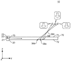
図2は、表示装置10のyz平面の断面を概略的に示す。光源部20は、第1光源21、第2光源22及び第3光源23を備える。第1光源21、第2光源22及び第3光源23は共に、広がり角が小さい光を端面73に入射する。第1光源21、第2光源22及び第3光源23からそれぞれ出射されて導光板70に入射する光の広がり角は、xy面内及びyz面内の両方において所定値より小さい広がり角を持つ。第1光源21、第2光源22及び第3光源23は、例えばLED光源である。具体的には、第1光源21、第2光源22及び第3光源23は、z軸方向の光の広がりを小さくする形状のレンズを持つ。第1光源21、第2光源22及び第3光源23は、当該レンズを通じて導光板70に光を入射することで、導光板70に入射される光のz軸方向の広がりを小さくしてよい。導光板70に入射される光は、当該レンズによってz軸方向の広がりについて実質的にコリメート化され、x軸方向の広がりにはコリメート化されなくてよい。
第1光源21、第2光源22及び第3光源23のそれぞれの光軸が出射面71に平行な面に対してなす角度は、互いに異なる。具体的には、第1光源21の光軸は、出射面71に沿う。第1光源21の光軸は、端面73に実質的に直交する。これにより、第1光源21は、y軸に実質的に平行な光を導光板70に入射する。一方、第2光源22及び第3光源23の光軸は、出射面71に対して傾いており、端面73に実質的に直交しない。また、第2光源22の光軸及び第3光源23の光軸は、実質的に互いに平行でない。このように、第1光源21の光軸、第2光源22及び第3光源23の光軸は、互いに異なる方向を向いている。なお、第1光源21、第2光源22及び第3光源23のそれぞれの光軸が出射面71に平行な面に対してなす角度とは、各光軸が出射面71に平行な面に対してなす角度の鋭角の大きさを意味する。
図2には、第1光源21から光が、光収束部30d、光収束部30d及び光収束部30fのそれぞれによる出射光が示されている。光収束部30d、光収束部30e及び光収束部30fは、導光板70による導光方向(例えば、y軸方向)に沿って、互いに異なる位置に設けられている。ここで、光収束部30dによる出射光は、定点290に収束する。同様に光収束部30eによる出射光及び光収束部30fによる出射光も、定点290に収束する。このように、光収束部30d、光収束部30e及び光収束部30fは、同一の収束点に実質的に収束する、互いに異なる方向の出射光を出射面71から出射させる。
なお、図2では、定点290に出射光が収束する光収束部30のみ示されている。表示装置10は、像6を形成する他の定点についても、各定点に出射光が収束する光収束部30を複数有する。すなわち、導光板70には、像6を形成する複数の定点のうち定点290とは異なる他の同一の定点に収束又は当該同一の定点から発散する互いに異なる方向の出射光を出射面71から出射させる他の複数の光収束部30が、導光板70による導光方向に沿って互いに異なる位置に設けられている。
このように、表示装置10によれば、広がりが小さい光を用いるとともに、同一の収束点に対応する複数の光収束部30が導光方向に沿って異なる位置に設けられている。これにより、y軸方向に異なる位置に向けて略同一の立体像を形成できる。仮に、yz面内における第1光源21からの光の広がりが大きいとすると、光収束部30による出射光はy軸に沿う線上に収束する。そのため、観察者がy軸方向に沿って移動しながら立体像を見ると、像がゆがんで見えたりする場合がある。しかし、表示装置10によれば、y軸方向に異なる位置に向けて別個の光で略同一の立体像を形成できるので、y軸方向に沿って移動する観察者に認識される像のゆがみを抑制できる。
図3は、表示装置10のyz平面の断面を概略的に示す。第1光源21、第2光源22及び第3光源23のそれぞれからの光が光収束部30eに入射した場合の出射光を特に示す。yz面内において、第1光源21からの光が光収束部30eに入射した場合に得られる出射光の出射角と、第2光源22からの光が光収束部30eに入射した場合に得られる出射光の出射角と、第3光源23からの光が光収束部30eに入射した場合に得られる出射光の出射角とは、互いに異なる。特に、これらの出射角は、yz平面内において互いに異なる。このように、入射角が異なる広がりの小さい光を出射する複数の第1光源21、第2光源22及び第3光源23を用いることで、y軸方向に異なる位置に向けて別個の光で略同一の立体像を形成できる。
表示装置10は、光軸が互いに異なる第1光源21、第2光源22及び第3光源23の3個の光源と、同一定点に出射光を収束させる光収束部30d、光収束部30e及び光収束部30fの3個の光収束部30とを有する。これらの光源及び光収束部の組み合わせにより、yz面内で9方向に向けて立体像を形成できる。光軸が異なる光源の数Nと、同一定点に出射光を収束させる光収束部の数Mの組み合わせは任意であってよい。例えば、Nは2であってよいし、4以上であってもよい。Mは2であってよいし、4以上であってもよい。また、Mが2以上である場合、Nは1であってよい。また、Nが2以上である場合、Mは1であってよい。
図4は、光収束部30が有する反射面32の形状を説明する図である。光収束部30dの反射面32dが背面72となす角度をα、光収束部30eの反射面32eが背面72となす角度をβ、光収束部30fの反射面32fが背面72となす角度をγとする。角度α、β及びγは、定点290に実質的に収束する互いに異なる方向の出射光が出射面71から出射されるよう、背面72における光収束部30dの位置と定点290との間の位置関係に基づいて決定される。このように、複数の光収束部30がそれぞれ有する反射面32の角度は、定点に実質的に収束又は定点から実質的に発散する互いに異なる方向の出射光を出射面71から出射させるべく、出射面71に沿う面内の複数の光収束部30のそれぞれの位置と、定点との間の位置関係に基づいて定められる。
なお、認識される像6の輝度は、y軸方向のどの位置から見ても略同一であることが望ましい。そのため、反射面32dの面積、反射面32eの面積及び反射面32fの面積は、光収束部30からそれぞれ出射される光の光度が略同一になるように定められることが望ましい。例えば、光収束部30からそれぞれ出射される光の光度が略同一になるよう、各反射面32の高さh又は反射面32の幅wが、反射面32と背面72とがなす角度に基づいて定められてよい。同一定点に収束する異なる光収束部30の反射面32は、高さh又は反射面32の幅wが互いに異なってよい。
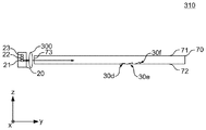
図5は、表示装置10の変形例としての表示装置310を概略的に示す。表示装置310は、表示装置10が備える構成要素に加えて、レンズ300を備える。
レンズ300は、第1光源21と端面73との間の光路内、第2光源22と端面73との間の光路内、及び第3光源23と端面73との間の光路内に設けられる。レンズ300は、第1光源21、第2光源22及び第3光源23のそれぞれの光源からの光のz軸方向の広がりを小さくして、端面73に入射する。このように、レンズ300は、光源部20と導光板70の端面73との間に設けられ、光源部20からの光の広がりを小さくして導光板70の端面73に入射する。これにより、発散角の大きい光源を用いることが可能になる。
図6は、表示装置10の変形例としての表示装置410を概略的に示す。表示装置410は、表示装置10が備える導光板70に代えて、導光板470を備える。導光板470は、端面73に対応する入光端面としての端面473を有する点で、導光板70とは異なる。
端面473は、部分面401、部分面402及び部分面403を有する。部分面401は第1光源21に対応し、部分面402は第2光源22に対応し、部分面403は第3光源23に対応して設けられる。部分面401は、第1光源21の光軸に略直交する。また、部分面402は、第2光源22の光軸に略直交する。部分面403は、第3光源23の光軸に略直交する。このように、導光板470の端面473は、対応する光源からの光が入射する複数の部分面を有し、当該部分面のそれぞれは、対応する光源の光軸に略直交する。これにより、導光板470に入射する光量の低下を抑制できる。
図1から図6に関連して、実質的に同一の定点に向かう方向の光を出射させる複数の光収束部を、導光板70の導光方向に沿って互いに異なる位置に設けた形態を説明した。一方で、図3から明らかなように、出射面71に対する光軸の角度が異なる複数の光源を用いることで、1つの光収束部30eから、yz面内で異なる方向に向かう光を出射させることができる。そこで、上述した表示装置の変形例として、例えば光収束部30d及び光収束部30fを有しない構成を採用してもよい。つまり、上述した表示装置の変形例として、実質的に同一の定点に向かう方向の光を出射させる光収束部を複数設けずに、同一の定点に向かう方向の光を1つの光収束部によって提供する構成を採用してもよい。
図7は、表示装置10を改札機に利用した場合の利用例を概略的に示す。図7は、改札機システム750の全体を示す概略的な斜視図である。図8は、改札機システム750の概略的な分解斜視図である。改札機システム750は、表示装置10を備える光システムの一例である。
改札機システム750は、改札機本体752と、表示システム754と、固定カバー756とを備える。表示システム754は、制御部708と、表示装置10と、表示装置710とを有する。
改札機本体752は、通信部701と表示部702とを有する。通信部701及び表示部702は、ユーザインタフェース部の一例であり、ユーザと改札機本体752との間のインタフェースを提供する。
通信部701は、近接通信を利用して、ユーザが所持する非接触型通信デバイスと通信する。通信部701は、近接通信によって非接触型通信デバイスと通信する。非接触型通信デバイスとしては、ICカード乗車券等のICカード、非接触型通信機能を持つ携帯電話等を例示できる。表示部702は、ユーザに情報を表示する。例えば、表示部702は、非接触型通信デバイスに記憶されている電子マネーの残高等を表示する。
表示装置10及び表示装置710は、表示部702の表示面上に重ねて設けられる。固定カバー756は、表示装置10及び表示装置710の一部を収容して、表示装置10及び表示装置710を改札機本体752に対して固定する。固定カバー756は、表示部702に対応する開口部を有しする。表示部702からの光、並びに、表示装置10及び表示装置710のそれぞれからの出射光は、固定カバー756の開口部を通じて外部に出射光される。
表示装置10による像6は、表示部702の位置をユーザに提示する。像6は、ユーザからは、表示部702の上方の空間に位置するように認識される。
表示装置710は、導光板717と、光源部712とを備える。導光板717は、導光板70に対応し、光源部712は光源部20に対応する。導光板717は、表示装置10が形成する像6とは異なる像を形成する光収束部を有する点を除いて、導光板70の構成と同様の構成を有する。導光板717は、表示部702の表示面を囲う像716を表示する。なお、像716は、像6と同様に、導光板717の出射面とは異なる位置に認識される立体像であってよいし、導光板717の出射面の上方の位置に認識される2次元像であってもよい。
図7に示されるように、表示装置10によれば、表示部702の位置の上方の空間に認識される像6を形成できる。そのため、ユーザが改札機本体752から離れた位置にいても、表示部702が通信部701の近傍に設けられているのか遠方に設けられているのかをユーザが容易に判断することができる。また、表示装置10及び表示装置710は全体として透明であるので、表示部702の表示面上に表示装置10及び表示装置710を載置できる。
なお、表示装置10と同様の構成の表示装置を通信部701上に設けることによって、通信部701の位置をユーザに示す像を、通信部701上の空間に形成してもよい。
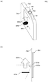
図9は、改札機システム750の変形例としての改札機システム850を概略的に示す。図9(a)は、改札機システム850の全体を示す斜視図である。図9(b)は、改札機システム850のxz面内の平面図である。
改札機システム850は、改札機システム750が備える構成要素に加えて、表示システム854を備える。表示システム854は、表示装置810a及び表示装置810bを有する。表示装置810a及び表示装置810bは、表示装置10の変形例である。表示装置810a及び表示装置810bは、像6とは異なる立体像を形成する光収束部を有する点を除いて、表示装置10と同様の構成を持つ。
改札機本体752の側部は、ユーザが通行する通行面に略垂直であり、ユーザの通行方向に沿う側面758を持つ。表示装置810a及び表示装置810bは、改札機本体752の側面758に設けられる。表示装置810a及び表示装置810bは、y軸が鉛直下方に略一致するように設けられる。表示装置810aの出射面は、側面758と略平行となる。
表示装置810aは、像806aを形成する。表示装置810bは、像806bを形成する。像806aは、表示装置810aの出射面から離れた、通行面の上方の位置に認識される。同様に、像806bは、表示装置810aの出射面から離れた、通行面の上方の位置に認識される。
像806aは、改札機を通ることが許容されている旨を示す。像806aは、例えば通行可能な方向を示す矢印であり、当該矢印が示す方向に改札機を通行することが許容されている旨を示す。像806bは、改札機を通行することが許容されていない旨を示す。像806bは、例えば通行禁止を表すマークである。制御部708は、改札機の通行が許容される旨の信号を取得した場合に、表示装置810aに像806aを形成させ、表示装置810bに像806bを形成させない。一方、制御部708は、改札機の通行を禁止すべき旨の信号を取得した場合に、表示装置810bに像806bを形成させ、表示装置810aに像806aを形成させない。
なお、像806aが進行を許容する向きとは反対の向きから像806aが見えないようにするべく、表示装置810aの光収束部から出射光が出射する角度範囲は、表示装置810aの中心から、進行を許容する向きとは反対側に予め定められた角度θの範囲に限定されている。同様に、像806bが進行を許容する向きとは反対の向きから像806aが見えないようにするべく、表示装置810bの光収束部から出射光が出射する角度範囲も、予め定められた角度θの範囲に限定されている。
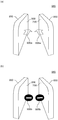
図10は、改札機システム850及び改札機システム950を備えた改札システム960を概略的に示す。改札機システム950は、改札機システム850が備える構成要素と略同一の構成要素を備える。改札機システム950は、改札機システム850の側面758に対応する側面958に、表示システム854と同様の表示システムを有し、当該表示システムによって、像806aと同様の像906a及び像806bと同様の像像906bを形成する。
図10(a)は、改札機を通行することが許容される場合の表示例である。図10(b)は、改札機の通行が禁止されている場合の表示例である。改札機システム850又は改札システム960によれば、通行を禁止するための可動部を削減できる。また、通行を許容する像806aを通行面の上方に認識されるように提示できるので、改札機を通過できる方向をユーザに分かり易く提示することができる。
図11は、券売システム1050の紙幣挿入部を概略的に示す。図11(a)、図11(b)及び図11(c)は、券売システム1050が形成する立体像の切り換えを概略的に示す。券売システム1050は、紙幣挿入部1060と、表示ユニット1011とを備える。紙幣挿入部1060は、ユーザインタフェース部の一例である。表示ユニット1011は、紙幣挿入部1060の下方に設けられる。
表示ユニット1011は、紙幣挿入部1060の紙幣挿入口の近傍に、像1006a、像1006b及び像1006cを独立に形成することができる。像1006a、像1006b及び像1006cは、表示ユニット1011の表示面より上方に位置する立体像である。表示ユニット1011は、像1006a、像1006b及び像1006cを、時間的に順次に切り換えて形成する。例えば、表示ユニット1011は、像1006aを予め定められた時間形成した後、像1006bを予め定められた時間形成し、次いで像1006aを予め定められた時間形成する。その後、同様に、像1006aの形成、像1006bの形成、像1006cの形成を順次に繰り返す。一表示形態では、像1006a、像1006b及び像1006cは同時には形成されない。他の表示形態では、像1006a、像1006b及び像1006cは同時に形成されてよい。
図12は、券売システム1050のカード読取部を概略的に示す。図12(a)、図12(b)及び図12(c)は、券売システム1050が形成する立体像の切り換えの他の例を概略的に示す。券売システム1050は、カード読取部1062と、表示ユニット1012とを備える。カード読取部1062は、ユーザインタフェース部の一例である。表示ユニット1012は、カード読取部1062上に設けられる。
表示ユニット1012は、カード読取部1062の上方に、像1006d、像1006e及び像1006fを独立に形成することができる。像1006d、像1006e及び像1006fは、表示ユニット1012の表示面より上方に位置する立体像である。表示ユニット1012は、像1006d、像1006e及び像1006fを、時間的に順次に切り換えて形成する。例えば、表示ユニット1012は、像1006dを予め定められた時間形成した後、像1006eを予め定められた時間形成し、次いで像1006fを予め定められた時間形成する。その後、同様に、像1006dの形成、像1006eの形成、像1006fの形成を順次に繰り返す。一表示形態では、像1006d、像1006e及び像1006fは同時には形成されない。他の表示形態では、像1006d、像1006e及び像1006fは同時に形成されてよい。
図13は、表示ユニット1011の構成を概略的に示す。表示ユニット1011は、表示装置1010a、表示装置1010b及び表示装置1010cを有する。表示装置1010aは、光源部1020a及び導光板1070aを有する。表示装置1010bは、光源部1020b及び導光板1070bを有する。表示装置1010cは、光源部1020c及び導光板1070cを有する。
光源部1020a、光源部1020b及び光源部1020cは、光源部20と略同一の構成を有する。導光板1070a、導光板1070b及び導光板1070cは、フレキシブルな材料で形成される。また、導光板1070a、導光板1070b及び導光板1070cは、像6とは異なる像を形成する光収束部を有する。これらの点を除いて、導光板1070a、導光板1070b及び導光板1070cは、導光板70と略同様の構成を有する。表示ユニット1011において、z軸プラス方向に沿って、表示装置1010a、表示装置1010b及び表示装置1010cの順で重ねて設けられる。
導光板1070aは、像1006aを形成するための光収束部を有する。導光板1070bは、像1006bを形成するための光収束部を有する。導光板1070cは、像1006cを形成するための光収束部を有する。したがって、光源部20a、光源部20b及び光源部20cのうち、実際に発光させる光源部を、光源部20a、光源部20b及び光源部20cの順で切り換えることによって、像1006a、像1006b及び像1006cを時間的に順次に切り換えて形成することができる。
図14は、表示ユニット1011の変形例としての表示ユニット1111を概略的に示す。図14(a)は、z軸プラス方向の位置から表示ユニット1111を見た場合のxy面内の平面図である。図14(b)は、y軸マイナス方向の位置から表示ユニット1111を見た場合のxz面内の平面図である。表示ユニット1111は、表示ユニット1011の光源部1020aに代えて光源部1120aを有し、光源部1020bに代えて光源部1120bを有し、光源部1020cに代えて光源部1120cを有する。表示ユニット1111は、表示ユニット1011が備える他の構成要素に加えて、遮光部1140a、遮光部1140b及び遮光部1140cと、スペーサ1151及びスペーサ1152とを更に備える。図14(b)は、表示ユニット1111をz軸プラス方向の位置から見た場合のxy面に沿う平面図である。
光源部1120aは、導光板1070aの入光端面、導光板1070bの入光端面及び導光板1070cの入光端面に渡って設けられる。同様に、光源部1120bは、導光板1070aの入光端面、導光板1070bの入光端面及び導光板1070cの入光端面に渡って設けられる。また、光源部1120cは、導光板1070aの入光端面、導光板1070bの入光端面及び導光板1070cの入光端面に渡って設けられる。
遮光部1140a、遮光部1140b及び遮光部1140cは、光を遮る。遮光部1140a、遮光部1140b及び遮光部1140cは、例えば遮光テープや遮光膜である。遮光部1140aは、導光板1070aの入光端面の一部に設けられる。遮光部1140aは、光源部1120bからの光及び光源部1120cからの光が表示装置1010aに入射することを抑制する。また、遮光部1140bは、導光板1070bの入光端面の一部に設けられ、光源部1120aからの光及び光源部1120cからの光が表示装置1010bに入射することを抑制する。遮光部1140cは、導光板1070cの入光端面の一部に設けられ、光源部1120aからの光及び光源部1120bからの光が表示装置1010cに入射することを抑制する。
具体的には、図14(a)及び図14(b)に示されるように、遮光部1140bは、導光板1070bの入光端面と光源部1120aとの間、及び、導光板1070bの入光端面と光源部1120cとの間に、少なくとも設けられる。遮光部1140bは、導光板1070bの入光端面のうち、光源部1120bが設けられた位置には設けられていない。これにより、光源部1120bからの光が導光板1070bの入光端面から入射する一方、光源部1120aからの光及び光源部1120cからの光が導光板1070bの入光端面に実質的に入射しないようにすることができる。
同様に、遮光部1140aは、導光板1070aの入光端面と光源部1120bとの間、及び、導光板1070aの入光端面と光源部1120cとの間に、少なくとも設けられる。遮光部1140aは、導光板1070aの入光端面のうち、光源部1120aが設けられた位置には設けられていない。これにより、光源部1120aからの光が導光板1070aの入光端面に入射する一方、光源部1120bからの光及び光源部1120cからの光が導光板1070aの入光端面に実質的に入射しないようにすることができる。
また、遮光部1140cは、導光板1070cの入光端面と光源部1120aとの間、及び、導光板1070cの入光端面と光源部1120bとの間に、少なくとも設けられる。遮光部1140cは、導光板1070cの入光端面のうち、光源部1120cが設けられた位置には設けられていない。これにより、光源部1120cからの光が導光板1070cの入光端面に入射する一方、光源部1120aからの光及び光源部1120bからの光が導光板1070cの入光端面に実質的に入射しないようにすることができる。
また、スペーサ1151は、表示装置1010aと表示装置1010bとの間に設けられる。スペーサ1152は、表示装置1010bと表示装置1010cとの間に設けられる。スペーサ1151により、表示装置1010aと表示装置1010bとが密着することを防ぐことができる。また、スペーサ1152により、表示装置1010bと表示装置1010cとが密着することを防ぐことができる。
なお、図13及び14に関連して説明した表示ユニット1011又は表示ユニット1111と同様の構成を、表示ユニット1012に適用できる。
図15は、光収束部30の変形例としての光収束部130及び光収束部132を概略的に示す。図14(a)は、フレネルレンズの一部により形成された1つの光収束部130を概略的に示す。なお、フレネルレンズとして機能する光収束部130の複数の屈折面(プリズム面)の間には、隙間が設けられてよい。
図14(b)に示す光収束部132は、光収束部130を、x軸方向に沿って複数の部分140a、部分140b、部分140c、部分140d、部分140e、部分140f、部分140g及び部分140hに分割したものに対応する。光収束部132の各部分140のそれぞれからの光は、同一の定点に収束する。このように、光収束部を複数の部分に分割することで、いわゆるブラックマトリックス効果が生じて、像のコントラストが高まる場合がある。なお、反射面やフレネルレンズの他に、光収束部30として回折格子を用いてもよい。
以上、本発明を実施の形態を用いて説明したが、本発明の技術的範囲は上記実施の形態に記載の範囲には限定されない。上記実施の形態に、多様な変更又は改良を加えることが可能であることが当業者に明らかである。その様な変更又は改良を加えた形態も本発明の技術的範囲に含まれ得ることが、請求の範囲の記載から明らかである。
請求の範囲、明細書、及び図面中において示した装置、システム、プログラム、及び方法における動作、手順、ステップ、及び段階等の各処理の実行順序は、特段「より前に」、「先立って」等と明示しておらず、また、前の処理の出力を後の処理で用いるのでない限り、任意の順序で実現しうることに留意すべきである。請求の範囲、明細書、及び図面中の動作フローに関して、便宜上「まず、」、「次に、」等を用いて説明したとしても、この順で実施することが必須であることを意味するものではない。
6 像
10 表示装置
20 光源部
21 第1光源、22 第2光源、23 第3光源
30 光収束部
32 反射面
70 導光板
71 出射面
72 背面
73、74、75、76 端面
130、132 光収束部
140 部分
190 線
290 定点
300 レンズ
310 表示装置
401、402、403 部分面
410 表示装置
470 導光板
473 端面
701 通信部
702 表示部
708 制御部
710 表示装置
712 光源部
716 像
717 導光板
750 改札機システム
752 改札機本体
754 表示システム
756 固定カバー
758 側面
806 像
810 表示装置
850 改札機システム
854 表示システム
950 改札機システム
960 改札システム
1006 像
1010 表示装置
1011 表示ユニット
1020 光源部
1050 券売システム
1060 紙幣挿入部
1070 導光板
1111 表示ユニット
1120 光源部
1140 遮光部
1151、1152 スペーサ
10 表示装置
20 光源部
21 第1光源、22 第2光源、23 第3光源
30 光収束部
32 反射面
70 導光板
71 出射面
72 背面
73、74、75、76 端面
130、132 光収束部
140 部分
190 線
290 定点
300 レンズ
310 表示装置
401、402、403 部分面
410 表示装置
470 導光板
473 端面
701 通信部
702 表示部
708 制御部
710 表示装置
712 光源部
716 像
717 導光板
750 改札機システム
752 改札機本体
754 表示システム
756 固定カバー
758 側面
806 像
810 表示装置
850 改札機システム
854 表示システム
950 改札機システム
960 改札システム
1006 像
1010 表示装置
1011 表示ユニット
1020 光源部
1050 券売システム
1060 紙幣挿入部
1070 導光板
1111 表示ユニット
1120 光源部
1140 遮光部
1151、1152 スペーサ
Claims (11)
- 1以上の光源と、
前記光源からの光を、光の出射面に平行な面内で導く導光板と
を備え、
前記導光板は、
前記導光板によって導かれている光が入射し、空間上の1つの収束点に実質的に収束する又は空間上の1つの収束点から実質的に発散する方向の出射光を前記出射面から出射させる光学面をそれぞれ有する複数の光収束部
を有し、
前記収束点は前記複数の光収束部の間で互いに異なり、複数の前記収束点の集まりによって、前記出射面側の空間上に像が形成され、
前記複数の光収束部のうち前記導光板が光を導く導光方向に沿って互いに異なる位置に設けられた複数の第1の光収束部が、前記複数の収束点のうち同一の第1の収束点に実質的に収束又は前記第1の収束点から実質的に発散する互いに異なる方向の出射光を、前記出射面から出射させる
光デバイス。 - 前記複数の光収束部のうち前記導光方向に沿って互いに異なる位置に設けられた複数の第2の光収束部が、前記複数の収束点のうち前記第1の収束点とは異なる同一の第2の収束点に実質的に収束又は前記第2の収束点から実質的に発散する互いに異なる方向の出射光を前記出射面から出射させる
請求項1に記載の光デバイス。 - 前記複数の第1の光収束部がそれぞれ有する前記光学面の面積は、前記複数の第1の光収束部からそれぞれ出射される光の光度が略同一になるように定められる
請求項1又は2に記載の光デバイス。 - 前記複数の第1の光収束部がそれぞれ有する前記光学面は、入射した光を反射する反射面であり、
前記複数の第1の光収束部がそれぞれ有する前記反射面の角度は、前記第1の収束点に実質的に収束又は前記第1の収束点から実質的に発散する互いに異なる方向の出射光を前記出射面から出射させるべく、前記出射面に沿う面内の前記複数の第1の光収束部のそれぞれの位置と、前記第1の収束点との間の位置関係に基づいて定められる
請求項1から3のいずれか1項に記載の光デバイス。 - 前記光源は複数設けられ、
複数の前記光源のそれぞれの光軸が前記出射面に平行な面に対してなす角度は互いに異なる
請求項1又は2に記載の光デバイス。 - 複数の光源と、
前記複数の光源からの光を、光の出射面に平行な面内で導く導光板と、
を備え、
前記複数の光源のそれぞれの光軸が前記出射面に平行な面に対してなす角度は互いに異なり、
前記導光板は、
前記導光板によって導かれている光が入射し、空間上の1つの収束点に実質的に収束する又は空間上の1つの収束点から実質的に発散する方向の出射光を前記出射面から出射させる光学面をそれぞれ有する複数の光収束部
を有し、
前記収束点は前記複数の光収束部の間で互いに異なり、複数の前記収束点の集まりによって、前記出射面側の空間上に像が形成される
光デバイス。 - 前記導光板の入光端面は、前記複数の光源のうち対応する光源からの光が入射する複数の部分面を有し、
前記複数の部分面のそれぞれは、前記複数の光源のうち前記対応する光源の光軸に略直交する
請求項5又は6に記載の光デバイス。 - 前記光源と前記導光板の入光端面との間に設けられ、前記光源からの光の広がりを小さくして前記導光板の入光端面に入射するレンズ部
を更に備える請求項1から7のいずれか1項に記載の光デバイス。 - 前記複数の光収束部は、前記出射面に平行な面内でそれぞれ予め定められた線に沿って形成されている
請求項1から8のいずれか1項に記載の光デバイス。 - 請求項1から9のいずれか1項に記載の光デバイスと、
ユーザインタフェース部と
を備え、
前記光デバイスは、前記ユーザインタフェース部の位置をユーザに示す前記像を形成する
光システム。 - 請求項10に記載の光システム
を備える改札機。
Priority Applications (3)
| Application Number | Priority Date | Filing Date | Title |
|---|---|---|---|
| DE112015005939.3T DE112015005939B4 (de) | 2015-01-13 | 2015-12-28 | Optische Vorrichtung, optisches System und Zugangsschranke |
| CN201580070034.0A CN107111976B (zh) | 2015-01-13 | 2015-12-28 | 光学设备、光学系统及检票机 |
| US15/538,702 US10371349B2 (en) | 2015-01-13 | 2015-12-28 | Optical device, optical system, and ticket gate |
Applications Claiming Priority (4)
| Application Number | Priority Date | Filing Date | Title |
|---|---|---|---|
| JP2015004536 | 2015-01-13 | ||
| JP2015-004536 | 2015-01-13 | ||
| JP2015180921A JP6520594B2 (ja) | 2015-01-13 | 2015-09-14 | 光デバイス、光システム及び改札機 |
| JP2015-180921 | 2015-09-14 |
Publications (1)
| Publication Number | Publication Date |
|---|---|
| WO2016114101A1 true WO2016114101A1 (ja) | 2016-07-21 |
Family
ID=56405655
Family Applications (1)
| Application Number | Title | Priority Date | Filing Date |
|---|---|---|---|
| PCT/JP2015/086571 Ceased WO2016114101A1 (ja) | 2015-01-13 | 2015-12-28 | 光デバイス、光システム及び改札機 |
Country Status (1)
| Country | Link |
|---|---|
| WO (1) | WO2016114101A1 (ja) |
Cited By (2)
| Publication number | Priority date | Publication date | Assignee | Title |
|---|---|---|---|---|
| JP2020072028A (ja) * | 2018-10-31 | 2020-05-07 | オムロン株式会社 | 表示装置 |
| WO2020179870A1 (ja) * | 2019-03-06 | 2020-09-10 | オムロン株式会社 | 表示装置、非接触スイッチ、および電子機器 |
Citations (3)
| Publication number | Priority date | Publication date | Assignee | Title |
|---|---|---|---|---|
| JP2009540440A (ja) * | 2006-06-06 | 2009-11-19 | スリーエム イノベイティブ プロパティズ カンパニー | 仮想イメージを有するキーパッド |
| JP2012118378A (ja) * | 2010-12-02 | 2012-06-21 | Stanley Electric Co Ltd | 画像表示装置 |
| US20140268327A1 (en) * | 2013-03-15 | 2014-09-18 | Opsec Security Group, Inc. | Optically variable device exhibiting non-diffractive three-dimensional optical effect |
-
2015
- 2015-12-28 WO PCT/JP2015/086571 patent/WO2016114101A1/ja not_active Ceased
Patent Citations (3)
| Publication number | Priority date | Publication date | Assignee | Title |
|---|---|---|---|---|
| JP2009540440A (ja) * | 2006-06-06 | 2009-11-19 | スリーエム イノベイティブ プロパティズ カンパニー | 仮想イメージを有するキーパッド |
| JP2012118378A (ja) * | 2010-12-02 | 2012-06-21 | Stanley Electric Co Ltd | 画像表示装置 |
| US20140268327A1 (en) * | 2013-03-15 | 2014-09-18 | Opsec Security Group, Inc. | Optically variable device exhibiting non-diffractive three-dimensional optical effect |
Non-Patent Citations (6)
| Title |
|---|
| CEATEC: "Omron Rittai Toei Gazo", YOUTUBE, 6 October 2014 (2014-10-06), Retrieved from the Internet <URL:https://www.youtube.com/watch?v=izkYqWOosmA> [retrieved on 20160311] * |
| ITMEDIA NEWS: "Tomeiita to LED 1-ko de Jitsugen suru Ukabu 3D Eizo sono Shikumi wa", CEATEC, 7 October 2014 (2014-10-07), JAPAN, Retrieved from the Internet <URL:http://www.itmedia.co.jp/news/articles/1410/07/news117.html> [retrieved on 20160311] * |
| MAINICHI SHINBUN: "Omron Usui Sheet 1-mai to LED de 3D Gazo Toei", CEATEC, 7 October 2014 (2014-10-07), Retrieved from the Internet <URL:http://mainichi.jp/articles/20141007/mog/00m/010/012000c> [retrieved on 20160311] * |
| MYNAVI NEWS ET AL.: "Mageru Koto mo Kano na Tomei Plate kara 3D Gazo o Toei suru Gijutsu o Kaihatsu", 3 October 2014 (2014-10-03), Retrieved from the Internet <URL:http://news.mynavi.jp/news/2014/10/03/181> [retrieved on 20160311] * |
| OMRON CORP.: "News Release-2014 Nen, Sekaihatsu Tomei Plate o Mochiita Kukan Toei Gijutsu o Kaihatsu", 2 October 2014 (2014-10-02), Retrieved from the Internet <URL:http://www.omron.co.jp/press/2014/10/e1002.html> [retrieved on 20160311] * |
| RBB TODAY: "Pop ya Annai Hyoji ga Kawaru! Omron no Kukan Toei Gijutsu", CEATEC, vol. 13, 7 October 2014 (2014-10-07), Retrieved from the Internet <URL:http://www.rbbtoday.com/article/2014/10/07/124175.html> [retrieved on 20160311] * |
Cited By (6)
| Publication number | Priority date | Publication date | Assignee | Title |
|---|---|---|---|---|
| JP2020072028A (ja) * | 2018-10-31 | 2020-05-07 | オムロン株式会社 | 表示装置 |
| JP7110917B2 (ja) | 2018-10-31 | 2022-08-02 | オムロン株式会社 | 表示装置 |
| WO2020179870A1 (ja) * | 2019-03-06 | 2020-09-10 | オムロン株式会社 | 表示装置、非接触スイッチ、および電子機器 |
| JPWO2020179870A1 (ja) * | 2019-03-06 | 2020-09-10 | ||
| CN113412444A (zh) * | 2019-03-06 | 2021-09-17 | 欧姆龙株式会社 | 显示装置、非接触开关以及电子设备 |
| JP7120436B2 (ja) | 2019-03-06 | 2022-08-17 | オムロン株式会社 | 表示装置、非接触スイッチ、および電子機器 |
Similar Documents
| Publication | Publication Date | Title |
|---|---|---|
| JP6558166B2 (ja) | 光デバイス及び操作入力装置 | |
| US20200158944A1 (en) | Display device and display method | |
| CN117075345A (zh) | 用于照射空间光调制器的方法、设备和系统 | |
| CN109642716A (zh) | 包括厚介质的虚拟现实、增强现实和混合现实系统及相关方法 | |
| JP6638274B2 (ja) | 光デバイス及び光システム | |
| JP6520594B2 (ja) | 光デバイス、光システム及び改札機 | |
| CN115509006B (zh) | 光学设备及电子设备 | |
| JP6418065B2 (ja) | 光デバイス | |
| JP6531583B2 (ja) | 光デバイス、光システム及び改札機 | |
| US10598845B2 (en) | Optical device and optical system | |
| WO2016114101A1 (ja) | 光デバイス、光システム及び改札機 | |
| JP6631839B2 (ja) | 照明装置および画像表示装置 | |
| KR20220123136A (ko) | 애니메이션형 정적 멀티뷰 디스플레이 및 방법 | |
| WO2016114103A1 (ja) | 光デバイス、光システム及び改札機 | |
| US12111470B2 (en) | Optical system and mixed reality device | |
| WO2016114104A1 (ja) | 光デバイス及び光システム | |
| CN105242773A (zh) | 一种电子设备 | |
| US11966064B2 (en) | Light guide plate device including an optical path changer | |
| CN214335368U (zh) | 一种光学系统及混合现实设备 | |
| WO2016114102A1 (ja) | 光デバイス及び操作入力装置 |
Legal Events
| Date | Code | Title | Description |
|---|---|---|---|
| 121 | Ep: the epo has been informed by wipo that ep was designated in this application |
Ref document number: 15878052 Country of ref document: EP Kind code of ref document: A1 |
|
| WWE | Wipo information: entry into national phase |
Ref document number: 15538702 Country of ref document: US |
|
| WWE | Wipo information: entry into national phase |
Ref document number: 112015005939 Country of ref document: DE |
|
| 122 | Ep: pct application non-entry in european phase |
Ref document number: 15878052 Country of ref document: EP Kind code of ref document: A1 |