WO2016113910A1 - 監視計画の評価システムおよび監視計画の評価方法 - Google Patents
監視計画の評価システムおよび監視計画の評価方法 Download PDFInfo
- Publication number
- WO2016113910A1 WO2016113910A1 PCT/JP2015/051090 JP2015051090W WO2016113910A1 WO 2016113910 A1 WO2016113910 A1 WO 2016113910A1 JP 2015051090 W JP2015051090 W JP 2015051090W WO 2016113910 A1 WO2016113910 A1 WO 2016113910A1
- Authority
- WO
- WIPO (PCT)
- Prior art keywords
- monitoring
- vehicle
- information
- traffic
- execution condition
- Prior art date
- Legal status (The legal status is an assumption and is not a legal conclusion. Google has not performed a legal analysis and makes no representation as to the accuracy of the status listed.)
- Ceased
Links
Images




Classifications
-
- G—PHYSICS
- G07—CHECKING-DEVICES
- G07B—TICKET-ISSUING APPARATUS; FARE-REGISTERING APPARATUS; FRANKING APPARATUS
- G07B15/00—Arrangements or apparatus for collecting fares, tolls or entrance fees at one or more control points
- G07B15/06—Arrangements for road pricing or congestion charging of vehicles or vehicle users, e.g. automatic toll systems
- G07B15/063—Arrangements for road pricing or congestion charging of vehicles or vehicle users, e.g. automatic toll systems using wireless information transmission between the vehicle and a fixed station
-
- G—PHYSICS
- G07—CHECKING-DEVICES
- G07B—TICKET-ISSUING APPARATUS; FARE-REGISTERING APPARATUS; FRANKING APPARATUS
- G07B15/00—Arrangements or apparatus for collecting fares, tolls or entrance fees at one or more control points
- G07B15/06—Arrangements for road pricing or congestion charging of vehicles or vehicle users, e.g. automatic toll systems
-
- G—PHYSICS
- G06—COMPUTING OR CALCULATING; COUNTING
- G06Q—INFORMATION AND COMMUNICATION TECHNOLOGY [ICT] SPECIALLY ADAPTED FOR ADMINISTRATIVE, COMMERCIAL, FINANCIAL, MANAGERIAL OR SUPERVISORY PURPOSES; SYSTEMS OR METHODS SPECIALLY ADAPTED FOR ADMINISTRATIVE, COMMERCIAL, FINANCIAL, MANAGERIAL OR SUPERVISORY PURPOSES, NOT OTHERWISE PROVIDED FOR
- G06Q50/00—Information and communication technology [ICT] specially adapted for implementation of business processes of specific business sectors, e.g. utilities or tourism
- G06Q50/40—Business processes related to the transportation industry
-
- G—PHYSICS
- G06—COMPUTING OR CALCULATING; COUNTING
- G06Q—INFORMATION AND COMMUNICATION TECHNOLOGY [ICT] SPECIALLY ADAPTED FOR ADMINISTRATIVE, COMMERCIAL, FINANCIAL, MANAGERIAL OR SUPERVISORY PURPOSES; SYSTEMS OR METHODS SPECIALLY ADAPTED FOR ADMINISTRATIVE, COMMERCIAL, FINANCIAL, MANAGERIAL OR SUPERVISORY PURPOSES, NOT OTHERWISE PROVIDED FOR
- G06Q10/00—Administration; Management
- G06Q10/06—Resources, workflows, human or project management; Enterprise or organisation planning; Enterprise or organisation modelling
- G06Q10/063—Operations research, analysis or management
-
- G—PHYSICS
- G06—COMPUTING OR CALCULATING; COUNTING
- G06Q—INFORMATION AND COMMUNICATION TECHNOLOGY [ICT] SPECIALLY ADAPTED FOR ADMINISTRATIVE, COMMERCIAL, FINANCIAL, MANAGERIAL OR SUPERVISORY PURPOSES; SYSTEMS OR METHODS SPECIALLY ADAPTED FOR ADMINISTRATIVE, COMMERCIAL, FINANCIAL, MANAGERIAL OR SUPERVISORY PURPOSES, NOT OTHERWISE PROVIDED FOR
- G06Q10/00—Administration; Management
- G06Q10/06—Resources, workflows, human or project management; Enterprise or organisation planning; Enterprise or organisation modelling
- G06Q10/063—Operations research, analysis or management
- G06Q10/0631—Resource planning, allocation, distributing or scheduling for enterprises or organisations
-
- G—PHYSICS
- G06—COMPUTING OR CALCULATING; COUNTING
- G06Q—INFORMATION AND COMMUNICATION TECHNOLOGY [ICT] SPECIALLY ADAPTED FOR ADMINISTRATIVE, COMMERCIAL, FINANCIAL, MANAGERIAL OR SUPERVISORY PURPOSES; SYSTEMS OR METHODS SPECIALLY ADAPTED FOR ADMINISTRATIVE, COMMERCIAL, FINANCIAL, MANAGERIAL OR SUPERVISORY PURPOSES, NOT OTHERWISE PROVIDED FOR
- G06Q50/00—Information and communication technology [ICT] specially adapted for implementation of business processes of specific business sectors, e.g. utilities or tourism
- G06Q50/10—Services
-
- G—PHYSICS
- G06—COMPUTING OR CALCULATING; COUNTING
- G06Q—INFORMATION AND COMMUNICATION TECHNOLOGY [ICT] SPECIALLY ADAPTED FOR ADMINISTRATIVE, COMMERCIAL, FINANCIAL, MANAGERIAL OR SUPERVISORY PURPOSES; SYSTEMS OR METHODS SPECIALLY ADAPTED FOR ADMINISTRATIVE, COMMERCIAL, FINANCIAL, MANAGERIAL OR SUPERVISORY PURPOSES, NOT OTHERWISE PROVIDED FOR
- G06Q50/00—Information and communication technology [ICT] specially adapted for implementation of business processes of specific business sectors, e.g. utilities or tourism
- G06Q50/10—Services
- G06Q50/26—Government or public services
- G06Q50/265—Personal security, identity or safety
-
- G—PHYSICS
- G07—CHECKING-DEVICES
- G07B—TICKET-ISSUING APPARATUS; FARE-REGISTERING APPARATUS; FRANKING APPARATUS
- G07B15/00—Arrangements or apparatus for collecting fares, tolls or entrance fees at one or more control points
-
- G—PHYSICS
- G08—SIGNALLING
- G08G—TRAFFIC CONTROL SYSTEMS
- G08G1/00—Traffic control systems for road vehicles
-
- G—PHYSICS
- G08—SIGNALLING
- G08G—TRAFFIC CONTROL SYSTEMS
- G08G1/00—Traffic control systems for road vehicles
- G08G1/01—Detecting movement of traffic to be counted or controlled
-
- G—PHYSICS
- G08—SIGNALLING
- G08G—TRAFFIC CONTROL SYSTEMS
- G08G1/00—Traffic control systems for road vehicles
- G08G1/01—Detecting movement of traffic to be counted or controlled
- G08G1/0104—Measuring and analyzing of parameters relative to traffic conditions
- G08G1/0108—Measuring and analyzing of parameters relative to traffic conditions based on the source of data
- G08G1/0116—Measuring and analyzing of parameters relative to traffic conditions based on the source of data from roadside infrastructure, e.g. beacons
-
- G—PHYSICS
- G08—SIGNALLING
- G08G—TRAFFIC CONTROL SYSTEMS
- G08G1/00—Traffic control systems for road vehicles
- G08G1/01—Detecting movement of traffic to be counted or controlled
- G08G1/0104—Measuring and analyzing of parameters relative to traffic conditions
- G08G1/0125—Traffic data processing
- G08G1/0129—Traffic data processing for creating historical data or processing based on historical data
-
- G—PHYSICS
- G08—SIGNALLING
- G08G—TRAFFIC CONTROL SYSTEMS
- G08G1/00—Traffic control systems for road vehicles
- G08G1/01—Detecting movement of traffic to be counted or controlled
- G08G1/017—Detecting movement of traffic to be counted or controlled identifying vehicles
- G08G1/0175—Detecting movement of traffic to be counted or controlled identifying vehicles by photographing vehicles, e.g. when violating traffic rules
-
- G—PHYSICS
- G08—SIGNALLING
- G08G—TRAFFIC CONTROL SYSTEMS
- G08G1/00—Traffic control systems for road vehicles
- G08G1/065—Traffic control systems for road vehicles by counting the vehicles in a section of the road or in a parking area, i.e. comparing incoming count with outgoing count
-
- G—PHYSICS
- G08—SIGNALLING
- G08G—TRAFFIC CONTROL SYSTEMS
- G08G1/00—Traffic control systems for road vehicles
- G08G1/123—Traffic control systems for road vehicles indicating the position of vehicles, e.g. scheduled vehicles; Managing passenger vehicles circulating according to a fixed timetable, e.g. buses, trains, trams
- G08G1/127—Traffic control systems for road vehicles indicating the position of vehicles, e.g. scheduled vehicles; Managing passenger vehicles circulating according to a fixed timetable, e.g. buses, trains, trams to a central station ; Indicators in a central station
Definitions
- the present invention relates to a monitoring plan evaluation system and a monitoring plan evaluation method.
- Patent Document 1 describes a toll collection vehicle-mounted device that performs location determination of a passing vehicle by GPS (Global Positioning System) and performs charging processing based on charging conditions and vehicle position information. Has been.
- GPS Global Positioning System
- the vehicle-mounted device can autonomously perform the charging process even in a place where there is no roadside equipment. Therefore, in this method, roadside facilities can be reduced, and charging conditions can be set and changed flexibly.
- the traffic situation of vehicles on which fraud to be controlled such as on-vehicle devices is fraudulent is considered to vary depending on the location and time, and vehicles that are fraudulent depending on the location and time of monitoring for enforcement It is thought that the detection situation of is different. Therefore, it is desirable to be able to predict at least one of a location and a time at which a fraudulent vehicle can be efficiently detected.
- the present invention provides a monitoring plan evaluation system and a monitoring plan evaluation method capable of providing information for predicting at least one of a place and a time at which a vehicle in which fraud has been performed can be efficiently detected.
- the monitoring plan evaluation system (100) includes monitoring execution condition information indicating at least one of a vehicle monitoring location and a monitoring time, and a monitoring target at the monitoring location or the monitoring time.
- a vehicle monitoring information acquisition unit (110) that acquires vehicle monitoring information indicating the monitoring result of the vehicle, and movement information acquisition that acquires vehicle movement information regarding movement of each vehicle for a plurality of vehicles
- a traffic degree information indicating a degree of traffic of a vehicle to be monitored in a condition indicated by a part (110) and at least one of a location and time at which the vehicle is monitored and a monitoring performance condition candidate.
- a traffic degree information generating unit (191) that generates based on the vehicle monitoring information.
- the vehicle to be monitored is a vehicle whose necessity for monitoring is increasing because of the high probability that fraud related to the vehicle has been performed.
- the degree of traffic of vehicles that should be monitored under the conditions indicated by each monitoring execution condition candidate in consideration of the monitoring results of each vehicle obtained from the vehicle monitoring information Can be generated.
- the monitoring plan evaluation system may include a candidate selection unit (192) that selects one or more monitoring execution condition candidates from a plurality of monitoring execution condition candidates based on the traffic degree information.
- the traffic level information generation unit may generate map information including information indicating the level of traffic of a vehicle to be monitored as the traffic level information. As a result, the location and time for monitoring are determined while confirming the point where it is expected to be able to efficiently detect the vehicle not equipped with the vehicle-mounted device with the map information constituting the degree of traffic information. Can do.
- the traffic degree information generating unit extracts at least one of a monitoring location and a monitoring time at which the vehicle was last monitored based on the vehicle monitoring information, and based on a travel history indicated by the vehicle movement information, The monitoring execution condition candidate that has passed after the monitoring location or the monitoring time monitored is extracted, and the time interval from when the vehicle was last monitored until the vehicle passes through the extracted monitoring execution condition candidate
- the traffic degree information may be generated based on at least one of the travel distance and the billing amount.
- the degree-of-traffic information generation unit varies according to at least one of the time interval, travel distance, and billing amount from when the vehicle was last monitored until the vehicle passes in the extracted monitoring execution condition candidates. Can be generated. For this reason, for example, the longer the time since monitoring has been performed, the longer the distance traveled, or the greater the number of vehicles that have been charged for a large amount of traffic, the corresponding monitoring execution condition candidate indicates The condition can be evaluated as a condition that the vehicle to be monitored is passing (that is, a condition that is more suitable for monitoring an unauthorized vehicle).
- the traffic degree information generation unit obtains at least a charge amount from when the vehicle was last monitored until the vehicle passes in the extracted monitoring execution condition candidates, and the vehicle passing through the monitoring execution condition candidates
- the degree of traffic information may be generated such that the greater the charge amount, the higher the level of traffic of the vehicle to be monitored.
- the traffic level information generation unit can present a place or time suitable for monitoring for preventing or detecting a large amount of charge escape. For this reason, for example, the operator of the automatic billing system can efficiently perform monitoring for preventing or detecting expensive billing evasion by performing monitoring at the place or time.
- a monitoring plan evaluation method includes monitoring execution condition information indicating at least one of a monitoring location and a monitoring time of a vehicle, and a vehicle to be monitored at the monitoring location or monitoring time.
- a vehicle monitoring information acquisition step for acquiring vehicle monitoring information indicating a vehicle monitoring result
- a movement information acquisition step for acquiring vehicle movement information regarding movement of each vehicle, and monitoring the vehicle.
- the traffic degree information indicating the degree of traffic of the vehicle to be monitored under the condition indicated by the monitoring execution condition candidate including at least one of the place to perform and the time is generated.
- a traffic degree information generation step is generated.
- the degree of traffic of vehicles that should be monitored under the conditions indicated by each monitoring execution condition candidate in consideration of the monitoring results of each vehicle obtained from the vehicle monitoring information Can be generated.
- traffic degree information it is possible to obtain information for predicting at least one of a monitoring place and a monitoring time at which monitoring should be performed, that is, a highly probable vehicle in which fraud related to the vehicle has been performed can be efficiently detected. it can.
- the monitoring plan evaluation system and the monitoring plan evaluation method described above it is possible to provide information for predicting at least one of a location and a time at which a vehicle in which fraud has been performed can be efficiently detected.
- FIG. 1 is a schematic block diagram showing a functional configuration of an automatic charging system according to an embodiment of the present invention.
- the automatic billing system 1 includes a monitoring plan evaluation server device 100, a billing server device 200, and a monitoring subsystem 400.
- the monitoring plan evaluation server device 100 includes a communication unit 110, a display unit 120, a storage unit 180, and a control unit 190.
- the control unit 190 includes a traffic degree information generation unit 191 and a candidate selection unit 192.
- the monitoring subsystem 400 includes a billing server communication device 410, a camera 420, a DSRC (Dedicated Short Range Communication) communication device 430, and a control device 490.
- DSRC Dedicated Short Range Communication
- the monitoring sub-system 400 included in the automatic billing system 1 is installed at a position where a passing vehicle can be monitored in an area where the vehicle to be monitored passes.
- the number of such monitoring subsystems 400 is arbitrary.
- some or all of the monitoring subsystems 400 may not be installed yet, such as planned to be installed.
- the billing server device 200 includes a communication unit that communicates with the vehicle-mounted device 310 in order to charge the user of the vehicle 300 in which the vehicle-mounted device 310 is mounted using the vehicle-mounted device.
- Examples of the communication means include, but are not limited to, means capable of wide-area communication using a mobile phone communication network or the like.
- the DSRC communication device 430 in the monitoring subsystem 400 is a means capable of narrow-area communication, and is provided in each of a plurality of vehicles 300 that pass through a monitoring point in the vicinity of the position where the monitoring subsystem 400 is installed. Communicate with the device 310.
- the DSRC communication device 430 is an example of a means for the monitoring subsystem 400 to communicate with the vehicle-mounted device 310, and may be a means capable of wide-area communication, for example.
- the automatic charging system 1 is a system that charges a vehicle traveling on a toll road. In billing by the automatic billing system 1, when the vehicle-mounted device 310 detects that the billing condition is satisfied, billing processing is performed.
- the charging condition it can be mentioned that the vehicle has traveled in a specific place, but is not limited thereto.
- the charging condition may include a time-related condition such that the vehicle has traveled a specific place in a specific time zone. Further, it may include a distance-related condition such as charging for each predetermined distance within a specific area.
- a vehicle here is a vehicle traveling on a road, such as an automobile or a motorcycle.
- the place here may be a road or a section of a road, may be an area including at least a part of a plurality of roads, or may be a point.
- the point here may be a point or a line in the width direction of the road.
- FIG. 2 is an explanatory diagram showing an example of the data structure of the billing information.
- the billing information is configured as tabular data, and in each row, the vehicle-mounted device ID, the billing location, the billing time, and the billing content are associated with each other.
- the vehicle-mounted device ID here is information for identifying the vehicle-mounted device.
- the billing information indicates which billing point, when and how much billing is performed on which vehicle-mounted device is mounted.
- the vehicle-mounted device 310 transmits trip data to the accounting server device 200.
- the trip data here is data indicating the travel route of the vehicle.
- FIG. 3 is an explanatory diagram showing an example of the data structure of trip data.
- trip data is configured as tabular data, and in each row, the vehicle-mounted device ID, the travel position, and the travel time are associated with each other. With this data structure, the trip data indicates where and when the vehicle on which the vehicle-mounted device is mounted traveled.
- the history of the road or road section on which the vehicle has traveled may be indicated by the identification information of the road or the identification information of the road section.
- Such a road section history is obtained by performing a map matching process using the detected position and map information including road or road section identification information acquired in advance.
- the history of the position of the vehicle may be shown in association with the sampling time and the latitude and longitude indicating the position of the vehicle at the sampling time.
- the vehicle-mounted device 310 is a vehicle-mounted device that includes, for example, a GNSS (Global Navigation Satellite System) receiver and performs charging processing based on the position of the vehicle.
- the vehicle-mounted device 310 generates trip data based on the position information acquired by the GNSS receiver.
- the vehicle-mounted device 310 may acquire vehicle position information or trip data from another device such as a car navigation system.
- the vehicle-mounted device 310 transmits information indicating that the vehicle-mounted device 310 itself is mounted on the vehicle to the monitoring subsystem 400.
- the vehicle-mounted device ID can be used as information indicating that the vehicle-mounted device 310 itself is mounted on the vehicle, but is not limited thereto.
- the accounting server device 200 includes information indicating the correspondence between the vehicle number of each vehicle and the vehicle-mounted device ID. Thereby, the vehicle and the vehicle-mounted device are linked one to one.
- the vehicle number is a number displayed so as to be visible from the outside, such as a number described on a number plate (automobile registration number mark) attached to the vehicle.
- the billing server device 200 stores billing information and trip data transmitted by each of the vehicle-mounted devices 310.
- the accounting server device 200 transmits trip data and accounting information to the monitoring plan evaluation server device 100. In this embodiment, the monitoring subsystem 400 detects a vehicle on which the vehicle-mounted device 310 is not mounted.
- the case where it is obliged to mount the onboard equipment 310 in all the vehicles is demonstrated to an example, However, The application range of this embodiment is not restricted to this.
- the monitoring subsystem 400 has the vehicle-mounted device 310 mounted for the vehicle immediately after passing the charging point. You may make it detect the vehicle which is not.
- the billing point here is a place where billing is performed.
- the accounting server communication device 410 communicates with the accounting server device 200.
- billing server communication device 410 receives information indicating the correspondence between the vehicle number and the vehicle-mounted device ID from billing server device 200. Further, billing server communication device 410 transmits information indicating the detection result of the vehicle not equipped with on-vehicle device 310 to billing server device 200.
- the camera 420 images a monitoring point.
- the camera 420 shoots continuously as a cycle in which a vehicle traveling on a road is included in at least one image, but is not limited thereto.
- the monitoring subsystem 400 may include a vehicle detector, and the camera 420 may take an image when the vehicle is detected by the vehicle detector.
- the monitoring point here is a point set on the road on which the vehicle travels in order to detect a vehicle not equipped with the vehicle-mounted device 310 at the location designated as the monitoring location. For this reason, when a position is designated as a monitoring place, the monitoring place and the monitoring point coincide.
- the monitoring point indicates a position included in the monitoring place. In the present embodiment, it is assumed that the position is designated as the monitoring place, and the monitoring place and the monitoring point coincide with each other.
- the DSRC communication device 430 communicates with the vehicle-mounted device 310.
- the DSRC communication device 430 transmits an inquiry as to whether or not the vehicle-mounted device 310 is mounted to the vehicle.
- the DSRC communication apparatus 430 receives information indicating that the vehicle-mounted device 310 itself is mounted on the vehicle from the vehicle-mounted device 310 as an answer to the inquiry.
- the control device 490 controls each part of the monitoring subsystem 400 to monitor the vehicle. Specifically, control device 490 determines whether or not there is a vehicle located at the monitoring point by determining whether or not an image of the vehicle is included in the image of camera 420. When the image includes a vehicle image, the control device 490 recognizes the number plate of the vehicle included in the image and performs OCR processing on the vehicle number displayed on the recognized number plate. Extract by etc. When it is determined that there is a vehicle located at the monitoring point, the control device 490 determines whether the vehicle is equipped with the vehicle-mounted device 310 depending on whether communication with the vehicle-mounted device 310 is established by the DSRC communication device 430. Determine whether.
- the control device 490 indicates information indicating that an unauthorized vehicle that does not have the vehicle-mounted device 310 is detected. And the vehicle number of the vehicle constitute information of the vehicle that is the monitoring target. Then, the control device 490 displays vehicle monitoring information including monitoring execution condition information regarding the monitoring location and monitoring time of the vehicle 300 monitored by the monitoring subsystem 400 and information on the vehicle that is the monitoring target. The information is transmitted to the accounting server device 200 via the accounting server communication device 410.
- the control device 490 determines whether or not the appropriate vehicle-mounted device 310 is mounted on the vehicle. For example, the control device 490 associates the vehicle-mounted device ID obtained by the inquiry to the vehicle and the vehicle number obtained from the image of the vehicle with the correspondence information stored in the accounting server device 200. It is determined whether or not the vehicle is equipped with an in-vehicle device 310 that is inappropriate. When the control device 490 determines that the vehicle is mounted with the inappropriate vehicle-mounted device 310, the control device 490 indicates information indicating that the vehicle mounted with the inappropriate vehicle-mounted device 310 is detected, and the vehicle number of the vehicle. The information of the vehicle to be monitored is configured by.
- control device 490 displays vehicle monitoring information including monitoring execution condition information regarding the monitoring location and monitoring time of the vehicle 300 monitored by the monitoring subsystem 400 and information on the vehicle that is the monitoring target.
- the information is transmitted to the accounting server device 200 via the accounting server communication device 410.
- the control device 490 determines that the vehicle is equipped with the appropriate vehicle-mounted device 310
- the control device 490 includes information indicating that the vehicle equipped with the appropriate vehicle-mounted device 310 is detected, the vehicle number of the vehicle, The information of the vehicle to be monitored is configured by.
- the control device 490 displays vehicle monitoring information including monitoring execution condition information regarding the monitoring location and monitoring time of the vehicle 300 monitored by the monitoring subsystem 400 and information on the vehicle that is the monitoring target.
- the information is transmitted to the accounting server device 200 via the accounting server communication device 410.
- the monitoring subsystem 400 can be installed at a monitoring location and collect information on the vehicle by the camera 420 and the DSRC communication device 420 to collect objective traveling facts of the traveling vehicle.
- the monitoring subsystem 400 can transmit the collected vehicle information to the billing server device 200 by the billing server communication device 410, so that the collected vehicle information can be efficiently accumulated and analyzed. It becomes possible.
- the correspondence between the vehicle ID and the vehicle number is verified by the control device 490 of the monitoring subsystem 400.
- the control device 490 simply transmits the vehicle-mounted device ID and the vehicle number obtained from the image taken by the camera 420 to the billing server device 200 via the billing server communication device 400 in association with each other.
- the billing server device 200 is equipped with the vehicle-mounted device 310 in which the vehicle is inappropriate depending on whether or not the vehicle-mounted device ID and the vehicle number that are associated with each other in the correspondence information stored in the charging server device 200 match. Whether or not the vehicle is being monitored is determined and information on the vehicle that is the monitoring target is configured together with the vehicle number of the vehicle based on the result.
- one monitoring subsystem 400 may be configured as one device, or may be configured as a combination of two or more devices. Further, one billing server communication device 410 and one control device 490 may be used in common for a plurality of monitoring subsystems 400. In addition, the monitoring subsystem 400 may be installed at a specific position near the monitoring point dedicated to the specific monitoring point. Alternatively, the monitoring subsystem 400 may be installed movably, such as installed in a vehicle.
- the monitoring plan evaluation server device 100 provides information for determining the monitoring execution conditions for monitoring the vehicle that is fraudulent by the monitoring subsystem 400.
- an act of mounting a vehicle-mounted device and an operation of mounting an inappropriate vehicle-mounted device that is not supported are included as targets for vehicle fraud.
- an object of vehicle fraud it may be at least one of an act of not installing an on-vehicle device and an act of mounting an inappropriate on-vehicle device that is not supported, and an act of not mounting an on-vehicle device or not It is also possible to target fraud other than the act of mounting an improper on-vehicle device.
- the monitoring execution condition is a vehicle monitoring place.
- the monitoring execution condition is not limited to this, and may be the monitoring location and the monitoring time of the vehicle. In this case, the monitoring location and the monitoring time are indicated as conditions. Further, the monitoring execution condition may be only the monitoring time. In this case, only the monitoring time is indicated as a condition as a fixed place or an arbitrary place as the monitoring place.
- Such a monitoring plan evaluation server device 100 includes, for example, a computer.
- the monitoring plan evaluation server device 100 corresponds to an example of a monitoring plan evaluation system.
- the monitoring plan evaluation system may be configured as a single device, or may be configured by combining a plurality of devices.
- the communication unit 110 communicates with the accounting server device 200.
- the communication unit 110 functions as a movement information acquisition unit, and receives trip data from the accounting server device 200 as vehicle movement information related to vehicle movement.
- the display unit 120 has a display screen such as a liquid crystal panel, for example, and displays various images such as still images, moving images, and text (characters). In particular, the display unit 120 displays information for determining a place to monitor whether or not the vehicle is equipped with an onboard device.
- the storage unit 180 includes a storage device included in the monitoring plan evaluation server apparatus 100 and stores various types of information.
- the storage unit 180 stores monitoring execution condition candidates that are candidates for monitoring execution conditions for monitoring by the monitoring subsystem.
- the storage unit 180 since the monitoring location of the vehicle is indicated as the monitoring execution condition as described above, the storage unit 180 stores a plurality of monitoring locations as candidates for the monitoring execution condition. Yes.
- the monitoring execution condition is a monitoring time
- a plurality of monitoring times are stored as candidates for the monitoring execution condition candidate.
- the monitoring execution condition is the monitoring location and the monitoring time
- a plurality of sets including the monitoring location and the monitoring time are stored as candidates.
- the operator of the automatic billing system 1 inputs the monitoring execution condition candidate to the monitoring plan evaluation server device 100 in advance.
- the control unit 190 controls each unit of the monitoring plan evaluation server apparatus 100 to execute various processes.
- the control unit 190 is realized, for example, by a computer included in the monitoring plan evaluation server device 100 reading out a program from the storage unit 180 and executing it.
- the traffic level information generation unit 191 generates traffic level information indicating the level of traffic of the vehicle to be monitored under the conditions indicated by the monitoring condition candidates based on the vehicle monitoring information and trip data.
- the monitoring execution condition candidate is a monitoring location
- each monitoring location indicating the monitoring execution condition candidate is set as the monitoring execution condition
- the degree of traffic information indicates how much the vehicle to be monitored passes through the monitoring location. It shows the degree of whether or not.
- the monitoring execution condition candidate is the monitoring time
- the monitoring time indicating the monitoring execution condition candidate is set as the monitoring execution condition
- the degree of traffic information indicates how much the vehicle to be monitored passes during the monitoring time. It shows the degree of whether or not it is.
- the monitoring execution condition candidate is a monitoring place and a monitoring time
- each combination of the monitoring place and the monitoring time indicating the monitoring execution condition candidate is set as the monitoring execution condition
- the degree of traffic information is the combination of the monitoring place and the monitoring time. This indicates the degree to which the vehicle to be monitored is passing.
- the traffic degree information generation unit 191 calculates a score given to the monitoring execution condition candidate by a vehicle that has passed the monitoring execution condition candidate based on the vehicle monitoring information and trip data acquired by the communication unit 110. To do. In the present embodiment, the higher this score is, the more certain monitoring execution condition candidate, that is, a certain monitoring location and monitoring time, is suitable for monitoring an unauthorized vehicle.
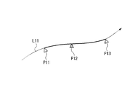
- FIG. 4 is an explanatory diagram illustrating an example of a travel route of the vehicle.
- a line L11 indicates a travel route of a certain vehicle. This travel route is indicated by trip data.
- Points P11 and P13 indicate monitoring locations stored as monitoring execution condition candidates.
- the point P11 is a point where the vehicle is actually monitored by the monitoring subsystem 400.
- the information that the point P11 is the point where the vehicle is monitored is the vehicle monitoring transmitted from the accounting server 200 to the communication unit 110 based on the monitoring result in the monitoring subsystem 400 monitored at the point P11. Obtained based on information.
- point P13 is a monitoring execution condition candidate
- the vehicle is not monitored when the vehicle travels on the line L11, and is assumed to be a future monitoring location candidate.
- a point P12 indicates a charging point where charging is performed. Information related to the charging performed at point P12 is acquired based on the charging information generated by communication with the vehicle-mounted device 310 and transmitted from the charging server 200 to the communication unit 110.
- a point P11 that has been actually monitored, a charging point P12, and a point P13 that is a candidate for a monitoring location pass in this order.
- the vehicle is monitored by the monitoring subsystem 400 at the point P11, the charging process is performed by passing through the charging point P12, and the vehicle passes through the point P13 that is a candidate for the monitoring location.
- the points that are candidates for the monitoring location are not monitored in order to facilitate the explanation.
- the present invention is not limited to this. Even if monitoring has been performed in the past, if it is necessary to consider again as a monitoring location candidate, a location that has been monitored in the past may be selected as a monitoring location candidate. The same applies to the example of FIG. 5 described later.
- the monitoring efficiency varies depending on the arrangement and time distribution of the monitoring subsystem 400 determined by the monitoring execution conditions. For example, it is effective if a monitoring subsystem 400 is further installed in another monitoring location immediately after the monitoring location where the monitoring subsystem 400 is installed, and monitoring is performed, and only the same vehicle as the previous monitoring execution condition passes. Cannot monitor. Therefore, the traffic degree information generation unit 191 does not simply count the number of vehicles passing by each monitoring place, but assigns a score according to the situation of the vehicle when passing through the monitoring place, and sums the score for each monitoring place. , Generate traffic degree information.
- the traffic level information generation unit 191 assigns a larger score as the total amount of charge since the vehicle has been monitored last time is larger.
- the traffic degree information generation unit 191 uses, for example, a large amount of billing at the billing point P12 that has passed since receiving monitoring at the monitoring location P11 as the previous monitoring as a score at the monitoring location P13. A score of a size corresponding to the size.
- the traffic degree information generation unit 191 receives the previous monitoring, such as assigning a score based on the travel distance of the vehicle after receiving the previous monitoring or the elapsed time since receiving the previous monitoring. Scores may be assigned based on criteria other than the billing amount. Further, a score may be assigned based on a plurality of parameters selected from a billing amount, a travel distance, an elapsed time, and the like. In this case, the plurality of parameters may be added after being scored, or the result of multiplication by multiplication may be scored, and a method for obtaining the score is appropriately set.
- FIG. 5 is an explanatory diagram illustrating an example of travel routes of a plurality of vehicles passing through the same monitoring place.
- a line L21 indicates a travel route of a certain vehicle
- a line L22 indicates a travel route of another certain vehicle.
- Points P21 and P22 indicate charging points, respectively.
- Point P23 indicates a monitoring location that is not monitored by the monitoring subsystem 400 and is a candidate in the future.
- the traffic degree information generation unit 191 calculates a score by a vehicle traveling on the line L21 and a score by a vehicle traveling on the line L22. That is, the traffic level information generation unit 191 first calculates a score from the charge amount at the charge point P21 for the vehicle traveling on the line L21.
- the traffic level information generation unit 191 calculates a score from the charge amount at the charge point P22 for the vehicle traveling on the line L22. Then, the traffic degree information generation unit 191 calculates the sum of the scores of the vehicles traveling on each of the lines L11 and L12 passing through the monitoring place P23 as the score of the monitoring place P23. As described above, the traffic degree information generation unit 191 calculates a score for each vehicle passing through the monitoring place for each monitoring place, and generates a degree of traffic information by adding the scores.
- the traffic level information generation unit 191 stores, as traffic level information, a score for each monitoring location that is a monitoring execution condition that indicates the level of traffic of the vehicle to be monitored in association with the monitoring location. In this way, map information may be generated.
- the candidate selection unit 192 selects one or more candidates from a plurality of candidates including at least one of a location where the vehicle is monitored and a time when the vehicle is monitored based on the degree of traffic information. For example, the candidate selection unit 192 totals the scores calculated by the traffic degree information generation unit 191 for the monitoring execution condition candidates for each combination of the monitoring execution condition candidates stored in the storage unit 180, and obtains the highest score. Choose a higher combination.
- FIG. 6 is a flowchart illustrating an example of a processing procedure in which the monitoring plan evaluation server device 100 selects at least one of a plurality of monitoring location candidates that are monitoring execution condition candidates. For example, when a user operation for instructing selection of the monitoring execution condition candidate information is performed, the monitoring plan evaluation server apparatus 100 performs the processing illustrated in FIG. In the process of FIG. 6, the communication unit 110 acquires trip data and billing information from the billing server device 200 (step S101).
- the traffic degree information generation unit 191 may calculate the billing amount from the trip data.
- the storage unit 180 stores in advance the position of the charging point and the charging amount for each vehicle type, and the traffic level information generation unit 191 calculates the charging amount based on the position and vehicle type of the vehicle indicated by the trip data. calculate.
- the traffic level information generation unit 191 can easily cope with addition, deletion, or change of arrangement of charge points, change of charge amount, and the like.
- the traffic degree information generating unit 191 associates the charging information obtained in step S101 with the trip data obtained in step S101 based on the vehicle-mounted device ID and the date and time of charging (step S102). As a result, it is possible to grasp the place, timing, and amount of money charged in the travel indicated by the trip data.
- the traffic level information generation unit 191 associates the monitoring location indicated in the monitoring execution condition candidate information with the trip data based on the position of the monitoring location (step S103). As a result, in the travel indicated by the trip data, it is possible to grasp the location and timing of passing through the monitoring location.
- the traffic degree information generation unit 191 calculates a score when passing through the monitoring place (step S104). Specifically, the traffic level information generation unit 191 determines the monitoring location for each of the monitoring location passages indicated by the trip data by the association in step S103, based on the total amount charged from the previous monitoring location passage. Calculated as the score assigned to Next, the degree-of-passage information generation unit 191 sums up the scores calculated in step S104 for each monitoring place, and calculates the score of each monitoring place as the degree-of-passage information (step S105).
- the candidate selection unit 192 selects a monitoring place based on the score indicating the degree of traffic information obtained in step S105 (step S106).
- one or more monitoring locations may be selected.
- the designated number is selected from the top of the score indicating the degree of traffic information.
- the monitoring condition candidate may be composed of a combination of a plurality of monitoring locations, a plurality of such combinations may be stored, and one or a plurality of sets may be selected.
- the traffic level information generation unit 191 calculates the sum of the scores of all the monitoring locations included in the combination of the monitoring locations as the score of the combination, and selects the combination of the monitoring locations with a high score.
- the display unit 120 displays the selection result in step S106 (step S107). Then, the process of FIG. 6 is complete
- the traffic level information generation unit 191 may generate traffic level information with reference to other information in addition to the score obtained from the trip data.
- the traffic degree information generation unit 191 may generate the traffic degree information in consideration of an evaluation value for the result of monitoring actually performed at the monitoring place, in the above-described score. For example, for a vehicle having a history of fraud, an evaluation value may be given and added to the above score, or an evaluation value may be given and multiplied by the above score. In addition, the evaluation value may be changed based on the time since the fraud was performed and the travel distance even in a vehicle having a history of fraud. Furthermore, instead of obtaining a score based on at least one of the elapsed time, mileage, and billing amount since the monitoring was performed, the evaluation value itself obtained only from the history of fraud may be used as the score.
- the communication unit 110 acquires trip data and vehicle monitoring information of each vehicle for a plurality of vehicles. Then, the traffic level information generation unit 191 considers the monitoring result of each vehicle obtained from the vehicle monitoring information, and determines the level of traffic of the vehicle that should be monitored at the monitoring location that is the condition indicated by each monitoring performance condition candidate. The degree of traffic information shown can be generated. Such traffic level information can provide information for predicting a monitoring place where the monitoring should be carried out, that is, the vehicle with high probability that the vehicle-related fraud has been performed can be efficiently detected. In addition, when the monitoring time is included as a condition indicated by the monitoring execution condition candidate, information for predicting a monitoring time that can efficiently detect a vehicle having a high probability that the vehicle fraud has been performed at any monitoring time Can be provided.
- the candidate selection unit 192 selects one or more monitoring execution condition candidates from a plurality of monitoring execution condition candidates based on the traffic degree information generated by the traffic degree information generation unit 191.
- the operator of the automatic billing system 1 installs the monitoring subsystem 400 so as to monitor the candidate consisting of at least one of the monitoring location and the monitoring time as the monitoring execution condition candidate selected by the candidate selection unit 192, It is possible to efficiently detect a vehicle in which fraud has occurred, such as a vehicle not equipped with the vehicle-mounted device 310 or a vehicle equipped with the inappropriate vehicle-mounted device 310.
- the traffic level information generation unit 191 may generate map information including information indicating the level of traffic of the vehicle to be monitored as the traffic level information. Thereby, the operator of the automatic billing system 1 determines the place and time for monitoring while confirming on the map a point where it is expected that the vehicle not equipped with the vehicle-mounted device 310 can be efficiently detected. can do.
- the traffic level information generation unit 191 extracts at least one of the monitoring location and the monitoring time at which the vehicle was last monitored based on the vehicle monitoring information, and displays the travel history indicated by the trip data.
- the monitoring execution condition candidate that passed after the monitoring location or the monitoring time that was last monitored based on the extracted time is extracted, and the time from when the vehicle was last monitored until the vehicle passes through the extracted monitoring execution condition candidate
- the traffic degree information is generated based on at least one of the interval, the travel distance, and the billing amount.
- the traffic level information generation unit 191 differs according to at least one of a time interval, a travel distance, and a billing amount from when the vehicle is last monitored until the vehicle passes through the extracted monitoring execution condition candidates. Traffic degree information indicating the degree can be generated.
- the condition indicated by the applicable monitoring condition candidate becomes longer as the time elapsed since the monitoring is performed, the vehicle travels a long distance, or the more vehicles that are charged for a large amount of traffic pass. Therefore, it can be evaluated that the vehicle to be monitored is a passing condition, and the time interval, travel distance, and billing amount can be taken into account when determining the monitoring execution condition.
- the traffic degree information generation unit 191 obtains at least a charge amount from when the vehicle was last monitored until the vehicle passes in the extracted monitoring execution condition candidate, and in the monitoring execution condition candidate You may make it produce
- the traffic level information generation unit 191 can present a location or time suitable for monitoring to prevent or detect a large amount of billing escape. For this reason, for example, the operator of the automatic billing system can efficiently perform monitoring for preventing or detecting expensive billing evasion by performing monitoring at the place or time.
- the trip data and vehicle monitoring information used by the traffic degree information generating unit 191 are actually measured data acquired from the vehicle-mounted device mounted on the actually traveling vehicle in the present embodiment, but are not limited to the actually measured data.
- the traffic degree information generation unit 191 causes a virtual vehicle to travel by simulation.
- the travel degree information may be generated using trip data and vehicle monitoring information obtained as monitored.
- a program for realizing all or part of the functions of the control unit 190 is recorded on a computer-readable recording medium, and the program recorded on the recording medium is read into a computer system and executed. You may perform the process of.
- the “computer system” includes an OS and hardware such as peripheral devices. Further, the “computer system” includes a homepage providing environment (or display environment) if a WWW system is used.
- the “computer-readable recording medium” includes a portable medium such as a flexible disk, a magneto-optical disk, and a compact disk, and a non-transitory storage medium represented by a storage device such as a hard disk built in a computer system. .
- the “computer-readable recording medium” dynamically holds a program for a short time like a communication line when transmitting a program via a network such as the Internet or a communication line such as a telephone line.
- the program may be a program for realizing a part of the functions described above, and may be a program capable of realizing the functions described above in combination with a program already recorded in a computer system.
- the present invention includes a vehicle monitoring condition information that indicates at least one of a monitoring location and a monitoring time of a vehicle, and information on a vehicle that is a monitoring target at the monitoring location or the monitoring time, and indicates a monitoring result of the vehicle.
- a vehicle monitoring information acquisition unit that acquires information; a movement information acquisition unit that acquires vehicle movement information related to movement of each vehicle for a plurality of vehicles; and a monitoring execution condition candidate that includes at least one of a location and a time for monitoring the vehicle Evaluation of a monitoring plan, comprising: a traffic degree information generating unit that generates traffic degree information indicating the degree of traffic of a vehicle to be monitored based on the vehicle movement information and the vehicle monitoring information, under the conditions shown About the system.
- the present invention includes monitoring execution condition information indicating at least one of a vehicle monitoring location and a monitoring time, and information on the vehicle monitored at the monitoring location or the monitoring time, and shows a vehicle monitoring result.
- a vehicle monitoring information acquisition step for acquiring vehicle monitoring information
- a movement information acquisition step for acquiring vehicle movement information related to the movement of each vehicle
- a monitoring execution condition comprising at least one of the location and time for monitoring the vehicle.
- a degree-of-traffic-degree information generating step for generating degree-of-traffic information indicating the degree of traffic of the vehicle to be monitored based on the conditions indicated by the candidates, based on the vehicle movement information and the vehicle monitoring information. It relates to the evaluation method. According to the above-described monitoring plan evaluation system and evaluation method, it is possible to provide information for predicting at least one of a location and a time at which a vehicle not equipped with a vehicle-mounted device can be efficiently detected.
Landscapes
- Business, Economics & Management (AREA)
- Physics & Mathematics (AREA)
- General Physics & Mathematics (AREA)
- Engineering & Computer Science (AREA)
- Human Resources & Organizations (AREA)
- Finance (AREA)
- Economics (AREA)
- Tourism & Hospitality (AREA)
- Strategic Management (AREA)
- Marketing (AREA)
- General Business, Economics & Management (AREA)
- Theoretical Computer Science (AREA)
- Entrepreneurship & Innovation (AREA)
- Analytical Chemistry (AREA)
- Chemical & Material Sciences (AREA)
- Development Economics (AREA)
- Educational Administration (AREA)
- Health & Medical Sciences (AREA)
- Primary Health Care (AREA)
- General Health & Medical Sciences (AREA)
- Operations Research (AREA)
- Quality & Reliability (AREA)
- Game Theory and Decision Science (AREA)
- Computer Networks & Wireless Communication (AREA)
- Remote Sensing (AREA)
- Radar, Positioning & Navigation (AREA)
- Computer Security & Cryptography (AREA)
- Traffic Control Systems (AREA)
- Devices For Checking Fares Or Tickets At Control Points (AREA)
Abstract
Description
例えば、特許文献1には、GPS(Global Positioning System、全地球測位システム)によって通行車両の位置標定を行ない、課金条件と車両の位置情報とに基づいて課金処理を行う料金徴収用車載器が記載されている。
このような、車載器が車両の位置情報に基づいて課金処理を行う方式では、路側設備がない場所でも車載器が自律的に課金処理を行うことが可能である。従って、この方式では、路側設備を削減することができ、また、課金条件の設定や変更を柔軟に行うことができる。
特に、車載器が自身の位置に基づいて自律的に課金処理を行う場合、外部で課金処理を行わないので、車載器を車両から取り外す不正が行われると、課金処理時に外部から不正を検出することができない。従って、車載器を搭載すべき状況(例えば、全車に搭載が義務付けられている状況)にもかかわらず、車載器を取り外す不正が行われてしまうと、当該不正を行われた車両では、必要な課金処理が行われないこととなってしまう。このため、車載器が自律的に課金処理を行う場合には、車両を監視して不正車両を検出し取り締まることの必要性がさらに高まっている。
しかしながら、上記車載器の不正など、取り締まるべき不正が行われている車両の通行状況は場所や時刻によって異なると考えられ、取り締まりを行うための監視を行う場所や時刻によって不正が行われている車両の検出状況は異なると考えられる。そこで、不正が行われている車両を効率よく検出できる場所及び時刻の少なくとも一方を予測できることが望まれる。
ここで、監視を実施すべき車両とは、車両に関する不正が行われた蓋然性が高かまっているため、監視の必要性が高まっている車両のことである。
これにより、候補選択部が選択した場所または時刻に従って監視用のシステムを設置することで、不正が行われた車両の検出を効率よく行うことができる。
これにより、車載器を搭載していない車両の検出を効率よく行うことができると予想される地点を、通行程度情報を構成する地図情報で確認しながら、監視を行う場所や時間を決定することができる。
これにより、通行程度情報生成部は、高額の課金逃れを防止または検出するための監視に適した場所または時刻を提示することができる。このため、例えば自動課金システムの運用者は、当該場所または時刻にて監視を行うことで、高額の課金逃れを防止または検出するための監視を効率よく行うことができる。
以下、本発明の実施形態を説明するが、以下の実施形態は請求の範囲にかかる発明を限定するものではない。また、実施形態の中で説明されている特徴の組み合わせの全てが発明の解決手段に必須であるとは限らない。
図1は、本発明の一実施形態における自動課金システムの機能構成を示す概略ブロック図である。同図において、自動課金システム1は、監視計画評価用サーバ装置100と、課金用サーバ装置200と、監視用サブシステム400とを備える。監視計画評価用サーバ装置100は、通信部110と、表示部120と、記憶部180と、制御部190とを備える。制御部190は、通行程度情報生成部191と、候補選択部192とを備える。本実施形態で、監視用サブシステム400は、課金用サーバ通信装置410と、カメラ420と、DSRC(Dedicated Short Range Communication)通信装置430と、制御装置490とを備える。
また、課金用サーバ装置200は、車載器310が搭載された車両300のユーザに対して、車載器を利用して課金処理をするために、車載器310との間で通信を行う通信手段を有する。当該通信手段としては例えば携帯電話通信網などを利用した広域通信が可能な手段が挙げられるが、これに限らない。また、監視用サブシステム400におけるDSRC通信装置430は、狭域通信が可能な手段であり、監視用サブシステム400が設置された位置近傍の監視ポイントを通行する複数の車両300の各々が備える車載器310と通信を行う。なお、監視用サブシステム400が車載器310と通信を行う手段として、DSRC通信装置430は一例であり、例えば広域通信が可能な手段としても良い。
自動課金システム1による課金では、車載器310が、課金条件が成立したことを検出すると課金処理を行う。課金条件の例として、車両が特定の場所を走行したことを挙げることができるが、これに限らない。例えば、課金条件が、車両が特定の時間帯に特定の場所を走行したことであるなど、時刻に関する条件を含んでいてもよい。また、特定のエリア内で、所定の距離ごとに課金するなど、距離に関する条件を含んでいてもよい。
ここでいう車両とは、自動車や二輪車など、道路を走行する乗り物である。また、ここでいう場所は、道路、または、道路の区間であってもよいし、複数の道路の少なくとも一部を含む区域であってもよいし、地点であってもよい。ここでいう地点は、点であってもよいし、道路の幅方向の線であってもよい。
図2は、課金情報のデータ構造の例を示す説明図である。同図において、課金情報は表形式のデータとして構成されており、各行において、車載器IDと、課金位置と、課金時刻と、課金内容とが対応付けられている。ここでいう車載器IDとは、車載器を識別するための情報である。
かかるデータ構造により、課金情報において、どの車載器が搭載された車両に対してどこの課金ポイントでいつ、幾らの課金が行われたかが示されている。
図3は、トリップデータのデータ構造の例を示す説明図である。同図において、トリップデータは表形式のデータとして構成されており、各行において、車載器IDと、走行位置と、走行時刻とが対応付けられている。かかるデータ構造により、トリップデータにおいて、どの車載器が搭載された車両がどこをいつ走行したかが示されている。
また、車載器310は、監視用サブシステム400からの問い合わせに対して、車載器310自らが車両に搭載されていることを示す情報を監視用サブシステム400へ送信する。車載器310自らが車両に搭載されていることを示す情報として、車載器IDを用いることができるがこれに限らない。
監視用サブシステム400は、本実施形態では、車載器310を搭載していない車両を検出する。以下では、全ての車両に車載器310を搭載することが義務付けられている場合を例に説明するが、本実施形態の適用範囲はこれに限らない。例えば、課金ポイントを通過する全車両に車載器310を搭載することが義務付けられている場合、監視用サブシステム400が、課金ポイントを通過した直後の車を対象に、車載器310を搭載していない車両を検出するようにしてもよい。ここでいう課金ポイントとは、課金が行われる場所である。
具体的には、制御装置490は、カメラ420の画像に車両の像が含まれるか否かを判定することで、監視ポイントに位置する車両の有無を判定する。そして、制御装置490は、画像に車両の像が含まれている場合には、当該画像に含まれている車両のナンバープレートをパターン認識し、認識したナンバープレートに表示された車両ナンバーをOCR処理などによって抽出する。また、監視ポイントに位置する車両が存在すると判定した場合、制御装置490は、DSRC通信装置430によって車載器310と通信が確立したか否かによって、当該車両が車載器310を搭載しているか否かを判定する。そして、制御装置490は、DSRC通信装置430と車載器310との通信が所定時間確立しなかった場合には、車載器310を搭載していない不正を行っている車両を検出したことを示す情報と当該車両の車両ナンバーとによって、監視対象となった車両の情報を構成する。そして、制御装置490は、該監視用サブシステム400で監視を行った車両300の監視場所及び監視時刻に関する監視実施条件情報と、当該監視対象となった車両の情報とを含む車両監視情報を、課金用サーバ通信装置410を介して課金用サーバ装置200へ送信する。
このように、監視用サブシステム400は、監視場所に設置して、カメラ420やDSRC通信装置420により車両の情報を収集することで、走行する車両の客観的な走行の事実を収集することが可能となり、不正が行われている車両を監視するに際しての証拠性を高めることが可能となる。また、監視用サブシステム400は、課金用サーバ通信装置410により課金用サーバ装置200へ収集した車両の情報を送信することができることで、収集した車両の情報の蓄積、分析を効率良く行うことが可能となる。
また、監視用サブシステム400が、特定の監視ポイント専用に、当該監視ポイント近傍の特定の位置に設置されていてもよい。あるいは、監視用サブシステム400が車両に設置されているなど、移動可能に設置されていてもよい。
監視計画評価用サーバ装置100は、監視計画の評価システムの例に該当する。但し、監視計画の評価システムは、1台の装置として構成されていてもよいし、複数の装置を組み合わせて構成されていてもよい。
表示部120は、例えば液晶パネルなどの表示画面を有し、静止画像や動画像やテキスト(文字)など各種画像を表示する。特に、表示部120は、車両が車載器を搭載しているか否かの監視を行う場所を決定するための情報を表示する。
通行程度情報生成部191は、監視実施条件候補の示す条件における、監視を実施すべき車両の通行の程度を示す通行程度情報を、車両監視情報及びトリップデータに基づいて生成する。監視実施条件候補が監視場所である場合には、監視実施条件候補を示す各監視場所を監視実施条件として、通行程度情報は、当該監視場所を、監視を実施すべき車両がどの程度通行しているかの程度を示すものとなる。また、監視実施条件候補が監視時間である場合には、監視実施条件候補を示す監視時間を監視実施条件として、通行程度情報は、当該監視時間に、監視を実施すべき車両がどの程度通行しているかの程度を示すものとなる。監視実施条件候補が監視場所及び監視時間である場合には、監視実施条件候補を示す監視場所及び監視時間の各組み合わせを監視実施条件として、通行程度情報は、当該監視場所及び監視時間の組み合わせにおいて、監視を実施すべき車両がどの程度通行しているかの程度を示すものとなる。
より具体的には、通行程度情報生成部191は、通信部110が取得する車両監視情報及びトリップデータに基づいて、監視実施条件候補を通過した車両によって当該監視実施条件候補に与えられるスコアを算出する。本実施形態では、このスコアが高いほど、ある監視実施条件候補、すなわち、ある監視場所や監視時間が、不正車両の監視に適していることを示す。
図4は、車両の走行経路の例を示す説明図である。同図において、線L11は、ある車両の走行経路を示す。この走行経路は、トリップデータにて示される。また、点P11、P13は、それぞれ監視実施条件候補として記憶されている監視場所を示す。ここで、点P11は、実際に監視用サブシステム400により車両の監視が行われたポイントとする。点P11が車両の監視が行われたポイントであるとの情報は、点P11で監視を行った監視用サブシステム400における監視結果に基づいて課金用サーバ200から通信部110に送信された車両監視情報に基づいて取得される。また、点P13は、監視実施条件候補であるものの、線L11を車両が走行した時点で車両の監視が行われておらず今後監視場所の候補となるポイントとする。また、点P12は、課金が行われる課金ポイントを示す。点P12で行われた課金に関する情報は、車載器310との通信により生成されて課金用サーバ200から通信部110に送信された課金情報に基づいて取得される。
図5の例において、通行程度情報生成部191は、線L21を走行する車両によるスコアと、線L22を走行する車両によるスコアとを演算する。すなわち、通行程度情報生成部191は、まず、線L21を走行する車両について、課金ポイントP21における課金額からスコアを演算する。さらに、通行程度情報生成部191は、線L22を走行する車両について、課金ポイントP22における課金額からスコアを演算する。そして、通行程度情報生成部191は、監視場所P23のスコアとして、当該監視場所P23を通過する線L11及線L12のそれぞれを走行する車両のスコアを合計したものを算出する。このように、通行程度情報生成部191は、監視場所別に、当該監視場所を通過する車両ごとにスコアを算出し、これらスコアを合計して通行程度情報を生成する。
なお、通行程度情報生成部191が、通行程度情報として、監視を実施すべき車両の通行の程度を示すことになる監視実施条件となる監視場所ごとのスコアを、監視場所と対応付けて記憶させるようにして地図情報を生成するようにしてもよい。
次に、図6を参照して監視計画評価用サーバ装置100の動作について説明する。
図6は、監視計画評価用サーバ装置100が監視実施条件候補である監視場所の複数の候補から少なくとも一つを選択する処理手順の例を示すフローチャートである。監視計画評価用サーバ装置100は、例えば、監視実施条件候補情報の選択を指示するユーザ操作が行われると、同図の処理を行う。
図6の処理において、通信部110は、トリップデータと課金情報とを課金用サーバ装置200から取得する(ステップS101)。
次に、通行程度情報生成部191は、監視実施条件候補情報に示される監視場所と、トリップデータとを、監視場所の位置に基づいて対応付ける(ステップS103)。これにより、トリップデータに示される走行において、監視場所を通過した場所やタイミングを把握可能になる。
次に通行程度情報生成部191は、ステップS104で算出したスコアを監視場所別に合計して、各監視場所のスコアを通行程度情報として算出する(ステップS105)。
そして、表示部120が、ステップS106での選択結果を表示する(ステップS107)。
その後、図6の処理を終了する。
これにより、自動課金システム1の運用者は、候補選択部192が選択した監視実施条件候補となる監視場所及び監視時刻の少なくとも一方からなる候補を監視するよう監視用サブシステム400を設置して、車載器310を搭載していない車両や不適正な車載器310を搭載している車両などの不正が行われた車両の検出を効率よく行うことができる。
これにより、自動課金システム1の運用者は、車載器310を搭載していない車両の検出を効率よく行うことができると予想される地点を地図で確認しながら、監視を行う場所や時間を決定することができる。
これにより、通行程度情報生成部191は、車両が最後に監視されてから、抽出された監視実施条件候補を車両が通過するまでの時間間隔、走行距離及び課金額の少なくとも一つに応じて異なる程度を示す通行程度情報を生成することができる。このため、監視が行われてからの時間が経過し、長い距離を走行し、または、高額の課金が行われている車両が多く通行しているほど、該当する監視実施条件候補が示す条件を、監視を実施すべき車両が通行している条件であると評価することができ、監視実施条件を決定する際に上記時間間隔、走行距離、課金額を考慮することができる。
これにより、通行程度情報生成部191は、高額の課金逃れを防止または検出するための監視に適した場所または時刻を提示することができる。このため、例えば自動課金システムの運用者は、当該場所または時刻にて監視を行うことで、高額の課金逃れを防止または検出するための監視を効率よく行うことができる。
また、「コンピュータシステム」は、WWWシステムを利用している場合であれば、ホームページ提供環境(あるいは表示環境)も含むものとする。
また、「コンピュータ読み取り可能な記録媒体」とは、フレキシブルディスク、光磁気ディスク、コンパクトディスク等の可搬媒体、コンピュータシステムに内蔵されるハードディスク等の記憶装置に代表される非一時的記憶媒体を含む。さらに「コンピュータ読み取り可能な記録媒体」とは、インターネット等のネットワークや電話回線等の通信回線を介してプログラムを送信する場合の通信線のように、短時間の間、動的にプログラムを保持する一時的記憶媒体、及びサーバやクライアントとなるコンピュータシステム内部の揮発性メモリのように、一定時間プログラムを保持している非一時的記憶媒体を含むものとする。また上記プログラムは、前述した機能の一部を実現するためのものであっても良く、さらに前述した機能をコンピュータシステムにすでに記録されているプログラムとの組み合わせで実現できるものであってもよい。
また、本発明は、車両の監視場所及び監視時刻の少なくとも一方を示す監視実施条件情報と、当該監視場所または監視時刻にて監視対象となった車両の情報とを含み、車両の監視結果を示す車両監視情報を取得する車両監視情報取得ステップと、複数の車両について、各車両の移動に関する車両移動情報を取得する移動情報取得ステップと、車両を監視する場所及び時刻の少なくとも一方からなる監視実施条件候補の示す条件における、監視を実施すべき車両の通行の程度を示す通行程度情報を、前記車両移動情報と前記車両監視情報とに基づいて生成する通行程度情報生成ステップと、を備える、監視計画の評価方法に関する。
上記した監視計画の評価システム及び評価方法によれば、車載器を搭載していない車両を効率よく検出できる場所及び時刻の少なくとも一方を予測するための情報を提供することができる。
100 監視計画評価用サーバ装置
110 通信部
120 表示部
180 記憶部
190 制御部
191 通行程度情報生成部
192 候補選択部
200 課金用サーバ装置
Claims (6)
- 車両の監視場所及び監視時刻の少なくとも一方を示す監視実施条件情報と、当該監視場所または監視時刻にて監視対象となった車両の情報とを含み、車両の監視結果を示す車両監視情報を取得する車両監視情報取得部と、
複数の車両について、各車両の移動に関する車両移動情報を取得する移動情報取得部と、
車両を監視する場所及び時刻の少なくとも一方からなる監視実施条件候補の示す条件における、監視を実施すべき車両の通行の程度を示す通行程度情報を、前記車両移動情報と前記車両監視情報とに基づいて生成する通行程度情報生成部と、
を備える、監視計画の評価システム。 - 前記通行程度情報に基づいて、複数の監視実施条件候補から1つ以上の監視実施条件候補を選択する候補選択部を備える、請求項1に記載の、監視計画の評価システム。
- 前記通行程度情報生成部は、前記通行程度情報として、監視を実施すべき車両の通行の程度を示す情報を含む地図情報を生成する、請求項1または請求項2に記載の、監視計画の評価システム。
- 前記通行程度情報生成部は、前記車両監視情報に基づいて車両が最後に監視された監視場所及び監視時刻の少なくとも一方を抽出するとともに、前記車両移動情報にて示される走行履歴に基づいて前記最後に監視された監視場所または監視時刻よりも後に通過した前記監視実施条件候補を抽出し、前記車両が最後に監視されてから、抽出された前記監視実施条件候補において車両が通過するまでの時間間隔、走行距離及び課金額の少なくとも一つに基づいて前記通行程度情報を生成する、請求項1から3のいずれか一項に記載の、監視計画の評価システム。
- 前記通行程度情報生成部は、前記車両が最後に監視されてから、抽出された前記監視実施条件候補において車両が通過するまでの課金額を少なくとも求め、当該監視実施条件候補において通過する車両の前記課金額が大きいほど、前記監視を実施すべき車両の通行の程度が高くなるように、通行程度情報を生成する請求項4に記載の監視計画の評価システム。
- 車両の監視場所及び監視時刻の少なくとも一方を示す監視実施条件情報と、当該監視場所または監視時刻にて監視対象となった車両の情報とを含み、車両の監視結果を示す車両監視情報を取得する車両監視情報取得ステップと、
複数の車両について、各車両の移動に関する車両移動情報を取得する移動情報取得ステップと、
車両を監視する場所及び時刻の少なくとも一方からなる監視実施条件候補の示す条件における、監視を実施すべき車両の通行の程度を示す通行程度情報を、前記車両移動情報と前記車両監視情報とに基づいて生成する通行程度情報生成ステップと、
を備える、監視計画の評価方法。
Priority Applications (7)
| Application Number | Priority Date | Filing Date | Title |
|---|---|---|---|
| PCT/JP2015/051090 WO2016113910A1 (ja) | 2015-01-16 | 2015-01-16 | 監視計画の評価システムおよび監視計画の評価方法 |
| US15/543,565 US11145140B2 (en) | 2015-01-16 | 2015-01-16 | System for evaluating monitoring plan, and method for evaluating monitoring plan |
| GB1711459.6A GB2548778A (en) | 2015-01-16 | 2015-01-16 | System for evaluating monitoring plan, and method for evaluating monitoring plan |
| SG11201705775WA SG11201705775WA (en) | 2015-01-16 | 2015-01-16 | System for evaluating monitoring plan, and method for evaluating monitoring plan |
| KR1020177017645A KR101895739B1 (ko) | 2015-01-16 | 2015-01-16 | 감시 계획의 평가 시스템 및 감시 계획의 평가 방법 |
| JP2016569205A JP6332884B2 (ja) | 2015-01-16 | 2015-01-16 | 監視計画の評価システムおよび監視計画の評価方法 |
| MYPI2017702555A MY185496A (en) | 2015-01-16 | 2015-01-16 | System for evaluating monitoring plan, and method for evaluating monitoring plan |
Applications Claiming Priority (1)
| Application Number | Priority Date | Filing Date | Title |
|---|---|---|---|
| PCT/JP2015/051090 WO2016113910A1 (ja) | 2015-01-16 | 2015-01-16 | 監視計画の評価システムおよび監視計画の評価方法 |
Publications (1)
| Publication Number | Publication Date |
|---|---|
| WO2016113910A1 true WO2016113910A1 (ja) | 2016-07-21 |
Family
ID=56405470
Family Applications (1)
| Application Number | Title | Priority Date | Filing Date |
|---|---|---|---|
| PCT/JP2015/051090 Ceased WO2016113910A1 (ja) | 2015-01-16 | 2015-01-16 | 監視計画の評価システムおよび監視計画の評価方法 |
Country Status (7)
| Country | Link |
|---|---|
| US (1) | US11145140B2 (ja) |
| JP (1) | JP6332884B2 (ja) |
| KR (1) | KR101895739B1 (ja) |
| GB (1) | GB2548778A (ja) |
| MY (1) | MY185496A (ja) |
| SG (1) | SG11201705775WA (ja) |
| WO (1) | WO2016113910A1 (ja) |
Cited By (1)
| Publication number | Priority date | Publication date | Assignee | Title |
|---|---|---|---|---|
| JP2023137883A (ja) * | 2022-03-18 | 2023-09-29 | 三菱重工機械システム株式会社 | 不正検知装置、不正検知システム、不正検知方法、及びプログラム |
Citations (3)
| Publication number | Priority date | Publication date | Assignee | Title |
|---|---|---|---|---|
| JPH09319904A (ja) * | 1996-05-31 | 1997-12-12 | Mitsubishi Heavy Ind Ltd | 料金収受システム及び料金徴収用車載機 |
| JP2002251641A (ja) * | 2001-02-26 | 2002-09-06 | Hitachi Ltd | 交通量管理・自動課金システム |
| JP2005352615A (ja) * | 2004-06-09 | 2005-12-22 | Hitachi Ltd | プローブカーを用いた交通量管理エリアの交通量制御システム及びプローブカー情報収集配信センタ |
Family Cites Families (15)
| Publication number | Priority date | Publication date | Assignee | Title |
|---|---|---|---|---|
| US7127413B1 (en) | 1998-01-23 | 2006-10-24 | Toyota Jidosha Kabushiki Kaisha | Charge processing device charge processing system and charge processing card |
| JP3454412B2 (ja) | 1998-02-13 | 2003-10-06 | アイシン精機株式会社 | 課金装置およびシステム |
| KR100423779B1 (ko) | 1998-10-09 | 2004-03-22 | 도요다 지도샤 가부시끼가이샤 | 과금장치 |
| JP3393598B2 (ja) | 1998-11-30 | 2003-04-07 | アイシン精機株式会社 | 車上課金装置 |
| KR20010070744A (ko) * | 2001-06-04 | 2001-07-27 | 김흥배 | 교통통제와 범죄차량 자동색출을 위한 차량자원 관리방법및 장치 |
| KR100919983B1 (ko) * | 2007-11-28 | 2009-10-05 | 한국도로공사 | 유료도로의 통행료 미납 및 불법차량 적발시스템 및 그제어방법 |
| KR101191908B1 (ko) * | 2011-06-29 | 2012-10-17 | 디비정보통신 주식회사 | 과속차량 단속용 무인 카메라의 구동방법 |
| US20140172521A1 (en) | 2011-07-29 | 2014-06-19 | Nec Corporation | Traffic Control System, Congestion Control Method, Information Processing Apparatus, and Control Method and Storage Medium Therefor |
| EP2615598B1 (en) * | 2012-01-11 | 2017-12-06 | Honda Research Institute Europe GmbH | Vehicle with computing means for monitoring and predicting traffic participant objects |
| US9111136B2 (en) * | 2012-04-24 | 2015-08-18 | Xerox Corporation | System and method for vehicle occupancy detection using smart illumination |
| US10726403B2 (en) * | 2012-06-22 | 2020-07-28 | Adityakumar A. Aggarwal | Centralized toll tracking, payment and monitoring system using geo location enabled devices |
| KR101192734B1 (ko) * | 2012-08-08 | 2012-10-18 | 디비정보통신 주식회사 | 위반차량 다빈도 진출입정보 알림시스템 및 그 방법 |
| EP2701133B1 (de) * | 2012-08-22 | 2015-11-18 | Kapsch TrafficCom AG | Verfahren und Vorrichtungen zur Bildaufnahme eines geschwindigkeitsübertretenden Fahrzeugs |
| EP2909815B1 (de) * | 2012-10-17 | 2017-12-20 | Toll Collect GmbH | Verfahren und einrichtungen zur verkehrsbedingten mauterhebung |
| ES2590907T3 (es) * | 2013-10-08 | 2016-11-24 | Kapsch Trafficcom Ag | Procedimiento para comprobar transacciones de peaje y componentes para ello |
-
2015
- 2015-01-16 KR KR1020177017645A patent/KR101895739B1/ko active Active
- 2015-01-16 US US15/543,565 patent/US11145140B2/en active Active
- 2015-01-16 WO PCT/JP2015/051090 patent/WO2016113910A1/ja not_active Ceased
- 2015-01-16 MY MYPI2017702555A patent/MY185496A/en unknown
- 2015-01-16 GB GB1711459.6A patent/GB2548778A/en not_active Withdrawn
- 2015-01-16 SG SG11201705775WA patent/SG11201705775WA/en unknown
- 2015-01-16 JP JP2016569205A patent/JP6332884B2/ja active Active
Patent Citations (3)
| Publication number | Priority date | Publication date | Assignee | Title |
|---|---|---|---|---|
| JPH09319904A (ja) * | 1996-05-31 | 1997-12-12 | Mitsubishi Heavy Ind Ltd | 料金収受システム及び料金徴収用車載機 |
| JP2002251641A (ja) * | 2001-02-26 | 2002-09-06 | Hitachi Ltd | 交通量管理・自動課金システム |
| JP2005352615A (ja) * | 2004-06-09 | 2005-12-22 | Hitachi Ltd | プローブカーを用いた交通量管理エリアの交通量制御システム及びプローブカー情報収集配信センタ |
Cited By (2)
| Publication number | Priority date | Publication date | Assignee | Title |
|---|---|---|---|---|
| JP2023137883A (ja) * | 2022-03-18 | 2023-09-29 | 三菱重工機械システム株式会社 | 不正検知装置、不正検知システム、不正検知方法、及びプログラム |
| JP7752554B2 (ja) | 2022-03-18 | 2025-10-10 | 三菱重工機械システム株式会社 | 不正検知装置、不正検知システム、不正検知方法、及びプログラム |
Also Published As
| Publication number | Publication date |
|---|---|
| JP6332884B2 (ja) | 2018-05-30 |
| GB201711459D0 (en) | 2017-08-30 |
| JPWO2016113910A1 (ja) | 2017-09-14 |
| KR20170088962A (ko) | 2017-08-02 |
| US20170372531A1 (en) | 2017-12-28 |
| SG11201705775WA (en) | 2017-08-30 |
| US11145140B2 (en) | 2021-10-12 |
| GB2548778A (en) | 2017-09-27 |
| KR101895739B1 (ko) | 2018-09-05 |
| MY185496A (en) | 2021-05-19 |
Similar Documents
| Publication | Publication Date | Title |
|---|---|---|
| JP6658088B2 (ja) | 情報処理装置、プログラム、及び地図データ更新システム | |
| US9460429B2 (en) | GPS-based toll collection system and method | |
| JP7400247B2 (ja) | 報告書作成支援システム、サーバ装置、及びコンピュータプログラム | |
| KR101836990B1 (ko) | 차량 사고 정보 수집 방법, 이를 위한 장치 및 차량 사고 정보 수집 시스템 | |
| EP2005405A1 (en) | Private, auditable vehicle positioning system and on-board unit for same | |
| JP5964981B2 (ja) | プローブ交通情報生成システム及びプローブ交通情報生成方法 | |
| US20190017832A1 (en) | Method and apparatus for providing recorded, anonymized routes | |
| JPH11120478A (ja) | 交通事故管理支援システム | |
| CN111008856A (zh) | 信息处理装置、信息处理系统以及广告投放方法 | |
| KR102205057B1 (ko) | 동일 차량 검출 장치, 요금 수수 설비, 동일 차량 검출 방법 및 프로그램 | |
| Jones et al. | Parkus 2.0: Automated cruise detection for parking availability inference | |
| KR20200053736A (ko) | 블록체인 기반의 통행료 징수 시스템 및 방법 | |
| JP2012198790A (ja) | 移動体位置推定サーバ | |
| JP2004038489A (ja) | 車両運転管理装置、システムおよび方法 | |
| JP5545780B2 (ja) | 車載装置、車両および路側機 | |
| JP2016143180A (ja) | 経路把握装置、車載器、および経路把握方法 | |
| JP6332884B2 (ja) | 監視計画の評価システムおよび監視計画の評価方法 | |
| WO2011158038A1 (en) | Tracking method | |
| JP5562756B2 (ja) | 不正車両監視システム、不正車両監視方法及びそのプログラム | |
| WO2015129002A1 (ja) | 地図作成システム及び地図作成方法 | |
| JP6369494B2 (ja) | 識別情報判定装置、識別情報判定システム、コンピュータプログラム及び識別情報判定方法 | |
| JP2023139618A (ja) | サーバ、監視方法、及びプログラム | |
| RU135827U1 (ru) | Мобильное устройство для контроля оплаты стоянки транспортных средств в зонах платной парковки | |
| JP6203499B2 (ja) | 地図作成システム及び地図作成方法 | |
| JP7750045B2 (ja) | 交通管理装置、交通管理システム、交通管理方法及びプログラム |
Legal Events
| Date | Code | Title | Description |
|---|---|---|---|
| 121 | Ep: the epo has been informed by wipo that ep was designated in this application |
Ref document number: 15877862 Country of ref document: EP Kind code of ref document: A1 |
|
| ENP | Entry into the national phase |
Ref document number: 2016569205 Country of ref document: JP Kind code of ref document: A |
|
| ENP | Entry into the national phase |
Ref document number: 20177017645 Country of ref document: KR Kind code of ref document: A |
|
| WWE | Wipo information: entry into national phase |
Ref document number: 15543565 Country of ref document: US |
|
| ENP | Entry into the national phase |
Ref document number: 201711459 Country of ref document: GB Kind code of ref document: A Free format text: PCT FILING DATE = 20150116 |
|
| WWE | Wipo information: entry into national phase |
Ref document number: 11201705775W Country of ref document: SG |
|
| NENP | Non-entry into the national phase |
Ref country code: DE |
|
| 122 | Ep: pct application non-entry in european phase |
Ref document number: 15877862 Country of ref document: EP Kind code of ref document: A1 |