WO2016113822A1 - 車両用電源制御装置 - Google Patents
車両用電源制御装置 Download PDFInfo
- Publication number
- WO2016113822A1 WO2016113822A1 PCT/JP2015/006417 JP2015006417W WO2016113822A1 WO 2016113822 A1 WO2016113822 A1 WO 2016113822A1 JP 2015006417 W JP2015006417 W JP 2015006417W WO 2016113822 A1 WO2016113822 A1 WO 2016113822A1
- Authority
- WO
- WIPO (PCT)
- Prior art keywords
- power supply
- supply unit
- voltage
- control device
- supplied
- Prior art date
- Legal status (The legal status is an assumption and is not a legal conclusion. Google has not performed a legal analysis and makes no representation as to the accuracy of the status listed.)
- Ceased
Links
Images

Classifications
-
- B—PERFORMING OPERATIONS; TRANSPORTING
- B60—VEHICLES IN GENERAL
- B60R—VEHICLES, VEHICLE FITTINGS, OR VEHICLE PARTS, NOT OTHERWISE PROVIDED FOR
- B60R16/00—Electric or fluid circuits specially adapted for vehicles and not otherwise provided for; Arrangement of elements of electric or fluid circuits specially adapted for vehicles and not otherwise provided for
- B60R16/02—Electric or fluid circuits specially adapted for vehicles and not otherwise provided for; Arrangement of elements of electric or fluid circuits specially adapted for vehicles and not otherwise provided for electric constitutive elements
- B60R16/03—Electric or fluid circuits specially adapted for vehicles and not otherwise provided for; Arrangement of elements of electric or fluid circuits specially adapted for vehicles and not otherwise provided for electric constitutive elements for supply of electrical power to vehicle subsystems or for
-
- Y—GENERAL TAGGING OF NEW TECHNOLOGICAL DEVELOPMENTS; GENERAL TAGGING OF CROSS-SECTIONAL TECHNOLOGIES SPANNING OVER SEVERAL SECTIONS OF THE IPC; TECHNICAL SUBJECTS COVERED BY FORMER USPC CROSS-REFERENCE ART COLLECTIONS [XRACs] AND DIGESTS
- Y02—TECHNOLOGIES OR APPLICATIONS FOR MITIGATION OR ADAPTATION AGAINST CLIMATE CHANGE
- Y02T—CLIMATE CHANGE MITIGATION TECHNOLOGIES RELATED TO TRANSPORTATION
- Y02T10/00—Road transport of goods or passengers
- Y02T10/80—Technologies aiming to reduce greenhouse gasses emissions common to all road transportation technologies
- Y02T10/92—Energy efficient charging or discharging systems for batteries, ultracapacitors, supercapacitors or double-layer capacitors specially adapted for vehicles
Definitions
- the present disclosure relates to a vehicle power supply control device.
- a vehicle power supply control device generally includes a standby power supply unit and a main power supply unit.
- the standby power supply is a power supply that is constantly supplied with battery power regardless of whether the engine is driven.
- the standby power supply unit mainly monitors whether or not the engine has been started.
- the main power supply unit is a power supply unit that is started by being supplied with battery power as a trigger that the start of the engine is detected by the standby power supply unit.
- the main power supply unit drives, for example, a 3.3 V system device or a 5 V system device mounted on the vehicle based on a battery power supply supplied after the engine is started.
- the present disclosure provides a vehicular power supply control device that can continue driving without shutting off the supply of power even when the voltage of the battery power supply decreases at the time of starting the engine.
- the standby power supply unit is a power supply unit that is constantly supplied with battery power regardless of whether the engine is driven, and monitors whether the engine is started.
- the main power supply unit starts when battery power is supplied, triggered by the start of the engine detected by the standby power supply unit.
- the booster boosts the lowered voltage to a threshold voltage or higher when the voltage of the battery power supplied to the main power supply decreases to a predetermined threshold voltage or lower when the engine is started. According to this configuration, even if the voltage of the battery power supply decreases when the engine is started, the boosted power that is boosted above the threshold voltage is supplied to the main power supply unit. Therefore, driving can be continued without interrupting the supply of power.
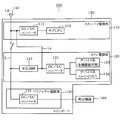
- FIG. 1 is a block diagram schematically illustrating a configuration example of a vehicle power supply control device according to the first embodiment.
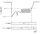
- FIG. 2 is a diagram illustrating an example of a variation state of the battery power supply at the time of starting the engine and an example of a driving state of the main power supply unit and the peripheral power supply unit.
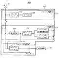
- FIG. 3 is a block diagram schematically showing a configuration example of the vehicle power supply control device according to the second embodiment.
- FIG. 4 is a block diagram schematically illustrating a configuration example of the vehicle power supply control device according to the third embodiment.
- a vehicle power supply control device 100 illustrated in FIG. 1 includes a standby power supply unit 110, a main power supply unit 120, and a peripheral power supply unit 130.
- the vehicle power supply control device 100 is simply referred to as a “power supply control device 100”.
- the power supply control device 100 is configured to drive the standby power supply unit 110, the main power supply unit 120, and the peripheral power supply unit 130 based on a battery power supply “+ B” supplied from, for example, a 12V in-vehicle battery 140.
- the standby power supply unit 110, the main power supply unit 120, and the peripheral power supply unit 130 are mounted on a common main board 150.
- the standby power supply unit 110 is a power supply unit that is constantly supplied with battery power “+ B” regardless of whether or not an engine (not shown) is driven, and includes a DC / DC converter 111, a sub CPU 112, and the like.
- the DC / DC converter 111 converts the power supply voltage of the battery power supply “+ B” supplied from the in-vehicle battery 140 into a predetermined voltage, for example, 3.3 V, and supplies it to the sub CPU 112.
- the sub CPU 112 monitors whether or not the engine has been started based on detecting whether an accessory switch or an ignition switch (not shown) is turned on / off.
- the sub CPU 112 When the sub CPU 112 detects that the engine has been started, the sub CPU 112 closes the power supply line L to the main power supply unit 120 and the peripheral power supply unit 130, and supplies the battery power “+ B to the main power supply unit 120 and the peripheral power supply unit 130. ".
- the main power supply unit 120 is a power supply unit that is started when the battery power supply “+ B” is supplied as a trigger that the standby power supply unit 110 has detected the start of the engine.
- the main power supply unit 120 includes a booster circuit 121, a DC / DC converter 122, device systems 123 and 124, and the like.
- the booster circuit 121 is an example of a booster. When the voltage of the battery power source “+ B” supplied from the in-vehicle battery 140 is equal to or higher than a predetermined threshold voltage Va, the booster circuit 121 supplies the power source to the DC / DC converter 122 as it is.
- the booster circuit 121 boosts the reduced voltage to the threshold voltage Va or higher. Then, the booster circuit 121 supplies the boosted power source boosted to the threshold voltage Va or higher to the DC / DC converter 122.
- the DC / DC converter 122 converts the power supply voltage supplied from the booster circuit 121 into a voltage suitable for driving the device systems 123 and 124 and supplies the converted voltage.
- the DC / DC converter 122 supplies the power converted to 3.3V to the device system 123 and supplies the power supplied to 5V to the device system 124.
- Devices included in the device systems 123 and 124 are driven based on a given power source.
- the device system 123 includes a device group that is driven by a drive voltage of 3.3V.
- Devices included in the device system 123 include, for example, a drive circuit for driving a driver of an SD card, a drive circuit for a CPU fan, and wireless communication that realizes Bluetooth (registered trademark) communication that is an example of a short-range wireless communication standard. Module drive circuit.
- the device system 124 includes a device group that is driven with a drive voltage of 5V.
- the device included in the device system 124 is, for example, a main CPU (not shown) that controls driving of various drive circuits included in the device system 123.
- the above-described threshold voltage Va can be appropriately changed and set, but it is preferable to set a value equal to or higher than the drive voltage of various devices driven by the main power supply unit 120.
- the threshold voltage Va is set to, for example, 7 V, which is a value higher than these voltage values. . Therefore, according to the power supply control device 100, for example, even when the voltage of the battery power supply “+ B” decreases when the engine is started, the DC / DC converter 122 for driving the device systems 123 and 124 has at least 7V. The above power is supplied.
- the peripheral power supply unit 130 is a power supply unit that drives the peripheral device 160 by being supplied with the battery power “+ B” as a trigger when the standby power supply unit 110 detects the start of the engine.
- the peripheral power supply unit 130 includes a DC / DC converter 131 and the like.
- the DC / DC converter 131 converts the power supply voltage of the battery power supply “+ B” supplied from the in-vehicle battery 140 into a voltage suitable for driving the peripheral device 160 and supplies the converted voltage.
- the peripheral device 160 is driven based on the power supplied from the DC / DC converter 131. In this case, the peripheral device 160 is provided outside the main board 150.
- peripheral device 160 for example, various devices such as a touch panel of a vehicle device such as a navigation device, a liquid crystal display, an in-vehicle microphone, an in-vehicle speaker, and an in-vehicle camera are conceivable.
- the power control device 100 when the engine is started, it is assumed that the voltage of the battery power source “+ B” of 12 V drops to a considerably low level, for example, 4.5 V.
- the power supply control device 100 even if the voltage of the battery power source “+ B” is lowered to 4.5V, that is, a level lower than 7V, the lowered voltage is boosted and the boosted power source of 7V or more becomes the main power source. Supplied to the unit 120. Therefore, even if the voltage of the battery power source “+ B” is lowered to a low level such as 4.5 V, the main power supply unit 120 can be kept on.
- the supply of the battery power “+ B” to the peripheral power supply unit 130 is turned off when the voltage of the battery power “+ B” is lower than 8 V, for example, and is returned to 8 V or higher. Is to be turned on.
- the power supply control device 100 even when the voltage of the battery power supply “+ B” decreases at the start of the engine, the boosted power boosted to the threshold voltage Va or higher is supplied to the main power supply unit 120. Therefore, it is possible to continue driving the device systems 123 and 124 without interrupting the supply of power.
- a value equal to or higher than the drive voltage of each device system 123, 124 driven by the main power supply unit 120 is set as the threshold voltage Va. Therefore, when the voltage of the battery power source “+ B” decreases, the boosted voltage exceeding the drive voltage of each device system 123, 124 can be supplied reliably, and the drive of each device system 123, 124 is more reliably continued. can do.
- the vehicle power supply control device 200 illustrated in FIG. 3 supplies the boosted power source boosted by the booster circuit 121 to the threshold voltage Va or higher, in addition to the main power source unit 120, and also to the standby power source unit 110 through the power supply line La It is the structure made to supply.
- the vehicle power supply control device 200 is simply referred to as a “power supply control device 200”.
- the booster circuit 121 supplies the generated boosted power to the DC / DC converter 111 of the standby power supply unit 110 via the power supply line La.
- the DC / DC converter 111 converts the boosted power supplied from the booster circuit 121 into a predetermined voltage, for example, 3.3 V, and supplies it to the sub CPU 112.
- the sub CPU 112 is driven based on the power supplied from the DC / DC converter 111.
- the power supply control device 200 even if the voltage of the battery power supply “+ B” decreases at the start of the engine, the boosted power boosted to the threshold voltage Va or higher is also supplied to the standby power supply unit 110. Therefore, it is possible to avoid the standby power supply unit 110 that should always be in the driving state from being turned off.
- the vehicle power supply control device 300 illustrated in FIG. 4 is configured to supply not only the main power supply unit 120 but also the peripheral power supply unit 130 via the power supply line Lb.
- the vehicle power supply control device 300 is simply referred to as “power supply control device 300”.
- the booster circuit 121 supplies the generated boosted power to the DC / DC converter 131 of the peripheral power supply unit 130 via the power supply line Lb.
- the DC / DC converter 131 converts the boosted power supplied from the booster circuit 121 into a voltage suitable for driving the peripheral device 160 and supplies the converted voltage.
- the peripheral device 160 is driven based on the power supplied from the DC / DC converter 131.
- the power supply control device 300 even if the voltage of the battery power supply “+ B” decreases when the engine is started, the boosted power boosted to the threshold voltage Va or higher is also supplied to the peripheral power supply unit 130. Therefore, it is possible to avoid the peripheral device 160 from being turned off.
- the device system driven by the main power supply unit 120 is not limited to the above-described 3.3V system or 5.5V system.
- various device systems such as a device system driven by a driving voltage of 1.8 V can be applied.
- the vehicle power supply control device may be configured such that the standby power supply unit 110, the main power supply unit 120, and the peripheral power supply unit 130 are mounted on different substrates.
- the vehicle power supply control device may be configured by combining the second embodiment and the third embodiment. That is, the vehicle power supply control device may be configured to supply the boosted power generated by the booster circuit 121 to both the standby power supply unit 110 and the peripheral power supply unit 130 in addition to the main power supply unit 120.
Landscapes
- Engineering & Computer Science (AREA)
- Mechanical Engineering (AREA)
- Charge And Discharge Circuits For Batteries Or The Like (AREA)
Abstract
車両用電源制御装置は、バッテリ電源が常時供給され、エンジンが始動されたか否かを監視するスタンバイ電源部(110)と、スタンバイ電源部がエンジンの始動を検知すると、バッテリ電源が供給されて始動するメイン電源部(120)と、エンジンの始動時においてメイン電源部に与えられるバッテリ電源の電圧が所定の閾値電圧以下に低下した場合に、低下した電圧を閾値電圧以上に昇圧する昇圧部(121)と、を備える。
Description
本出願は、2015年1月15日に出願された日本国特許出願2015-5904号に基づくものであり、その開示をここに参照により援用する。
本開示は、車両用電源制御装置に関する。
車両用の電源制御装置は、一般的に、スタンバイ電源部とメイン電源部を備える。スタンバイ電源部は、エンジンの駆動の有無に関わらずバッテリ電源が常時供給される電源部である。スタンバイ電源部は、主として、エンジンが始動されたか否かを監視する。一方、メイン電源部は、スタンバイ電源部によりエンジンの始動が検知されたことトリガとして、バッテリ電源が供給されて始動する電源部である。メイン電源部は、エンジンの始動後に供給されるバッテリ電源に基づいて、車両に搭載される例えば3.3V系のデバイスや5V系のデバイスを駆動する。
ところで、この種の電源制御装置においては、エンジンの始動時にバッテリ電源の電圧が低下することが想定される。そのため、このようなバッテリ電圧の低下に対応するための種々の技術が考えられている。例えば特許文献1には、バッテリ電源の電圧が10.5Vよりも低下した状態が所定時間以上継続した場合、または、バッテリ電源の電圧が8.5Vよりも低下した場合に、全システムに対する電源の供給を遮断する技術が開示されている。
エンジンの始動時においては、12Vのバッテリ電源の電圧が例えば4.5Vといったかなり低いレベルまで低下することが想定される。しかしながら、特許文献1に開示されている技術では、10.5Vあるいは8.5Vといった比較的高いレベルの電圧を基準として電源の供給を遮断する。そのため、電源供給が遮断されてしまう頻度が多くなるおそれがあり、ひいては、バッテリ電源の電圧復帰後の再起動処理の頻度が多くなる、および再起動までに時間がかかるおそれがある。
そこで、本開示は、エンジンの始動時においてバッテリ電源の電圧が低下したとしても、電源の供給を遮断することなく駆動を継続することができる車両用電源制御装置を提供する。
本開示の一例による車両用電源制御装置によれば、スタンバイ電源部は、エンジンの駆動の有無に関わらずバッテリ電源が常時供給される電源部であり、エンジンが始動されたか否かを監視する。メイン電源部は、スタンバイ電源部によりエンジンの始動が検知されたことをトリガとして、バッテリ電源が供給されて始動する。昇圧部は、エンジンの始動時においてメイン電源部に与えられるバッテリ電源の電圧が所定の閾値電圧以下に低下した場合に、その低下した電圧を閾値電圧以上に昇圧する。この構成によれば、エンジンの始動時においてバッテリ電源の電圧が低下したとしても、閾値電圧以上に昇圧した昇圧電源がメイン電源部に供給される。そのため、電源の供給を遮断することなく駆動を継続することができる。
本開示についての上記および他の目的、特徴や利点は、添付の図面を参照した下記の詳細な説明から、より明確になる。添付図面において、
図1は、第1実施形態に係る車両用電源制御装置の構成例を概略的に示すブロック図であり、
図2は、エンジンの始動時におけるバッテリ電源の変動状態の一例と、メイン電源部およびペリフェラル電源部の駆動状態の一例を示す図であり、
図3は、第2実施形態に係る車両用電源制御装置の構成例を概略的に示すブロック図であり、
図4は、第3実施形態に係る車両用電源制御装置の構成例を概略的に示すブロック図である。
以下、車両用電源制御装置に係る複数の実施形態について図面を参照しながら説明する。なお、各実施形態において実質的に同一の要素には同一の符号を付し、説明を省略する。
(第1実施形態)
図1に例示する車両用電源制御装置100は、スタンバイ電源部110、メイン電源部120、ペリフェラル電源部130を備える。以下、車両用電源制御装置100を、単に「電源制御装置100」と称する。電源制御装置100は、例えば12Vの車載バッテリ140から与えられるバッテリ電源「+B」に基づいて、スタンバイ電源部110、メイン電源部120、ペリフェラル電源部130を駆動する構成である。この場合、スタンバイ電源部110、メイン電源部120、ペリフェラル電源部130は、共通のメインボード150に実装されている。
図1に例示する車両用電源制御装置100は、スタンバイ電源部110、メイン電源部120、ペリフェラル電源部130を備える。以下、車両用電源制御装置100を、単に「電源制御装置100」と称する。電源制御装置100は、例えば12Vの車載バッテリ140から与えられるバッテリ電源「+B」に基づいて、スタンバイ電源部110、メイン電源部120、ペリフェラル電源部130を駆動する構成である。この場合、スタンバイ電源部110、メイン電源部120、ペリフェラル電源部130は、共通のメインボード150に実装されている。
スタンバイ電源部110は、図示しないエンジンの駆動の有無に関わらずバッテリ電源「+B」が常時供給される電源部であり、DC/DCコンバータ111、サブCPU112などを備える。DC/DCコンバータ111は、車載バッテリ140から与えられるバッテリ電源「+B」の電源電圧を所定電圧、例えば3.3Vに変換してサブCPU112に供給する。サブCPU112は、図示しないアクセサリスイッチまたはイグニッションスイッチのオン/オフを検知することに基づいて、エンジンが始動されたか否かを監視する。そして、サブCPU112は、エンジンが始動されたことを検知すると、メイン電源部120およびペリフェラル電源部130への電源供給ラインLを閉路して、メイン電源部120およびペリフェラル電源部130にバッテリ電源「+B」を供給する。
メイン電源部120は、スタンバイ電源部110によりエンジンの始動が検知されたことトリガとして、バッテリ電源「+B」が供給されて始動する電源部である。メイン電源部120は、昇圧回路121、DC/DCコンバータ122、デバイス系123,124などを備える。昇圧回路121は、昇圧部の一例である。昇圧回路121は、車載バッテリ140から与えられるバッテリ電源「+B」の電圧が所定の閾値電圧Va以上である場合には、その電源を、そのままDC/DCコンバータ122に供給する。しかし、昇圧回路121は、車載バッテリ140から与えられるバッテリ電源「+B」の電圧が所定の閾値電圧Vaよりも低い場合には、その低下した電圧を閾値電圧Va以上に昇圧する。そして、昇圧回路121は、閾値電圧Va以上に昇圧した昇圧電源をDC/DCコンバータ122に供給する。
DC/DCコンバータ122は、昇圧回路121から与えられる電源電圧を、各デバイス系123,124の駆動に適した電圧にそれぞれ変換して供給する。この場合、DC/DCコンバータ122は、3.3Vに変換した電源をデバイス系123に供給し、5Vに供給した電源をデバイス系124に供給する。各デバイス系123,124に含まれるデバイスは、与えられた電源に基づいて駆動する。
デバイス系123は、この場合、3.3Vの駆動電圧で駆動するデバイス群で構成されている。このデバイス系123に含まれるデバイスは、例えば、SDカードのドライバを駆動するための駆動回路、CPUファンの駆動回路、近距離無線通信規格の一例であるBluetooth(登録商標)通信を実現する無線通信モジュールの駆動回路などである。デバイス系124は、この場合、5Vの駆動電圧で駆動するデバイス群で構成されている。このデバイス系124に含まれるデバイスは、例えば、デバイス系123に含まれる各種の駆動回路の駆動を制御する図示しないメインCPUなどである。
上記した閾値電圧Vaは、適宜変更して設定可能であるが、メイン電源部120により駆動される各種デバイスの駆動電圧以上の値を設定することが好ましい。この場合、メイン電源部120により駆動される各種デバイスの駆動電圧は3.3Vおよび5.5Vであるから、閾値電圧Vaとしては、これらの電圧値以上の値である例えば7Vが設定されている。そのため、電源制御装置100によれば、例えばエンジンの始動時においてバッテリ電源「+B」の電圧が低下したとしても、各デバイス系123,124を駆動するためのDC/DCコンバータ122には、少なくとも7V以上の電源が供給される。
ペリフェラル電源部130は、スタンバイ電源部110によりエンジンの始動が検知されたことトリガとして、バッテリ電源「+B」が供給されて周辺機器160を駆動する電源部である。ペリフェラル電源部130は、DC/DCコンバータ131などを備える。DC/DCコンバータ131は、車載バッテリ140から与えられるバッテリ電源「+B」の電源電圧を周辺機器160の駆動に適した電圧に変換して供給する。周辺機器160は、DC/DCコンバータ131から与えられる電源に基づいて駆動する。この場合、周辺機器160は、メインボード150の外部に設けられている。周辺機器160としては、例えばナビゲーション装置などといった車両用機器のタッチパネル、液晶ディスプレイ、車載マイク、車載スピーカ、車載カメラなど、種々の機器が考えられる。
次に、電源制御装置100による電源制御の一例について説明する。図2に例示するように、エンジンの始動時においては、12Vのバッテリ電源「+B」の電圧が例えば4.5Vといったかなり低いレベルまで低下することが想定される。しかしながら、電源制御装置100によれば、バッテリ電源「+B」の電圧が4.5V、つまり7Vよりも低いレベルまで低下したとしても、その低下した電圧が昇圧されて7V以上の昇圧電源がメイン電源部120に供給される。従って、バッテリ電源「+B」の電圧が4.5Vといった低いレベルまで低下したとしても、メイン電源部120のオン状態を継続することができる。
なお、本実施形態では、ペリフェラル電源部130へのバッテリ電源「+B」の供給は、バッテリ電源「+B」の電圧が例えば8Vよりも低くなった場合にはオフされ、8V以上に復帰した場合にはオンされるようになっている。
電源制御装置100によれば、エンジンの始動時においてバッテリ電源「+B」の電圧が低下したとしても、閾値電圧Va以上に昇圧した昇圧電源がメイン電源部120に供給される。そのため、電源の供給を遮断することなく各デバイス系123,124の駆動を継続することができる。
また、電源制御装置100によれば、閾値電圧Vaとして、メイン電源部120が駆動する各デバイス系123,124の駆動電圧以上の値が設定されている。従って、バッテリ電源「+B」の電圧が低下した場合に、各デバイス系123,124の駆動電圧を上回る昇圧電圧を確実に供給することができ、各デバイス系123,124の駆動を一層確実に継続することができる。
(第2実施形態)
図3に例示する車両用電源制御装置200は、昇圧回路121が閾値電圧Va以上に昇圧した昇圧電源を、メイン電源部120のほか、さらに、電源供給ラインLaを介してスタンバイ電源部110にも供給するようにした構成である。以下、車両用電源制御装置200を、単に「電源制御装置200」と称する。電源制御装置200によれば、昇圧回路121は、生成した昇圧電源を、電源供給ラインLaを介してスタンバイ電源部110のDC/DCコンバータ111にも供給する。DC/DCコンバータ111は、昇圧回路121から与えられる昇圧電源を所定電圧、例えば3.3Vに変換してサブCPU112に供給する。そして、サブCPU112は、DC/DCコンバータ111から与えられる電源に基づいて駆動する。
図3に例示する車両用電源制御装置200は、昇圧回路121が閾値電圧Va以上に昇圧した昇圧電源を、メイン電源部120のほか、さらに、電源供給ラインLaを介してスタンバイ電源部110にも供給するようにした構成である。以下、車両用電源制御装置200を、単に「電源制御装置200」と称する。電源制御装置200によれば、昇圧回路121は、生成した昇圧電源を、電源供給ラインLaを介してスタンバイ電源部110のDC/DCコンバータ111にも供給する。DC/DCコンバータ111は、昇圧回路121から与えられる昇圧電源を所定電圧、例えば3.3Vに変換してサブCPU112に供給する。そして、サブCPU112は、DC/DCコンバータ111から与えられる電源に基づいて駆動する。
例えばエンジンの始動時においてバッテリ電源「+B」の電圧がかなり低いレベルまで低下する場合には、常時駆動状態としておくべきスタンバイ電源部110に供給される電源電圧も不足することが懸念される。
電源制御装置200によれば、エンジンの始動時においてバッテリ電源「+B」の電圧が低下したとしても、閾値電圧Va以上に昇圧した昇圧電源がスタンバイ電源部110にも供給される。そのため、常時駆動状態としておくべきスタンバイ電源部110がオフされてしまうことを回避することができる。
(第3実施形態)
図4に例示する車両用電源制御装置300は、メイン電源部120のほか、さらに、電源供給ラインLbを介してペリフェラル電源部130にも供給するようにした構成である。以下、車両用電源制御装置300を、単に「電源制御装置300」と称する。電源制御装置300によれば、昇圧回路121は、生成した昇圧電源を、電源供給ラインLbを介してペリフェラル電源部130のDC/DCコンバータ131にも供給する。DC/DCコンバータ131は、昇圧回路121から与えられる昇圧電源を周辺機器160の駆動に適した電圧に変換して供給する。そして、周辺機器160は、DC/DCコンバータ131から与えられる電源に基づいて駆動する。
図4に例示する車両用電源制御装置300は、メイン電源部120のほか、さらに、電源供給ラインLbを介してペリフェラル電源部130にも供給するようにした構成である。以下、車両用電源制御装置300を、単に「電源制御装置300」と称する。電源制御装置300によれば、昇圧回路121は、生成した昇圧電源を、電源供給ラインLbを介してペリフェラル電源部130のDC/DCコンバータ131にも供給する。DC/DCコンバータ131は、昇圧回路121から与えられる昇圧電源を周辺機器160の駆動に適した電圧に変換して供給する。そして、周辺機器160は、DC/DCコンバータ131から与えられる電源に基づいて駆動する。
電源制御装置300によれば、エンジンの始動時においてバッテリ電源「+B」の電圧が低下したとしても、閾値電圧Va以上に昇圧した昇圧電源がペリフェラル電源部130にも供給される。そのため、周辺機器160の駆動がオフされてしまうことを回避することができる。
(その他の実施形態)
本開示は、上述した実施形態に限定されるものではなく、その要旨を逸脱しない範囲で種々の実施形態に適用可能である。
本開示は、上述した実施形態に限定されるものではなく、その要旨を逸脱しない範囲で種々の実施形態に適用可能である。
例えば、メイン電源部120が駆動するデバイス系は、上述した3.3V系あるいは5.5V系に限られるものではない。例えば1.8Vの駆動電圧で駆動するデバイス系など、種々のデバイス系を適用することができる。また、車両用電源制御装置は、スタンバイ電源部110、メイン電源部120、ペリフェラル電源部130を異なる基板上に実装する構成としてもよい。
また、車両用電源制御装置は、第2実施形態と第3実施形態を組み合わせた構成としてもよい。即ち、車両用電源制御装置は、昇圧回路121が生成した昇圧電源を、メイン電源部120のほか、さらにスタンバイ電源部110およびペリフェラル電源部130の双方に供給する構成としてもよい。
以上、本開示に係る車両用電源制御装置の実施形態、構成、態様を例示したが、本開示に係る実施形態、構成、態様は、上述した各実施形態、各構成、各態様に限定されるものではない。例えば、異なる実施形態、構成、態様にそれぞれ開示された技術的部を適宜組み合わせて得られる実施形態、構成、態様についても本開示に係る実施形態、構成、態様の範囲に含まれる。
Claims (4)
- バッテリ電源が常時供給され、エンジンが始動されたか否かを監視するスタンバイ電源部(110)と、
前記スタンバイ電源部が前記エンジンの始動を検知すると、前記バッテリ電源が供給されて始動するメイン電源部(120)と、
前記エンジンの始動時において前記メイン電源部に与えられる前記バッテリ電源の電圧が所定の閾値電圧以下に低下した場合に、低下した前記電圧を前記閾値電圧以上に昇圧する昇圧部(121)と、
を備える車両用電源制御装置。 - 前記昇圧部は、前記閾値電圧以上に昇圧した昇圧電源を前記スタンバイ電源部にも供給する請求項1に記載の車両用電源制御装置。
- 前記スタンバイ電源部が前記エンジンの始動を検知すると、前記バッテリ電源が供給されて周辺機器を駆動するペリフェラル電源部(130)を備え、
前記昇圧部は、前記閾値電圧以上に昇圧した昇圧電源を前記ペリフェラル電源部にも供給する請求項1または2に記載の車両用電源制御装置。 - 前記閾値電圧として、前記メイン電源部が駆動するデバイスの駆動電圧以上の値が設定されている請求項1から3の何れか1項に記載の車両用電源制御装置。
Applications Claiming Priority (2)
| Application Number | Priority Date | Filing Date | Title |
|---|---|---|---|
| JP2015-005904 | 2015-01-15 | ||
| JP2015005904A JP2016132260A (ja) | 2015-01-15 | 2015-01-15 | 車両用電源制御装置 |
Publications (1)
| Publication Number | Publication Date |
|---|---|
| WO2016113822A1 true WO2016113822A1 (ja) | 2016-07-21 |
Family
ID=56405390
Family Applications (1)
| Application Number | Title | Priority Date | Filing Date |
|---|---|---|---|
| PCT/JP2015/006417 Ceased WO2016113822A1 (ja) | 2015-01-15 | 2015-12-23 | 車両用電源制御装置 |
Country Status (2)
| Country | Link |
|---|---|
| JP (1) | JP2016132260A (ja) |
| WO (1) | WO2016113822A1 (ja) |
Families Citing this family (3)
| Publication number | Priority date | Publication date | Assignee | Title |
|---|---|---|---|---|
| EP3438770B1 (en) * | 2017-08-01 | 2020-04-15 | Kverneland Group Mechatronics BV | Method for operating a user terminal of an agricultural machine and agricultural machine |
| CN108023483B (zh) * | 2017-12-15 | 2019-10-25 | 合肥惠科金扬科技有限公司 | 一种直流隔离电源 |
| JP7091826B2 (ja) * | 2018-05-21 | 2022-06-28 | 株式会社デンソー | 電源供給装置 |
Citations (3)
| Publication number | Priority date | Publication date | Assignee | Title |
|---|---|---|---|---|
| JPH03294660A (ja) * | 1990-04-11 | 1991-12-25 | Mitsubishi Electric Corp | エンジン始動補助装置 |
| JPH09261853A (ja) * | 1996-03-25 | 1997-10-03 | Denso Corp | 2電源型電子装置 |
| JP2006205795A (ja) * | 2005-01-26 | 2006-08-10 | Fujitsu Ten Ltd | 電源制御装置 |
-
2015
- 2015-01-15 JP JP2015005904A patent/JP2016132260A/ja active Pending
- 2015-12-23 WO PCT/JP2015/006417 patent/WO2016113822A1/ja not_active Ceased
Patent Citations (3)
| Publication number | Priority date | Publication date | Assignee | Title |
|---|---|---|---|---|
| JPH03294660A (ja) * | 1990-04-11 | 1991-12-25 | Mitsubishi Electric Corp | エンジン始動補助装置 |
| JPH09261853A (ja) * | 1996-03-25 | 1997-10-03 | Denso Corp | 2電源型電子装置 |
| JP2006205795A (ja) * | 2005-01-26 | 2006-08-10 | Fujitsu Ten Ltd | 電源制御装置 |
Also Published As
| Publication number | Publication date |
|---|---|
| JP2016132260A (ja) | 2016-07-25 |
Similar Documents
| Publication | Publication Date | Title |
|---|---|---|
| JP2013074741A (ja) | 電源回路 | |
| EP2858223A1 (en) | Power supply circuit for vehicle | |
| CN113708348A (zh) | 电力控制设备 | |
| WO2016113822A1 (ja) | 車両用電源制御装置 | |
| JP2015073353A (ja) | 電動車両用の電力変換装置 | |
| JP2008067426A (ja) | 車両用充電制御方法 | |
| US9952646B2 (en) | Power-saving mode for vehicle information display apparatus | |
| JP5644723B2 (ja) | 電力供給制御装置 | |
| JP6321421B2 (ja) | 車両用電源装置 | |
| JP2016175617A (ja) | 車両用表示装置 | |
| JP6376173B2 (ja) | 電源制御装置およびヘッドアップディスプレイ装置 | |
| US10491147B2 (en) | Dual alternator vehicle power management | |
| JP2006205795A (ja) | 電源制御装置 | |
| CN103010130B (zh) | 用于向机动车的机动车系统供应能量的方法和装置 | |
| JP6018602B2 (ja) | 電動パーキングブレーキ制御装置 | |
| KR100954215B1 (ko) | 비상 안전 기능을 갖는 차량 전력공급 제어장치 | |
| JP2013247823A (ja) | 半導体装置 | |
| KR101369589B1 (ko) | Isg 차량의 절전장치 및 그 방법 | |
| US20100102880A1 (en) | Load drive device | |
| KR100823472B1 (ko) | 차량용 무정전 전원장치 | |
| WO2017033718A1 (ja) | 電源制御装置およびヘッドアップディスプレイ装置 | |
| JP6986722B2 (ja) | 車載電源装置 | |
| JPH08149704A (ja) | 車載電子機器用電源装置 | |
| JP2012221143A (ja) | 電源装置 | |
| JP2008167541A (ja) | 充電線異常検出方式 |
Legal Events
| Date | Code | Title | Description |
|---|---|---|---|
| 121 | Ep: the epo has been informed by wipo that ep was designated in this application |
Ref document number: 15877777 Country of ref document: EP Kind code of ref document: A1 |
|
| NENP | Non-entry into the national phase |
Ref country code: DE |
|
| 122 | Ep: pct application non-entry in european phase |
Ref document number: 15877777 Country of ref document: EP Kind code of ref document: A1 |