WO2016113796A1 - Exercise analysis device, exercise analysis method, program, recording medium, and exercise analysis system - Google Patents
Exercise analysis device, exercise analysis method, program, recording medium, and exercise analysis system Download PDFInfo
- Publication number
- WO2016113796A1 WO2016113796A1 PCT/JP2015/006168 JP2015006168W WO2016113796A1 WO 2016113796 A1 WO2016113796 A1 WO 2016113796A1 JP 2015006168 W JP2015006168 W JP 2015006168W WO 2016113796 A1 WO2016113796 A1 WO 2016113796A1
- Authority
- WO
- WIPO (PCT)
- Prior art keywords
- angular velocity
- impact
- distance
- motion analysis
- hit ball
- Prior art date
Links
Images


Classifications
-
- A—HUMAN NECESSITIES
- A63—SPORTS; GAMES; AMUSEMENTS
- A63B—APPARATUS FOR PHYSICAL TRAINING, GYMNASTICS, SWIMMING, CLIMBING, OR FENCING; BALL GAMES; TRAINING EQUIPMENT
- A63B69/00—Training appliances or apparatus for special sports
- A63B69/36—Training appliances or apparatus for special sports for golf
-
- A—HUMAN NECESSITIES
- A63—SPORTS; GAMES; AMUSEMENTS
- A63B—APPARATUS FOR PHYSICAL TRAINING, GYMNASTICS, SWIMMING, CLIMBING, OR FENCING; BALL GAMES; TRAINING EQUIPMENT
- A63B24/00—Electric or electronic controls for exercising apparatus of preceding groups; Controlling or monitoring of exercises, sportive games, training or athletic performances
- A63B24/0003—Analysing the course of a movement or motion sequences during an exercise or trainings sequence, e.g. swing for golf or tennis
-
- A—HUMAN NECESSITIES
- A61—MEDICAL OR VETERINARY SCIENCE; HYGIENE
- A61B—DIAGNOSIS; SURGERY; IDENTIFICATION
- A61B5/00—Measuring for diagnostic purposes; Identification of persons
- A61B5/103—Detecting, measuring or recording devices for testing the shape, pattern, colour, size or movement of the body or parts thereof, for diagnostic purposes
- A61B5/11—Measuring movement of the entire body or parts thereof, e.g. head or hand tremor, mobility of a limb
- A61B5/1121—Determining geometric values, e.g. centre of rotation or angular range of movement
-
- A—HUMAN NECESSITIES
- A61—MEDICAL OR VETERINARY SCIENCE; HYGIENE
- A61B—DIAGNOSIS; SURGERY; IDENTIFICATION
- A61B5/00—Measuring for diagnostic purposes; Identification of persons
- A61B5/68—Arrangements of detecting, measuring or recording means, e.g. sensors, in relation to patient
- A61B5/6887—Arrangements of detecting, measuring or recording means, e.g. sensors, in relation to patient mounted on external non-worn devices, e.g. non-medical devices
- A61B5/6895—Sport equipment
-
- A—HUMAN NECESSITIES
- A61—MEDICAL OR VETERINARY SCIENCE; HYGIENE
- A61B—DIAGNOSIS; SURGERY; IDENTIFICATION
- A61B5/00—Measuring for diagnostic purposes; Identification of persons
- A61B5/72—Signal processing specially adapted for physiological signals or for diagnostic purposes
- A61B5/7235—Details of waveform analysis
- A61B5/7246—Details of waveform analysis using correlation, e.g. template matching or determination of similarity
-
- A—HUMAN NECESSITIES
- A63—SPORTS; GAMES; AMUSEMENTS
- A63B—APPARATUS FOR PHYSICAL TRAINING, GYMNASTICS, SWIMMING, CLIMBING, OR FENCING; BALL GAMES; TRAINING EQUIPMENT
- A63B69/00—Training appliances or apparatus for special sports
- A63B69/0002—Training appliances or apparatus for special sports for baseball
-
- A—HUMAN NECESSITIES
- A63—SPORTS; GAMES; AMUSEMENTS
- A63B—APPARATUS FOR PHYSICAL TRAINING, GYMNASTICS, SWIMMING, CLIMBING, OR FENCING; BALL GAMES; TRAINING EQUIPMENT
- A63B69/00—Training appliances or apparatus for special sports
- A63B69/38—Training appliances or apparatus for special sports for tennis
-
- A—HUMAN NECESSITIES
- A63—SPORTS; GAMES; AMUSEMENTS
- A63B—APPARATUS FOR PHYSICAL TRAINING, GYMNASTICS, SWIMMING, CLIMBING, OR FENCING; BALL GAMES; TRAINING EQUIPMENT
- A63B71/00—Games or sports accessories not covered in groups A63B1/00 - A63B69/00
- A63B71/06—Indicating or scoring devices for games or players, or for other sports activities
- A63B71/0619—Displays, user interfaces and indicating devices, specially adapted for sport equipment, e.g. display mounted on treadmills
- A63B71/0622—Visual, audio or audio-visual systems for entertaining, instructing or motivating the user
-
- A—HUMAN NECESSITIES
- A61—MEDICAL OR VETERINARY SCIENCE; HYGIENE
- A61B—DIAGNOSIS; SURGERY; IDENTIFICATION
- A61B2562/00—Details of sensors; Constructional details of sensor housings or probes; Accessories for sensors
- A61B2562/02—Details of sensors specially adapted for in-vivo measurements
- A61B2562/0219—Inertial sensors, e.g. accelerometers, gyroscopes, tilt switches
-
- A—HUMAN NECESSITIES
- A61—MEDICAL OR VETERINARY SCIENCE; HYGIENE
- A61B—DIAGNOSIS; SURGERY; IDENTIFICATION
- A61B5/00—Measuring for diagnostic purposes; Identification of persons
- A61B5/103—Detecting, measuring or recording devices for testing the shape, pattern, colour, size or movement of the body or parts thereof, for diagnostic purposes
- A61B5/11—Measuring movement of the entire body or parts thereof, e.g. head or hand tremor, mobility of a limb
- A61B5/1121—Determining geometric values, e.g. centre of rotation or angular range of movement
- A61B5/1122—Determining geometric values, e.g. centre of rotation or angular range of movement of movement trajectories
-
- A—HUMAN NECESSITIES
- A61—MEDICAL OR VETERINARY SCIENCE; HYGIENE
- A61B—DIAGNOSIS; SURGERY; IDENTIFICATION
- A61B5/00—Measuring for diagnostic purposes; Identification of persons
- A61B5/103—Detecting, measuring or recording devices for testing the shape, pattern, colour, size or movement of the body or parts thereof, for diagnostic purposes
- A61B5/11—Measuring movement of the entire body or parts thereof, e.g. head or hand tremor, mobility of a limb
- A61B5/1126—Measuring movement of the entire body or parts thereof, e.g. head or hand tremor, mobility of a limb using a particular sensing technique
- A61B5/1128—Measuring movement of the entire body or parts thereof, e.g. head or hand tremor, mobility of a limb using a particular sensing technique using image analysis
-
- A—HUMAN NECESSITIES
- A61—MEDICAL OR VETERINARY SCIENCE; HYGIENE
- A61B—DIAGNOSIS; SURGERY; IDENTIFICATION
- A61B5/00—Measuring for diagnostic purposes; Identification of persons
- A61B5/72—Signal processing specially adapted for physiological signals or for diagnostic purposes
- A61B5/7271—Specific aspects of physiological measurement analysis
- A61B5/7282—Event detection, e.g. detecting unique waveforms indicative of a medical condition
-
- A—HUMAN NECESSITIES
- A63—SPORTS; GAMES; AMUSEMENTS
- A63B—APPARATUS FOR PHYSICAL TRAINING, GYMNASTICS, SWIMMING, CLIMBING, OR FENCING; BALL GAMES; TRAINING EQUIPMENT
- A63B69/00—Training appliances or apparatus for special sports
- A63B69/0002—Training appliances or apparatus for special sports for baseball
- A63B2069/0004—Training appliances or apparatus for special sports for baseball specially adapted for particular training aspects
- A63B2069/0008—Training appliances or apparatus for special sports for baseball specially adapted for particular training aspects for batting
-
- A—HUMAN NECESSITIES
- A63—SPORTS; GAMES; AMUSEMENTS
- A63B—APPARATUS FOR PHYSICAL TRAINING, GYMNASTICS, SWIMMING, CLIMBING, OR FENCING; BALL GAMES; TRAINING EQUIPMENT
- A63B2220/00—Measuring of physical parameters relating to sporting activity
- A63B2220/40—Acceleration
-
- A—HUMAN NECESSITIES
- A63—SPORTS; GAMES; AMUSEMENTS
- A63B—APPARATUS FOR PHYSICAL TRAINING, GYMNASTICS, SWIMMING, CLIMBING, OR FENCING; BALL GAMES; TRAINING EQUIPMENT
- A63B2220/00—Measuring of physical parameters relating to sporting activity
- A63B2220/62—Time or time measurement used for time reference, time stamp, master time or clock signal
-
- A—HUMAN NECESSITIES
- A63—SPORTS; GAMES; AMUSEMENTS
- A63B—APPARATUS FOR PHYSICAL TRAINING, GYMNASTICS, SWIMMING, CLIMBING, OR FENCING; BALL GAMES; TRAINING EQUIPMENT
- A63B2220/00—Measuring of physical parameters relating to sporting activity
- A63B2220/80—Special sensors, transducers or devices therefor
- A63B2220/803—Motion sensors
-
- A—HUMAN NECESSITIES
- A63—SPORTS; GAMES; AMUSEMENTS
- A63B—APPARATUS FOR PHYSICAL TRAINING, GYMNASTICS, SWIMMING, CLIMBING, OR FENCING; BALL GAMES; TRAINING EQUIPMENT
- A63B2220/00—Measuring of physical parameters relating to sporting activity
- A63B2220/80—Special sensors, transducers or devices therefor
- A63B2220/83—Special sensors, transducers or devices therefor characterised by the position of the sensor
- A63B2220/833—Sensors arranged on the exercise apparatus or sports implement
-
- A—HUMAN NECESSITIES
- A63—SPORTS; GAMES; AMUSEMENTS
- A63B—APPARATUS FOR PHYSICAL TRAINING, GYMNASTICS, SWIMMING, CLIMBING, OR FENCING; BALL GAMES; TRAINING EQUIPMENT
- A63B2225/00—Miscellaneous features of sport apparatus, devices or equipment
- A63B2225/50—Wireless data transmission, e.g. by radio transmitters or telemetry
Definitions
- the present invention relates to a motion analysis device, a motion analysis method, a program, a recording medium, and a motion analysis system.
- Patent Document 1 describes that the rotation of the exercise apparatus around the shaft axis is measured and it is determined whether or not the hit ball has entered the sweet spot based on the rotation amount.
- a user can grasp whether or not a hit ball has entered a sweet spot.
- an object of the present invention is to provide a technique capable of grasping how much the hit ball is from the reference position set on the hitting surface of the exercise equipment.
- a first aspect of the present invention for solving the above problem is to detect an impact of a hit ball in a swing, an acquisition unit that acquires an angular velocity generated around an axis along the longitudinal direction of the shaft portion of the exercise device A detection unit; and a calculation unit that calculates a distance from a reference position set to a ball striking surface of the ball striking portion of the exercise equipment to a ball striking position based on the angular velocity generated by the impact.
- This is a motion analysis device.
- the user can grasp
- the calculation unit may calculate the distance with reference to relationship information acquired in advance and indicating a correlation between the angular velocity and the distance. Thereby, the calculation unit can calculate the distance of the hit ball position using the relationship information.
- the angular velocity based on the relationship information is divided by the speed of the hitting ball portion at the time of impact acquired in advance, and the calculation unit calculates the angular velocity generated by the impact of the hit ball portion of the swinging exercise device.
- the distance may be calculated by dividing by the speed of the hit ball portion at the time of impact and referring to the relation information based on the value obtained by the division. Thereby, the motion analysis apparatus can calculate the distance of the more accurate hitting ball position.
- the relation information is acquired in advance according to the shape of the hitting ball part, and the calculation unit calculates the distance with reference to the relation information according to the shape of the hit ball part of the swinging exercise apparatus.
- This may be a feature.
- movement analysis apparatus can calculate the distance of the more exact hitting ball position according to the shape of the exercise equipment.
- the angular velocity based on the relationship information is divided by a takeback distance acquired in advance, and the calculation unit calculates the angular velocity generated by the impact of the hit ball portion of the swinging exercise apparatus as the swinged
- the distance may be calculated by dividing by the takeback distance of the exercise equipment and referring to the relation information based on the value obtained by the division. Thereby, the motion analysis apparatus can calculate the distance of the more accurate hitting ball position.
- the angular velocity based on the relationship information is divided by a pre-acquired takeback angle, and the calculation unit calculates the angular velocity generated by the impact of the hit ball portion of the swinging exercise apparatus as the swinged
- the distance may be calculated by dividing by the takeback angle of the exercise apparatus and referring to the relation information based on the value obtained by the division. Thereby, the motion analysis apparatus can calculate the distance of the more accurate hitting ball position.
- the calculation unit calculates an average value of the angular velocities before impact of the hit ball portion of the swing exercise equipment, and calculates the distance based on a value obtained by subtracting the average value from the angular velocities generated in the impact. It is good also as a feature. Thereby, the motion analysis apparatus can calculate the distance of the more accurate hitting ball position.
- the second aspect of the present invention for solving the above-mentioned problems is a step of acquiring an angular velocity generated around an axis along the longitudinal direction of the shaft portion of the exercise device, and a step of detecting the impact of the hit ball in the swing And a step of calculating a distance from a reference position set on the hitting surface of the hitting portion of the exercise equipment to the hitting ball position based on the angular velocity generated by the impact.
- This is an analysis method.
- the user can grasp
- the calculating step may be characterized in that the distance is calculated with reference to relationship information acquired in advance and indicating a correlation between the angular velocity and the distance.
- the calculation unit can calculate the distance of the hit ball position using the relationship information.
- the angular velocity based on the relation information is divided by the speed of the hitting ball portion at the time of impact acquired in advance, and the calculating step includes the angular velocity generated by the impact of the hitting ball portion of the swinging exercise equipment. May be divided by the speed of the hitting ball portion at the time of the impact, and the distance may be calculated by referring to the relationship information based on the value obtained by the division. Thereby, the motion analysis apparatus can calculate the distance of the more accurate hitting ball position.
- the relation information is acquired in advance according to the shape of the hit ball part, and the calculating step refers to the relation information according to the shape of the hit ball part of the swinging exercise apparatus and calculates the distance. It is good also as a feature. Thereby, the exercise
- the angular velocity based on the relation information is divided by a take-back distance acquired in advance, and the calculating step includes the step of calculating the angular velocity generated by the impact of the hit ball portion of the swinging exercise instrument as the swing.
- the distance may be calculated by dividing the take-back distance of the exercise equipment by referring to the relationship information based on the value obtained by the division. Thereby, the motion analysis apparatus can calculate the distance of the more accurate hitting ball position.
- a third aspect of the present invention for solving the above-mentioned problems is a step of obtaining an angular velocity generated around an axis along the longitudinal direction of the shaft portion of the exercise apparatus, and a step of detecting the impact of the hit ball in the swing And a step of calculating a distance from a reference position set on the hitting surface of the hitting portion of the exercise equipment to the hitting ball position based on the angular velocity generated by the impact. It is a program. According to the 3rd aspect, the user can grasp
- Another aspect of the present invention for solving the above-described problems includes a step of acquiring an angular velocity generated around an axis along the longitudinal direction of the shaft portion of the exercise device, and a step of detecting an impact of a hit ball in a swing. And a step of calculating a distance from the reference position set to the hitting surface of the hitting portion of the exercise equipment to the hitting ball position based on the angular velocity generated by the impact, and a program for causing the computer to execute the program.
- This is a recording medium.
- the user can grasp the deviation of the hit ball position from the reference position set on the hit ball of the exercise equipment.
- a fourth aspect of the present invention for solving the above-described problem is that an inertial sensor that measures an angular velocity around an axis along the longitudinal direction of the shaft portion of the exercise device, an acquisition unit that acquires the angular velocity, and a swing And a calculation unit for calculating a distance from a reference position set to a hitting surface of the hitting part of the exercise device to a hitting ball position based on the angular velocity generated by the impact
- a motion analysis system comprising: a motion analysis device comprising: According to the 4th aspect, the user can grasp
- FIG. 8 is a graph illustrating an example of the relationship information in FIG. 7. It is the flowchart which showed an example of operation
- FIG. 12 is a diagram illustrating an example of the relationship information in FIG. 11. It is the figure which showed an example of the relationship information which concerns on 3rd Embodiment.
- FIG. 14 is a diagram illustrating an example of the relationship information in FIG. 13. It is the figure which showed an example of the relationship information of another type.
- FIG. 16 is a graph illustrating an example of the relationship information in FIG. 15. It is the flowchart which showed an example of operation
- FIG. 21 is a diagram illustrating an example of the relationship information in FIG. 20. It is the figure which showed an example of the relationship information at the time of adding a predetermined angle to a lie angle.
- FIG. 23 is a diagram illustrating an example of the relationship information in FIG. 22. It is the figure which showed an example of the relationship information which concerns on 6th Embodiment.
- FIG. 25 is a graph showing an example of the relationship information in FIG. 24. It is the figure which showed an example of the relationship information which concerns on 7th Embodiment.
- FIG. 27 is a graph showing an example of the relationship information of FIG. 26. It is a figure explaining angular velocity calculation concerning an 8th embodiment.
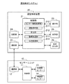
- FIG. 1 is a diagram showing an outline of a motion analysis system according to the first embodiment of the present invention.
- the motion analysis system 1 includes a sensor unit 10 and a motion analysis device 20.
- the sensor unit 10 is an inertial sensor and can measure acceleration generated in each of the three axes and angular velocity generated around each of the three axes, and is attached to the golf club 3.
- the sensor unit 10 is, for example, a part of the shaft portion of the golf club 3 with one of three detection axes (x-axis, y-axis, z-axis), for example, the y-axis aligned with the long axis direction of the shaft portion. Attached to.
- the sensor unit 10 is attached at a position close to a grip portion where a shock during a shot is not easily transmitted and a centrifugal force is not applied during a swing.
- the shaft portion is a portion of the handle excluding the head of the golf club 3 and includes a grip portion.
- User 2 performs a swing motion of hitting a golf ball (not shown) according to a predetermined procedure. For example, the user 2 first holds the golf club 3 and takes an address posture so that the long axis of the shaft portion of the golf club 3 is perpendicular to the target line (for example, the target direction of the hit ball). Still for more than time (for example, more than 1 second). Next, the user 2 performs a swing motion and hits and skips the golf ball.
- the address posture in this specification includes a posture in a stationary state of the user before starting the swing, or a posture in a state where the user swings the exercise equipment (waggles) before starting the swing.
- the sensor unit 10 measures the triaxial acceleration and the triaxial angular velocity at a predetermined cycle (for example, 1 ms), and sequentially transmits the measured data to the motion analysis device 20.
- the sensor unit 10 may transmit the measured data immediately, or store the measured data in the internal memory, and transmit the measured data at a desired timing such as after the end of the swing motion of the user 2. It may be.
- the communication between the sensor unit 10 and the motion analysis device 20 may be wireless communication or wired communication.
- the sensor unit 10 may store the measured data in a removable recording medium such as a memory card, and the motion analysis apparatus 20 may read the measurement data from the recording medium.
- the motion analysis device 20 analyzes the hitting position of the ball in the horizontal direction (left-right direction) of the head of the golf club 3 using the data measured by the sensor unit 10.
- the motion analysis device 20 generates image data including information on the analyzed hitting ball position, and displays an image corresponding to the image data on the display unit.
- the motion analysis device 20 is, for example, a portable device such as a smartphone, a personal computer (PC), or the like. In FIG. 1, the motion analysis device 20 is mounted on the waist of the user 2, but the mounting position is not particularly limited, and the motion analysis device 20 may not be mounted on the user 2.
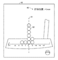
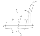
- FIG. 2 is a diagram illustrating the hitting position of the golf club head.
- FIG. 2 shows a part of the shaft portion 3a of the golf club 3 and a hitting ball portion (head) 3b.
- the hitting ball portion 3b has a hitting surface 3c for hitting a ball.
- the golf club 3 is a putter, for example.
- the user 2 indicates a sweet spot in the horizontal direction of the ball striking face 3c of the golf club 3. In general, if the ball can be caught at the sweet spot indicated by the alternate long and short dash line A1, the user 2 can smoothly and smoothly roll the ball.
- FIG. 2 shows the h-axis parallel to the horizontal direction.
- the point where the h-axis and the sweet spot intersect is the origin (0) of the h-axis.
- the right side of the paper surface (the direction of the shaft portion 3a) is negative from the origin of the h axis, and the left side of the paper surface (the direction opposite to the shaft portion 3a) is positive from the origin of the h axis.
- the angular velocity around the major axis of the shaft portion 3a at the time of impact generally increases as the absolute value of the ball hitting position “h” increases.
- the angular velocity around the major axis of the shaft portion 3a generally increases as the ball hitting position moves away from the alternate long and short dash line A1 in the horizontal direction.
- the rotation direction around the major axis of the shaft portion 3a at the time of impact is generally reversed by the positive / negative sign of the ball hitting position “h”.
- the rotation direction around the major axis of the shaft portion 3a is generally the direction opposite to the direction indicated by the arrow A2 (the direction in which the hitting surface 3c opens).
- the motion analysis device 20 can calculate the ball hitting position in the horizontal direction (h-axis direction) of the hitting surface 3c using the angular velocity around the major axis of the shaft portion 3a at the time of impact.
- the direction of the arrow A2 (the direction in which the hitting surface 3c opens) is “positive”.
- FIG. 3 is a block diagram showing an example of the configuration of the motion analysis system.
- the sensor unit 10 includes a control unit 11, a communication unit 12, an acceleration sensor 13, and an angular velocity sensor 14.
- the acceleration sensor 13 measures acceleration generated in each of the three axis directions that intersect (ideally orthogonal) with each other, and outputs a digital signal (acceleration data) corresponding to the magnitude and direction of the measured three axis acceleration. .
- the angular velocity sensor 14 measures an angular velocity generated around each of three axes that intersect each other (ideally orthogonal), and outputs a digital signal (angular velocity data) corresponding to the magnitude and direction of the measured three-axis angular velocity. Output.
- the control unit 11 controls the sensor unit in an integrated manner.
- the control unit 11 receives acceleration data and angular velocity data from the acceleration sensor 13 and the angular velocity sensor 14, respectively, attaches time information, and stores them in a storage unit (not shown).
- the control unit 11 adds time information to the stored measurement data (acceleration data and angular velocity data), generates packet data that matches the communication format, and outputs the packet data to the communication unit 12.
- the acceleration sensor 13 and the angular velocity sensor 14 each have three axes that coincide with the three axes (x axis, y axis, z axis) of the orthogonal coordinate system (sensor coordinate system) defined for the sensor unit 10. Although it is ideal to be attached to the unit 10, an error in the attachment angle actually occurs. Therefore, the control unit 11 performs a process of converting the acceleration data and the angular velocity data into data in the xyz coordinate system using a correction parameter calculated in advance according to the attachment angle error.
- control unit 11 may perform temperature correction processing for the acceleration sensor 13 and the angular velocity sensor 14.
- a temperature correction function may be incorporated in the acceleration sensor 13 and the angular velocity sensor 14.
- the acceleration sensor 13 and the angular velocity sensor 14 may output analog signals.
- the control unit 11 converts the output signal of the acceleration sensor 13 and the output signal of the angular velocity sensor 14 to A / D, respectively.
- Measurement data (acceleration data and angular velocity data) may be generated by (analog / digital) conversion, and packet data for communication may be generated using these.
- the communication unit 12 performs processing for transmitting the packet data received from the control unit 11 to the motion analysis device 20, processing for receiving a control command from the motion analysis device 20 and sending the control command to the control unit 11, and the like.
- the control unit 11 performs various processes according to the control command.
- the motion analysis apparatus 20 includes a control unit 21, a communication unit 22, an operation unit 23, a storage unit 24, a display unit 25, and a voice output unit 26.
- the communication unit 22 performs processing to receive packet data transmitted from the sensor unit 10 and send the packet data to the control unit 21, processing to transmit a control command from the control unit 21 to the sensor unit 10, and the like.
- the operation unit 23 performs a process of acquiring operation data from the user and sending it to the control unit 21.
- the operation unit 23 may be, for example, a touch panel display, a button, a key, a microphone, or the like.
- the storage unit 24 includes, for example, various IC memories such as ROM (Read Only Memory), flash ROM, RAM (Random Access Memory), and recording media such as a hard disk and a memory card.
- ROM Read Only Memory
- flash ROM flash ROM
- RAM Random Access Memory
- recording media such as a hard disk and a memory card.
- the storage unit 24 stores programs for the control unit 21 to perform various calculation processes and control processes, various programs and data for realizing application functions, and the like.
- the storage unit 24 stores a motion analysis program that is read by the control unit 21 and that executes a motion analysis process.
- the motion analysis program may be stored in advance in a nonvolatile recording medium, or the control unit 21 may receive the motion analysis program from the server via the network and store the motion analysis program in the storage unit 24.
- the storage unit 24 stores body information of the user 2, club specification information indicating the specifications of the golf club 3, and sensor mounting position information.
- the user 2 operates the operation unit 23 to input physical information such as height, weight, and sex, and the input physical information is stored in the storage unit 24 as physical information.
- the user 2 inputs the model number of the golf club 3 to be used by operating the operation unit 23 (or selected from the model number list), and the specification information for each model number stored in advance in the storage unit 24 (for example, Of the shaft length, the position of the center of gravity, information on the lie angle, face angle, loft angle, etc.), the specification information of the input model number is used as club specification information.
- the user 2 operates the operation unit 23 to input the distance between the mounting position of the sensor unit 10 and the grip end of the golf club 3, and the information on the input distance is stored as sensor mounting position information.
- the sensor unit 10 may be mounted at a predetermined position (for example, a distance of 20 cm from the grip end), and information on the predetermined position may be stored in advance as sensor mounting position information.
- the storage unit 24 is used as a work area of the control unit 21 and temporarily stores data input from the operation unit 23, calculation results executed by the control unit 21 according to various programs, and the like. Furthermore, the memory
- the display unit 25 displays the processing results of the control unit 21 as characters, graphs, tables, animations, and other images.
- the display unit 25 is, for example, a CRT (Cathode-Ray Tube) display, an LCD (Liquid Crystal Display), an EPD (Electrophoretic Display), a display using an organic light emitting diode (OLED), a touch panel display, an HMD (Head Mounted Display). Etc. In addition, you may make it implement
- the sound output unit 26 outputs the processing result of the control unit 21 as sound such as sound and buzzer sound.
- the audio output unit 26 may be, for example, a speaker or a buzzer.
- the control unit 21 performs processing for transmitting a control command to the sensor unit 10 according to various programs, various calculation processing for data received from the sensor unit 10 via the communication unit 22, and other various control processing.
- the control unit 21 executes a motion analysis program, thereby obtaining a sensor information acquisition unit 210 (corresponding to the acquisition unit of the present invention) and a motion analysis unit 211 (corresponding to the detection unit of the present invention). ), The calculation unit 212, the image generation unit 213, and the output processing unit 214.
- the control unit 21 connects, for example, a CPU (Central Processing Unit) that is an arithmetic device, a RAM (Random Access Memory) that is a volatile storage device, a ROM that is a nonvolatile storage device, and the control unit 21 and other units. It may be realized by a computer including an interface (I / F) circuit to be connected, a bus for connecting these to each other, and the like. The computer may include various dedicated processing circuits such as an image processing circuit.
- the control unit 21 may be realized by ASIC (Application (Specific Integrated Circuit) or the like.
- the sensor information acquisition unit 210 receives packet data received from the sensor unit 10 by the communication unit 22, and acquires time information and measurement data from the received packet data.
- the acquired measurement data includes an angular velocity around the major axis of the shaft portion 3a of the golf club 3 generated by the swing of the user 2. Further, the sensor information acquisition unit 210 stores the acquired time information and measurement data in the storage unit 24 in association with each other.
- the motion analysis unit 211 performs a process of analyzing the swing motion of the user 2 using the measurement data output from the sensor unit 10. Specifically, the motion analysis unit 211 first uses the measurement data (acceleration data and angular velocity data) stored in the storage unit 24 when the user 2 is stationary (at the time of address), and the offset included in the measurement data. Calculate the quantity. Next, the motion analysis unit 211 performs bias correction by subtracting the offset amount from the measurement data after the start of the swing stored in the storage unit 24, and the user 2 is performing the swing operation using the measurement data corrected for bias. The position and orientation of the sensor unit 10 are calculated.
- the motion analysis unit 211 uses the acceleration data measured by the acceleration sensor 13, the club specification information, and the sensor mounting position information, for example, the position of the hitting unit 3b when the user 2 is stationary (at the time of addressing).
- the position of the hitting unit 3b when the user 2 is stationary (at the time of addressing).
- the user 2 is stationary in the coordinate system in which the target direction of the hit ball is the X axis, the horizontal axis perpendicular to the X axis is the Y axis, and the vertical direction is the Z axis (hereinafter also referred to as the global coordinate system).
- the position (initial position) of the sensor unit 10 is calculated, and the subsequent acceleration data is integrated to calculate a change in position from the initial position of the sensor unit 10 in time series.
- the X coordinate of the initial position of the sensor unit 10 is zero. Further, the y-axis of the sensor unit 10 coincides with the long axis direction of the shaft of the golf club 3, and when the user 2 is stationary, the acceleration sensor 13 measures only gravitational acceleration. Can be used to calculate the tilt angle of the shaft (tilt with respect to the horizontal plane (XY plane) or vertical plane (XZ plane)). Then, the motion analysis unit 211 uses the tilt angle of the shaft, club specification information (shaft length), and sensor mounting position information (distance from the grip end) to determine the Y coordinate and Z coordinate of the initial position of the sensor unit 10. And the initial position of the sensor unit 10 can be specified. Alternatively, the motion analysis unit 211 may calculate the coordinates of the initial position of the sensor unit 10 using the coordinates of the position of the grip end of the golf club 3 and the sensor mounting position information (distance from the grip end).
- the motion analysis unit 211 uses the acceleration data measured by the acceleration sensor 13 to calculate the posture (initial posture) of the sensor unit 10 when the user 2 is stationary (addressing) in the XYZ coordinate system (global coordinate system). Then, the rotation calculation using the angular velocity data measured by the angular velocity sensor 14 is performed, and the change in posture of the sensor unit 10 from the initial posture is calculated in time series.
- the attitude of the sensor unit 10 can be expressed by, for example, rotation angles (roll angle, pitch angle, yaw angle) around the X axis, Y axis, and Z axis, Euler angles, and quarter-on (quaternion). .
- the motion analysis unit 211 uses the three-axis acceleration data to determine the x-axis, y-axis, and z-axis of the sensor unit 10 and the direction of gravity. The angle formed by can be specified. Furthermore, since the user 2 stops at a predetermined address posture, the motion analysis unit 211 identifies the initial posture of the sensor unit 10 because the y axis of the sensor unit 10 is on the YZ plane when the user 2 is stationary. be able to.
- the signal processing unit of the sensor unit 10 may calculate the offset amount of the measurement data and perform bias correction of the measurement data, or the bias correction function is incorporated in the acceleration sensor 13 and the angular velocity sensor 14. May be. In these cases, bias correction of measurement data by the motion analysis unit 211 is not necessary.
- the motion analysis unit 211 also includes body information (height of the user 2 (arm length)), club specification information (shaft length and center of gravity position), sensor mounting position information (distance from the grip end), golf club 3) A motion analysis model (double pendulum model, etc.) that takes into account the characteristics of 3 (such as a rigid body) and the characteristics of the human body (such as the direction in which the joint bends) is defined. The trajectory of the golf club 3 in the swing of the user 2 is calculated using the information on the position and orientation of 10.
- the motion analysis unit 211 detects the timing (impact timing) of hitting the ball during the swing motion period of the user 2 using the time information and measurement data stored in the storage unit 24. For example, the motion analysis unit 211 calculates a composite value of measurement data (acceleration data or angular velocity data) output from the sensor unit 10, and specifies the timing (time) when the user 2 hits the ball based on the composite value.
- measurement data acceleration data or angular velocity data
- the motion analysis unit 211 uses the motion analysis model and the position and orientation information of the sensor unit 10, and uses the head speed from back swing to follow-through, the incident angle (club path), the face angle, the shaft at the time of hitting Information such as rotation (a change amount of the face angle during a swing), a deceleration rate of the golf club 3, or information on a variation of each information when the user 2 performs a plurality of swings is also generated.
- the motion analysis unit 211 uses the measurement data acquired from the sensor unit 10 to perform a series of operations (also referred to as “rhythm”) from the start to the end of the swing, for example, from the start of the swing to the back swing, the top, Detects downswing, impact, follow-through, and end of swing.
- a series of operations also referred to as “rhythm”
- the specific rhythm detection procedure is not particularly limited, for example, the following procedure can be adopted.
- the motion analysis unit 211 calculates the sum of the magnitudes of angular velocities around each axis at each time t (referred to as a norm) using the acquired angular velocity data at each time t. Further, the motion analysis unit 211 may differentiate the norm of the angular velocity at each time t with respect to time.
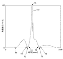
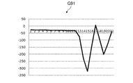
- FIG. 4 an example of an angular velocity output from the sensor unit.
- the horizontal axis represents time (msec) and the vertical axis represents angular velocity (dps).
- the norm of angular velocity appears in a graph as shown in FIG. 5 (a diagram showing an example of the norm of angular velocity), for example.
- the horizontal axis represents time (msec) and the vertical axis represents the norm of angular velocity.
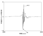
- the differential value of the norm of angular velocity appears in a graph as shown in FIG.
- FIG. 6 (an example of the differential value of the norm of angular velocity), for example.
- the horizontal axis represents time (msec)
- the vertical axis represents the differential value of the norm of angular velocity. 4 to 6 are for easy understanding of the present embodiment, and do not show accurate values.
- the motion analysis unit 211 detects the impact timing in the swing using the calculated norm of the angular velocity. For example, the motion analysis unit 211 detects the timing at which the norm of the angular velocity is maximum as the impact timing (T5 in FIG. 5). Alternatively, for example, the motion analysis unit 211 may detect the previous timing as the impact timing among the timing at which the calculated differential value of the norm of the angular velocity is maximum and minimum (FIG. 6). T5).
- the motion analysis unit 211 detects, for example, the timing at which the calculated norm of the angular velocity is minimized before the impact as the top timing of the swing (T3 in FIG. 5). Further, the motion analysis unit 211 identifies, for example, a continuous period before the impact and the norm of the angular velocity is equal to or less than the first threshold as the top period (the accumulation period at the top) (T2 to T4 in FIG. 5).
- the motion analysis unit 211 detects, for example, the timing at which the norm of the angular velocity is equal to or lower than the second threshold before the top as the timing of the start of the swing (T1 in FIG. 5).
- the motion analysis unit 211 detects, for example, the timing at which the norm of the angular velocity is minimized after the impact as the timing of the end of the swing (T7 in FIG. 5).
- the motion analysis unit 211 may detect the first timing when the norm of the angular velocity is equal to or less than the third threshold after the impact as the timing of the end of the swing (finish).
- the motion analysis unit 211 specifies a continuous period after the impact timing and approaching the impact timing and the norm of the angular velocity is equal to or less than the fourth threshold as the finish period (T6 to T8 in FIG. 5). ).
- the motion analysis unit 211 can detect the rhythm of the swing.
- the motion analysis unit 211 detects each rhythm to detect each period during the swing (for example, a backswing period from the start of the swing to the top start, a downswing period from the top end to the impact, and from the impact to the end of the swing.
- a backswing period from the start of the swing to the top start for example, a backswing period from the start of the swing to the top start, a downswing period from the top end to the impact, and from the impact to the end of the swing.
- follow-through period can be specified.
- the calculation unit 212 is based on the reference line (corresponding to the reference position of the present invention) set on the ball striking surface 3c (reference line) To the hitting ball position).
- the storage unit 24 stores in advance information indicating the relationship between the angular velocity around the major axis of the golf club 3 and the amount of deviation of the hit ball position (hereinafter also referred to as relationship information).
- the calculation unit 212 refers to the relation information stored in the storage unit 24, and calculates the amount of deviation of the hit ball position from the reference line set in the hit ball 3c.
- the angular velocity around the major axis of the shaft portion 3a is acquired by the sensor information acquisition unit 210 as described above. Further, the timing of impact is detected by the motion analysis unit 211 as described above.
- the relational information is, for example, an expression in which the angular velocity around the major axis of the shaft portion 3a is an independent variable, and the amount of deviation of the hit ball position from a reference line (for example, a sweet spot) set on the hitting surface 3c is a dependent variable.
- the calculation unit 212 substitutes the angular velocity around the major axis of the shaft portion 3a at the time of impact acquired by the sensor information acquisition unit 210 into the independent variable of the relationship information, thereby setting the reference line set on the hitting surface 3c. It is possible to calculate the deviation amount (dependent variable) of the hit ball position from
- the related information is acquired in advance, for example, before shipment of the motion analysis system 1 and stored in the storage unit 24.
- an acquirer for example, a manufacturer who manufactures the motion analysis system 1 who acquires the relationship information mounts the sensor unit 10 on the golf club 3, swings the golf club 3, and hits the ball on the hitting surface 3c.
- the relationship information can be acquired.
- the acquirer swings the golf club 3 and hits the ball on the ball striking surface 3c, and measures the angular velocity around the major axis of the shaft portion 3a at the time of impact.
- the acquirer can measure the angular velocity around the major axis of the shaft portion 3a at the time of impact, for example, using the motion analysis device 20.
- the acquirer measures the amount of deviation of the hit ball position from the reference line set for the hit ball 3c when the ball hits the hit ball 3c. For example, the acquirer applies a marker or the like on the ball striking surface 3c of the golf club 3 so that a trace is left when the ball is hit, and the deviation of the ball striking position from the reference line set on the ball striking surface 3c of the golf club 3 Measure the amount.
- the reference line set for the hitting surface 3c is, for example, a sweet spot of the hitting surface 3c.
- the acquirer measures the amount of deviation of the hit ball position from the sweet spot when the ball is hit on the hit ball 3c. Specifically, the acquirer measures the hitting ball position with respect to the origin of the h axis in FIG. Thereby, the calculation part 212 can calculate the deviation
- the reference line may be set to other than the sweet spot.
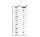
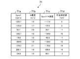
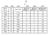
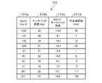
- FIG. 7 is a diagram showing an example of the relationship information.
- the relationship information 31 includes GyroY 31a and hit point measurement values 31b.
- the relationship information 31 is acquired in advance by the acquirer, for example, by the method described above.
- GyroY31a is an angular velocity around the major axis of the shaft portion 3a at the time of impact.
- the hit point measured value 31b is a deviation amount of the hit ball position from the sweet spot in the horizontal direction of the hit ball 3c.
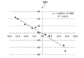
- FIG. 8 is a graph showing an example of the relationship information in FIG.
- the horizontal axis of the graph G1 illustrated in FIG. 8 indicates the angular velocity.
- the vertical axis of the graph G1 indicates the amount of deviation of the hit ball position.
- the black rhombus shown in the graph G1 is obtained by plotting the GyroY 31a and the hit point measurement value 31b of the relationship information 31 in FIG. 7 on the graph G1.
- a correlation is recognized between GyroY 31a and hit point measurement value 31b, and the relationship can be expressed by a linear expression.
- the coefficient and intercept of the linear expression can be obtained by regression analysis.
- the linear expression is expressed by the following expression (1).
- Equation (1) is calculated in advance by the above-described acquirer and stored in the storage unit 24, for example. Accordingly, the calculation unit 212 can calculate the amount of deviation of the hit ball position from the sweet spot when the user 2 swings the golf club 3 by referring to the storage unit 24. For example, the calculation unit 212 calculates the angular velocity around the major axis of the shaft portion 3 a at the time of impact when the user 2 hits the ball with the golf club 3 by “x” in Expression (1) stored in the storage unit 24. By substituting into, the deviation amount “y” from the sweet spot can be calculated.
- the image generation unit 213 performs processing for generating image data including information on the amount of deviation from the sweet spot.
- the output processing unit 214 performs processing for displaying various images (including characters and symbols in addition to images corresponding to the image data generated by the image generation unit 213) on the display unit 25.
- the output processing unit 214 displays an image corresponding to the image data generated by the image generation unit 213 on the display unit 25 automatically after the swing motion of the user 2 ends or according to the input operation of the user 2.
- Display Alternatively, a display unit is provided in the sensor unit 10, and the output processing unit 214 transmits image data to the sensor unit 10 via the communication unit 22 to display various images on the display unit of the sensor unit 10. Also good.
- the output processing unit 214 performs processing for causing the audio output unit 26 to output various sounds (including sound and buzzer sound). For example, the output processing unit 214 reads out various kinds of information stored in the storage unit 24 automatically after a user's 2 swing motion is completed, or when a predetermined input operation is performed. You may make the output part 26 output the sound and sound for motion analysis.
- a sound output unit is provided in the sensor unit 10, and the output processing unit 214 transmits various sound data and sound data to the sensor unit 10 via the communication unit 22, and transmits the sound data to the sound output unit of the sensor unit 10.
- Various sounds and sounds may be output.
- a vibration mechanism may be provided in the motion analysis device 20 or the sensor unit 10, and various information may be converted into vibration information by the vibration mechanism and presented to the user 2.
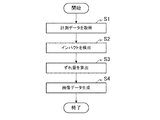
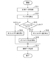
- FIG. 9 is a flowchart showing an example of the operation of the motion analysis apparatus.
- the motion analysis apparatus 20 executes the process of the flowchart of FIG. 9. It is assumed that the relationship information shown in Expression (1) is stored in the storage unit 24 in advance.
- the sensor information acquisition unit 210 acquires measurement data of the sensor unit 10 (step S1).
- the measurement data includes an angular velocity around the major axis of the shaft portion 3a.
- the control part 21 may perform the process after step S2 in real time, if the first measurement data in the swing motion (including a stationary motion) of the user 2 is acquired, or in the swing motion of the user 2 from the sensor unit 10. After acquiring a part or all of the series of measurement data, the processing after step S2 may be performed.
- the motion analysis unit 211 detects the impact timing of the golf club 3 (step S2).
- the calculation unit 212 calculates the length of the shaft portion 3a at the time of impact based on the angular velocity around the major axis of the shaft portion 3a acquired in step S1 and the impact timing detected in step S2. Get the angular velocity around the axis. Then, the calculation unit 212 calculates a deviation amount (distance) of the hit ball position from the sweet spot set on the hit ball 3c based on the acquired angular velocity around the major axis of the shaft portion 3a (step S3). . For example, the calculation unit 212 substitutes the acquired angular velocity around the major axis of the shaft portion 3a into the independent variable of the formula (1) stored in the storage unit 24, and calculates the amount of deviation of the hit ball position. .
- the image generation unit 213 generates image data including information on the shift amount calculated in step S3 (step S4). Thereby, the image data generated by the image generation unit 213 is displayed on the display unit 25 by the output processing unit 214, and the user 2 can grasp the deviation amount of the hit ball position from the sweet spot.
- FIG. 10 is a diagram showing an example of a screen displayed on the display unit.
- the image data generated by the image generation unit 213 is output to the display unit 25 by the output processing unit 214.
- a screen 40 illustrated in FIG. 10 illustrates a screen example displayed on the display unit 25.
- the screen 40 On the screen 40, an image imitating a part of the golf club 3 is displayed.
- the golf club 3 is a putter.
- a one-dot chain line 41 shown on the screen 40 indicates a sweet spot of the golf club 3.
- a circle 42 shown on the screen 40 shows a histogram of the ball hitting positions.
- the diameter of one circle 42 in the horizontal direction indicates the width of the ball hitting position. In the example of the screen 40, the diameter indicates “5 mm”.
- the number of the circles 42 in the vertical direction indicates the frequency of the ball hitting position.
- the frequency of the hit ball position “ ⁇ 5 ⁇ 2.5 (mm)” is “twice”.
- a circle 42 indicated by diagonal lines indicates the latest hit position of the ball.
- the circle 42 indicated by diagonal lines is displayed in the class “0 ⁇ 2.5 (mm)”.
- the hitting position 43 on the screen 40 indicates the latest hitting position of the ball.
- the latest hitting ball position is shifted by “+1 mm” from the sweet spot.
- the sensor information acquisition unit 210 of the motion analysis apparatus 20 acquires the angular velocity around the major axis of the shaft portion 3a of the golf club 3 generated by the swing.
- the motion analysis unit 211 detects the impact timing of the golf club 3.
- the calculation unit 212 calculates the amount of deviation of the hit ball position from the reference line set on the hit ball 3c of the golf club 3 based on the angular velocity at the time of impact.
- the user 2 can grasp the deviation of the hit ball position from the reference line set on the hit ball 3c of the golf club 3.
- the swing technique can be improved.
- the image generation unit 213 generates image data that displays the hit position of the ball as a histogram. Thereby, the user 2 can easily grasp where the ball has hit the ball hitting surface 3c of the golf club 3 in the past and the latest swing.
- the storage unit 24 stores the relationship information represented by the linear expression in advance.
- the acquirer may store the relationship information 31 illustrated in FIG.
- the calculation unit 212 may acquire an amount near the angular velocity acquired by the sensor information acquisition unit 210 from the storage unit 24, perform a complement process, and calculate the amount of deviation of the hit ball position.
- the related information is stored in the storage unit 24 before shipment of the motion analysis system 1, but is not limited thereto.
- the motion analysis apparatus 20 may download related information from a site such as a manufacturer after shipment and store the related information in the storage unit 24.
- the acceleration sensor 13 and the angular velocity sensor 14 are integrated in the sensor unit 10, but the acceleration sensor 13 and the angular velocity sensor 14 may not be integrated. Alternatively, the acceleration sensor 13 and the angular velocity sensor 14 may be directly attached to the golf club 3 or the user 2 without being built in the sensor unit 10. In the above description, the sensor unit 10 and the motion analysis device 20 are separate, but they may be integrated so as to be mounted on the golf club 3 or the user 2.
- the sensor unit 10 may have a light emitting unit such as an LED. Then, the output processing unit 214 may output the calculation result of the calculation unit 212 to the light emitting unit. For example, the output processing unit 214 emits the first color such as green from the light emitting unit when the deviation amount of the hit ball position is within a predetermined range from the sweet spot (for example, ⁇ 2.5 (mm)). To. Further, the output processing unit 214 emits a second color such as red from the light emitting unit when the deviation amount of the hit ball position is larger than a predetermined range from the sweet spot (for example, larger than +2.5 (mm)). To. Further, the output processing unit 214 emits the third color such as blue from the light emitting unit when the deviation amount of the hit ball position is smaller than a predetermined range from the sweet spot (for example, smaller than ⁇ 2.5 (mm)). Like that.
- the first color such as green from the light emitting unit when the deviation amount of the hit ball position is within a predetermined range from the sweet spot (for example
- the sensor unit 10 may have an audio output unit such as a speaker. Then, the output processing unit 214 may output the calculation result of the calculation unit 212 by voice from the voice output unit.
- the storage unit 24 has relationship information indicating the relationship between the information (value) obtained by dividing the angular velocity of the shaft portion 3a by the speed of the hitting ball portion 3b and the amount of deviation of the hitting ball position.
- the calculation unit 212 divides the angular velocity at the time of impact acquired by the sensor information acquisition unit 210 by the speed of the hit ball portion 3b at the time of impact, and refers to the storage unit 24 based on the value obtained by the division.
- the amount of deviation of the hit ball position is calculated. Below, a different part from 1st Embodiment is demonstrated.
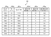
- FIG. 11 is a diagram illustrating an example of relation information according to the second embodiment.
- the relationship information 51 includes GyroY 51a, HS (head speed) 51b, GyroY / HS 51c, and hit point measurement value 51d.
- GyroY51a is an angular velocity around the major axis of the shaft portion 3a at the time of impact. GyroY 51a is acquired in advance by the acquirer, for example, in the same manner as in the first embodiment.
- HS51b is the speed of the hit ball portion 3b at the time of impact.
- HS51b is acquired in advance by the acquirer in the same manner as GyroY51a.
- the acquirer can acquire the HS 51b using the motion analysis apparatus 20, for example.
- the motion analysis unit 211 calculates the head speed from the back swing to the follow-through using the motion analysis model and the position and orientation information of the sensor unit 10. be able to. That is, the motion analysis unit 211 can calculate the speed of the hit ball portion 3b at the time of impact.
- GyroY / HS51c is a value obtained by dividing GyroY51a by HS51b.
- the hit point measured value 51d is a deviation amount of the hit ball position from the sweet spot in the horizontal direction of the hit ball 3c.
- the hit point measurement value 51d is acquired in advance by the acquirer using a marker or the like in the same manner as in the first embodiment.
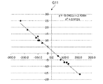
- FIG. 12 is a graph showing an example of the relationship information in FIG.
- the horizontal axis of the graph G11 illustrated in FIG. 12 indicates a value obtained by dividing the angular velocity by the head speed.
- the vertical axis of the graph G11 indicates the amount of deviation of the hit ball position.
- the black rhombus shown in the graph G11 is obtained by plotting the GyroY / HS 51c and the hit point measurement value 51d of the relationship information 51 in FIG. 11 on the graph G11.
- the GyroY / HS 51c and the hit point measurement value 51d have a correlation, and the relationship can be expressed by a linear expression.
- the coefficient and intercept of the linear expression can be obtained by regression analysis.
- the linear expression is expressed by the following expression (2).
- Equation (2) is calculated in advance by the acquirer and stored in the storage unit 24 as in the first embodiment. Accordingly, the calculation unit 212 can calculate the amount of deviation of the hit ball position from the sweet spot when the user 2 swings the golf club 3 by referring to the storage unit 24.
- the calculation unit 212 divides the angular velocity around the major axis of the shaft portion 3a at the time of impact when the user 2 hits the ball with the golf club 3 by the speed of the hitting portion 3b at the time of impact. Then, the calculation unit 212 can calculate the amount of deviation from the sweet spot by substituting the value obtained by dividing the angular velocity by the speed into “x” in Expression (2) stored in the storage unit 24. Note that the speed of the hit ball portion 3b at the time of impact is calculated by the motion analysis unit 211 as described in the first embodiment.
- the calculation unit 212 can calculate a more accurate shift amount by calculating the shift amount of the hit ball position using the relationship information represented by Expression (2).
- the correlation between GyroY / HS 51c and the hit point measured value 51d is stronger than the correlation between GyroY 31a and the hit point measured value 31b.
- the angular velocity around the major axis of the shaft portion 3a and the speed of the hit ball portion 3b at the time of impact are proportional. This is because it is considered to be.
- the relationship information indicates the relationship between the value obtained by dividing the angular velocity around the major axis of the shaft portion 3a by the speed of the hitting ball portion 3b and the deviation amount of the hitting ball position.
- the calculation part 212 divides the angular velocity around the major axis of the shaft part 3a at the time of impact by the speed of the hit ball part 3b at the time of impact, and refers to the related information based on the value obtained by the division, The amount of deviation of the hit ball position is calculated.
- the motion analysis apparatus 20 can calculate the shift amount of the hit ball position more accurately.
- the user 2 can more accurately grasp the deviation of the hit ball position from the reference line set on the hit ball 3c of the golf club 3.
- the motion analysis unit 211 may calculate the speed of the hit ball portion 3b at the time of impact using a general method other than the above. For example, the motion analysis unit 211 may obtain the angular velocity of the swing axis perpendicular to the swing plane of the shaft portion 3a and the distance between the swing axis and the hitting ball portion 3b.
- the relationship information generally varies depending on the type of golf club 3 (corresponding to the shape of the present invention).
- the putter includes a pin type, a mallet type, a neo mallet type, and the like, and the relationship information differs depending on each type.
- the relationship information according to the type of the golf club 3 is stored in the storage unit 24, and the golf club 3 used by the user 2 also calculates the shift amount of the hit ball position according to the type. Is switched. Below, a different part from 1st Embodiment and 2nd Embodiment is demonstrated.
- FIG. 13 is a diagram showing an example of relation information according to the third embodiment.
- the relationship information 61 shown in FIG. 13 indicates the relationship information when the golf club 3 is a neo-mallet type.
- the relationship information 61 includes GyroY 61a, HS61b, GyroY / HS61c, and a hit point measurement value 61d.
- GyroY61a, HS61b, GyroY / HS61c, and hitting point measurement value 61d are the same as GyroY51a, HS51b, GyroY / HS51c, and hitting point measurement value 51d in FIG.
- GyroY51a, HS51b, GyroY / HS51c, and hit point measured value 51d of FIG. 11 have shown the related information in case the golf club 3 is a pin type.
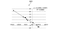
- FIG. 14 is a graph showing an example of the relationship information of FIG.
- the horizontal axis of the graph G21 shown in FIG. 14 indicates a value obtained by dividing the angular velocity by the head speed.
- the vertical axis of the graph G21 indicates the amount of deviation of the hit ball position.
- the black rhombus shown in the graph G21 is obtained by plotting the GyroY / HS 61c and the hit point measurement value 61d of the relationship information 61 in FIG. 13 on the graph G21.
- the GyroY / HS 61c and the hit point measurement value 61d of the neo-mallet type golf club 3 have a correlation, and the relationship can be expressed by a linear expression.
- the coefficient and intercept of the linear expression can be obtained by regression analysis.
- the linear expression is expressed by the following expression (3).
- Equation (3) is stored in advance in the storage unit 24 as in the above embodiments.
- the calculation part 212 can calculate the amount of deviation of the hit ball position from the sweet spot when the user 2 swings the neo-mallet type golf club 3 by referring to the storage part 24.
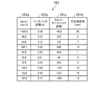
- FIG. 15 is a diagram showing an example of other types of relationship information.
- Relation information 71 shown in FIG. 15 indicates relation information when the golf club 3 is of the mallet type.
- the relationship information 71 includes GyroY 71a, HS 71b, GyroY / HS 71c, and hit point measurement value 71d.
- GyroY71a, HS71b, GyroY / HS71c, and hit point measured value 71d are the same as GyroY61a, HS61b, GyroY / HS61c, and hit point measured value 61d in FIG.
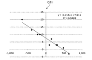
- FIG. 16 is a graph showing an example of the relationship information in FIG.
- the horizontal axis of the graph G31 illustrated in FIG. 16 indicates a value obtained by dividing the angular velocity by the head speed.
- the vertical axis of the graph G31 indicates the amount of deviation of the hit ball position.
- the black rhombus shown in the graph G31 is obtained by plotting the GyroY / HS 71c and the hit point measurement value 71d of the relationship information 71 in FIG. 15 on the graph G31.
- the GyroY / HS 71c of the mallet type golf club 3 and the hit point measured value 71d have a correlation, and the relationship can be expressed by a linear expression.
- the coefficient and intercept of the linear expression can be obtained by regression analysis.
- the linear expression is expressed by the following expression (4).
- Equation (4) is stored in advance in the storage unit 24 as in the above embodiments. Thereby, the calculation unit 212 can calculate the amount of deviation of the hit ball position from the sweet spot when the user 2 swings the mallet type golf club 3 by referring to the storage unit 24.
- FIG. 17 is a flowchart showing an example of the operation of the motion analysis apparatus.
- the motion analysis device 20 executes the process of the flowchart of FIG. 17.
- the storage unit 24 stores in advance the relationship information shown in Expression (2), Expression (3), and Expression (4).
- the operation unit 23 receives the type of the golf club 3 used by the user 2 from the user 2.
- the operation unit 23 stores the type of the golf club 3 received from the user 2 in the storage unit 24, for example.
- the sensor information acquisition unit 210 acquires measurement data of the sensor unit 10 (step S11).
- the measurement data includes the angular velocity around the major axis of the shaft portion 3a and the head speed from the back swing to the follow-through (speed of the hitting ball portion 3b).
- the control part 21 may perform the process after step S12 in real time, if the first measurement data in the swing motion (including a stationary motion) of the user 2 is acquired, or in the swing motion of the user 2 from the sensor unit 10. After acquiring a part or all of a series of measurement data, the process after step S12 may be performed.
- the motion analysis unit 211 detects the impact timing of the golf club 3 (step S12).
- the calculation unit 212 refers to the storage unit 24 to determine whether the type of the golf club 3 of the user 2 is a neo-mallet type, a mallet type, or a pin type (step S13). .
- the calculation unit 212 determines that the type of the golf club 3 of the user 2 is a neo-mallet type (“neo-mallet type” in S13)
- the calculation unit 212 proceeds to step S14.
- the calculation unit 212 determines that the type of the golf club 3 of the user 2 is the mallet type (“Mallet type” in S13)
- the calculation unit 212 proceeds to step S15.
- the calculation unit 212 determines that the type of the golf club 3 of the user 2 is a pin type (“pin type” in S13)
- the calculation unit 212 proceeds to step S16.
- step S13 If the calculation unit 212 determines in step S13 that the type of the golf club 3 is the “neomalet type”, the calculation unit 212 uses the formula (3) stored in the storage unit 24 to calculate the sweet spot at the hitting position. Is calculated (step S14).
- the calculation unit 212 rotates around the long axis of the shaft portion 3a at the time of impact. Get the angular velocity of. Further, the calculation unit 212 acquires the head speed at the time of impact based on the head speed acquired in step S11 and the impact timing detected in step S12. Then, the calculation unit 212 divides the angular velocity at the time of impact by the head speed at the time of impact, and substitutes the value obtained by the division into the independent variable of the formula (3), so that the deviation of the hit ball position from the sweet spot Calculate the amount. When the calculation unit 212 calculates the deviation amount of the hit ball position, the process proceeds to step S17.
- step S13 If the calculation unit 212 determines in step S13 that the type of the golf club 3 is the “mallet type”, the calculation unit 212 uses the formula (4) stored in the storage unit 24 to calculate from the sweet spot at the hit ball position. A deviation amount is calculated (step S15).
- the calculation unit 212 rotates around the long axis of the shaft portion 3a at the time of impact. Get the angular velocity of. Further, the calculation unit 212 acquires the head speed at the time of impact based on the head speed acquired in step S11 and the impact timing detected in step S12. Then, the calculation unit 212 divides the angular velocity at the time of impact by the head speed at the time of impact, and substitutes the value obtained by the division into the independent variable of the equation (4), so that the deviation of the hit ball position from the sweet spot Calculate the amount. When the calculation unit 212 calculates the deviation amount of the hit ball position, the process proceeds to step S17.
- step S13 If the calculation unit 212 determines in step S13 that the type of the golf club 3 is “pin type”, the calculation unit 212 uses the formula (2) stored in the storage unit 24 to calculate the position from the sweet spot at the hitting position. A deviation amount is calculated (step S16).
- the calculation unit 212 rotates around the long axis of the shaft portion 3a at the time of impact. Get the angular velocity of. Further, the calculation unit 212 acquires the head speed at the time of impact based on the head speed acquired in step S11 and the impact timing detected in step S12. Then, the calculation unit 212 divides the angular velocity at the time of impact by the head speed at the time of impact, and substitutes the value obtained by the division into the independent variable of the equation (4), so that the deviation of the hit ball position from the sweet spot Calculate the amount. When the calculation unit 212 calculates the deviation amount of the hit ball position, the process proceeds to step S17.
- the image generation unit 213 generates image data including information on the shift amount calculated in step S14, step S15, or step S16 (step S17). Thereby, the image data generated by the image generation unit 213 is displayed on the display unit 25 by the output processing unit 214, and the user 2 grasps the amount of deviation of the hit ball position according to the golf club 3 being used. Can do.
- the relationship information is acquired in advance according to the type of the golf club 3 and stored in the storage unit 24. Then, the calculation unit 212 calculates the hit amount of the hit ball position using the relationship information corresponding to the type of the golf club 3 used by the user 2.
- the calculation unit 212 can calculate a more accurate amount of displacement of the hit ball position according to the type of the golf club 3.
- the relationship information of the three types of neo-mallet type, mallet type, and pin type is stored in advance in the storage unit 24, and the calculation unit 212 calculates the amount of displacement of the hit ball position according to each type.
- the calculation unit 212 calculates the amount of displacement of the hit ball position according to each type.
- two types of relationship information or four types or more of relationship information may be stored in the storage unit 24 in advance, and the amount of deviation of the hit ball position corresponding to each type may be calculated.
- the storage unit 24 may store related information of the golf club 3 according to the manufacturer, model number, etc. of the golf club 3. Then, the calculation unit 212 may receive the manufacturer, model number, and the like of the golf club 3 to be used from the user 2 and calculate the amount of deviation of the hit ball position according to the golf club 3.
- the angular velocity around the major axis of the shaft portion 3a is divided by the speed of the hitting ball portion 3b, but it is not necessary to divide by the speed of the hitting ball portion 3b.
- the correlation between the angular velocity around the major axis of the shaft portion 3a and the amount of deviation of the hit ball position may be calculated to calculate the amount of deviation of the hit ball position.
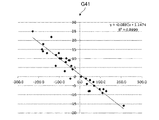
- FIG. 18 is a graph showing an example of relation information according to the fourth embodiment.
- the horizontal axis of the graph G41 illustrated in FIG. 18 indicates a value obtained by dividing the angular velocity by the head speed.
- the vertical axis of the graph G41 indicates the amount of deviation of the hit ball position.
- the black rhombus shown in the graph G41 shows the GyroY / HS 51c and hit point measurement value 51d in FIG. 11, the Gyro Y / HS 61c and hit point measurement value 61d in FIG. 13, and the Gyro Y / HS 71c and hit point measurement value 71d in FIG. Plotted on G41. That is, the black rhombus shown in the graph G41 is obtained by plotting the pin type, neomaret type, and mallet type GyroY / HS and the hit point measurement values on the graph G41.
- the pin type, neo-mallet type, and mallet type GyroY / HS and the hit point measurement value have a correlation, and the relationship can be expressed by a linear expression.
- the coefficient and intercept of the linear expression can be obtained by regression analysis.
- the linear expression is expressed by the following expression (5).
- Equation (5) is stored in advance in the storage unit 24 as in the above embodiments.
- the calculation unit 212 refers to the storage unit 24 to calculate the amount of deviation of the hit ball position even if the user 2 uses the golf club 3 of any of the pin type, neo-mallet type, and mallet type. can do.
- the relationship information indicates the relationship between the angular velocity and the shift amount in various types of the golf club 3.
- the calculation unit 212 can calculate an appropriate amount of deviation of the hit ball position even if the user 2 uses various types of golf clubs 3.
- the horizontal hit point measurement value measured by the acquirer is corrected by the vertical hit point measurement value and the golf club 3 lie angle.
- FIG. 19 is a diagram for explaining correction of the hit value measured in the horizontal direction according to the fifth embodiment. 19, the same components as those in FIG. 2 are denoted by the same reference numerals, and the description thereof is omitted.
- FIG. 19 shows the long axis A11 of the shaft portion 3a.
- the reference line set on the hitting surface 3c may not be set vertically as indicated by the alternate long and short dash line A1.
- the alternate long and short dash line A1 For example, as indicated by a one-dot chain line A12, it may be set to be parallel to the long axis A11. That is, the reference line set for the hitting surface 3c may be set to have the same angle as the lie angle.
- the distance from the reference line of the ball hitting position in the horizontal direction is the height of the ball hitting position and the golf club 3 line. It depends on the corner. For example, even if the hitting position in the horizontal direction is the same, the distance from the reference line (dashed line A12) of the hitting position is different if the height of the hitting position is different. Therefore, in the fifth embodiment, the hitting point measurement value in the horizontal direction is corrected by the hitting point measurement value in the vertical direction and the lie angle of the golf club 3.
- the formula for correcting the hit point measurement value in the horizontal direction of the hitting surface 3c is shown by the following formula (6).
- Hm H + V / tan ⁇ (6)
- “Hm” is the measured value of the hitting point in the horizontal direction after correction.
- “H” is a dot measurement value in the horizontal direction before correction. That is, “H” is a measured value in the horizontal direction obtained by the acquirer using a marker or the like, and is a distance from the origin determined by the acquirer (for example, “0” on the h axis in FIG. 19). is there.
- “V” is a measured value of the hitting point in the vertical direction, and is the height of the hitting ball portion 3b from the sole. The hit point measurement value “V” in the vertical direction is acquired by the acquirer with a marker or the like in the same manner as the hit point measurement value “H” in the horizontal direction.
- “ ⁇ ” is the lie angle (rad) of the golf club 3.
- the measured value of hitting points in the horizontal direction is corrected so as to increase as the measured value of hitting points in the vertical direction increases (that is, as “V” in the second term on the right side of equation (6) increases). , “Hm” increases). Further, as the lie angle “ ⁇ ” of the golf club 3 is larger (as the long axis of the shaft portion 3a is closer to the vertical), the influence of the measured value of the hitting point in the vertical direction on the correction of the measured value of the hitting point in the horizontal direction is smaller. (That is, the second term on the right side of equation (6) becomes smaller).
- FIG. 20 is a diagram showing an example of the relationship information.
- the relationship information 81 includes GyroY 81a, HS 81b, GyroY / HS 81c, left and right hit point measurement value 81d, height hit point measurement value 81e, and height correction left and right hit point position 81f. ing.
- GyroY81a, HS81b, GyroY / HS81c, and left and right hit point measurement values 81d are the same as GyroY51a, HS51b, GyroY / HS51c, and hit point measurement value 51d described in FIG.
- the height hit point measured value 81e is a hitting position in the vertical direction of the hitting surface 3c.
- the height hit point measurement value 81e indicates the height of the hit ball portion 3b from the sole.
- the height hit point measurement value 81e is acquired in advance by the acquirer using a marker or the like in the same manner as the left and right hit point measurement value 81d.
- the height-corrected left / right dot position 81f is a value obtained by correcting the left / right dot measured value 81d by the above equation (6).
- the lie angle of the golf club 3 is set to “70 degrees” (1.22 rad), and the height-corrected left / right spot position 81f is calculated.
- FIG. 21 is a graph showing an example of the relationship information of FIG.
- the horizontal axis of the graph G51 illustrated in FIG. 21 indicates a value obtained by dividing the angular velocity by the head speed.
- the vertical axis of the graph G51 indicates the amount of deviation of the hit ball position.
- the black rhombus shown in the graph G51 is obtained by plotting the GyroY / HS 81c and the height-corrected left / right dot position 81f of the relationship information 81 in FIG. 20 on the graph G51.
- Equation (7) is stored in advance in the storage unit 24 as in the above embodiments. Thereby, the calculation unit 212 can calculate the amount of deviation of the hit ball position from the sweet spot by referring to the storage unit 24.
- the hitting value measured in the horizontal direction of the related information is corrected by the hitting value measured in the vertical direction and the lie angle of the shaft portion 3a.
- the calculation unit 212 can calculate an appropriate amount of deviation of the hit ball position.
- the storage unit 24 may store related information corrected at various lie angles. Then, the calculation unit 212 may calculate the shift amount with reference to the relationship information according to the lie angle of the golf club 3 used by the user 2. Thereby, the calculation unit 212 can calculate a more appropriate amount of displacement of the hit ball position.
- the hit point measurement value in the horizontal direction may be corrected by adding a predetermined angle to the lie angle so that the contribution rate is improved.
- FIG. 22 is a diagram showing an example of relation information when a predetermined angle is added to the lie angle.
- the same components as those in FIG. 20 are denoted by the same reference numerals.
- the relationship information 91 differs from the relationship information 81 of FIG.
- the height-corrected left / right dot position 91a is a value obtained by correcting the left / right dot measured value 81d by the above equation (6).
- “ ⁇ 20 degrees” is added to the lie angle “70 degrees” of the golf club 3 to calculate the height-corrected left / right spot position 91a. That is, the height correction left / right dot position 91a is calculated by setting “ ⁇ ” in Expression (6) to “50 degrees” (0.87 rad).
- FIG. 23 is a graph showing an example of the relationship information of FIG.
- the horizontal axis of the graph G61 shown in FIG. 23 indicates a value obtained by dividing the angular velocity by the head speed.
- the vertical axis of the graph G61 indicates the amount of deviation of the hit ball position.
- the black rhombus shown in the graph G61 is obtained by plotting the GyroY / HS 81c and the height-corrected left / right dot position 91a of the relationship information 91 in FIG. 22 on the graph G61.
- a predetermined angle may be added to the lie angle to correct the measured value of the hitting point in the horizontal direction.
- the calculation unit 212 can calculate an appropriate amount of deviation of the hit ball position.
- the relational information is the relationship between the value obtained by dividing the angular velocity of the shaft portion 3a by the takeback distance and the amount of deviation of the hit ball position.
- FIG. 24 is a diagram showing an example of relation information according to the sixth embodiment.
- the relationship information 101 includes GyroY 101a, takeback distance 101b, GyroY / takeback distance 101c, and hit point measurement value 101d.
- the GyroY 101a and the hit point measurement value 101d are the same as the GyroY 51a and the hit point measurement value 51d described with reference to FIG.
- the takeback distance 101b is a distance from the address of the hitting ball portion 3b to the top.
- the takeback distance 101b is acquired in advance by the acquirer using the motion analysis apparatus 20, for example.
- the motion analysis unit 211 can calculate the takeback distance using the motion analysis model and information on the position and orientation of the sensor unit 10.
- GyroY / takeback distance 101c is a value obtained by dividing GyroY101a by takeback distance 101b.
- FIG. 25 is a graph showing an example of the relationship information of FIG.
- the horizontal axis of the graph G71 illustrated in FIG. 25 indicates a value obtained by dividing the angular velocity by the takeback distance.
- the vertical axis of the graph G71 indicates the amount of deviation of the hit ball position.
- the black rhombus shown in the graph G71 is obtained by plotting the GyroY / takeback distance 101c and the hit point measurement value 101d of the relationship information 101 in FIG. 24 on the graph G71.
- Equation (9) is stored in advance in the storage unit 24 as in the above embodiments. Thereby, the calculation unit 212 can calculate the amount of deviation of the hit ball position from the sweet spot by referring to the storage unit 24.
- the takeback distance and the speed of the hit ball portion 3b at the time of impact have a proportional relationship.
- the greater the takeback distance the greater the speed of the hit ball portion 3b at the time of impact.
- the relationship information according to the sixth embodiment is considered to have a stronger correlation than the relationship information according to the first embodiment, as in the second embodiment.
- the relationship information indicates the relationship between the value obtained by dividing the angular velocity around the major axis of the shaft portion 3a by the takeback distance of the hitting ball portion 3b and the amount of deviation of the hitting ball position. Then, the calculation unit 212 divides the angular velocity around the major axis of the shaft portion 3a at the time of impact by the takeback distance of the hitting ball portion 3b, refers to the relationship information based on the value obtained by the division, and determines the hitting ball position The amount of deviation is calculated.
- the motion analysis apparatus 20 can calculate the shift amount of the hit ball position more accurately.
- the relationship between the value obtained by dividing the angular velocity of the shaft portion 3a by the takeback distance of the hitting ball portion 3b and the amount of deviation of the hitting ball position is used as the related information.
- the relationship between the value obtained by dividing the angular velocity of the shaft portion 3a by the takeback angle and the amount of deviation of the hit ball position is used as the related information.
- FIG. 26 is a diagram showing an example of relation information according to the seventh embodiment.
- the relationship information 111 includes GyroY 111a, a takeback angle 111b, a GyroY / takeback angle 111c, and a hit point measurement value 111d.
- the GyroY 111a and the hit point measured value 111d are the same as the GyroY 51a and the hit point measured value 51d described with reference to FIG.
- the takeback angle 111b is an angle formed by the hitting ball portion 3b at the address and the hitting ball portion 3b at the top.
- the takeback angle 111b is acquired in advance by the acquirer using the motion analysis apparatus 20, for example.
- the motion analysis unit 211 can calculate the takeback angle using the motion analysis model and information on the position and orientation of the sensor unit 10.
- GyroY / takeback angle 111c is a value obtained by dividing GyroY111a by takeback angle 111b.
- FIG. 27 is a graph showing an example of the relationship information of FIG.
- the horizontal axis of the graph G81 illustrated in FIG. 27 indicates a value obtained by dividing the angular velocity by the takeback angle.
- the vertical axis of the graph G81 indicates the amount of deviation of the hit ball position.
- the black rhombus shown in the graph G81 is obtained by plotting the GyroY / takeback angle 111c and the hit point measurement value 111d of the relationship information 111 in FIG. 26 on the graph G81.
- a correlation is recognized between the GyroY / takeback angle 111c and the hit point measurement value 111d, and the relationship can be expressed by a linear expression.
- the coefficient and intercept of the linear expression can be obtained by regression analysis.
- the linear expression is expressed by the following expression (10).
- Equation (10) is stored in advance in the storage unit 24 as in the above embodiments. Thereby, the calculation unit 212 can calculate the amount of deviation of the hit ball position from the sweet spot by referring to the storage unit 24.
- the takeback angle and the speed of the hit ball portion 3b at the time of impact have a proportional relationship.
- the larger the takeback angle the higher the speed of the hit ball portion 3b at the time of impact.
- the relationship information according to the seventh embodiment is considered to have a stronger correlation than the relationship information of the first embodiment, as in the second embodiment.
- the relationship information indicates the relationship between the value obtained by dividing the angular velocity around the major axis of the shaft portion 3a by the takeback angle of the hitting ball portion 3b and the amount of deviation of the hitting ball position. Then, the calculation unit 212 divides the angular velocity around the major axis of the shaft portion 3a at the time of impact by the takeback angle of the hitting ball portion 3b, and refers to the relationship information based on the value obtained by the division, and determines the hitting ball position The amount of deviation is calculated.
- the motion analysis apparatus 20 can calculate the shift amount of the hit ball position more accurately.
- an eighth embodiment will be described with reference to the drawings.
- an average value of angular velocities before impact is calculated, and the calculated average value of angular velocities is subtracted from the angular speed at impact to obtain the angular velocity at impact.
- FIG. 28 is a diagram for explaining the angular velocity calculation according to the eighth embodiment.
- the horizontal axis of the graph G91 shown in FIG. 28 shows the sample point of angular velocity.
- the vertical axis of the graph G91 indicates the angular velocity.
- the waveform shown in the graph G91 indicates the angular velocity around the major axis of the shaft portion 3a acquired by the sensor information acquisition unit 210.
- the time when the absolute value is the largest is the time of impact.
- the sample point “15” is the time of impact.
- the calculation unit 212 calculates an average value of a predetermined number of angular velocities before impact. Then, the calculation unit 212 subtracts the calculated average value of the angular velocities from the angular velocity at the time of impact.
- the predetermined number before impact is “10”, for example.
- the sample point immediately before the impact may be used as the starting point, or a sample point that is a predetermined number of times after the impact may be used as the starting point.
- the calculation unit 212 calculates the average value of the angular velocities of the 10 samples of the sample points “5, 6,. . Then, the calculation unit 212 subtracts the calculated average value of the angular velocities of the 10 samples from the angular velocity of the sample point “15” at the time of impact, and sets the value obtained by the subtraction as the angular velocity at the time of impact.
- the calculation unit 212 calculates the average value of the angular velocities of the 10 samples of the sample points “3, 4,. calculate.
- the calculation unit 212 may subtract the calculated average value of the angular velocities of the 10 samples from the angular velocity of the sample point “15” at the time of impact, and use the value obtained by the subtraction as the angular velocity at the time of impact.
- the offset of the sensor unit 10 is subtracted from the angular velocity at the time of impact. That is, the calculation unit 212 calculates the angular velocity around the major axis of the shaft portion 3a, which is generated by hitting the ball, by the above calculation.
- the calculation unit 212 calculates an average value of a predetermined number of angular velocities before impact, subtracts the calculated average value of angular velocities from the angular velocity at the time of impact, and uses the subtracted value to determine the amount of deviation of the hit ball position. Is calculated.
- the motion analysis apparatus 20 can calculate the shift amount of the hit ball position more accurately.
- a putter has been described as an example of the golf club 3, but the present invention is not limited thereto.
- it can be applied to clubs such as drivers and irons.
- a motion analysis system that analyzes a golf swing
- motion analysis device that analyzes a golf swing
- the present invention is a motion analysis system that analyzes swings of various motions such as tennis and baseball. It can be applied to (motion analysis device).
- the above embodiments can be combined.
- the third embodiment may be combined with any one of the fifth embodiment, the sixth embodiment, or the seventh embodiment.
- the functional configuration of the motion analysis system described above is classified according to the main processing contents in order to facilitate understanding of the configuration of the motion analysis system.
- the present invention is not limited by the way of classification and names of the constituent elements.
- the configuration of the motion analysis system can be classified into more components depending on the processing content. Moreover, it can also classify
- each processing unit in the above flow diagram is divided according to the main processing contents in order to facilitate understanding of the processing of the motion analysis system.
- the present invention is not limited by the way of dividing the processing unit or the name.
- the processing of the motion analysis system can be divided into more processing units according to the processing content. Moreover, it can also divide
- the technical scope of this invention is not limited to the range as described in the said embodiment. It will be apparent to those skilled in the art that various changes and modifications can be made to the above-described embodiment. Further, it is apparent from the scope of the claims that embodiments with such changes or improvements can also be included in the technical scope of the present invention.
- the present invention can also be provided as a motion analysis method, a program for a motion analysis device, and a storage medium storing the program.
- the sensor unit 10 and the motion analysis device 20 are described as separate bodies. However, the function of the motion analysis device 20 may be mounted on the sensor unit 10.
- Motion analysis system 1 Motion analysis system 1 2: User 3: Golf club 3a: Shaft portion 3b: Hitting ball portion 3c: Hitting ball 10: Sensor unit 20: Motion analysis device 21: Control unit 210: Sensor information acquisition unit 211: Motion analysis unit 212 : Calculation unit 213: image generation unit 214: output processing unit 22: communication unit 23: operation unit 24: storage unit 25: display unit 26: audio output unit 31: related information 40: screen.
Abstract
A user cannot perceive how far offset a batted ball is from a reference position set on a ball hitting surface of an exercise apparatus. A sensor information acquiring unit 210 acquires an angular speed about the axis of a shaft part of an exercise apparatus from a sensor unit 10. An exercise analysis unit 211 detects the impact timing of the exercise apparatus. A calculation unit 212 calculates the distance to a ball hitting position from the reference position set on the ball hitting surface of the exercise apparatus on the basis of the angular speed at the time of impact.
Description
本発明は、運動解析装置、運動解析方法、プログラム、記録媒体、及び運動解析システムに関する。
The present invention relates to a motion analysis device, a motion analysis method, a program, a recording medium, and a motion analysis system.
特許文献1には、運動器具のシャフト軸回りの回転を計測し、回転量に基づき、打球がスイートスポットに入ったかどうか判定することが記載されている。特許文献1では、ユーザーは、打球がスイートスポットに入ったか否か把握することができる。
Patent Document 1 describes that the rotation of the exercise apparatus around the shaft axis is measured and it is determined whether or not the hit ball has entered the sweet spot based on the rotation amount. In Patent Document 1, a user can grasp whether or not a hit ball has entered a sweet spot.
しかしながら、ユーザーは、打球がスイートスポットからどのくらい外れているかを具体的に示すことまでは記載されていない。
However, it is not described until the user specifically indicates how far the hit ball is off the sweet spot.
そこで本発明は、打球が運動器具の打球面に設定された基準位置からどのくらいずれているか把握することができる技術を提供することを目的とする。
Therefore, an object of the present invention is to provide a technique capable of grasping how much the hit ball is from the reference position set on the hitting surface of the exercise equipment.
上記の課題を解決するための本発明の第一の態様は、運動器具のシャフト部の長手方向に沿った軸の回りに発生する角速度を取得する取得部と、スイングにおける打球のインパクトを検出する検出部と、前記インパクトにより発生する前記角速度に基づいて、前記運動器具の打球部の打球面に設定している基準位置から打球の位置までの距離を算出する算出部と、を含むことを特徴とする運動解析装置である。
第一の態様によれば、ユーザーは、運動器具の打球面に設定した基準位置からの打球位置のずれを把握することができる。 A first aspect of the present invention for solving the above problem is to detect an impact of a hit ball in a swing, an acquisition unit that acquires an angular velocity generated around an axis along the longitudinal direction of the shaft portion of the exercise device A detection unit; and a calculation unit that calculates a distance from a reference position set to a ball striking surface of the ball striking portion of the exercise equipment to a ball striking position based on the angular velocity generated by the impact. This is a motion analysis device.
According to the 1st aspect, the user can grasp | ascertain the shift | offset | difference of the hitting ball position from the reference | standard position set to the hitting ball of the exercise equipment.
前記算出部は、予め取得され、前記角速度と前記距離との相関関係を示している関係情報を参照して、前記距離を算出する、ことを特徴としてもよい。
これにより、算出部は、関係情報を用いて打球位置の距離を算出できる。 The calculation unit may calculate the distance with reference to relationship information acquired in advance and indicating a correlation between the angular velocity and the distance.
Thereby, the calculation unit can calculate the distance of the hit ball position using the relationship information.
前記関係情報に基づく角速度は、予め取得されている、インパクト時の打球部のスピードで除算されており、前記算出部は、前記スイングされた前記運動器具の打球部のインパクトにより発生する前記角速度を、当該インパクト時の前記打球部のスピードで除算し、前記除算して得られた値に基づいて前記関係情報を参照して、前記距離を算出する、ことを特徴としてもよい。
これにより、運動解析装置は、より正確な打球位置の距離を算出することができる。 The angular velocity based on the relationship information is divided by the speed of the hitting ball portion at the time of impact acquired in advance, and the calculation unit calculates the angular velocity generated by the impact of the hit ball portion of the swinging exercise device. The distance may be calculated by dividing by the speed of the hit ball portion at the time of impact and referring to the relation information based on the value obtained by the division.
Thereby, the motion analysis apparatus can calculate the distance of the more accurate hitting ball position.
前記関係情報は、予め打球部の形状に応じて取得され、前記算出部は、前記スイングされた前記運動器具の打球部の形状に応じて、前記関係情報を参照し、前記距離を算出する、ことを特徴としてもよい。
これにより、運動解析装置は、運動器具の形状に応じた、より正確な打球位置の距離を算出することができる。 The relation information is acquired in advance according to the shape of the hitting ball part, and the calculation unit calculates the distance with reference to the relation information according to the shape of the hit ball part of the swinging exercise apparatus. This may be a feature.
Thereby, the exercise | movement analysis apparatus can calculate the distance of the more exact hitting ball position according to the shape of the exercise equipment.
前記関係情報に基づく角速度は、予め取得されているテークバック距離で除算されており、前記算出部は、前記スイングされた前記運動器具の打球部のインパクトにより発生する前記角速度を、前記スイングされた前記運動器具のテークバック距離で除算し、前記除算して得られた値に基づいて前記関係情報を参照して、前記距離を算出する、ことを特徴としてもよい。
これにより、運動解析装置は、より正確な打球位置の距離を算出することができる。 The angular velocity based on the relationship information is divided by a takeback distance acquired in advance, and the calculation unit calculates the angular velocity generated by the impact of the hit ball portion of the swinging exercise apparatus as the swinged The distance may be calculated by dividing by the takeback distance of the exercise equipment and referring to the relation information based on the value obtained by the division.
Thereby, the motion analysis apparatus can calculate the distance of the more accurate hitting ball position.
前記関係情報に基づく角速度は、予め取得されているテークバック角度で除算されており、前記算出部は、前記スイングされた前記運動器具の打球部のインパクトにより発生する前記角速度を、前記スイングされた前記運動器具のテークバック角度で除算し、前記除算して得られた値に基づいて前記関係情報を参照して、前記距離を算出する、ことを特徴としてもよい。
これにより、運動解析装置は、より正確な打球位置の距離を算出することができる。 The angular velocity based on the relationship information is divided by a pre-acquired takeback angle, and the calculation unit calculates the angular velocity generated by the impact of the hit ball portion of the swinging exercise apparatus as the swinged The distance may be calculated by dividing by the takeback angle of the exercise apparatus and referring to the relation information based on the value obtained by the division.
Thereby, the motion analysis apparatus can calculate the distance of the more accurate hitting ball position.
前記算出部は、前記スイングされた前記運動器具の打球部のインパクト前の前記角速度の平均値を算出し、当該インパクトに発生する前記角速度から前記平均値を減算した値に基づいて前記距離を算出する、ことを特徴としてもよい。
これにより、運動解析装置は、より正確な打球位置の距離を算出することができる。 The calculation unit calculates an average value of the angular velocities before impact of the hit ball portion of the swing exercise equipment, and calculates the distance based on a value obtained by subtracting the average value from the angular velocities generated in the impact. It is good also as a feature.
Thereby, the motion analysis apparatus can calculate the distance of the more accurate hitting ball position.
上記の課題を解決するための本発明の第二の態様は、運動器具のシャフト部の長手方向に沿った軸の回りに発生する角速度を取得する工程と、スイングにおける打球のインパクトを検出する工程と、前記インパクトにより発生する前記角速度に基づいて、前記運動器具の打球部の打球面に設定している基準位置から打球の位置までの距離を算出する工程と、を含むことを特徴とする運動解析方法である。
第二の態様によれば、ユーザーは、運動器具の打球面に設定した基準位置からの打球位置のずれを把握することができる。
前記算出する工程は、予め取得され、前記角速度と前記距離との相関関係を示している関係情報を参照して、前記距離を算出する、ことを特徴としてもよい。
これにより、算出部は、関係情報を用いて打球位置の距離を算出できる。
前記関係情報に基づく角速度は、予め取得されている、インパクト時の打球部のスピードで除算されており、前記算出する工程は、前記スイングされた前記運動器具の打球部のインパクトにより発生する前記角速度を、当該インパクト時の前記打球部のスピードで除算し、前記除算して得られた値に基づいて前記関係情報を参照して、前記距離を算出する、ことを特徴としてもよい。
これにより、運動解析装置は、より正確な打球位置の距離を算出することができる。
前記関係情報は、予め打球部の形状に応じて取得され、前記算出する工程は、前記スイングされた前記運動器具の前記打球部の形状に応じて、前記関係情報を参照し、前記距離を算出する、ことを特徴としてもよい。
これにより、運動解析装置は、運動器具の形状に応じた、より正確な打球位置の距離を算出することができる。
前記関係情報に基づく角速度は、予め取得されているテークバック距離で除算されており、前記算出する工程は、前記スイングされた前記運動器具の打球部のインパクトにより発生する前記角速度を、前記スイングされた前記運動器具のテークバック距離で除算し、前記除算して得られた値に基づいて前記関係情報を参照して、前記距離を算出する、ことを特徴としてもよい。
これにより、運動解析装置は、より正確な打球位置の距離を算出することができる。 The second aspect of the present invention for solving the above-mentioned problems is a step of acquiring an angular velocity generated around an axis along the longitudinal direction of the shaft portion of the exercise device, and a step of detecting the impact of the hit ball in the swing And a step of calculating a distance from a reference position set on the hitting surface of the hitting portion of the exercise equipment to the hitting ball position based on the angular velocity generated by the impact. This is an analysis method.
According to the 2nd aspect, the user can grasp | ascertain the shift | offset | difference of the hitting ball position from the reference | standard position set to the hitting ball of the exercise equipment.
The calculating step may be characterized in that the distance is calculated with reference to relationship information acquired in advance and indicating a correlation between the angular velocity and the distance.
Thereby, the calculation unit can calculate the distance of the hit ball position using the relationship information.
The angular velocity based on the relation information is divided by the speed of the hitting ball portion at the time of impact acquired in advance, and the calculating step includes the angular velocity generated by the impact of the hitting ball portion of the swinging exercise equipment. May be divided by the speed of the hitting ball portion at the time of the impact, and the distance may be calculated by referring to the relationship information based on the value obtained by the division.
Thereby, the motion analysis apparatus can calculate the distance of the more accurate hitting ball position.
The relation information is acquired in advance according to the shape of the hit ball part, and the calculating step refers to the relation information according to the shape of the hit ball part of the swinging exercise apparatus and calculates the distance. It is good also as a feature.
Thereby, the exercise | movement analysis apparatus can calculate the distance of the more exact hitting ball position according to the shape of the exercise equipment.
The angular velocity based on the relation information is divided by a take-back distance acquired in advance, and the calculating step includes the step of calculating the angular velocity generated by the impact of the hit ball portion of the swinging exercise instrument as the swing. The distance may be calculated by dividing the take-back distance of the exercise equipment by referring to the relationship information based on the value obtained by the division.
Thereby, the motion analysis apparatus can calculate the distance of the more accurate hitting ball position.
上記の課題を解決するための本発明の第三の態様は、運動器具のシャフト部の長手方向に沿った軸の回りに発生する角速度を取得する工程と、スイングにおける打球のインパクトを検出する工程と、前記インパクトにより発生する前記角速度に基づいて、前記運動器具の打球部の打球面に設定している基準位置から打球の位置までの距離を算出する工程と、をコンピューターに実行させることを特徴とするプログラムである。
第三の態様によれば、ユーザーは、運動器具の打球面に設定した基準位置からの打球位置のずれを把握することができる。
上記の課題を解決するための本発明の別の態様は、運動器具のシャフト部の長手方向に沿った軸の回りに発生する角速度を取得する工程と、スイングにおける打球のインパクトを検出する工程と、前記インパクトにより発生する前記角速度に基づいて、前記運動器具の打球部の打球面に設定している基準位置から打球の位置までの距離を算出する工程と、をコンピューターに実行させるプログラムを記録したことを特徴とする記録媒体である。
この別の態様によれば、ユーザーは、運動器具の打球面に設定した基準位置からの打球位置のずれを把握することができる。 A third aspect of the present invention for solving the above-mentioned problems is a step of obtaining an angular velocity generated around an axis along the longitudinal direction of the shaft portion of the exercise apparatus, and a step of detecting the impact of the hit ball in the swing And a step of calculating a distance from a reference position set on the hitting surface of the hitting portion of the exercise equipment to the hitting ball position based on the angular velocity generated by the impact. It is a program.
According to the 3rd aspect, the user can grasp | ascertain the shift | offset | difference of the hitting ball position from the reference | standard position set to the hitting ball of the exercise equipment.
Another aspect of the present invention for solving the above-described problems includes a step of acquiring an angular velocity generated around an axis along the longitudinal direction of the shaft portion of the exercise device, and a step of detecting an impact of a hit ball in a swing. And a step of calculating a distance from the reference position set to the hitting surface of the hitting portion of the exercise equipment to the hitting ball position based on the angular velocity generated by the impact, and a program for causing the computer to execute the program. This is a recording medium.
According to this another aspect, the user can grasp the deviation of the hit ball position from the reference position set on the hit ball of the exercise equipment.
上記の課題を解決するための本発明の第四の態様は、運動器具のシャフト部の長手方向に沿った軸の回りの角速度を計測する慣性センサーと、前記角速度を取得する取得部と、スイングにおける打球のインパクトを検出する検出部と、前記インパクトにより発生する前記角速度に基づいて、前記運動器具の打球部の打球面に設定している基準位置から打球の位置までの距離を算出する算出部と、を有する運動解析装置と、を含むことを特徴とする運動解析システムである。
第四の態様によれば、ユーザーは、運動器具の打球面に設定した基準位置からの打球位置のずれを把握することができる。 A fourth aspect of the present invention for solving the above-described problem is that an inertial sensor that measures an angular velocity around an axis along the longitudinal direction of the shaft portion of the exercise device, an acquisition unit that acquires the angular velocity, and a swing And a calculation unit for calculating a distance from a reference position set to a hitting surface of the hitting part of the exercise device to a hitting ball position based on the angular velocity generated by the impact A motion analysis system comprising: a motion analysis device comprising:
According to the 4th aspect, the user can grasp | ascertain the shift | offset | difference of the hitting ball position from the reference | standard position set to the hitting ball of the exercise equipment.
以下、本発明の実施形態について、図面を参照して説明する。以下では、ゴルフスイングの解析を行う運動解析システムを例に挙げて説明する。
Hereinafter, embodiments of the present invention will be described with reference to the drawings. Hereinafter, a motion analysis system that analyzes a golf swing will be described as an example.
[第1の実施の形態]
図1は、本発明の第1の実施の形態に係る運動解析システムの概要を示す図である。 [First Embodiment]
FIG. 1 is a diagram showing an outline of a motion analysis system according to the first embodiment of the present invention.
図1は、本発明の第1の実施の形態に係る運動解析システムの概要を示す図である。 [First Embodiment]
FIG. 1 is a diagram showing an outline of a motion analysis system according to the first embodiment of the present invention.
運動解析システム1は、センサーユニット10と、運動解析装置20とを備える。
The motion analysis system 1 includes a sensor unit 10 and a motion analysis device 20.
センサーユニット10は、慣性センサーとして、3軸の各軸方向に生じる加速度と3軸の各軸回りに生じる角速度を計測可能であり、ゴルフクラブ3に装着される。センサーユニット10は、例えば、3つの検出軸(x軸,y軸,z軸)のうちの1軸、例えばy軸をシャフト部の長軸方向に合わせて、ゴルフクラブ3のシャフト部の一部に取り付けられる。望ましくは、センサーユニット10は、ショット時の衝撃が伝わりにくく、スイング時に遠心力がかからないグリップ部に近い位置に取り付けられる。シャフト部は、ゴルフクラブ3のヘッドを除いた柄の部分であり、グリップ部も含まれる。
The sensor unit 10 is an inertial sensor and can measure acceleration generated in each of the three axes and angular velocity generated around each of the three axes, and is attached to the golf club 3. The sensor unit 10 is, for example, a part of the shaft portion of the golf club 3 with one of three detection axes (x-axis, y-axis, z-axis), for example, the y-axis aligned with the long axis direction of the shaft portion. Attached to. Desirably, the sensor unit 10 is attached at a position close to a grip portion where a shock during a shot is not easily transmitted and a centrifugal force is not applied during a swing. The shaft portion is a portion of the handle excluding the head of the golf club 3 and includes a grip portion.
ユーザー2は、予め決められた手順に従って、ゴルフボール(図示せず)を打つスイング動作を行う。例えば、ユーザー2は、まず、ゴルフクラブ3を握って、ゴルフクラブ3のシャフト部の長軸がターゲットライン(例えば、打球の目標方向)に対して垂直となるようにアドレスの姿勢をとり、所定時間以上(例えば、1秒以上)静止する。次に、ユーザー2は、スイング動作を行い、ゴルフボールを打って飛ばす。なお、本明細書におけるアドレス姿勢とは、スイング開始する前のユーザーの静止状態の姿勢、又はスイング開始する前にユーザーが運動器具を搖動(ワッグル)させている状態の姿勢を含む。
User 2 performs a swing motion of hitting a golf ball (not shown) according to a predetermined procedure. For example, the user 2 first holds the golf club 3 and takes an address posture so that the long axis of the shaft portion of the golf club 3 is perpendicular to the target line (for example, the target direction of the hit ball). Still for more than time (for example, more than 1 second). Next, the user 2 performs a swing motion and hits and skips the golf ball. Note that the address posture in this specification includes a posture in a stationary state of the user before starting the swing, or a posture in a state where the user swings the exercise equipment (waggles) before starting the swing.
ユーザー2が上述の手順に従ってゴルフボールを打つ動作を行う間、センサーユニット10は、所定周期(例えば1ms)で3軸加速度と3軸角速度を計測し、計測したデータを順次、運動解析装置20に送信する。センサーユニット10は、計測したデータをすぐに送信してもよいし、計測したデータを内部メモリーに記憶しておき、ユーザー2のスイング動作の終了後などの所望のタイミングで計測データを送信するようにしてもよい。センサーユニット10と運動解析装置20との間の通信は、無線通信でもよいし、有線通信でもよい。あるいは、センサーユニット10は、計測したデータをメモリーカード等の着脱可能な記録媒体に記憶しておき、運動解析装置20は、当該記録媒体から計測データを読み出すようにしてもよい。
While the user 2 performs the operation of hitting the golf ball according to the above-described procedure, the sensor unit 10 measures the triaxial acceleration and the triaxial angular velocity at a predetermined cycle (for example, 1 ms), and sequentially transmits the measured data to the motion analysis device 20. Send. The sensor unit 10 may transmit the measured data immediately, or store the measured data in the internal memory, and transmit the measured data at a desired timing such as after the end of the swing motion of the user 2. It may be. The communication between the sensor unit 10 and the motion analysis device 20 may be wireless communication or wired communication. Alternatively, the sensor unit 10 may store the measured data in a removable recording medium such as a memory card, and the motion analysis apparatus 20 may read the measurement data from the recording medium.
運動解析装置20は、センサーユニット10が計測したデータを用いて、ゴルフクラブ3のヘッドの、水平方向(左右方向)におけるボールの打球位置を解析する。運動解析装置20は、解析した打球位置の情報を含む画像データを生成し、当該画像データに応じた画像を表示部に表示させる。
The motion analysis device 20 analyzes the hitting position of the ball in the horizontal direction (left-right direction) of the head of the golf club 3 using the data measured by the sensor unit 10. The motion analysis device 20 generates image data including information on the analyzed hitting ball position, and displays an image corresponding to the image data on the display unit.
運動解析装置20は、例えば、スマートフォンなどの携帯機器やパーソナルコンピューター(PC:Personal Computer)等である。図1では、運動解析装置20はユーザー2の腰に装着されているが、装着位置は特に限定されず、また運動解析装置20はユーザー2に装着されていなくてもよい。
The motion analysis device 20 is, for example, a portable device such as a smartphone, a personal computer (PC), or the like. In FIG. 1, the motion analysis device 20 is mounted on the waist of the user 2, but the mounting position is not particularly limited, and the motion analysis device 20 may not be mounted on the user 2.
図2は、ゴルフクラブのヘッドの打球位置を説明する図である。図2には、ゴルフクラブ3のシャフト部3aの一部と、打球部(ヘッド)3bとが示してある。打球部3bは、ボールを打球する打球面3cを有している。ゴルフクラブ3は、例えば、パターである。
FIG. 2 is a diagram illustrating the hitting position of the golf club head. FIG. 2 shows a part of the shaft portion 3a of the golf club 3 and a hitting ball portion (head) 3b. The hitting ball portion 3b has a hitting surface 3c for hitting a ball. The golf club 3 is a putter, for example.
図2に示す一点鎖線A1は、ゴルフクラブ3の打球面3cの、水平方向におけるスイートスポットを示している。一般的に、一点鎖線A1に示すスイートスポットでボールをとらえることができれば、ユーザー2は、ボールをまっすぐにスムーズに転がすことができる。
2 indicates a sweet spot in the horizontal direction of the ball striking face 3c of the golf club 3. In general, if the ball can be caught at the sweet spot indicated by the alternate long and short dash line A1, the user 2 can smoothly and smoothly roll the ball.
図2には、水平方向に平行なh軸が示してある。図2では、h軸とスイートスポットとが交わる点を、h軸の原点(0)としている。また、図2では、h軸の原点から、紙面右方向(シャフト部3aの方向)を負とし、h軸の原点から、紙面左方向(シャフト部3aとは反対の方向)を正としている。
FIG. 2 shows the h-axis parallel to the horizontal direction. In FIG. 2, the point where the h-axis and the sweet spot intersect is the origin (0) of the h-axis. In FIG. 2, the right side of the paper surface (the direction of the shaft portion 3a) is negative from the origin of the h axis, and the left side of the paper surface (the direction opposite to the shaft portion 3a) is positive from the origin of the h axis.
図2の矢印A2は、シャフト部3aの長軸回りの回転を示している。インパクト時における、シャフト部3aの長軸回りの角速度は、スイートスポットからの、ボールの打球位置のずれと相関関係が認められる。
2 indicates the rotation around the major axis of the shaft portion 3a. It is recognized that the angular velocity around the major axis of the shaft portion 3a at the time of impact correlates with the deviation of the ball hitting position from the sweet spot.
例えば、インパクト時におけるシャフト部3aの長軸回りの角速度は、一般的にボールの打球位置「h」の絶対値が大きいほど大きくなる。例えば、ボールの打球位置が、水平方向において一点鎖線A1から離れるほど、シャフト部3aの長軸回りの角速度は、一般的に大きくなる。
For example, the angular velocity around the major axis of the shaft portion 3a at the time of impact generally increases as the absolute value of the ball hitting position “h” increases. For example, the angular velocity around the major axis of the shaft portion 3a generally increases as the ball hitting position moves away from the alternate long and short dash line A1 in the horizontal direction.
また、インパクト時におけるシャフト部3aの長軸回りの回転方向は、一般的にボールの打球位置「h」の正負の符号によって反転する。例えば、ボールの打球位置「h」の値が正の場合、シャフト部3aの長軸回りの回転方向は、一般的に矢印A2に示す方向と反対方向(打球面3cがオープンする方向)となる。
Also, the rotation direction around the major axis of the shaft portion 3a at the time of impact is generally reversed by the positive / negative sign of the ball hitting position “h”. For example, when the value of the ball hitting position “h” is positive, the rotation direction around the major axis of the shaft portion 3a is generally the direction opposite to the direction indicated by the arrow A2 (the direction in which the hitting surface 3c opens). .
このように、シャフト部3aの長軸回りの角速度は、スイートスポットからの、ボールの打球位置のずれと相関関係が認められる。つまり、運動解析装置20は、インパクト時におけるシャフト部3aの長軸回りの角速度を用いて、打球面3cの水平方向(h軸方向)における、ボールの打球位置を算出することができる。以下では、シャフト部3aの長軸回りの角速度は、矢印A2の方向(打球面3cがオープンする方向)を「正」とする。
Thus, the angular velocity around the major axis of the shaft portion 3a correlates with the deviation of the ball hitting position from the sweet spot. That is, the motion analysis device 20 can calculate the ball hitting position in the horizontal direction (h-axis direction) of the hitting surface 3c using the angular velocity around the major axis of the shaft portion 3a at the time of impact. Hereinafter, regarding the angular velocity around the major axis of the shaft portion 3a, the direction of the arrow A2 (the direction in which the hitting surface 3c opens) is “positive”.
図3は、運動解析システムの構成の一例を示すブロック図である。センサーユニット10は、制御部11、通信部12、加速度センサー13、及び角速度センサー14を有している。
FIG. 3 is a block diagram showing an example of the configuration of the motion analysis system. The sensor unit 10 includes a control unit 11, a communication unit 12, an acceleration sensor 13, and an angular velocity sensor 14.
加速度センサー13は、互いに交差する(理想的には直交する)3軸方向の各々に生じる加速度を計測し、計測した3軸加速度の大きさ及び向きに応じたデジタル信号(加速度データ)を出力する。
The acceleration sensor 13 measures acceleration generated in each of the three axis directions that intersect (ideally orthogonal) with each other, and outputs a digital signal (acceleration data) corresponding to the magnitude and direction of the measured three axis acceleration. .
角速度センサー14は、互いに交差する(理想的には直交する)3軸の各々の軸回りに生じる角速度を計測し、計測した3軸角速度の大きさ及び向きに応じたデジタル信号(角速度データ)を出力する。
The angular velocity sensor 14 measures an angular velocity generated around each of three axes that intersect each other (ideally orthogonal), and outputs a digital signal (angular velocity data) corresponding to the magnitude and direction of the measured three-axis angular velocity. Output.
制御部11は、センサーユニットを統合的に制御する。制御部11は、加速度センサー13と角速度センサー14から、それぞれ加速度データと角速度データを受け取って時刻情報を付して記憶部(図示せず)に記憶する。また、制御部11は、記憶した計測データ(加速度データと角速度データ)に時刻情報を付して通信用のフォーマットに合わせたパケットデータを生成し、通信部12に出力する。
The control unit 11 controls the sensor unit in an integrated manner. The control unit 11 receives acceleration data and angular velocity data from the acceleration sensor 13 and the angular velocity sensor 14, respectively, attaches time information, and stores them in a storage unit (not shown). In addition, the control unit 11 adds time information to the stored measurement data (acceleration data and angular velocity data), generates packet data that matches the communication format, and outputs the packet data to the communication unit 12.
加速度センサー13及び角速度センサー14は、それぞれ3軸が、センサーユニット10に対して定義される直交座標系(センサー座標系)の3軸(x軸、y軸、z軸)と一致するようにセンサーユニット10に取り付けられるのが理想的だが、実際には取り付け角の誤差が生じる。そこで、制御部11は、取り付け角誤差に応じてあらかじめ算出された補正パラメーターを用いて、加速度データ及び角速度データをxyz座標系のデータに変換する処理を行う。
The acceleration sensor 13 and the angular velocity sensor 14 each have three axes that coincide with the three axes (x axis, y axis, z axis) of the orthogonal coordinate system (sensor coordinate system) defined for the sensor unit 10. Although it is ideal to be attached to the unit 10, an error in the attachment angle actually occurs. Therefore, the control unit 11 performs a process of converting the acceleration data and the angular velocity data into data in the xyz coordinate system using a correction parameter calculated in advance according to the attachment angle error.
さらに、制御部11は、加速度センサー13及び角速度センサー14の温度補正処理を行ってもよい。あるいは、加速度センサー13及び角速度センサー14に温度補正の機能が組み込まれていてもよい。
Furthermore, the control unit 11 may perform temperature correction processing for the acceleration sensor 13 and the angular velocity sensor 14. Alternatively, a temperature correction function may be incorporated in the acceleration sensor 13 and the angular velocity sensor 14.
なお、加速度センサー13と角速度センサー14は、アナログ信号を出力するものであってもよく、この場合は、制御部11が、加速度センサー13の出力信号と角速度センサー14の出力信号をそれぞれA/D(アナログ/デジタル)変換して計測データ(加速度データと角速度データ)を生成し、これらを用いて通信用のパケットデータを生成すればよい。
The acceleration sensor 13 and the angular velocity sensor 14 may output analog signals. In this case, the control unit 11 converts the output signal of the acceleration sensor 13 and the output signal of the angular velocity sensor 14 to A / D, respectively. Measurement data (acceleration data and angular velocity data) may be generated by (analog / digital) conversion, and packet data for communication may be generated using these.
通信部12は、制御部11から受け取ったパケットデータを運動解析装置20に送信する処理や、運動解析装置20から制御コマンドを受信して制御部11に送る処理等を行う。制御部11は、制御コマンドに応じた各種処理を行う。
The communication unit 12 performs processing for transmitting the packet data received from the control unit 11 to the motion analysis device 20, processing for receiving a control command from the motion analysis device 20 and sending the control command to the control unit 11, and the like. The control unit 11 performs various processes according to the control command.
運動解析装置20は、制御部21、通信部22、操作部23、記憶部24、表示部25、及び音声出力部26を有している。
The motion analysis apparatus 20 includes a control unit 21, a communication unit 22, an operation unit 23, a storage unit 24, a display unit 25, and a voice output unit 26.
通信部22は、センサーユニット10から送信されたパケットデータを受信し、制御部21に送る処理や、制御部21からの制御コマンドをセンサーユニット10に送信する処理等を行う。
The communication unit 22 performs processing to receive packet data transmitted from the sensor unit 10 and send the packet data to the control unit 21, processing to transmit a control command from the control unit 21 to the sensor unit 10, and the like.
操作部23は、ユーザーからの操作データを取得し、制御部21に送る処理を行う。操作部23は、例えば、タッチパネル型ディスプレイ、ボタン、キー、マイクなどであってもよい。
The operation unit 23 performs a process of acquiring operation data from the user and sending it to the control unit 21. The operation unit 23 may be, for example, a touch panel display, a button, a key, a microphone, or the like.
記憶部24は、例えば、ROM(Read Only Memory)やフラッシュROM、RAM(Random Access Memory)等の各種ICメモリーやハードディスクやメモリーカードなどの記録媒体等により構成される。
The storage unit 24 includes, for example, various IC memories such as ROM (Read Only Memory), flash ROM, RAM (Random Access Memory), and recording media such as a hard disk and a memory card.
記憶部24は、制御部21が各種の計算処理や制御処理を行うためのプログラムや、アプリケーション機能を実現するための各種プログラムやデータ等を記憶している。特に、本実施形態では、記憶部24には、制御部21によって読み出され、運動解析処理を実行するための運動解析プログラムが記憶されている。運動解析プログラムは、あらかじめ不揮発性の記録媒体に記憶されていてもよいし、制御部21がネットワークを介してサーバーから運動解析プログラムを受信して記憶部24に記憶させてもよい。
The storage unit 24 stores programs for the control unit 21 to perform various calculation processes and control processes, various programs and data for realizing application functions, and the like. In particular, in the present embodiment, the storage unit 24 stores a motion analysis program that is read by the control unit 21 and that executes a motion analysis process. The motion analysis program may be stored in advance in a nonvolatile recording medium, or the control unit 21 may receive the motion analysis program from the server via the network and store the motion analysis program in the storage unit 24.
また、本実施形態では、記憶部24には、ユーザー2の身体情報、ゴルフクラブ3の仕様を表すクラブ仕様情報、及びセンサー装着位置情報が記憶される。例えば、ユーザー2が操作部23を操作して身長、体重、性別などの身体情報を入力し、入力された身体情報が身体情報として記憶部24に記憶される。また、例えば、ユーザー2が操作部23を操作して使用するゴルフクラブ3の型番を入力(あるいは、型番リストから選択)し、記憶部24にあらかじめ記憶されている型番毎の仕様情報(例えば、シャフトの長さ、重心の位置、ライ角、フェース角、ロフト角等の情報など)のうち、入力された型番の仕様情報をクラブ仕様情報とする。また、例えば、ユーザー2が操作部23を操作してセンサーユニット10の装着位置とゴルフクラブ3のグリップエンドとの間の距離を入力し、入力された距離の情報がセンサー装着位置情報として記憶部24に記憶される。あるいは、センサーユニット10を決められた所定位置(例えば、グリップエンドから20cmの距離など)に装着するものとして、当該所定位置の情報がセンサー装着位置情報としてあらかじめ記憶されていてもよい。
In the present embodiment, the storage unit 24 stores body information of the user 2, club specification information indicating the specifications of the golf club 3, and sensor mounting position information. For example, the user 2 operates the operation unit 23 to input physical information such as height, weight, and sex, and the input physical information is stored in the storage unit 24 as physical information. Further, for example, the user 2 inputs the model number of the golf club 3 to be used by operating the operation unit 23 (or selected from the model number list), and the specification information for each model number stored in advance in the storage unit 24 (for example, Of the shaft length, the position of the center of gravity, information on the lie angle, face angle, loft angle, etc.), the specification information of the input model number is used as club specification information. Further, for example, the user 2 operates the operation unit 23 to input the distance between the mounting position of the sensor unit 10 and the grip end of the golf club 3, and the information on the input distance is stored as sensor mounting position information. 24. Alternatively, the sensor unit 10 may be mounted at a predetermined position (for example, a distance of 20 cm from the grip end), and information on the predetermined position may be stored in advance as sensor mounting position information.
また、記憶部24は、制御部21の作業領域として用いられ、操作部23から入力されたデータ、制御部21が各種プログラムに従って実行した演算結果等を一時的に記憶する。さらに、記憶部24は、制御部21の処理により生成されたデータのうち、長期的な保存が必要なデータを記憶してもよい。
The storage unit 24 is used as a work area of the control unit 21 and temporarily stores data input from the operation unit 23, calculation results executed by the control unit 21 according to various programs, and the like. Furthermore, the memory | storage part 24 may memorize | store the data which require long-term preservation | save among the data produced | generated by the process of the control part 21. FIG.
表示部25は、制御部21の処理結果を文字、グラフ、表、アニメーション、その他の画像として表示するものである。表示部25は、例えば、CRT(Cathode-Ray Tube)ディスプレイ、LCD(Liquid Crystal Display)、EPD(Electrophoretic Display)、有機発光ダイオード(OLED)を用いたディスプレイ、タッチパネル型ディスプレイ、HMD(ヘッドマウントディスプレイ)などであってもよい。なお、1つのタッチパネル型ディスプレイで操作部23と表示部25の機能を実現するようにしてもよい。
The display unit 25 displays the processing results of the control unit 21 as characters, graphs, tables, animations, and other images. The display unit 25 is, for example, a CRT (Cathode-Ray Tube) display, an LCD (Liquid Crystal Display), an EPD (Electrophoretic Display), a display using an organic light emitting diode (OLED), a touch panel display, an HMD (Head Mounted Display). Etc. In addition, you may make it implement | achieve the function of the operation part 23 and the display part 25 with one touchscreen type display.
音声出力部26は、制御部21の処理結果を音声やブザー音等の音として出力するものである。音声出力部26は、例えば、スピーカーやブザーなどであってもよい。
The sound output unit 26 outputs the processing result of the control unit 21 as sound such as sound and buzzer sound. The audio output unit 26 may be, for example, a speaker or a buzzer.
制御部21は、各種プログラムに従って、センサーユニット10に制御コマンドを送信する処理や、センサーユニット10から通信部22を介して受信したデータに対する各種の計算処理や、その他の各種の制御処理を行う。特に、本実施形態では、制御部21は、運動解析プログラムを実行することにより、センサー情報取得部210(本発明の取得部に相当する)、運動解析部211(本発明の検出部に相当する)、算出部212、画像生成部213、及び出力処理部214として機能する。
The control unit 21 performs processing for transmitting a control command to the sensor unit 10 according to various programs, various calculation processing for data received from the sensor unit 10 via the communication unit 22, and other various control processing. In particular, in the present embodiment, the control unit 21 executes a motion analysis program, thereby obtaining a sensor information acquisition unit 210 (corresponding to the acquisition unit of the present invention) and a motion analysis unit 211 (corresponding to the detection unit of the present invention). ), The calculation unit 212, the image generation unit 213, and the output processing unit 214.
制御部21は、例えば、演算装置であるCPU(Central Processing Unit)、揮発性の記憶装置であるRAM(Random Access Memory)、不揮発性の記憶装置であるROM、制御部21と他のユニットを接続するインターフェイス(I/F)回路、これらを互いに接続するバス、などを備えるコンピューターにより実現してもよい。コンピューターは、画像処理回路など各種の専用処理回路を備えていてもよい。また、制御部21は、ASIC(Application Specific Integrated Circuit)などにより実現されてもよい。
The control unit 21 connects, for example, a CPU (Central Processing Unit) that is an arithmetic device, a RAM (Random Access Memory) that is a volatile storage device, a ROM that is a nonvolatile storage device, and the control unit 21 and other units. It may be realized by a computer including an interface (I / F) circuit to be connected, a bus for connecting these to each other, and the like. The computer may include various dedicated processing circuits such as an image processing circuit. The control unit 21 may be realized by ASIC (Application (Specific Integrated Circuit) or the like.
センサー情報取得部210は、通信部22がセンサーユニット10から受信したパケットデータを受け取り、受け取ったパケットデータから時刻情報及び計測データを取得する。取得した計測データには、ユーザー2のスイングにより発生する、ゴルフクラブ3のシャフト部3aの長軸回りの角速度が含まれている。また、センサー情報取得部210は、取得した時刻情報と計測データを対応づけて記憶部24に記憶させる。
The sensor information acquisition unit 210 receives packet data received from the sensor unit 10 by the communication unit 22, and acquires time information and measurement data from the received packet data. The acquired measurement data includes an angular velocity around the major axis of the shaft portion 3a of the golf club 3 generated by the swing of the user 2. Further, the sensor information acquisition unit 210 stores the acquired time information and measurement data in the storage unit 24 in association with each other.
運動解析部211は、センサーユニット10が出力する計測データを用いて、ユーザー2のスイング運動を解析する処理を行う。具体的には、運動解析部211は、まず、記憶部24に記憶された、ユーザー2の静止時(アドレス時)の計測データ(加速度データ及び角速度データ)を用いて、計測データに含まれるオフセット量を計算する。次に、運動解析部211は、記憶部24に記憶された、スイング開始後の計測データからオフセット量を減算してバイアス補正し、バイアス補正された計測データを用いて、ユーザー2のスイング動作中のセンサーユニット10の位置及び姿勢を計算する。
The motion analysis unit 211 performs a process of analyzing the swing motion of the user 2 using the measurement data output from the sensor unit 10. Specifically, the motion analysis unit 211 first uses the measurement data (acceleration data and angular velocity data) stored in the storage unit 24 when the user 2 is stationary (at the time of address), and the offset included in the measurement data. Calculate the quantity. Next, the motion analysis unit 211 performs bias correction by subtracting the offset amount from the measurement data after the start of the swing stored in the storage unit 24, and the user 2 is performing the swing operation using the measurement data corrected for bias. The position and orientation of the sensor unit 10 are calculated.
例えば、運動解析部211は、加速度センサー13が計測した加速度データ、クラブ仕様情報及びセンサー装着位置情報を用いて、XYZ座標系(例えば、ユーザー2の静止時(アドレス時)の打球部3bの位置を原点とし、打球の目標方向をX軸、X軸に垂直な水平面上の軸をY軸、鉛直上方向をZ軸とした座標系、以下、グローバル座標系ともいう)におけるユーザー2の静止時のセンサーユニット10の位置(初期位置)を計算し、その後の加速度データを積分してセンサーユニット10の初期位置からの位置の変化を時系列に計算する。ユーザー2は所定のアドレス姿勢で静止するので、センサーユニット10の初期位置のX座標は0である。さらに、センサーユニット10のy軸はゴルフクラブ3のシャフトの長軸方向と一致し、ユーザー2の静止時には、加速度センサー13は重力加速度のみを計測するので、運動解析部211は、y軸加速度データを用いてシャフトの傾斜角(水平面(XY平面)あるいは鉛直面(XZ平面)に対する傾き)を計算することができる。そして、運動解析部211は、シャフトの傾斜角、クラブ仕様情報(シャフトの長さ)及びセンサー装着位置情報(グリップエンドからの距離)を用いて、センサーユニット10の初期位置のY座標及びZ座標を計算し、センサーユニット10の初期位置を特定することができる。あるいは、運動解析部211は、ゴルフクラブ3のグリップエンドの位置の座標とセンサー装着位置情報(グリップエンドからの距離)を用いて、センサーユニット10の初期位置の座標を計算してもよい。
For example, the motion analysis unit 211 uses the acceleration data measured by the acceleration sensor 13, the club specification information, and the sensor mounting position information, for example, the position of the hitting unit 3b when the user 2 is stationary (at the time of addressing). When the user 2 is stationary in the coordinate system in which the target direction of the hit ball is the X axis, the horizontal axis perpendicular to the X axis is the Y axis, and the vertical direction is the Z axis (hereinafter also referred to as the global coordinate system). The position (initial position) of the sensor unit 10 is calculated, and the subsequent acceleration data is integrated to calculate a change in position from the initial position of the sensor unit 10 in time series. Since the user 2 stops at a predetermined address posture, the X coordinate of the initial position of the sensor unit 10 is zero. Further, the y-axis of the sensor unit 10 coincides with the long axis direction of the shaft of the golf club 3, and when the user 2 is stationary, the acceleration sensor 13 measures only gravitational acceleration. Can be used to calculate the tilt angle of the shaft (tilt with respect to the horizontal plane (XY plane) or vertical plane (XZ plane)). Then, the motion analysis unit 211 uses the tilt angle of the shaft, club specification information (shaft length), and sensor mounting position information (distance from the grip end) to determine the Y coordinate and Z coordinate of the initial position of the sensor unit 10. And the initial position of the sensor unit 10 can be specified. Alternatively, the motion analysis unit 211 may calculate the coordinates of the initial position of the sensor unit 10 using the coordinates of the position of the grip end of the golf club 3 and the sensor mounting position information (distance from the grip end).
また、運動解析部211は、加速度センサー13が計測した加速度データを用いて、XYZ座標系(グローバル座標系)におけるユーザー2の静止時(アドレス時)のセンサーユニット10の姿勢(初期姿勢)を計算し、その後の角速度センサー14が計測した角速度データを用いた回転演算を行ってセンサーユニット10の初期姿勢からの姿勢の変化を時系列に計算する。センサーユニット10の姿勢は、例えば、X軸、Y軸、Z軸回りの回転角(ロール角、ピッチ角、ヨー角)、オイラー角、クオータ二オン(四元数)などで表現することができる。ユーザー2の静止時には、加速度センサー13は重力加速度のみを計測するので、運動解析部211は、3軸加速度データを用いて、センサーユニット10のx軸、y軸、z軸の各々と重力方向とのなす角度を特定することができる。さらに、ユーザー2は所定のアドレス姿勢で静止するので、ユーザー2の静止時において、センサーユニット10のy軸はYZ平面上にあるため、運動解析部211は、センサーユニット10の初期姿勢を特定することができる。
Further, the motion analysis unit 211 uses the acceleration data measured by the acceleration sensor 13 to calculate the posture (initial posture) of the sensor unit 10 when the user 2 is stationary (addressing) in the XYZ coordinate system (global coordinate system). Then, the rotation calculation using the angular velocity data measured by the angular velocity sensor 14 is performed, and the change in posture of the sensor unit 10 from the initial posture is calculated in time series. The attitude of the sensor unit 10 can be expressed by, for example, rotation angles (roll angle, pitch angle, yaw angle) around the X axis, Y axis, and Z axis, Euler angles, and quarter-on (quaternion). . Since the acceleration sensor 13 measures only the gravitational acceleration when the user 2 is stationary, the motion analysis unit 211 uses the three-axis acceleration data to determine the x-axis, y-axis, and z-axis of the sensor unit 10 and the direction of gravity. The angle formed by can be specified. Furthermore, since the user 2 stops at a predetermined address posture, the motion analysis unit 211 identifies the initial posture of the sensor unit 10 because the y axis of the sensor unit 10 is on the YZ plane when the user 2 is stationary. be able to.
なお、センサーユニット10の信号処理部が、計測データのオフセット量を計算し、計測データのバイアス補正を行うようにしてもよいし、加速度センサー13及び角速度センサー14にバイアス補正の機能が組み込まれていてもよい。これらの場合は、運動解析部211による計測データのバイアス補正が不要となる。
Note that the signal processing unit of the sensor unit 10 may calculate the offset amount of the measurement data and perform bias correction of the measurement data, or the bias correction function is incorporated in the acceleration sensor 13 and the angular velocity sensor 14. May be. In these cases, bias correction of measurement data by the motion analysis unit 211 is not necessary.
また、運動解析部211は、身体情報(ユーザー2の身長(腕の長さ))、クラブ仕様情報(シャフトの長さや重心の位置)、センサー装着位置情報(グリップエンドからの距離)、ゴルフクラブ3の特徴(剛体である等)、人体の特徴(関節の曲がる方向が決まっている等)などを考慮した運動解析モデル(二重振子モデル等)を定義し、この運動解析モデルとセンサーユニット10の位置及び姿勢の情報とを用いて、ユーザー2のスイングにおけるゴルフクラブ3の軌跡を計算する。
The motion analysis unit 211 also includes body information (height of the user 2 (arm length)), club specification information (shaft length and center of gravity position), sensor mounting position information (distance from the grip end), golf club 3) A motion analysis model (double pendulum model, etc.) that takes into account the characteristics of 3 (such as a rigid body) and the characteristics of the human body (such as the direction in which the joint bends) is defined. The trajectory of the golf club 3 in the swing of the user 2 is calculated using the information on the position and orientation of 10.
また、運動解析部211は、記憶部24に記憶された時刻情報と計測データを用いて、ユーザー2のスイング動作の期間において打球したタイミング(インパクトのタイミング)を検出する。例えば、運動解析部211は、センサーユニット10が出力する計測データ(加速度データ又は角速度データ)の合成値を計算し、当該合成値に基づいてユーザー2が打球したタイミング(時刻)を特定する。
Further, the motion analysis unit 211 detects the timing (impact timing) of hitting the ball during the swing motion period of the user 2 using the time information and measurement data stored in the storage unit 24. For example, the motion analysis unit 211 calculates a composite value of measurement data (acceleration data or angular velocity data) output from the sensor unit 10, and specifies the timing (time) when the user 2 hits the ball based on the composite value.
また、運動解析部211は、運動解析モデルとセンサーユニット10の位置及び姿勢の情報とを用いて、バックスイングからフォロースルーまでのヘッドスピード、打球時の入射角(クラブパス)やフェース角、シャフトローテーション(スイング中のフェース角の変化量)、ゴルフクラブ3の減速率などの情報、あるいは、ユーザー2が複数回のスイングを行った場合のこれら各情報のばらつきの情報等も生成する。
In addition, the motion analysis unit 211 uses the motion analysis model and the position and orientation information of the sensor unit 10, and uses the head speed from back swing to follow-through, the incident angle (club path), the face angle, the shaft at the time of hitting Information such as rotation (a change amount of the face angle during a swing), a deceleration rate of the golf club 3, or information on a variation of each information when the user 2 performs a plurality of swings is also generated.
また、運動解析部211は、センサーユニット10から取得した計測データを用いて、スイングの開始から終了までの一連の動作(「リズム」ともいう)、例えば、スイングの開始から、バックスイング、トップ、ダウンスイング、インパクト、フォロースルー、スイングの終了までを検出する。具体的なリズムの検出手順は、特に限定されないが、例えば下記のような手順を採用することができる。
In addition, the motion analysis unit 211 uses the measurement data acquired from the sensor unit 10 to perform a series of operations (also referred to as “rhythm”) from the start to the end of the swing, for example, from the start of the swing to the back swing, the top, Detects downswing, impact, follow-through, and end of swing. Although the specific rhythm detection procedure is not particularly limited, for example, the following procedure can be adopted.
まず、運動解析部211は、取得した時刻t毎の角速度データを用いて、各時刻tでの各軸回りの角速度の大きさの和(ノルムという)を計算する。また、運動解析部211は、各時刻tでの角速度のノルムを時間で微分してもよい。
First, the motion analysis unit 211 calculates the sum of the magnitudes of angular velocities around each axis at each time t (referred to as a norm) using the acquired angular velocity data at each time t. Further, the motion analysis unit 211 may differentiate the norm of the angular velocity at each time t with respect to time.
ここで、3軸(x軸、y軸、z軸)の軸回りの角速度が、例えば図4(センサーユニットから出力される角速度の一例を示す図)に示すようなグラフに表れる場合を考える。図4では、横軸が時間(msec)、縦軸が角速度(dps)である。また、角速度のノルムは、例えば図5(角速度のノルムの一例を示す図)に示すようなグラフに表れる。図5では、横軸が時間(msec)、縦軸が角速度のノルムである。また、角速度のノルムの微分値は、例えば図6(角速度のノルムの微分値の一例を示す図)に示すようなグラフに表れる。図6では、横軸が時間(msec)、縦軸が角速度のノルムの微分値である。なお、図4~図6は、本実施形態を理解し易くするためものであり、正確な値を示しているわけではない。
Here, consider a case where the angular velocities around the three axes (x-axis, y-axis, z-axis) appear in a graph as shown in FIG. 4 (an example of an angular velocity output from the sensor unit). In FIG. 4, the horizontal axis represents time (msec) and the vertical axis represents angular velocity (dps). Further, the norm of angular velocity appears in a graph as shown in FIG. 5 (a diagram showing an example of the norm of angular velocity), for example. In FIG. 5, the horizontal axis represents time (msec) and the vertical axis represents the norm of angular velocity. The differential value of the norm of angular velocity appears in a graph as shown in FIG. 6 (an example of the differential value of the norm of angular velocity), for example. In FIG. 6, the horizontal axis represents time (msec), and the vertical axis represents the differential value of the norm of angular velocity. 4 to 6 are for easy understanding of the present embodiment, and do not show accurate values.
運動解析部211は、計算した角速度のノルムを用いて、スイングにおけるインパクトのタイミングを検出する。運動解析部211は、例えば、角速度のノルムが最大となるタイミングをインパクトのタイミングとして検出する(図5のT5)。または、運動解析部211は、例えば、計算した角速度のノルムの微分の値が最大となるタイミングと最小となるタイミングのうち、先のタイミングをインパクトのタイミングとして検出するようにしてもよい(図6のT5)。
The motion analysis unit 211 detects the impact timing in the swing using the calculated norm of the angular velocity. For example, the motion analysis unit 211 detects the timing at which the norm of the angular velocity is maximum as the impact timing (T5 in FIG. 5). Alternatively, for example, the motion analysis unit 211 may detect the previous timing as the impact timing among the timing at which the calculated differential value of the norm of the angular velocity is maximum and minimum (FIG. 6). T5).
また、運動解析部211は、例えば、インパクトより前で、計算した角速度のノルムが極小となるタイミングをスイングのトップのタイミングとして検出する(図5のT3)。また、運動解析部211は、例えば、インパクトより前で角速度のノルムが第1閾値以下の連続した期間をトップ期間(トップでの溜めの期間)として特定する(図5のT2~T4)。
Also, the motion analysis unit 211 detects, for example, the timing at which the calculated norm of the angular velocity is minimized before the impact as the top timing of the swing (T3 in FIG. 5). Further, the motion analysis unit 211 identifies, for example, a continuous period before the impact and the norm of the angular velocity is equal to or less than the first threshold as the top period (the accumulation period at the top) (T2 to T4 in FIG. 5).
また、運動解析部211は、例えば、トップより前で、角速度のノルムが第2閾値以下となるタイミングをスイングの開始のタイミングとして検出する(図5のT1)。
Further, the motion analysis unit 211 detects, for example, the timing at which the norm of the angular velocity is equal to or lower than the second threshold before the top as the timing of the start of the swing (T1 in FIG. 5).
また、運動解析部211は、例えば、インパクトより後で、角速度のノルムが極小となるタイミングをスイングの終了(フィニッシュ)のタイミングとして検出する(図5のT7)。または、運動解析部211は、例えば、インパクトより後で、角速度のノルムが第3閾値以下となる最初のタイミングをスイングの終了(フィニッシュ)のタイミングとして検出するようにしてもよい。また、運動解析部211は、例えば、インパクトのタイミングより後で且つインパクトのタイミングに接近し、角速度のノルムが第4閾値以下となる連続した期間をフィニッシュ期間として特定する(図5のT6~T8)。
Also, the motion analysis unit 211 detects, for example, the timing at which the norm of the angular velocity is minimized after the impact as the timing of the end of the swing (T7 in FIG. 5). Alternatively, for example, the motion analysis unit 211 may detect the first timing when the norm of the angular velocity is equal to or less than the third threshold after the impact as the timing of the end of the swing (finish). Further, for example, the motion analysis unit 211 specifies a continuous period after the impact timing and approaching the impact timing and the norm of the angular velocity is equal to or less than the fourth threshold as the finish period (T6 to T8 in FIG. 5). ).
上記のようにして、運動解析部211は、スイングのリズムを検出することができる。また、運動解析部211は、リズムを検出することにより、スイング中の各期間(例えば、スイング開始からトップ開始までのバックスイング期間、トップ終了からインパクトまでのダウンスイング期間、インパクトからスイング終了までのフォロースルー期間)を特定することができる。
As described above, the motion analysis unit 211 can detect the rhythm of the swing. In addition, the motion analysis unit 211 detects each rhythm to detect each period during the swing (for example, a backswing period from the start of the swing to the top start, a downswing period from the top end to the impact, and from the impact to the end of the swing. Follow-through period) can be specified.
図3の説明に戻る。算出部212は、インパクト時における、シャフト部3aの長軸回りの角速度に基づいて、打球面3cに設定した基準線(本発明の基準位置に相当する)からの打球位置のずれ量(基準線から打球位置までの距離)を算出する。例えば、以下でも説明するが、記憶部24には、ゴルフクラブ3の長軸回りの角速度と、打球位置のずれ量との関係を示した情報(以下、関係情報と呼ぶことがある)が予め記憶されており、算出部212は、記憶部24に記憶された関係情報を参照して、打球面3cに設定した基準線からの打球位置のずれ量を算出する。なお、シャフト部3aの長軸回りの角速度は、上記したように、センサー情報取得部210によって取得される。また、インパクトのタイミングは、上記したように、運動解析部211によって検出される。
Returning to the explanation of FIG. Based on the angular velocity about the major axis of the shaft portion 3a at the time of impact, the calculation unit 212 is based on the reference line (corresponding to the reference position of the present invention) set on the ball striking surface 3c (reference line) To the hitting ball position). For example, as will be described below, the storage unit 24 stores in advance information indicating the relationship between the angular velocity around the major axis of the golf club 3 and the amount of deviation of the hit ball position (hereinafter also referred to as relationship information). The calculation unit 212 refers to the relation information stored in the storage unit 24, and calculates the amount of deviation of the hit ball position from the reference line set in the hit ball 3c. In addition, the angular velocity around the major axis of the shaft portion 3a is acquired by the sensor information acquisition unit 210 as described above. Further, the timing of impact is detected by the motion analysis unit 211 as described above.
シャフト部3aの長軸回りの角速度と、スイートスポットからのボールの打球位置のずれは、図2で説明したように相関関係が認められる。従って、関係情報は、例えば、シャフト部3aの長軸回りの角速度を独立変数とし、打球面3cに設定した基準線(例えば、スイートスポット)からの打球位置のずれ量を従属変数とした式で示すことができる。つまり、算出部212は、例えば、関係情報の独立変数に、センサー情報取得部210が取得したインパクト時におけるシャフト部3aの長軸回りの角速度を代入することによって、打球面3cに設定した基準線からの打球位置のずれ量(従属変数)を算出することができる。
The correlation between the angular velocity around the major axis of the shaft portion 3a and the deviation of the ball hitting position from the sweet spot is recognized as described with reference to FIG. Therefore, the relational information is, for example, an expression in which the angular velocity around the major axis of the shaft portion 3a is an independent variable, and the amount of deviation of the hit ball position from a reference line (for example, a sweet spot) set on the hitting surface 3c is a dependent variable. Can show. That is, for example, the calculation unit 212 substitutes the angular velocity around the major axis of the shaft portion 3a at the time of impact acquired by the sensor information acquisition unit 210 into the independent variable of the relationship information, thereby setting the reference line set on the hitting surface 3c. It is possible to calculate the deviation amount (dependent variable) of the hit ball position from
関係情報は、例えば、運動解析システム1の出荷前等、予め取得され、記憶部24に記憶される。例えば、関係情報を取得する取得者(例えば、運動解析システム1を製造する製造業者等)は、ゴルフクラブ3にセンサーユニット10を装着してゴルフクラブ3をスイングし、打球面3cにボールを打球して、関係情報を取得することができる。
The related information is acquired in advance, for example, before shipment of the motion analysis system 1 and stored in the storage unit 24. For example, an acquirer (for example, a manufacturer who manufactures the motion analysis system 1) who acquires the relationship information mounts the sensor unit 10 on the golf club 3, swings the golf club 3, and hits the ball on the hitting surface 3c. Thus, the relationship information can be acquired.
具体的には、取得者は、ゴルフクラブ3をスイングして打球面3cにボールを打球し、インパクト時のシャフト部3aの長軸回りの角速度を測定する。取得者は、例えば、運動解析装置20を用いて、インパクト時のシャフト部3aの長軸回りの角速度を測定することができる。
Specifically, the acquirer swings the golf club 3 and hits the ball on the ball striking surface 3c, and measures the angular velocity around the major axis of the shaft portion 3a at the time of impact. The acquirer can measure the angular velocity around the major axis of the shaft portion 3a at the time of impact, for example, using the motion analysis device 20.
また、取得者は、打球面3cにボールを打球したときの、打球面3cに設定した基準線からの打球位置のずれ量を測定する。例えば、取得者は、ゴルフクラブ3の打球面3cに、ボールが打球したときに痕跡が残るようなマーカー等を塗布し、ゴルフクラブ3の打球面3cに設定した基準線からの打球位置のずれ量を測定する。
Also, the acquirer measures the amount of deviation of the hit ball position from the reference line set for the hit ball 3c when the ball hits the hit ball 3c. For example, the acquirer applies a marker or the like on the ball striking surface 3c of the golf club 3 so that a trace is left when the ball is hit, and the deviation of the ball striking position from the reference line set on the ball striking surface 3c of the golf club 3 Measure the amount.
打球面3cに設定する基準線は、例えば、打球面3cのスイートスポットとする。この場合、取得者は、打球面3cにボールを打球したときの、スイートスポットからの打球位置のずれ量を測定する。具体的には、取得者は、図2のh軸の原点に対する打球位置を測定する。これにより、算出部212は、打球面3cのスイートスポットからの、打球位置のずれ量を算出することができる。もちろん、基準線は、スイートスポットに以外に設定されてもよい。
The reference line set for the hitting surface 3c is, for example, a sweet spot of the hitting surface 3c. In this case, the acquirer measures the amount of deviation of the hit ball position from the sweet spot when the ball is hit on the hit ball 3c. Specifically, the acquirer measures the hitting ball position with respect to the origin of the h axis in FIG. Thereby, the calculation part 212 can calculate the deviation | shift amount of the hit ball position from the sweet spot of the hit ball 3c. Of course, the reference line may be set to other than the sweet spot.
図7は、関係情報の一例を示した図である。図7に示すように、関係情報31は、GyroY31aと、打点測定値31bとを有している。関係情報31は、例えば、上記したような方法によって、取得者により予め取得される。
FIG. 7 is a diagram showing an example of the relationship information. As shown in FIG. 7, the relationship information 31 includes GyroY 31a and hit point measurement values 31b. The relationship information 31 is acquired in advance by the acquirer, for example, by the method described above.
GyroY31aは、インパクト時のシャフト部3aの長軸回りの角速度である。
GyroY31a is an angular velocity around the major axis of the shaft portion 3a at the time of impact.
打点測定値31bは、打球面3cの水平方向における、スイートスポットからの打球位置のずれ量である。
The hit point measured value 31b is a deviation amount of the hit ball position from the sweet spot in the horizontal direction of the hit ball 3c.
例えば、図7の関係情報31の場合、GyroY31aが「-114.6(rad/s)」のとき、スイートスポットからの打球位置のずれ量は「8(mm)」であったことが分かる。具体的には、図2に示すゴルフクラブ3のシャフト部3aが、矢印A2に示す方向とは反対方向に角速度「114.6(rad/s)」で回転したとき、一点鎖線A1に示すスイートスポットからの打球位置のずれ量は「h=+8(mm)」であったことが分かる。
For example, in the case of the relationship information 31 in FIG. 7, when GyroY 31a is “−114.6 (rad / s)”, it can be seen that the amount of deviation of the hit ball position from the sweet spot was “8 (mm)”. Specifically, when the shaft portion 3a of the golf club 3 shown in FIG. 2 rotates at an angular velocity “114.6 (rad / s)” in the direction opposite to the direction indicated by the arrow A2, the sweet indicated by the alternate long and short dash line A1. It can be seen that the amount of deviation of the hit ball position from the spot was “h = + 8 (mm)”.
図8は、図7の関係情報の一例をグラフ化した図である。図8に示すグラフG1の横軸は、角速度を示す。グラフG1の縦軸は、打球位置のずれ量を示す。グラフG1に示す黒色の菱形は、図7の関係情報31のGyroY31aと打点測定値31bとを、グラフG1上にプロットしたものである。
FIG. 8 is a graph showing an example of the relationship information in FIG. The horizontal axis of the graph G1 illustrated in FIG. 8 indicates the angular velocity. The vertical axis of the graph G1 indicates the amount of deviation of the hit ball position. The black rhombus shown in the graph G1 is obtained by plotting the GyroY 31a and the hit point measurement value 31b of the relationship information 31 in FIG. 7 on the graph G1.
GyroY31aと打点測定値31bは、図8に示すように相関関係が認められ、その関係は、1次式で示すことができる。1次式の係数と切片は、回帰分析により求めることができ、図8の例の場合、1次式は、次の式(1)で示される。
As shown in FIG. 8, a correlation is recognized between GyroY 31a and hit point measurement value 31b, and the relationship can be expressed by a linear expression. The coefficient and intercept of the linear expression can be obtained by regression analysis. In the example of FIG. 8, the linear expression is expressed by the following expression (1).
y=-0.0604x+2.4944 …(1)
Y = -0.0604x + 2.4944 (1)
寄与率は、「R2=0.8954」である。
The contribution rate is “R 2 = 0.8954”.
式(1)は、例えば、上記した取得者によって予め算出され、記憶部24に記憶される。これにより、算出部212は、記憶部24を参照することにより、ユーザー2がゴルフクラブ3をスイングしたときの、スイートスポットからの打球位置のずれ量を算出することができる。例えば、算出部212は、ユーザー2がゴルフクラブ3でボールを打球したときの、インパクト時におけるシャフト部3aの長軸回りの角速度を、記憶部24に記憶された式(1)の「x」に代入することにより、スイートスポットからのずれ量「y」を算出することができる。
Equation (1) is calculated in advance by the above-described acquirer and stored in the storage unit 24, for example. Accordingly, the calculation unit 212 can calculate the amount of deviation of the hit ball position from the sweet spot when the user 2 swings the golf club 3 by referring to the storage unit 24. For example, the calculation unit 212 calculates the angular velocity around the major axis of the shaft portion 3 a at the time of impact when the user 2 hits the ball with the golf club 3 by “x” in Expression (1) stored in the storage unit 24. By substituting into, the deviation amount “y” from the sweet spot can be calculated.
図3の説明に戻る。画像生成部213は、スイートスポットからのずれ量に関する情報を含む画像データを生成する処理を行う。
Returning to the explanation of FIG. The image generation unit 213 performs processing for generating image data including information on the amount of deviation from the sweet spot.
出力処理部214は、表示部25に対して各種の画像(画像生成部213が生成した画像データに対応する画像の他、文字や記号等も含む)を表示させる処理を行う。例えば、出力処理部214は、ユーザー2のスイング運動が終了した後、自動的に、あるいは、ユーザー2の入力操作に応じて画像生成部213が生成した画像データに対応する画像を表示部25に表示させる。あるいは、センサーユニット10に表示部を設けておいて、出力処理部214は、通信部22を介してセンサーユニット10に画像データを送信し、センサーユニット10の表示部に各種の画像を表示させてもよい。
The output processing unit 214 performs processing for displaying various images (including characters and symbols in addition to images corresponding to the image data generated by the image generation unit 213) on the display unit 25. For example, the output processing unit 214 displays an image corresponding to the image data generated by the image generation unit 213 on the display unit 25 automatically after the swing motion of the user 2 ends or according to the input operation of the user 2. Display. Alternatively, a display unit is provided in the sensor unit 10, and the output processing unit 214 transmits image data to the sensor unit 10 via the communication unit 22 to display various images on the display unit of the sensor unit 10. Also good.
また、出力処理部214は、音声出力部26に対して各種の音(音声やブザー音等も含む)を出力させる処理を行う。例えば、出力処理部214は、ユーザー2のスイング運動が終了した後、自動的に、あるいは、所定の入力操作が行われたときに、記憶部24に記憶されている各種の情報を読み出して音声出力部26に運動解析用の音や音声を出力させてもよい。あるいは、センサーユニット10に音出力部を設けておいて、出力処理部214は、通信部22を介してセンサーユニット10に各種の音データや音声データを送信し、センサーユニット10の音出力部に各種の音や音声を出力させてもよい。
Also, the output processing unit 214 performs processing for causing the audio output unit 26 to output various sounds (including sound and buzzer sound). For example, the output processing unit 214 reads out various kinds of information stored in the storage unit 24 automatically after a user's 2 swing motion is completed, or when a predetermined input operation is performed. You may make the output part 26 output the sound and sound for motion analysis. Alternatively, a sound output unit is provided in the sensor unit 10, and the output processing unit 214 transmits various sound data and sound data to the sensor unit 10 via the communication unit 22, and transmits the sound data to the sound output unit of the sensor unit 10. Various sounds and sounds may be output.
なお、運動解析装置20あるいはセンサーユニット10に振動機構を設けておいて、当該振動機構により各種の情報を振動情報に変換してユーザー2に提示してもよい。
Note that a vibration mechanism may be provided in the motion analysis device 20 or the sensor unit 10, and various information may be converted into vibration information by the vibration mechanism and presented to the user 2.
図9は、運動解析装置の動作の一例を示したフローチャートである。運動解析装置20は、例えば、ユーザー2がゴルフクラブ3をスイングすると、図9のフローチャートの処理を実行する。なお、記憶部24には、式(1)に示す関係情報が予め記憶されているとする。
FIG. 9 is a flowchart showing an example of the operation of the motion analysis apparatus. For example, when the user 2 swings the golf club 3, the motion analysis apparatus 20 executes the process of the flowchart of FIG. 9. It is assumed that the relationship information shown in Expression (1) is stored in the storage unit 24 in advance.
まず、センサー情報取得部210は、センサーユニット10の計測データを取得する(ステップS1)。計測データには、シャフト部3aの長軸回りの角速度が含まれている。なお、制御部21は、ユーザー2のスイング運動(静止動作も含む)における最初の計測データを取得するとリアルタイムにステップS2以降の処理を行ってもよいし、センサーユニット10からユーザー2のスイング運動における一連の計測データの一部又は全部を取得した後に、ステップS2以降の処理を行ってもよい。
First, the sensor information acquisition unit 210 acquires measurement data of the sensor unit 10 (step S1). The measurement data includes an angular velocity around the major axis of the shaft portion 3a. In addition, the control part 21 may perform the process after step S2 in real time, if the first measurement data in the swing motion (including a stationary motion) of the user 2 is acquired, or in the swing motion of the user 2 from the sensor unit 10. After acquiring a part or all of the series of measurement data, the processing after step S2 may be performed.
次に、運動解析部211は、ゴルフクラブ3のインパクトのタイミングを検出する(ステップS2)。
Next, the motion analysis unit 211 detects the impact timing of the golf club 3 (step S2).
次に、算出部212は、ステップS1にて取得されたシャフト部3aの長軸回りの角速度と、ステップS2にて検出されたインパクトのタイミングとに基づいて、インパクト時における、シャフト部3aの長軸回りの角速度を取得する。そして、算出部212は、取得したインパクト時におけるシャフト部3aの長軸回りの角速度に基づいて、打球面3cに設定したスイートスポットからの打球位置のずれ量(距離)を算出する(ステップS3)。例えば、算出部212は、取得したインパクト時におけるシャフト部3aの長軸回りの角速度を、記憶部24に記憶されている式(1)の独立変数に代入し、打球位置のずれ量を算出する。
Next, the calculation unit 212 calculates the length of the shaft portion 3a at the time of impact based on the angular velocity around the major axis of the shaft portion 3a acquired in step S1 and the impact timing detected in step S2. Get the angular velocity around the axis. Then, the calculation unit 212 calculates a deviation amount (distance) of the hit ball position from the sweet spot set on the hit ball 3c based on the acquired angular velocity around the major axis of the shaft portion 3a (step S3). . For example, the calculation unit 212 substitutes the acquired angular velocity around the major axis of the shaft portion 3a into the independent variable of the formula (1) stored in the storage unit 24, and calculates the amount of deviation of the hit ball position. .
画像生成部213は、ステップS3にて算出されたずれ量の情報を含む画像データを生成する(ステップS4)。これにより、画像生成部213によって生成された画像データは、出力処理部214によって表示部25に表示され、ユーザー2は、打球位置のスイートスポットからのずれ量を把握することができる。
The image generation unit 213 generates image data including information on the shift amount calculated in step S3 (step S4). Thereby, the image data generated by the image generation unit 213 is displayed on the display unit 25 by the output processing unit 214, and the user 2 can grasp the deviation amount of the hit ball position from the sweet spot.
図10は、表示部に表示される画面の一例を示した図である。画像生成部213で生成された画像データは、出力処理部214によって表示部25に出力される。図10に示す画面40は、表示部25に表示される画面例を示している。
FIG. 10 is a diagram showing an example of a screen displayed on the display unit. The image data generated by the image generation unit 213 is output to the display unit 25 by the output processing unit 214. A screen 40 illustrated in FIG. 10 illustrates a screen example displayed on the display unit 25.
画面40には、ゴルフクラブ3の一部を模した画像が表示されている。画面40の例では、ゴルフクラブ3はパターである。
On the screen 40, an image imitating a part of the golf club 3 is displayed. In the example of the screen 40, the golf club 3 is a putter.
画面40に示す一点鎖線41は、ゴルフクラブ3のスイートスポットを示している。
A one-dot chain line 41 shown on the screen 40 indicates a sweet spot of the golf club 3.
画面40に示す丸42は、ボールの打球位置のヒストグラムを示している。1つの丸42の水平方向における直径は、ボールの打球位置の幅を示し、画面40の例の場合、「5mm」の幅を示している。
A circle 42 shown on the screen 40 shows a histogram of the ball hitting positions. The diameter of one circle 42 in the horizontal direction indicates the width of the ball hitting position. In the example of the screen 40, the diameter indicates “5 mm”.
丸42の垂直方向における数は、ボールの打球位置の頻度を示している。例えば、画面40の例の場合、打球位置「-5±2.5(mm)」の頻度は、「2回」であることが分かる。
The number of the circles 42 in the vertical direction indicates the frequency of the ball hitting position. For example, in the example of the screen 40, it can be seen that the frequency of the hit ball position “−5 ± 2.5 (mm)” is “twice”.
斜線で示される丸42は、直近のボールの打球位置を示している。画面40の例の場合、直近のボールの打球位置は、「+1mm」なので、斜線で示される丸42は、「0±2.5(mm)」の階級に表示されている。
A circle 42 indicated by diagonal lines indicates the latest hit position of the ball. In the case of the example of the screen 40, since the hit position of the most recent ball is “+1 mm”, the circle 42 indicated by diagonal lines is displayed in the class “0 ± 2.5 (mm)”.
画面40の打球位置43は、直近のボールの打球位置を示している。画面40の例の場合、直近の打球位置は、スイートスポットから「+1mm」ずれていることが分かる。
The hitting position 43 on the screen 40 indicates the latest hitting position of the ball. In the example of the screen 40, it can be seen that the latest hitting ball position is shifted by “+1 mm” from the sweet spot.
このように、運動解析装置20のセンサー情報取得部210は、スイングにより発生するゴルフクラブ3のシャフト部3aの、長軸回りの角速度を取得する。運動解析部211は、ゴルフクラブ3のインパクトのタイミングを検出する。そして、算出部212は、インパクト時における角速度に基づいて、ゴルフクラブ3の打球面3cに設定した基準線からの打球位置のずれ量を算出する。
As described above, the sensor information acquisition unit 210 of the motion analysis apparatus 20 acquires the angular velocity around the major axis of the shaft portion 3a of the golf club 3 generated by the swing. The motion analysis unit 211 detects the impact timing of the golf club 3. Then, the calculation unit 212 calculates the amount of deviation of the hit ball position from the reference line set on the hit ball 3c of the golf club 3 based on the angular velocity at the time of impact.
これにより、ユーザー2は、ゴルフクラブ3の打球面3cに設定した基準線からの打球位置のずれを把握することができる。
Thereby, the user 2 can grasp the deviation of the hit ball position from the reference line set on the hit ball 3c of the golf club 3.
また、ユーザー2は、ゴルフクラブ3の打球面3cに設定した基準線からの打球位置のずれを把握することができることができるので、スイング技術を向上することができる。
In addition, since the user 2 can grasp the deviation of the hitting ball position from the reference line set on the hitting surface 3c of the golf club 3, the swing technique can be improved.
また、画像生成部213は、ボールの打球位置をヒストグラムで表示する画像データを生成する。これにより、ユーザー2は、過去及び直近のスイングにおいて、ゴルフクラブ3の打球面3cのどこにボールが打球したが、簡単に把握することができる。
Also, the image generation unit 213 generates image data that displays the hit position of the ball as a histogram. Thereby, the user 2 can easily grasp where the ball has hit the ball hitting surface 3c of the golf club 3 in the past and the latest swing.
なお、上記では、記憶部24には、1次式で示される関係情報を予め記憶するとしたが、これに限られない。例えば、取得者は、図7に示す関係情報31を記憶部24に記憶してもよい。そして、算出部212は、センサー情報取得部210によって取得された角速度に近いずれ量を記憶部24から取得し、補完処理を行って、打球位置のずれ量を算出してもよい。
In the above description, the storage unit 24 stores the relationship information represented by the linear expression in advance. However, the present invention is not limited to this. For example, the acquirer may store the relationship information 31 illustrated in FIG. Then, the calculation unit 212 may acquire an amount near the angular velocity acquired by the sensor information acquisition unit 210 from the storage unit 24, perform a complement process, and calculate the amount of deviation of the hit ball position.
また、上記では、関係情報は、運動解析システム1の出荷前に記憶部24に記憶されるとしたが、これに限られない。例えば、運動解析装置20は、出荷後に製造業者等のサイト等から関係情報をダウンロードし、記憶部24に記憶するようにしてもよい。
In the above description, the related information is stored in the storage unit 24 before shipment of the motion analysis system 1, but is not limited thereto. For example, the motion analysis apparatus 20 may download related information from a site such as a manufacturer after shipment and store the related information in the storage unit 24.
また、上記では、加速度センサー13と角速度センサー14が、センサーユニット10に内蔵されて一体化されているが、加速度センサー13と角速度センサー14は一体化されていなくてもよい。あるいは、加速度センサー13と角速度センサー14が、センサーユニット10に内蔵されずに、ゴルフクラブ3又はユーザー2に直接装着されてもよい。また、上記では、センサーユニット10と運動解析装置20が別体であるが、これらを一体化してゴルフクラブ3又はユーザー2に装着可能にしてもよい。
In the above description, the acceleration sensor 13 and the angular velocity sensor 14 are integrated in the sensor unit 10, but the acceleration sensor 13 and the angular velocity sensor 14 may not be integrated. Alternatively, the acceleration sensor 13 and the angular velocity sensor 14 may be directly attached to the golf club 3 or the user 2 without being built in the sensor unit 10. In the above description, the sensor unit 10 and the motion analysis device 20 are separate, but they may be integrated so as to be mounted on the golf club 3 or the user 2.
また、センサーユニット10は、LEDなどの発光部を有していてもよい。そして、出力処理部214は、算出部212の算出結果を、発光部に出力するようにしてもよい。例えば、出力処理部214は、打球位置のずれ量が、スイートスポットから所定の範囲内(例えば、±2.5(mm))である場合、発光部から緑色などの第1色を発光するようにする。また、出力処理部214は、打球位置のずれ量が、スイートスポットから所定の範囲より大きい(例えば、+2.5(mm)より大きい)場合、発光部から赤色などの第2色を発光するようにする。また、出力処理部214は、打球位置のずれ量が、スイートスポットから所定の範囲より小さい(例えば、-2.5(mm)より小さい)場合、発光部から青色などの第3色を発光するようにする。
Further, the sensor unit 10 may have a light emitting unit such as an LED. Then, the output processing unit 214 may output the calculation result of the calculation unit 212 to the light emitting unit. For example, the output processing unit 214 emits the first color such as green from the light emitting unit when the deviation amount of the hit ball position is within a predetermined range from the sweet spot (for example, ± 2.5 (mm)). To. Further, the output processing unit 214 emits a second color such as red from the light emitting unit when the deviation amount of the hit ball position is larger than a predetermined range from the sweet spot (for example, larger than +2.5 (mm)). To. Further, the output processing unit 214 emits the third color such as blue from the light emitting unit when the deviation amount of the hit ball position is smaller than a predetermined range from the sweet spot (for example, smaller than −2.5 (mm)). Like that.
また、センサーユニット10は、スピーカー等の音声出力部を有していてもよい。そして、出力処理部214は、算出部212の算出結果を、音声出力部から音声で出力するようにしてもよい。
In addition, the sensor unit 10 may have an audio output unit such as a speaker. Then, the output processing unit 214 may output the calculation result of the calculation unit 212 by voice from the voice output unit.
[第2の実施の形態]
次に、第2の実施の形態について、図面を参照して説明する。第2の実施の形態では、関係情報の内容が第1の実施の形態と異なる。例えば、第2の実施の形態では、記憶部24には、シャフト部3aの角速度を打球部3bのスピードで除算した情報(値)と、打球位置のずれ量との関係を示した関係情報が予め記憶される。そして、算出部212は、センサー情報取得部210によって取得されたインパクト時における角速度を、インパクト時における打球部3bのスピードで除算し、除算して得た値に基づいて記憶部24を参照し、打球位置のずれ量を算出する。以下では、第1の実施の形態と異なる部分について説明する。 [Second Embodiment]
Next, a second embodiment will be described with reference to the drawings. In the second embodiment, the contents of the relationship information are different from those in the first embodiment. For example, in the second embodiment, thestorage unit 24 has relationship information indicating the relationship between the information (value) obtained by dividing the angular velocity of the shaft portion 3a by the speed of the hitting ball portion 3b and the amount of deviation of the hitting ball position. Stored in advance. Then, the calculation unit 212 divides the angular velocity at the time of impact acquired by the sensor information acquisition unit 210 by the speed of the hit ball portion 3b at the time of impact, and refers to the storage unit 24 based on the value obtained by the division. The amount of deviation of the hit ball position is calculated. Below, a different part from 1st Embodiment is demonstrated.
次に、第2の実施の形態について、図面を参照して説明する。第2の実施の形態では、関係情報の内容が第1の実施の形態と異なる。例えば、第2の実施の形態では、記憶部24には、シャフト部3aの角速度を打球部3bのスピードで除算した情報(値)と、打球位置のずれ量との関係を示した関係情報が予め記憶される。そして、算出部212は、センサー情報取得部210によって取得されたインパクト時における角速度を、インパクト時における打球部3bのスピードで除算し、除算して得た値に基づいて記憶部24を参照し、打球位置のずれ量を算出する。以下では、第1の実施の形態と異なる部分について説明する。 [Second Embodiment]
Next, a second embodiment will be described with reference to the drawings. In the second embodiment, the contents of the relationship information are different from those in the first embodiment. For example, in the second embodiment, the
図11は、第2の実施の形態に係る関係情報の一例を示した図である。図11に示すように、関係情報51は、GyroY51aと、HS(ヘッドスピード)51bと、GyroY/HS51cと、打点測定値51dとを有している。
FIG. 11 is a diagram illustrating an example of relation information according to the second embodiment. As shown in FIG. 11, the relationship information 51 includes GyroY 51a, HS (head speed) 51b, GyroY / HS 51c, and hit point measurement value 51d.
GyroY51aは、インパクト時のシャフト部3aの長軸回りの角速度である。GyroY51aは、例えば、第1の実施の形態と同様にして、取得者によって予め取得される。
GyroY51a is an angular velocity around the major axis of the shaft portion 3a at the time of impact. GyroY 51a is acquired in advance by the acquirer, for example, in the same manner as in the first embodiment.
HS51bは、インパクト時の打球部3bのスピードである。HS51bは、GyroY51aと同様に、取得者によって予め取得される。取得者は、例えば、運動解析装置20を用いて、HS51bを取得することができる。
HS51b is the speed of the hit ball portion 3b at the time of impact. HS51b is acquired in advance by the acquirer in the same manner as GyroY51a. The acquirer can acquire the HS 51b using the motion analysis apparatus 20, for example.
なお、運動解析部211は、第1の実施の形態で説明したように、運動解析モデルとセンサーユニット10の位置及び姿勢の情報とを用いて、バックスイングからフォロースルーまでのヘッドスピードを算出することができる。すなわち、運動解析部211は、インパクト時における打球部3bのスピードを算出することができる。
As described in the first embodiment, the motion analysis unit 211 calculates the head speed from the back swing to the follow-through using the motion analysis model and the position and orientation information of the sensor unit 10. be able to. That is, the motion analysis unit 211 can calculate the speed of the hit ball portion 3b at the time of impact.
GyroY/HS51cは、GyroY51aをHS51bで除算した値である。
GyroY / HS51c is a value obtained by dividing GyroY51a by HS51b.
打点測定値51dは、打球面3cの水平方向における、スイートスポットからの打球位置のずれ量である。打点測定値51dは、第1の実施の形態と同様にして、取得者によりマーカー等を用いて予め取得される。
The hit point measured value 51d is a deviation amount of the hit ball position from the sweet spot in the horizontal direction of the hit ball 3c. The hit point measurement value 51d is acquired in advance by the acquirer using a marker or the like in the same manner as in the first embodiment.
図12は、図11の関係情報の一例をグラフ化した図である。図12に示すグラフG11の横軸は、角速度をヘッドスピードで除算した値を示す。グラフG11の縦軸は、打球位置のずれ量を示す。グラフG11に示す黒色の菱形は、図11の関係情報51のGyroY/HS51cと打点測定値51dとを、グラフG11上にプロットしたものである。
FIG. 12 is a graph showing an example of the relationship information in FIG. The horizontal axis of the graph G11 illustrated in FIG. 12 indicates a value obtained by dividing the angular velocity by the head speed. The vertical axis of the graph G11 indicates the amount of deviation of the hit ball position. The black rhombus shown in the graph G11 is obtained by plotting the GyroY / HS 51c and the hit point measurement value 51d of the relationship information 51 in FIG. 11 on the graph G11.
グラフG11に示すように、GyroY/HS51cと打点測定値51dは、相関関係が認められ、その関係は、1次式で示すことができる。1次式の係数と切片は、回帰分析により求めることができ、図12の例の場合、1次式は、次の式(2)で示される。
As shown in the graph G11, the GyroY / HS 51c and the hit point measurement value 51d have a correlation, and the relationship can be expressed by a linear expression. The coefficient and intercept of the linear expression can be obtained by regression analysis. In the example of FIG. 12, the linear expression is expressed by the following expression (2).
y=-0.0901x+2.4384 …(2)
Y = -0.0901x + 2.4384 ... (2)
寄与率は、「R2=0.9926」である。
The contribution rate is “R 2 = 0.9926”.
式(2)は、第1の実施の形態と同様に取得者によって予め算出され、記憶部24に記憶される。これにより、算出部212は、記憶部24を参照することにより、ユーザー2がゴルフクラブ3をスイングしたときの、スイートスポットからの打球位置のずれ量を算出することができる。
Equation (2) is calculated in advance by the acquirer and stored in the storage unit 24 as in the first embodiment. Accordingly, the calculation unit 212 can calculate the amount of deviation of the hit ball position from the sweet spot when the user 2 swings the golf club 3 by referring to the storage unit 24.
例えば、算出部212は、ユーザー2がゴルフクラブ3でボールを打球したときの、インパクト時におけるシャフト部3aの長軸回りの角速度を、インパクト時における打球部3bのスピードで除算する。そして、算出部212は、角速度をスピードで除算した値を、記憶部24に記憶された式(2)の「x」に代入することにより、スイートスポットからのずれ量を算出することができる。なお、インパクト時における打球部3bのスピードは、第1の実施の形態で説明したように、運動解析部211によって算出される。
For example, the calculation unit 212 divides the angular velocity around the major axis of the shaft portion 3a at the time of impact when the user 2 hits the ball with the golf club 3 by the speed of the hitting portion 3b at the time of impact. Then, the calculation unit 212 can calculate the amount of deviation from the sweet spot by substituting the value obtained by dividing the angular velocity by the speed into “x” in Expression (2) stored in the storage unit 24. Note that the speed of the hit ball portion 3b at the time of impact is calculated by the motion analysis unit 211 as described in the first embodiment.
ここで、第1の実施の形態に係る式(1)の寄与率は「R2=0.8954」であり、第2の実施の形態に係る式(2)の寄与率は「R2=0.9926」である。従って、角速度をスピードで除算したGyroY/HS51cと打点測定値51dの相関は、第1の実施の形態で説明したGyroY31aと打点測定値31bの相関より強いといえる。
Here, the contribution rate of the equation (1) according to the first embodiment is “R 2 = 0.8954”, and the contribution rate of the equation (2) according to the second embodiment is “R 2 = 0.9926 ". Therefore, it can be said that the correlation between GyroY / HS 51c obtained by dividing the angular velocity by speed and the hit point measured value 51d is stronger than the correlation between GyroY 31a and the hit point measured value 31b described in the first embodiment.
すなわち、算出部212は、式(2)で示される関係情報を用いて打球位置のずれ量を算出することにより、より正確なずれ量を算出することができる。なお、GyroY/HS51cと打点測定値51dの相関が、GyroY31aと打点測定値31bの相関より強いのは、インパクト時におけるシャフト部3aの長軸回りの角速度と打球部3bのスピードは、比例関係があると考えられるためである。
That is, the calculation unit 212 can calculate a more accurate shift amount by calculating the shift amount of the hit ball position using the relationship information represented by Expression (2). The correlation between GyroY / HS 51c and the hit point measured value 51d is stronger than the correlation between GyroY 31a and the hit point measured value 31b. The angular velocity around the major axis of the shaft portion 3a and the speed of the hit ball portion 3b at the time of impact are proportional. This is because it is considered to be.
このように、関係情報は、シャフト部3aの長軸回りの角速度を、打球部3bのスピードで除算した値と、打球位置のずれ量との関係を示す。そして、算出部212は、インパクト時のシャフト部3aの長軸回りの角速度を、インパクト時の打球部3bのスピードで除算し、除算して得られた値に基づいて関係情報を参照して、打球位置のずれ量を算出する。
Thus, the relationship information indicates the relationship between the value obtained by dividing the angular velocity around the major axis of the shaft portion 3a by the speed of the hitting ball portion 3b and the deviation amount of the hitting ball position. And the calculation part 212 divides the angular velocity around the major axis of the shaft part 3a at the time of impact by the speed of the hit ball part 3b at the time of impact, and refers to the related information based on the value obtained by the division, The amount of deviation of the hit ball position is calculated.
これにより、運動解析装置20は、より正確な打球位置のずれ量を算出することができる。
Thereby, the motion analysis apparatus 20 can calculate the shift amount of the hit ball position more accurately.
また、ユーザー2は、ゴルフクラブ3の打球面3cに設定した基準線からの打球位置のずれをより正確に把握することができる。
Also, the user 2 can more accurately grasp the deviation of the hit ball position from the reference line set on the hit ball 3c of the golf club 3.
なお、運動解析部211は、インパクト時の打球部3bのスピードを、上記以外の一般的な方法を用いて算出してもよい。例えば、運動解析部211は、シャフト部3aのスイング平面に垂直なスイング軸の角速度と、スイング軸と打球部3bとの距離とから求めてもよい。
Note that the motion analysis unit 211 may calculate the speed of the hit ball portion 3b at the time of impact using a general method other than the above. For example, the motion analysis unit 211 may obtain the angular velocity of the swing axis perpendicular to the swing plane of the shaft portion 3a and the distance between the swing axis and the hitting ball portion 3b.
[第3の実施の形態]
次に、第3の実施の形態について、図面を参照して説明する。関係情報は、一般的にゴルフクラブ3のタイプ(本発明の形状に相当する)によって変わる。例えば、パターには、ピンタイプ、マレットタイプ、及びネオマレットタイプ等が存在し、それぞれのタイプに応じて関係情報は異なる。第3の実施の形態では、ゴルフクラブ3のタイプに応じた関係情報を記憶部24に記憶し、ユーザー2が使用するゴルフクラブ3もタイプに応じて、打球位置のずれ量を算出する関係情報を切替える。以下では、第1の実施の形態及び第2の実施の形態と異なる部分について説明する。 [Third Embodiment]
Next, a third embodiment will be described with reference to the drawings. The relationship information generally varies depending on the type of golf club 3 (corresponding to the shape of the present invention). For example, the putter includes a pin type, a mallet type, a neo mallet type, and the like, and the relationship information differs depending on each type. In the third embodiment, the relationship information according to the type of thegolf club 3 is stored in the storage unit 24, and the golf club 3 used by the user 2 also calculates the shift amount of the hit ball position according to the type. Is switched. Below, a different part from 1st Embodiment and 2nd Embodiment is demonstrated.
次に、第3の実施の形態について、図面を参照して説明する。関係情報は、一般的にゴルフクラブ3のタイプ(本発明の形状に相当する)によって変わる。例えば、パターには、ピンタイプ、マレットタイプ、及びネオマレットタイプ等が存在し、それぞれのタイプに応じて関係情報は異なる。第3の実施の形態では、ゴルフクラブ3のタイプに応じた関係情報を記憶部24に記憶し、ユーザー2が使用するゴルフクラブ3もタイプに応じて、打球位置のずれ量を算出する関係情報を切替える。以下では、第1の実施の形態及び第2の実施の形態と異なる部分について説明する。 [Third Embodiment]
Next, a third embodiment will be described with reference to the drawings. The relationship information generally varies depending on the type of golf club 3 (corresponding to the shape of the present invention). For example, the putter includes a pin type, a mallet type, a neo mallet type, and the like, and the relationship information differs depending on each type. In the third embodiment, the relationship information according to the type of the
図13は、第3の実施の形態に係る関係情報の一例を示した図である。図13に示す関係情報61は、ゴルフクラブ3がネオマレットタイプの場合の関係情報を示している。関係情報61は、GyroY61aと、HS61bと、GyroY/HS61cと、打点測定値61dとを有している。
FIG. 13 is a diagram showing an example of relation information according to the third embodiment. The relationship information 61 shown in FIG. 13 indicates the relationship information when the golf club 3 is a neo-mallet type. The relationship information 61 includes GyroY 61a, HS61b, GyroY / HS61c, and a hit point measurement value 61d.
GyroY61a、HS61b、GyroY/HS61c、及び打点測定値61dは、図11のGyroY51a、HS51b、GyroY/HS51c、及び打点測定値51dと同様であり、その説明を省略する。なお、図11のGyroY51a、HS51b、GyroY/HS51c、及び打点測定値51dは、ゴルフクラブ3がピンタイプの場合の関係情報を示している。
GyroY61a, HS61b, GyroY / HS61c, and hitting point measurement value 61d are the same as GyroY51a, HS51b, GyroY / HS51c, and hitting point measurement value 51d in FIG. In addition, GyroY51a, HS51b, GyroY / HS51c, and hit point measured value 51d of FIG. 11 have shown the related information in case the golf club 3 is a pin type.
図14は、図13の関係情報の一例をグラフ化した図である。図14に示すグラフG21の横軸は、角速度をヘッドスピードで除算した値を示す。グラフG21の縦軸は、打球位置のずれ量を示す。グラフG21に示す黒色の菱形は、図13の関係情報61のGyroY/HS61cと打点測定値61dとを、グラフG21上にプロットしたものである。
FIG. 14 is a graph showing an example of the relationship information of FIG. The horizontal axis of the graph G21 shown in FIG. 14 indicates a value obtained by dividing the angular velocity by the head speed. The vertical axis of the graph G21 indicates the amount of deviation of the hit ball position. The black rhombus shown in the graph G21 is obtained by plotting the GyroY / HS 61c and the hit point measurement value 61d of the relationship information 61 in FIG. 13 on the graph G21.
グラフG21に示すように、ネオマレットタイプのゴルフクラブ3のGyroY/HS61cと打点測定値61dは、相関関係が認められ、その関係は、1次式で示すことができる。1次式の係数と切片は、回帰分析により求めることができ、図14の例の場合、1次式は、次の式(3)で示される。
As shown in the graph G21, the GyroY / HS 61c and the hit point measurement value 61d of the neo-mallet type golf club 3 have a correlation, and the relationship can be expressed by a linear expression. The coefficient and intercept of the linear expression can be obtained by regression analysis. In the example of FIG. 14, the linear expression is expressed by the following expression (3).
y=-0.1589x-0.0551 …(3)
Y = -0.1589x-0.0551 (3)
寄与率は、「R2=0.9883」である。
The contribution ratio is “R 2 = 0.9883”.
式(3)は、上記の各実施の形態と同様に、記憶部24に予め記憶される。これにより、算出部212は、記憶部24を参照することにより、ユーザー2が、ネオマレットタイプのゴルフクラブ3をスイングしたときの、スイートスポットからの打球位置のずれ量を算出することができる。
Equation (3) is stored in advance in the storage unit 24 as in the above embodiments. Thereby, the calculation part 212 can calculate the amount of deviation of the hit ball position from the sweet spot when the user 2 swings the neo-mallet type golf club 3 by referring to the storage part 24.
図15は、他のタイプの関係情報の一例を示した図である。図15に示す関係情報71は、ゴルフクラブ3がマレットタイプの場合の関係情報を示している。関係情報71は、GyroY71aと、HS71bと、GyroY/HS71cと、打点測定値71dとを有している。
FIG. 15 is a diagram showing an example of other types of relationship information. Relation information 71 shown in FIG. 15 indicates relation information when the golf club 3 is of the mallet type. The relationship information 71 includes GyroY 71a, HS 71b, GyroY / HS 71c, and hit point measurement value 71d.
GyroY71a、HS71b、GyroY/HS71c、及び打点測定値71dは、図13のGyroY61a、HS61b、GyroY/HS61c、及び打点測定値61dと同様であり、その説明を省略する。
GyroY71a, HS71b, GyroY / HS71c, and hit point measured value 71d are the same as GyroY61a, HS61b, GyroY / HS61c, and hit point measured value 61d in FIG.
図16は、図15の関係情報の一例をグラフ化した図である。図16に示すグラフG31の横軸は、角速度をヘッドスピードで除算した値を示す。グラフG31の縦軸は、打球位置のずれ量を示す。グラフG31に示す黒色の菱形は、図15の関係情報71のGyroY/HS71cと打点測定値71dとを、グラフG31上にプロットしたものである。
FIG. 16 is a graph showing an example of the relationship information in FIG. The horizontal axis of the graph G31 illustrated in FIG. 16 indicates a value obtained by dividing the angular velocity by the head speed. The vertical axis of the graph G31 indicates the amount of deviation of the hit ball position. The black rhombus shown in the graph G31 is obtained by plotting the GyroY / HS 71c and the hit point measurement value 71d of the relationship information 71 in FIG. 15 on the graph G31.
グラフG31に示すように、マレットタイプのゴルフクラブ3のGyroY/HS71cと打点測定値71dは、相関関係が認められ、その関係は、1次式で示すことができる。1次式の係数と切片は、回帰分析により求めることができ、図16の例の場合、1次式は、次の式(4)で示される。
As shown in the graph G31, the GyroY / HS 71c of the mallet type golf club 3 and the hit point measured value 71d have a correlation, and the relationship can be expressed by a linear expression. The coefficient and intercept of the linear expression can be obtained by regression analysis. In the example of FIG. 16, the linear expression is expressed by the following expression (4).
y=-0.0749x-0.5028 …(4)
Y = -0.0749x-0.5028 (4)
寄与率は、「R2=0.9305」である。
The contribution rate is “R 2 = 0.9305”.
式(4)は、上記の各実施の形態と同様に、記憶部24に予め記憶される。これにより、算出部212は、記憶部24を参照することにより、ユーザー2が、マレットタイプのゴルフクラブ3をスイングしたときの、スイートスポットからの打球位置のずれ量を算出することができる。
Equation (4) is stored in advance in the storage unit 24 as in the above embodiments. Thereby, the calculation unit 212 can calculate the amount of deviation of the hit ball position from the sweet spot when the user 2 swings the mallet type golf club 3 by referring to the storage unit 24.
図17は、運動解析装置の動作の一例を示したフローチャートである。運動解析装置20は、例えば、ユーザー2がゴルフクラブ3をスイングすると、図17のフローチャートの処理を実行する。なお、記憶部24には、式(2)、式(3)、及び式(4)に示す関係情報が予め記憶されているとする。また、操作部23は、ユーザー2から、ユーザー2が使用したゴルフクラブ3のタイプを受付けているとする。操作部23は、ユーザー2から受付けたゴルフクラブ3のタイプを、例えば、記憶部24に記憶する。
FIG. 17 is a flowchart showing an example of the operation of the motion analysis apparatus. For example, when the user 2 swings the golf club 3, the motion analysis device 20 executes the process of the flowchart of FIG. 17. It is assumed that the storage unit 24 stores in advance the relationship information shown in Expression (2), Expression (3), and Expression (4). In addition, it is assumed that the operation unit 23 receives the type of the golf club 3 used by the user 2 from the user 2. The operation unit 23 stores the type of the golf club 3 received from the user 2 in the storage unit 24, for example.
まず、センサー情報取得部210は、センサーユニット10の計測データを取得する(ステップS11)。計測データには、シャフト部3aの長軸回りの角速度と、バックスイングからフォロースルーまでのヘッドスピード(打球部3bのスピード)とが含まれている。なお、制御部21は、ユーザー2のスイング運動(静止動作も含む)における最初の計測データを取得するとリアルタイムにステップS12以降の処理を行ってもよいし、センサーユニット10からユーザー2のスイング運動における一連の計測データの一部又は全部を取得した後に、ステップS12以降の処理を行ってもよい。
First, the sensor information acquisition unit 210 acquires measurement data of the sensor unit 10 (step S11). The measurement data includes the angular velocity around the major axis of the shaft portion 3a and the head speed from the back swing to the follow-through (speed of the hitting ball portion 3b). In addition, the control part 21 may perform the process after step S12 in real time, if the first measurement data in the swing motion (including a stationary motion) of the user 2 is acquired, or in the swing motion of the user 2 from the sensor unit 10. After acquiring a part or all of a series of measurement data, the process after step S12 may be performed.
次に、運動解析部211は、ゴルフクラブ3のインパクトのタイミングを検出する(ステップS12)。
Next, the motion analysis unit 211 detects the impact timing of the golf club 3 (step S12).
次に、算出部212は、記憶部24を参照し、ユーザー2のゴルフクラブ3のタイプが、ネオマレットタイプであるか、マレットタイプであるか、ピンタイプであるか、判定する(ステップS13)。算出部212は、ユーザー2のゴルフクラブ3のタイプが、ネオマレットタイプであると判定した場合(S13の「ネオマレットタイプ」)、ステップS14に処理を移行する。算出部212は、ユーザー2のゴルフクラブ3のタイプが、マレットタイプであると判定した場合(S13の「マレットタイプ」)、ステップS15に処理を移行する。算出部212は、ユーザー2のゴルフクラブ3のタイプが、ピンタイプであると判定した場合(S13の「ピンタイプ」)、ステップS16に処理を移行する。
Next, the calculation unit 212 refers to the storage unit 24 to determine whether the type of the golf club 3 of the user 2 is a neo-mallet type, a mallet type, or a pin type (step S13). . When the calculation unit 212 determines that the type of the golf club 3 of the user 2 is a neo-mallet type (“neo-mallet type” in S13), the calculation unit 212 proceeds to step S14. If the calculation unit 212 determines that the type of the golf club 3 of the user 2 is the mallet type (“Mallet type” in S13), the calculation unit 212 proceeds to step S15. When the calculation unit 212 determines that the type of the golf club 3 of the user 2 is a pin type (“pin type” in S13), the calculation unit 212 proceeds to step S16.
算出部212は、ステップS13にて、ゴルフクラブ3のタイプが「ネオマレットタイプ」であると判定した場合、記憶部24に記憶されている式(3)を用いて、打球位置のスイートスポットからのずれ量を算出する(ステップS14)。
If the calculation unit 212 determines in step S13 that the type of the golf club 3 is the “neomalet type”, the calculation unit 212 uses the formula (3) stored in the storage unit 24 to calculate the sweet spot at the hitting position. Is calculated (step S14).
例えば、算出部212は、ステップS11にて取得されたシャフト部3aの長軸回りの角速度と、ステップS12にて検出されたインパクトのタイミングとに基づいて、インパクト時のシャフト部3aの長軸回りの角速度を取得する。また、算出部212は、ステップS11にて取得されたヘッドスピードと、ステップS12にて検出されたインパクトのタイミングとに基づいて、インパクト時のヘッドスピードを取得する。そして、算出部212は、インパクト時の角速度を、インパクト時のヘッドスピードで除算し、除算して得られた値を式(3)の独立変数に代入して、スイートスポットからの打球位置のずれ量を算出する。算出部212は、打球位置のずれ量を算出すると、処理をステップS17に移行する。
For example, based on the angular velocity around the long axis of the shaft portion 3a acquired at step S11 and the impact timing detected at step S12, the calculation unit 212 rotates around the long axis of the shaft portion 3a at the time of impact. Get the angular velocity of. Further, the calculation unit 212 acquires the head speed at the time of impact based on the head speed acquired in step S11 and the impact timing detected in step S12. Then, the calculation unit 212 divides the angular velocity at the time of impact by the head speed at the time of impact, and substitutes the value obtained by the division into the independent variable of the formula (3), so that the deviation of the hit ball position from the sweet spot Calculate the amount. When the calculation unit 212 calculates the deviation amount of the hit ball position, the process proceeds to step S17.
算出部212は、ステップS13にて、ゴルフクラブ3のタイプが「マレットタイプ」であると判定した場合、記憶部24に記憶されている式(4)を用いて、打球位置のスイートスポットからのずれ量を算出する(ステップS15)。
If the calculation unit 212 determines in step S13 that the type of the golf club 3 is the “mallet type”, the calculation unit 212 uses the formula (4) stored in the storage unit 24 to calculate from the sweet spot at the hit ball position. A deviation amount is calculated (step S15).
例えば、算出部212は、ステップS11にて取得されたシャフト部3aの長軸回りの角速度と、ステップS12にて検出されたインパクトのタイミングとに基づいて、インパクト時のシャフト部3aの長軸回りの角速度を取得する。また、算出部212は、ステップS11にて取得されたヘッドスピードと、ステップS12にて検出されたインパクトのタイミングとに基づいて、インパクト時のヘッドスピードを取得する。そして、算出部212は、インパクト時の角速度を、インパクト時のヘッドスピードで除算し、除算して得られた値を式(4)の独立変数に代入して、スイートスポットからの打球位置のずれ量を算出する。算出部212は、打球位置のずれ量を算出すると、処理をステップS17に移行する。
For example, based on the angular velocity around the long axis of the shaft portion 3a acquired at step S11 and the impact timing detected at step S12, the calculation unit 212 rotates around the long axis of the shaft portion 3a at the time of impact. Get the angular velocity of. Further, the calculation unit 212 acquires the head speed at the time of impact based on the head speed acquired in step S11 and the impact timing detected in step S12. Then, the calculation unit 212 divides the angular velocity at the time of impact by the head speed at the time of impact, and substitutes the value obtained by the division into the independent variable of the equation (4), so that the deviation of the hit ball position from the sweet spot Calculate the amount. When the calculation unit 212 calculates the deviation amount of the hit ball position, the process proceeds to step S17.
算出部212は、ステップS13にて、ゴルフクラブ3のタイプが「ピンタイプ」であると判定した場合、記憶部24に記憶されている式(2)を用いて、打球位置のスイートスポットからのずれ量を算出する(ステップS16)。
If the calculation unit 212 determines in step S13 that the type of the golf club 3 is “pin type”, the calculation unit 212 uses the formula (2) stored in the storage unit 24 to calculate the position from the sweet spot at the hitting position. A deviation amount is calculated (step S16).
例えば、算出部212は、ステップS11にて取得されたシャフト部3aの長軸回りの角速度と、ステップS12にて検出されたインパクトのタイミングとに基づいて、インパクト時のシャフト部3aの長軸回りの角速度を取得する。また、算出部212は、ステップS11にて取得されたヘッドスピードと、ステップS12にて検出されたインパクトのタイミングとに基づいて、インパクト時のヘッドスピードを取得する。そして、算出部212は、インパクト時の角速度を、インパクト時のヘッドスピードで除算し、除算して得られた値を式(4)の独立変数に代入して、スイートスポットからの打球位置のずれ量を算出する。算出部212は、打球位置のずれ量を算出すると、処理をステップS17に移行する。
For example, based on the angular velocity around the long axis of the shaft portion 3a acquired at step S11 and the impact timing detected at step S12, the calculation unit 212 rotates around the long axis of the shaft portion 3a at the time of impact. Get the angular velocity of. Further, the calculation unit 212 acquires the head speed at the time of impact based on the head speed acquired in step S11 and the impact timing detected in step S12. Then, the calculation unit 212 divides the angular velocity at the time of impact by the head speed at the time of impact, and substitutes the value obtained by the division into the independent variable of the equation (4), so that the deviation of the hit ball position from the sweet spot Calculate the amount. When the calculation unit 212 calculates the deviation amount of the hit ball position, the process proceeds to step S17.
画像生成部213は、ステップS14、ステップS15、又はステップS16にて算出されたずれ量の情報を含む画像データを生成する(ステップS17)。これにより、画像生成部213によって生成された画像データは、出力処理部214によって表示部25に表示され、ユーザー2は、使用しているゴルフクラブ3に応じた打球位置のずれ量を把握することができる。
The image generation unit 213 generates image data including information on the shift amount calculated in step S14, step S15, or step S16 (step S17). Thereby, the image data generated by the image generation unit 213 is displayed on the display unit 25 by the output processing unit 214, and the user 2 grasps the amount of deviation of the hit ball position according to the golf club 3 being used. Can do.
このように、関係情報は、ゴルフクラブ3のタイプに応じて予め取得され、記憶部24に記憶される。そして、算出部212は、ユーザー2が使用するゴルフクラブ3のタイプに応じた関係情報を用いて、打球位置のずれ量を算出する。
Thus, the relationship information is acquired in advance according to the type of the golf club 3 and stored in the storage unit 24. Then, the calculation unit 212 calculates the hit amount of the hit ball position using the relationship information corresponding to the type of the golf club 3 used by the user 2.
これにより、算出部212は、ゴルフクラブ3のタイプに応じた、より正確な打球位置のずれ量を算出することができる。
Thereby, the calculation unit 212 can calculate a more accurate amount of displacement of the hit ball position according to the type of the golf club 3.
なお、上記では、ネオマレットタイプ、マレットタイプ、ピンタイプの3タイプの関係情報を予め記憶部24に記憶し、算出部212は、ぞれぞれのタイプに応じた打球位置のずれ量を算出したが、これに限られない。例えば、2タイプの関係情報又は4タイプ以上の関係情報を予め記憶部24に記憶し、それぞれのタイプに応じた打球位置のずれ量を算出するようにしてもよい。
In the above description, the relationship information of the three types of neo-mallet type, mallet type, and pin type is stored in advance in the storage unit 24, and the calculation unit 212 calculates the amount of displacement of the hit ball position according to each type. However, it is not limited to this. For example, two types of relationship information or four types or more of relationship information may be stored in the storage unit 24 in advance, and the amount of deviation of the hit ball position corresponding to each type may be calculated.
また、記憶部24には、ゴルフクラブ3のメーカーや型番等に応じて、ゴルフクラブ3の関係情報を記憶するようにしてもよい。そして、算出部212は、ユーザー2から、使用するゴルフクラブ3のメーカーや型番等を受付け、そのゴルフクラブ3に応じた打球位置のずれ量を算出するようにしてもよい。
Further, the storage unit 24 may store related information of the golf club 3 according to the manufacturer, model number, etc. of the golf club 3. Then, the calculation unit 212 may receive the manufacturer, model number, and the like of the golf club 3 to be used from the user 2 and calculate the amount of deviation of the hit ball position according to the golf club 3.
また、上記では、シャフト部3aの長軸回りの角速度を、打球部3bのスピードで除算したが、打球部3bのスピードで除算しなくてもよい。すなわち、ゴルフクラブ3のタイプごとに、シャフト部3aの長軸回りの角速度と、打球位置のずれ量との相関関係を算出し、打球位置のずれ量を算出するようにしてもよい。
In the above description, the angular velocity around the major axis of the shaft portion 3a is divided by the speed of the hitting ball portion 3b, but it is not necessary to divide by the speed of the hitting ball portion 3b. In other words, for each type of golf club 3, the correlation between the angular velocity around the major axis of the shaft portion 3a and the amount of deviation of the hit ball position may be calculated to calculate the amount of deviation of the hit ball position.
[第4の実施の形態]
次に、第4の実施の形態について、図面を参照して説明する。第3の実施の形態では、ゴルフクラブ3のタイプに応じた関係情報を記憶部24に記憶するようにしたが、第4の実施の形態では、様々なタイプに対応できる関係情報を記憶部24に記憶する。以下では、上記の各実施の形態と異なる部分について説明する。 [Fourth Embodiment]
Next, a fourth embodiment will be described with reference to the drawings. In the third embodiment, the relationship information corresponding to the type of thegolf club 3 is stored in the storage unit 24. However, in the fourth embodiment, the relationship information that can correspond to various types is stored in the storage unit 24. To remember. Below, a different part from said each embodiment is demonstrated.
次に、第4の実施の形態について、図面を参照して説明する。第3の実施の形態では、ゴルフクラブ3のタイプに応じた関係情報を記憶部24に記憶するようにしたが、第4の実施の形態では、様々なタイプに対応できる関係情報を記憶部24に記憶する。以下では、上記の各実施の形態と異なる部分について説明する。 [Fourth Embodiment]
Next, a fourth embodiment will be described with reference to the drawings. In the third embodiment, the relationship information corresponding to the type of the
図18は、第4の実施の形態に係る関係情報の一例をグラフ化した図である。図18に示すグラフG41の横軸は、角速度をヘッドスピードで除算した値を示す。グラフG41の縦軸は、打球位置のずれ量を示す。
FIG. 18 is a graph showing an example of relation information according to the fourth embodiment. The horizontal axis of the graph G41 illustrated in FIG. 18 indicates a value obtained by dividing the angular velocity by the head speed. The vertical axis of the graph G41 indicates the amount of deviation of the hit ball position.
グラフG41に示す黒色の菱形は、図11のGyroY/HS51c及び打点測定値51dと、図13のGyroY/HS61c及び打点測定値61dと、図15のGyroY/HS71c及び打点測定値71dとを、グラフG41上にプロットしたものである。すなわち、グラフG41に示す黒色の菱形は、ピンタイプ、ネオマレットタイプ、及びマレットタイプのGyroY/HS及び打点測定値を、グラフG41にプロットしたものである。
The black rhombus shown in the graph G41 shows the GyroY / HS 51c and hit point measurement value 51d in FIG. 11, the Gyro Y / HS 61c and hit point measurement value 61d in FIG. 13, and the Gyro Y / HS 71c and hit point measurement value 71d in FIG. Plotted on G41. That is, the black rhombus shown in the graph G41 is obtained by plotting the pin type, neomaret type, and mallet type GyroY / HS and the hit point measurement values on the graph G41.
グラフG41に示すように、ピンタイプ、ネオマレットタイプ、及びマレットタイプのGyroY/HSと打点測定値は、相関関係が認められ、その関係は、1次式で示すことができる。1次式の係数と切片は、回帰分析により求めることができ、図18の例の場合、1次式は、次の式(5)で示される。
As shown in the graph G41, the pin type, neo-mallet type, and mallet type GyroY / HS and the hit point measurement value have a correlation, and the relationship can be expressed by a linear expression. The coefficient and intercept of the linear expression can be obtained by regression analysis. In the example of FIG. 18, the linear expression is expressed by the following expression (5).
y=-0.0892x+1.1474 …(5)
Y = -0.0892x + 1.1474 (5)
寄与率は、「R2=0.8999」である。
The contribution rate is “R 2 = 0.8999”.
式(5)は、上記の各実施の形態と同様に、記憶部24に予め記憶される。これにより、算出部212は、記憶部24を参照することにより、ユーザー2が、ピンタイプ、ネオマレットタイプ、マレットタイプのいずれかのゴルフクラブ3を使用しても、打球位置のずれ量を算出することができる。
Equation (5) is stored in advance in the storage unit 24 as in the above embodiments. Thereby, the calculation unit 212 refers to the storage unit 24 to calculate the amount of deviation of the hit ball position even if the user 2 uses the golf club 3 of any of the pin type, neo-mallet type, and mallet type. can do.
このように、関係情報は、ゴルフクラブ3の様々なタイプにおける角速度とずれ量との関係を示す。これにより、算出部212は、ユーザー2が様々なタイプのゴルフクラブ3を使用しても、適切な打球位置のずれ量を算出することができる。
Thus, the relationship information indicates the relationship between the angular velocity and the shift amount in various types of the golf club 3. Thereby, the calculation unit 212 can calculate an appropriate amount of deviation of the hit ball position even if the user 2 uses various types of golf clubs 3.
[第5の実施の形態]
次に、第5の実施の形態について、図面を参照して説明する。第5の実施の形態では、取得者が測定する水平方向の打点測定値を、垂直方向の打点測定値と、ゴルフクラブ3のライ角とで補正する。 [Fifth Embodiment]
Next, a fifth embodiment will be described with reference to the drawings. In the fifth embodiment, the horizontal hit point measurement value measured by the acquirer is corrected by the vertical hit point measurement value and thegolf club 3 lie angle.
次に、第5の実施の形態について、図面を参照して説明する。第5の実施の形態では、取得者が測定する水平方向の打点測定値を、垂直方向の打点測定値と、ゴルフクラブ3のライ角とで補正する。 [Fifth Embodiment]
Next, a fifth embodiment will be described with reference to the drawings. In the fifth embodiment, the horizontal hit point measurement value measured by the acquirer is corrected by the vertical hit point measurement value and the
図19は、第5の実施の形態に係る水平方向の打点測定値の補正を説明する図である。図19において、図2と同じものには同じ符号を付し、その説明を省略する。図19には、シャフト部3aの長軸A11が示してある。
FIG. 19 is a diagram for explaining correction of the hit value measured in the horizontal direction according to the fifth embodiment. 19, the same components as those in FIG. 2 are denoted by the same reference numerals, and the description thereof is omitted. FIG. 19 shows the long axis A11 of the shaft portion 3a.
打球面3cに設定する基準線は、一点鎖線A1に示すように、垂直に設定しなくてもよい。例えば、一点鎖線A12に示すように、長軸A11と平行となるように設定してもよい。つまり、打球面3cに設定する基準線は、ライ角と同じ角度を有するように設定されてもよい。
The reference line set on the hitting surface 3c may not be set vertically as indicated by the alternate long and short dash line A1. For example, as indicated by a one-dot chain line A12, it may be set to be parallel to the long axis A11. That is, the reference line set for the hitting surface 3c may be set to have the same angle as the lie angle.
一点鎖線A12に示すように、基準線をライ角と同じ角度となるように設定した場合、水平方向における打球位置の基準線からの距離は、ボールの打球位置の高さ及びゴルフクラブ3のライ角によって変わる。例えば、水平方向における打球位置が同じであっても、打球位置の高さが異なれば、打球位置の基準線(一点鎖線A12)からの距離は異なる。そこで、第5の実施の形態では、水平方向における打点測定値を、垂直方向における打点測定値と、ゴルフクラブ3のライ角とによって補正する。
When the reference line is set to have the same angle as the lie angle as shown by a dashed line A12, the distance from the reference line of the ball hitting position in the horizontal direction is the height of the ball hitting position and the golf club 3 line. It depends on the corner. For example, even if the hitting position in the horizontal direction is the same, the distance from the reference line (dashed line A12) of the hitting position is different if the height of the hitting position is different. Therefore, in the fifth embodiment, the hitting point measurement value in the horizontal direction is corrected by the hitting point measurement value in the vertical direction and the lie angle of the golf club 3.
打球面3cの水平方向における打点測定値を補正する式は、次の式(6)で示される。
The formula for correcting the hit point measurement value in the horizontal direction of the hitting surface 3c is shown by the following formula (6).
Hm=H+V/tanθ …(6)
Hm = H + V / tan θ (6)
「Hm」は、補正後の水平方向における打点測定値である。「H」は、補正前の水平方向における打点測定値である。すなわち、「H」は、取得者がマーカー等を用いて取得した、水平方向における打点測定値であり、取得者が決めた原点(例えば、図19のh軸の「0」)からの距離である。「V」は、垂直方向における打点測定値であり、打球部3bのソールからの高さである。垂直方向における打点測定値「V」は、水平方向における打点測定値「H」と同様にして、取得者によりマーカー等によって取得される。「θ」は、ゴルフクラブ3のライ角(rad)である。
“Hm” is the measured value of the hitting point in the horizontal direction after correction. “H” is a dot measurement value in the horizontal direction before correction. That is, “H” is a measured value in the horizontal direction obtained by the acquirer using a marker or the like, and is a distance from the origin determined by the acquirer (for example, “0” on the h axis in FIG. 19). is there. “V” is a measured value of the hitting point in the vertical direction, and is the height of the hitting ball portion 3b from the sole. The hit point measurement value “V” in the vertical direction is acquired by the acquirer with a marker or the like in the same manner as the hit point measurement value “H” in the horizontal direction. “Θ” is the lie angle (rad) of the golf club 3.
式(6)より、水平方向における打点測定値は、垂直方向における打点測定値が大きいほど、大きくなるように補正される(つまり、式(6)の右辺第2項の「V」が大きくなるほど、「Hm」は大きくなる)。また、ゴルフクラブ3のライ角「θ」が大きいほど(シャフト部3aの長軸が垂直に近づくほど)、垂直方向における打点測定値の、水平方向における打点測定値の補正への影響は、小さくなる(つまり、式(6)の右辺第2項が小さくなる)。
From equation (6), the measured value of hitting points in the horizontal direction is corrected so as to increase as the measured value of hitting points in the vertical direction increases (that is, as “V” in the second term on the right side of equation (6) increases). , “Hm” increases). Further, as the lie angle “θ” of the golf club 3 is larger (as the long axis of the shaft portion 3a is closer to the vertical), the influence of the measured value of the hitting point in the vertical direction on the correction of the measured value of the hitting point in the horizontal direction is smaller. (That is, the second term on the right side of equation (6) becomes smaller).
図20は、関係情報の一例を示した図である。図20に示すように、関係情報81は、GyroY81aと、HS81bと、GyroY/HS81cと、左右打点測定値81dと、高さ打点測定値81eと、高さ補正左右打点位置81fと、を有している。GyroY81a、HS81b、GyroY/HS81c、及び左右打点測定値81dは、図11で説明したGyroY51a、HS51b、GyroY/HS51c、及び打点測定値51dと同様であり、その説明を省略する。
FIG. 20 is a diagram showing an example of the relationship information. As shown in FIG. 20, the relationship information 81 includes GyroY 81a, HS 81b, GyroY / HS 81c, left and right hit point measurement value 81d, height hit point measurement value 81e, and height correction left and right hit point position 81f. ing. GyroY81a, HS81b, GyroY / HS81c, and left and right hit point measurement values 81d are the same as GyroY51a, HS51b, GyroY / HS51c, and hit point measurement value 51d described in FIG.
高さ打点測定値81eは、打球面3cの垂直方向における打球位置である。高さ打点測定値81eは、打球部3bのソールからの高さを示している。高さ打点測定値81eは、左右打点測定値81dと同様にして、取得者によりマーカー等を用いて予め取得される。
The height hit point measured value 81e is a hitting position in the vertical direction of the hitting surface 3c. The height hit point measurement value 81e indicates the height of the hit ball portion 3b from the sole. The height hit point measurement value 81e is acquired in advance by the acquirer using a marker or the like in the same manner as the left and right hit point measurement value 81d.
高さ補正左右打点位置81fは、左右打点測定値81dを、上記の式(6)で補正した値である。図20の関係情報81では、ゴルフクラブ3のライ角を「70度」(1.22rad)として、高さ補正左右打点位置81fを算出してある。
The height-corrected left / right dot position 81f is a value obtained by correcting the left / right dot measured value 81d by the above equation (6). In the relation information 81 of FIG. 20, the lie angle of the golf club 3 is set to “70 degrees” (1.22 rad), and the height-corrected left / right spot position 81f is calculated.
図21は、図20の関係情報の一例をグラフ化した図である。図21に示すグラフG51の横軸は、角速度をヘッドスピードで除算した値を示す。グラフG51の縦軸は、打球位置のずれ量を示す。グラフG51に示す黒色の菱形は、図20の関係情報81のGyroY/HS81cと高さ補正左右打点位置81fとを、グラフG51上にプロットしたものである。
FIG. 21 is a graph showing an example of the relationship information of FIG. The horizontal axis of the graph G51 illustrated in FIG. 21 indicates a value obtained by dividing the angular velocity by the head speed. The vertical axis of the graph G51 indicates the amount of deviation of the hit ball position. The black rhombus shown in the graph G51 is obtained by plotting the GyroY / HS 81c and the height-corrected left / right dot position 81f of the relationship information 81 in FIG. 20 on the graph G51.
グラフG51に示すように、GyroY/HS81cと高さ補正左右打点位置81fは、相関関係が認められ、その関係は、1次式で示すことができる。1次式の係数と切片は、回帰分析により求めることができ、図21の例の場合、1次式は、次の式(7)で示される。
As shown in the graph G51, there is a correlation between GyroY / HS81c and the height correction left / right dot position 81f, and the relationship can be expressed by a linear expression. The coefficient and intercept of the linear expression can be obtained by regression analysis. In the example of FIG. 21, the linear expression is expressed by the following expression (7).
y=-0.0771x-0.8344 …(7)
Y = -0.0771x-0.8344 (7)
寄与率は、「R2=0.9675」である。
The contribution rate is “R 2 = 0.9675”.
式(7)は、上記の各実施の形態と同様に、記憶部24に予め記憶される。これにより、算出部212は、記憶部24を参照することにより、スイートスポットからの打球位置のずれ量を算出することができる。
Equation (7) is stored in advance in the storage unit 24 as in the above embodiments. Thereby, the calculation unit 212 can calculate the amount of deviation of the hit ball position from the sweet spot by referring to the storage unit 24.
このように、関係情報の水平方向における打点測定値は、垂直方向における打点測定値とシャフト部3aのライ角とによって補正される。これにより、算出部212は、適切な打球位置のずれ量を算出することができる。
Thus, the hitting value measured in the horizontal direction of the related information is corrected by the hitting value measured in the vertical direction and the lie angle of the shaft portion 3a. Thereby, the calculation unit 212 can calculate an appropriate amount of deviation of the hit ball position.
なお、記憶部24には、様々なライ角で補正した関係情報を記憶してもよい。そして、算出部212は、ユーザー2が使用するゴルフクラブ3のライ角に応じた関係情報を参照して、ずれ量を算出してもよい。これにより、算出部212は、より適切な打球位置のずれ量を算出することができる。
The storage unit 24 may store related information corrected at various lie angles. Then, the calculation unit 212 may calculate the shift amount with reference to the relationship information according to the lie angle of the golf club 3 used by the user 2. Thereby, the calculation unit 212 can calculate a more appropriate amount of displacement of the hit ball position.
また、寄与率が向上するよう、ライ角に所定の角度を加算して、水平方向における打点測定値を補正してもよい。
Further, the hit point measurement value in the horizontal direction may be corrected by adding a predetermined angle to the lie angle so that the contribution rate is improved.
図22は、ライ角に所定の角度を加算した場合の関係情報の一例を示した図である。図22において、図20と同じものには同じ符号が付してある。図22に示すように、関係情報91は、図20の関係情報81に対し、高さ補正左右打点位置91aが異なる。
FIG. 22 is a diagram showing an example of relation information when a predetermined angle is added to the lie angle. In FIG. 22, the same components as those in FIG. 20 are denoted by the same reference numerals. As shown in FIG. 22, the relationship information 91 differs from the relationship information 81 of FIG.
高さ補正左右打点位置91aは、左右打点測定値81dを、上記の式(6)で補正した値である。図22の関係情報91では、ゴルフクラブ3のライ角「70度」に「-20度」を加算して、高さ補正左右打点位置91aを算出してある。すなわち、高さ補正左右打点位置91aは、式(6)の「θ」を「50度」(0.87rad)として算出されたものである。
The height-corrected left / right dot position 91a is a value obtained by correcting the left / right dot measured value 81d by the above equation (6). In the relationship information 91 of FIG. 22, “−20 degrees” is added to the lie angle “70 degrees” of the golf club 3 to calculate the height-corrected left / right spot position 91a. That is, the height correction left / right dot position 91a is calculated by setting “θ” in Expression (6) to “50 degrees” (0.87 rad).
図23は、図22の関係情報の一例をグラフ化した図である。図23に示すグラフG61の横軸は、角速度をヘッドスピードで除算した値を示す。グラフG61の縦軸は、打球位置のずれ量を示す。グラフG61に示す黒色の菱形は、図22の関係情報91のGyroY/HS81cと高さ補正左右打点位置91aとを、グラフG61上にプロットしたものである。
FIG. 23 is a graph showing an example of the relationship information of FIG. The horizontal axis of the graph G61 shown in FIG. 23 indicates a value obtained by dividing the angular velocity by the head speed. The vertical axis of the graph G61 indicates the amount of deviation of the hit ball position. The black rhombus shown in the graph G61 is obtained by plotting the GyroY / HS 81c and the height-corrected left / right dot position 91a of the relationship information 91 in FIG. 22 on the graph G61.
グラフG61に示すように、GyroY/HS81cと高さ補正左右打点位置91aは、相関関係が認められ、その関係は、1次式で示すことができる。1次式の係数と切片は、回帰分析により求めることができ、図23の例の場合、1次式は、次の式(8)で示される。
As shown in the graph G61, there is a correlation between GyroY / HS81c and the height corrected left / right dot position 91a, and the relationship can be expressed by a linear expression. The coefficient and intercept of the linear expression can be obtained by regression analysis. In the example of FIG. 23, the linear expression is expressed by the following expression (8).
y=-0.0797x+2.4095 …(8)
Y = −0.0797x + 2.4095 (8)
寄与率は、「R2=0.9837」である。
The contribution ratio is “R 2 = 0.9837”.
式(8)の寄与率「R2=0.9837」は、式(7)の寄与率「R2=0.9675」より高くなっている。つまり、ゴルフクラブ3のライ角「70度」に所定の角度「-50度」を加算することにより、GyroY/HS及び高さ補正左右打点位置の相関は強くなっている。
Contribution of the formula (8) "R 2 = .9837" is higher than the contribution of the formula (7) "R 2 = 0.9675". That is, by adding a predetermined angle “−50 degrees” to the lie angle “70 degrees” of the golf club 3, the correlation between GyroY / HS and the height-corrected left and right spot positions is strengthened.
このように、寄与率が向上するよう、ライ角に所定の角度を加算し、水平方向における打点測定値を補正してもよい。これにより、算出部212は、適切な打球位置のずれ量を算出することができる。
In this way, in order to improve the contribution rate, a predetermined angle may be added to the lie angle to correct the measured value of the hitting point in the horizontal direction. Thereby, the calculation unit 212 can calculate an appropriate amount of deviation of the hit ball position.
[第6の実施の形態]
次に、第6の実施の形態について、図面を参照して説明する。第2の実施の形態では、シャフト部3aの角速度を打球部3bのスピードで除算した値と、打球位置のずれ量との関係を関係情報とした。第6の実施の形態では、シャフト部3aの角速度をテークバックの距離で除算した値と、打球位置のずれ量との関係を関係情報とする。 [Sixth Embodiment]
Next, a sixth embodiment will be described with reference to the drawings. In the second embodiment, the relationship between the value obtained by dividing the angular velocity of theshaft portion 3a by the speed of the hitting ball portion 3b and the amount of deviation of the hitting ball position is used as the related information. In the sixth embodiment, the relational information is the relationship between the value obtained by dividing the angular velocity of the shaft portion 3a by the takeback distance and the amount of deviation of the hit ball position.
次に、第6の実施の形態について、図面を参照して説明する。第2の実施の形態では、シャフト部3aの角速度を打球部3bのスピードで除算した値と、打球位置のずれ量との関係を関係情報とした。第6の実施の形態では、シャフト部3aの角速度をテークバックの距離で除算した値と、打球位置のずれ量との関係を関係情報とする。 [Sixth Embodiment]
Next, a sixth embodiment will be described with reference to the drawings. In the second embodiment, the relationship between the value obtained by dividing the angular velocity of the
図24は、第6の実施の形態に係る関係情報の一例を示した図である。図24に示すように、関係情報101は、GyroY101aと、テークバック距離101bと、GyroY/テークバック距離101cと、打点測定値101dとを有している。GyroY101a及び打点測定値101dは、図11で説明したGyroY51a及び打点測定値51dと同様であり、その説明を省略する。
FIG. 24 is a diagram showing an example of relation information according to the sixth embodiment. As shown in FIG. 24, the relationship information 101 includes GyroY 101a, takeback distance 101b, GyroY / takeback distance 101c, and hit point measurement value 101d. The GyroY 101a and the hit point measurement value 101d are the same as the GyroY 51a and the hit point measurement value 51d described with reference to FIG.
テークバック距離101bは、打球部3bのアドレスからトップまでの距離である。テークバック距離101bは、例えば、取得者が運動解析装置20を用いて予め取得される。なお、運動解析部211は、運動解析モデルとセンサーユニット10の位置及び姿勢の情報とを用いて、テークバック距離を算出できる。
The takeback distance 101b is a distance from the address of the hitting ball portion 3b to the top. The takeback distance 101b is acquired in advance by the acquirer using the motion analysis apparatus 20, for example. The motion analysis unit 211 can calculate the takeback distance using the motion analysis model and information on the position and orientation of the sensor unit 10.
GyroY/テークバック距離101cは、GyroY101aをテークバック距離101bで除算した値である。
GyroY / takeback distance 101c is a value obtained by dividing GyroY101a by takeback distance 101b.
図25は、図24の関係情報の一例をグラフ化した図である。図25に示すグラフG71の横軸は、角速度をテークバック距離で除算した値を示す。グラフG71の縦軸は、打球位置のずれ量を示す。グラフG71に示す黒色の菱形は、図24の関係情報101のGyroY/テークバック距離101cと打点測定値101dとを、グラフG71上にプロットしたものである。
FIG. 25 is a graph showing an example of the relationship information of FIG. The horizontal axis of the graph G71 illustrated in FIG. 25 indicates a value obtained by dividing the angular velocity by the takeback distance. The vertical axis of the graph G71 indicates the amount of deviation of the hit ball position. The black rhombus shown in the graph G71 is obtained by plotting the GyroY / takeback distance 101c and the hit point measurement value 101d of the relationship information 101 in FIG. 24 on the graph G71.
グラフG71に示すように、GyroY/テークバック距離101cと打点測定値101dは、相関関係が認められ、その関係は、1次式で示すことができる。1次式の係数と切片は、回帰分析により求めることができ、図25の例の場合、1次式は、次の式(9)で示される。
As shown in the graph G71, there is a correlation between the GyroY / takeback distance 101c and the hit point measurement value 101d, and the relationship can be expressed by a linear expression. The coefficient and intercept of the linear expression can be obtained by regression analysis. In the example of FIG. 25, the linear expression is expressed by the following expression (9).
y=-0.016x+7.5211 …(9)
Y = -0.016x + 7.5211 (9)
寄与率は、「R2=0.9489」である。
The contribution rate is “R 2 = 0.9489”.
式(9)は、上記の各実施の形態と同様に、記憶部24に予め記憶される。これにより、算出部212は、記憶部24を参照することにより、スイートスポットからの打球位置のずれ量を算出することができる。
Equation (9) is stored in advance in the storage unit 24 as in the above embodiments. Thereby, the calculation unit 212 can calculate the amount of deviation of the hit ball position from the sweet spot by referring to the storage unit 24.
なお、テークバック距離とインパクト時の打球部3bのスピードは、比例関係があると考えられる。例えば、テークバック距離が大きいほど、インパクト時における打球部3bのスピードは大きくなると考えられる。従って、第6の実施の形態に係る関係情報は、第2の実施の形態と同様に、第1の実施の形態の関係情報より、相関が強くなると考えられる。
In addition, it is considered that the takeback distance and the speed of the hit ball portion 3b at the time of impact have a proportional relationship. For example, it is considered that the greater the takeback distance, the greater the speed of the hit ball portion 3b at the time of impact. Accordingly, the relationship information according to the sixth embodiment is considered to have a stronger correlation than the relationship information according to the first embodiment, as in the second embodiment.
このように、関係情報は、シャフト部3aの長軸回りの角速度を、打球部3bのテークバック距離で除算した値と、打球位置のずれ量との関係を示す。そして、算出部212は、インパクト時のシャフト部3aの長軸回りの角速度を、打球部3bのテークバック距離で除算し、除算して得られた値に基づいて関係情報を参照して、打球位置のずれ量を算出する。
Thus, the relationship information indicates the relationship between the value obtained by dividing the angular velocity around the major axis of the shaft portion 3a by the takeback distance of the hitting ball portion 3b and the amount of deviation of the hitting ball position. Then, the calculation unit 212 divides the angular velocity around the major axis of the shaft portion 3a at the time of impact by the takeback distance of the hitting ball portion 3b, refers to the relationship information based on the value obtained by the division, and determines the hitting ball position The amount of deviation is calculated.
これにより、運動解析装置20は、より正確な打球位置のずれ量を算出することができる。
Thereby, the motion analysis apparatus 20 can calculate the shift amount of the hit ball position more accurately.
[第7の実施の形態]
次に、第7の実施の形態について、図面を参照して説明する。第6の実施の形態では、シャフト部3aの角速度を打球部3bのテークバック距離で除算した値と、打球位置のずれ量との関係を関係情報とした。第7の実施の形態では、シャフト部3aの角速度をテークバック角度で除算した値と、打球位置のずれ量との関係を関係情報とする。 [Seventh Embodiment]
Next, a seventh embodiment will be described with reference to the drawings. In the sixth embodiment, the relationship between the value obtained by dividing the angular velocity of theshaft portion 3a by the takeback distance of the hitting ball portion 3b and the amount of deviation of the hitting ball position is used as the related information. In the seventh embodiment, the relationship between the value obtained by dividing the angular velocity of the shaft portion 3a by the takeback angle and the amount of deviation of the hit ball position is used as the related information.
次に、第7の実施の形態について、図面を参照して説明する。第6の実施の形態では、シャフト部3aの角速度を打球部3bのテークバック距離で除算した値と、打球位置のずれ量との関係を関係情報とした。第7の実施の形態では、シャフト部3aの角速度をテークバック角度で除算した値と、打球位置のずれ量との関係を関係情報とする。 [Seventh Embodiment]
Next, a seventh embodiment will be described with reference to the drawings. In the sixth embodiment, the relationship between the value obtained by dividing the angular velocity of the
図26は、第7の実施の形態に係る関係情報の一例を示した図である。図26に示すように、関係情報111は、GyroY111aと、テークバック角度111bと、GyroY/テークバック角度111cと、打点測定値111dとを有している。GyroY111a及び打点測定値111dは、図11で説明したGyroY51a及び打点測定値51dと同様であり、その説明を省略する。
FIG. 26 is a diagram showing an example of relation information according to the seventh embodiment. As shown in FIG. 26, the relationship information 111 includes GyroY 111a, a takeback angle 111b, a GyroY / takeback angle 111c, and a hit point measurement value 111d. The GyroY 111a and the hit point measured value 111d are the same as the GyroY 51a and the hit point measured value 51d described with reference to FIG.
テークバック角度111bは、アドレス時の打球部3bと、トップ時の打球部3bのなす角度である。テークバック角度111bは、例えば、取得者が運動解析装置20を用いて予め取得される。なお、運動解析部211は、運動解析モデルとセンサーユニット10の位置及び姿勢の情報とを用いて、テークバック角度を算出できる。
The takeback angle 111b is an angle formed by the hitting ball portion 3b at the address and the hitting ball portion 3b at the top. The takeback angle 111b is acquired in advance by the acquirer using the motion analysis apparatus 20, for example. The motion analysis unit 211 can calculate the takeback angle using the motion analysis model and information on the position and orientation of the sensor unit 10.
GyroY/テークバック角度111cは、GyroY111aをテークバック角度111bで除算した値である。
GyroY / takeback angle 111c is a value obtained by dividing GyroY111a by takeback angle 111b.
図27は、図26の関係情報の一例をグラフ化した図である。図27に示すグラフG81の横軸は、角速度をテークバック角度で除算した値を示す。グラフG81の縦軸は、打球位置のずれ量を示す。グラフG81に示す黒色の菱形は、図26の関係情報111のGyroY/テークバック角度111cと打点測定値111dとを、グラフG81上にプロットしたものである。
FIG. 27 is a graph showing an example of the relationship information of FIG. The horizontal axis of the graph G81 illustrated in FIG. 27 indicates a value obtained by dividing the angular velocity by the takeback angle. The vertical axis of the graph G81 indicates the amount of deviation of the hit ball position. The black rhombus shown in the graph G81 is obtained by plotting the GyroY / takeback angle 111c and the hit point measurement value 111d of the relationship information 111 in FIG. 26 on the graph G81.
グラフG81に示すように、GyroY/テークバック角度111cと打点測定値111dは、相関関係が認められ、その関係は、1次式で示すことができる。1次式の係数と切片は、回帰分析により求めることができ、図27の例の場合、1次式は、次の式(10)で示される。
As shown in the graph G81, a correlation is recognized between the GyroY / takeback angle 111c and the hit point measurement value 111d, and the relationship can be expressed by a linear expression. The coefficient and intercept of the linear expression can be obtained by regression analysis. In the example of FIG. 27, the linear expression is expressed by the following expression (10).
y=-1.4054x-0.7499 …(10)
Y = -1.4054x-0.7499 (10)
寄与率は、「R2=0.974」である。
The contribution rate is “R 2 = 0.974”.
式(10)は、上記の各実施の形態と同様に、記憶部24に予め記憶される。これにより、算出部212は、記憶部24を参照することにより、スイートスポットからの打球位置のずれ量を算出することができる。
Equation (10) is stored in advance in the storage unit 24 as in the above embodiments. Thereby, the calculation unit 212 can calculate the amount of deviation of the hit ball position from the sweet spot by referring to the storage unit 24.
なお、テークバック角度とインパクト時の打球部3bのスピードは、比例関係があると考えられる。例えば、テークバック角度が大きいほど、インパクト時における打球部3bのスピードは大きくなると考えられる。従って、第7の実施の形態に係る関係情報は、第2の実施の形態と同様に、第1の実施の形態の関係情報より、相関がより強くなると考えられる。
In addition, it is considered that the takeback angle and the speed of the hit ball portion 3b at the time of impact have a proportional relationship. For example, the larger the takeback angle, the higher the speed of the hit ball portion 3b at the time of impact. Accordingly, the relationship information according to the seventh embodiment is considered to have a stronger correlation than the relationship information of the first embodiment, as in the second embodiment.
このように、関係情報は、シャフト部3aの長軸回りの角速度を、打球部3bのテークバック角度で除算した値と、打球位置のずれ量との関係を示す。そして、算出部212は、インパクト時のシャフト部3aの長軸回りの角速度を、打球部3bのテークバック角度で除算し、除算して得られた値に基づいて関係情報を参照して、打球位置のずれ量を算出する。
Thus, the relationship information indicates the relationship between the value obtained by dividing the angular velocity around the major axis of the shaft portion 3a by the takeback angle of the hitting ball portion 3b and the amount of deviation of the hitting ball position. Then, the calculation unit 212 divides the angular velocity around the major axis of the shaft portion 3a at the time of impact by the takeback angle of the hitting ball portion 3b, and refers to the relationship information based on the value obtained by the division, and determines the hitting ball position The amount of deviation is calculated.
これにより、運動解析装置20は、より正確な打球位置のずれ量を算出することができる。
Thereby, the motion analysis apparatus 20 can calculate the shift amount of the hit ball position more accurately.
[第8の実施の形態]
次に、第8の実施の形態について、図面を参照して説明する。第8の実施の形態では、インパクト前の角速度の平均値を算出し、インパクト時の角速度から、算出した角速度の平均値を減算して、インパクト時の角速度とする。 [Eighth Embodiment]
Next, an eighth embodiment will be described with reference to the drawings. In the eighth embodiment, an average value of angular velocities before impact is calculated, and the calculated average value of angular velocities is subtracted from the angular speed at impact to obtain the angular velocity at impact.
図28は、第8の実施の形態に係る角速度算出を説明する図である。図28に示すグラフG91の横軸は、角速度のサンプル点を示す。グラフG91の縦軸は、角速度を示す。グラフG91に示す波形は、センサー情報取得部210が取得した、シャフト部3aの長軸回りの角速度を示している。
FIG. 28 is a diagram for explaining the angular velocity calculation according to the eighth embodiment. The horizontal axis of the graph G91 shown in FIG. 28 shows the sample point of angular velocity. The vertical axis of the graph G91 indicates the angular velocity. The waveform shown in the graph G91 indicates the angular velocity around the major axis of the shaft portion 3a acquired by the sensor information acquisition unit 210.
グラフG91に示す波形において、絶対値の最も大きいときがインパクト時である。例えば、グラフG91の例では、サンプル点「15」がインパクト時である。
In the waveform shown in the graph G91, the time when the absolute value is the largest is the time of impact. For example, in the example of the graph G91, the sample point “15” is the time of impact.
算出部212は、インパクト前の所定数の角速度の平均値を算出する。そして、算出部212は、インパクト時の角速度から、算出した角速度の平均値を減算する。インパクト前の所定数は、例えば、「10」である。インパクト前は、インパクト時の1つ前のサンプル点を起点としてもよいし、インパクト時から所定数遡ったサンプル点を起点としてもよい。
The calculation unit 212 calculates an average value of a predetermined number of angular velocities before impact. Then, the calculation unit 212 subtracts the calculated average value of the angular velocities from the angular velocity at the time of impact. The predetermined number before impact is “10”, for example. Before the impact, the sample point immediately before the impact may be used as the starting point, or a sample point that is a predetermined number of times after the impact may be used as the starting point.
例えば、インパクト前を、インパクト時の1つ前のサンプル点を起点とした場合、算出部212は、サンプル点「5,6,…,13,14」の10サンプルの角速度の平均値を算出する。そして、算出部212は、インパクト時のサンプル点「15」の角速度から、算出した10サンプルの角速度の平均値を減算し、減算して得られた値をインパクト時の角速度とする。または、インパクト前を、例えば、インパクト時の3つ前のサンプル点を起点とした場合、算出部212は、サンプル点「3,4,…,11,12」の10サンプルの角速度の平均値を算出する。そして、算出部212は、インパクト時のサンプル点「15」の角速度から、算出した10サンプルの角速度の平均値を減算し、減算して得られた値をインパクト時の角速度としてもよい。
For example, when the pre-impact is started from the previous sample point at the time of impact, the calculation unit 212 calculates the average value of the angular velocities of the 10 samples of the sample points “5, 6,. . Then, the calculation unit 212 subtracts the calculated average value of the angular velocities of the 10 samples from the angular velocity of the sample point “15” at the time of impact, and sets the value obtained by the subtraction as the angular velocity at the time of impact. Alternatively, when the impact is started, for example, when the starting point is the sample point three times before the impact, the calculation unit 212 calculates the average value of the angular velocities of the 10 samples of the sample points “3, 4,. calculate. Then, the calculation unit 212 may subtract the calculated average value of the angular velocities of the 10 samples from the angular velocity of the sample point “15” at the time of impact, and use the value obtained by the subtraction as the angular velocity at the time of impact.
上記の算出部212の演算は、インパクト時の角速度から、センサーユニット10のオフセット分を減算している。つまり、算出部212は、上記の演算によって、ボールの打撃によって発生した、シャフト部3aの長軸回りの角速度を算出するようにしている。
In the calculation of the calculation unit 212, the offset of the sensor unit 10 is subtracted from the angular velocity at the time of impact. That is, the calculation unit 212 calculates the angular velocity around the major axis of the shaft portion 3a, which is generated by hitting the ball, by the above calculation.
このように、算出部212は、インパクト前の所定数の角速度の平均値を算出し、インパクト時の角速度から、算出した角速度の平均値を減算し、減算した値を用いて打球位置のずれ量を算出する。
Thus, the calculation unit 212 calculates an average value of a predetermined number of angular velocities before impact, subtracts the calculated average value of angular velocities from the angular velocity at the time of impact, and uses the subtracted value to determine the amount of deviation of the hit ball position. Is calculated.
これにより、運動解析装置20は、より正確な打球位置のずれ量を算出することができる。
Thereby, the motion analysis apparatus 20 can calculate the shift amount of the hit ball position more accurately.
なお、上記の各実施の形態では、ゴルフクラブ3の一例として、パターについて説明したがこれに限られない。例えば、ドライバーやアイアン等のクラブにも適用することができる。
In each of the above embodiments, a putter has been described as an example of the golf club 3, but the present invention is not limited thereto. For example, it can be applied to clubs such as drivers and irons.
また、上記の各実施の形態では、ゴルフスイングを解析する運動解析システム(運動解析装置)を例に挙げたが、本発明は、テニスや野球などの様々な運動のスイングを解析する運動解析システム(運動解析装置)に適用することができる。
In each of the above embodiments, a motion analysis system (motion analysis device) that analyzes a golf swing is taken as an example. However, the present invention is a motion analysis system that analyzes swings of various motions such as tennis and baseball. It can be applied to (motion analysis device).
また、上記の各実施の形態は、組み合わせることが可能である。例えば、一例であるが、第3の実施の形態と、第5の実施の形態、第6の実施の形態、又は第7の実施の形態のいずれか1つとを組み合わせてもよい。
Further, the above embodiments can be combined. For example, as an example, the third embodiment may be combined with any one of the fifth embodiment, the sixth embodiment, or the seventh embodiment.
上述した運動解析システムの機能構成は、運動解析システムの構成を理解容易にするために、主な処理内容に応じて分類したものである。構成要素の分類の仕方や名称によって、本願発明が制限されることはない。運動解析システムの構成は、処理内容に応じて、さらに多くの構成要素に分類することもできる。また、1つの構成要素がさらに多くの処理を実行するように分類することもできる。また、各構成要素の処理は、1つのハードウェアで実行されてもよいし、複数のハードウェアで実行されてもよい。
The functional configuration of the motion analysis system described above is classified according to the main processing contents in order to facilitate understanding of the configuration of the motion analysis system. The present invention is not limited by the way of classification and names of the constituent elements. The configuration of the motion analysis system can be classified into more components depending on the processing content. Moreover, it can also classify | categorize so that one component may perform more processes. Further, the processing of each component may be executed by one hardware or may be executed by a plurality of hardware.
また、上述したフロー図の各処理単位は、運動解析システムの処理を理解容易にするために、主な処理内容に応じて分割したものである。処理単位の分割の仕方や名称によって、本願発明が制限されることはない。運動解析システムの処理は、処理内容に応じて、さらに多くの処理単位に分割することもできる。また、1つの処理単位がさらに多くの処理を含むように分割することもできる。また、処理の順番も上記フロー図に限られない。
In addition, each processing unit in the above flow diagram is divided according to the main processing contents in order to facilitate understanding of the processing of the motion analysis system. The present invention is not limited by the way of dividing the processing unit or the name. The processing of the motion analysis system can be divided into more processing units according to the processing content. Moreover, it can also divide | segment so that one process unit may contain many processes. Further, the order of processing is not limited to the above flowchart.
以上、本発明について実施形態を用いて説明したが、本発明の技術的範囲は上記実施形態に記載の範囲には限定されない。上記実施形態に多様な変更又は改良を加えることが可能であることが当業者には明らかである。また、そのような変更又は改良を加えた形態も本発明の技術的範囲に含まれ得ることが、特許請求の範囲の記載から明らかである。また、本発明は、運動解析方法、運動解析装置のプログラム、当該プログラムを記憶した記憶媒体として提供することもできる。なお、上記実施形態ではセンサーユニット10と運動解析装置20とを別体として説明したが、センサーユニット10に運動解析装置20の機能を搭載しても良い。
As mentioned above, although this invention was demonstrated using embodiment, the technical scope of this invention is not limited to the range as described in the said embodiment. It will be apparent to those skilled in the art that various changes and modifications can be made to the above-described embodiment. Further, it is apparent from the scope of the claims that embodiments with such changes or improvements can also be included in the technical scope of the present invention. The present invention can also be provided as a motion analysis method, a program for a motion analysis device, and a storage medium storing the program. In the above-described embodiment, the sensor unit 10 and the motion analysis device 20 are described as separate bodies. However, the function of the motion analysis device 20 may be mounted on the sensor unit 10.
1:運動解析システム1 2:ユーザー 3:ゴルフクラブ 3a:シャフト部 3b:打球部 3c:打球面 10:センサーユニット 20:運動解析装置 21:制御部 210:センサー情報取得部 211:運動解析部 212:算出部 213:画像生成部 214:出力処理部 22:通信部 23:操作部 24:記憶部 25:表示部 26:音声出力部 31:関係情報 40:画面。
1: Motion analysis system 1 2: User 3: Golf club 3a: Shaft portion 3b: Hitting ball portion 3c: Hitting ball 10: Sensor unit 20: Motion analysis device 21: Control unit 210: Sensor information acquisition unit 211: Motion analysis unit 212 : Calculation unit 213: image generation unit 214: output processing unit 22: communication unit 23: operation unit 24: storage unit 25: display unit 26: audio output unit 31: related information 40: screen.
Claims (15)
- 運動器具のシャフト部の長手方向に沿った軸の回りに発生する角速度を取得する取得部と、
スイングにおける打球のインパクトを検出する検出部と、
前記インパクトにより発生する前記角速度に基づいて、前記運動器具の打球部の打球面に設定している基準位置から打球の位置までの距離を算出する算出部と、
を含むことを特徴とする運動解析装置。 An acquisition unit for acquiring an angular velocity generated around an axis along the longitudinal direction of the shaft portion of the exercise device;
A detection unit for detecting the impact of the hit ball on the swing;
Based on the angular velocity generated by the impact, a calculation unit that calculates the distance from the reference position set to the ball striking surface of the ball striking portion of the exercise equipment to the position of the ball hitting,
A motion analysis apparatus comprising: - 請求項1において、
前記算出部は、
予め取得され、前記角速度と前記距離との相関関係を示している関係情報を参照して、前記距離を算出する、
ことを特徴とする運動解析装置。 In claim 1,
The calculation unit includes:
The distance is calculated with reference to relationship information acquired in advance and indicating a correlation between the angular velocity and the distance.
A motion analysis apparatus characterized by that. - 請求項2において、
前記関係情報に基づく角速度は、予め取得されている、インパクト時の打球部のスピードで除算されており、
前記算出部は、
前記スイングされた前記運動器具の打球部のインパクトにより発生する前記角速度を、当該インパクト時の前記打球部のスピードで除算し、
前記除算して得られた値に基づいて前記関係情報を参照して、前記距離を算出する、
ことを特徴とする運動解析装置。 In claim 2,
The angular velocity based on the relationship information is acquired in advance, and is divided by the speed of the hit ball portion at the time of impact,
The calculation unit includes:
Dividing the angular velocity generated by the impact of the hit ball portion of the swinging exercise equipment by the speed of the hit ball portion at the time of the impact;
Referring to the relationship information based on the value obtained by the division, and calculating the distance;
A motion analysis apparatus characterized by that. - 請求項2において、
前記関係情報は、予め打球部の形状に応じて取得され、
前記算出部は、
前記スイングされた前記運動器具の前記打球部の形状に応じて、前記関係情報を参照し、前記距離を算出する、
ことを特徴とする運動解析装置。 In claim 2,
The relationship information is acquired in advance according to the shape of the hit ball part,
The calculation unit includes:
According to the shape of the hit ball portion of the swing exercise equipment, referring to the relationship information, to calculate the distance,
A motion analysis apparatus characterized by that. - 請求項2において、
前記関係情報に基づく角速度は、予め取得されているテークバック距離で除算されており、
前記算出部は、
前記スイングされた前記運動器具の打球部のインパクトにより発生する前記角速度を、前記スイングされた前記運動器具のテークバック距離で除算し、
前記除算して得られた値に基づいて前記関係情報を参照して、前記距離を算出する、
ことを特徴とする運動解析装置。 In claim 2,
The angular velocity based on the relationship information is divided by the takeback distance acquired in advance,
The calculation unit includes:
Dividing the angular velocity generated by the impact of the hit ball portion of the swinging exercise equipment by the takeback distance of the swinging exercise equipment;
Referring to the relationship information based on the value obtained by the division, and calculating the distance;
A motion analysis apparatus characterized by that. - 請求項2において、
前記関係情報に基づく角速度は、予め取得されているテークバック角度で除算されており、
前記算出部は、
前記スイングされた前記運動器具の打球部のインパクトにより発生する前記角速度を、前記スイングされた前記運動器具のテークバック角度で除算し、
前記除算して得られた値に基づいて前記関係情報を参照して、前記距離を算出する、
ことを特徴とする運動解析装置。 In claim 2,
The angular velocity based on the relationship information is divided by a takeback angle acquired in advance,
The calculation unit includes:
Dividing the angular velocity generated by the impact of the hit ball portion of the swinging exercise equipment by the takeback angle of the swinging exercise equipment;
Referring to the relationship information based on the value obtained by the division, and calculating the distance;
A motion analysis apparatus characterized by that. - 請求項1乃至6のいずれか一項に記載の運動解析装置であって、
前記算出部は、
前記スイングされた前記運動器具の打球部のインパクト前の前記角速度の平均値を算出し、
当該インパクトにより発生する前記角速度から前記平均値を減算した値に基づいて前記距離を算出する、
ことを特徴とする運動解析装置。 The motion analysis apparatus according to any one of claims 1 to 6,
The calculation unit includes:
Calculate the average value of the angular velocity before impact of the hit ball portion of the swing exercise equipment,
Calculating the distance based on a value obtained by subtracting the average value from the angular velocity generated by the impact;
A motion analysis apparatus characterized by that. - 運動器具のシャフト部の長手方向に沿った軸の回りに発生する角速度を取得する工程と、
スイングにおける打球のインパクトを検出する工程と、
前記インパクトにより発生する前記角速度に基づいて、前記運動器具の打球部の打球面に設定している基準位置から打球の位置までの距離を算出する工程と、
を含むことを特徴とする運動解析方法。 Obtaining an angular velocity generated about an axis along the longitudinal direction of the shaft portion of the exercise device;
Detecting the impact of the hit ball on the swing;
Based on the angular velocity generated by the impact, calculating a distance from a reference position set to the hitting surface of the hitting portion of the exercise device to the hitting ball position;
A motion analysis method comprising: - 請求項8において、
前記算出する工程は、
予め取得され、前記角速度と前記距離との相関関係を示している関係情報を参照して、前記距離を算出する、
ことを特徴とする運動解析方法。 In claim 8,
The calculating step includes
The distance is calculated with reference to relationship information acquired in advance and indicating a correlation between the angular velocity and the distance.
A motion analysis method characterized by that. - 請求項9において、
前記関係情報に基づく角速度は、予め取得されている、インパクト時の打球部のスピードで除算されており、
前記算出する工程は、
前記スイングされた前記運動器具の打球部のインパクトにより発生する前記角速度を、当該インパクト時の前記打球部のスピードで除算し、
前記除算して得られた値に基づいて前記関係情報を参照して、前記距離を算出する、
ことを特徴とする運動解析方法。 In claim 9,
The angular velocity based on the relationship information is acquired in advance, and is divided by the speed of the hit ball portion at the time of impact,
The calculating step includes
Dividing the angular velocity generated by the impact of the hit ball portion of the swinging exercise equipment by the speed of the hit ball portion at the time of the impact;
Referring to the relationship information based on the value obtained by the division, and calculating the distance;
A motion analysis method characterized by that. - 請求項9において、
前記関係情報は、予め打球部の形状に応じて取得され、
前記算出する工程は、
前記スイングされた前記運動器具の前記打球部の形状に応じて、前記関係情報を参照し、前記距離を算出する、
ことを特徴とする運動解析方法。 In claim 9,
The relationship information is acquired in advance according to the shape of the hit ball part,
The calculating step includes
According to the shape of the hit ball portion of the swing exercise equipment, referring to the relationship information, to calculate the distance,
A motion analysis method characterized by that. - 請求項9において、
前記関係情報に基づく角速度は、予め取得されているテークバック距離で除算されており、
前記算出する工程は、
前記スイングされた前記運動器具の打球部のインパクトにより発生する前記角速度を、前記スイングされた前記運動器具のテークバック距離で除算し、
前記除算して得られた値に基づいて前記関係情報を参照して、前記距離を算出する、
ことを特徴とする運動解析方法。 In claim 9,
The angular velocity based on the relationship information is divided by the takeback distance acquired in advance,
The calculating step includes
Dividing the angular velocity generated by the impact of the hit ball portion of the swinging exercise equipment by the takeback distance of the swinging exercise equipment;
Referring to the relationship information based on the value obtained by the division, and calculating the distance;
A motion analysis method characterized by that. - 運動器具のシャフト部の長手方向に沿った軸の回りに発生する角速度を取得する工程と、
スイングにおける打球のインパクトを検出する工程と、
前記インパクトにより発生する前記角速度に基づいて、前記運動器具の打球部の打球面に設定している基準位置から打球の位置までの距離を算出する工程と、
をコンピューターに実行させることを特徴とするプログラム。 Obtaining an angular velocity generated about an axis along the longitudinal direction of the shaft portion of the exercise device;
Detecting the impact of the hit ball on the swing;
Based on the angular velocity generated by the impact, calculating a distance from a reference position set to the hitting surface of the hitting portion of the exercise device to the hitting ball position;
A program characterized by causing a computer to execute. - 運動器具のシャフト部の長手方向に沿った軸の回りに発生する角速度を取得する工程と、
スイングにおける打球のインパクトを検出する工程と、
前記インパクトにより発生する前記角速度に基づいて、前記運動器具の打球部の打球面に設定している基準位置から打球の位置までの距離を算出する工程と、
をコンピューターに実行させるプログラムを記録したことを特徴とする記録媒体。 Obtaining an angular velocity generated about an axis along the longitudinal direction of the shaft portion of the exercise device;
Detecting the impact of the hit ball on the swing;
Based on the angular velocity generated by the impact, calculating a distance from a reference position set to the hitting surface of the hitting portion of the exercise device to the hitting ball position;
A recording medium on which a program for causing a computer to execute is recorded. - 運動器具のシャフト部の長手方向に沿った軸の回りの角速度を計測する慣性センサーと、
前記角速度を取得する取得部と、
スイングにおける打球のインパクトを検出する検出部と、
前記インパクトにより発生する前記角速度に基づいて、前記運動器具の打球部の打球面に設定している基準位置から打球の位置までの距離を算出する算出部と、
を含むことを特徴とする運動解析システム。 An inertial sensor that measures an angular velocity about an axis along the longitudinal direction of the shaft portion of the exercise apparatus;
An acquisition unit for acquiring the angular velocity;
A detection unit for detecting the impact of the hit ball on the swing;
Based on the angular velocity generated by the impact, a calculation unit that calculates the distance from the reference position set to the ball striking surface of the ball striking portion of the exercise equipment to the position of the ball hitting,
A motion analysis system comprising:
Priority Applications (2)
| Application Number | Priority Date | Filing Date | Title |
|---|---|---|---|
| CN201580072976.2A CN107106899A (en) | 2015-01-13 | 2015-12-10 | Motion analyzing apparatus, method of motion analysis, program, recording medium and motion analysis system |
| US15/540,236 US10843040B2 (en) | 2015-01-13 | 2015-12-10 | Exercise analysis device, exercise analysis method, program, recording medium, and exercise analysis system |
Applications Claiming Priority (2)
| Application Number | Priority Date | Filing Date | Title |
|---|---|---|---|
| JP2015-004347 | 2015-01-13 | ||
| JP2015004347A JP6547300B2 (en) | 2015-01-13 | 2015-01-13 | Motion analysis device, motion analysis method, program, and motion analysis system |
Publications (1)
| Publication Number | Publication Date |
|---|---|
| WO2016113796A1 true WO2016113796A1 (en) | 2016-07-21 |
Family
ID=56405366
Family Applications (1)
| Application Number | Title | Priority Date | Filing Date |
|---|---|---|---|
| PCT/JP2015/006168 WO2016113796A1 (en) | 2015-01-13 | 2015-12-10 | Exercise analysis device, exercise analysis method, program, recording medium, and exercise analysis system |
Country Status (5)
| Country | Link |
|---|---|
| US (1) | US10843040B2 (en) |
| JP (1) | JP6547300B2 (en) |
| CN (1) | CN107106899A (en) |
| TW (1) | TW201625337A (en) |
| WO (1) | WO2016113796A1 (en) |
Families Citing this family (12)
| Publication number | Priority date | Publication date | Assignee | Title |
|---|---|---|---|---|
| JP6862848B2 (en) * | 2017-01-23 | 2021-04-21 | セイコーエプソン株式会社 | Motion analysis device, motion analysis method, program, and motion analysis system |
| JP6822173B2 (en) * | 2017-01-25 | 2021-01-27 | セイコーエプソン株式会社 | Motion analysis device, motion analysis method, program, and motion analysis system |
| JP2018130204A (en) * | 2017-02-14 | 2018-08-23 | セイコーエプソン株式会社 | Motion analysis device and analysis method |
| CN108504294A (en) * | 2017-02-24 | 2018-09-07 | 昆山雅森电子材料科技有限公司 | A kind of coloured ultra-thin cover film of high frequency and preparation method |
| US11224787B2 (en) * | 2017-07-13 | 2022-01-18 | Prgr Co., Ltd. | Swing measurement device, swing measurement method, and swing measurement program |
| US10918920B2 (en) * | 2017-09-14 | 2021-02-16 | Intel Corporation | Apparatus and methods to track movement of sports implements |
| US10695632B2 (en) | 2017-11-14 | 2020-06-30 | Intel Corporation | Apparatus and methods to track movement of sports implements |
| KR102062038B1 (en) * | 2018-02-28 | 2020-01-03 | 김성완 | Analysis Apparatus for Swinging |
| CN113033384A (en) * | 2021-03-23 | 2021-06-25 | 清华大学 | Wheelchair curling motion state detection and target tracking system |
| CN113058246A (en) * | 2021-03-23 | 2021-07-02 | 清华大学 | Wheelchair curling track identification, positioning, tracking and motion state detection system |
| CN113397530B (en) * | 2021-06-16 | 2022-03-18 | 国家体育总局体育科学研究所 | Intelligent correction system and method capable of evaluating knee joint function |
| JP6978025B1 (en) * | 2021-06-30 | 2021-12-08 | 丸井 智敬 | Batting support system for hitters |
Citations (3)
| Publication number | Priority date | Publication date | Assignee | Title |
|---|---|---|---|---|
| JPH04141186A (en) * | 1990-10-01 | 1992-05-14 | Murata Mfg Co Ltd | Swing training implement |
| JP2009125499A (en) * | 2007-11-27 | 2009-06-11 | Panasonic Electric Works Co Ltd | Tennis swing improvement supporting system |
| JP2012130414A (en) * | 2010-12-20 | 2012-07-12 | Seiko Epson Corp | Swing analysis device |
Family Cites Families (15)
| Publication number | Priority date | Publication date | Assignee | Title |
|---|---|---|---|---|
| US4291574A (en) | 1976-01-05 | 1981-09-29 | Frolow Jack L | Tennis racket |
| US4165071A (en) | 1976-01-05 | 1979-08-21 | Frolow Jack L | Tennis racket |
| JPH03126477A (en) | 1989-10-11 | 1991-05-29 | Maruman Golf Corp | Swing analyzing device |
| JPH0796044B2 (en) | 1992-04-22 | 1995-10-18 | 光雄 浦 | Batting practice device |
| JP2002017932A (en) | 2000-07-10 | 2002-01-22 | Kodera Electronics Co Ltd | Number of strokes recognizer and score output device |
| JP3696877B1 (en) | 2005-04-06 | 2005-09-21 | 邦博 田村 | Golf system |
| JP2010284177A (en) | 2007-10-05 | 2010-12-24 | Akinari Ichiie | Golf club having image sensor on shaft part |
| CA2718533A1 (en) * | 2008-03-22 | 2009-10-01 | Richard Jaekel | Device and method for monitoring the striking accuracy and the swing movement of a golf club |
| US8257191B2 (en) * | 2009-08-27 | 2012-09-04 | Nike, Inc. | Golf clubs and golf club heads having digital lie and/or other angle measuring equipment |
| US8882606B2 (en) | 2010-01-28 | 2014-11-11 | Nike, Inc. | Golf swing data gathering method and system |
| US8696482B1 (en) * | 2010-10-05 | 2014-04-15 | Swingbyte, Inc. | Three dimensional golf swing analyzer |
| US9387361B2 (en) | 2010-12-20 | 2016-07-12 | Seiko Epson Corporation | Swing analyzing apparatus |
| JP5773122B2 (en) | 2010-12-20 | 2015-09-02 | セイコーエプソン株式会社 | Swing analyzer and swing analysis program |
| JP5099799B1 (en) | 2012-02-15 | 2012-12-19 | 仁 新井 | Putting practice method. |
| JP6551123B2 (en) * | 2015-10-05 | 2019-07-31 | 住友ゴム工業株式会社 | Hitting point estimation device |
-
2015
- 2015-01-13 JP JP2015004347A patent/JP6547300B2/en active Active
- 2015-12-10 CN CN201580072976.2A patent/CN107106899A/en active Pending
- 2015-12-10 WO PCT/JP2015/006168 patent/WO2016113796A1/en active Application Filing
- 2015-12-10 US US15/540,236 patent/US10843040B2/en active Active
-
2016
- 2016-01-11 TW TW105100698A patent/TW201625337A/en unknown
Patent Citations (3)
| Publication number | Priority date | Publication date | Assignee | Title |
|---|---|---|---|---|
| JPH04141186A (en) * | 1990-10-01 | 1992-05-14 | Murata Mfg Co Ltd | Swing training implement |
| JP2009125499A (en) * | 2007-11-27 | 2009-06-11 | Panasonic Electric Works Co Ltd | Tennis swing improvement supporting system |
| JP2012130414A (en) * | 2010-12-20 | 2012-07-12 | Seiko Epson Corp | Swing analysis device |
Also Published As
| Publication number | Publication date |
|---|---|
| TW201625337A (en) | 2016-07-16 |
| JP2016129565A (en) | 2016-07-21 |
| JP6547300B2 (en) | 2019-07-24 |
| US20170348560A1 (en) | 2017-12-07 |
| CN107106899A (en) | 2017-08-29 |
| US10843040B2 (en) | 2020-11-24 |
Similar Documents
| Publication | Publication Date | Title |
|---|---|---|
| WO2016113796A1 (en) | Exercise analysis device, exercise analysis method, program, recording medium, and exercise analysis system | |
| JP2015156882A (en) | Motion analysis device and motion analysis system | |
| JP2016116719A (en) | Motion analysis device, motion analysis system, motion analysis method, and program | |
| US20170007880A1 (en) | Motion analysis method, motion analysis apparatus, motion analysis system, and program | |
| JP2017023638A (en) | Swing diagnostic device, swing diagnostic system, swing diagnostic method, swing diagnostic program and storage medium | |
| JP2017086210A (en) | Swing analysis device, swing analysis system, swing analysis method, swing analysis program, recording medium, and swing display device | |
| JP2017023639A (en) | Swing diagnostic device, swing diagnostic system, swing diagnostic method, swing diagnostic program and storage medium | |
| JP2016116566A (en) | Motion analysis device, motion analysis method, program, and motion analysis system | |
| JP2016067410A (en) | Motion analysis device, motion analysis system, and motion analysis method and program | |
| WO2015141183A1 (en) | Movement analysis device, movement analysis system, movement analysis method, display method for movement analysis information, and program | |
| JP2016116615A (en) | Motion analysis device, motion analysis system, motion analysis method, and program | |
| WO2015146062A1 (en) | Motion analysis method, motion analysis device, motion analysis system and program | |
| JP2017023636A (en) | Swing diagnostic device, swing diagnostic system, swing diagnostic method, swing diagnostic program and storage medium | |
| JP2016116613A (en) | Motion analysis device, motion analysis system, motion analysis method, and program | |
| JP2016116720A (en) | Motion analysis device, motion analysis system, and motion analysis method and program | |
| JP2016055028A (en) | Motion analysis method, motion analysis device, motion analysis system and program | |
| JP6315181B2 (en) | Motion analysis method, motion analysis apparatus, motion analysis system, and program | |
| JP6862848B2 (en) | Motion analysis device, motion analysis method, program, and motion analysis system | |
| JP2016030123A (en) | Motion analysis method, motion analysis device, and program | |
| JP2018143404A (en) | Motion analysis device, motion analysis method, motion analysis system, and display method | |
| JP6822173B2 (en) | Motion analysis device, motion analysis method, program, and motion analysis system | |
| JP2017012586A (en) | Swing data arithmetic device, swing data arithmetic system, swing data arithmetic method, and program | |
| JP2017104730A (en) | Swing analysis device, swing analysis method, program and swing analysis system | |
| JP6852589B2 (en) | Analysis device for the behavior of hitting tools | |
| JP2017136149A (en) | Swing analysis device, swing analysis system, swing analysis method, swing analysis program, and recording medium |
Legal Events
| Date | Code | Title | Description |
|---|---|---|---|
| 121 | Ep: the epo has been informed by wipo that ep was designated in this application |
Ref document number: 15877753 Country of ref document: EP Kind code of ref document: A1 |
|
| WWE | Wipo information: entry into national phase |
Ref document number: 15540236 Country of ref document: US |
|
| NENP | Non-entry into the national phase |
Ref country code: DE |
|
| 122 | Ep: pct application non-entry in european phase |
Ref document number: 15877753 Country of ref document: EP Kind code of ref document: A1 |