WO2016111228A1 - フッ化ビニリデン系樹脂の極細ファイバの製造方法及び、フッ化ビニリデン系樹脂の極細ファイバ - Google Patents
フッ化ビニリデン系樹脂の極細ファイバの製造方法及び、フッ化ビニリデン系樹脂の極細ファイバ Download PDFInfo
- Publication number
- WO2016111228A1 WO2016111228A1 PCT/JP2015/086500 JP2015086500W WO2016111228A1 WO 2016111228 A1 WO2016111228 A1 WO 2016111228A1 JP 2015086500 W JP2015086500 W JP 2015086500W WO 2016111228 A1 WO2016111228 A1 WO 2016111228A1
- Authority
- WO
- WIPO (PCT)
- Prior art keywords
- filament
- vinylidene fluoride
- nanofiber
- manufactured
- original filament
- Prior art date
- Legal status (The legal status is an assumption and is not a legal conclusion. Google has not performed a legal analysis and makes no representation as to the accuracy of the status listed.)
- Ceased
Links
Images
Classifications
-
- D—TEXTILES; PAPER
- D01—NATURAL OR MAN-MADE THREADS OR FIBRES; SPINNING
- D01F—CHEMICAL FEATURES IN THE MANUFACTURE OF ARTIFICIAL FILAMENTS, THREADS, FIBRES, BRISTLES OR RIBBONS; APPARATUS SPECIALLY ADAPTED FOR THE MANUFACTURE OF CARBON FILAMENTS
- D01F6/00—Monocomponent artificial filaments or the like of synthetic polymers; Manufacture thereof
- D01F6/02—Monocomponent artificial filaments or the like of synthetic polymers; Manufacture thereof from homopolymers obtained by reactions only involving carbon-to-carbon unsaturated bonds
- D01F6/08—Monocomponent artificial filaments or the like of synthetic polymers; Manufacture thereof from homopolymers obtained by reactions only involving carbon-to-carbon unsaturated bonds from polymers of halogenated hydrocarbons
- D01F6/12—Monocomponent artificial filaments or the like of synthetic polymers; Manufacture thereof from homopolymers obtained by reactions only involving carbon-to-carbon unsaturated bonds from polymers of halogenated hydrocarbons from polymers of fluorinated hydrocarbons
-
- D—TEXTILES; PAPER
- D02—YARNS; MECHANICAL FINISHING OF YARNS OR ROPES; WARPING OR BEAMING
- D02J—FINISHING OR DRESSING OF FILAMENTS, YARNS, THREADS, CORDS, ROPES OR THE LIKE
- D02J1/00—Modifying the structure or properties resulting from a particular structure; Modifying, retaining, or restoring the physical form or cross-sectional shape, e.g. by use of dies or squeeze rollers
- D02J1/22—Stretching or tensioning, shrinking or relaxing, e.g. by use of overfeed and underfeed apparatus, or preventing stretch
Definitions
- the present invention relates to a method for producing an ultrafine fiber of vinylidene fluoride resin and an ultrafine fiber of vinylidene fluoride resin.
- the ultrafine fiber of vinylidene fluoride resin having a fiber diameter of less than 1 ⁇ m, that is, in the nanometer range (several nanometers to several hundred nanometers) is useful as a reinforcing material for various filters, electrolyte membranes for polymer electrolyte fuel cells, and the like. It is attracting attention as a future innovative material in a wide range of fields such as IT, biotechnology, and the environment.
- Patent Document 1 includes a step of producing a spinning solution by dissolving a vinylidene fluoride resin in a solvent, and a step of obtaining a hydrophobic polymer nanofiber web from the spinning solution by an electrospinning method (ES method).
- ES method electrospinning method
- Patent Document 2 a vinylidene fluoride resin and another resin are mixed and melt-stretched, and the other resin mixed with the vinylidene fluoride resin is removed by a solvent to produce an ultrafine fibrous material. A method is described.
- Patent Document 3 describes that a nanofiber layer containing a vinylidene fluoride resin is produced by a melt blowing method or an electro blowing method.
- the present invention has been made in view of the above problems, and an object thereof is to provide a method for successfully producing an ultrafine fiber containing a vinylidene fluoride resin.
- a method for producing a vinylidene fluoride resin ultrafine fiber is a method for producing an infrared light flux while sending a raw filament containing a vinylidene fluoride resin in the length direction of the raw filament.
- the heated original filament is stretched by an air flow along the length direction.
- a raw filament containing a vinylidene fluoride resin is heated by an infrared light beam while being sent in the length direction of the raw filament, and heated.
- the original filament is stretched by an air flow along the length direction.
- the air flow along the length direction is preferably generated by lowering the atmospheric pressure P2 of the environment where the other end is placed, rather than the atmospheric pressure P1 of the environment where the one end of the original filament is placed.
- a case where an air flow is generated by a pressure difference will be described below as an example.
- the nanofiber manufacturing method according to an embodiment of the present invention uses a vinylidene fluoride resin without dissolving it in a solvent such as chloroform, unlike the ES method and electroblowing method, which are conventional nanofiber manufacturing methods. Therefore, solvent removal is unnecessary. For this reason, the nanofiber which can be used in the medical field
- the nanofiber manufacturing method after the original filament containing the vinylidene fluoride resin manufactured by melt spinning is drawn and the nanofiber is manufactured, the nanofiber can be fused to each other. it can. That is, according to the nanofiber manufacturing method according to an embodiment, a nonwoven fabric made of nanofibers can be successfully manufactured using a polyvinylidene fluoride resin that does not contain a solvent.
- nanofibers having an average fiber diameter of 500 nm or less can be manufactured.
- the nanofiber has a narrow fiber diameter distribution and a length of several meters or more, and such a nonwoven fabric made of nanofibers containing a vinylidene fluoride resin can be preferably produced.
- nanofiber means a fiber having an average fiber diameter smaller than 1 ⁇ m.
- VDF vinylidene fluoride resin
- PVDF polyvinylidene fluoride resin
- VDF vinylidene fluoride resin
- any other monomer may be used as long as it is copolymerizable with VDF.
- fluorine monomers such as trifluoroethylene (TrFE), chlorotrifluoroethylene (CTFE), hexafluoropropylene (HFP), and tetrafluoroethylene (TFE), and hydrocarbon monomers such as ethylene and propylene.
- Carboxyl group-containing monomers such as acrylic acid, and carboxylic acid anhydride group-containing monomers such as maleic anhydride, and more preferably, trifluoroethylene (TrFE) and the like can be mentioned. If it is such a monomer, the original filament which can manufacture nanofiber with a high ratio of (beta) crystal
- crystallization can be obtained by making it copolymerize with VDF. Further, the ratio of ⁇ crystals in PVDF can be further increased by increasing the ratio of VDF to these other monomers or by copolymerizing TrFE or the like as VDF with other monomers.
- TrFE trifluoroethylene
- the PVDF used in the present invention may be one type of polymer or a mixture of two or more types of polymers.
- the content of the vinylidene fluoride monomer in the vinylidene fluoride copolymer is a content in the range of 50% by mass to 100% by mass.
- the content is in the range of 60% by mass or more and 100% by mass or less, and more preferably in the range of 90% by mass or more and 100% by mass or less.
- a PVDF nanofiber having a ⁇ crystal ratio of 75% or more is manufactured. An original filament that can be obtained can be obtained.
- nanofibers with a high ⁇ -crystal ratio can be suitably manufactured among the fluorine-containing resins.
- PVDF is more preferably composed of a homopolymer of VDF or a copolymer of VDF and TrFE.
- the ratio of ⁇ crystals in the nanofiber can be further increased.
- High piezoelectricity, pyroelectricity, and ferroelectricity can be provided. Therefore, it is expected that nanofibers that can be suitably used for medical applications and sensing applications can be manufactured.
- PVDF may contain additives, such as a coloring inhibitor, a phenol type stabilizer, a pigment
- additives such as a coloring inhibitor, a phenol type stabilizer, a pigment
- PVDF polyvinyl styrene resin
- powdery PVDF may be melted by heating to form a raw filament, and then used to produce nanofibers by the production method according to the present invention.
- the original filament is a filament containing PVDF and is used to form a nanofiber.
- the original filament is a substantially continuous fiber and is distinguished from a short fiber having a length of several millimeters to several tens of millimeters.
- the original filament is preferably a single fiber containing PVDF, but a multifilament in which several to several tens of fibers are aggregated may be used.
- the filament may have a core-sheath structure or a sea-island structure composed of two PVDFs having different compositions and molecular weights, or a core-sheath structure or a sea-island structure composed of PVDF and another resin.
- the original filament When a filament having a core-sheath structure formed by a combination of PVDF and another resin is adopted as the original filament, the original filament may be formed by PVDF at either the core or the sheath in the core-sheath structure. Similarly, when a filament having a sea-island structure is employed, the original filament may be formed by PVDF at either the sea part or the island part in the sea-island structure. Moreover, what was heat-processed previously can also be used for an original filament.
- the original filament can be produced, for example, by melt spinning.
- the average fiber diameter of the original filament can be appropriately adjusted according to the conditions for stretching the original filament, but is preferably in the range of 10 ⁇ m to 1000 ⁇ m, for example, in the range of 50 ⁇ m to 800 ⁇ m. Is preferable, and most preferably in the range of 100 ⁇ m or more and 500 ⁇ m or less.
- the average fiber diameter of the original filament is in the range of 10 ⁇ m or more and 1000 ⁇ m or less, it is possible to prevent the original filament from melting when heated by laser light (infrared light beam).
- the PVDF nanofiber whose average fiber diameter is 400 nm or less can be manufactured suitably.
- the original filament may be pre-formed to an average fiber diameter in the range of 10 ⁇ m or more and 1000 ⁇ m or less by stretching the original filament, but it becomes an average fiber diameter in the range in an unstretched state. It is more preferable to use what is shaped like this. According to the manufacturing method which concerns on one Embodiment, the nanofiber of an average fiber diameter of 400 nm or less can be manufactured by using the unstretched PVDF original filament.
- a nanofiber having a high ⁇ -crystal ratio can be manufactured without performing a pre-process for drawing the original filament in advance.
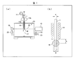
- the original filament 1 containing PVDF is unwound from a state wound on a supply reel 11, and is guided to an orifice 14 via a comb 12.
- the manufacturing apparatus may send the original filament 1 to the orifice 14 at a constant speed by the rotation of the supply reel 11, or may send the original filament 1 to the orifice 14 at a constant speed by the rotation of the feeding nip rollers 13a and 13b. .
- the original filament 1 opened to the outside is placed in an atmospheric pressure environment as the atmospheric pressure P1 before the entrance of the orifice 14 communicating with the stretching chamber 20.
- the extension chamber 20 After the exit of the orifice 14, the extension chamber 20 is placed in an environment having a pressure P2 lower than the pressure P1.
- the original filament 1 delivered to the orifice 14 is guided to the stretching chamber 20 together with high-speed air brought about by a pressure difference between the external pressure P1 and the pressure P2 of the stretching chamber 20.
- the original filament 1 passes through the inside of the region M to which the laser beam (infrared light beam) 30 irradiated from the laser oscillation device 15 is irradiated.
- the original filament 1 is stretched by being heated when passing through the region M, and by being tensioned by high-speed air caused by a pressure difference. Thereby, the nanofiber 2 is formed from the original filament 1.
- the formed nanofibers 2 are stacked on, for example, a conveyor and collected as a nanofiber aggregate or non-woven fabric.
- the internal pressure P2 can be adjusted in the stretching chamber 20 by a duct 21 and a valve 22 communicating with a vacuum pump (not shown). Further, the stretching chamber 20 is provided with a barometer 23 and an output meter 16 for measuring the output of the laser beam 30 irradiated from the laser oscillation device 15.
- the manufacturing apparatus shown in FIG. 1 is only an example of an apparatus for manufacturing nanofibers.
- it is equipped with a supply chamber that communicates with the pressurizing pump, and by incorporating the original filament, reel, comb, nip roller, orifice entrance side, etc. before the orifice entrance into the supply chamber, the atmospheric pressure of the environment before the orifice entrance.
- a manufacturing apparatus capable of setting P1 to a condition other than atmospheric pressure.
- the manufacturing apparatus may be configured to focus the laser beam on the region M by reflecting the laser beam with a mirror, or may be configured to irradiate the laser beam onto the region M from a plurality of light sources.
- the atmospheric pressure difference between the atmospheric pressure P1 of the environment where one end of the original filament is placed and the atmospheric pressure P2 of the drawing chamber where the other end is placed, the environment of the atmospheric pressure P1 and the atmospheric pressure P2 By adjusting the diameter of the orifice that communicates with the drawing chamber, the output of the laser light that irradiates the original filament, the distance from the exit of the orifice to the center point of the region that irradiates the laser light, and the delivery speed of the original filament Manufacture nanofibers. By adjusting these conditions, a PVDF nanofiber having a high ⁇ crystal ratio can be manufactured, and a PVDF nanofiber having an average fiber diameter of 400 nm or less can be manufactured.
- the atmospheric pressure P1 only needs to be higher than the atmospheric pressure P2, and is not limited.
- the atmospheric pressure P1 may be standard atmospheric pressure.
- the atmospheric pressure P2 of the environment where the end (the other end) of the original filament 1 that is sent from the orifice to the drawing chamber is placed is: , 95 kPa or less, more preferably 85 kPa or less.
- the atmospheric pressure P1 is atmospheric pressure and the atmospheric pressure P2 is 95 kPa or less
- nanofibers can be suitably manufactured.
- the atmospheric pressure P1 is atmospheric pressure
- the average fiber diameter of the nanofibers can be further reduced by reducing the atmospheric pressure P2 to less than 85 kPa.
- nanofibers are manufactured using PVDF, nanofibers are suitable even when the pressure P2 is in the range of 50 kPa to 95 kPa. Can be manufactured. That is, even if the airflow obtained by the pressure difference between P1 and P2 does not exceed the speed of sound, the nanofiber can be suitably manufactured. For this reason, the energy required for manufacturing a nanofiber can be reduced. Moreover, the atmospheric pressure conditions for producing nanofibers can be easily managed. That is, the nanofiber can be easily manufactured.
- the nanofiber is manufactured by adjusting the diameter of the orifice that communicates the environment of the atmospheric pressure P1 and the environment of the atmospheric pressure P2.
- the orifice diameter is represented by an orifice diameter D which is an inner diameter of the orifice 14 on the outlet side.
- the orifice diameter D can be appropriately adjusted depending on the fiber diameter of the original filament, and is not limited.
- the orifice diameter D is 1.05 times or more the fiber diameter d of the original filament 1. It is preferable that the diameter is within a range of 10 times or less.
- the nanofiber with a smaller average fiber diameter can be manufactured by increasing the magnification of the orifice diameter D with respect to the fiber diameter d of the original filament 1 shown in FIG.
- the nanofiber is manufactured by adjusting the output of the laser light applied to the original filament.
- the laser light is an infrared light beam having a wavelength of 0.7 ⁇ m to 100 ⁇ m.
- the laser light include a carbon dioxide laser with a wavelength of 10.6 ⁇ m and a YAG (yttrium, aluminum, garnet) laser with a wavelength of 1.06 ⁇ m.
- a carbon dioxide laser with a wavelength of 10.6 ⁇ m
- a YAG (yttrium, aluminum, garnet) laser with a wavelength of 1.06 ⁇ m By irradiating with laser light, PVDF can be suitably heated and melted.
- the output of the laser beam applied to the original filament can be adjusted as appropriate depending on the fiber diameter of the original filament to be used, and is not limited. For example, the average fiber diameter of 10 ⁇ m or more and 1000 ⁇ m or less is used.
- a nanofiber using an original filament it is preferable to irradiate laser light having an output within a range of 1 W or more and 100 W or less, and to irradiate laser light having an output within a range of 5 W or more and 30 W or less. More preferred.
- the center of the original filament can be heated by the laser beam.
- a PVDF nanofiber having an average fiber diameter of 400 nm or less can be suitably manufactured.
- the laser beam is irradiated toward the region M through which the original filament 1 passes.
- the distance L from the exit of the orifice 14 to the center point of the region M where the original filament 1 is irradiated with laser light is adjusted.
- the distance L is appropriately adjusted according to the beam diameter and output of the laser irradiated to the original filament, the atmospheric pressure difference between P1 and P2, and the like, but is not limited. For example, from the exit of the orifice to the center point of the region irradiated with the laser light
- the distance L is preferably in the range of 0.1 mm or more and 10.0 mm or less, and more preferably in the range of 0.2 mm or more and 8.0 mm or less. If the distance L is in the range of 0.1 mm or more and 10.0 mm or less, nanofibers can be suitably manufactured from the original filament containing PVDF. Further, by shortening the distance L, it is possible to manufacture nanofibers having a smaller average fiber diameter.
- the laser beam diameter can be appropriately adjusted in consideration of the laser output and the distance L, but is preferably about 1 mm, for example.
- nanofibers are manufactured by adjusting the delivery speed at which the original filament is delivered in the length direction to the region irradiated with laser light.
- the delivery speed of the original filament is appropriately adjusted according to the pressure difference between P1 and P2, the output of the laser light applied to the original filament, the orifice diameter, and the distance from the exit of the orifice to the center point of the area irradiated with the laser light.
- the speed is preferably within a range of 0.001 m / min or more and 5.0 m / min or less, and preferably within a range of 0.03 m / min or more and 0.8 m / min or less. More preferably, the speed is most preferably in the range of 0.05 m / min to 0.5 m / min.
- the feed speed may be adjusted by adjusting the rotation speed of the supply reel 11 shown in FIG. 1A, or may be adjusted by adjusting the rotation speed of the feeding nip rollers 13a and 13b. Also good.
- the feeding speed may be adjusted by either the supply reel or the feeding nip roller according to the type of the original filament to be stretched. For example, when the original filament is an original filament composed of a single fiber, the original filament is drawn into the orifice due to the pressure difference between P1 and P2, and therefore the original filament is preferably adjusted by adjusting the rotation speed of the supply reel. The filament can be sent out.
- the method for producing an ultrafine fiber of vinylidene fluoride resin heats the original filament containing the vinylidene fluoride resin in the length direction of the original filament with the infrared light beam, The heated original filament is stretched by an air flow along the length direction.
- the air flow has an atmospheric pressure P2 in which the other end is placed rather than an atmospheric pressure P1 in which the one end of the original filament is placed. More preferably, it is caused by lowering.
- the original filament is more preferably an unstretched filament.
- the vinylidene fluoride resin is a homopolymer of vinylidene fluoride monomer or a copolymer containing 50% by mass or more of vinylidene fluoride monomer. More preferably.
- the ultrafine fiber of vinylidene fluoride resin produced by the method for producing an ultrafine fiber of vinylidene fluoride resin according to the present invention is also within the scope of the present invention.
- the proportion of ⁇ crystal in the ultrafine vinylidene fluoride resin is 75% or more.
- the average fiber diameter of the above-mentioned vinylidene fluoride resin ultrafinened of the vinylidene fluoride resin is more preferably 400 nm or less.
- Example 1 Polyvinylidene fluoride KF # 1300 (manufactured by Kureha Co., Ltd.) was used to produce unstretched filaments (diameter 200 ⁇ m) by melt spinning, and the output of laser light (infrared light flux) was changed to produce nanofibers. The crystallinity and ⁇ -crystal ratio (%) of the drawn filament and the nanofiber produced at each laser output were evaluated.
- the nanofiber was manufactured using the manufacturing apparatus shown in FIG.
- the orifice diameter was set to 0.5 mm, and the distance from the exit of the orifice to the center point of the region irradiated with laser light (distance L in FIG. 1B) was set to 1.5 mm.
- P1 is atmospheric pressure, and the pressure P2 in the chamber (stretching chamber) was set to 80 kPa.
- the feed speed of the original filament was set to 0.2 m / min.
- the output of the laser beam for heating the original filament was 8 W, 10 W, 20 W, and 30 W. Nanofibers were produced with each laser output and evaluated.
- the ⁇ crystal ratio was measured by the following method.
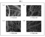
- FIGS. 2A to 2D are photographs obtained by magnifying the nanofibers obtained under the conditions of the laser outputs of 8 W, 10 W, 20 W, and 30 W to 10000 times. 2A to 2D, it was confirmed that nanofibers having a fiber diameter of less than 1 ⁇ m were obtained.
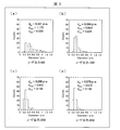
- FIGS. 3A to 3D are graphs showing the average fiber diameter distribution of nanofibers manufactured under each laser output condition in Table 1.
- FIGS. 3A to 3D it was confirmed that the average fiber diameter was 500 ⁇ m or less under any laser output condition.
- nanofibers manufactured under conditions where the laser output is 10 W to 30 W have an average fiber diameter of about 300 nm, and the difference between the maximum and minimum fiber diameters is less than that when manufactured at a laser output of 8 W. It was confirmed to be smaller.
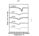
- FIG. 4 shows a graph obtained by measuring the differential scanning calorimetry (DSC) of the nanofiber manufactured under each laser output condition in Table 1.
- “Original” in FIG. 4 refers to an unstretched original filament (200 ⁇ m) produced by KF # 1300.
- FIG. 4 shows a tendency that the endothermic peak around 173.4 ° C. in the original filament of KF # 1300 becomes smaller as the nanofiber is manufactured under a condition where the laser output is high. Further, in all the nanofibers manufactured with a laser output of 8 W, an endothermic peak is confirmed around 160 ° C. In other words, it can be confirmed that the crystal structure transition occurs by irradiating the unstretched KF # 1300 original filament with a laser having an output of 8 W or more to produce a nanofiber.
- Example 2 Using polyvinylidene fluoride KF # 1300 (manufactured by Kureha Co., Ltd.), a drawn filament (diameter: 200 ⁇ m) is produced as an original filament by melt spinning, P1 is set to atmospheric pressure, P2 in the chamber (drawing chamber), and the filament Nanofibers were manufactured by changing the position of laser light irradiation.
- the nanofiber was manufactured using the manufacturing apparatus shown in FIG.
- the orifice diameter was set to 0.5 mm
- the laser output was set to 10 W
- the feed rate of the original filament was set to 0.1 m / min.
- the nanofiber is formed under the condition that the atmospheric pressure P2 in the stretching chamber is 40 kPa, 50 kPa, and 60 kPa.
- Manufactured and evaluated whether or not nanofibers can be manufactured is evaluated by visual observation and SEM (scanning electron microscope) observation, and those that can produce nanofibers are evaluated as “ ⁇ ”, and nanofibers can be produced. Those not present were evaluated as “x”.
- nanofibers can be suitably manufactured under the conditions where the pressure L is 50 kPa or less and the distance L is any condition. Further, it was confirmed that nanofibers can be preferably manufactured by setting the distance L to 1.0 mm or less even under the condition where the atmospheric pressure P2 is 60 kPa.
- Example 3 Using polyvinylidene fluoride KF # 1300 (manufactured by Kureha Co., Ltd.), a drawn filament (diameter 120 ⁇ m) is produced by melt spinning as an original filament, and the pressure P2 in the chamber (drawing chamber), the diameter of the orifice, and The distance L shown in (b) was changed to manufacture nanofibers, and the average fiber diameter of the obtained nanofibers was measured.
- the nanofiber was manufactured using the manufacturing apparatus shown in FIG.
- the laser output was set to 30 W, and the feed speed of the original filament was set to 0.1 m / min.
- P1 is atmospheric pressure.
- the conditions and results of the orifice diameter, distance L, and atmospheric pressure P2 are shown in Table 3 below.
- the average fiber diameter of the nanofibers tends to be smaller when manufactured under the condition of 0.5 mm than when the orifice diameter is 0.3 mm. Moreover, it has confirmed that the nanofiber with a smaller average fiber diameter can be manufactured, so that the distance L is short. Note that nanofibers could not be obtained under the conditions of an orifice diameter of 0.3 mm, a distance L of 2.0 mm, and a pressure of 60 kPa in the chamber.
- Example 4 Polyvinylidene fluoride KF # 1300 (manufactured by Kureha Co., Ltd.) was used to produce a drawn filament (120 ⁇ m in diameter) by melt spinning as the original filament, and the nanofilament was manufactured by changing the feed rate of the original filament, and the average fiber The diameter was measured.
- the nanofiber was manufactured using the manufacturing apparatus shown in FIG.
- the orifice diameter was set to 0.5 mm, the distance L was set to 1.5 mm, and the laser output was set to 30 W.
- P1 was atmospheric pressure, and the atmospheric pressure P2 in the chamber was set to 30 kPa.
- Nanofibers were produced under the conditions of the original filament feed rates of 0.05 mm / min, 0.1 mm / min, and 0.5 mm / min. The results are shown in Table 4 below.
- Example 5 Nanofibers were manufactured using the heat-treated raw filaments, and the average fiber diameter was measured.
- a drawn filament (diameter: 120 ⁇ m) is prepared by melt spinning using KF # 1300 (manufactured by Kureha Co., Ltd.), and then an unheated filament (untreated), 30 ° C., 30 ° C. using the drawn filament.
- a filament heated for 1 minute (treatment 1) and a filament heated at 140 ° C. for 30 minutes (treatment 2) were prepared.
- the nanofiber was manufactured using the manufacturing apparatus shown in FIG.
- the orifice diameter was set to 0.5 mm, the distance L was set to 1.5 mm, the laser output was set to 20 W, and the feed rate of the original filament was set to 0.1 mm / min.
- P1 was atmospheric pressure, and the atmospheric pressure P2 in the chamber was set to 30 kPa.
- the average fiber diameter of the nanofibers obtained using each original filament is shown in Table 5 below.
- Example 6 Polyvinylidene fluoride KF # 1300 (manufactured by Kureha Co., Ltd.) is used to produce unstretched filaments (diameter 200 ⁇ m) by melt spinning, and the conditions of laser output, raw filament delivery speed, and atmospheric pressure P2 in the chamber are changed. The nanofiber was manufactured, and the average fiber diameter of the obtained nanofiber was measured.
- the nanofiber was manufactured using the manufacturing apparatus shown in FIG.
- the orifice diameter was set to 0.5 mm, and the distance L from the exit of the orifice to the center point of the region irradiated with laser light was set to 1.5 mm.
- P1 is atmospheric pressure.
- Table 6 below shows the conditions of the laser output, the delivery speed, and the atmospheric pressure P2 in the chamber, and the average fiber diameter of the nanofibers obtained under these conditions.
- nanofibers could not be manufactured under conditions where the laser output was 5 W, the delivery speed was 0.1 mm, and the atmospheric pressure in the chamber was 60 kPa. However, the pressure in the chamber was reduced to 30 kPa from the conditions under which the nanofiber could not be manufactured, the conditions under which the laser output was increased to 10 W, and the condition under which the nanofiber could not be manufactured. It has been confirmed that nanofibers can be suitably manufactured under the manufacturing conditions.
- Example 7 Using polyvinylidene fluoride KF # 1300 (manufactured by Kureha Co., Ltd.), an unstretched filament (diameter: 200 ⁇ m) is prepared by melt spinning, and the distance L from the exit of the orifice to the center point of the region irradiated with the laser beam, and The nanofiber was manufactured by changing the pressure P2 in the chamber, and the average fiber diameter of the obtained nanofiber was measured.
- the nanofiber was manufactured using the manufacturing apparatus shown in FIG.
- the orifice diameter was set to 0.5 mm
- the laser output was set to 10 W
- the feed rate of the original filament was set to 0.2 m / min.
- P1 is atmospheric pressure.
- Table 7 below shows the conditions of the distance L and the atmospheric pressure P2 in the chamber, and the average fiber diameter of the nanofibers obtained under these conditions.
- Example 8 Polyvinylidene fluoride KF # 1300 (manufactured by Kureha Co., Ltd.) is used to produce unstretched filaments (diameter 200 ⁇ m) by melt spinning, to produce nanofibers by changing the orifice diameter and pressure P2 in the chamber, The average fiber diameter of the obtained nanofiber was measured.
- the nanofiber was manufactured using the manufacturing apparatus shown in FIG.
- the laser output was set to 10 W
- the distance L was set to 1.5 mm
- the feed speed of the original filament was set to 0.2 m / min.
- P1 is atmospheric pressure.
- Table 8 below shows the orifice diameter, the conditions of the pressure P2 in the chamber, and the average fiber diameter of the nanofibers obtained under these conditions.
- Example 9 Using polyvinylidene fluoride KF # 1300 (manufactured by Kureha Co., Ltd.), an unstretched filament (diameter: 200 ⁇ m) is prepared by melt spinning, and the distance L from the exit of the orifice to the center point of the region irradiated with the laser beam, and The nanofiber was manufactured by changing the pressure P2 in the chamber, and the average fiber diameter of the obtained nanofiber was measured.
- the nanofiber was manufactured using the manufacturing apparatus shown in FIG.
- the orifice diameter was set to 1.0 mm
- the laser output was set to 10 W
- the feed rate of the original filament was set to 0.2 m / min.
- P1 is atmospheric pressure.
- Table 9 below shows the conditions of the distance L and the atmospheric pressure P2 in the chamber, and the average fiber diameter of the nanofibers obtained under these conditions.
- a nanofiber having a ⁇ crystal ratio of 75% or more can be manufactured using PVDF.
- a nanofiber made of PVDF having an average fiber diameter of 700 nm or less, in particular, an average fiber diameter of 400 nm or less by adjusting various conditions such as an orifice diameter and a laser output. I was able to confirm that
- the present invention can be used for producing nanofibers of vinylidene fluoride resin.
Landscapes
- Engineering & Computer Science (AREA)
- Textile Engineering (AREA)
- Chemical & Material Sciences (AREA)
- Chemical Kinetics & Catalysis (AREA)
- General Chemical & Material Sciences (AREA)
- Artificial Filaments (AREA)
- Yarns And Mechanical Finishing Of Yarns Or Ropes (AREA)
- Nonwoven Fabrics (AREA)
Abstract
フッ化ビニリデン系樹脂を含んでいる極細ファイバを首尾よく製造する。フッ化ビニリデン系樹脂を含んでいる原フィラメントを当該原フィラメントの長さ方向に送り出しつつ赤外線光束により加熱し、加熱された当該原フィラメントを当該長さ方向に沿う気流により延伸する。
Description
本発明は、フッ化ビニリデン系樹脂の極細ファイバの製造方法及び、フッ化ビニリデン系樹脂の極細ファイバに関する。
繊維径が1μm未満、すなわちナノメータ(数ナノメータから数百ナノメータ)範囲であるフッ化ビニリデン系樹脂の極細ファイバは、各種フィルタ、固体高分子形燃料電池用電解質膜の補強材等として有用であり、IT、バイオ、環境分野などの幅広い分野で将来の革新的素材になると注目されている。
特許文献1には、フッ化ビニリデン系樹脂を溶媒に溶解して紡糸溶液を製造する段階と、エレクトロスピニング法(ES法)によって、紡糸溶液から疎水性高分子ナノ繊維ウェブを得る段階とを包含するメンブレンの製造方法が記載されている。
特許文献2には、フッ化ビニリデン系樹脂と他の樹脂を混合して溶融延伸し、溶剤によりフッ化ビニリデン系樹脂に混合された他の樹脂を除去することにより、極細繊維状物を製造する方法が記載されている。
特許文献3には、フッ化ビニリデン系樹脂を含んでいるナノ繊維層をメルトブローイング法又はエレクトロブローイング法により製造することが記載されている。
しかしながら、特許文献1に記載されているようなエレクトロスピニング法、及び特許文献3に記載されているようなエレクトロブローイング法、並びに、特許文献2に記載されているような、極細ファイバの製造方法では、溶媒を用いてポリフッ化ビニリデン系樹脂の極細ファイバを製造する。このため、用途によっては、極細ファイバから溶剤を除去することが必要になるという問題がある。
また、特許文献3に記載されているようなメルトブローイング法では、フッ化ビニリデン系樹脂から製造された極細ファイバが互いに融着せず、不織布を形成することが困難になることがあるという問題がある。
本発明は上記の問題に鑑みてなされたものであり、その目的は、フッ化ビニリデン系樹脂を含んでいる極細ファイバを首尾よく製造する方法を提供することにある。
上記の課題を解決するために、本発明に係るフッ化ビニリデン系樹脂の極細ファイバの製造方法は、フッ化ビニリデン系樹脂を含んでいる原フィラメントを当該原フィラメントの長さ方向に送り出しつつ赤外線光束により加熱し、加熱された当該原フィラメントを当該長さ方向に沿う気流により延伸することを特徴としている。
本発明によれば、フッ化ビニリデン系樹脂を含んでいる極細ファイバを首尾よく製造することができるという効果を奏する。
<フッ化ビニリデン系樹脂の極細ファイバの製造方法>
本発明の一実施形態に係るナノファイバ(極細ファイバ)の製造方法は、フッ化ビニリデン系樹脂を含んでいる原フィラメントをその原フィラメントの長さ方向に送り出しつつ赤外線光束により加熱し、加熱された原フィラメントを長さ方向に沿う気流により延伸する。長さ方向に沿う気流は、原フィラメントの一方の端部が置かれる環境の気圧P1よりも、他方の端部が置かれる環境の気圧P2を低くすることで生じさせることが好ましい。本実施形態では、以下、気圧差により気流を生じさせる場合を例に挙げて説明する。
本発明の一実施形態に係るナノファイバ(極細ファイバ)の製造方法は、フッ化ビニリデン系樹脂を含んでいる原フィラメントをその原フィラメントの長さ方向に送り出しつつ赤外線光束により加熱し、加熱された原フィラメントを長さ方向に沿う気流により延伸する。長さ方向に沿う気流は、原フィラメントの一方の端部が置かれる環境の気圧P1よりも、他方の端部が置かれる環境の気圧P2を低くすることで生じさせることが好ましい。本実施形態では、以下、気圧差により気流を生じさせる場合を例に挙げて説明する。
本発明の一実施形態に係るナノファイバの製造方法は、従来のナノファイバの製法であるES法やエレクトロブローイング法と異なり、フッ化ビニリデン系樹脂をクロロホルムなどの溶剤に溶解することなく使用することができるため、脱溶剤が不要である。このため、有害溶剤の使用が望まれない、医療分野において使用することができるナノファイバを製造することができる。従って、フッ化ビニリデン系樹脂を含んでいる原フィラメントを極細化したナノファイバを首尾よく製造することができる。
また、一実施形態に係るナノファイバの製造方法では、溶融紡糸により製造されたフッ化ビニリデン系樹脂を含む原フィラメントを延伸し、ナノファイバを製造した後、当該ナノファイバを互いに融着させることができる。つまり、一実施形態に係るナノファイバの製造方法によれば、溶剤を含まないポリフッ化ビニリデン系樹脂を用いてナノファイバからなる不織布を首尾よく製造することができる。
また、一実施形態に係るナノファイバの製造方法によれば、平均繊維径が500nm以下であるナノファイバ(極細ファイバ)を製造することができる。当該ナノファイバは、繊維径分布が狭く、長さが数m以上であり、このような、フッ化ビニリデン系樹脂を含むナノファイバからなる不織布を好適に製造することができる。
なお、本明細書中において、「ナノファイバ」とは、平均繊維径が1μmよりも小さい繊維のことを意味する。
〔フッ化ビニリデン系樹脂〕
本明細書において、フッ化ビニリデン系樹脂(単に「PVDF」という)には、フッ化ビニリデン(VDF)の単独重合体、および、VDFと他のモノマーとの共重合体を包含し、一つの樹脂に含有されるモノマーの種類と数に限りはない。ここで、他のモノマーとしては、VDFと共重合可能であれば如何なるモノマーでもよい。一例を挙げるとすれば、トリフルオロエチレン(TrFE)、クロロトリフルオロエチレン(CTFE)、ヘキサフルオロプロピレン(HFP)、テトラフルオロエチレン(TFE)などのフッ素系モノマー、エチレン、プロピレンなどの炭化水素系モノマー、アクリル酸などカルボキシル基含有モノマー、無水マレイン酸などカルボン酸無水物基含有モノマーなどが挙げられ、より好ましくは、トリフルオロエチレン(TrFE)などを挙げることができる。このようなモノマーであれば、VDFと共重合させることによりβ晶の割合が高いナノファイバを製造することができる原フィラメントを得ることができる。また、これら他のモノマーに対するVDFの比率を高めるか、他のモノマーとしてTrFEなどをVDFと共重合させるかにより、PVDFにおけるβ晶の比率をより高くすることができる。
本明細書において、フッ化ビニリデン系樹脂(単に「PVDF」という)には、フッ化ビニリデン(VDF)の単独重合体、および、VDFと他のモノマーとの共重合体を包含し、一つの樹脂に含有されるモノマーの種類と数に限りはない。ここで、他のモノマーとしては、VDFと共重合可能であれば如何なるモノマーでもよい。一例を挙げるとすれば、トリフルオロエチレン(TrFE)、クロロトリフルオロエチレン(CTFE)、ヘキサフルオロプロピレン(HFP)、テトラフルオロエチレン(TFE)などのフッ素系モノマー、エチレン、プロピレンなどの炭化水素系モノマー、アクリル酸などカルボキシル基含有モノマー、無水マレイン酸などカルボン酸無水物基含有モノマーなどが挙げられ、より好ましくは、トリフルオロエチレン(TrFE)などを挙げることができる。このようなモノマーであれば、VDFと共重合させることによりβ晶の割合が高いナノファイバを製造することができる原フィラメントを得ることができる。また、これら他のモノマーに対するVDFの比率を高めるか、他のモノマーとしてTrFEなどをVDFと共重合させるかにより、PVDFにおけるβ晶の比率をより高くすることができる。
また、本発明で用いるPVDFは、1種類の重合体であってもよいし、2種類以上の重合体の混合物であってもよい。2種以上の重合体の混合物及び共重合体を用いる場合も含め、フッ化ビニリデンの共重合体におけるフッ化ビニリデンモノマーの含有量は、50質量%以上、100質量%以下の範囲内の含有量であることが好ましく、60質量%以上、100質量%以下の範囲内の含有量であることがより好ましく、90質量%以上、100質量%以下の範囲内の含有量であることがより好ましい。フッ化ビニリデンの共重合体におけるフッ化ビニリデンモノマーの含有量が、50質量%以上、100質量%以下の範囲内の含有量であれば、β晶比率が75%以上のPVDFのナノファイバを製造することができる原フィラメントを得ることができる。
PDVFを含んでいる原フィラメントを用いることにより、含フッ素樹脂のなかでも、β晶の割合が高いナノファイバを好適に製造することができる。特に、PVDFは、VDFの単独重合体、又は、VDFとTrFEとの共重合体からなるものであることがより好ましい。VDFの単独重合体、又は、VDFとTrFEとの共重合体からなる原フィラメントを用いて、ナノファイバを製造することで、さらにナノファイバにおけるβ晶の割合を高めることができ、ナノファイバに、高い圧電性、焦電性、及び強誘電性もたらすことができる。従って、医療用途やセンシング用途に好適に用いることができるナノファイバを製造できることが期待される。
なお、PVDFは、他の成分として、着色防止剤やフェノール系安定剤、色素、機能性粒子などの添加剤を含んでいてもよい。
PVDFは、商業的に入手可能なものを用いることができる。例えば、商業的に入手できる粉末状のPVDFを加熱により溶融し、原フィラメントを成形した後に、本発明に係る製造方法により、ナノファイバを製造するために用いるとよい。
〔原フィラメント〕
原フィラメントは、PVDFを含んでいるフィラメントであり、ナノファイバを成形するために用いられる。原フィラメントは、実質的に連続した繊維であり、数ミリメータから数十ミリメータの長さである短繊維とは区別される。また、原フィラメントは、PVDFを含んでいる1本の繊維であることが好ましいが、数本ないし数十本の繊維を集合させたマルチフィラメントを使用してもよい。フィラメントは、組成や分子量の異なる2つのPVDFから成る、芯鞘構造や海島構造であってもよく、PVDFと他の樹脂とから成る芯鞘構造や海島構造であってもよい。原フィラメントとして、PVDFと他の樹脂との組合せによる芯鞘構造を備えたフィラメントを採用する場合、原フィラメントは芯鞘構造における芯部又は鞘部のいずれかをPVDFにより形成されていればよい。同様に、海島構造を備えたフィラメントを採用する場合、原フィラメントは海島構造における海部又は島部のいずれかをPVDFにより形成されていればよい。また、原フィラメントには予め加熱処理を行なったものを用いることもできる。
原フィラメントは、PVDFを含んでいるフィラメントであり、ナノファイバを成形するために用いられる。原フィラメントは、実質的に連続した繊維であり、数ミリメータから数十ミリメータの長さである短繊維とは区別される。また、原フィラメントは、PVDFを含んでいる1本の繊維であることが好ましいが、数本ないし数十本の繊維を集合させたマルチフィラメントを使用してもよい。フィラメントは、組成や分子量の異なる2つのPVDFから成る、芯鞘構造や海島構造であってもよく、PVDFと他の樹脂とから成る芯鞘構造や海島構造であってもよい。原フィラメントとして、PVDFと他の樹脂との組合せによる芯鞘構造を備えたフィラメントを採用する場合、原フィラメントは芯鞘構造における芯部又は鞘部のいずれかをPVDFにより形成されていればよい。同様に、海島構造を備えたフィラメントを採用する場合、原フィラメントは海島構造における海部又は島部のいずれかをPVDFにより形成されていればよい。また、原フィラメントには予め加熱処理を行なったものを用いることもできる。
原フィラメントは、例えば、溶融紡糸により製造することができる。原フィラメントの平均繊維径は、原フィラメントを延伸する条件により適宜調整することができるが、例えば、10μm以上、1000μm以下の範囲内であることが好ましく、50μm以上、800μm以下の範囲内であることが好ましく、100μm以上、500μm以下の範囲内であることが最も好ましい。原フィラメントの平均繊維径が10μm以上、1000μm以下の範囲内であれば、原フィラメントがレーザ光(赤外線光束)によって加熱されたときに溶け落ちることを防止することができる。また、平均繊維径が400nm以下であるPVDFのナノファイバを好適に製造することができる。
原フィラメントは、当該原フィラメントを延伸することによって10μm以上、1000μm以下の範囲内の平均繊維径に予め成形したものを用いてもよいが、未延伸の状態で当該範囲内の平均繊維径になるよう成形されたものを用いることがより好ましい。一実施形態に係る製造方法によれば、未延伸のPVDFの原フィラメントを用いることにより、400nm以下の平均繊維径のナノファイバを製造することができる。
また、別の観点において、一実施形態に係るナノファイバの製造方法によれば、原フィラメントを予め延伸する前工程を行なわなくても、β晶の割合が高いナノファイバを製造することができる。
〔製造装置〕
一実施形態に係るナノファイバの製造方法は、図1の(a)に示す製造装置を用いて実施することができる。
一実施形態に係るナノファイバの製造方法は、図1の(a)に示す製造装置を用いて実施することができる。
図1の(a)に示すように、製造装置において、PVDFを含んでいる原フィラメント1は供給リール11に巻かれた状態から繰り出され、コーム12を経て、オリフィス14へと導かれる。ここで、製造装置は、供給リール11の回転により原フィラメント1をオリフィス14まで一定速度で送り出してもよく、繰出ニップローラ13a、13bの回転により原フィラメント1をオリフィス14まで一定速度で送り出してもよい。
なお、図1の(a)に示すように、延伸室20に連通するオリフィス14の入り口以前において、外部に開放された原フィラメント1は、気圧P1として大気圧の環境に置かれている。
オリフィス14の出口以降は、気圧P1よりも低い気圧P2の環境下に置かれた延伸室20となる。オリフィス14に送り出された原フィラメント1は、外部の気圧P1と延伸室20の気圧P2との気圧差によってもたらされる高速エアーと共に延伸室20に導かれる。
ここで、図1の(a)及び(b)に示すように、原フィラメント1は、レーザ発振装置15から照射されたレーザ光(赤外線光束)30が照射される領域Mの内側を通過する。
原フィラメント1は、領域Mを通過するときに加熱されること、及び、気圧差によってもたらされる高速エアーにより張力を与えられることにより延伸される。これにより、原フィラメント1からナノファイバ2が形成される。形成されたナノファイバ2は、例えば、コンベアなどの上に積層され、ナノファイバの集積体又は不織布として回収される。
なお、延伸室20には、真空ポンプ(不図示)に連通するダクト21及びバルブ22によって、内部の気圧P2を調整することができるようになっている。また、延伸室20には、気圧計23、及び、レーザ発振装置15から照射されたレーザ光30の出力を計測する出力計16が設けられている。
(他の製造装置)
図1に示す製造装置は、ナノファイバを製造するための装置の一例にすぎない。例えば、加圧ポンプに連通する供給室を備え、オリフィスの入り口以前における原フィラメント、リール、コーム、ニップローラ、オリフィスの入り口側などを当該供給室に内蔵することで、オリフィスの入り口以前における環境の気圧P1を大気圧以外の条件にすることも可能な製造装置を用いてナノファイバを製造することも可能である。
図1に示す製造装置は、ナノファイバを製造するための装置の一例にすぎない。例えば、加圧ポンプに連通する供給室を備え、オリフィスの入り口以前における原フィラメント、リール、コーム、ニップローラ、オリフィスの入り口側などを当該供給室に内蔵することで、オリフィスの入り口以前における環境の気圧P1を大気圧以外の条件にすることも可能な製造装置を用いてナノファイバを製造することも可能である。
また、製造装置は、レーザ光を鏡で反射することで領域Mに集光する構成であってもよく、複数の光源から領域Mにレーザ光を照射する構成であってもよい。
〔製造条件〕
一実施形態に係るナノファイバの製造方法では、原フィラメント一方の端部が置かれる環境の気圧P1と他方の端部が置かれる延伸室の気圧P2との気圧差、気圧P1の環境と気圧P2の延伸室とを連通させるオリフィスの径、原フィラメントに照射するレーザ光の出力、オリフィスの出口からレーザ光を照射する領域の中心点までの距離、及び、原フィラメントの送り出し速度を調整することによってナノファイバを製造する。これらの条件を調整することにより、β晶比率が高いPVDFのナノファイバを製造することができ、平均繊維径が特に400nm以下であるPVDFのナノファイバを製造することができる。
一実施形態に係るナノファイバの製造方法では、原フィラメント一方の端部が置かれる環境の気圧P1と他方の端部が置かれる延伸室の気圧P2との気圧差、気圧P1の環境と気圧P2の延伸室とを連通させるオリフィスの径、原フィラメントに照射するレーザ光の出力、オリフィスの出口からレーザ光を照射する領域の中心点までの距離、及び、原フィラメントの送り出し速度を調整することによってナノファイバを製造する。これらの条件を調整することにより、β晶比率が高いPVDFのナノファイバを製造することができ、平均繊維径が特に400nm以下であるPVDFのナノファイバを製造することができる。
(気圧差)
原フィラメントが延伸室に送り出される前における環境の気圧P1よりも、原フィラメントが延伸室に送り出された後の環境の気圧P2を低くすることによって、気圧P1と気圧P2との気圧差により生じる原フィラメントの長さ方向に沿う気流により、レーザ光により加熱された原フィラメントを延伸する。これにより、高速気体流の流れを安定させることができ、PVDFを含んでいるナノファイバを連続的に製造することができる。
原フィラメントが延伸室に送り出される前における環境の気圧P1よりも、原フィラメントが延伸室に送り出された後の環境の気圧P2を低くすることによって、気圧P1と気圧P2との気圧差により生じる原フィラメントの長さ方向に沿う気流により、レーザ光により加熱された原フィラメントを延伸する。これにより、高速気体流の流れを安定させることができ、PVDFを含んでいるナノファイバを連続的に製造することができる。
気圧P1は、気圧P2よりも高ければよく、限定されるものではないが、例えば、標準大気圧にするとよい。
これに対して、例えば、P1が大気圧(101.3kPa)である場合、原フィラメント1におけるオリフィスから延伸室に送り出された側の端部(他方の端部)が置かれる環境の気圧P2は、95kPa以下であることが好ましく、85kPa以下であることがより好ましい。気圧P1が大気圧であるときに、気圧P2が95kPa以下であれば、好適にナノファイバを製造することができる。また、気圧P1が大気圧であるときに、気圧P2を85kPaよりも低くすれば、ナノファイバの平均繊維径をより小さくすることができる。
また、別の観点から、一実施形態に係るナノファイバの製造方法では、PVDFを用いてナノファイバを製造するため、気圧P2が50kPa以上、95kPa以下の範囲内であっても、ナノファイバを好適に製造することができる。つまり、P1とP2との気圧差により得られる気流が音速を超えない条件であっても、ナノファイバを好適に製造することができる。このため、ナノファイバを製造するために要するエネルギーを低減することができる。また、ナノファイバを製造するための気圧条件を容易に管理することができる。つまり、ナノファイバを容易に製造することができる。
(オリフィス径)
一実施形態に係るナノファイバの製造方法では、気圧P1の環境と気圧P2の環境とを連通させるオリフィスの径を調整することによってナノファイバを製造する。
一実施形態に係るナノファイバの製造方法では、気圧P1の環境と気圧P2の環境とを連通させるオリフィスの径を調整することによってナノファイバを製造する。
図1の(b)に示すように、オリフィス径は、オリフィス14における出口側の内径であるオリフィス径Dにより表される。オリフィス径Dは、原フィラメントの繊維径により適宜調整することができるため、限定されるものではないが、例えば、オリフィス径Dは、原フィラメント1の繊維径dに対して、1.05倍以上、10倍以下の範囲内の倍率の径であることが好ましい。また、図1の(b)に示す原フィラメント1の繊維径dに対するオリフィス径Dの倍率をより大きくすることで、より平均繊維径が小さいナノファイバを製造することができる。
(レーザ光)
一実施形態に係るナノファイバの製造方法では、原フィラメントに照射するレーザ光の出力を調整することによりナノファイバを製造する。
一実施形態に係るナノファイバの製造方法では、原フィラメントに照射するレーザ光の出力を調整することによりナノファイバを製造する。
レーザ光は、波長0.7μm~100μmの赤外線光束である。また、レーザ光には、一例として、10.6μmの波長の炭酸ガスレーザや、1.06μmの波長のYAG(イットリウム、アルミニウム、ガーネット系)レーザを挙げることができる。レーザ光を照射することにより、PVDFを好適に加熱することができ、融解することができる。ここで、原フィラメントに照射するレーザ光の出力は、使用する原フィラメントの繊維径により適宜調整することができるため、限定されるものではないが、例えば、10μm以上、1000μm以下の平均繊維径の原フィラメントを用いてナノファイバを製造する場合、1W以上、100W以下の範囲内の出力のレーザ光を照射することが好ましく、5W以上、30W以下の範囲内の出力のレーザ光を照射することがより好ましい。1W以上、100W以下の範囲内の出力のレーザ光を照射することによって、原フィラメントの中心までレーザ光によって加熱することができる。また、1W以上、100W以下の範囲内の出力のレーザ光を、PVDFを含んでいる原フィラメントに照射することで、平均繊維径が、400nm以下のPVDFのナノファイバを好適に製造ることができる。なお、図1の(b)に示すように、レーザ光は原フィラメント1が通過する領域Mに向かって照射される。
(レーザ光を照射する領域)
図1の(b)に示すように、一実施形態に係るナノファイバの製造方法では、オリフィス14の出口から原フィラメント1にレーザ光を照射する領域Mの中心点までの距離Lを調整する。
図1の(b)に示すように、一実施形態に係るナノファイバの製造方法では、オリフィス14の出口から原フィラメント1にレーザ光を照射する領域Mの中心点までの距離Lを調整する。
距離Lは、原フィラメントに照射するレーザのビーム径や出力、P1とP2との気圧差などにより適宜調整するため、限定されないが、例えば、オリフィスの出口からレーザ光を照射する領域の中心点までの距離Lは、0.1mm以上、10.0mm以下の範囲内であることが好ましく、0.2mm以上、8.0mm以下の範囲内であることがより好ましい。距離Lが、0.1mm以上、10.0mm以下の範囲内であれば、PVDFを含んでいる原フィラメントからナノファイバを好適に製造することができる。また、距離Lを短くすることで、より平均繊維径が小さいナノファイバを製造することができる。
なお、レーザのビーム径は、レーザの出力や距離Lを考慮して適宜調整することができるが、例えば、1mm程度であることが好ましい。
(送り出し速度)
一実施形態に係るナノファイバの製造方法では、レーザ光を照射する領域にまで原フィラメントを長さ方向に送り出す、送り出し速度を調整することにより、ナノファイバを製造する。
一実施形態に係るナノファイバの製造方法では、レーザ光を照射する領域にまで原フィラメントを長さ方向に送り出す、送り出し速度を調整することにより、ナノファイバを製造する。
原フィラメントの送り出し速度は、P1とP2との気圧差、原フィラメントに照射するレーザ光の出力、オリフィス径、及び、オリフィスの出口からレーサ光が照射される領域の中心点までの距離により適宜調整することができるが、0.001m/min以上、5.0m/min以下の範囲内の速度であることが好ましく、0.03m/min以上、0.8m/min以下の範囲内であることがより好ましく、0.05m/min以上、0.5m/min以下の範囲内の速度であることが最も好ましい。
なお、送り出し速度は、図1の(a)に示す、供給リール11の回転速度を調整することで調整してもよく、又は、繰出ニップローラ13a、13bの回転速度を調整することで調整してもよい。送り出し速度は、延伸する原フィラメントの種類に応じて、供給リールと繰出ニップローラとの何れかによって調整するとよい。例えば、原フィラメントが1本の繊維からなる原フィラメントである場合、当該原フィラメントは、P1とP2との気圧差によりオリフィスに引き込まれるため、供給リールの回転速度を調整することで好適に当該原フィラメントを送り出すことができる。
以上のように、本発明に係るフッ化ビニリデン系樹脂の極細ファイバの製造方法は、フッ化ビニリデン系樹脂を含んでいる原フィラメントを当該原フィラメントの長さ方向に送り出しつつ赤外線光束により加熱し、加熱された当該原フィラメントを当該長さ方向に沿う気流により延伸することを特徴としている。
本発明に係るフッ化ビニリデン系樹脂の極細ファイバの製造方法では、上記気流は、上記原フィラメントの一方の端部が置かれる環境の気圧P1よりも、他方の端部が置かれる環境の気圧P2を低くすることにより生じさせることがより好ましい。
本発明に係るフッ化ビニリデン系樹脂の極細ファイバの製造方法では、上記原フィラメントは、未延伸のフィラメントであることがより好ましい。
本発明に係るフッ化ビニリデン系樹脂の極細ファイバの製造方法では、上記フッ化ビニリデン系樹脂は、フッ化ビニリデンモノマーの単独重合体、又は、フッ化ビニリデンモノマーを50質量%以上含む共重合体であることがより好ましい。
本発明に係るフッ化ビニリデン系樹脂の極細ファイバの製造方法により製造される、フッ化ビニリデン系樹脂の極細ファイバも本発明の範疇である。
本発明に係るフッ化ビニリデン系樹脂の極細ファイバは、極細化された上記フッ化ビニリデン系樹脂におけるβ晶の割合が、75%以上であることがより好ましい。
本発明に係るフッ化ビニリデン系樹脂の極細ファイバは、フッ化ビニリデン系樹脂の極細化された上記フッ化ビニリデン系樹脂の平均繊維径が、400nm以下であることがより好ましい。
本発明は上述した各実施形態に限定されるものではなく、請求項に示した範囲で種々の変更が可能であり、異なる実施形態にそれぞれ開示された技術的手段を適宜組み合わせて得られる実施形態についても本発明の技術的範囲に含まれる。
〔実施例1〕
ポリフッ化ビニリデンKF#1300(株式会社クレハ製)を用いて、溶融紡糸により未延伸フィラメント(直径200μm)を作製し、レーザ光(赤外線光束)の出力を変更してナノファイバの製造を行ない、未延伸フィラメント、及び、各レーザ出力において製造されたナノファイバの結晶化度及びβ晶比率(%)を評価した。
ポリフッ化ビニリデンKF#1300(株式会社クレハ製)を用いて、溶融紡糸により未延伸フィラメント(直径200μm)を作製し、レーザ光(赤外線光束)の出力を変更してナノファイバの製造を行ない、未延伸フィラメント、及び、各レーザ出力において製造されたナノファイバの結晶化度及びβ晶比率(%)を評価した。
ナノファイバの製造は、図1の(a)に示す製造装置を用いて行なった。オリフィス径を0.5mmに設定し、オリフィスの出口からレーザ光を照射する領域の中心点までの距離(図1の(b)における距離L)を1.5mmになるように設定した。P1は大気圧であり、チャンバ(延伸室)における気圧P2を80kPaに設定した。また、原フィラメントの送り出し速度は0.2m/minに設定した。
原フィラメントを加熱するレーザ光の出力は、8W、10W、20W、30Wであり、それぞれのレーザ出力でナノファイバを製造し、評価を行なった。
β晶比率の測定は以下の方法で行なった。
β晶比率(%)の測定:
IRを用い、以下の式に基づき算出した(参考文献:Journal of Polymer Science: PartB: PolymerPhysics Vol32 859-870 (1994))。
β晶比率(%)=β/(1.3α+β)
α=766cm-1におけるα晶の吸光度
β=840cm-1におけるβ晶の吸光度
結果を以下の表1に示す。
IRを用い、以下の式に基づき算出した(参考文献:Journal of Polymer Science: PartB: PolymerPhysics Vol32 859-870 (1994))。
β晶比率(%)=β/(1.3α+β)
α=766cm-1におけるα晶の吸光度
β=840cm-1におけるβ晶の吸光度
結果を以下の表1に示す。

表1に示すように、平均繊維径200μmの原フィラメントにおけるβ晶比率が、26.8%であるのに対して、出力が8Wから30Wのレーザ光を照射することにより製造された、ナノファイバはβ晶比率が75%以上であることが確認された。
図2の(a)~(d)は、表1における各レーザ出力条件において製造されたナノファイバの電子顕微鏡写真である。図2の(a)~(d)は、レーザ出力8W、10W、20W及び30Wの条件で得られたナノファイバを10000倍に拡大して撮影したものである。図2の(a)~(d)では、繊維径が1μm未満のナノファイバが得られていることを確認できた。
図3の(a)~(d)は、表1における各レーザ出力条件において製造されたナノファイバの平均繊維径分布を示すグラフである。図3の(a)~(d)に示すように、いずれのレーザ出力条件においても、平均繊維径が500μm以下であることが確認された。特に、レーザ出力が10W~30Wの条件において製造したナノファイバは、平均繊維径が300nm前後の値であり、レーザ出力8Wにおいて製造する場合よりも、繊維径の最大値と最小値との差が小さくなることが確認された。
図4に、表1における各レーザ出力条件において製造されたナノファイバの示差走査熱量(DSC)の測定により得られたグラフを示す。なお、図4のOriginalとは、KF#1300により作製された未延伸の原フィラメント(200μm)のことを指す。図4では、KF#1300の原フィラメントにおける173.4℃近辺の吸熱ピークが、レーザ出力が高い条件で製造されたナノファイバであるほど小さくなる傾向が示されている。また、8Wのレーザ出力で製造した全てのナノファイバにおいて、160℃近辺において吸熱ピークが確認されている。つまり、未延伸のKF#1300の原フィラメントに8W以上の出力のレーザを照射してナノファイバを製造することにより、結晶構造の転移が生じることを確認できる。
〔実施例2〕
ポリフッ化ビニリデンKF#1300(株式会社クレハ製)を用いて、溶融紡糸により原フィラメントとして延伸フィラメント(直径200μm)を作製し、P1を大気圧とし、チャンバ(延伸室)における気圧P2、及びフィラメントにレーザ光を照射する位置を変更してナノファイバの製造を行なった。
ポリフッ化ビニリデンKF#1300(株式会社クレハ製)を用いて、溶融紡糸により原フィラメントとして延伸フィラメント(直径200μm)を作製し、P1を大気圧とし、チャンバ(延伸室)における気圧P2、及びフィラメントにレーザ光を照射する位置を変更してナノファイバの製造を行なった。
ナノファイバの製造は、図1の(a)に示す製造装置を用いて行なった。オリフィス径は0.5mm、レーザ出力を10Wに設定し、原フィラメントの送り出し速度を0.1m/minに設定した。図1の(b)に示す距離Lが0.5mm、1.0mm、1.5mm及び2.0mmになる条件ごとに、延伸室における気圧P2が40kPa、50kPa、60kPaとなる条件でナノファイバを製造し、ナノファイバの製造の可否を評価した。各条件におけるナノファイバの製造の可否は目視、SEM(scanning electron microscope)観察にて評価し、ナノファイバを製造することができたものを「○」として評価し、ナノファイバを製造することができなかったものを「×」として評価した。
結果を以下の表2に示す。

表2に示すように、気圧P2が50kPa以下の条件では、距離Lがいずれの条件においても、好適にナノファイバを製造することができることを確認できた。また、気圧P2が、60kPaの条件においても、距離Lを1.0mm以下にすることによって、好適にナノファイバを製造することができることを確認できた。
〔実施例3〕
ポリフッ化ビニリデンKF#1300(株式会社クレハ製)を用いて、原フィラメントとして溶融紡糸により延伸フィラメント(直径120μm)を作製し、チャンバ(延伸室)における気圧P2、オリフィスの径、及び、図1の(b)に示す距離Lを変更してナノファイバの製造し、得られたナノファイバの平均繊維径を測定した。
ポリフッ化ビニリデンKF#1300(株式会社クレハ製)を用いて、原フィラメントとして溶融紡糸により延伸フィラメント(直径120μm)を作製し、チャンバ(延伸室)における気圧P2、オリフィスの径、及び、図1の(b)に示す距離Lを変更してナノファイバの製造し、得られたナノファイバの平均繊維径を測定した。
ナノファイバの製造は、図1の(a)に示す製造装置を用いて行なった。レーザ出力を30Wに設定し、原フィラメントの送り速度を0.1m/minに設定した。なお、P1は大気圧である。オリフィス径、距離L及び気圧P2の条件及び結果を以下の表3に示す。
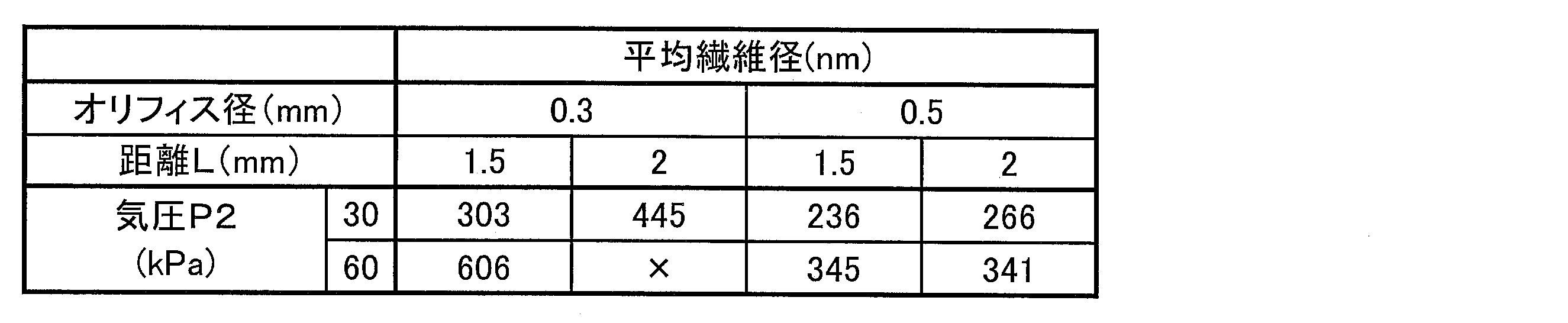
表3に示すように、オリフィス径が0.3mmの条件よりも、0.5mmの条件において製造するほうが、ナノファイバの平均繊維径は小さくなる傾向であることを確認できた。また、距離Lが短いほうがより平均繊維径の小さいナノファイバを製造することができることを確認できた。なお、オリフィス径が0.3mm、距離Lが2.0mm、チャンバ内の気圧60kPaの条件では、ナノファイバを得ることができなかった。
〔実施例4〕
ポリフッ化ビニリデンKF#1300(株式会社クレハ製)を用いて、原フィラメントとして溶融紡糸により延伸フィラメント(直径120μm)を作成し、原フィラメントの送り出し速度を変化させて、ナノファイバを製造し、平均繊維径を測定した。
ポリフッ化ビニリデンKF#1300(株式会社クレハ製)を用いて、原フィラメントとして溶融紡糸により延伸フィラメント(直径120μm)を作成し、原フィラメントの送り出し速度を変化させて、ナノファイバを製造し、平均繊維径を測定した。
ナノファイバの製造は、図1の(a)に示す製造装置を用いて行なった。オリフィス径を0.5mm、距離Lを1.5mm、レーザ出力を30Wになるように設定した。P1は大気圧であり、チャンバ内の気圧P2を30kPaに設定した。原フィラメントの送り出し速度が0.05mm/min、0.1mm/min、及び0.5mm/minの条件で、ナノファイバを製造した。結果を以下の表4に示す。

表4に示すように、原フィラメントの送り出し速度がいずれの条件であっても、平均繊維径が300nm以下のナノファイバを製造することができることを確認できた。
〔実施例5〕
熱処理を行なった原フィラメントを用いてナノファイバを製造し、平均繊維径を測定した。
熱処理を行なった原フィラメントを用いてナノファイバを製造し、平均繊維径を測定した。
まず、KF#1300(株式会社クレハ製)を用いて溶融紡糸により延伸フィラメント(直径120μm)を作製し、次に、当該延伸フィラメントを用いて未加熱のフィラメント(未処理)、100℃にて30分加熱したフィラメント(処理1)、及び、140℃にて30分加熱したフィラメント(処理2)を作製した。
ナノファイバの製造は、図1の(a)に示す製造装置を用いて行なった。オリフィス径を0.5mm、距離Lを1.5mm、レーザ出力を20W、原フィラメントの送り出し速度を0.1mm/minになるように設定した。P1は大気圧であり、チャンバ内の気圧P2を30kPaに設定した。各原フィラメントを用いて得られたナノファイバの平均繊維径を以下の表5に示す。

表5に示すように、原フィラメントを事前に加熱しても、好適にナノファイバを製造することができることを確認できた。
〔実施例6〕
ポリフッ化ビニリデンKF#1300(株式会社クレハ製)を用いて、溶融紡糸により未延伸フィラメント(直径200μm)を作製し、レーザ出力、原フィラメントの送り出し速度、及びチャンバ内の気圧P2の条件を変化させてナノファイバを製造し、得られたナノファイバの平均繊維径を測定した。
ポリフッ化ビニリデンKF#1300(株式会社クレハ製)を用いて、溶融紡糸により未延伸フィラメント(直径200μm)を作製し、レーザ出力、原フィラメントの送り出し速度、及びチャンバ内の気圧P2の条件を変化させてナノファイバを製造し、得られたナノファイバの平均繊維径を測定した。
ナノファイバの製造は、図1の(a)に示す製造装置を用いて行なった。オリフィス径を0.5mmに設定し、オリフィスの出口からレーザ光が照射される領域の中心点までの距離Lを1.5mmになるように設定した。なお、P1は大気圧である。レーザ出力、送り出し速度、及びチャンバ内の気圧P2の条件及び、これらの条件において得られたナノファイバの平均繊維径を以下の表6に示す。
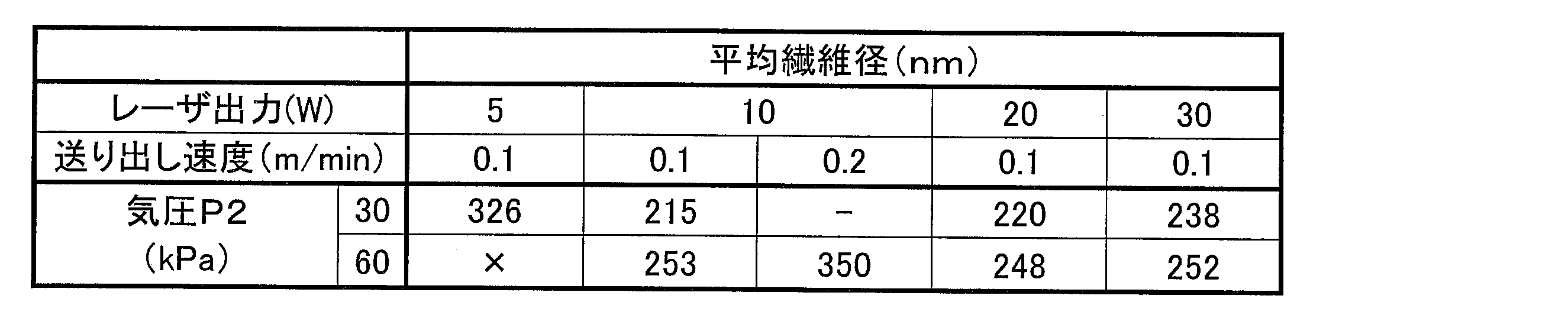
表6に示すように、レーザ出力が5W、送り出し速度が0.1mm、チャンバ内の気圧が60kPaの条件ではナノファイバを製造することができなかった。しかしながら、ナノファイバを製造することができなかった条件から、レーザ出力を10Wにまで高めた製造条件、及び、ナノファイバを製造することができなかった条件からチャンバ内の気圧を30kPaにまで低くした製造条件においては、好適にナノファイバを製造することができることを確認できた。
〔実施例7〕
ポリフッ化ビニリデンKF#1300(株式会社クレハ製)を用いて、溶融紡糸により未延伸フィラメント(直径200μm)を作製し、オリフィスの出口からレーザ光が照射される領域の中心点までの距離L、及び、チャンバ内の気圧P2を変化させて、ナノファイバを製造し、得られたナノファイバの平均繊維径を測定した。
ポリフッ化ビニリデンKF#1300(株式会社クレハ製)を用いて、溶融紡糸により未延伸フィラメント(直径200μm)を作製し、オリフィスの出口からレーザ光が照射される領域の中心点までの距離L、及び、チャンバ内の気圧P2を変化させて、ナノファイバを製造し、得られたナノファイバの平均繊維径を測定した。
ナノファイバの製造は、図1の(a)に示す製造装置を用いて行なった。オリフィス径を0.5mm、レーザ出力を10W、原フィラメントの送り出し速度を0.2m/minに設定した。なお、P1は大気圧である。距離L及びチャンバ内の気圧P2の条件及び、これらの条件において得られたナノファイバの平均繊維径を以下の表7に示す。

表7に示すように、距離Lを変化させても、好適にナノファイバを製造することができることを確認できた。
〔実施例8〕
ポリフッ化ビニリデンKF#1300(株式会社クレハ製)を用いて、溶融紡糸により未延伸フィラメント(直径200μm)を作製し、オリフィス径、及び、チャンバ内の気圧P2を変化させてナノファイバを製造し、得られたナノファイバの平均繊維径を測定した。
ポリフッ化ビニリデンKF#1300(株式会社クレハ製)を用いて、溶融紡糸により未延伸フィラメント(直径200μm)を作製し、オリフィス径、及び、チャンバ内の気圧P2を変化させてナノファイバを製造し、得られたナノファイバの平均繊維径を測定した。
ナノファイバの製造は、図1の(a)に示す製造装置を用いて行なった。レーザ出力を10W、距離Lを1.5mm、原フィラメントの送り出し速度を0.2m/minに設定した。なお、P1は大気圧である。オリフィス径、及びチャンバ内の気圧P2の条件、並びに、これらの条件において得られたナノファイバの平均繊維径を以下の表8に示す。
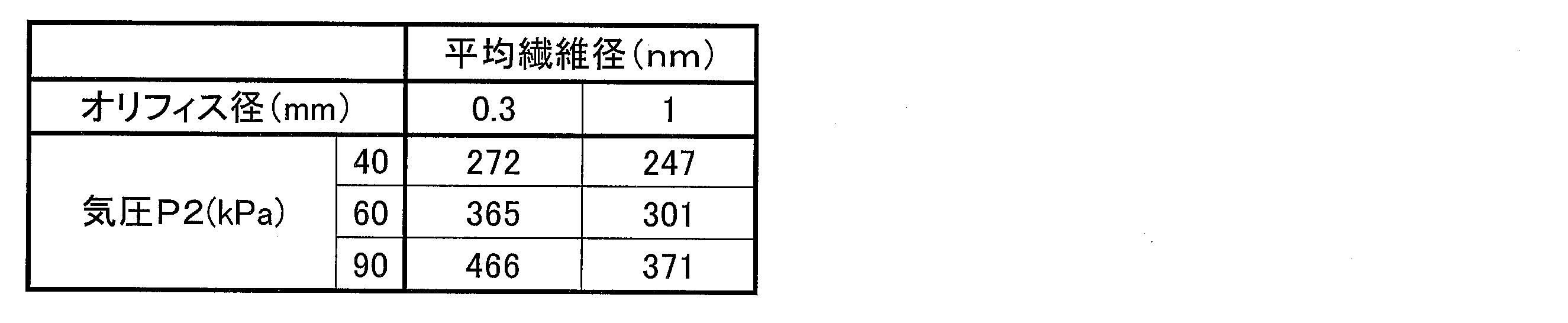
表8に示すように、未延伸フィラメントを原フィラメントとして用いる場合であっても、オリフィス径を大きくすることにより、平均繊維径を小さくすることができることを確認できた。
〔実施例9〕
ポリフッ化ビニリデンKF#1300(株式会社クレハ製)を用いて、溶融紡糸により未延伸フィラメント(直径200μm)を作製し、オリフィスの出口からレーザ光が照射される領域の中心点までの距離L、及び、チャンバ内の気圧P2を変化させて、ナノファイバを製造し、得られたナノファイバの平均繊維径を測定した。
ポリフッ化ビニリデンKF#1300(株式会社クレハ製)を用いて、溶融紡糸により未延伸フィラメント(直径200μm)を作製し、オリフィスの出口からレーザ光が照射される領域の中心点までの距離L、及び、チャンバ内の気圧P2を変化させて、ナノファイバを製造し、得られたナノファイバの平均繊維径を測定した。
ナノファイバの製造は、図1の(a)に示す製造装置を用いて行なった。オリフィス径を1.0mm、レーザ出力を10W、原フィラメントの送り出し速度を0.2m/minに設定した。なお、P1は大気圧である。距離L及びチャンバ内の気圧P2の条件、並びに、これらの条件において得られたナノファイバの平均繊維径を以下の表9に示す。

表9に示すように、距離Lを変化させても、好適にナノファイバを製造することができることを確認できた。
以上の通り、実施例1により、本発明に係るナノファイバの製造方法によれば、PVDFを用いてβ晶比率が75%以上のナノファイバを製造することができることを確認できた。また、実施例1~9により、平均繊維径が、700nm以下、特に、オリフィス径やレーザ出力などの各条件を調整することにより、400nm以下の平均繊維径のPVDFからなるナノファイバを製造することができることを確認できた。
本発明は、フッ化ビニリデン系樹脂のナノファイバの製造に利用することができる。
1 原フィラメント
2 ナノファイバ(極細ファイバ)
30 レーザ光(赤外線光束)
2 ナノファイバ(極細ファイバ)
30 レーザ光(赤外線光束)
Claims (7)
- フッ化ビニリデン系樹脂を含んでいる原フィラメントを当該原フィラメントの長さ方向に送り出しつつ赤外線光束により加熱し、加熱された当該原フィラメントを当該長さ方向に沿う気流により延伸することを特徴とするフッ化ビニリデン系樹脂の極細ファイバの製造方法。
- 上記気流は、上記原フィラメントの一方の端部が置かれる環境の気圧P1よりも、他方の端部が置かれる環境の気圧P2を低くすることにより生じさせることを特徴とする請求項1に記載の極細ファイバの製造方法。
- 上記原フィラメントは、未延伸のフィラメントであることを特徴とする請求項1又は2に記載の極細ファイバの製造方法。
- 上記フッ化ビニリデン系樹脂は、フッ化ビニリデンモノマーの単独重合体、又は、フッ化ビニリデンモノマーを50質量%以上含む共重合体であることを特徴とする請求項1~3の何れか1項に記載の極細ファイバの製造方法。
- 請求項1~4の何れか1項に記載の製造方法により製造することを特徴とする極細ファイバ。
- 極細化された上記フッ化ビニリデン系樹脂におけるβ晶の割合が、75%以上であることを特徴とする請求項5に記載のフッ化ビニリデン系樹脂の極細ファイバ。
- 極細化された上記フッ化ビニリデン系樹脂の平均繊維径が、400nm以下であることを特徴とする請求項5又は6に記載のフッ化ビニリデン系樹脂の極細ファイバ。
Applications Claiming Priority (2)
| Application Number | Priority Date | Filing Date | Title |
|---|---|---|---|
| JP2015-002689 | 2015-01-08 | ||
| JP2015002689A JP6497506B2 (ja) | 2015-01-08 | 2015-01-08 | フッ化ビニリデン系樹脂の極細ファイバの製造方法及び、フッ化ビニリデン系樹脂の極細ファイバ |
Publications (1)
| Publication Number | Publication Date |
|---|---|
| WO2016111228A1 true WO2016111228A1 (ja) | 2016-07-14 |
Family
ID=56355922
Family Applications (1)
| Application Number | Title | Priority Date | Filing Date |
|---|---|---|---|
| PCT/JP2015/086500 Ceased WO2016111228A1 (ja) | 2015-01-08 | 2015-12-28 | フッ化ビニリデン系樹脂の極細ファイバの製造方法及び、フッ化ビニリデン系樹脂の極細ファイバ |
Country Status (2)
| Country | Link |
|---|---|
| JP (1) | JP6497506B2 (ja) |
| WO (1) | WO2016111228A1 (ja) |
Citations (3)
| Publication number | Priority date | Publication date | Assignee | Title |
|---|---|---|---|---|
| JP2007056402A (ja) * | 2005-08-24 | 2007-03-08 | Kureha Gosen Kk | ポリフッ化ビニリデン系フィラメント、及びポリフッ化ビニリデン系フィラメントの水中での透明性を向上させる方法 |
| WO2008084797A1 (ja) * | 2007-01-09 | 2008-07-17 | University Of Yamanashi | 極細フィラメントの製造方法及び製造装置 |
| JP2012221600A (ja) * | 2011-04-04 | 2012-11-12 | Shinshu Univ | セパレーター、セパレーター製造装置及びセパレーター製造方法 |
-
2015
- 2015-01-08 JP JP2015002689A patent/JP6497506B2/ja not_active Expired - Fee Related
- 2015-12-28 WO PCT/JP2015/086500 patent/WO2016111228A1/ja not_active Ceased
Patent Citations (3)
| Publication number | Priority date | Publication date | Assignee | Title |
|---|---|---|---|---|
| JP2007056402A (ja) * | 2005-08-24 | 2007-03-08 | Kureha Gosen Kk | ポリフッ化ビニリデン系フィラメント、及びポリフッ化ビニリデン系フィラメントの水中での透明性を向上させる方法 |
| WO2008084797A1 (ja) * | 2007-01-09 | 2008-07-17 | University Of Yamanashi | 極細フィラメントの製造方法及び製造装置 |
| JP2012221600A (ja) * | 2011-04-04 | 2012-11-12 | Shinshu Univ | セパレーター、セパレーター製造装置及びセパレーター製造方法 |
Also Published As
| Publication number | Publication date |
|---|---|
| JP6497506B2 (ja) | 2019-04-10 |
| JP2016125184A (ja) | 2016-07-11 |
Similar Documents
| Publication | Publication Date | Title |
|---|---|---|
| US8057730B2 (en) | Microfilament manufacturing method and manufacturing apparatus therefor | |
| US10981095B2 (en) | Nonwoven fabric and air filter including same | |
| WO2004085723A1 (ja) | 延伸された芯鞘型フィラメント | |
| JP6337093B2 (ja) | 極細繊維の製造方法 | |
| JP2017185422A (ja) | デプスフィルター | |
| US10590565B2 (en) | Polymeric nanofibers and nanofibrous web | |
| JP5842216B2 (ja) | 極細フィラメントの多錘延伸装置 | |
| JP6810663B2 (ja) | 極細繊維の製造装置 | |
| JP6497506B2 (ja) | フッ化ビニリデン系樹脂の極細ファイバの製造方法及び、フッ化ビニリデン系樹脂の極細ファイバ | |
| WO2011105414A1 (ja) | Pfa多孔質シート | |
| CN105658857A (zh) | 熔融纺丝的聚丙烯精细级纳米纤维网 | |
| JP6562313B2 (ja) | 極細マルチフィラメント糸とその製造手段 | |
| JP2018202295A (ja) | エアフィルター及びその製造方法 | |
| JP6489297B2 (ja) | 3次元構造体の製造方法及び3次元構造体 | |
| JP6710038B2 (ja) | ナノファイバー不織布及びそれを用いた吸音材 | |
| JP6488431B2 (ja) | フッ化ビニリデン系樹脂ファイバー及びシート状構造体 | |
| JP6277465B2 (ja) | 高速巻取による耐熱性ナノフィラメントウェブヤーンの製造手段 | |
| JP2016211110A (ja) | Pet極細繊維の製造方法 | |
| JP2019018188A (ja) | エアフィルター、及びその製造方法 | |
| JP2010106408A (ja) | 耐熱性布帛 | |
| WO2025254024A1 (ja) | 積層不織布およびその製造方法ならびに滅菌包材 | |
| JP2019148018A (ja) | オリフィス構造体、ナノファイバー製造装置、及びナノファイバーの製造方法 |
Legal Events
| Date | Code | Title | Description |
|---|---|---|---|
| 121 | Ep: the epo has been informed by wipo that ep was designated in this application |
Ref document number: 15877100 Country of ref document: EP Kind code of ref document: A1 |
|
| NENP | Non-entry into the national phase |
Ref country code: DE |
|
| 122 | Ep: pct application non-entry in european phase |
Ref document number: 15877100 Country of ref document: EP Kind code of ref document: A1 |