WO2016110179A1 - Phase shifting device and electric tilt antenna - Google Patents
Phase shifting device and electric tilt antenna Download PDFInfo
- Publication number
- WO2016110179A1 WO2016110179A1 PCT/CN2015/098024 CN2015098024W WO2016110179A1 WO 2016110179 A1 WO2016110179 A1 WO 2016110179A1 CN 2015098024 W CN2015098024 W CN 2015098024W WO 2016110179 A1 WO2016110179 A1 WO 2016110179A1
- Authority
- WO
- WIPO (PCT)
- Prior art keywords
- phase shifting
- shifting device
- substrates
- phase
- substrate
- Prior art date
Links
Images


Classifications
-
- H—ELECTRICITY
- H01—ELECTRIC ELEMENTS
- H01Q—ANTENNAS, i.e. RADIO AERIALS
- H01Q3/00—Arrangements for changing or varying the orientation or the shape of the directional pattern of the waves radiated from an antenna or antenna system
- H01Q3/26—Arrangements for changing or varying the orientation or the shape of the directional pattern of the waves radiated from an antenna or antenna system varying the relative phase or relative amplitude of energisation between two or more active radiating elements; varying the distribution of energy across a radiating aperture
- H01Q3/30—Arrangements for changing or varying the orientation or the shape of the directional pattern of the waves radiated from an antenna or antenna system varying the relative phase or relative amplitude of energisation between two or more active radiating elements; varying the distribution of energy across a radiating aperture varying the relative phase between the radiating elements of an array
- H01Q3/32—Arrangements for changing or varying the orientation or the shape of the directional pattern of the waves radiated from an antenna or antenna system varying the relative phase or relative amplitude of energisation between two or more active radiating elements; varying the distribution of energy across a radiating aperture varying the relative phase between the radiating elements of an array by mechanical means
-
- H—ELECTRICITY
- H01—ELECTRIC ELEMENTS
- H01P—WAVEGUIDES; RESONATORS, LINES, OR OTHER DEVICES OF THE WAVEGUIDE TYPE
- H01P1/00—Auxiliary devices
- H01P1/18—Phase-shifters
-
- H—ELECTRICITY
- H01—ELECTRIC ELEMENTS
- H01P—WAVEGUIDES; RESONATORS, LINES, OR OTHER DEVICES OF THE WAVEGUIDE TYPE
- H01P1/00—Auxiliary devices
- H01P1/18—Phase-shifters
- H01P1/184—Strip line phase-shifters
-
- H—ELECTRICITY
- H01—ELECTRIC ELEMENTS
- H01Q—ANTENNAS, i.e. RADIO AERIALS
- H01Q1/00—Details of, or arrangements associated with, antennas
- H01Q1/48—Earthing means; Earth screens; Counterpoises
Landscapes
- Waveguide Switches, Polarizers, And Phase Shifters (AREA)
Abstract
The present invention provides a phase shifting device and an electric tilt antenna. The phase shifting device comprises: a grounding plate; two bottom substrates respectively arranged on both sides of the grounding plate and coupled to the grounding plate; two top substrates respectively arranged on both sides of the two bottom substrates, wherein each top substrate and each bottom substrate compose a phase shifting unit; a draw-bar coupled to the two top substrates and used for adjusting the relative sliding between the two top substrates and the two bottom substrates so as to adjust the phase of the output signal of each phase shifting unit at the same time. By means of the technical solution of the present invention, screws are not needed in course of assembling the phase shifting device, PIM performance of the phase shifting device is improved, and the friction is smaller, so that an ACU can drive the draw-bar at a low temperature. The phase shifting device, with few parts, low cost and connections by use of nonmetallic rivets, is very easy to assemble and rework.
Description
本发明概括而言涉及无线通信领域,更具体而言,涉及一种用于电调天线的移相装置。The present invention relates generally to the field of wireless communications and, more particularly, to a phase shifting apparatus for an electronically modulated antenna.
电调天线广泛地运用在无线传输中。除了辐射单元,反射板,移相网络(Phase Shifter network,PSN)是电调天线的一个重要组成部分。移相器主要用于电调天线中来调节馈电网络相位的变化,从而改变每一个或一组辐射单元的相位,达到改变垂直面波束倾角或水平面波束角度的目的。特别地,在当前的移相网络PSN中,往往采用空气带状线来传输信号,同时采用在带状线特定位置下方放置可移动介质的方式实现相位的改变。Electrically modulated antennas are widely used in wireless transmission. In addition to the radiating element, the reflector, the Phase Shifter network (PSN) is an important part of the ESC antenna. The phase shifter is mainly used in the electric adjustment antenna to adjust the phase change of the feed network, thereby changing the phase of each or a group of radiation units to achieve the purpose of changing the vertical beam angle or the horizontal beam angle. In particular, in the current phase shifting network PSN, an air strip line is often used to transmit signals, and a phase change is achieved by placing a movable medium below a specific position of the strip line.
带状线往往有如下缺点:首先,带状线很长且薄,因此很容易变形,并且有时在两个带状线之间需要进行焊接;其次,PSN中的有一部分通过螺丝进行固定,而金属的螺丝会影响PSN的无源互调(PIM)的性能;另外,目前的构成PSN的移相单元结构很复杂,难以组装和返工,而且PSN有时还可以包括更多的移相单元,当PSN用于环境测试时,天线控制单元(Antenna Control Unit,ACU)不能驱动移相装置,从而给PSN使用造成不便,限制了PSN的使用。Stripline tends to have the following disadvantages: First, the stripline is long and thin, so it is easily deformed, and sometimes welding is required between the two striplines; secondly, a part of the PSN is fixed by screws, and Metal screws can affect the performance of PSN passive intermodulation (PIM); in addition, the current phase shifting unit structure that constitutes PSN is complex, difficult to assemble and rework, and PSN can sometimes include more phase shifting units. When the PSN is used for environmental testing, the Antenna Control Unit (ACU) cannot drive the phase shifting device, which causes inconvenience to the use of the PSN and limits the use of the PSN.
因此,亟需一种具有良好的PIM性能且易于组装的移相装置。Therefore, there is a need for a phase shifting device that has good PIM performance and is easy to assemble.
发明内容Summary of the invention
针对以上问题,本发明对提出了一种具有良好的PIM性能且易于组装的移相装置以及采用该移相装置的电调天线。In view of the above problems, the present invention proposes a phase shifting device having good PIM performance and being easy to assemble, and an electric adjustable antenna using the phase shifting device.
本发明一方面提出了一种移相装置,其包括:接地板;至少两个底部基板,其分别位于所述接地板的两侧,并且耦接至所述接地板;至少两个顶部基板,其分别位于所述两个底部基板的两侧,每个所述
顶部基板与每个所述底部基板构成一个移相单元;拉杆,其耦接至所述两个顶部基板,用于调节所述至少两个顶部基板与所述至两个底部基板之间的相对滑动,从而同时调整每个所述移相单元输出信号的相位。One aspect of the present invention provides a phase shifting device including: a ground plate; at least two bottom substrates respectively located on both sides of the ground plate and coupled to the ground plate; at least two top substrates, They are respectively located on both sides of the two bottom substrates, each of which is
a top substrate and each of the bottom substrates form a phase shifting unit; a tie rod coupled to the two top substrates for adjusting a relative relationship between the at least two top substrates and the two bottom substrates Sliding to simultaneously adjust the phase of each of the phase shifting unit output signals.
因此,上述实施方式实现了具有至少两个移相单元的移相装置,并且能够同时以相反的相位变化趋势调整两个移相单元进行移相,实现了以较小的滑动行程实现较大的相位差,减小了移相装置的体积。Therefore, the above embodiment realizes a phase shifting device having at least two phase shifting units, and can simultaneously adjust two phase shifting units for phase shifting with opposite phase change trends, achieving a larger sliding stroke with a smaller sliding stroke. The phase difference reduces the volume of the phase shifting device.
优选的,所述底部基板的、面向所述顶部基板的侧面设置有至少一根信号输入线和至少一根移相信号输出线。Preferably, at least one signal input line and at least one phase shift signal output line of the bottom substrate facing the top substrate are disposed.
优先的,所述顶部基板的、面向所述底部基板的侧面设置有至少一个U型线,所述至少一个U型线耦合至所述至少一根信号输入线和所述至少一根移相信号输出线。Preferentially, at least one U-shaped line is disposed on a side of the top substrate facing the bottom substrate, the at least one U-shaped line being coupled to the at least one signal input line and the at least one phase shifting signal Output line.
如此,每个移相单元中将包含至少一个移相器,并且每个移相器与U型线一一对应。As such, each phase shifting unit will include at least one phase shifter, and each phase shifter has a one-to-one correspondence with the U-shaped line.
优选的,所述移相装置还包括:固定部件,其用于将所述两个顶部基板相互固定,并且所述拉杆通过所述固定部件耦接至所述两个顶部基板。Preferably, the phase shifting device further includes: a fixing member for fixing the two top substrates to each other, and the tie rod is coupled to the two top substrates by the fixing member.
优选的,所述固定部件包括:两个能够相互扣紧的第一固件和第二固件,当所述第一、第二固件扣紧时,所述顶部基板与所述底部基板贴合。Preferably, the fixing component comprises: two first fasteners and a second firmware that can be fastened to each other, and the top substrate is adhered to the bottom substrate when the first and second fasteners are fastened.
优选的,所述第一固件上设置有至少一个铆钉和至少一个凹槽,所述第二固件上对应地设置有至少一个铆钉和至少一个凹槽,从而所述第一固件和第二固件之间能够通过铆钉和凹槽的相匹配以形成固定连接。Preferably, the first firmware is provided with at least one rivet and at least one groove, and the second firmware is correspondingly provided with at least one rivet and at least one groove, so that the first firmware and the second firmware The rivets and grooves can be matched to form a fixed connection.
如此,移相装置在组装时并不需要使用螺丝,提供了使用多种材料的可能性。As such, the phase shifting device does not require the use of screws when assembled, providing the possibility of using a variety of materials.
优选的,所述顶部基板上设置有至少两个通孔,以供所述第一、第二固件上的铆钉穿过;以及所述底部基板上设置有至少一个长孔,用于提供所述第一、第二固件上的铆钉的运动空间。
Preferably, the top substrate is provided with at least two through holes for the rivets on the first and second firmware to pass through; and the bottom substrate is provided with at least one long hole for providing the The movement space of the rivet on the first and second firmware.
在顶部基板运动时,其摩擦力很小,使得ACU能够在低温下驱动拉杆。When the top substrate is moving, its friction is small, allowing the ACU to drive the lever at low temperatures.
优选的,移相装置还包括:板接铆钉,用于通过设置于所述两个底部基板上的通孔和设置于所述接地板上的通孔将所述两个底部基板与所述接地板相固定。Preferably, the phase shifting device further comprises: a plate rivet for connecting the two bottom substrates with the through holes provided on the two bottom substrates and the through holes provided on the ground plate The floor is fixed.
优选的,所述底部基板与所述顶部基板上除了焊接的位置,其它位置覆有绝缘层。Preferably, the bottom substrate and the top substrate are covered with an insulating layer at other positions except for soldering.
优选的,所述底部基板的、面向所述顶部基板的侧面设置有一根信号输入线和三根移相信号输出线,其中,所述三根移相信号输出线中的两根通过外部导体相连接。Preferably, a side of the bottom substrate facing the top substrate is provided with a signal input line and three phase shifting signal output lines, wherein two of the three phase shifting signal output lines are connected by an external conductor.
优选的,所述固定部件和/或所述板接铆钉由非金属材料制成。Preferably, the fixing member and/or the plate rivet are made of a non-metallic material.
如此,移相装置并未采用或相对较少地使用金属元件,从而提升了移相装置PIM性能。As such, the phase shifting device does not employ or relatively less use of metal components, thereby improving the PIM performance of the phase shifting device.
本发明另外一方面提出了一种电调天线,其包括:移相装置;天线控制单元,其耦接至所述拉杆,用于驱动所述拉杆,进而使得所述两个顶部基板能够同时地相对所述两个底部基板滑动。Another aspect of the present invention provides an electrical adjustment antenna including: a phase shifting device; an antenna control unit coupled to the pull rod for driving the pull rod, thereby enabling the two top substrates to be simultaneously Sliding relative to the two bottom substrates.
通过采用本发明中的技术方案,移相装置在组装时并不需要使用螺丝,避免或相对较少地采用金属元件,从而提升了移相装置的PIM性能。另外,在顶部基板运动时,其摩擦力很小,使得ACU能够在低温下驱动拉杆,并且移相装置的零件很少,成本较低,使用非金属的铆钉进行连接,十分容易组装和返工。By adopting the technical solution of the present invention, the phase shifting device does not need to use screws when assembling, and the metal component is avoided or relatively less, thereby improving the PIM performance of the phase shifting device. In addition, when the top substrate is moved, its friction is small, enabling the ACU to drive the drawbar at low temperatures, and the phase shifting device has few parts and low cost, and is connected by non-metallic rivets, which is easy to assemble and rework.
通过参考下列附图所给出的本发明的具体实施方式的描述之后,将更好地理解本发明,并且本发明的其他目的、细节、特点和优点将变得更加显而易见。在附图中:The invention will be better understood, and the other objects, details, features and advantages of the invention will become more apparent from the Detailed Description. In the drawing:
图1为依据本发明实施例的移相装置爆炸图;1 is an exploded view of a phase shifting device in accordance with an embodiment of the present invention;
图2为依据本发明实施例的底部基板和顶部基板的简略示意图;2 is a schematic diagram of a base substrate and a top substrate according to an embodiment of the invention;
图3为依据本发明实施例的天线的移相信号示意图;
3 is a schematic diagram of a phase shifting signal of an antenna according to an embodiment of the present invention;
图4a为依据本发明实施例的移相装置组装后滑动之前的示意图;4a is a schematic view of a phase shifting device before being assembled and slid according to an embodiment of the present invention;
图4b为依据本发明实施例的移相装置组装后滑动之后的示意图;4b is a schematic view of the phase shifting device after being assembled and slid according to an embodiment of the present invention;
图5a为依据本发明实施例的移相装置在1900MHz载频下的无源互调仿真图;5a is a simulation diagram of passive intermodulation of a phase shifting device at a carrier frequency of 1900 MHz according to an embodiment of the present invention;
图5b为依据本发明实施例的移相装置在2600MHz载频下的无源互调仿真图。FIG. 5b is a simulation diagram of passive intermodulation of a phase shifting device at a carrier frequency of 2600 MHz according to an embodiment of the invention.
下面将参照附图更详细地描述本公开的优选实施方式。虽然附图中显示了本公开的优选实施方式,然而应该理解,可以以各种形式实现本公开而不应被这里阐述的实施方式所限制。相反,提供这些实施方式是为了使本公开更加透彻和完整,并且能够将本公开的范围完整的传达给本领域的技术人员。Preferred embodiments of the present disclosure will be described in more detail below with reference to the accompanying drawings. While the preferred embodiment of the present invention has been shown in the drawings, it is understood that Rather, these embodiments are provided so that this disclosure will be thorough and complete.
图1为依据本发明实施例的移相装置爆炸图。1 is an exploded view of a phase shifting device in accordance with an embodiment of the present invention.
由图1可知,移相装置包括:拉杆1、两个固定部件2、两个顶部基板3、两个底部基板5以及接地板6,其中,顶部基板3、底部基板5构成了移相单元,也就是说移相装置包含了分布于接地板上下两侧的两个移相单元,而每个移相单元可以包含至少一个移相器。As shown in FIG. 1 , the phase shifting device includes: a tie rod 1 , two fixing members 2 , two top substrates 3 , two bottom substrates 5 , and a ground plate 6 , wherein the top substrate 3 and the bottom substrate 5 constitute a phase shifting unit. That is to say, the phase shifting device comprises two phase shifting units distributed on the lower two sides of the grounding plate, and each phase shifting unit may comprise at least one phase shifter.
具体地,两个底部基板5分别位于接地板6的两侧,并且电气耦接至接地板6,两个底部基板5还包括信号输入线与移相信号输出线(图中未示出);两个顶部基板3分别位于两个底部基板5的两侧,即顶部基板3、底部基板5和接地板6依次设置;拉杆1用于调节顶部基板与两个底部基板之间的相对滑动,从而能够同时并且以相反的相位变化趋势调整每个移相单元输出信号的相位。Specifically, the two bottom substrates 5 are respectively located at two sides of the grounding plate 6, and are electrically coupled to the grounding plate 6. The two bottom substrates 5 further include a signal input line and a phase shifting signal output line (not shown); Two top substrates 3 are respectively disposed on two sides of the two bottom substrates 5, that is, the top substrate 3, the bottom substrate 5 and the ground plate 6 are sequentially disposed; the tie rod 1 is used for adjusting the relative sliding between the top substrate and the two bottom substrates, thereby The phase of each phase shifting unit output signal can be adjusted simultaneously and with opposite phase changes.
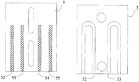
图2为依据本发明实施例的底部基板和顶部基板的简略示意图。2 is a schematic diagram of a base substrate and a top substrate in accordance with an embodiment of the present invention.
底部基板5面向顶部基板3的侧面设置至少一根信号输入线和至少一根移相信号输出线,譬如,分别为一根信号输入线52和三根移相信号输出线53-55。顶部基板面向底部基板的侧面设置有至少一个U型线,譬如两个U型线32、33,当底部基板和顶部基板靠近甚至
贴合时,即使其表面覆盖有绝缘层,两个基板之间的信号也能够通过耦合方式进行传输。因此,图中的两个U型线实现了两个移相器,也就是说,移相单元包含了两个移相器。可以理解的是,图2并未示出底部基板与顶部基板的所有细节,仅仅示出了与信号耦合相关的部分。The bottom substrate 5 faces at the side of the top substrate 3 with at least one signal input line and at least one phase shift signal output line, for example, one signal input line 52 and three phase shift signal output lines 53-55, respectively. The side of the top substrate facing the bottom substrate is provided with at least one U-shaped wire, such as two U-shaped wires 32, 33, when the bottom substrate and the top substrate are close or even
When laminated, even if the surface is covered with an insulating layer, signals between the two substrates can be transmitted by coupling. Therefore, the two U-shaped lines in the figure implement two phase shifters, that is, the phase shifting unit contains two phase shifters. It will be understood that Figure 2 does not show all the details of the base substrate and the top substrate, only the portions associated with signal coupling are shown.
优选的,底部基板5与顶部基板3上除了焊接的位置,其它位置均覆有绝缘层,譬如液态光致阻焊剂(绿油)。Preferably, the bottom substrate 5 and the top substrate 3 are covered with an insulating layer, such as a liquid photo solder resist (green oil), except for soldering.
请仍然参阅图1,在本实施例中,固定部件2用于将位于接地板6两侧的两个顶部基板3相互固定。固定部件2还耦接至拉杆1,从而当拉杆1进行左右运动时,其将带动分布在接地板6两侧的顶部基板3以同样的方向运动。Still referring to FIG. 1, in the present embodiment, the fixing member 2 is for fixing the two top substrates 3 located on both sides of the ground plate 6 to each other. The fixing member 2 is also coupled to the pull rod 1 so that when the pull rod 1 is moved left and right, it will drive the top substrate 3 distributed on both sides of the ground plate 6 to move in the same direction.
优选的,固定部件2包括两个能够相互扣紧的第一固件和第二固件,当第一、第二固件扣紧时,顶部基板与底部基板贴合或是之间留有较小的间隙。具体地,第一固件上设置有至少一个铆钉21和至少一个凹槽,第二固件上对应地设置有至少一个铆钉21和至少一个凹槽,从而第一固件和第二固件之间能够通过铆钉和凹槽的相匹配以形成固定连接。相应地,顶部基板3上设置有至少两个通孔31,以供所述第一、第二固件上的铆钉21穿过,从而进行固定。在底部基板上还设置有至少一个长孔,譬如两个长孔51,用于提供第一、第二固件上的铆钉21的运动空间。也就是说,第一固件上的铆钉21将依次穿过通孔31、长孔51和长孔61然后再穿过另一侧的长孔51、通孔31,最终与第二固件上的凹槽相插合,以形成固定连接。当拉杆1进行左右运动时,两侧的顶部基板3以同样的方向运动,并且由于铆钉处于长孔51和61中,因此,其运动的摩擦力很小。Preferably, the fixing component 2 comprises two first firmware and a second firmware that can be fastened to each other. When the first and second fasteners are fastened, the top substrate and the bottom substrate are bonded or have a small gap therebetween. . Specifically, the first firmware is provided with at least one rivet 21 and at least one groove, and the second firmware is correspondingly provided with at least one rivet 21 and at least one groove, so that the rivet can be passed between the first firmware and the second firmware. Matching the grooves to form a fixed connection. Correspondingly, at least two through holes 31 are provided in the top substrate 3 for the rivets 21 on the first and second firmware to pass through to be fixed. Further, at least one long hole, such as two long holes 51, is provided on the bottom substrate for providing a movement space of the rivet 21 on the first and second firmware. That is, the rivets 21 on the first firmware will sequentially pass through the through holes 31, the long holes 51 and the long holes 61 and then pass through the long holes 51, the through holes 31 on the other side, and finally the concave on the second firmware. The slots are inserted to form a fixed connection. When the tie rod 1 is moved left and right, the top substrates 3 on both sides are moved in the same direction, and since the rivets are in the long holes 51 and 61, the frictional force of the movement is small.
为了使得底部基板5与接地板6之间保持固定连接且不发生相对位移,因此,移相装置还包括板接铆钉7。该板接铆钉7通过设置于两个底部基板5上的通孔56和设置于接地板上的通孔62将两个底部基板与接地板相互固定。In order to maintain a fixed connection between the base substrate 5 and the ground plate 6 without relative displacement, the phase shifting device further includes a plate rivet 7. The board rivet 7 fixes the two base substrates and the ground plate to each other through a through hole 56 provided in the two bottom substrates 5 and a through hole 62 provided in the ground plate.
图3为依据本发明实施例的天线的移相信号示意图。
3 is a schematic diagram of a phase shifting signal of an antenna according to an embodiment of the invention.
在图2中,C0为输入电缆,C1、C2为功率分配器至移相器之间的电缆,C3-C4、C6-C7为移相器至功率分配器的电缆,C5为两个功率分配器之间的电缆,C8-C17为所需的移相信号。本实施例中的移相装置则是虚线框中的部分,因此,前述的设置在两个底部基板上的信号输入线52对应着C1和C2,同样,设置在两个底部基板上的移相输出线53-55则对应着C3-C4和C6-C7。In Figure 2, C0 is the input cable, C1, C2 are the cables between the power splitter and the phase shifter, C3-C4, C6-C7 are the cables from the phase shifter to the power splitter, and C5 is the two power distributions. The cable between the devices, C8-C17, is the desired phase shift signal. The phase shifting device in this embodiment is a portion in the dotted line frame. Therefore, the aforementioned signal input line 52 disposed on the two bottom substrates corresponds to C1 and C2, and similarly, the phase shifting on the two bottom substrates is provided. Output lines 53-55 correspond to C3-C4 and C6-C7.
当该移相装置使用在天线中时,需要向其输入信号和接收其移相后的信号,因此,如图1所示,电缆8-11分别通过耦接块4耦接至底部基板5上设置的一根信号输入线52和三根移相信号输出线53-55。对应的,电缆8、12-14分别耦接至另一底部基板5上的信号输入线和三根移相信号输出线。When the phase shifting device is used in the antenna, it is required to input a signal thereto and receive the phase-shifted signal. Therefore, as shown in FIG. 1, the cables 8-11 are respectively coupled to the base substrate 5 through the coupling block 4. A signal input line 52 and three phase shift signal output lines 53-55 are provided. Correspondingly, the cables 8, 12-14 are respectively coupled to the signal input line and the three phase shift signal output lines on the other bottom substrate 5.
另外,将电缆9、10相接,电缆12、13相接,从而分别形成对应的C4和C6。In addition, the cables 9, 10 are connected, and the cables 12, 13 are connected to form corresponding C4 and C6, respectively.
当拉杆1驱动上下两块顶部基板在同一方向上运动时,显然信号在上下两块顶部基板和两块底部基板之间的传输路径产生了变化,即一个变大一个变小,从而使得C3与C7之间的相位差变大,因此,本实施例通过上下两层基板的设置,使得顶部基板仅需要移动很小的距离,便可以达到改变相位差的效果,因此,移相装置可以做得相对较小,以节省成本。When the pull rod 1 drives the upper and lower top substrates to move in the same direction, it is obvious that the transmission path between the upper and lower two substrates and the two bottom substrates changes, that is, one becomes larger and smaller, so that C3 and The phase difference between C7 becomes large. Therefore, in this embodiment, the arrangement of the upper and lower substrates is such that the top substrate only needs to be moved by a small distance, so that the effect of changing the phase difference can be achieved. Therefore, the phase shifting device can be made. Relatively small to save costs.
优选的,上述的固定部件2和/或板接铆钉7由非金属材料制成,如此可以提升移相装置的PIM性能。这里的非金属材料可以是塑料、橡胶等等。Preferably, the fixing member 2 and/or the plate rivet 7 described above are made of a non-metallic material, which can improve the PIM performance of the phase shifting device. The non-metallic materials herein may be plastics, rubber, and the like.
图4a示出了依据本发明实施例的移相装置组装后滑动前的状态示意图,图4b示出了依据本发明实施例的移相装置组装后滑动后的状态示意图。4a is a schematic view showing a state before the phase shifting device is assembled and slid according to an embodiment of the present invention, and FIG. 4b is a schematic view showing a state after the phase shifting device is assembled and slid according to an embodiment of the present invention.
显然,通过拉杆1带动顶部基板3的运动,可以明显改变信号的传输路径长度,从而可以通过仅仅滑动较小的距离,便可以在移相装置左右两边的实现较大的相位差。Obviously, by moving the top substrate 3 by the pull rod 1, the length of the signal transmission path can be significantly changed, so that a large phase difference can be realized on both the left and right sides of the phase shifting device by sliding only a small distance.
本发明还提出了一种电调天线,包括:该天线包括前述的移相装
置以及ACU,其中,ACU耦接至拉杆1,用于驱动拉杆1,进而使得两个顶部基板能够同时地相对两个底部基板滑动,从而能够以较小的滑动行程实现较大的相位差。The invention also proposes an electrical adjustment antenna, comprising: the antenna comprises the phase shifting device described above
And the ACU, wherein the ACU is coupled to the pull rod 1 for driving the pull rod 1, thereby enabling the two top substrates to slide simultaneously with respect to the two bottom substrates, so that a large phase difference can be realized with a small sliding stroke.
图5a为依据本发明实施例的移相装置在1900MHz载频下的无源互调仿真图,图5b为依据本发明实施例的移相装置在2600MHz载频下的无源互调仿真图。5a is a simulation diagram of passive intermodulation of a phase shifting device at a carrier frequency of 1900 MHz according to an embodiment of the invention, and FIG. 5b is a simulation diagram of passive intermodulation of a phase shifting device at a carrier frequency of 2600 MHz according to an embodiment of the invention.
因为无源器件的互调失真与载频功率的大小有关,因此采用相对值表达方式更能体现移相装置的无源互调的稳定性,即无源互调值与载频的比值,单位为dBc。Because the intermodulation distortion of the passive device is related to the magnitude of the carrier frequency power, the relative value expression can better reflect the stability of the passive intermodulation of the phase shifting device, that is, the ratio of the passive intermodulation value to the carrier frequency. For dBc.
在发射功率为20W的条件下,由图5a可以观察到,移相装置在1900MHz载频下,无源互调最坏的情形为-173dBc;由图5b可以观察到,在2600MHz载频下,移相装置的无源互调最坏的情形为-172dBc。Under the condition of 20W transmission power, it can be observed from Fig. 5a that the worst case of passive intermodulation is 173dBc at 1900MHz carrier frequency; as shown in Fig. 5b, at 2600MHz carrier frequency, The worst case of passive intermodulation of the phase shifting device is -172dBc.
因此,本发明的移相装置具有稳定的PIM性能。Therefore, the phase shifting device of the present invention has stable PIM performance.
综上所述,本发明的移相装置包含了两个移相单元,并且能够同时以相反的相位变化趋势调整两个移相单元进行移相,实现了以较小的滑动行程实现较大的相位差,减小了移相装置的体积。另外,移相装置在组装时并不需要使用螺丝,避免了使用金属元件影响移相装置的PIM性能,并且在顶部基板运动时,其摩擦力很小,使得ACU能够在低温下驱动拉杆。上述的移相装置的零件很少,成本较低,并且使用非金属的铆钉进行连接,十分容易组装和返工。In summary, the phase shifting device of the present invention comprises two phase shifting units, and can simultaneously adjust two phase shifting units for phase shifting with opposite phase change trends, thereby realizing a larger sliding stroke. The phase difference reduces the volume of the phase shifting device. In addition, the phase shifting device does not require the use of screws during assembly, which avoids the use of metal components to affect the PIM performance of the phase shifting device, and the friction of the top substrate is small, allowing the ACU to drive the drawbar at low temperatures. The phase shifting device described above has few parts, is relatively low cost, and is connected using non-metallic rivets, which is very easy to assemble and rework.
本领域技术人员能够理解的是,上述的状态仅仅用于示例,并非用于限定本发明的应用范围。本领域技术人员可以针对每种特定应用,以变通的方式实现所描述的功能,但是,这种实现决策不应解释为背离本发明的保护范围。
It is to be understood by those skilled in the art that the above-described state is for illustrative purposes only and is not intended to limit the scope of application of the present invention. A person skilled in the art can implement the described functions in a modified manner for each specific application, but such implementation decisions should not be construed as departing from the scope of the invention.
Claims (12)
- 一种移相装置,其特征在于,包括:A phase shifting device, comprising:接地板;Grounding plate至少两个底部基板,其分别位于所述接地板的两侧,并且耦接至所述接地板;At least two bottom substrates respectively located on both sides of the ground plate and coupled to the ground plate;至少两个顶部基板,其分别位于所述两个底部基板的两侧,每个所述顶部基板与每个所述底部基板构成一个移相单元;At least two top substrates respectively located on opposite sides of the two bottom substrates, each of the top substrates and each of the bottom substrates forming a phase shifting unit;拉杆,其耦接至所述两个顶部基板,用于调节所述两个顶部基板与所述两个底部基板之间的相对滑动,从而同时调整每个所述移相单元输出信号的相位。A tie rod coupled to the two top substrates for adjusting relative sliding between the two top substrates and the two bottom substrates to simultaneously adjust a phase of each of the phase shifting unit output signals.
- 如权利要求1所述的移相装置,其特征在于,The phase shifting device according to claim 1, wherein所述底部基板上面向所述顶部基板的侧面设置有至少一根信号输入线和至少一根移相信号输出线。At least one signal input line and at least one phase shift signal output line are disposed on a side of the bottom substrate facing the top substrate.
- 如权利要求2所述的移相装置,其特征在于,The phase shifting device according to claim 2, wherein所述顶部基板的、面向所述底部基板的侧面设置有至少一个U型线,所述至少一个U型线耦合至所述至少一根信号输入线和所述至少一根移相信号输出线。At least one U-shaped line is disposed on a side of the top substrate facing the bottom substrate, the at least one U-shaped line being coupled to the at least one signal input line and the at least one phase-shifted signal output line.
- 如权利要求1所述的移相装置,其特征在于,所述移相装置还包括:The phase shifting device of claim 1 wherein said phase shifting device further comprises:固定部件,其用于将所述两个顶部基板相互固定,并且所述拉杆通过所述固定部件耦接至所述两个顶部基板。a fixing member for fixing the two top substrates to each other, and the tie rod is coupled to the two top substrates by the fixing member.
- 如权利要求4所述的移相装置,其特征在于,所述固定部件包括:The phase shifting device according to claim 4, wherein said fixing member comprises:两个能够相互扣紧的第一固件和第二固件,当所述第一、第二固件扣紧时,所述顶部基板与所述底部基板贴合。Two first firmware and a second firmware that can be fastened to each other, and the top substrate is attached to the bottom substrate when the first and second firmware are fastened.
- 如权利要求5所述的移相装置,其特征在于,The phase shifting device according to claim 5, wherein所述第一固件上设置有至少一个铆钉和至少一个凹槽,所述第 二固件上对应地设置有至少一个铆钉和至少一个凹槽,从而所述第一固件和第二固件之间能够通过铆钉和凹槽的相匹配以形成固定连接。The first firmware is provided with at least one rivet and at least one groove, the first The second firmware is correspondingly provided with at least one rivet and at least one groove, so that the first and second firmware can be matched by rivets and grooves to form a fixed connection.
- 如权利要求6所述的移相装置,其特征在于,A phase shifting device according to claim 6 wherein:所述顶部基板上设置有至少两个通孔,以供所述第一、第二固件上的铆钉穿过;以及Providing at least two through holes on the top substrate for rivets on the first and second firmware; and所述底部基板上设置有至少一个长孔,用于提供所述第一、第二固件上的铆钉的运动空间。The bottom substrate is provided with at least one long hole for providing a movement space of the rivet on the first and second firmware.
- 如权利要求1所述的移相装置,其特征在于,还包括:The phase shifting device of claim 1 further comprising:板接铆钉,用于通过设置于所述两个底部基板上的通孔和设置于所述接地板上的通孔将所述两个底部基板与所述接地板相固定。a plate rivet for fixing the two bottom substrates to the ground plate through through holes provided on the two bottom substrates and through holes provided on the ground plate.
- 如权利要求1所述的移相装置,其特征在于,The phase shifting device according to claim 1, wherein所述底部基板与所述顶部基板上除了焊接的位置,其它位置覆有绝缘层。The bottom substrate and the top substrate are covered with an insulating layer at other positions except for soldering.
- 如权利要求1所述的移相装置,其特征在于,The phase shifting device according to claim 1, wherein所述底部基板的、面向所述顶部基板的侧面设置有一根信号输入线和三根移相信号输出线,其中,所述三根移相信号输出线中的两根通过外部导体相连接。A signal input line and three phase shift signal output lines are disposed on a side of the bottom substrate facing the top substrate, wherein two of the three phase shift signal output lines are connected by an external conductor.
- 如权利要求1-10任一项所述的移相装置,其特征在于,A phase shifting device according to any one of claims 1 to 10, wherein所述固定部件和/或所述板接铆钉由非金属材料制成。The fixing member and/or the plate rivet are made of a non-metallic material.
- 一种电调天线,其特征在于,包括:An electric adjustable antenna, comprising:如权利要求1所述的移相装置;The phase shifting device of claim 1;天线控制单元,其耦接至所述拉杆,用于驱动所述拉杆,进而使得所述两个顶部基板能够同时地相对所述两个底部基板滑动。 An antenna control unit coupled to the pull rod for driving the pull rod to enable the two top substrates to slide simultaneously relative to the two bottom substrates.
Priority Applications (2)
| Application Number | Priority Date | Filing Date | Title |
|---|---|---|---|
| US15/541,539 US10411346B2 (en) | 2015-01-05 | 2015-12-21 | Phase shifting apparatus and electrically adjustable antenna |
| EP15876679.0A EP3244479B1 (en) | 2015-01-05 | 2015-12-21 | Phase shifting device and electric tilt antenna |
Applications Claiming Priority (2)
| Application Number | Priority Date | Filing Date | Title |
|---|---|---|---|
| CN201510003349.5 | 2015-01-05 | ||
| CN201510003349.5A CN105826684B (en) | 2015-01-05 | 2015-01-05 | Phase shifting equipment and electrical tilt antenna |
Publications (1)
| Publication Number | Publication Date |
|---|---|
| WO2016110179A1 true WO2016110179A1 (en) | 2016-07-14 |
Family
ID=56355498
Family Applications (1)
| Application Number | Title | Priority Date | Filing Date |
|---|---|---|---|
| PCT/CN2015/098024 WO2016110179A1 (en) | 2015-01-05 | 2015-12-21 | Phase shifting device and electric tilt antenna |
Country Status (4)
| Country | Link |
|---|---|
| US (1) | US10411346B2 (en) |
| EP (1) | EP3244479B1 (en) |
| CN (1) | CN105826684B (en) |
| WO (1) | WO2016110179A1 (en) |
Cited By (1)
| Publication number | Priority date | Publication date | Assignee | Title |
|---|---|---|---|---|
| CN109768391A (en) * | 2018-12-29 | 2019-05-17 | 京信通信技术(广州)有限公司 | Antenna, the display system of antenna lower decline angle and its transmission mechanism |
Families Citing this family (6)
| Publication number | Priority date | Publication date | Assignee | Title |
|---|---|---|---|---|
| CN108260276A (en) * | 2016-12-29 | 2018-07-06 | 安弗施无线射频系统(上海)有限公司 | The standing-wave ratio modulated structure and method of a kind of printed circuit board |
| US11502407B2 (en) | 2018-07-12 | 2022-11-15 | Commscope Technologies Llc | Remote electronic tilt base station antennas having adjustable ret linkages |
| CN109802234B (en) * | 2019-01-30 | 2023-09-29 | 京信通信技术(广州)有限公司 | Base station antenna and phase-shift feed device |
| WO2021056554A1 (en) * | 2019-09-29 | 2021-04-01 | 华为技术有限公司 | Adjusting apparatus, multiband antenna, and base station |
| CN114447561A (en) * | 2020-11-05 | 2022-05-06 | 康普技术有限责任公司 | Support device for phase shifter of base station antenna |
| US11942682B2 (en) | 2021-04-21 | 2024-03-26 | Skyworks Solutions, Inc. | Electrically adjustable stencil for controlling antenna pattern for beamforming |
Citations (5)
| Publication number | Priority date | Publication date | Assignee | Title |
|---|---|---|---|---|
| EP0984509B1 (en) * | 1998-09-04 | 2004-05-19 | Agere Systems Optoelectronics Guardian Corporation | Reflection mode phase shifter |
| CN102544733A (en) * | 2012-01-31 | 2012-07-04 | 广东博纬通信科技有限公司 | Phase position continuous linear-variable phase shifter for base station electrically controlled antenna |
| CN202423518U (en) * | 2011-12-30 | 2012-09-05 | 东莞市晖速天线技术有限公司 | Phase shifter capable of improving phase shifting quantity and integration level and base station antenna with same |
| CN104051823A (en) * | 2014-06-06 | 2014-09-17 | 摩比天线技术(深圳)有限公司 | Phase shifter |
| CN204424453U (en) * | 2015-01-05 | 2015-06-24 | 安弗施无线射频系统(上海)有限公司 | Phase shifting equipment and electrical tilt antenna |
Family Cites Families (15)
| Publication number | Priority date | Publication date | Assignee | Title |
|---|---|---|---|---|
| US7274331B2 (en) * | 2001-12-03 | 2007-09-25 | Huber + Suhner Ag | Phase-shifting system using a displaceable dielectric and phase array antenna comprising such a phase-shifting system |
| GB0215087D0 (en) | 2002-06-29 | 2002-08-07 | Alan Dick & Company Ltd | A phase shifting device |
| US20050219133A1 (en) * | 2004-04-06 | 2005-10-06 | Elliot Robert D | Phase shifting network |
| GB2426635A (en) * | 2005-05-27 | 2006-11-29 | Alan Dick & Company Ltd | Phase shifting arrangement |
| JP4341699B2 (en) * | 2007-05-31 | 2009-10-07 | 日立電線株式会社 | Phase shifter |
| JP4780097B2 (en) | 2007-12-11 | 2011-09-28 | 日立電線株式会社 | Phase shifter |
| CN201174411Y (en) * | 2008-04-01 | 2008-12-31 | 京信通信系统(中国)有限公司 | Composite phase shifter |
| CN101707271B (en) * | 2008-12-24 | 2012-01-25 | 广东通宇通讯股份有限公司 | Equiphase differential multiplexed phase shifter |
| CN201838690U (en) * | 2010-08-03 | 2011-05-18 | 东莞台霖电子通讯有限公司 | Phase shifter provided with reverse relative configuration type electric adjusting unit |
| CN102263313A (en) * | 2011-07-27 | 2011-11-30 | 华为技术有限公司 | Phase shifter and antenna system applied to same |
| CN202839907U (en) * | 2012-10-22 | 2013-03-27 | 华为技术有限公司 | Phase shifter and antenna with same |
| CN103050764A (en) * | 2012-12-17 | 2013-04-17 | 广东博纬通信科技有限公司 | Isophase differential beam forming device |
| CN103117425A (en) * | 2013-02-07 | 2013-05-22 | 武汉虹信通信技术有限责任公司 | Continuously adjustable phase-shifting device |
| CN104103875B (en) * | 2014-07-22 | 2017-10-13 | 京信通信系统(中国)有限公司 | Phase shifter and phase component, phase shift feeding network comprising phase shifter |
| CN104201440A (en) | 2014-08-21 | 2014-12-10 | 摩比天线技术(深圳)有限公司 | Dielectric phase shifter of base station electric tunable antenna |
-
2015
- 2015-01-05 CN CN201510003349.5A patent/CN105826684B/en active Active
- 2015-12-21 US US15/541,539 patent/US10411346B2/en active Active
- 2015-12-21 WO PCT/CN2015/098024 patent/WO2016110179A1/en active Application Filing
- 2015-12-21 EP EP15876679.0A patent/EP3244479B1/en active Active
Patent Citations (5)
| Publication number | Priority date | Publication date | Assignee | Title |
|---|---|---|---|---|
| EP0984509B1 (en) * | 1998-09-04 | 2004-05-19 | Agere Systems Optoelectronics Guardian Corporation | Reflection mode phase shifter |
| CN202423518U (en) * | 2011-12-30 | 2012-09-05 | 东莞市晖速天线技术有限公司 | Phase shifter capable of improving phase shifting quantity and integration level and base station antenna with same |
| CN102544733A (en) * | 2012-01-31 | 2012-07-04 | 广东博纬通信科技有限公司 | Phase position continuous linear-variable phase shifter for base station electrically controlled antenna |
| CN104051823A (en) * | 2014-06-06 | 2014-09-17 | 摩比天线技术(深圳)有限公司 | Phase shifter |
| CN204424453U (en) * | 2015-01-05 | 2015-06-24 | 安弗施无线射频系统(上海)有限公司 | Phase shifting equipment and electrical tilt antenna |
Cited By (1)
| Publication number | Priority date | Publication date | Assignee | Title |
|---|---|---|---|---|
| CN109768391A (en) * | 2018-12-29 | 2019-05-17 | 京信通信技术(广州)有限公司 | Antenna, the display system of antenna lower decline angle and its transmission mechanism |
Also Published As
| Publication number | Publication date |
|---|---|
| EP3244479A4 (en) | 2018-08-22 |
| US10411346B2 (en) | 2019-09-10 |
| US20180026366A1 (en) | 2018-01-25 |
| CN105826684B (en) | 2019-07-02 |
| EP3244479A1 (en) | 2017-11-15 |
| CN105826684A (en) | 2016-08-03 |
| EP3244479B1 (en) | 2021-12-22 |
Similar Documents
| Publication | Publication Date | Title |
|---|---|---|
| WO2016110179A1 (en) | Phase shifting device and electric tilt antenna | |
| JP5417433B2 (en) | Dual beam dual selective polarization antenna | |
| TWI568071B (en) | Cavity microwave devices | |
| WO2019114664A1 (en) | Power feeding device, antenna and electronic device | |
| WO2016037549A1 (en) | Phase shifter | |
| WO2021103748A1 (en) | Dielectric phase shifter | |
| US11870157B2 (en) | Phase shifter and remote electrical tilt antenna | |
| JP6118950B2 (en) | Non-directional antenna for MIMO using the bias effect | |
| WO2019187758A1 (en) | Array antenna | |
| US6624720B1 (en) | Micro electro-mechanical system (MEMS) transfer switch for wideband device | |
| JP2020521400A (en) | Broadband Waveguide Launch Design in Single Layer PCB | |
| CN109244679A (en) | A kind of compact multi-beam antenna array system | |
| JP2020501460A (en) | Low loss transmission mechanism and antenna using the same | |
| JP2018191215A (en) | Radio relay device | |
| CN204424453U (en) | Phase shifting equipment and electrical tilt antenna | |
| JP2012156943A (en) | Dipole antenna and array antenna | |
| KR20190023614A (en) | Antenna apparatus including phase shifter | |
| US10505251B2 (en) | Cable for coupling a coaxial line to a strip-line including a coupling ground plane for reducing passive intermodulation interference in the cable | |
| JP6565838B2 (en) | Waveguide type variable phase shifter and waveguide slot array antenna apparatus | |
| CN104183890A (en) | Phase shift unit | |
| JP6867322B2 (en) | Circuits and radios | |
| US11557820B2 (en) | Phase shifter having a substrate with a signal feed line thereon and including a replaceable dielectric board fixed to the substrate and covering the feed line | |
| CN104505560A (en) | Phase adjusting device and phase adjusting unit | |
| Yepes | Multilayer antenna arrays for environmental sensing applications | |
| US20230090118A1 (en) | Phase shifter and manufacturing method thereof |
Legal Events
| Date | Code | Title | Description |
|---|---|---|---|
| 121 | Ep: the epo has been informed by wipo that ep was designated in this application |
Ref document number: 15876679 Country of ref document: EP Kind code of ref document: A1 |
|
| REEP | Request for entry into the european phase |
Ref document number: 2015876679 Country of ref document: EP |
|
| WWE | Wipo information: entry into national phase |
Ref document number: 15541539 Country of ref document: US |
|
| NENP | Non-entry into the national phase |
Ref country code: DE |