WO2016107700A1 - A refrigerator comprising an evaporator with improved refrigeration efficiency - Google Patents
A refrigerator comprising an evaporator with improved refrigeration efficiency Download PDFInfo
- Publication number
- WO2016107700A1 WO2016107700A1 PCT/EP2015/077477 EP2015077477W WO2016107700A1 WO 2016107700 A1 WO2016107700 A1 WO 2016107700A1 EP 2015077477 W EP2015077477 W EP 2015077477W WO 2016107700 A1 WO2016107700 A1 WO 2016107700A1
- Authority
- WO
- WIPO (PCT)
- Prior art keywords
- evaporator
- compartment
- air guiding
- guiding plate
- refrigerator
- Prior art date
- Legal status (The legal status is an assumption and is not a legal conclusion. Google has not performed a legal analysis and makes no representation as to the accuracy of the status listed.)
- Ceased
Links
Images


Classifications
-
- F—MECHANICAL ENGINEERING; LIGHTING; HEATING; WEAPONS; BLASTING
- F25—REFRIGERATION OR COOLING; COMBINED HEATING AND REFRIGERATION SYSTEMS; HEAT PUMP SYSTEMS; MANUFACTURE OR STORAGE OF ICE; LIQUEFACTION SOLIDIFICATION OF GASES
- F25D—REFRIGERATORS; COLD ROOMS; ICE-BOXES; COOLING OR FREEZING APPARATUS NOT OTHERWISE PROVIDED FOR
- F25D17/00—Arrangements for circulating cooling fluids; Arrangements for circulating gas, e.g. air, within refrigerated spaces
- F25D17/04—Arrangements for circulating cooling fluids; Arrangements for circulating gas, e.g. air, within refrigerated spaces for circulating air, e.g. by convection
- F25D17/06—Arrangements for circulating cooling fluids; Arrangements for circulating gas, e.g. air, within refrigerated spaces for circulating air, e.g. by convection by forced circulation
- F25D17/067—Evaporator fan units
-
- F—MECHANICAL ENGINEERING; LIGHTING; HEATING; WEAPONS; BLASTING
- F25—REFRIGERATION OR COOLING; COMBINED HEATING AND REFRIGERATION SYSTEMS; HEAT PUMP SYSTEMS; MANUFACTURE OR STORAGE OF ICE; LIQUEFACTION SOLIDIFICATION OF GASES
- F25D—REFRIGERATORS; COLD ROOMS; ICE-BOXES; COOLING OR FREEZING APPARATUS NOT OTHERWISE PROVIDED FOR
- F25D2317/00—Details or arrangements for circulating cooling fluids; Details or arrangements for circulating gas, e.g. air, within refrigerated spaces, not provided for in other groups of this subclass
- F25D2317/06—Details or arrangements for circulating cooling fluids; Details or arrangements for circulating gas, e.g. air, within refrigerated spaces, not provided for in other groups of this subclass with forced air circulation
- F25D2317/063—Details or arrangements for circulating cooling fluids; Details or arrangements for circulating gas, e.g. air, within refrigerated spaces, not provided for in other groups of this subclass with forced air circulation with air guides
Definitions
- the present invention relates to a refrigerator that comprises an evaporator which provides the cooling of the compartments with the air being blown thereover by the fan.
- Refrigerators are generally formed of two compartments, namely the freezer compartment and the cooling compartment.
- the freezer compartment is cooled by the evaporator in the refrigeration cycle and the cooling compartment (the fresh food compartment) is cooled by the transfer of cold air from the freezer compartment.
- the freezer compartment and the cooling compartment are separated by a compartment wall and are cooled independently from each other with forced convection by means of separate evaporators and fans that are disposed close to the evaporators.
- a fin – tube type evaporator In order to cool the freezer compartment in refrigerators, generally a fin – tube type evaporator is used, that is disposed parallel to the rear wall and behind a cover situated on the side of the rear wall.
- the air blown into the compartment by the fan providing air circulation is sucked through the holes arranged at the lower part of the compartment and delivered over the evaporator, the air cooling down while passing over the evaporator is delivered back into the compartment by passing through the blowing holes on the cover, thus air circulation in the freezer compartment is realized.
- the aim of the present invention is the realization of a refrigerator, wherein the refrigeration efficiency is increased by improving the heat transfer between the evaporator and the air that is passed thereover by the fan.
- the refrigerator realized in order to attain the aim of the present invention, explicated in the first claim and the respective claims thereof, comprises an evaporator that provides the cooling of the compartment and that has more than one refrigerant duct that extends parallel to one another in the vertical plane and more than one fin parallel to one another and extending vertically to the refrigerant duct; an evaporator chamber wherein the evaporator is placed; an evaporator lid that separates the compartment from the evaporator chamber, and a fan that is disposed on the evaporator lid and that enables the air to be passed over the evaporator and be circulated inside the compartment.
- the air received by the fan from the lower side of the evaporator chamber moves in the upward direction along the evaporator chamber and reaches the fan that is positioned at the upper side of the evaporator lid.
- the refrigerator of the present invention comprises: - at least one first air guiding plate that is disposed on the evaporator lid and that extends from the evaporator lid to the front surface of the evaporator, - at least one second air guiding plate that is disposed on the rear wall of the compartment and that extends from the compartment rear wall to the rear surface of the evaporator.
- the first air guiding plate enables the air that moves between the evaporator lid and the evaporator to be guided onto the evaporator while the second air guiding plate enables the air that moves between the compartment rear wall and the evaporator to be guided onto the evaporator.
- the refrigerator comprises the first air guiding plate that extends from the evaporator lid to the refrigerant duct and at least a second air guiding plate that extends from the compartment rear wall to the rear surface of the evaporator.
- the air guided by the first air guiding plate and the second air guiding plate is enabled to be directly delivered onto the fins.
- the refrigerator comprises two vertical plates that are disposed on the evaporator lid and that extend from the evaporator lid to the compartment rear wall parallel to the fins such that the evaporator remains between them.
- the vertical plates prevent the air passing over the evaporator from going out the sides of the evaporator and being directed to the fan without contacting the evaporator.
- the air that moves outwards from two sides of the evaporator is guided back onto the evaporator after impacting the vertical plates.
- the refrigeration performance of the evaporator is improved by enabling the air to be guided to the fan after being cooled along the evaporator.
- the refrigerator comprises the second air guiding plates disposed on the rear wall of the compartment adjacently and spaced apart from each other.
- the air that is guided towards between the evaporator and the rear wall of the compartment is guided onto the evaporator by impacting the second air guiding plates.
- the second air guiding plates are placed on the compartment rear wall with certain intervals such that the air is enabled to disperse in equal amounts over the fins.
- the movement direction of the air guided between the evaporator and the rear wall of the compartment is changed such that the air passes over the evaporator after impacting the second air guiding plates.
- the second air guiding plates are placed angularly such that the movement of the air is not hindered.
- the number and size of the second air guiding plates are determined depending on the dimensions of the evaporator such that air is enabled to disperse equally over the evaporator fins.
- the refrigerator comprises more than one first air guiding plate that extends to the front surface of the evaporator, positioned spaced apart and vertically one on top of the other, and more than one second air guiding plate that extends to the rear surface of the evaporator, positioned and aligned so as to remain between the first air guiding plates.
- first air guiding plate that extends to the front surface of the evaporator, positioned spaced apart and vertically one on top of the other
- second air guiding plate that extends to the rear surface of the evaporator, positioned and aligned so as to remain between the first air guiding plates.
- the evaporator lid is produced as a single piece with the first air guiding plate.
- the evaporator lid and the first air guiding plate are produced as a single piece by the injection method using a suitable injection mold.
- the evaporator lid is produced as a single piece with the first air guiding plate and the vertical plate.
- a frame structure is formed on the evaporator lid.
- the compartment rear wall is produced as a single piece with the second air guiding plate.
- an additional assembly operation is not required for mounting the second air guiding plate on the compartment rear wall, and the positioning of the second air guiding plate on the compartment rear wall at the correct position is facilitated.
- the air that is guided by the fan is delivered onto the evaporator by means of the air guiding plates, thereby increasing the amount of air passing over the evaporator and improving the refrigeration effectiveness of the evaporator.
- Figure 1 – is the schematic view of a refrigerator.
- Figure 2 – is the perspective view of the evaporator in an embodiment of the present invention.
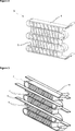
- Figure 3 – is the perspective view of the evaporator, the first air guiding plate and the second air guiding plate in another embodiment of the present invention.
- Figure 4 – is the sideways view of the compartment in another embodiment of the present invention.
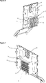
- Figure 5 — is the perspective view of the evaporator lid in another embodiment of the present invention.
- Figure 6 — is the perspective view of the evaporator lid, the first air guiding plate and the second air guiding plate in another embodiment of the present invention.
- Figure 7 — is the perspective view of the evaporator lid, the second air guiding plate and the vertical plate in yet another embodiment of the present invention.
- the refrigerator (1) comprises a compartment (2) wherein the foodstuffs to be cooled are placed, an evaporator (3) with front surface facing inside the compartment (2) and the rear surface facing the rear wall of the compartment (2),
- the refrigerator (1) of the present invention comprises, - at least one first air guiding plate (9) that is disposed on the evaporator lid (7) and that extends from the evaporator lid (7) to the front surface of the evaporator (4), and - at least one second air guiding plate (10) that is disposed on the rear wall of the compartment (2) and that extends from the compartment (2) rear wall to the rear surface of the evaporator (3).
- the evaporator (3) is positioned so as to be between the first air guiding plate (9) and the second air guiding plate (10).
- the air that is sucked by the fan (8) from the lower side of the evaporator chamber (6) is enabled to be carried inside the evaporator chamber (6) from the lower side of the evaporator (3) to the upper side of the evaporator (3) by contacting the fins (5).
- the first air guiding plate (9) enables the air to be guided between the evaporator (3) and the compartment (2) rear wall.
- the second air guiding plate (10) enables the air to be guided between the evaporator (3) and the compartment (2) rear wall, towards between the evaporator (3) and the evaporator lid (7) by passing over the fins (5).
- the refrigerator (1) comprises the first air guiding plate (9) that extends from the evaporator lid (7) to the refrigerant duct (4) and the second air guiding plate (10) that extends from the compartment (2) rear wall to the rear surface of the evaporator (3).
- the cold air is enabled to be passed over the fins (5) by preventing the first air guiding plate (9) and the second air guiding plate (10) from covering the fins (5).
- the refrigerator (1) comprises two vertical plates (11) that are disposed on the evaporator lid (7) and that extend from the evaporator lid (7) to the compartment (2) rear wall parallel to the fins (5) such that the evaporator (3) remains between them.
- the vertical plates (11) prevent the air guided onto the evaporator (3) from leaving the evaporator (3) through the opening between the evaporator (3) and the side walls of the compartment (2) without contacting the entire evaporator (3).
- the air delivered onto the evaporator (3) is carried up between two vertical plates (11) from the lowest refrigerant duct (4) of the evaporator (3) that is farthest to the fan (8) to the uppermost refrigerant duct (4) that is nearest to the fan (8). Consequently, the refrigeration performance of the evaporator (3) is improved.
- the refrigerator (1) comprises the second air guiding plates (10) disposed on the rear wall of the compartment (2) adjacently and spaced apart.
- the air that is guided towards between the evaporator (3) and the rear wall of the compartment (2) is guided onto the evaporator (3) by impacting the second air guiding plates (10).
- the second air guiding plates (10) are placed on the compartment (2) rear wall at certain intervals such that the air is enabled to disperse in equal amounts over the fins (5).
- the refrigerator (1) comprises more than one first air guiding plate (9) that extends to the front surface of the evaporator (3) and that is positioned vertically one on top of the other and spaced apart, and more than one second air guiding plate (10) that extends to the rear surface of the evaporator (3) and that is positioned and aligned so as to remain between the first air guiding plates (9).
- first air guiding plate (9) Upon impacting the first air guiding plate (9), the air is guided towards between the evaporator (3) and the compartment (2) rear wall, and upon impacting the second air guiding plate (10) while moving between the evaporator (3) and the compartment (2) rear wall, the air passes over the evaporator (3) and is guided towards between the evaporator lid (7) and the evaporator (3).
- the first air guiding plate (9) and the second air guiding plate (10) are placed successively, thus the air passes over the evaporator (3) by moving diagonally in between the area remaining between the evaporator (3) and the compartment (2) rear wall and the area remaining between the evaporator lid (7) and the evaporator (3) ( Figure 3 and Figure 6).
- the evaporator lid (7) is produced as a single piece with the first air guiding plate (9).
- the first air guiding plate (9) covers the opening between the evaporator (3) and the evaporator lid (7) and prevents the air from being directly guided to the fan (8) without contacting the evaporator (3).
- the evaporator lid (7) is produced as a single piece with the first air guiding plate (9) and the vertical plate (11)).
- the first air guiding plate (9) and the vertical plate (11) are not required to be mounted on the evaporator lid (7) separately, ease of production and ease of assembly are provided.
- the second air guiding plate (10) is produced as a single piece with the compartment (2) rear wall. Thus, it is facilitated to place the second air guiding plate (10) at the right position on the compartment (2) rear wall. Moreover, ease of production is provided by producing the second air guiding plate (10) together with the compartment (2) rear wall.
- the refrigerator (1) of the present invention almost all the air that is delivered to the evaporator (3) by the fan (8) by means of the first air guiding plate (9) and the second air guiding plate (10) is enabled to be guided onto the evaporator (3) thereby increasing the heat transfer between the air and the evaporator (3) and improving the refrigeration performance of the refrigerator (1).
Landscapes
- Engineering & Computer Science (AREA)
- Chemical & Material Sciences (AREA)
- Combustion & Propulsion (AREA)
- Physics & Mathematics (AREA)
- Mechanical Engineering (AREA)
- Thermal Sciences (AREA)
- General Engineering & Computer Science (AREA)
- Cold Air Circulating Systems And Constructional Details In Refrigerators (AREA)
Abstract
The present invention relates to a refrigerator (1) comprising a compartment (2) wherein the foodstuffs to be cooled are placed; an evaporator (3) with front surface facing inside the compartment (2) and the rear surface facing the rear wall of the compartment (2) that enables the cooling of the compartment (2) and that has more than one refrigerant duct (4) that is formed by bending a tube in serpentine form and that extends parallel to each other in the vertical plane and more than one fin (5) parallel to each other and extending vertically to the refrigerant duct (4); an evaporator chamber (6) wherein the evaporator (3) is placed; an evaporator lid (7) that separates the compartment (2) from the evaporator chamber (6) and a fan (8) that is disposed on the evaporator lid (7) and that provides the circulation of the air inside the compartment (2) by passing it over the evaporator (3).
Description
The present invention relates to a refrigerator that comprises an evaporator which provides the cooling of the compartments with the air being blown thereover by the fan.
Refrigerators are generally formed of two compartments, namely the freezer compartment and the cooling compartment. In some refrigerators, the freezer compartment is cooled by the evaporator in the refrigeration cycle and the cooling compartment (the fresh food compartment) is cooled by the transfer of cold air from the freezer compartment. In widely-used no-frost double door refrigerators, the freezer compartment and the cooling compartment are separated by a compartment wall and are cooled independently from each other with forced convection by means of separate evaporators and fans that are disposed close to the evaporators.
In order to cool the freezer compartment in refrigerators, generally a fin – tube type evaporator is used, that is disposed parallel to the rear wall and behind a cover situated on the side of the rear wall. The air blown into the compartment by the fan providing air circulation is sucked through the holes arranged at the lower part of the compartment and delivered over the evaporator, the air cooling down while passing over the evaporator is delivered back into the compartment by passing through the blowing holes on the cover, thus air circulation in the freezer compartment is realized.
In the state of the art Japanese Patent Application No. JP2002107069, the contact surface with the air is increased by bending the micro-channel tubes of the evaporator in the spiral form.
The aim of the present invention is the realization of a refrigerator, wherein the refrigeration efficiency is increased by improving the heat transfer between the evaporator and the air that is passed thereover by the fan.
The refrigerator realized in order to attain the aim of the present invention, explicated in the first claim and the respective claims thereof, comprises an evaporator that provides the cooling of the compartment and that has more than one refrigerant duct that extends parallel to one another in the vertical plane and more than one fin parallel to one another and extending vertically to the refrigerant duct; an evaporator chamber wherein the evaporator is placed; an evaporator lid that separates the compartment from the evaporator chamber, and a fan that is disposed on the evaporator lid and that enables the air to be passed over the evaporator and be circulated inside the compartment. The air received by the fan from the lower side of the evaporator chamber moves in the upward direction along the evaporator chamber and reaches the fan that is positioned at the upper side of the evaporator lid.
The refrigerator of the present invention comprises:
- at least one first air guiding plate that is disposed on the evaporator lid and that extends from the evaporator lid to the front surface of the evaporator,
- at least one second air guiding plate that is disposed on the rear wall of the compartment and that extends from the compartment rear wall to the rear surface of the evaporator. The first air guiding plate enables the air that moves between the evaporator lid and the evaporator to be guided onto the evaporator while the second air guiding plate enables the air that moves between the compartment rear wall and the evaporator to be guided onto the evaporator. Thus, the air that is directly guided to the fan without contacting the evaporator is enabled to be cooled by passing over the evaporator and a better cooling performance is obtained inside the compartment.
- at least one first air guiding plate that is disposed on the evaporator lid and that extends from the evaporator lid to the front surface of the evaporator,
- at least one second air guiding plate that is disposed on the rear wall of the compartment and that extends from the compartment rear wall to the rear surface of the evaporator. The first air guiding plate enables the air that moves between the evaporator lid and the evaporator to be guided onto the evaporator while the second air guiding plate enables the air that moves between the compartment rear wall and the evaporator to be guided onto the evaporator. Thus, the air that is directly guided to the fan without contacting the evaporator is enabled to be cooled by passing over the evaporator and a better cooling performance is obtained inside the compartment.
In an embodiment of the present invention, the refrigerator comprises the first air guiding plate that extends from the evaporator lid to the refrigerant duct and at least a second air guiding plate that extends from the compartment rear wall to the rear surface of the evaporator. Thus, the air guided by the first air guiding plate and the second air guiding plate is enabled to be directly delivered onto the fins.
In an embodiment of the present invention, the refrigerator comprises two vertical plates that are disposed on the evaporator lid and that extend from the evaporator lid to the compartment rear wall parallel to the fins such that the evaporator remains between them. The vertical plates prevent the air passing over the evaporator from going out the sides of the evaporator and being directed to the fan without contacting the evaporator. The air that moves outwards from two sides of the evaporator is guided back onto the evaporator after impacting the vertical plates. Thus, the refrigeration performance of the evaporator is improved by enabling the air to be guided to the fan after being cooled along the evaporator.
In another embodiment of the present invention, the refrigerator comprises the second air guiding plates disposed on the rear wall of the compartment adjacently and spaced apart from each other. The air that is guided towards between the evaporator and the rear wall of the compartment is guided onto the evaporator by impacting the second air guiding plates. The second air guiding plates are placed on the compartment rear wall with certain intervals such that the air is enabled to disperse in equal amounts over the fins. The movement direction of the air guided between the evaporator and the rear wall of the compartment is changed such that the air passes over the evaporator after impacting the second air guiding plates. The second air guiding plates are placed angularly such that the movement of the air is not hindered. The number and size of the second air guiding plates are determined depending on the dimensions of the evaporator such that air is enabled to disperse equally over the evaporator fins.
In another embodiment of the present invention, the refrigerator comprises more than one first air guiding plate that extends to the front surface of the evaporator, positioned spaced apart and vertically one on top of the other, and more than one second air guiding plate that extends to the rear surface of the evaporator, positioned and aligned so as to remain between the first air guiding plates. Each time the air contacts the first air guiding plate and the second air guiding plate, it is guided onto the evaporator. Thus, the air, during its movement from the base of the evaporator chamber towards the fan, is enabled to move zigzag and to pass over the evaporator more than once, thus increasing the heat transfer between the air and the evaporator and the air is enabled to be cooled better.
In another embodiment of the present invention, the evaporator lid is produced as a single piece with the first air guiding plate. The evaporator lid and the first air guiding plate are produced as a single piece by the injection method using a suitable injection mold. Thus, ease of production and ease of assembly are provided.
In another embodiment of the present invention, the evaporator lid is produced as a single piece with the first air guiding plate and the vertical plate. Thus, a frame structure is formed on the evaporator lid.
In another embodiment of the present invention, the compartment rear wall is produced as a single piece with the second air guiding plate. Thus, an additional assembly operation is not required for mounting the second air guiding plate on the compartment rear wall, and the positioning of the second air guiding plate on the compartment rear wall at the correct position is facilitated.
By means of the present invention, the air that is guided by the fan is delivered onto the evaporator by means of the air guiding plates, thereby increasing the amount of air passing over the evaporator and improving the refrigeration effectiveness of the evaporator.
The refrigerator realized in order to attain the aim of the present invention is illustrated in the attached figures, where:
Figure 1 – is the schematic view of a refrigerator.
Figure 2 – is the perspective view of the evaporator in an embodiment of the present invention.
Figure 3 – is the perspective view of the evaporator, the first air guiding plate and the second air guiding plate in another embodiment of the present invention.
Figure 4 – is the sideways view of the compartment in another embodiment of the present invention.
Figure 5 – is the perspective view of the evaporator lid in another embodiment of the present invention.
Figure 6 – is the perspective view of the evaporator lid, the first air guiding plate and the second air guiding plate in another embodiment of the present invention.
Figure 7 – is the perspective view of the evaporator lid, the second air guiding plate and the vertical plate in yet another embodiment of the present invention.
The elements illustrated in the figures are numbered as follows:
- Refrigerator
- Compartment
- Evaporator
- Refrigerant duct
- Fin
- Evaporator chamber
- Evaporator lid
- Fan
- First air guiding plate
- Second air guiding plate
- Vertical plate
The refrigerator (1) comprises a compartment (2) wherein the foodstuffs to be cooled are placed, an evaporator (3) with front surface facing inside the compartment (2) and the rear surface facing the rear wall of the compartment (2),
- that enables the cooling of the compartment (2) and
- that has more than one refrigerant duct (4) that is formed by bending a tube in serpentine form and that extends parallel to each other in the vertical plane
- more than one fin (5) parallel to each other and extending vertically to the refrigerant duct (4),
an evaporator chamber (6) wherein the evaporator (3) is placed, an evaporator lid (7) that separates the compartment (2) from the evaporator chamber (6) and a fan (8) that is disposed on the evaporator lid (7) and that provides the circulation of the air inside the compartment (2) by passing it over the evaporator (3).
The refrigerator (1) of the present invention comprises,
- at least one first air guiding plate (9) that is disposed on the evaporator lid (7) and that extends from the evaporator lid (7) to the front surface of the evaporator (4), and
- at least one second air guiding plate (10) that is disposed on the rear wall
of the compartment (2) and that extends from the compartment (2) rear wall to the rear surface of the evaporator (3). The evaporator (3) is positioned so as to be between the first air guiding plate (9) and the second air guiding plate (10). By means of the first air guiding plate (9) and the second air guiding plate (10), the air that is sucked by the fan (8) from the lower side of the evaporator chamber (6) is enabled to be carried inside the evaporator chamber (6) from the lower side of the evaporator (3) to the upper side of the evaporator (3) by contacting the fins (5). The first air guiding plate (9) enables the air to be guided between the evaporator (3) and the compartment (2) rear wall. The second air guiding plate (10) enables the air to be guided between the evaporator (3) and the compartment (2) rear wall, towards between the evaporator (3) and the evaporator lid (7) by passing over the fins (5).
- at least one first air guiding plate (9) that is disposed on the evaporator lid (7) and that extends from the evaporator lid (7) to the front surface of the evaporator (4), and
- at least one second air guiding plate (10) that is disposed on the rear wall
of the compartment (2) and that extends from the compartment (2) rear wall to the rear surface of the evaporator (3). The evaporator (3) is positioned so as to be between the first air guiding plate (9) and the second air guiding plate (10). By means of the first air guiding plate (9) and the second air guiding plate (10), the air that is sucked by the fan (8) from the lower side of the evaporator chamber (6) is enabled to be carried inside the evaporator chamber (6) from the lower side of the evaporator (3) to the upper side of the evaporator (3) by contacting the fins (5). The first air guiding plate (9) enables the air to be guided between the evaporator (3) and the compartment (2) rear wall. The second air guiding plate (10) enables the air to be guided between the evaporator (3) and the compartment (2) rear wall, towards between the evaporator (3) and the evaporator lid (7) by passing over the fins (5).
In an embodiment of the present invention, the refrigerator (1) comprises the first air guiding plate (9) that extends from the evaporator lid (7) to the refrigerant duct (4) and the second air guiding plate (10) that extends from the compartment (2) rear wall to the rear surface of the evaporator (3). Thus, the cold air is enabled to be passed over the fins (5) by preventing the first air guiding plate (9) and the second air guiding plate (10) from covering the fins (5).
In another embodiment of the present invention, the refrigerator (1) comprises two vertical plates (11) that are disposed on the evaporator lid (7) and that extend from the evaporator lid (7) to the compartment (2) rear wall parallel to the fins (5) such that the evaporator (3) remains between them. The vertical plates (11) prevent the air guided onto the evaporator (3) from leaving the evaporator (3) through the opening between the evaporator (3) and the side walls of the compartment (2) without contacting the entire evaporator (3). The air delivered onto the evaporator (3) is carried up between two vertical plates (11) from the lowest refrigerant duct (4) of the evaporator (3) that is farthest to the fan (8) to the uppermost refrigerant duct (4) that is nearest to the fan (8). Consequently, the refrigeration performance of the evaporator (3) is improved.
In another embodiment of the present invention, the refrigerator (1) comprises the second air guiding plates (10) disposed on the rear wall of the compartment (2) adjacently and spaced apart. The air that is guided towards between the evaporator (3) and the rear wall of the compartment (2) is guided onto the evaporator (3) by impacting the second air guiding plates (10). The second air guiding plates (10) are placed on the compartment (2) rear wall at certain intervals such that the air is enabled to disperse in equal amounts over the fins (5).
In another embodiment of the present invention, the refrigerator (1) comprises more than one first air guiding plate (9) that extends to the front surface of the evaporator (3) and that is positioned vertically one on top of the other and spaced apart, and more than one second air guiding plate (10) that extends to the rear surface of the evaporator (3) and that is positioned and aligned so as to remain between the first air guiding plates (9). Upon impacting the first air guiding plate (9), the air is guided towards between the evaporator (3) and the compartment (2) rear wall, and upon impacting the second air guiding plate (10) while moving between the evaporator (3) and the compartment (2) rear wall, the air passes over the evaporator (3) and is guided towards between the evaporator lid (7) and the evaporator (3). The first air guiding plate (9) and the second air guiding plate (10) are placed successively, thus the air passes over the evaporator (3) by moving diagonally in between the area remaining between the evaporator (3) and the compartment (2) rear wall and the area remaining between the evaporator lid (7) and the evaporator (3) (Figure 3 and Figure 6).
In another embodiment of the present invention, the evaporator lid (7) is produced as a single piece with the first air guiding plate (9). Thus, it is facilitated to place the first air guiding plate (9) at the right position on the evaporator lid (7). Moreover, when the evaporator lid (7) is placed into the refrigerator (1), the first air guiding plate (9) covers the opening between the evaporator (3) and the evaporator lid (7) and prevents the air from being directly guided to the fan (8) without contacting the evaporator (3).
In another embodiment of the present invention, the evaporator lid (7) is produced as a single piece with the first air guiding plate (9) and the vertical plate (11)). Thus, the first air guiding plate (9) and the vertical plate (11) are not required to be mounted on the evaporator lid (7) separately, ease of production and ease of assembly are provided.
In another embodiment of the present invention, the second air guiding plate (10) is produced as a single piece with the compartment (2) rear wall. Thus, it is facilitated to place the second air guiding plate (10) at the right position on the compartment (2) rear wall. Moreover, ease of production is provided by producing the second air guiding plate (10) together with the compartment (2) rear wall.
In the refrigerator (1) of the present invention, almost all the air that is delivered to the evaporator (3) by the fan (8) by means of the first air guiding plate (9) and the second air guiding plate (10) is enabled to be guided onto the evaporator (3) thereby increasing the heat transfer between the air and the evaporator (3) and improving the refrigeration performance of the refrigerator (1).
Claims (8)
- A refrigerator (1) comprising a compartment (2) wherein foodstuffs to be cooled are placed, an evaporator (3) with front surface facing inside the compartment (2) and the rear surface facing the rear wall of the compartment (2),- that enables the cooling of the compartment (2) and- that has more than one refrigerant duct (4) that is formed by bending a tube in serpentine form and that extends parallel to each other in the vertical plane- more than one fin (5) parallel to each other and extending vertically to the refrigerant duct (4),an evaporator chamber (6) wherein the evaporator (3) is placed, an evaporator lid (7) that separates the compartment (2) from the evaporator chamber (6) and a fan (8) that is disposed on the evaporator lid (7) and that provides the circulation of the air inside the compartment (2) by passing over the evaporator (3), characterized by- at least one first air guiding plate (9) that is disposed on the evaporator lid (7) and that extends from the evaporator lid (7) to the front surface of the evaporator (4), and- at least one second air guiding plate (10) that is disposed on the rear wall of the compartment (2) and that extends from the compartment (2) rear wall to the rear surface of the evaporator (3).
- A refrigerator (1) as in Claim 1, characterized by the first air guiding plate (9) that extends from the evaporator lid (7) to the refrigerant duct (4) and the second air guiding plate (10) that extends from the compartment (2) rear wall to the rear surface of the evaporator (3).
- A refrigerator (1) as in any one of the above claims, characterized by two vertical plates (11) that are disposed on the evaporator lid (7) and that extend from the evaporator lid (7) to the compartment (2) rear wall parallel to the fins (5) such that the evaporator (3) remains between them.
- A refrigerator (1) as in any one of the above claims, characterized by the second air guiding plates (10) disposed on the rear wall of the compartment (2) adjacently and spaced apart.
- A refrigerator (1) as in any one of the above claims, characterized by more than one first air guiding plate (9) that extends to the front surface of the evaporator (3) and that is positioned vertically one on top of the other and spaced apart, and more than one second air guiding plate (10) that extends to the rear surface of the evaporator (3) and that is positioned and aligned so as to remain between the first air guiding plates (9).
- A refrigerator (1) as in any one of the above claims, characterized by the first air guiding plate (9) that is produced as a single piece with the evaporator lid (7).
- A refrigerator (1) as in any one of the above claims, characterized by the first air guiding plate (9) and the vertical plate (11) that are produced as a single piece with the evaporator lid (7).
- A refrigerator (1) as in any one of the above claims, characterized by the second air guiding plate (10) that is produced as a single piece with the compartment (2) rear wall.
Applications Claiming Priority (2)
| Application Number | Priority Date | Filing Date | Title |
|---|---|---|---|
| TR201416343 | 2014-12-31 | ||
| TRA2014/16343 | 2014-12-31 |
Publications (1)
| Publication Number | Publication Date |
|---|---|
| WO2016107700A1 true WO2016107700A1 (en) | 2016-07-07 |
Family
ID=54780263
Family Applications (1)
| Application Number | Title | Priority Date | Filing Date |
|---|---|---|---|
| PCT/EP2015/077477 Ceased WO2016107700A1 (en) | 2014-12-31 | 2015-11-24 | A refrigerator comprising an evaporator with improved refrigeration efficiency |
Country Status (1)
| Country | Link |
|---|---|
| WO (1) | WO2016107700A1 (en) |
Cited By (1)
| Publication number | Priority date | Publication date | Assignee | Title |
|---|---|---|---|---|
| CN112781401A (en) * | 2019-11-06 | 2021-05-11 | 广东美的白色家电技术创新中心有限公司 | Heat exchange device air duct assembly and refrigeration equipment |
Citations (6)
| Publication number | Priority date | Publication date | Assignee | Title |
|---|---|---|---|---|
| JPH04190074A (en) * | 1990-11-26 | 1992-07-08 | Sanyo Electric Co Ltd | frozen case |
| JP2001050636A (en) * | 1999-08-12 | 2001-02-23 | Hitachi Ltd | refrigerator |
| US6272876B1 (en) * | 2000-03-22 | 2001-08-14 | Zero Zone, Inc. | Display freezer having evaporator unit |
| JP2002107069A (en) | 2000-09-28 | 2002-04-10 | Sanyo Electric Co Ltd | Heat exchanger and heat pump water heater using the same |
| JP2002228329A (en) * | 2001-01-31 | 2002-08-14 | Sanyo Electric Co Ltd | Freezer refrigerator |
| DE102011118511A1 (en) * | 2011-10-27 | 2013-05-02 | Liebherr-Hausgeräte Ochsenhausen GmbH | Evaporator module for refrigerating and/or freezing appliance, has air guidance device having air inlet, which is provided for guiding the air to the evaporator element |
-
2015
- 2015-11-24 WO PCT/EP2015/077477 patent/WO2016107700A1/en not_active Ceased
Patent Citations (6)
| Publication number | Priority date | Publication date | Assignee | Title |
|---|---|---|---|---|
| JPH04190074A (en) * | 1990-11-26 | 1992-07-08 | Sanyo Electric Co Ltd | frozen case |
| JP2001050636A (en) * | 1999-08-12 | 2001-02-23 | Hitachi Ltd | refrigerator |
| US6272876B1 (en) * | 2000-03-22 | 2001-08-14 | Zero Zone, Inc. | Display freezer having evaporator unit |
| JP2002107069A (en) | 2000-09-28 | 2002-04-10 | Sanyo Electric Co Ltd | Heat exchanger and heat pump water heater using the same |
| JP2002228329A (en) * | 2001-01-31 | 2002-08-14 | Sanyo Electric Co Ltd | Freezer refrigerator |
| DE102011118511A1 (en) * | 2011-10-27 | 2013-05-02 | Liebherr-Hausgeräte Ochsenhausen GmbH | Evaporator module for refrigerating and/or freezing appliance, has air guidance device having air inlet, which is provided for guiding the air to the evaporator element |
Cited By (2)
| Publication number | Priority date | Publication date | Assignee | Title |
|---|---|---|---|---|
| CN112781401A (en) * | 2019-11-06 | 2021-05-11 | 广东美的白色家电技术创新中心有限公司 | Heat exchange device air duct assembly and refrigeration equipment |
| CN112781401B (en) * | 2019-11-06 | 2023-07-25 | 广东美的白色家电技术创新中心有限公司 | Heat exchange device air duct components and refrigeration equipment |
Similar Documents
| Publication | Publication Date | Title |
|---|---|---|
| US10718561B2 (en) | Refrigerator and method for controlling temperature of a refrigerating chamber | |
| US9857121B2 (en) | Ice maker of refrigerator and manufacturing method for the same | |
| US20100257886A1 (en) | Refrigeration device | |
| CN111947373B (en) | refrigerator | |
| CN111947368B (en) | refrigerator | |
| US4353223A (en) | Refrigerator with a large refrigeration chamber cooled by natural convection | |
| JP4895958B2 (en) | refrigerator | |
| KR20180037539A (en) | Rrigerator | |
| CN111609620B (en) | Refrigerator with two-stage evaporator | |
| US20180031301A1 (en) | Refrigerator | |
| CN216409409U (en) | freezer | |
| CN111609619B (en) | Refrigerator with air return openings formed in two side walls of refrigerator body | |
| CN111351282B (en) | Horizontal refrigerator | |
| EP2938945A1 (en) | A defrost water evaporation tray, a condenser retainer and a cooling device wherein the same are used | |
| JP2014077615A (en) | Refrigerator | |
| KR20110086413A (en) | Refrigerator | |
| US20220034558A1 (en) | Refrigerator | |
| WO2012143466A2 (en) | Refrigerator with efficient cooling evaporator | |
| CN109764597B (en) | Refrigerator and refrigerating method thereof | |
| CN111609623B (en) | Refrigerator with L-shaped condenser | |
| CN111609617B (en) | Refrigerator with air return openings positioned on two side walls of box body and respectively corresponding to evaporators | |
| JP5367553B2 (en) | Cooling storage | |
| JP2015148403A (en) | refrigerator | |
| JP2014035141A (en) | Refrigerator-freezer | |
| KR20110087917A (en) | Refrigerator |
Legal Events
| Date | Code | Title | Description |
|---|---|---|---|
| 121 | Ep: the epo has been informed by wipo that ep was designated in this application |
Ref document number: 15804350 Country of ref document: EP Kind code of ref document: A1 |
|
| NENP | Non-entry into the national phase |
Ref country code: DE |
|
| 122 | Ep: pct application non-entry in european phase |
Ref document number: 15804350 Country of ref document: EP Kind code of ref document: A1 |