WO2016104641A1 - Endoscope system - Google Patents
Endoscope system Download PDFInfo
- Publication number
- WO2016104641A1 WO2016104641A1 PCT/JP2015/086094 JP2015086094W WO2016104641A1 WO 2016104641 A1 WO2016104641 A1 WO 2016104641A1 JP 2015086094 W JP2015086094 W JP 2015086094W WO 2016104641 A1 WO2016104641 A1 WO 2016104641A1
- Authority
- WO
- WIPO (PCT)
- Prior art keywords
- video processor
- peripheral device
- command
- processing unit
- communication
- Prior art date
Links
Images


Classifications
-
- A—HUMAN NECESSITIES
- A61—MEDICAL OR VETERINARY SCIENCE; HYGIENE
- A61B—DIAGNOSIS; SURGERY; IDENTIFICATION
- A61B1/00—Instruments for performing medical examinations of the interior of cavities or tubes of the body by visual or photographical inspection, e.g. endoscopes; Illuminating arrangements therefor
- A61B1/00002—Operational features of endoscopes
- A61B1/00004—Operational features of endoscopes characterised by electronic signal processing
- A61B1/00006—Operational features of endoscopes characterised by electronic signal processing of control signals
-
- A—HUMAN NECESSITIES
- A61—MEDICAL OR VETERINARY SCIENCE; HYGIENE
- A61B—DIAGNOSIS; SURGERY; IDENTIFICATION
- A61B1/00—Instruments for performing medical examinations of the interior of cavities or tubes of the body by visual or photographical inspection, e.g. endoscopes; Illuminating arrangements therefor
- A61B1/00002—Operational features of endoscopes
- A61B1/00011—Operational features of endoscopes characterised by signal transmission
-
- A—HUMAN NECESSITIES
- A61—MEDICAL OR VETERINARY SCIENCE; HYGIENE
- A61B—DIAGNOSIS; SURGERY; IDENTIFICATION
- A61B1/00—Instruments for performing medical examinations of the interior of cavities or tubes of the body by visual or photographical inspection, e.g. endoscopes; Illuminating arrangements therefor
- A61B1/00002—Operational features of endoscopes
- A61B1/00039—Operational features of endoscopes provided with input arrangements for the user
-
- A—HUMAN NECESSITIES
- A61—MEDICAL OR VETERINARY SCIENCE; HYGIENE
- A61B—DIAGNOSIS; SURGERY; IDENTIFICATION
- A61B1/00—Instruments for performing medical examinations of the interior of cavities or tubes of the body by visual or photographical inspection, e.g. endoscopes; Illuminating arrangements therefor
- A61B1/04—Instruments for performing medical examinations of the interior of cavities or tubes of the body by visual or photographical inspection, e.g. endoscopes; Illuminating arrangements therefor combined with photographic or television appliances
- A61B1/045—Control thereof
-
- A—HUMAN NECESSITIES
- A61—MEDICAL OR VETERINARY SCIENCE; HYGIENE
- A61B—DIAGNOSIS; SURGERY; IDENTIFICATION
- A61B1/00—Instruments for performing medical examinations of the interior of cavities or tubes of the body by visual or photographical inspection, e.g. endoscopes; Illuminating arrangements therefor
- A61B1/00002—Operational features of endoscopes
- A61B1/00004—Operational features of endoscopes characterised by electronic signal processing
- A61B1/00009—Operational features of endoscopes characterised by electronic signal processing of image signals during a use of endoscope
-
- H—ELECTRICITY
- H04—ELECTRIC COMMUNICATION TECHNIQUE
- H04N—PICTORIAL COMMUNICATION, e.g. TELEVISION
- H04N21/00—Selective content distribution, e.g. interactive television or video on demand [VOD]
- H04N21/40—Client devices specifically adapted for the reception of or interaction with content, e.g. set-top-box [STB]; Operations thereof
- H04N21/43—Processing of content or additional data, e.g. demultiplexing additional data from a digital video stream; Elementary client operations, e.g. monitoring of home network or synchronising decoder's clock; Client middleware
- H04N21/436—Interfacing a local distribution network, e.g. communicating with another STB or one or more peripheral devices inside the home
Definitions
- the present invention relates to an endoscope system, and more particularly to an endoscope system including an endoscope video processor and a peripheral device that communicates with the endoscope video processor and is used together with the endoscope video processor.
- an endoscope video processor (hereinafter abbreviated as a processor) that performs processing of an endoscope image and the like is connected to another device via a network, and is determined according to a command from the other device. Execute the process. Commands are transmitted and received between the processor and other devices such as peripheral devices using a predetermined protocol (for example, Patent Document 1).
- a device that has received data determines its destination from information attached to the data. If the data is addressed to the own device, the data is taken in. If the data is addressed to another device, the data is transferred (for example, Patent Document 2).
- JP 2007-111358 A Japanese Patent Laid-Open No. 11-4238
- an endoscope video processor has a longer life cycle than a peripheral device, and a long period from when it is released to when a next-generation machine is released.
- peripheral devices have a relatively short life cycle. For this reason, when a higher performance successor model is released as a peripheral device, there are relatively many cases in which it is connected to an endoscope video processor instead of the conventional model. .
- the present invention introduces a newly released peripheral device to the system by a simple method in an endoscope system having an endoscope video processor and a peripheral device connected to and used with the endoscope video processor. It is an object to provide a technology that makes it possible.
- an endoscope having an endoscope video processor and a peripheral device having functions of a plurality of peripheral devices and capable of communicating with the endoscope video processor.
- the endoscope video processor and the peripheral device are positioned above the destination management unit, and a destination management unit that performs destination management processing in communication between the endoscope video processor and the peripheral device.
- a plurality of communication processing units that respectively correspond to the functions of the plurality of peripheral devices and process a command, and the destination management unit, when transmitting the command, the plurality of communication processing units Is given to the transmission command, and when the command is received, the destination information given to the reception command is used as the destination information. Determining a destination of the signal commands, characterized by distributing the received command to the communication processing unit indicated by the destination of the plurality of communication processor.
- the newly released peripheral device is systemized by a simple method. Can be introduced.
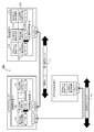
- FIG. 1 is a diagram illustrating a method for introducing a peripheral device by the endoscope system according to the present embodiment.
- An endoscope system 100 shown in FIG. 1 includes an endoscope video processor (hereinafter abbreviated as a video processor) 1 and a peripheral device 2, and the video processor 1 and the peripheral device 2 are mutually connected via respective communication connectors. It is connected to the.
- a video processor hereinafter abbreviated as a video processor
- the peripheral device 2 includes function processing units 21A to 21Z for the peripheral devices A to Z, communication processing units 22A to 22Z for the peripheral devices A to Z, and a destination management processing unit 23.
- the peripheral device 2 is used together with the video processor 1 and a scope not shown in FIG. 1 when an operator performs an examination or an operation using the endoscope system 100, and is provided by the peripheral devices AZ. Implement various functions.
- Each of the peripheral devices A to Z includes a function processing unit 21 that executes processing related to each function, and a communication processing unit 22 that performs communication processing necessary for executing the function.
- the video processor 1 includes a control processing unit 11, a communication processing unit 12 (12A to 12Z) of each peripheral device A to Z, and a destination management processing unit 13.
- the video processor 1 generates an image signal by processing an imaging signal obtained by imaging with a scope not shown in FIG. Further, the video processor 1 realizes the functions of the peripheral devices A to Z by executing predetermined processing such as control of the endoscope device in accordance with commands from the peripheral devices A to Z of the peripheral device 2.
- the video processor 1 and the peripheral device 2 include destination management processing units 13 and 23 between the communication processing units 12 and 22 and the communication drivers a and c.
- the destination management processing units 13 and 23 are communication modules that perform command destination management processing.
- the destination management processing units 13 and 23 receive a command to be transmitted from the higher-level communication processing units 12 and 22 to the partner device, the destination management processing units 13 and 23 perform a process of adding information indicating the destination to the command.
- the destination management processing units 13 and 23 receive a command from the communication processing units 22 and 12 of the counterpart device, the destination management processing units 13 and 23 refer to information indicating the destination given to the command and send the command via the ports A to Z.
- a process of transferring to the communication processing units 12 and 22 of the peripheral devices A to Z corresponding to the own device is executed.
- the function processing unit 21B of the peripheral device 2 executes processing necessary for realizing the function of the peripheral device B in the endoscope system 100.
- the function processing unit 21B needs to transmit a command to the video processor 1 when executing the function of the peripheral device B
- the function processing unit 21B notifies the communication processing unit 22B of the fact.
- the communication processing unit 22B generates a necessary command and passes the command generated via the port B to the destination management processing unit 23.
- the ports A to Z are provided to the upper communication processing units 22A to 22Z by the destination management processing unit 23, and are provided to identify the communication processing units 22A to 22Z.
- the destination management processing unit 23 Upon receiving a command from the communication processing unit 22B, the destination management processing unit 23 performs command destination management processing. Specifically, the destination management processing unit 23 gives information indicating that the destination of the command is the peripheral device B to a predetermined position of the command, for example, a predetermined field of the header portion. Then, the destination management processing unit 23 sends a command with information indicating the destination to the video processor 1 via the driver b and the connector b (see reference numeral (1) in FIG. 1).
- the destination management processing unit 13 of the video processor 1 When the destination management processing unit 13 of the video processor 1 receives a command via the connector a and the driver a, the destination management processing unit 13 executes a destination management process for the command. Specifically, the destination management processing unit 13 determines information indicating a destination given to a predetermined position of the received command, and sends the command to the predetermined communication processing unit 12 among the communication processing units 12A to 12Z. Distribute. In the example of FIG. 1, information indicating that the destination is the peripheral device B is given. Therefore, the destination management processing unit 13 transfers the command to the communication processing unit 12B via the port B (see reference numeral (2) in FIG. 1).
- the communication processing unit 12B receives the command via the port B (see reference numeral (3) in FIG. 1).
- the communication processing unit 12B performs necessary processing according to the received command.
- the control processing unit 11 controls each unit constituting the video processor 1.
- the control processing unit 11 controls each unit according to control of processing in which the destination management processing unit 13 sends and receives commands to and from the peripheral device 2 and commands received from the peripheral device 2 by the communication processing unit 12B.
- the control such as executing the process is performed.
- the video processor 1 performs processing necessary for implementing the functions of the peripheral device B.
- 22A to 22Z transmit the command
- the destination management processing units 13 and 23 add information indicating the destination to the command, and send the command to the partner apparatus.
- the destination management processing units 13 and 23 determine information indicating the destination given to the command, and transfer the command to the predetermined communication processing units 12A to 12Z and 22A to 22Z. To do.
- peripheral device 2 and the video processor 1 need to implement the same protocol.
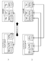
- a driver and a connector are connected to each other according to the function (peripheral devices A to Z) used, or as shown in FIG. As shown, all drivers and connectors had to be connected in advance.
- FIG. 2A only a part of the functions can be used even if the peripheral device has a plurality of functions AZ.
- FIG. 2B since it is necessary to physically connect the peripheral devices A to Z, the wiring becomes complicated.
- the destination management processing units 13 and 23 of the video processor 1 and the peripheral device 2 are connected to any of the peripheral devices A to Z. Is given to the command, and the command is transferred to the predetermined communication processing units 12 and 22 of the own apparatus.
- the destination management processing units 13 and 23 determine which of the peripheral devices A to Z is the destination command, and distribute the command to the corresponding communication processing units 12 and 22. To do.
- communication can be performed between the video processor 1 and the peripheral device 2 without being aware of the connector, that is, the physical connection.
- the functions of the peripheral devices A to Z may be changed from the conventional model.
- the function of the peripheral device B (function processing unit 21 and communication processing unit 22) is changed from the conventional model.
- the newly released peripheral device 2 can be introduced into the endoscope system 100 by a simple method, and the video processor 1 and the peripheral device 2 can be linked.
- the endoscope system 100 can be configured such that the video processor 1 can communicate with existing peripheral devices.
- the existing peripheral device 2 ′ shown in FIG. 1 is connected to the connector c of the video processor 1 through the connector d.
- the existing peripheral device 2 ′ does not have the destination management processing unit 23.
- the existing peripheral device 2 does not perform the destination management process and sends a command to which information indicating the destination is not given to the video processor 1 (see reference numeral (4) in FIG. 1).
- the video processor 1 appropriately determines the destination and transfers the command to the predetermined communication processing unit 12 even when the command for which the destination management processing is not performed is received.
- the destination management processing unit 13 of the video processor 1 determines that no destination is given as a result of referring to the information indicating the destination given to the command, it further passes through any communication connector. Refers to information indicating whether a command has been received.
- the destination management processing unit 13 determines which communication connector is used for each connected peripheral device 2, 2 ′ and which peripheral device has the peripheral device. In FIG. 1, it is held in a storage means (not shown).
- the communication processing unit 12 corresponding to the connector c determines “the communication processing unit 12A of the peripheral device A”.
- the destination management processing unit 13 transfers the command received from the existing peripheral device 2 ′ to the communication processing unit 12A via the port A.
- the video processor 1 can communicate not only with the newly released peripheral device 2 but also with the existing peripheral device 2 ′. . Since the peripheral device 2 has a shorter life cycle than the video processor 1, the newly released peripheral device 2 may have functions that are not present in existing peripheral devices. Even when a function is newly added, it is not necessary to perform communication with the video processor 1 via the connector corresponding to the new function by executing the command destination management process. That is, the destination management processing unit 13 determines which communication processing unit 12 is the destination of the command, and sends it to the destination communication processing unit 12 via the port corresponding to the communication processing unit 12. Since it is transferred, it is not necessary to be aware of the connector and driver.
- a command transmitted from the existing peripheral device 2 ′ can be determined by the corresponding communication processing unit 12 in the destination management processing unit 13 and transferred. This makes it possible to easily introduce the newly released peripheral device 2 into the endoscope system 100 while ensuring compatibility with the existing peripheral device 2 ′.
- a function of a peripheral device n (a function processing unit 21n and a communication processing unit 22n) among the newly released peripheral devices 2 is changed from the conventional model.
- the present invention relates to a method for introducing the peripheral device 2 into the endoscope system 100.
- a certain peripheral device n is a completely new device, and the video processor 1 has a communication processing unit corresponding to the function.
- the present invention relates to a method for introducing the peripheral device 2 into the endoscope system 100 when there is no such device.
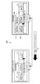
- FIG. 3 is a diagram illustrating a method for introducing the peripheral device 2 by the endoscope system according to the present embodiment.
- the operations of the respective parts constituting the video processor 1 and the peripheral device 2 are the same as those in the above embodiment, and the destination management processing units 13 and 23 perform the destination management process as in the above embodiment.
- the destination management processing units 13 and 23 assign information indicating a destination to a command to be transmitted at a predetermined position, and with respect to the received command, refer to the information indicating the destination to process the command with a predetermined communication process. Distribute to the department.
- the function of the peripheral device B is added, and a function processing unit 21B and a communication processing unit 22B are provided.
- the video processor 1 does not include a corresponding communication processing unit 12B.
- a method in which the video processor 1 implements the function of the peripheral device B in cooperation with the peripheral device 2 including the new peripheral device B will be described as an example.
- the information of the counterpart device is acquired in advance.
- the information acquired here includes the configuration of the communication processing units 12 and 22 included in the video processor 1 or the peripheral device 2 that is the counterpart device.
- information that the communication processing unit 12 of the video processor 1 is composed of the communication processing units 12A, 12C,... 21F of the peripheral devices A, C,.
- the destination management processing unit 13 of the video processor 1 compares the information acquired from the peripheral device 2 with the information of its own device. As a result, the peripheral device 2 includes the “communication processing unit 22B of the peripheral device B”. Recognize that the device does not have this. Therefore, the destination management processing unit 13 tentatively connects the peripheral device B of the peripheral device 2 with the peripheral device 2 as “a friend of the peripheral device A” (see reference numeral (1) in FIG. 3). . The destination management processing unit 13 holds information indicating that the peripheral device B is processed as a friend of the peripheral device A in the storage unit.
- process peripheral device n as a friend of peripheral device m means that a command destined for peripheral device n is distributed to communication processing unit 12m of peripheral device m.
- the peripheral device A The command is transferred to the communication processing unit 12A (see symbol (2) in FIG. 3).
- the communication processing unit 11A of the video processor 1 and the communication processing unit 22B of the peripheral device 2 provisionally perform communication processing, so that the provision of the functions of the peripheral device B is temporarily The peripheral device 2 can be linked.
- the destination management processing unit 13 transfers the command to the communication processing unit 12A via the port A. ing. The same applies to the description of the following embodiments.
- the function processing unit 21B of the peripheral device B of the peripheral device 2 sends a “compatible device designation command” to the video processor. 1 (see symbol (3) in FIG. 3).
- the compatible device designation command whose destination is the peripheral device B is a command for requesting the video processor 1 to recognize the peripheral device B as a processable peripheral device and to perform processing.
- the destination management processing unit 13 of the video processor 1 tentatively processes the destination of the command as a friend of the peripheral device A in its own device from the information held in the storage means and the received compatible device designation command. Recognize that it is “peripheral device B”. Then, the destination management processing unit 13 associates the peripheral device B with the peripheral device A (the communication processing unit 12A) of the own device, and formally communicates with the peripheral device B of the peripheral device 2 thereafter. It is assumed that the command is distributed to the unit 12A (see reference numeral (4) in FIG. 3).
- the endoscope system 100 may provisionally link the video processor 1 and the peripheral device 2 by a method other than this. A specific description will be given with reference to FIG.
- FIG. 4 is a diagram illustrating another method for introducing the peripheral device 2 by the endoscope system 100 according to the present embodiment.
- the video processor 1 shown in FIG. 4 is the same as that of FIG. 3 in that the communication processor 12B of the peripheral device B is not provided.
- the video processor 1 of FIG. 4 differs from the configuration of FIG. 3 in that it further includes a general-purpose communication processing unit 14 that can execute communication processing without depending on the functions of the peripheral devices A, B. ing.
- the destination management processing unit 13 of the video processor 1 When the video processor 1 and the peripheral device 2 are connected to each other, information on the partner device is acquired and information to be acquired is the same as in the above example described with reference to FIG. However, here, as a result of the destination management processing unit 13 of the video processor 1 comparing the information acquired from the peripheral device 2 with the information of the own device, the “communication processing unit 22B of the peripheral device B” included in the peripheral device 2 Operates differently when it recognizes that it does not have its own device. In the configuration shown in FIG. 4, the destination management processing unit 13 assigns communication processing with the peripheral device B to the general-purpose communication processing unit 14 and holds information to that effect in the storage means (reference numeral (1 in FIG. 4). )reference).
- the destination management processing unit 13 of the video processor 1 distributes the command destined for the peripheral device B to the general-purpose communication processing unit 14 (see reference numeral (2) in FIG. 4).
- the video processor 1 and the peripheral device 2 are provisionally linked.
- the processing for linking the video processor 1 and the peripheral device 2 with respect to the formal implementation of the function of the peripheral device B is the same as the method of FIG.
- the compatible device designation command sent and received here not only information indicating the peripheral device B as a destination is given at a predetermined position, but also “the peripheral device B of the destination is the peripheral device A in the video processor 1.
- the peripheral device B of the destination is the peripheral device A in the video processor 1.
- the destination management processing unit 13 of the video processor 1 associates the peripheral device B with the peripheral device A (communication processing unit 12A) of the own device based on the compatible device designation command received from the peripheral device 2. Then, the destination management processing unit 13 distributes commands to the communication processing unit 12A in the subsequent communication with the peripheral device B of the peripheral device 2 (see reference numeral (4) in FIG. 4).
- the video processor 1 and It is possible to perform destination management processing for commands sent to and received from the peripheral device 2 and to link them appropriately.
- the peripheral device 2 that has been newly released with the configuration of the video processor 1 and added functions without updating in the video processor 1 by destination management processing. Communication with is possible.
- the video processor 1 is updated by a simple method so that the function of the peripheral device n (function processing unit 21n and communication processing unit 22n) is linked with the peripheral device 2 added. Is possible.
- FIG. 5 is a diagram illustrating a method for updating the video processor by the endoscope system according to the present embodiment.
- the destination management processing units 13 and 23 perform destination management processing, and give or receive information indicating the destination to the command to be transmitted. The command is distributed with reference to the information indicating the command destination.
- the video processor 1 and the peripheral device 2 include update function units 15 and 25, respectively.
- the update function unit 25 of the peripheral device 2 performs an update necessary when the video processor 1 communicates with the newly released peripheral device 2 and executes processing according to the newly added function or the like. Data is retained.
- the update function unit 15 of the video processor 1 receives an update command and update data from the peripheral device 2, the update function unit 15 updates the video processor 1 accordingly.
- the update function units 15 and 25 are positioned above the destination management processing units 13 and 23, and send and receive commands to and from the partner device (peripheral device 2 and video processor 1) via the ports assigned to them. To do.
- the video processor 1 and the peripheral device 2 include the destination management processing units 13 and 23, respectively, and perform the same destination management processing as that in the above embodiment.
- the video processor 1 and the peripheral device 2 send and receive the command without being conscious of the communication driver and the connector by sending and receiving the command on which the destination management processing has been performed.
- the destination management process is similarly performed for the command related to the update of the video processor 1 (see reference numeral (1) in FIG. 5).
- the update function unit 25 of the peripheral device 2 refers to the data held to determine whether or not an update is necessary.
- update data of a version suitable for connection to the peripheral device 2 of the video processor is stored for each type of video processor.
- the update function unit 25 communicates with the update function unit 15 of the video processor 1 to acquire the version of the video processor 1 (see reference numeral (2) in FIG. 5). Based on the acquired version and the version corresponding to the type of the video processor 1 in FIG. 5 in the update data to be held, it is determined whether or not the video processor 1 needs to be updated.
- the update function unit 25 sends an update command to the video processor 1 to update via the destination management processing unit 23 and the update. Necessary data is transmitted (see symbol (3) in FIG. 5). Information indicating the “update function unit 15” is set in the destination of the update command.
- the update function unit 15 of the video processor 1 receives the update command and data necessary for the update from the peripheral device 2, the update function unit 15 executes the update using the update command and the data necessary for the update. After the update process is completed, the video processor 1 is restarted and the connection process with the peripheral device 2 is performed. As a result, the video processor 1 and the newly released peripheral device 2 can be linked.
- the newly released peripheral device 2 holds update data of a version suitable for each type of the video processor 1. .
- the update function unit 25 of the peripheral device 2 acquires the current version of the video processor 1 and determines whether update is necessary. If it is determined that an update is necessary to link the video processor 1 and the peripheral device 2, the peripheral device 2 sends a command to that effect to the video processor 1 and data necessary for the update.
- the update function unit 15 of the video processor 1 performs the update when a command for instructing the update and data necessary for the update are transmitted from the peripheral device 2. This eliminates the need for a support engineer or the like to visit the site each time and perform an update, and allows the video processor 1 and the peripheral device 2 to be linked easily.
- the version of the update data suitable for each type of the video processor 1 is held in the peripheral device 2 and the update is performed using this data, so that the version of the video processor 1 is fixed for each product. It becomes.
- the connection with the video processor 1 can be easily secured.
- the video processor 1 can be appropriately implemented with functions corresponding to the newly released peripheral device 2. As a result, it is possible to reduce as much as possible the situation in which the functions that can be implemented are inadvertently restricted except for the hardware configuration of the devices (video processor 1 and peripheral device 2) constituting the endoscope system 100. .
- the present invention is not limited to the above-described embodiments as they are, and can be embodied by modifying the constituent elements without departing from the scope of the invention in the implementation stage.
- various inventions can be formed by appropriately combining a plurality of constituent elements disclosed in the embodiment. For example, all the constituent elements shown in the embodiments may be appropriately combined. Furthermore, constituent elements over different embodiments may be appropriately combined. It goes without saying that various modifications and applications are possible without departing from the spirit of the invention.
Abstract
In order to provide a technique for use in an endoscope system having a bioprocessor peripheral device, by which it is possible to introduced a newly released peripheral device into the system by a simple method, address management processing units 13, 23 of a bioprocessor 1 and a peripheral device 2 carry out an address management process during communication between the bioprocessor 1 and the peripheral device 2. A plurality of communication processing units 12A-12Z, 22A-22Z positioned above the address management processing units 13, 23 process commands respectively corresponding to functions of a plurality of peripheral devices A-Z. When the address management processing units 13, 23 transmit a command, address information indicating which of the plurality of communication processing units 12, 22 to use is appended to the transmitted command. When a command is received, the address of the received command is determined from information indicating the address which has been appended to the transmitted command, and the received command is distributed to the communication processing unit which, of the plurality of communication processing units 12, 22, is that indicated by the address.
Description
本発明は、内視鏡システムに関し、特に、内視鏡ビデオプロセッサ及び内視鏡ビデオプロセッサと通信を行い内視鏡ビデオプロセッサとともに用いられる周辺装置を備える内視鏡システムに関する。
The present invention relates to an endoscope system, and more particularly to an endoscope system including an endoscope video processor and a peripheral device that communicates with the endoscope video processor and is used together with the endoscope video processor.
内視鏡システムにおいては、内視鏡画像の処理等を行う内視鏡ビデオプロセッサ(以下プロセッサと略記)が、ネットワークを介して他の装置と接続され、他の装置からのコマンドにしたがって、所定の処理を実行する。プロセッサと周辺機器等の他の装置とは、所定のプロトコルを用いてコマンドの送受信を行う(例えば、特許文献1)。
In an endoscope system, an endoscope video processor (hereinafter abbreviated as a processor) that performs processing of an endoscope image and the like is connected to another device via a network, and is determined according to a command from the other device. Execute the process. Commands are transmitted and received between the processor and other devices such as peripheral devices using a predetermined protocol (for example, Patent Document 1).
内視鏡システムに限らず、複数の装置がネットワークを介して相互に接続される一般的な通信システムにおいては、データを受信した装置は、データに付与されている情報よりその宛先を判断する。データが自装置宛であればそのデータの取り込みを行い、他の装置宛であればデータの転送を行う(例えば、特許文献2)。
In a general communication system in which a plurality of devices are connected to each other via a network, not limited to an endoscope system, a device that has received data determines its destination from information attached to the data. If the data is addressed to the own device, the data is taken in. If the data is addressed to another device, the data is transferred (for example, Patent Document 2).
一般的に、内視鏡ビデオプロセッサは、周辺機器と比べてライフサイクルが長く、リリースされてから次世代機がリリースされるまでの期間が長い。その一方で、周辺機器は、ライフサイクルが比較的短い。このため、周辺機器に、より高性能な後継機種がリリースされた場合には、これを従来機種に代えて内視鏡ビデオプロセッサと接続して使用していく、というケースも比較的多く存在する。
Generally, an endoscope video processor has a longer life cycle than a peripheral device, and a long period from when it is released to when a next-generation machine is released. On the other hand, peripheral devices have a relatively short life cycle. For this reason, when a higher performance successor model is released as a peripheral device, there are relatively many cases in which it is connected to an endoscope video processor instead of the conventional model. .
しかし、新たにリリースされた周辺機器では、従来機種と異なる通信プロトコルを採用していることもある。この場合は、後継機をそのまま内視鏡ビデオプロセッサと接続した場合には、内視鏡ビデオプロセッサと周辺機器の間で連携が取れなくなる等の問題が生じる。そこで、従来は、新たにリリースされた周辺機器を内視鏡ビデオプロセッサと連携させるために、その都度サポートエンジニア等が現地へ赴き、内視鏡ビデオプロセッサのアップデートを実施する必要があった。
However, newly released peripheral devices may adopt a different communication protocol from the previous model. In this case, when the successor is connected to the endoscope video processor as it is, there arises a problem that the endoscope video processor and peripheral devices cannot be linked. Therefore, conventionally, in order to link a newly released peripheral device with the endoscope video processor, it has been necessary for a support engineer to visit the site and update the endoscope video processor each time.
本発明は、内視鏡ビデオプロセッサ、及び内視鏡ビデオプロセッサと接続されてこれとともに使用される周辺装置を有する内視鏡システムにおいて、新たにリリースされた周辺装置を簡便な方法によりシステムに導入することを可能とする技術を提供することを目的とする。
The present invention introduces a newly released peripheral device to the system by a simple method in an endoscope system having an endoscope video processor and a peripheral device connected to and used with the endoscope video processor. It is an object to provide a technology that makes it possible.
本発明の一態様に係る内視鏡システムによれば、内視鏡ビデオプロセッサと、複数の周辺装置の機能を有し、前記内視鏡ビデオプロセッサと通信可能な周辺装置とを有する内視鏡システムであって、前記内視鏡ビデオプロセッサ及び前記周辺装置は、前記内視鏡ビデオプロセッサ及び前記周辺装置の間の通信において宛先管理処理を行う宛先管理部と、前記宛先管理部の上位に位置付けられて、前記複数の周辺装置の機能にそれぞれ対応し、コマンドを処理する複数の通信処理部と、をそれぞれ備え、前記宛先管理部は、前記コマンドを送信する際は、前記複数の通信処理部のうちのいずれを使用するかを示す宛先情報を前記送信コマンドに付与し、前記コマンドを受信した際は、前記受信コマンドに付与されている前記宛先情報から前記受信コマンドの宛先を判定し、前記複数の通信処理部のうちの前記宛先が示す通信処理部に前記受信コマンドを分配することを特徴とする。
According to the endoscope system according to one aspect of the present invention, an endoscope having an endoscope video processor and a peripheral device having functions of a plurality of peripheral devices and capable of communicating with the endoscope video processor. The endoscope video processor and the peripheral device are positioned above the destination management unit, and a destination management unit that performs destination management processing in communication between the endoscope video processor and the peripheral device. A plurality of communication processing units that respectively correspond to the functions of the plurality of peripheral devices and process a command, and the destination management unit, when transmitting the command, the plurality of communication processing units Is given to the transmission command, and when the command is received, the destination information given to the reception command is used as the destination information. Determining a destination of the signal commands, characterized by distributing the received command to the communication processing unit indicated by the destination of the plurality of communication processor.
本発明によれば、内視鏡ビデオプロセッサ、及び内視鏡ビデオプロセッサと接続されてこれとともに使用される周辺装置を有する内視鏡システムにおいて、新たにリリースされた周辺装置を簡便な方法によりシステムに導入することが可能となる。
According to the present invention, in an endoscope system having an endoscope video processor and a peripheral device connected to and used with the endoscope video processor, the newly released peripheral device is systemized by a simple method. Can be introduced.
以下、本発明の実施の形態について、図面を参照して詳細に説明する。
<第1の実施形態>
図1は、本実施形態に係る内視鏡システムによる周辺装置の導入方法について説明する図である。図1に示す内視鏡システム100は、内視鏡ビデオプロセッサ(以下、ビデオプロセッサと略記)1及び周辺装置2を有し、ビデオプロセッサ1と周辺装置2とがそれぞれの通信コネクタを介して相互に接続されている。 Hereinafter, embodiments of the present invention will be described in detail with reference to the drawings.
<First Embodiment>
FIG. 1 is a diagram illustrating a method for introducing a peripheral device by the endoscope system according to the present embodiment. Anendoscope system 100 shown in FIG. 1 includes an endoscope video processor (hereinafter abbreviated as a video processor) 1 and a peripheral device 2, and the video processor 1 and the peripheral device 2 are mutually connected via respective communication connectors. It is connected to the.
<第1の実施形態>
図1は、本実施形態に係る内視鏡システムによる周辺装置の導入方法について説明する図である。図1に示す内視鏡システム100は、内視鏡ビデオプロセッサ(以下、ビデオプロセッサと略記)1及び周辺装置2を有し、ビデオプロセッサ1と周辺装置2とがそれぞれの通信コネクタを介して相互に接続されている。 Hereinafter, embodiments of the present invention will be described in detail with reference to the drawings.
<First Embodiment>
FIG. 1 is a diagram illustrating a method for introducing a peripheral device by the endoscope system according to the present embodiment. An
周辺装置2は、周辺装置A~Zごとの機能処理部21A~21Z、周辺装置A~Zごとの通信処理部22A~22Z及び宛先管理処理部23を有する。周辺装置2は、内視鏡システム100を用いて術者が検査や手術等を行うときに、ビデオプロセッサ1や図1においては不図示のスコープとともに使用され、周辺装置A~Zにより提供される各種の機能を実現する。図1の周辺装置2としては、1台の装置で複数種類の周辺装置(周辺装置A、B、…、Z)の機能を備える構成を示している。各周辺装置A~Zは、それぞれの機能に関する処理を実行する機能処理部21と、機能の実施に関して必要な通信処理を実施する通信処理部22とで構成される。
The peripheral device 2 includes function processing units 21A to 21Z for the peripheral devices A to Z, communication processing units 22A to 22Z for the peripheral devices A to Z, and a destination management processing unit 23. The peripheral device 2 is used together with the video processor 1 and a scope not shown in FIG. 1 when an operator performs an examination or an operation using the endoscope system 100, and is provided by the peripheral devices AZ. Implement various functions. As the peripheral device 2 in FIG. 1, a configuration is shown in which one device has functions of a plurality of types of peripheral devices (peripheral devices A, B,..., Z). Each of the peripheral devices A to Z includes a function processing unit 21 that executes processing related to each function, and a communication processing unit 22 that performs communication processing necessary for executing the function.
ビデオプロセッサ1は、制御処理部11、各周辺装置A~Zの通信処理部12(12A~12Z)及び宛先管理処理部13を有する。ビデオプロセッサ1は、図1においては不図示のスコープにて撮像して得られた撮像信号を処理して画像信号を生成する。また、ビデオプロセッサ1は、周辺装置2の周辺装置A~Zからのコマンドにしたがって、内視鏡装置の制御等の所定の処理を実行することで、周辺装置A~Zの機能を実現する。
The video processor 1 includes a control processing unit 11, a communication processing unit 12 (12A to 12Z) of each peripheral device A to Z, and a destination management processing unit 13. The video processor 1 generates an image signal by processing an imaging signal obtained by imaging with a scope not shown in FIG. Further, the video processor 1 realizes the functions of the peripheral devices A to Z by executing predetermined processing such as control of the endoscope device in accordance with commands from the peripheral devices A to Z of the peripheral device 2.
ビデオプロセッサ1及び周辺装置2は、それぞれの通信処理部12、22と通信ドライバa、cとの間に、宛先管理処理部13、23を備えている。宛先管理処理部13、23は、コマンドの宛先管理処理を行う通信モジュールである。宛先管理処理部13、23は、上位の通信処理部12、22から相手の装置に送信すべきコマンドを受け取ると、コマンドに対して宛先を示す情報を付与する処理を実施する。また、宛先管理処理部13、23は、相手の装置の通信処理部22、12からコマンドを受信すると、コマンドに付与されている宛先を示す情報を参照し、ポートA~Zを介してコマンドを自装置の対応する周辺装置A~Zの通信処理部12、22へと転送する処理を実施する。
The video processor 1 and the peripheral device 2 include destination management processing units 13 and 23 between the communication processing units 12 and 22 and the communication drivers a and c. The destination management processing units 13 and 23 are communication modules that perform command destination management processing. When the destination management processing units 13 and 23 receive a command to be transmitted from the higher-level communication processing units 12 and 22 to the partner device, the destination management processing units 13 and 23 perform a process of adding information indicating the destination to the command. In addition, when the destination management processing units 13 and 23 receive a command from the communication processing units 22 and 12 of the counterpart device, the destination management processing units 13 and 23 refer to information indicating the destination given to the command and send the command via the ports A to Z. A process of transferring to the communication processing units 12 and 22 of the peripheral devices A to Z corresponding to the own device is executed.
本実施形態に係る内視鏡システム100において、ビデオプロセッサ1と周辺装置2との間でどのように連携し、周辺装置A~Zの機能を実現させるかについて、以下に具体的に説明する。ここでは、周辺装置2が有する複数の機能(周辺装置A~Zの機能)のうち、周辺装置Bの機能を実現させる場合を例に説明する。
In the endoscope system 100 according to the present embodiment, how the video processor 1 and the peripheral device 2 cooperate to realize the functions of the peripheral devices A to Z will be specifically described below. Here, a case where the function of the peripheral device B among the plurality of functions (the functions of the peripheral devices A to Z) that the peripheral device 2 has will be described as an example.
まず、周辺装置2の機能処理部21Bは、内視鏡システム100において周辺装置Bの機能を実現するために必要な処理を実行する。機能処理部21Bは、周辺装置Bの機能の実施に際してビデオプロセッサ1にコマンドを送信する必要があるときは、その旨を通信処理部22Bに通知する。通信処理部22Bは、必要なコマンドを生成し、ポートBを介して生成したコマンドを宛先管理処理部23へと渡す。
First, the function processing unit 21B of the peripheral device 2 executes processing necessary for realizing the function of the peripheral device B in the endoscope system 100. When the function processing unit 21B needs to transmit a command to the video processor 1 when executing the function of the peripheral device B, the function processing unit 21B notifies the communication processing unit 22B of the fact. The communication processing unit 22B generates a necessary command and passes the command generated via the port B to the destination management processing unit 23.
ポートA~Zは、宛先管理処理部23によって上位の各通信処理部22A~22Zに対して提供され、通信処理部22A~22Zを特定するために設けられる。
宛先管理処理部23は、通信処理部22Bからコマンドを受信すると、コマンドの宛先管理処理を実施する。具体的には、宛先管理処理部23は、コマンドの宛先が周辺装置Bである旨の情報をコマンドの所定の位置、例えばヘッダ部の所定のフィールドに付与する。そして、宛先管理処理部23は、宛先を示す情報を付与したコマンドを、ドライバb及びコネクタbを介してビデオプロセッサ1に向けて送出する(図1の符号(1)参照)。 The ports A to Z are provided to the uppercommunication processing units 22A to 22Z by the destination management processing unit 23, and are provided to identify the communication processing units 22A to 22Z.
Upon receiving a command from thecommunication processing unit 22B, the destination management processing unit 23 performs command destination management processing. Specifically, the destination management processing unit 23 gives information indicating that the destination of the command is the peripheral device B to a predetermined position of the command, for example, a predetermined field of the header portion. Then, the destination management processing unit 23 sends a command with information indicating the destination to the video processor 1 via the driver b and the connector b (see reference numeral (1) in FIG. 1).
宛先管理処理部23は、通信処理部22Bからコマンドを受信すると、コマンドの宛先管理処理を実施する。具体的には、宛先管理処理部23は、コマンドの宛先が周辺装置Bである旨の情報をコマンドの所定の位置、例えばヘッダ部の所定のフィールドに付与する。そして、宛先管理処理部23は、宛先を示す情報を付与したコマンドを、ドライバb及びコネクタbを介してビデオプロセッサ1に向けて送出する(図1の符号(1)参照)。 The ports A to Z are provided to the upper
Upon receiving a command from the
ビデオプロセッサ1の宛先管理処理部13は、コネクタa及びドライバaを介してコマンドを受信すると、コマンドの宛先管理処理を実施する。具体的には、宛先管理処理部13は、受信したコマンドの所定の位置に付与されている宛先を示す情報を判定し、通信処理部12A~12Zのうちの所定の通信処理部12にコマンドを分配する。図1の例では、宛先が周辺装置Bである旨の情報が付与されている。そこで、宛先管理処理部13は、ポートBを介して通信処理部12Bにコマンドを転送する(図1の符号(2)参照)。
When the destination management processing unit 13 of the video processor 1 receives a command via the connector a and the driver a, the destination management processing unit 13 executes a destination management process for the command. Specifically, the destination management processing unit 13 determines information indicating a destination given to a predetermined position of the received command, and sends the command to the predetermined communication processing unit 12 among the communication processing units 12A to 12Z. Distribute. In the example of FIG. 1, information indicating that the destination is the peripheral device B is given. Therefore, the destination management processing unit 13 transfers the command to the communication processing unit 12B via the port B (see reference numeral (2) in FIG. 1).
通信処理部12Bは、ポートBを介してコマンドを受信する(図1の符号(3)参照)。通信処理部12Bは、受信したコマンドに応じて必要な処理を実行する。
制御処理部11は、ビデオプロセッサ1を構成する各部の制御を行う。ここでは、制御処理部11は、宛先管理処理部13が周辺装置2との間でコマンドを送受する処理の制御や、通信処理部12Bが周辺装置2から受信したコマンドに応じて、各部に所定の処理を実行させる等の制御を行う。これにより、ビデオプロセッサ1において、周辺装置Bの機能の実施に関して必要な処理が実施される。 Thecommunication processing unit 12B receives the command via the port B (see reference numeral (3) in FIG. 1). The communication processing unit 12B performs necessary processing according to the received command.
The control processing unit 11 controls each unit constituting thevideo processor 1. Here, the control processing unit 11 controls each unit according to control of processing in which the destination management processing unit 13 sends and receives commands to and from the peripheral device 2 and commands received from the peripheral device 2 by the communication processing unit 12B. The control such as executing the process is performed. As a result, the video processor 1 performs processing necessary for implementing the functions of the peripheral device B.
制御処理部11は、ビデオプロセッサ1を構成する各部の制御を行う。ここでは、制御処理部11は、宛先管理処理部13が周辺装置2との間でコマンドを送受する処理の制御や、通信処理部12Bが周辺装置2から受信したコマンドに応じて、各部に所定の処理を実行させる等の制御を行う。これにより、ビデオプロセッサ1において、周辺装置Bの機能の実施に関して必要な処理が実施される。 The
The control processing unit 11 controls each unit constituting the
なお、ここでは、図1を参照して、周辺装置2からビデオプロセッサ1にコマンドを送信する場合を例に説明しているが、ビデオプロセッサ1から周辺装置2に対してコマンドを送信する場合であっても、送信側及び受信側の宛先管理処理部13、23において、同様の処理を実施する。
Here, the case where a command is transmitted from the peripheral device 2 to the video processor 1 is described as an example with reference to FIG. 1, but in the case where a command is transmitted from the video processor 1 to the peripheral device 2. Even in such a case, similar processing is performed in the destination management processing units 13 and 23 on the transmission side and the reception side.
このように、本実施形態に係る内視鏡システム100によれば、ビデオプロセッサ1と周辺装置2との間で周辺装置A~Zの機能を実施するために各装置の通信処理部12A~12Z、22A~22Zがコマンドを送信する際には、それぞれの宛先管理処理部13、23において、コマンドに宛先を示す情報を付与して相手の装置にコマンドを送出させる。相手の装置からコマンドを受信すると、宛先管理処理部13、23においては、コマンドに付与されている宛先を示す情報を判定して、所定の通信処理部12A~12Z、22A~22Zにコマンドを転送する。
As described above, according to the endoscope system 100 according to the present embodiment, the communication processing units 12A to 12Z of the respective devices in order to implement the functions of the peripheral devices AZ between the video processor 1 and the peripheral device 2. , 22A to 22Z transmit the command, the destination management processing units 13 and 23 add information indicating the destination to the command, and send the command to the partner apparatus. When the command is received from the partner device, the destination management processing units 13 and 23 determine information indicating the destination given to the command, and transfer the command to the predetermined communication processing units 12A to 12Z and 22A to 22Z. To do.
従来における内視鏡システムにおいては、周辺装置2とビデオプロセッサ1とで同様のプロトコルを実装している必要がある、等の制約があった。このため、従来は、図2(a)に示すように、使用する機能(周辺装置A~Z)に応じてドライバ及びコネクタを装置間で相互に接続するか、あるいは、図2(b)に示すように、全てのドライバ及びコネクタを予め接続しておく必要があった。図2(a)の構成では、周辺装置が複数の機能A~Zを実装している場合であっても一部の機能しか利用することができない。図2(b)の構成では、周辺装置A~Zごとに物理的に接続する必要があるために、配線が複雑化してしまう。
In the conventional endoscope system, there is a restriction that the peripheral device 2 and the video processor 1 need to implement the same protocol. For this reason, conventionally, as shown in FIG. 2A, a driver and a connector are connected to each other according to the function (peripheral devices A to Z) used, or as shown in FIG. As shown, all drivers and connectors had to be connected in advance. In the configuration of FIG. 2A, only a part of the functions can be used even if the peripheral device has a plurality of functions AZ. In the configuration of FIG. 2B, since it is necessary to physically connect the peripheral devices A to Z, the wiring becomes complicated.
これに対し、図1に示すように、本実施形態に係る内視鏡システム100によれば、ビデオプロセッサ1及び周辺装置2の宛先管理処理部13、23が周辺装置A~Zのうちのいずれを宛先とするかを示す情報をコマンドに付与し、自装置の所定の通信処理部12、22にコマンドを転送する。受信した側の装置では、宛先管理処理部13、23において、周辺装置A~Zのうちのいずれを宛先とするコマンドであるかを判定して、対応する通信処理部12、22にコマンドを分配する。これにより、ビデオプロセッサ1と周辺装置2との間で、コネクタすなわち物理的接続を意識することなく通信を行うことができる。
On the other hand, as shown in FIG. 1, according to the endoscope system 100 according to the present embodiment, the destination management processing units 13 and 23 of the video processor 1 and the peripheral device 2 are connected to any of the peripheral devices A to Z. Is given to the command, and the command is transferred to the predetermined communication processing units 12 and 22 of the own apparatus. In the device on the receiving side, the destination management processing units 13 and 23 determine which of the peripheral devices A to Z is the destination command, and distribute the command to the corresponding communication processing units 12 and 22. To do. Thus, communication can be performed between the video processor 1 and the peripheral device 2 without being aware of the connector, that is, the physical connection.
新たにリリースされた周辺装置2では、周辺装置A~Zの機能(機能処理部21や通信処理部22)に関し、従来機種に対して変更が加えられていることもある。上記の例では、新たにリリースされた周辺装置2においては周辺装置Bの機能(機能処理部21や通信処理部22)に関して従来機種に対して変更が加えられているとする。本実施形態に係る内視鏡システム100によれば、このような場合であっても、ビデオプロセッサ1のアップデートを行ってこれに対応させる等の処理は不要となる。したがって、簡便な方法で内視鏡システム100に新たにリリースされた周辺装置2を導入して、ビデオプロセッサ1と当該周辺装置2とを連携させることが可能となる。
In the newly released peripheral device 2, the functions of the peripheral devices A to Z (function processing unit 21 and communication processing unit 22) may be changed from the conventional model. In the above example, in the newly released peripheral device 2, it is assumed that the function of the peripheral device B (function processing unit 21 and communication processing unit 22) is changed from the conventional model. According to the endoscope system 100 according to the present embodiment, even in such a case, it is not necessary to perform processing such as updating the video processor 1 to cope with it. Therefore, the newly released peripheral device 2 can be introduced into the endoscope system 100 by a simple method, and the video processor 1 and the peripheral device 2 can be linked.
更には、本実施形態に係る内視鏡システム100では、ビデオプロセッサ1が既存の周辺装置との間でも通信が可能な構成とすることができる。
図1に示す既存の周辺装置2´は、コネクタdを介してビデオプロセッサ1のコネクタcと接続される。ここで、既存の周辺装置2´は、宛先管理処理部23を有していない。このため、既存の周辺装置2は、宛先管理処理を実施せず、宛先を示す情報の付与されていないコマンドをビデオプロセッサ1に向けて送出することとなる(図1の符号(4)参照)。しかし、本実施形態においては、ビデオプロセッサ1は、宛先管理処理の実施されていないコマンドを受信した場合であっても、適切に宛先を判定して所定の通信処理部12にコマンドを転送する。 Furthermore, theendoscope system 100 according to the present embodiment can be configured such that the video processor 1 can communicate with existing peripheral devices.
The existingperipheral device 2 ′ shown in FIG. 1 is connected to the connector c of the video processor 1 through the connector d. Here, the existing peripheral device 2 ′ does not have the destination management processing unit 23. For this reason, the existing peripheral device 2 does not perform the destination management process and sends a command to which information indicating the destination is not given to the video processor 1 (see reference numeral (4) in FIG. 1). . However, in the present embodiment, the video processor 1 appropriately determines the destination and transfers the command to the predetermined communication processing unit 12 even when the command for which the destination management processing is not performed is received.
図1に示す既存の周辺装置2´は、コネクタdを介してビデオプロセッサ1のコネクタcと接続される。ここで、既存の周辺装置2´は、宛先管理処理部23を有していない。このため、既存の周辺装置2は、宛先管理処理を実施せず、宛先を示す情報の付与されていないコマンドをビデオプロセッサ1に向けて送出することとなる(図1の符号(4)参照)。しかし、本実施形態においては、ビデオプロセッサ1は、宛先管理処理の実施されていないコマンドを受信した場合であっても、適切に宛先を判定して所定の通信処理部12にコマンドを転送する。 Furthermore, the
The existing
具体的には、ビデオプロセッサ1の宛先管理処理部13は、コマンドに付与されている宛先を示す情報を参照した結果、宛先が付与されていないと判定すると、更に、いずれの通信コネクタを介してコマンドを受信したかを表す情報を参照する。宛先管理処理部13は、接続されている周辺装置2、2´ごとに、いずれの通信コネクタを介して接続されているか、及びその周辺装置についてはいずれの機能を備える周辺装置であるかを、図1においては不図示の記憶手段に保持している。図1の例では、コネクタcを介してコマンドを受信したことから、コネクタcに対応する通信処理部12は、「周辺装置Aの通信処理部12A」と判定する。こうして、宛先管理処理部13は、既存の周辺装置2´から受信したコマンドについては、ポートAを介して通信処理部12Aに転送する。
Specifically, if the destination management processing unit 13 of the video processor 1 determines that no destination is given as a result of referring to the information indicating the destination given to the command, it further passes through any communication connector. Refers to information indicating whether a command has been received. The destination management processing unit 13 determines which communication connector is used for each connected peripheral device 2, 2 ′ and which peripheral device has the peripheral device. In FIG. 1, it is held in a storage means (not shown). In the example of FIG. 1, since the command is received via the connector c, the communication processing unit 12 corresponding to the connector c determines “the communication processing unit 12A of the peripheral device A”. Thus, the destination management processing unit 13 transfers the command received from the existing peripheral device 2 ′ to the communication processing unit 12A via the port A.
以上説明したように、本実施形態に係る内視鏡システム100によれば、ビデオプロセッサ1は、新たにリリースされた周辺装置2だけでなく、既存の周辺装置2´とも通信を行うことができる。周辺装置2は、ビデオプロセッサ1と比べてライフサイクルが短いため、新たにリリースされた周辺装置2においては、既存の周辺装置にはない機能が追加されていることがある。新たに機能が追加されている場合であっても、コマンドの宛先管理処理を実施することで、新たな機能に対応するコネクタを介してビデオプロセッサ1との間で通信を行う必要はない。すなわち、宛先管理処理部13にてコマンドがいずれの通信処理部12を宛先であるものであるかを判定して、宛先の通信処理部12へとその通信処理部12に対応するポートを介して転送するため、コネクタやドライバを意識することが不要となる。また、既存の周辺装置2´から送信されてコマンドについても、宛先管理処理部13にて対応する通信処理部12を判断し、転送することができる。これにより、既存の周辺装置2´との互換性を確保しつつ、新たにリリースされた周辺装置2を、簡便に内視鏡システム100に導入することが可能となる。
As described above, according to the endoscope system 100 according to the present embodiment, the video processor 1 can communicate not only with the newly released peripheral device 2 but also with the existing peripheral device 2 ′. . Since the peripheral device 2 has a shorter life cycle than the video processor 1, the newly released peripheral device 2 may have functions that are not present in existing peripheral devices. Even when a function is newly added, it is not necessary to perform communication with the video processor 1 via the connector corresponding to the new function by executing the command destination management process. That is, the destination management processing unit 13 determines which communication processing unit 12 is the destination of the command, and sends it to the destination communication processing unit 12 via the port corresponding to the communication processing unit 12. Since it is transferred, it is not necessary to be aware of the connector and driver. In addition, a command transmitted from the existing peripheral device 2 ′ can be determined by the corresponding communication processing unit 12 in the destination management processing unit 13 and transferred. This makes it possible to easily introduce the newly released peripheral device 2 into the endoscope system 100 while ensuring compatibility with the existing peripheral device 2 ′.
更には、ビデオプロセッサ1及び周辺装置2に宛先管理装置を実装させることで、上位の通信処理部12、22は物理的なコネクタを意識することが不要となることにより、様々な通信デバイス(通信規格)をシステムに導入することが可能となる、という効果も得られる。
Further, by installing the destination management device in the video processor 1 and the peripheral device 2, it is not necessary for the upper communication processing units 12 and 22 to be aware of the physical connector, and various communication devices (communication) (Standard) can be introduced into the system.
<第2の実施形態>
上記の第1の実施形態は、新たにリリースされた周辺装置2のうちのある周辺装置nの機能(機能処理部21nや通信処理部22n)について従来機種に対して変更が加えられているような場合において、周辺装置2を内視鏡システム100に導入する方法に関する。これに対し、本実施形態は、新たにリリースされた周辺装置2のうち、ある周辺装置nについては完全に新規の装置であり、その機能に対応する通信処理部をビデオプロセッサ1が有していない場合において、周辺装置2を内視鏡システム100に導入する方法に関する。 <Second Embodiment>
In the first embodiment, a function of a peripheral device n (a function processing unit 21n and a communication processing unit 22n) among the newly releasedperipheral devices 2 is changed from the conventional model. In such a case, the present invention relates to a method for introducing the peripheral device 2 into the endoscope system 100. On the other hand, in the present embodiment, among the newly released peripheral devices 2, a certain peripheral device n is a completely new device, and the video processor 1 has a communication processing unit corresponding to the function. The present invention relates to a method for introducing the peripheral device 2 into the endoscope system 100 when there is no such device.
上記の第1の実施形態は、新たにリリースされた周辺装置2のうちのある周辺装置nの機能(機能処理部21nや通信処理部22n)について従来機種に対して変更が加えられているような場合において、周辺装置2を内視鏡システム100に導入する方法に関する。これに対し、本実施形態は、新たにリリースされた周辺装置2のうち、ある周辺装置nについては完全に新規の装置であり、その機能に対応する通信処理部をビデオプロセッサ1が有していない場合において、周辺装置2を内視鏡システム100に導入する方法に関する。 <Second Embodiment>
In the first embodiment, a function of a peripheral device n (a function processing unit 21n and a communication processing unit 22n) among the newly released
以下に、本実施形態に係る内視鏡システムについて、上記の実施形態と異なる点を中心に説明する。
図3は、本実施形態に係る内視鏡システムによる周辺装置2の導入方法について説明する図である。ビデオプロセッサ1及び周辺装置2を構成する各部の動作については、上記の実施形態と同様であり、宛先管理処理部13、23は、上記の実施形態と同様に、宛先管理処理を実施する。すなわち、宛先管理処理部13、23は、送信するコマンドには宛先を示す情報を所定の位置に付与し、受信したコマンドに対しては、宛先を示す情報を参照してコマンドを所定の通信処理部に分配する。 Hereinafter, the endoscope system according to the present embodiment will be described focusing on differences from the above-described embodiment.
FIG. 3 is a diagram illustrating a method for introducing theperipheral device 2 by the endoscope system according to the present embodiment. The operations of the respective parts constituting the video processor 1 and the peripheral device 2 are the same as those in the above embodiment, and the destination management processing units 13 and 23 perform the destination management process as in the above embodiment. In other words, the destination management processing units 13 and 23 assign information indicating a destination to a command to be transmitted at a predetermined position, and with respect to the received command, refer to the information indicating the destination to process the command with a predetermined communication process. Distribute to the department.
図3は、本実施形態に係る内視鏡システムによる周辺装置2の導入方法について説明する図である。ビデオプロセッサ1及び周辺装置2を構成する各部の動作については、上記の実施形態と同様であり、宛先管理処理部13、23は、上記の実施形態と同様に、宛先管理処理を実施する。すなわち、宛先管理処理部13、23は、送信するコマンドには宛先を示す情報を所定の位置に付与し、受信したコマンドに対しては、宛先を示す情報を参照してコマンドを所定の通信処理部に分配する。 Hereinafter, the endoscope system according to the present embodiment will be described focusing on differences from the above-described embodiment.
FIG. 3 is a diagram illustrating a method for introducing the
ここでは、新たにリリースされた周辺装置2においては、周辺装置Bの機能が追加され、機能処理部21B及び通信処理部22Bを備えている。これに対し、ビデオプロセッサ1においては、対応する通信処理部12Bを備えていない。このようなシステム環境において、ビデオプロセッサ1が新規の周辺装置Bを備える周辺装置2と連携して、周辺装置Bの機能を実施する方法を例に説明することとする。
Here, in the newly released peripheral device 2, the function of the peripheral device B is added, and a function processing unit 21B and a communication processing unit 22B are provided. On the other hand, the video processor 1 does not include a corresponding communication processing unit 12B. In such a system environment, a method in which the video processor 1 implements the function of the peripheral device B in cooperation with the peripheral device 2 including the new peripheral device B will be described as an example.
まず、ビデオプロセッサ1及び周辺装置2は、相互に接続されると、相手装置の情報を取得しておく。ここで取得する情報には、相手装置であるビデオプロセッサ1または周辺装置2が備える通信処理部12、22の構成を含む。図3の例では、ビデオプロセッサ1の通信処理部12が、周辺装置A、C、…Fの通信処理部12A、12C、…21Fからなるという情報や、周辺装置の通信処理部22が、周辺装置A、B、…Fの通信処理部22A、22B、…22Fからなるという情報が、これに該当する。
First, when the video processor 1 and the peripheral device 2 are connected to each other, the information of the counterpart device is acquired in advance. The information acquired here includes the configuration of the communication processing units 12 and 22 included in the video processor 1 or the peripheral device 2 that is the counterpart device. In the example of FIG. 3, information that the communication processing unit 12 of the video processor 1 is composed of the communication processing units 12A, 12C,... 21F of the peripheral devices A, C,. Information that the communication processing units 22A, 22B,... 22F of the devices A, B,.
ビデオプロセッサ1の宛先管理処理部13は、周辺装置2から取得した情報と自装置の情報とを比較した結果、周辺装置2は「周辺装置Bの通信処理部22B」を備えているが、自装置においてはこれを備えていないことを認識する。そこで、宛先管理処理部13は、暫定的に、周辺装置2の周辺装置Bについては、「周辺装置Aの仲間」として周辺装置2と接続することとする(図3の符号(1)参照)。宛先管理処理部13は、周辺装置Bを周辺装置Aの仲間として処理する旨の情報を、記憶手段に保持させておく。
The destination management processing unit 13 of the video processor 1 compares the information acquired from the peripheral device 2 with the information of its own device. As a result, the peripheral device 2 includes the “communication processing unit 22B of the peripheral device B”. Recognize that the device does not have this. Therefore, the destination management processing unit 13 tentatively connects the peripheral device B of the peripheral device 2 with the peripheral device 2 as “a friend of the peripheral device A” (see reference numeral (1) in FIG. 3). . The destination management processing unit 13 holds information indicating that the peripheral device B is processed as a friend of the peripheral device A in the storage unit.
ここで、「周辺装置nを周辺装置mの仲間として処理する」とは、周辺装置nを宛先とするコマンドについては、周辺装置mの通信処理部12mへと分配することを表す。
Here, “process peripheral device n as a friend of peripheral device m” means that a command destined for peripheral device n is distributed to communication processing unit 12m of peripheral device m.
その後、ビデオプロセッサ1の宛先管理処理部13は、周辺装置2から受信したコマンドの宛先を判定した結果、宛先が「周辺装置Aの仲間」である周辺装置Bである場合には、周辺装置Aの通信処理部12Aにコマンドを転送する(図3の符号(2)参照)。このように、ビデオプロセッサ1の通信処理部11Aと周辺装置2の通信処理部22Bとが暫定的に通信処理を行うことで、暫定的には、周辺装置Bの機能の実現に関してビデオプロセッサ1と周辺装置2とを連携させることができる。
Thereafter, when the destination management processing unit 13 of the video processor 1 determines the destination of the command received from the peripheral device 2 and the destination is the peripheral device B that is “a friend of the peripheral device A”, the peripheral device A The command is transferred to the communication processing unit 12A (see symbol (2) in FIG. 3). In this way, the communication processing unit 11A of the video processor 1 and the communication processing unit 22B of the peripheral device 2 provisionally perform communication processing, so that the provision of the functions of the peripheral device B is temporarily The peripheral device 2 can be linked.
なお、図3においては図示していないが、本実施形態においても、上記第1の実施形態と同様に、宛先管理処理部13は、ポートAを介してコマンドを通信処理部12Aへと転送している。以降の実施形態の説明においても同様である。
Although not shown in FIG. 3, in this embodiment as well, in the same way as in the first embodiment, the destination management processing unit 13 transfers the command to the communication processing unit 12A via the port A. ing. The same applies to the description of the following embodiments.
正式に周辺装置Bの機能の実現に関してビデオプロセッサ1と周辺装置2との間で連携させるためには、周辺装置2の周辺装置Bの機能処理部21Bは、「互換機器指定コマンド」をビデオプロセッサ1に送信する(図3の符号(3)参照)。宛先を周辺装置Bとする互換機器指定コマンドは、ビデオプロセッサ1において、周辺装置Bを処理可能な周辺装置として認識し、処理をするよう要求する旨のコマンドである。
In order to formally link between the video processor 1 and the peripheral device 2 regarding the realization of the function of the peripheral device B, the function processing unit 21B of the peripheral device B of the peripheral device 2 sends a “compatible device designation command” to the video processor. 1 (see symbol (3) in FIG. 3). The compatible device designation command whose destination is the peripheral device B is a command for requesting the video processor 1 to recognize the peripheral device B as a processable peripheral device and to perform processing.
ビデオプロセッサ1の宛先管理処理部13は、記憶手段に保持する情報と受信した互換機器指定コマンドとから、当該コマンドの宛先が、自装置にて周辺装置Aの仲間として暫定的に処理している「周辺装置B」であることを認識する。そうすると、宛先管理処理部13は、周辺装置Bを自装置の周辺装置A(の通信処理部12A)と対応付けることとし、以後の周辺装置2の周辺装置Bとの通信においては、正式に通信処理部12Aにコマンドを分配することとする(図3の符号(4)参照)。
The destination management processing unit 13 of the video processor 1 tentatively processes the destination of the command as a friend of the peripheral device A in its own device from the information held in the storage means and the received compatible device designation command. Recognize that it is “peripheral device B”. Then, the destination management processing unit 13 associates the peripheral device B with the peripheral device A (the communication processing unit 12A) of the own device, and formally communicates with the peripheral device B of the peripheral device 2 thereafter. It is assumed that the command is distributed to the unit 12A (see reference numeral (4) in FIG. 3).
図3に示す方法では、ビデオプロセッサ1は、自装置が有しない周辺装置nを周辺装置2が有している場合には、暫定的に自装置が有する通信処理部のうちの一の通信処理部との間で接続させることとし、これにより、周辺装置2との連携を図っている。但し、本実施形態に係る内視鏡システム100は、これ以外の方法により、ビデオプロセッサ1と周辺装置2とで暫定的に連携を図ることとしてもよい。図4を参照して、具体的に説明する。
In the method shown in FIG. 3, when the peripheral device 2 has a peripheral device n that the video processor 1 does not have, the video processor 1 temporarily performs one communication process among the communication processing units that the own device has. In this way, connection with the peripheral device 2 is achieved. However, the endoscope system 100 according to the present embodiment may provisionally link the video processor 1 and the peripheral device 2 by a method other than this. A specific description will be given with reference to FIG.
図4は、本実施形態に係る内視鏡システム100による周辺装置2の他の導入方法について説明する図である。
図4に示すビデオプロセッサ1は、周辺装置Bの通信処理部12Bを有していない点においては、図3のそれと同様である。その一方で、図4のビデオプロセッサ1においては、周辺装置A、B…の機能によらずに通信処理を実行可能な汎用通信処理部14を更に備えている点において、図3の構成と異なっている。 FIG. 4 is a diagram illustrating another method for introducing theperipheral device 2 by the endoscope system 100 according to the present embodiment.
Thevideo processor 1 shown in FIG. 4 is the same as that of FIG. 3 in that the communication processor 12B of the peripheral device B is not provided. On the other hand, the video processor 1 of FIG. 4 differs from the configuration of FIG. 3 in that it further includes a general-purpose communication processing unit 14 that can execute communication processing without depending on the functions of the peripheral devices A, B. ing.
図4に示すビデオプロセッサ1は、周辺装置Bの通信処理部12Bを有していない点においては、図3のそれと同様である。その一方で、図4のビデオプロセッサ1においては、周辺装置A、B…の機能によらずに通信処理を実行可能な汎用通信処理部14を更に備えている点において、図3の構成と異なっている。 FIG. 4 is a diagram illustrating another method for introducing the
The
ビデオプロセッサ1と周辺装置2とが接続されると、相互に相手装置の情報を取得しておくことや、取得する情報についても、図3を参照して説明した上記の例と同様である。但し、ここでは、ビデオプロセッサ1の宛先管理処理部13は、周辺装置2から取得した情報と自装置の情報とを比較した結果、周辺装置2が備える「周辺装置Bの通信処理部22B」については自装置は備えていないことを認識した場合の動作が異なる。図4に示す構成においては、宛先管理処理部13は、周辺装置Bとの通信処理を汎用通信処理部14に割り当て、記憶手段にその旨の情報を保持させておく(図4の符号(1)参照)。
When the video processor 1 and the peripheral device 2 are connected to each other, information on the partner device is acquired and information to be acquired is the same as in the above example described with reference to FIG. However, here, as a result of the destination management processing unit 13 of the video processor 1 comparing the information acquired from the peripheral device 2 with the information of the own device, the “communication processing unit 22B of the peripheral device B” included in the peripheral device 2 Operates differently when it recognizes that it does not have its own device. In the configuration shown in FIG. 4, the destination management processing unit 13 assigns communication processing with the peripheral device B to the general-purpose communication processing unit 14 and holds information to that effect in the storage means (reference numeral (1 in FIG. 4). )reference).
その後、ビデオプロセッサ1の宛先管理処理部13は、周辺装置Bを宛先とするコマンドについては、汎用通信処理部14へと分配を行う(図4の符号(2)参照)。これにより、暫定的にビデオプロセッサ1と周辺装置2とを連携させる。
Thereafter, the destination management processing unit 13 of the video processor 1 distributes the command destined for the peripheral device B to the general-purpose communication processing unit 14 (see reference numeral (2) in FIG. 4). Thus, the video processor 1 and the peripheral device 2 are provisionally linked.
その後の正式に周辺装置Bの機能の実現に関してビデオプロセッサ1と周辺装置2との間で連携させるための処理については、図3の方法と同様である。但し、ここで送受される互換機器指定コマンドには、宛先として周辺機器Bを示す情報が所定の位置に付与されているだけでなく、「宛先の周辺装置Bをビデオプロセッサ1においては周辺装置Aとして処理」する旨の要求をも含む(図4の符号(3)参照)。
Thereafter, the processing for linking the video processor 1 and the peripheral device 2 with respect to the formal implementation of the function of the peripheral device B is the same as the method of FIG. However, in the compatible device designation command sent and received here, not only information indicating the peripheral device B as a destination is given at a predetermined position, but also “the peripheral device B of the destination is the peripheral device A in the video processor 1. As well as a request to process (see reference (3) in FIG. 4).
ビデオプロセッサ1の宛先管理処理部13は、周辺装置2から受信した互換機器指定コマンドに基づき、周辺装置Bを自装置の周辺装置A(の通信処理部12A)と対応付けることとする。そして、宛先管理処理部13は、以後の周辺装置2の周辺装置Bとの通信においては、通信処理部12Aへとコマンドを分配することとする(図4の符号(4)参照)。
The destination management processing unit 13 of the video processor 1 associates the peripheral device B with the peripheral device A (communication processing unit 12A) of the own device based on the compatible device designation command received from the peripheral device 2. Then, the destination management processing unit 13 distributes commands to the communication processing unit 12A in the subsequent communication with the peripheral device B of the peripheral device 2 (see reference numeral (4) in FIG. 4).
このように、本実施形態に係る内視鏡システム100によれば、新たにリリースされた周辺装置2に全く新しい機能(の周辺装置)が搭載されている場合であっても、ビデオプロセッサ1と周辺装置2との間で送受するコマンドに対して宛先管理処理を実施し、適切に連携させることが可能となる。
As described above, according to the endoscope system 100 according to the present embodiment, even when the newly released peripheral device 2 is equipped with a completely new function (peripheral device), the video processor 1 and It is possible to perform destination management processing for commands sent to and received from the peripheral device 2 and to link them appropriately.
<第3の実施形態>
上記の第1及び第2の実施形態においては、宛先管理処理により、ビデオプロセッサ1においてアップデートを行わなくとも、ビデオプロセッサ1が備えている構成で新たにリリースされ、機能の追加された周辺装置2との通信を可能としている。これに対し、本実施形態においては、ビデオプロセッサ1を簡便な方法によりアップデートさせることにより、周辺装置nの機能(機能処理部21nや通信処理部22n)の追加されている周辺装置2との連携を可能としている。 <Third Embodiment>
In the first and second embodiments described above, theperipheral device 2 that has been newly released with the configuration of the video processor 1 and added functions without updating in the video processor 1 by destination management processing. Communication with is possible. On the other hand, in the present embodiment, the video processor 1 is updated by a simple method so that the function of the peripheral device n (function processing unit 21n and communication processing unit 22n) is linked with the peripheral device 2 added. Is possible.
上記の第1及び第2の実施形態においては、宛先管理処理により、ビデオプロセッサ1においてアップデートを行わなくとも、ビデオプロセッサ1が備えている構成で新たにリリースされ、機能の追加された周辺装置2との通信を可能としている。これに対し、本実施形態においては、ビデオプロセッサ1を簡便な方法によりアップデートさせることにより、周辺装置nの機能(機能処理部21nや通信処理部22n)の追加されている周辺装置2との連携を可能としている。 <Third Embodiment>
In the first and second embodiments described above, the
以下に、本実施形態に係る内視鏡システムについて、具体的に説明する。
図5は、本実施形態に係る内視鏡システムによるビデオプロセッサをアップデートする方法について説明する図である。本実施形態においても、上記の第1及び第2の実施形態と同様に、宛先管理処理部13、23において、宛先管理処理を行い、送信するコマンドへの宛先を示す情報の付与や、受信したコマンドの宛先を示す情報を参照してコマンドの分配を行う。 Hereinafter, the endoscope system according to the present embodiment will be specifically described.
FIG. 5 is a diagram illustrating a method for updating the video processor by the endoscope system according to the present embodiment. Also in this embodiment, in the same way as in the first and second embodiments described above, the destination management processing units 13 and 23 perform destination management processing, and give or receive information indicating the destination to the command to be transmitted. The command is distributed with reference to the information indicating the command destination.
図5に示すように、本実施形態に係る内視鏡システム100においては、ビデオプロセッサ1及び周辺装置2は、それぞれアップデート機能部15及び25を備えている。周辺装置2のアップデート機能部25は、ビデオプロセッサ1が新たにリリースされた周辺装置2との間で通信を行って、新たに追加された機能等に応じた処理を実行する際に必要なアップデートのデータを保持している。ビデオプロセッサ1のアップデート機能部15は、周辺装置2からアップデートを行う旨のコマンド及びアップデートデータを受信すると、これにしたがって、ビデオプロセッサ1のアップデートを行う。アップデート機能部15、25は、いずれも宛先管理処理部13、23の上位に位置付けられ、それぞれに割り当てられたポートを介して、相手装置(それぞれ周辺装置2及びビデオプロセッサ1)側とコマンドを送受する。
As shown in FIG. 5, in the endoscope system 100 according to the present embodiment, the video processor 1 and the peripheral device 2 include update function units 15 and 25, respectively. The update function unit 25 of the peripheral device 2 performs an update necessary when the video processor 1 communicates with the newly released peripheral device 2 and executes processing according to the newly added function or the like. Data is retained. When the update function unit 15 of the video processor 1 receives an update command and update data from the peripheral device 2, the update function unit 15 updates the video processor 1 accordingly. The update function units 15 and 25 are positioned above the destination management processing units 13 and 23, and send and receive commands to and from the partner device (peripheral device 2 and video processor 1) via the ports assigned to them. To do.
本実施形態に係る内視鏡システム100においては、必要なビデオプロセッサ1のアップデートをどのように行ってビデオプロセッサ1と周辺装置2とを連携させるかについて、図5を参照して具体的に説明する。
In the endoscope system 100 according to the present embodiment, how to update the required video processor 1 to link the video processor 1 and the peripheral device 2 will be specifically described with reference to FIG. To do.
上記のとおり、本実施形態においても、ビデオプロセッサ1及び周辺装置2は、それぞれ宛先管理処理部13、23を備え、上記の実施形態と同様の宛先管理処理を実施する。ビデオプロセッサ1と周辺装置2は、宛先管理処理の実施されたコマンドを送受することで、通信ドライバやコネクタを意識することなく、コマンドを送受する。ビデオプロセッサ1のアップデートに関するコマンドについても、同様に宛先管理処理を実施する(図5の符号(1)参照)。
As described above, also in this embodiment, the video processor 1 and the peripheral device 2 include the destination management processing units 13 and 23, respectively, and perform the same destination management processing as that in the above embodiment. The video processor 1 and the peripheral device 2 send and receive the command without being conscious of the communication driver and the connector by sending and receiving the command on which the destination management processing has been performed. The destination management process is similarly performed for the command related to the update of the video processor 1 (see reference numeral (1) in FIG. 5).
具体的には、まず、周辺装置2のアップデート機能部25が、保持するデータを参照して、アップデートの要否を判定する。アップデート機能部25の図5においては不図示の記憶手段には、ビデオプロセッサの周辺装置2との接続に適したバージョンのアップデート用のデータが、ビデオプロセッサの種別ごとに記憶されている。アップデート機能部25は、ビデオプロセッサ1のアップデート機能部15との間で通信を行い、ビデオプロセッサ1のバージョンを取得する(図5の符号(2)参照)。そして、取得したバージョンと、保持するアップデート用のデータのうちの図5のビデオプロセッサ1の種別に対応するバージョンとから、ビデオプロセッサ1のアップデートの要否を判定する。
Specifically, first, the update function unit 25 of the peripheral device 2 refers to the data held to determine whether or not an update is necessary. In the storage unit not shown in FIG. 5 of the update function unit 25, update data of a version suitable for connection to the peripheral device 2 of the video processor is stored for each type of video processor. The update function unit 25 communicates with the update function unit 15 of the video processor 1 to acquire the version of the video processor 1 (see reference numeral (2) in FIG. 5). Based on the acquired version and the version corresponding to the type of the video processor 1 in FIG. 5 in the update data to be held, it is determined whether or not the video processor 1 needs to be updated.
アップデート機能部25は、ビデオプロセッサ1がアップデートの実行が可能で、且つアップデートが必要と判定した場合は、宛先管理処理部23を介して、ビデオプロセッサ1にアップデートするよう求めるアップデートコマンドと、アップデートに必要なデータを送信する(図5の符号(3)参照)。アップデートコマンドの宛先には、「アップデート機能部15」を示す情報を設定する。
When the video processor 1 can execute the update and determines that the update is necessary, the update function unit 25 sends an update command to the video processor 1 to update via the destination management processing unit 23 and the update. Necessary data is transmitted (see symbol (3) in FIG. 5). Information indicating the “update function unit 15” is set in the destination of the update command.
ビデオプロセッサ1のアップデート機能部15は、周辺装置2からアップデートコマンド及びアップデートに必要なデータを受信すると、これを用いてアップデートを実行する。アップデート処理の完了後、ビデオプロセッサ1を再起動し、周辺装置2と接続処理を実施する。これにより、ビデオプロセッサ1と新たにリリースされた周辺装置2との連携が可能となる。
When the update function unit 15 of the video processor 1 receives the update command and data necessary for the update from the peripheral device 2, the update function unit 15 executes the update using the update command and the data necessary for the update. After the update process is completed, the video processor 1 is restarted and the connection process with the peripheral device 2 is performed. As a result, the video processor 1 and the newly released peripheral device 2 can be linked.
以上説明したように、本実施形態に係る内視鏡システム100によれば、新たにリリースされた周辺装置2には、ビデオプロセッサ1の種別ごとに適したバージョンのアップデート用データが保持されている。周辺装置2のアップデート機能部25は、ビデオプロセッサ1の現行のバージョンを取得して、アップデートの要否を判定する。ビデオプロセッサ1と周辺装置2とを連携させるためにはアップデートが必要と判定すると、周辺装置2からビデオプロセッサ1に向けてその旨を指示するコマンドをアップデートに必要なデータを送信する。ビデオプロセッサ1のアップデート機能部15は、周辺装置2からアップデートを指示するコマンドとアップデートに必要なデータが送信されてきた場合に、アップデートを実施する。これにより、その都度サポートエンジニア等が現地へ赴いてアップデートを実施することが不要となり、簡便にビデオプロセッサ1と周辺装置2とを連携させることが可能となる。
As described above, according to the endoscope system 100 according to the present embodiment, the newly released peripheral device 2 holds update data of a version suitable for each type of the video processor 1. . The update function unit 25 of the peripheral device 2 acquires the current version of the video processor 1 and determines whether update is necessary. If it is determined that an update is necessary to link the video processor 1 and the peripheral device 2, the peripheral device 2 sends a command to that effect to the video processor 1 and data necessary for the update. The update function unit 15 of the video processor 1 performs the update when a command for instructing the update and data necessary for the update are transmitted from the peripheral device 2. This eliminates the need for a support engineer or the like to visit the site each time and perform an update, and allows the video processor 1 and the peripheral device 2 to be linked easily.
更には、ビデオプロセッサ1の種別ごとに適したバージョンのアップデート用データを周辺装置2に保持させ、このデータを用いてアップデートを行うことで、ビデオプロセッサ1は、製品ごとにバージョンが固定されることとなる。これにより、ビデオプロセッサ1との接続等に関する保障も容易になることが見込まれる。また、バージョンの違いにより接続できない、という事態を回避することができる。更には、新たにリリースされた周辺装置2に応じた機能が適切にビデオプロセッサ1に実装させることが可能となる。このことにより、内視鏡システム100を構成する装置(ビデオプロセッサ1及び周辺装置2)のハードウェア構成によるもの以外については、実装できる機能が不用意に制限されてしまう事態を極力減らすことができる。
Furthermore, the version of the update data suitable for each type of the video processor 1 is held in the peripheral device 2 and the update is performed using this data, so that the version of the video processor 1 is fixed for each product. It becomes. As a result, it is expected that the connection with the video processor 1 can be easily secured. In addition, it is possible to avoid a situation in which connection is not possible due to a difference in version. Furthermore, the video processor 1 can be appropriately implemented with functions corresponding to the newly released peripheral device 2. As a result, it is possible to reduce as much as possible the situation in which the functions that can be implemented are inadvertently restricted except for the hardware configuration of the devices (video processor 1 and peripheral device 2) constituting the endoscope system 100. .
本発明は、上述した実施形態そのままに限定されるものではく、実施段階でのその要旨を逸脱しない範囲で構成要素を変形して具体化することができる。また、上記実施形態に開示されている複数の構成要素の適宜な組み合わせにより、種々の発明を形成することができる。例えば、実施形態に示される全構成要素を適宜組み合わせても良い。更に、異なる実施形態にわたる構成要素を適宜組み合わせてもよい。このような、発明の趣旨を逸脱しない範囲内において種々の変形や応用が可能であることはもちろんである。
The present invention is not limited to the above-described embodiments as they are, and can be embodied by modifying the constituent elements without departing from the scope of the invention in the implementation stage. Moreover, various inventions can be formed by appropriately combining a plurality of constituent elements disclosed in the embodiment. For example, all the constituent elements shown in the embodiments may be appropriately combined. Furthermore, constituent elements over different embodiments may be appropriately combined. It goes without saying that various modifications and applications are possible without departing from the spirit of the invention.
Claims (5)
- 内視鏡ビデオプロセッサと、複数の周辺装置の機能を有し、前記内視鏡ビデオプロセッサと通信可能な周辺装置とを有する内視鏡システムであって、
前記内視鏡ビデオプロセッサ及び前記周辺装置は、
前記内視鏡ビデオプロセッサ及び前記周辺装置の間の通信において宛先管理処理を行う宛先管理部と、
前記宛先管理部の上位に位置付けられて、前記複数の周辺装置の機能にそれぞれ対応し、コマンドを処理する複数の通信処理部と、
をそれぞれ備え、
前記宛先管理部は、
前記コマンドを送信する際は、前記複数の通信処理部のうちのいずれを使用するかを示す宛先情報を前記送信コマンドに付与し、
前記コマンドを受信した際は、前記受信コマンドに付与されている前記宛先情報から前記受信コマンドの宛先を判定し、前記複数の通信処理部のうちの前記宛先が示す通信処理部に前記受信コマンドを分配する
ことを特徴とする内視鏡システム。 An endoscope system having an endoscope video processor and a peripheral device having functions of a plurality of peripheral devices and capable of communicating with the endoscope video processor,
The endoscopic video processor and the peripheral device are:
A destination management unit that performs destination management processing in communication between the endoscope video processor and the peripheral device;
A plurality of communication processing units that are positioned above the destination management unit and correspond to the functions of the plurality of peripheral devices, respectively, and process commands;
Each with
The destination management unit
When transmitting the command, the destination information indicating which of the plurality of communication processing units to use is given to the transmission command,
When the command is received, the destination of the received command is determined from the destination information given to the received command, and the received command is sent to the communication processing unit indicated by the destination among the plurality of communication processing units. An endoscope system characterized by distributing. - 前記内視鏡ビデオプロセッサの前記宛先管理部は、前記受信コマンドに前記宛先情報が付与されているか否かを判定する判定部と、
を有し、
前記判定部において前記受信コマンドに前記宛先情報が付与されていると判定した場合は、前記受信コマンドの宛先を判定して前記分配処理を実行し、
前記判定部において前記受信コマンドに前記宛先情報が付与されていないと判定した場合は、前記周辺装置との通信コネクタを識別する情報に基づいて、前記宛先を特定して対応する通信処理部に前記受信コマンドを転送する
ことを特徴とする請求項1記載の内視鏡システム。 The destination management unit of the endoscopic video processor; a determination unit that determines whether or not the destination information is given to the reception command;
Have
If the determination unit determines that the destination information is attached to the received command, the destination of the received command is determined and the distribution process is executed,
When the determination unit determines that the destination information is not given to the received command, the communication unit that specifies the destination based on information for identifying a communication connector with the peripheral device and the corresponding communication processing unit The endoscope system according to claim 1, wherein a reception command is transferred. - 前記内視鏡ビデオプロセッサと前記周辺装置の後継機とが接続されると、前記内視鏡ビデオプロセッサ及び前記周辺装置の宛先管理部は、前記後継機との間で相互にそれぞれの装置が保有する情報を送受し、
前記内視鏡ビデオプロセッサの前記宛先管理部は、
前記取得した前記後継機が有する複数の周辺装置の機能に関する情報に基づき、前記後継機の第1の通信処理部から送信されたコマンドについては、暫定的に第2の通信処理部に分配することとし、
前記後継機から、前記後継機の前記第1の通信処理部との通信においては前記内視鏡ビデオプロセッサの前記第2の通信処理部との通信として処理するよう要求する旨のコマンドを受信すると、正式に前記後継機の第1の通信処理部からのコマンドについては前記第2の通信処理部において処理することとする
ことを特徴とする請求項1記載の内視鏡システム。 When the endoscope video processor and the successor to the peripheral device are connected, the endoscope video processor and the destination management unit of the peripheral device are mutually owned by the respective devices with the successor. Send and receive information
The destination management unit of the endoscope video processor is
Based on the acquired information on the functions of the plurality of peripheral devices included in the successor, the command transmitted from the first communication processor of the successor is provisionally distributed to the second communication processor. age,
When receiving a command from the successor to request that the communication with the first communication processing unit of the successor is processed as communication with the second communication processing unit of the endoscope video processor. The endoscope system according to claim 1, wherein a command from the first communication processing unit of the successor is formally processed by the second communication processing unit. - 前記内視鏡ビデオプロセッサは、前記周辺装置の機能によらずに通信処理を実行可能な汎用通信処理部と、を更に備え、
前記内視鏡ビデオプロセッサと前記周辺装置の後継機とが接続されると、前記内視鏡ビデオプロセッサ及び前記周辺装置の宛先管理部は、前記後継機との間で相互にそれぞれの装置が保有する情報を送受し、
前記内視鏡ビデオプロセッサの前記宛先管理部は、
前記取得した前記後継機が有する複数の周辺装置の機能に関する情報に基づき、前記後継機の第1の通信処理部から送信されたコマンドについては、暫定的に前記汎用通信処理部に前記受信コマンドを分配することとし、
前記後継機は、前記宛先管理部において、前記第1の機能を処理する第2の通信処理部を使用することを示す宛先情報を付与したコマンドを送信し、前記内視鏡ビデオプロセッサにおいては前記第1の通信処理部を介して通信を行う旨を要求する要求コマンドを送信し、
前記後継機から、前記後継機の前記第1の通信処理部との通信においては前記内視鏡ビデオプロセッサの第2の通信処理部との通信として処理するよう要求する旨のコマンドを受信すると、正式に前記後継機の前記第1の通信処理部からのコマンドについては前記第2の通信処理部において処理することとする
ことを特徴とする請求項1記載の内視鏡システム。 The endoscopic video processor further includes a general-purpose communication processing unit capable of executing communication processing regardless of the function of the peripheral device,
When the endoscope video processor and the successor to the peripheral device are connected, the endoscope video processor and the destination management unit of the peripheral device are mutually owned by the respective devices with the successor. Send and receive information
The destination management unit of the endoscope video processor is
Based on the acquired information on the functions of the plurality of peripheral devices included in the successor, the command transmitted from the first communication processor of the successor is provisionally sent to the general-purpose communication processor. To distribute,
The successor transmits a command to which destination information indicating that the second communication processing unit that processes the first function is used is transmitted in the destination management unit, and in the endoscope video processor, Transmitting a request command for requesting communication through the first communication processing unit;
When receiving a command from the successor to request processing as communication with the second communication processing unit of the endoscope video processor in communication with the first communication processing unit of the successor, The endoscope system according to claim 1, wherein a command from the first communication processing unit of the successor is formally processed by the second communication processing unit. - 前記内視鏡ビデオプロセッサ及び前記周辺装置は、
前記宛先管理処理部の上位に位置付けられる、前記内視鏡ビデオプロセッサのアップデート機能を実現するアップデート処理部
をそれぞれ更に備え、
前記周辺装置のアップデート処理部は、
前記宛先管理部を介して前記内視鏡ビデオプロセッサの前記アップデート処理部と通信を行って取得した前記内視鏡ビデオプロセッサのバージョンに関する情報と、前記周辺装置のアップデート処理部が保持する前記内視鏡ビデオプロセッサのアップデートに関する情報とに基づき、前記内視鏡ビデオプロセッサのアップデートの要否を判定し、
前記内視鏡ビデオプロセッサのアップデートが必要と判定した場合には、前記内視鏡ビデオプロセッサの前記アップデート処理部を宛先として、前記内視鏡ビデオプロセッサのアップデートを求めるコマンドとアップデート用のデータとを送信する
処理を実行し、
前記内視鏡ビデオプロセッサは、
前記アップデート処理部は、前記宛先管理部を介して前記アップデートを求めるコマンドとアップデート用のデータとを受信すると、受信したデータを用いて前記内視鏡ビデオプロセッサのアップデートを実行する
処理を実行する
ことを特徴とする請求項1記載の内視鏡システム。 The endoscopic video processor and the peripheral device are:
An update processing unit that realizes an updating function of the endoscope video processor, which is positioned above the destination management processing unit,
The update processing unit of the peripheral device is
Information regarding the version of the endoscopic video processor acquired by communicating with the update processing unit of the endoscopic video processor via the destination management unit, and the endoscope held by the update processing unit of the peripheral device Determining whether or not the endoscope video processor needs to be updated based on the information regarding the update of the mirror video processor;
When it is determined that the endoscope video processor needs to be updated, a command for updating the endoscope video processor and data for update are sent to the update processing unit of the endoscope video processor as a destination. Execute the process to send,
The endoscope video processor is
When the update processing unit receives the update request command and update data via the destination management unit, the update processing unit executes a process of executing an update of the endoscope video processor using the received data. The endoscope system according to claim 1.
Priority Applications (4)
| Application Number | Priority Date | Filing Date | Title |
|---|---|---|---|
| EP15873209.9A EP3238605A4 (en) | 2014-12-26 | 2015-12-24 | Endoscope system |
| CN201580070092.3A CN107105975A (en) | 2014-12-26 | 2015-12-24 | Endoscopic system |
| JP2016546121A JP6125734B2 (en) | 2014-12-26 | 2015-12-24 | Endoscope system |
| US15/626,724 US10575711B2 (en) | 2014-12-26 | 2017-06-19 | Endoscopic system |
Applications Claiming Priority (2)
| Application Number | Priority Date | Filing Date | Title |
|---|---|---|---|
| JP2014-263961 | 2014-12-26 | ||
| JP2014263961 | 2014-12-26 |
Related Child Applications (1)
| Application Number | Title | Priority Date | Filing Date |
|---|---|---|---|
| US15/626,724 Continuation US10575711B2 (en) | 2014-12-26 | 2017-06-19 | Endoscopic system |
Publications (1)
| Publication Number | Publication Date |
|---|---|
| WO2016104641A1 true WO2016104641A1 (en) | 2016-06-30 |
Family
ID=56150654
Family Applications (1)
| Application Number | Title | Priority Date | Filing Date |
|---|---|---|---|
| PCT/JP2015/086094 WO2016104641A1 (en) | 2014-12-26 | 2015-12-24 | Endoscope system |
Country Status (5)
| Country | Link |
|---|---|
| US (1) | US10575711B2 (en) |
| EP (1) | EP3238605A4 (en) |
| JP (2) | JP6125734B2 (en) |
| CN (1) | CN107105975A (en) |
| WO (1) | WO2016104641A1 (en) |
Citations (5)
| Publication number | Priority date | Publication date | Assignee | Title |
|---|---|---|---|---|
| JPH114238A (en) * | 1997-06-11 | 1999-01-06 | Yazaki Corp | Management method for transmission right and communication system |
| JP2005021392A (en) * | 2003-07-02 | 2005-01-27 | Olympus Corp | Endoscope system |
| JP2006043238A (en) * | 2004-08-06 | 2006-02-16 | Pentax Corp | Electronic endoscope apparatus |
| JP2007111358A (en) * | 2005-10-21 | 2007-05-10 | Olympus Corp | Network connecting apparatus |
| JP2014147464A (en) * | 2013-01-31 | 2014-08-21 | Hoya Corp | Endoscope apparatus |
Family Cites Families (10)
| Publication number | Priority date | Publication date | Assignee | Title |
|---|---|---|---|---|
| EP1304856A4 (en) * | 2000-05-31 | 2006-07-19 | Arkray Inc | Remote data control system and measuring data gathering method |
| US7662090B2 (en) * | 2005-02-07 | 2010-02-16 | Olympus Corporation | Endoscope system |
| JP4219964B2 (en) | 2006-04-06 | 2009-02-04 | ソニー株式会社 | Bridge, processor unit, information processing apparatus, and access control method |
| JP2008123388A (en) * | 2006-11-15 | 2008-05-29 | Hitachi Ltd | Peripheral-equipment assignment method, information processing system, information processor, and management device |
| US8606768B2 (en) * | 2007-12-20 | 2013-12-10 | Accenture Global Services Limited | System for providing a configurable adaptor for mediating systems |
| JP5388784B2 (en) * | 2009-10-02 | 2014-01-15 | キヤノン株式会社 | COMMUNICATION DEVICE, COMMUNICATION DEVICE CONTROL METHOD, AND PROGRAM |
| JP2012248031A (en) * | 2011-05-27 | 2012-12-13 | Fujifilm Corp | Electronic apparatus, endoscopic device, and program module update method of electronic apparatus |
| CN103458760B (en) * | 2011-09-09 | 2015-12-02 | 奥林巴斯株式会社 | Wireless imaging transmission system and dispensing device |
| WO2014181679A1 (en) * | 2013-05-09 | 2014-11-13 | オリンパスメディカルシステムズ株式会社 | Adapter device, data processing method thereof, and medical system |
| JP5690457B1 (en) | 2013-05-27 | 2015-03-25 | オリンパスメディカルシステムズ株式会社 | Wireless communication system and communication method |
-
2015
- 2015-12-24 EP EP15873209.9A patent/EP3238605A4/en not_active Withdrawn
- 2015-12-24 WO PCT/JP2015/086094 patent/WO2016104641A1/en active Application Filing
- 2015-12-24 JP JP2016546121A patent/JP6125734B2/en active Active
- 2015-12-24 CN CN201580070092.3A patent/CN107105975A/en active Pending
-
2017
- 2017-04-05 JP JP2017075192A patent/JP6634552B2/en active Active
- 2017-06-19 US US15/626,724 patent/US10575711B2/en active Active
Patent Citations (5)
| Publication number | Priority date | Publication date | Assignee | Title |
|---|---|---|---|---|
| JPH114238A (en) * | 1997-06-11 | 1999-01-06 | Yazaki Corp | Management method for transmission right and communication system |
| JP2005021392A (en) * | 2003-07-02 | 2005-01-27 | Olympus Corp | Endoscope system |
| JP2006043238A (en) * | 2004-08-06 | 2006-02-16 | Pentax Corp | Electronic endoscope apparatus |
| JP2007111358A (en) * | 2005-10-21 | 2007-05-10 | Olympus Corp | Network connecting apparatus |
| JP2014147464A (en) * | 2013-01-31 | 2014-08-21 | Hoya Corp | Endoscope apparatus |
Non-Patent Citations (1)
| Title |
|---|
| See also references of EP3238605A4 * |
Also Published As
| Publication number | Publication date |
|---|---|
| EP3238605A1 (en) | 2017-11-01 |
| JP2017144250A (en) | 2017-08-24 |
| EP3238605A4 (en) | 2018-09-12 |
| US10575711B2 (en) | 2020-03-03 |
| CN107105975A (en) | 2017-08-29 |
| JP6634552B2 (en) | 2020-01-22 |
| US20170280968A1 (en) | 2017-10-05 |
| JPWO2016104641A1 (en) | 2017-04-27 |
| JP6125734B2 (en) | 2017-05-10 |
Similar Documents
| Publication | Publication Date | Title |
|---|---|---|
| US20210234724A1 (en) | Electronic control unit, frame generating method, and non-transitory computer-readable recording medium storing a program | |
| US11171799B2 (en) | Communication system, control device, setting device, setting method, and program | |
| US20170054680A1 (en) | Control method, information processing apparatus, and storage medium | |
| US9106475B2 (en) | Protocol conversion device and protocol conversion method | |
| US20130138824A1 (en) | Method for establishing connection between communication apparatuses, communication apparatus, and server apparatus | |
| US11340888B2 (en) | Relay device and external device | |
| CN111526223A (en) | Management method of edge service server, service data processing method and device | |
| CN102999345B (en) | The method, apparatus and system that a kind of operating system loads | |
| US11457094B2 (en) | Network system and conversion apparatus crossing different transmission protocols | |
| CN105827496A (en) | Method and apparatus for managing PE device | |
| CN110995829B (en) | Instance calling method and device and computer storage medium | |
| JP6125734B2 (en) | Endoscope system | |
| CN115766829A (en) | Communication processing method and communication node | |
| US10459816B2 (en) | Communication setting notification apparatus | |
| JP5570463B2 (en) | Wireless relay device, virtual machine creation server, wireless relay method, and virtual machine creation method | |
| US10812220B1 (en) | Method and system for transmitting data over multiple paths | |
| CN105306598A (en) | Remote data invocation method capable of realizing load balancing | |
| JP6479045B2 (en) | Control method and control device | |
| KR101740799B1 (en) | Method of failover for network service in software defined networking environment | |
| KR101341885B1 (en) | System for synthesizing software components | |
| CN114759944B (en) | Communication method and device | |
| JP5522001B2 (en) | Extension device and communication confirmation method | |
| CN116010130B (en) | Cross-card link aggregation method, device, equipment and medium for DPU virtual port | |
| JP2009015488A (en) | Distributed application system | |
| US20130188636A1 (en) | Communication terminal and communication method |
Legal Events
| Date | Code | Title | Description |
|---|---|---|---|
| ENP | Entry into the national phase |
Ref document number: 2016546121 Country of ref document: JP Kind code of ref document: A |
|
| 121 | Ep: the epo has been informed by wipo that ep was designated in this application |
Ref document number: 15873209 Country of ref document: EP Kind code of ref document: A1 |
|
| NENP | Non-entry into the national phase |
Ref country code: DE |
|
| REEP | Request for entry into the european phase |
Ref document number: 2015873209 Country of ref document: EP |