WO2016104233A1 - 運動案内装置用冷却ノズル、冷却ノズル付き運動案内装置及び運動案内装置用冷却システム - Google Patents
運動案内装置用冷却ノズル、冷却ノズル付き運動案内装置及び運動案内装置用冷却システム Download PDFInfo
- Publication number
- WO2016104233A1 WO2016104233A1 PCT/JP2015/085011 JP2015085011W WO2016104233A1 WO 2016104233 A1 WO2016104233 A1 WO 2016104233A1 JP 2015085011 W JP2015085011 W JP 2015085011W WO 2016104233 A1 WO2016104233 A1 WO 2016104233A1
- Authority
- WO
- WIPO (PCT)
- Prior art keywords
- opening
- guide rail
- cooling
- cooling nozzle
- guide device
- Prior art date
- Legal status (The legal status is an assumption and is not a legal conclusion. Google has not performed a legal analysis and makes no representation as to the accuracy of the status listed.)
- Ceased
Links
Images





Classifications
-
- B—PERFORMING OPERATIONS; TRANSPORTING
- B05—SPRAYING OR ATOMISING IN GENERAL; APPLYING FLUENT MATERIALS TO SURFACES, IN GENERAL
- B05B—SPRAYING APPARATUS; ATOMISING APPARATUS; NOZZLES
- B05B1/00—Nozzles, spray heads or other outlets, with or without auxiliary devices such as valves, heating means
- B05B1/26—Nozzles, spray heads or other outlets, with or without auxiliary devices such as valves, heating means with means for mechanically breaking-up or deflecting the jet after discharge, e.g. with fixed deflectors; Breaking-up the discharged liquid or other fluent material by impinging jets
- B05B1/262—Nozzles, spray heads or other outlets, with or without auxiliary devices such as valves, heating means with means for mechanically breaking-up or deflecting the jet after discharge, e.g. with fixed deflectors; Breaking-up the discharged liquid or other fluent material by impinging jets with fixed deflectors
-
- F—MECHANICAL ENGINEERING; LIGHTING; HEATING; WEAPONS; BLASTING
- F16—ENGINEERING ELEMENTS AND UNITS; GENERAL MEASURES FOR PRODUCING AND MAINTAINING EFFECTIVE FUNCTIONING OF MACHINES OR INSTALLATIONS; THERMAL INSULATION IN GENERAL
- F16C—SHAFTS; FLEXIBLE SHAFTS; ELEMENTS OR CRANKSHAFT MECHANISMS; ROTARY BODIES OTHER THAN GEARING ELEMENTS; BEARINGS
- F16C29/00—Bearings for parts moving only linearly
- F16C29/04—Ball or roller bearings
- F16C29/06—Ball or roller bearings in which the rolling bodies circulate partly without carrying load
- F16C29/0602—Details of the bearing body or carriage or parts thereof, e.g. methods for manufacturing or assembly
- F16C29/0609—Details of the bearing body or carriage or parts thereof, e.g. methods for manufacturing or assembly of the ends of the bearing body or carriage where the rolling elements change direction, e.g. end caps
-
- B—PERFORMING OPERATIONS; TRANSPORTING
- B05—SPRAYING OR ATOMISING IN GENERAL; APPLYING FLUENT MATERIALS TO SURFACES, IN GENERAL
- B05B—SPRAYING APPARATUS; ATOMISING APPARATUS; NOZZLES
- B05B1/00—Nozzles, spray heads or other outlets, with or without auxiliary devices such as valves, heating means
- B05B1/005—Nozzles or other outlets specially adapted for discharging one or more gases
-
- F—MECHANICAL ENGINEERING; LIGHTING; HEATING; WEAPONS; BLASTING
- F16—ENGINEERING ELEMENTS AND UNITS; GENERAL MEASURES FOR PRODUCING AND MAINTAINING EFFECTIVE FUNCTIONING OF MACHINES OR INSTALLATIONS; THERMAL INSULATION IN GENERAL
- F16C—SHAFTS; FLEXIBLE SHAFTS; ELEMENTS OR CRANKSHAFT MECHANISMS; ROTARY BODIES OTHER THAN GEARING ELEMENTS; BEARINGS
- F16C29/00—Bearings for parts moving only linearly
- F16C29/02—Sliding-contact bearings
-
- F—MECHANICAL ENGINEERING; LIGHTING; HEATING; WEAPONS; BLASTING
- F16—ENGINEERING ELEMENTS AND UNITS; GENERAL MEASURES FOR PRODUCING AND MAINTAINING EFFECTIVE FUNCTIONING OF MACHINES OR INSTALLATIONS; THERMAL INSULATION IN GENERAL
- F16C—SHAFTS; FLEXIBLE SHAFTS; ELEMENTS OR CRANKSHAFT MECHANISMS; ROTARY BODIES OTHER THAN GEARING ELEMENTS; BEARINGS
- F16C29/00—Bearings for parts moving only linearly
- F16C29/04—Ball or roller bearings
-
- F—MECHANICAL ENGINEERING; LIGHTING; HEATING; WEAPONS; BLASTING
- F16—ENGINEERING ELEMENTS AND UNITS; GENERAL MEASURES FOR PRODUCING AND MAINTAINING EFFECTIVE FUNCTIONING OF MACHINES OR INSTALLATIONS; THERMAL INSULATION IN GENERAL
- F16C—SHAFTS; FLEXIBLE SHAFTS; ELEMENTS OR CRANKSHAFT MECHANISMS; ROTARY BODIES OTHER THAN GEARING ELEMENTS; BEARINGS
- F16C29/00—Bearings for parts moving only linearly
- F16C29/04—Ball or roller bearings
- F16C29/06—Ball or roller bearings in which the rolling bodies circulate partly without carrying load
- F16C29/0633—Ball or roller bearings in which the rolling bodies circulate partly without carrying load with a bearing body defining a U-shaped carriage, i.e. surrounding a guide rail or track on three sides
- F16C29/0635—Ball or roller bearings in which the rolling bodies circulate partly without carrying load with a bearing body defining a U-shaped carriage, i.e. surrounding a guide rail or track on three sides whereby the return paths are provided as bores in a main body of the U-shaped carriage, e.g. the main body of the U-shaped carriage is a single part with end caps provided at each end
- F16C29/065—Ball or roller bearings in which the rolling bodies circulate partly without carrying load with a bearing body defining a U-shaped carriage, i.e. surrounding a guide rail or track on three sides whereby the return paths are provided as bores in a main body of the U-shaped carriage, e.g. the main body of the U-shaped carriage is a single part with end caps provided at each end with rollers
-
- F—MECHANICAL ENGINEERING; LIGHTING; HEATING; WEAPONS; BLASTING
- F16—ENGINEERING ELEMENTS AND UNITS; GENERAL MEASURES FOR PRODUCING AND MAINTAINING EFFECTIVE FUNCTIONING OF MACHINES OR INSTALLATIONS; THERMAL INSULATION IN GENERAL
- F16C—SHAFTS; FLEXIBLE SHAFTS; ELEMENTS OR CRANKSHAFT MECHANISMS; ROTARY BODIES OTHER THAN GEARING ELEMENTS; BEARINGS
- F16C37/00—Cooling of bearings
- F16C37/007—Cooling of bearings of rolling bearings
-
- F—MECHANICAL ENGINEERING; LIGHTING; HEATING; WEAPONS; BLASTING
- F16—ENGINEERING ELEMENTS AND UNITS; GENERAL MEASURES FOR PRODUCING AND MAINTAINING EFFECTIVE FUNCTIONING OF MACHINES OR INSTALLATIONS; THERMAL INSULATION IN GENERAL
- F16C—SHAFTS; FLEXIBLE SHAFTS; ELEMENTS OR CRANKSHAFT MECHANISMS; ROTARY BODIES OTHER THAN GEARING ELEMENTS; BEARINGS
- F16C2322/00—Apparatus used in shaping articles
- F16C2322/39—General buildup of machine tools, e.g. spindles, slides, actuators
Definitions
- the present invention relates to a cooling nozzle for a motion guide device, a motion guide device with a cooling nozzle, and a cooling system for the motion guide device for cooling a motion guide device in which a block is assembled to a guide rail via a rolling element so as to be relatively movable.
- a motion guide device that guides the motion of a table of a machine tool.
- the motion guide device includes a guide rail and a block that is assembled to the guide rail so as to be relatively movable via a large number of rolling elements such as balls and rollers.
- the table is driven by a driving device such as a ball screw or a linear motor.
- the movement of the table is guided by a motion guide device.
- the motion guide device In order to increase the rigidity, the motion guide device is preloaded, that is, the load of the rolling element sandwiched between the guide rail and the block is applied. A seal member is attached to the block. For this reason, friction exists in the motion guide device.
- the motion guide device When the motion guide device is operated at a high load and / or high speed, the motion guide device generates heat due to friction. This heat generation causes thermal expansion of the rail and the block to cause a decrease in the feeding accuracy of the table, and causes thermal expansion of a component to which the rail and the block are attached. In order to move the table with high accuracy, the motion guide device needs to be cooled.
- Patent Document 1 discloses a motion guide device in which a cooling water groove is formed in a guide rail of the motion guide device, cooling water is supplied to the groove, and the guide rail is cooled.
- Patent Document 2 discloses a motion guide device in which a passage for cooling water is formed in a block of a motion guide device, cooling water is supplied to the passage, and the block is cooled.
- an object of the present invention is to provide a cooling nozzle for a motion guide device, a motion guide device with a cooling nozzle, and a cooling system for the motion guide device capable of gas-cooling the motion guide device.
- One aspect of the present invention is a cooling nozzle for a motion guide device for cooling at least one of a guide rail and a block that is assembled to the guide rail via a rolling element so as to be relatively movable, the cooling nozzle being a gas
- An internal passage through which the gas flow introduced into the internal passage is released, a deflection surface provided adjacent to the opening and bending the gas flow emitted from the opening, and the cooling nozzle The above-described problem is solved by a cooling nozzle for a motion guide device having a guide surface for drawing an outer gas.
- the gas flow discharged from the opening of the cooling nozzle is bent along the deflection surface.
- a low pressure region is generated on the deflection surface due to the Coanda effect, and the gas outside the cooling nozzle is drawn through the induction surface. Since the gas flow drawn in via the guide surface is accompanied by the gas flow released from the opening, the gas flow released from the opening is amplified.
- the motion guide device can be effectively cooled even with gas cooling.
- FIG. 5A is a perspective view of a cooling nozzle (FIG. 5A shows an inner member, FIG. 5B shows a main body of the outer member, and FIG. 5C shows an insert).
- FIG. 6A is a vertical sectional view of the cooling nozzle (FIG. 6A is a sectional view taken along the line VI-VI in FIG. 3, and FIG. 6B is an enlarged view of a portion b in FIG.
- FIG. 7A is a horizontal sectional view of the cooling nozzle (FIG. 7A is a sectional view taken along line VII-VII in FIG. 3, and FIG. 7B is an enlarged view of a portion b in FIG. 7A).
- FIG. 8 (a) shows an inner member
- FIG.8 (b) shows an outer member
- FIG. 9A is a horizontal sectional view of the cooling nozzle (FIG. 9A is a sectional view taken along line IX-IV in FIG. 3, and FIG. 9B is an enlarged view of a portion b in FIG. 9A).
- FIG. 9A is a schematic diagram which shows the airflow which flows out out of a cooling nozzle.
- cooling nozzle of the present invention can be embodied in various forms, and is not limited to the embodiments described in the specification. This embodiment is provided with the intention of enabling those skilled in the art to fully understand the scope of the invention by fully disclosing the specification.
- FIG. 1 is a perspective view of a linear guide to which cooling nozzles 1a and 1b according to an embodiment of the present invention are attached.
- the structure of a linear guide is demonstrated using each direction when the guide rail 2 arrange
- the arrangement of the linear guides is not limited to such left and right, top and bottom, and front and rear.
- the same reference numerals are given to the same components throughout the drawings and specification.
- the linear guide includes a guide rail 2 that is elongated in the front-rear direction and a block 4 that is assembled to the guide rail 2 so as to be movable in the front-rear direction.
- the guide rail 2 and the block 4 of the linear guide are well known.
- the guide rail 2 is formed with a plurality of rolling element rolling portions 2a along which the rolling elements such as balls and rollers roll.
- the guide rail 2 has an upper surface 2-1, a pair of left and right side surfaces 2-2, and a bottom surface 2-3.
- bolt insertion holes 2b for attaching the guide rail 2 to a counterpart part are formed at a constant pitch in the length direction.
- the block 4 is assembled to the guide rail 2 so as to straddle the guide rail 2.
- the block 4 includes a block main body 5 and a pair of end caps 3 a and 3 b attached to both end faces in the front-rear direction of the block main body 5.
- Options such as an end seal and a lubricant supply device are attached to the end faces of the end caps 3a and 3b as necessary.
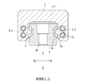
- FIG. 2 shows a cross-sectional view (a cross-sectional view taken along line II-II in FIG. 1) orthogonal to the length direction of the linear guide.
- the block body 5 has a central portion 5-1 facing the upper surface 2-1 of the guide rail 2 and a pair of leg portions 5-2 facing the side surfaces of the guide rail 2, and is formed in a U-shaped cross section.
- the end caps 3a and 3b are formed with U-shaped direction change paths that connect the load rolling element rolling portions 5a and the return path 5b.
- the rolling element circulation path is constituted by the loaded rolling element rolling part 5a, the return path 5b, and the pair of direction changing paths. A large number of rolling elements 6 are accommodated in the rolling element circulation path.
- a preload is applied to the linear guide, and the rolling element 6 sandwiched between the rolling element rolling part 2a and the load rolling element rolling part 5a is compressed.
- the block 4 is moved relative to the guide rail 2, the rolling elements 6 roll between them.
- the movement of the block 4 relative to the guide rail 2 is relative, and the block 4 may move or the guide rail 2 may move.
- a pair of cooling nozzles 1a and 1b are attached to both end faces of the block 4 in the front-rear direction.
- the cooling nozzles 1 a and 1 b have an opening 11.
- the guide rail 2 and the block 4 are cooled by blowing an air flow from the opening 11.
- the opening 11 is not disposed on the inner surface of the cooling nozzles 1a and 1b facing the guide rail 2, but on the outer surface 41 of the cooling nozzles 1a and 1b.
- Tubes 8a and 8b for supplying compressed air to the cooling nozzles 1a and 1b are connected to the cooling nozzles 1a and 1b.
- the other ends of the tubes 8a and 8b are connected to a compressor such as a compressor via a pressure regulating valve such as a pressure reducing valve. Compressed air with adjusted pressure is supplied to the cooling nozzles 1a and 1b.
- One cooling nozzle 1 a has a guide rail opening 12 for cooling the guide rail 2 and a block opening 13 for cooling the block 4, and is opposed to the guide rail 2 and the block 4. Blows airflow in the direction.
- the other cooling nozzle 1 b has only a guide rail opening 12 for cooling the guide rail 2, and blows an air flow toward only the guide rail 2. Both the cooling nozzles 1a and 1b can be provided with only the guide rail opening 12, or both the cooling nozzles 1a and 1b can be provided with the guide rail opening 12 and the block opening 13.
- FIG. 3 shows a detailed perspective view of the linear guide with the tube removed
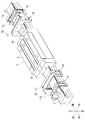
- FIG. 4 shows an exploded perspective view of the cooling nozzles 1a and 1b.
- the cooling nozzle 1a includes a central portion 1-1 facing the upper surface 2-1 of the guide rail 2 and a pair of leg portions facing the side surface 2-2 of the guide rail 2 in the same manner as the block 4. 1-2.
- the guide rail opening 12 has an upper surface side opening 12a disposed in the central portion 1-1 and a side surface side opening 12b disposed in the leg portion 1-2.
- the block opening 13 is disposed only in the leg portion 1-2.
- a table or the like is attached to the upper surface of the block 4.
- the cooling nozzle 1a is attached to the end cap 3a by a fastening member such as a screw.
- a through hole 15 for a fastening member is formed in the cooling nozzle 1a.
- the cooling nozzle 1 a includes an inner member 16 that is fitted to the guide rail 2 and an outer member 17 that is fitted to the outside of the inner member 16.
- An inner passage 18 through which air is introduced between the inner member 16 and the outer member 17, and a guide rail opening 12 that discharges an air flow toward the guide rail 2 are defined.
- the internal passage 18 is elongated in the left-right direction at the central portion 1-1 (see FIG. 3) of the cooling nozzle 1a, and is bent at both ends in the left-right direction to extend downward from the leg portion 1-2 (see FIG. 3).
- the inner member 16 and the outer member 17 are made of resin or metal.
- the inner member 16 and the outer member 17 are joined by a fastening member such as a screw.
- a screw hole 19 into which the fastening member is screwed is formed in the inner member 16, and a through hole 20 for the fastening member is formed in the outer member 17.
- FIGS. 5B and 5C show the outer member 17 (the outer member 17 is the main body portion 17a of FIG. 5B and a pair of FIG. 5C).
- a perspective view of an insert 17b) is shown.
- the inner member 16 includes a central portion 16-1 facing the upper surface 2-1 of the guide rail 2 and a pair of leg portions 16- facing the side surface 2-2 of the guide rail 2. 2 and a U-shape.
- An inner surface 16 a of the inner member 16 facing the guide rail 2 is formed in a shape that matches the outer shape of the guide rail 2.
- a groove 18 a constituting the internal passage 18 is formed on the outer surface 16 b of the inner member 16 facing the outer member 17.
- a baffle plate 24 is provided at the intersection of the inclined surface 23a of the central portion 16-1 and the inclined surface 23b of the leg portion 16-2.
- An introduction port 25 communicating with the internal passage 18 is formed in the central portion 16-1.
- the tube 8 a is connected to the introduction port 25.
- the outer member 17 has a main body portion 17a and a pair of inserts 17b fitted to the main body portion 17a.
- the main body portion 17a includes a central portion 17-1 and a pair of leg portions 17-2.
- the leg portion 17-2 has concave portions 26a and 26b at the upper and lower end portions thereof.
- the insert 17b has a pair of upper and lower convex portions 27a and 27b and a connecting portion 28 that connects the convex portions 27a and 27b.
- the convex portions 27a and 27b fit into the concave portions 26a and 26b of the leg portion 17-2.
- the insert 17b is fastened together with the main body 17a by a fastening member for joining the cooling nozzle 1a to the end cap 3a.
- the central portion 17-1 of the main body portion 17a is located on the upstream side of the guide rail opening constituting surface 31a facing the guide rail opening constituting surface 21a of the inner member 16, and on the upstream side of the guide rail opening constituting surface 31a.
- a guide surface 32a outside 17a is formed.
- the guide surface 32a is a flat surface.
- the insertion member 17b is located on the upstream side of the guide rail opening component surface 31b and the guide rail opening component surface 31a opposite to the guide rail opening component surface 21b of the inner member 16, and is located outside the guide member 17b. 32b is formed.
- the block opening 13 (see FIG. 3) provided in the leg 1-2 of the cooling nozzle 1a is configured as follows. As shown in FIGS. 5B and 5C, a block opening 13 (see FIG. 3) that discharges an air flow toward the block 4 is defined between the main body portion 17 a and the insertion body 17 b.
- the main body portion 17 a includes a block opening constituting surface 33 (details will be described later) communicating with the internal passage 18, a deflection surface 34 (details will be described later) adjacent to the downstream side of the block opening constituting surface 33, and a deflection surface 34.
- An inclined surface 35 adjacent to the downstream side is formed.
- the inclined surface 35 is a flat surface.
- the insertion member 17b is formed with a block opening component surface 36 that faces the block opening component surface 33 of the main body 17a, and an induction surface 32b that is positioned upstream of the block opening component surface 36 and outside the insert member 17b. Is done.
- the guide surface 32b serves as both the guide surface 32b of the side opening 12b (see FIG. 3) and the guide surface 32b of the block opening 13 (see FIG. 3).
- FIG. 6 is a vertical sectional view of the cooling nozzle 1a (cross-sectional view taken along the line VI-VI in FIG. 3), and FIG. 6 (b) is an enlarged view of a portion b in FIG. 6 (a).
- the upper surface side opening 12 a (see FIG. 3) is defined by the guide rail opening constituting surface 21 a of the inner member 16 and the guide rail opening constituting surface 31 a of the outer member 17.
- the upper surface side opening 12 a communicates with the internal passage 18.
- the upper surface side opening 12a is formed of a slit in which the width between the guide rail opening constituting surface 21a and the guide rail opening constituting surface 31a gradually increases from the entrance toward the exit.
- the deflection surface 22a is adjacently positioned.
- the deflection surface 22a is a curved surface having a circular cross section.
- the cross section of the deflection surface 22a can be formed in a polygon instead of an arc.
- the deflecting surface 22a sucks the air flow emitted from the upper surface side opening 12a to the surface and bends along the surface.
- a low pressure region is generated on the deflection surface 22a by the Coanda effect, and air is drawn.
- Air is drawn along the guide surface 32a.
- the drawn air flow accompanies the gas flow released from the upper surface side opening 12a.
- the amplified air flow is directed toward the upper surface 2-1 of the guide rail 2 along the inclined surface 23a.
- FIG. 7 (a) shows a horizontal sectional view of the cooling nozzle 1a (sectional view taken along line VII-VII in FIG. 3).
- the side opening 12b (see FIG. 3) is formed by the guide rail opening constituting surface 21b of the inner member 16 and the guide rail opening constituting surface 31b of the outer member 17.
- a deflecting surface 22b that bends the airflow discharged from the side surface opening 12b is located adjacently.
- a guide surface 32b that draws air is positioned adjacently.
- the amplified air flow is directed to the side surface 2-2 of the guide rail 2 along the inclined surface 23b.
- the baffle plate 24 (see FIG. 5A) separates the air flow emitted from the upper surface side opening 12a and the air flow emitted from the side surface side opening 12b.
- the block opening 13 (see FIG. 3) is defined by the block opening constituting surface 33 of the main body 17a and the block opening constituting surface 36 of the insert 17b.
- the block opening 13 communicates with the internal passage 18.
- the block opening 13 includes a slit whose width gradually decreases from the inlet toward the outlet.
- a deflection surface 34 is located adjacent to the downstream side of the block opening 13. The deflecting surface 34 sucks the air flow emitted from the block opening 13 to the surface and bends it along the surface. When the air flow is bent, the Coanda effect creates a low pressure region on the deflection surface 34 and air is drawn. Air is drawn along the guide surface 32b. The drawn air flow accompanies the gas flow discharged from the block opening 13. The amplified air flow is directed to the side surface of the block 4 along the inclined surface 35.
- the configuration of the remaining one cooling nozzle 1b is as follows. 8A shows the inner member 16 of the cooling nozzle 1b, and FIG. 8B shows the outer member 17 of the cooling nozzle 1b.
- the cooling nozzle 1a and the cooling nozzle 1b differ depending on whether or not the block opening 13 is provided. As shown in FIG. 8B, the outer member 17 of the cooling nozzle 1b is not provided with the block opening 13. Since other configurations are the same as those of the cooling nozzle 1a, the same reference numerals are given and description thereof is omitted.
- FIG. 9A shows a horizontal sectional view of the cooling nozzle 1b (cross sectional view taken along the line IX-IV in FIG. 3).
- the side opening 12b is defined by the guide rail opening constituting surface 21b of the inner member 16 and the guide rail opening constituting surface 31b of the outer member 17.
- a deflecting surface 22b that bends the airflow discharged from the side surface opening 12b is located adjacently.
- An inclined surface 23b is positioned adjacent to the downstream side of the deflection surface 22b.
- An induction surface 32b that draws air into the outer surface of the outer member 17 is positioned adjacent to the upstream side of the side surface opening 12b.
- the tube 8a is connected to the inlet 25 of the cooling nozzle 1a, and compressed air is introduced into the inlet 25 (see (1) input in FIG. 10).
- the air flow introduced into the introduction port 25 branches the internal passage 18 in the left-right direction and fills the internal passage 18 (indicated by a broken line in FIG. 10).
- the air flow enters the guide rail opening 12 and the block opening 13 which are continuous with the internal passage 18, and is accelerated and discharged from the guide rail opening 12 and the block opening 13 as a primary air flow (FIG. 10). Arrow (2)).
- the primary air flow (2) discharged from the guide rail opening 12 is directed onto the deflection surface 22a.
- the primary air flow (2) flows along the deflection surface 22a and is bent by the deflection surface 22a. Since a low pressure region is generated on the deflection surface 22a due to the Coanda effect, a secondary air flow indicated by an arrow (3) in the drawing is drawn through the guide surface 32a.
- the secondary air flow (3) is accompanied by the primary air flow (2) and amplifies the primary air flow (2).
- the amplified air flow is indicated by arrow (4).
- the amplified air flow (4) is guided to the guide rail 2 along the inclined surface 23a.
- the primary air flow (2) exiting from the block opening 13 also flows along the deflection surface 34 and is bent by the deflection surface 34. Since a low pressure region is generated on the deflection surface 34 due to the Coanda effect, the secondary air flow indicated by the arrow (5) in the drawing is drawn through the guide surface 32b.
- the secondary air flow (5) is accompanied by the primary air flow (2) and amplifies the primary air flow (2).
- the amplified air flow is guided to the block 4 along the inclined surface 35.
- the following effects are further achieved. Since the cooling nozzles 1 a and 1 b can be easily attached to the block 4 as an option, the cooling nozzles 1 a and 1 b can be used regardless of the length or type of the guide rail 2.
- both the guide rail 2 and the block 4 can be cooled.
- the openings 12, 13 of the cooling nozzles 1a, 1b are not arranged on the inner surfaces of the cooling nozzles 1a, 1b facing the guide rail 2, but are arranged on the outer surface 41 of the cooling nozzles 1a, 1b. It is possible to draw in air in a wide space outside of the guide rail 2 and to concentrate the air flow on the guide rail 2.
- the guide rail opening 12 has an upper surface side opening 12a disposed in the central portion 1-1 of the cooling nozzles 1a and 1b and a side surface opening 12b disposed in the leg portion 1-2, the guide rail 2 An air flow can be blown to the upper surface 2-1 and the side surface 2-2.
- cooling nozzles 1a and 1b have the baffle plate 24 that separates the air flow discharged from the upper surface side opening 12a and the air flow discharged from the side surface side opening 12b, the air flow discharged from the upper surface side opening 12a and the side surface It is possible to prevent the airflows discharged from the side openings 12b from mixing with each other and inhibiting the flow of each other's airflows.
- the cooling efficiency of the guide rail 2 and the block 4 is improved by providing the guide rail opening 12 and the block opening 13 in one cooling nozzle 1a and providing only the guide rail opening 12 in the other cooling nozzle 1b. Can do. If the block openings 13 are provided in both the cooling nozzles 1a and 1b, the flow of the air flow collides with the center in the front-rear direction of the block 4, but the block openings 13 are provided only in one of the cooling nozzles 1a. This can be avoided. Moreover, the air flow blown from one cooling nozzle 1a toward the block 4 is guided to the guide rail 2 along with the air flow blown from the guide rail opening 12 of the other cooling nozzle 1b. Therefore, the cooling efficiency of the guide rail 2 can be improved.
- movement guide apparatus of this invention is not limited to the said embodiment, It can embody in other embodiment in the range which does not change the summary of this invention.
- a linear guide is used as the motion guide device, but a ball spline or a ball bush can also be used.
- the configuration of the cooling nozzle of the above embodiment is an example, and other configurations can be employed without changing the gist of the present invention.
- air is used as the gas, but nitrogen gas, halogen gas, or the like can also be used.
- a mist-like liquid can be mixed in the gas flow.
Landscapes
- Engineering & Computer Science (AREA)
- General Engineering & Computer Science (AREA)
- Mechanical Engineering (AREA)
- Bearings For Parts Moving Linearly (AREA)
- Mounting Of Bearings Or Others (AREA)
Abstract
運動案内装置を気体冷却することができる運動案内装置用冷却ノズルを提供する。 本発明の冷却ノズル1a,1bは、運動案内装置のブロック4に装着されて、案内レール2及びこの案内レール2に転動体6を介して相対移動可能に組み付けられるブロック4の少なくとも一方を冷却する。冷却ノズル1a,1bは、気体が導入される内部通路18と、内部通路18に導入された気体流を放出させる開口12aと、開口12aに隣接して設けられ、開口12aから放出される気体流を曲げる偏向面22aと、冷却ノズル1a,1bの外側の気体を引き込む誘導面32aと、を有する。
Description
本発明は、案内レールに転動体を介してブロックが相対移動可能に組み付けられる運動案内装置を冷却するための運動案内装置用冷却ノズル、冷却ノズル付き運動案内装置及び運動案内装置用冷却システムに関する。
例えば工作機械のテーブルの運動を案内する運動案内装置が知られている。運動案内装置は、案内レールと、案内レールにボール、ローラ等の多数の転動体を介して相対移動可能に組み付けられるブロックと、を備える。テーブルはボールねじ、リニアモータ等の駆動装置によって駆動される。テーブルの運動は運動案内装置によって案内される。転動体の転がり運動を利用してテーブルの運動を案内することで、テーブルの軽快な動きが得られる。
剛性を高めるために、運動案内装置には予圧、すなわち案内レールとブロックとで挟まれる転動体の荷重が付与される。また、ブロックにはシール部材が装着される。このため、運動案内装置には摩擦が存在する。運動案内装置を高負荷及び/又は高速で作動させると、摩擦が原因で運動案内装置が発熱する。この発熱は、レール及びブロックを熱膨張させてテーブルの送り精度の低下を招いたり、レール及びブロックが取り付けられる構成部品を熱膨張させたりする。高精度でテーブルを移動させるために、運動案内装置の冷却が必要になる。
従来の運動案内装置として、特許文献1には、運動案内装置の案内レールに冷却水用の溝を形成し、この溝に冷却水を供給し、案内レールを冷却した運動案内装置が開示されている。特許文献2には、運動案内装置のブロックに冷却水用の通路を形成し、この通路に冷却水を供給し、ブロックを冷却した運動案内装置が開示されている。
しかし、従来の運動案内装置にあっては、案内レール及び/又はブロックに冷却水用の溝及び/又は通路を加工するのが困難であり、また、冷却水の漏れを防ぐ必要があるので、そのためのシール機構が必要になるという課題がある。運動案内装置を空冷することができれば、この課題を解決することができるが、液体冷却に比べて冷却効率が低いという新たな課題が生ずる。
そこで本発明は、運動案内装置を気体冷却することができる運動案内装置用冷却ノズル、冷却ノズル付き運動案内装置及び運動案内装置用冷却システムを提供することを目的とする。
本発明の一態様は、案内レール及びこの案内レールに転動体を介して相対移動可能に組み付けられるブロックの少なくとも一方を冷却するための運動案内装置用冷却ノズルであって、前記冷却ノズルは、気体が導入される内部通路と、前記内部通路に導入された気体流を放出させる開口と、前記開口に隣接して設けられ、前記開口から放出される気体流を曲げる偏向面と、前記冷却ノズルの外側の気体を引き込む誘導面と、を有する運動案内装置用冷却ノズルにより上述した課題を解決する。
本発明によれば、冷却ノズルの開口から放出される気体流は偏向面に沿って曲げられる。気体流が曲げられると、コアンダ効果によって偏向面上には低圧領域が生じ、冷却ノズル外側の気体が誘導面を経由して引き込まれる。誘導面を経由して引き込まれた気体流は、開口から放出される気体流に同伴するので、開口から放出される気体流が増幅される。この増幅された気体流で案内レール及び/又はブロックを冷却することで、気体冷却であっても、運動案内装置を効果的に冷却することができる。
以下、添付図面を参照して、本発明の冷却ノズルの実施形態を説明する。ただし、本発明の冷却ノズルは種々の形態で具体化することができ、明細書に記載される実施形態に限定されるものではない。本実施形態は明細書の開示を十分にすることによって、当業者が発明の範囲を十分に理解できるようにする意図をもって提供されるものである。
図1は、本発明の実施形態の冷却ノズル1a,1bが取り付けられたリニアガイドの斜視図を示す。以下においては、水平面に配置した案内レール2を長さ方向から見たときの各方向、すなわち図1に示す左右方向、上下方向及び前後方向を用いてリニアガイドの構成を説明する。もちろん、リニアガイドの配置は、このような左右、上下及び前後に限定されるものではない。また、図面及び明細書を通して同一の構成には同一の符号を附す。
図1に示すように、リニアガイドは、前後方向に細長い案内レール2と、案内レール2に前後方向に移動可能に組み付けられるブロック4と、を備える。リニアガイドの案内レール2及びブロック4は周知のものである。案内レール2には、ボール、ローラ等の転動体が転がり運動する複数条の転動体転走部2aが長さ方向に沿って形成される。案内レール2は、上面2-1、左右一対の側面2-2、及び底面2-3を有する。案内レール2の上面2-1には、案内レール2を相手部品に取り付けるためのボルト挿入孔2bが長さ方向に一定のピッチで形成される。
ブロック4は案内レール2に跨るように案内レール2に組み付けられる。ブロック4は、ブロック本体5と、ブロック本体5の前後方向の両端面に取り付けられる一対のエンドキャップ3a,3bと、を備える。エンドキャップ3a,3bの端面には、必要に応じてエンドシール、潤滑剤供給装置等のオプションが取り付けられる。
図2はリニアガイドの長さ方向に直交する断面図(図1のII-II線断面図)を示す。ブロック本体5は、案内レール2の上面2-1に対向する中央部5-1と、案内レール2の側面に対向する一対の脚部5-2を有して、断面コの字形に形成される。ブロック本体5の内面には、案内レール2の転動体転走部2aに対向する負荷転動体転走部5a、及び負荷転動体転走部5aに平行な戻し路5bが形成される。エンドキャップ3a,3bには、負荷転動体転走部5aと戻し路5bを接続するU字形の方向転換路が形成される。
負荷転動体転走部5a、戻し路5b、一対の方向転換路によって転動体循環路が構成される。転動体循環路には多数の転動体6が収容される。リニアガイドの剛性を高めるために、リニアガイドには予圧が付与され、転動体転走部2aと負荷転動体転走部5aとに挟まれる転動体6が圧縮される。案内レール2に対してブロック4を相対的に移動させると、転動体6がこれらの間で転がり運動する。なお、案内レール2に対するブロック4の移動は相対的なものであり、ブロック4が移動することも、案内レール2が移動することもある。
図1に示すように、ブロック4の前後方向の両端面には、一対の冷却ノズル1a,1bが取り付けられる。冷却ノズル1a,1bは開口11を有する。開口11から空気流を吹き出すことで、案内レール2及びブロック4を冷却する。開口11は、案内レール2に対向する冷却ノズル1a,1bの内面ではなく、冷却ノズル1a,1bの外面41に配置される。冷却ノズル1a,1bには、冷却ノズル1a,1bに圧縮空気を供給するチューブ8a,8bが接続される。チューブ8a,8bの他端は減圧弁等の圧力調整弁を介してコンプレッサ等の圧縮機に接続される。冷却ノズル1a,1bには圧力が調整された圧縮空気が供給される。
一方の冷却ノズル1aは、案内レール2を冷却するための案内レール用開口12と、ブロック4を冷却するためのブロック用開口13と、を有し、案内レール2及びブロック4に向かって相反する方向に空気流を吹き出す。もう一方の冷却ノズル1bは、案内レール2を冷却するための案内レール用開口12のみを有し、案内レール2のみに向かって空気流を吹き出す。なお、両方の冷却ノズル1a,1bに案内レール用開口12のみを設けることも、両方の冷却ノズル1a,1bに案内レール用開口12及びブロック用開口13を設けることも可能である。
図3はチューブを取り外したリニアガイドの詳細な斜視図を示し、図4は冷却ノズル1a,1bの分解斜視図を示す。まず、一方の冷却ノズル1aの構成を説明する。図3に示すように、冷却ノズル1aは、ブロック4と同様に案内レール2の上面2-1に対向する中央部1-1と、案内レール2の側面2-2に対向する一対の脚部1-2と、を有してコ字形である。案内レール用開口12は、中央部1-1に配置される上面側開口12aと、脚部1-2に配置される側面側開口12bと、を有する。ブロック用開口13は、脚部1-2にのみ配置される。ブロック4の上面にはテーブル等が取り付けられている。ブロック用開口13を脚部1-2に配置することで、ブロック4を冷却することができる。冷却ノズル1aは、ねじ等の締結部材によってエンドキャップ3aに取り付けられる。冷却ノズル1aには締結部材の通し孔15が形成される。
図4に示すように、冷却ノズル1aは、案内レール2に嵌められる内側部材16と、内側部材16の外側に嵌められる外側部材17と、を備える。内側部材16と外側部材17との間に空気が導入される内部通路18、及び案内レール2に向かって空気流を放出する案内レール用開口12が画定される。内部通路18は、冷却ノズル1aの中央部1-1(図3参照)を左右方向に細長く延び、左右方向の両端部で折れ曲って脚部1-2(図3参照)を下方向に延びる。内側部材16及び外側部材17は樹脂又は金属製である。内側部材16と外側部材17とはねじ等の締結部材で接合される。内側部材16には締結部材が螺合するねじ孔19が形成され、外側部材17には締結部材の通し孔20が形成される。
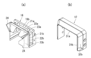
図5(a)は内側部材16の斜視図を示し、図5(b)(c)は外側部材17(外側部材17は図5(b)の本体部17a及び図5(c)の一対の挿入体17bから構成される)の斜視図を示す。図5(a)に示すように、内側部材16は、案内レール2の上面2-1に対向する中央部16-1と、案内レール2の側面2-2に対向する一対の脚部16-2と、を有してコ字形である。案内レール2に対向する内側部材16の内面16aは、案内レール2の外形に合わせた形状に形成される。外側部材17に対向する内側部材16の外面16bには、内部通路18を構成する溝18aが形成される。
内側部材16の外面16bには、さらに内部通路18に連通する案内レール用開口構成面21a,21b(詳しくは後述する)、案内レール用開口構成面21a,21bの下流側に隣接する偏向面22a,22b(詳しくは後述する)、偏向面22a,22bの下流側に隣接する傾斜面23a,23bが形成される。傾斜面23a,23bは平面からなる。傾斜面23a,23bは、案内レール2の上面2-1又は側面2-2(図1参照)に対して鋭角に傾けられる。中央部16-1の傾斜面23aと脚部16-2の傾斜面23bとの交差部には、バッフル板24が設けられる。中央部16-1には、内部通路18に連通する導入口25が形成される。導入口25にチューブ8aが接続される。
図5(b)(c)に示すように、外側部材17は、本体部17aと、本体部17aに嵌められる一対の挿入体17bと、を有する。本体部17aは内側部材16と同様に、中央部17-1と、一対の脚部17-2と、を有する。脚部17-2はその上下端部に凹部26a,26bを有する。挿入体17bは、上下一対の凸部27a,27bと、凸部27a,27bを連結する連結部28と、を有する。この凸部27a,27bが脚部17-2の凹部26a,26bに嵌まる。挿入体17bは、冷却ノズル1aをエンドキャップ3aに接合するための締結部材によって本体部17aに共締めされる。
本体部17aの中央部17-1には、内側部材16の案内レール用開口構成面21aに対向する案内レール用開口構成面31a、案内レール用開口構成面31aの上流側に位置し、本体部17aの外側の誘導面32aが形成される。誘導面32aは平面からなる。挿入体17bには、内側部材16の案内レール用開口構成面21bに対向する案内レール用開口構成面31b、案内レール用開口構成面31aの上流側に位置し、挿入体17bの外側の誘導面32bが形成される。
冷却ノズル1aの脚部1-2に設けられるブロック用開口13(図3参照)は、以下のように構成される。図5(b)(c)に示すように、本体部17aと挿入体17bとの間に、ブロック4に向かって空気流を放出するブロック用開口13(図3参照)が画定される。本体部17aには、内部通路18に連通するブロック用開口構成面33(詳しくは後述する)、ブロック用開口構成面33の下流側に隣接する偏向面34(詳しくは後述する)、偏向面34の下流側に隣接する傾斜面35が形成される。傾斜面35は平面からなる。挿入体17bには、本体部17aのブロック用開口構成面33に対向するブロック用開口構成面36、ブロック用開口構成面36の上流側に位置し、挿入体17bの外側の誘導面32bが形成される。誘導面32bは、側面側開口12b(図3参照)の誘導面32bとブロック用開口13(図3参照)の誘導面32bとを兼用している。
図6は冷却ノズル1aの垂直断面図(図3のVI-VI線断面図)を示し、図6(b)は図6(a)のb部拡大図を示す。図6(b)に示すように、上面側開口12a(図3参照)は、内側部材16の案内レール用開口構成面21aと外側部材17の案内レール用開口構成面31aによって画定される。上面側開口12aは内部通路18に連通する。上面側開口12aは、入口から出口に向かって案内レール用開口構成面21aと案内レール用開口構成面31aとの間の幅が徐々に広くなるスリットからなる。上面側開口12aの下流側には、偏向面22aが隣接して位置する。偏向面22aは、断面が円弧の曲面からなる。偏向面22aの断面を円弧の替わりに多角形に形成することもできる。偏向面22aは、上面側開口12aから放出される空気流を表面に吸い付け、表面に沿って曲げる。空気流が曲げられると、コアンダ効果によって偏向面22a上に低圧領域が生じ、空気が引き込まれる。空気は誘導面32aに沿って引き込まれる。引き込まれた空気流は、上面側開口12aから放出される気体流に同伴する。増幅された空気流は、傾斜面23aに沿って案内レール2の上面2-1に向かう。
図7(a)は、冷却ノズル1aの水平断面図(図3のVII-VII線断面図)を示す。図7(b)のb部拡大図に示すように、側面側開口12b(図3参照)は、内側部材16の案内レール用開口構成面21bと外側部材17の案内レール用開口構成面31bによって画定される。側面側開口12bの下流側には、側面側開口12bから放出される空気流を曲げる偏向面22bが隣接して位置する。側面側開口12bの上流側には、空気を引き込む誘導面32bが隣接して位置する。増幅された空気流は、傾斜面23bに沿って案内レール2の側面2-2に向かう。バッフル板24(図5(a)参照)は、上面側開口12aから放出される空気流と側面側開口12bから放出される空気流を分離させる。
図7(b)に示すように、ブロック用開口13(図3参照)は、本体部17aのブロック用開口構成面33と挿入体17bのブロック用開口構成面36とによって画定される。ブロック用開口13は内部通路18に連通する。ブロック用開口13は、入口から出口に向かって幅が徐々に狭くなるスリットからなる。ブロック用開口13の下流側には、偏向面34が隣接して位置する。偏向面34は、ブロック用開口13から放出される空気流を表面に吸い付け、表面に沿って曲げる。空気流が曲げられると、コアンダ効果によって偏向面34上に低圧領域が生じ、空気が引き込まれる。空気は、誘導面32bに沿って引き込まれる。引き込まれた空気流は、ブロック用開口13から放出される気体流に同伴する。増幅された空気流は、傾斜面35に沿ってブロック4の側面に向かう。
残りの一方の冷却のノズル1bの構成は以下の通りである。図8(a)は冷却ノズル1bの内側部材16を示し、図8(b)は冷却ノズル1bの外側部材17を示す。冷却ノズル1aと冷却ノズル1bとは、ブロック用開口13を有するか否かで相違する。図8(b)に示すように、冷却ノズル1bの外側部材17には、ブロック用開口13が設けられていない。他の構成は冷却ノズル1aと同一なので、同一の符号を附してその説明を省略する。
図9(a)は冷却ノズル1bの水平断面図(図3のIX- IX線断面図)を示す。図9(b)のb部拡大図に示すように、側面側開口12bは、内側部材16の案内レール用開口構成面21bと外側部材17の案内レール用開口構成面31bによって画定される。側面側開口12bの下流側には、側面側開口12bから放出される空気流を曲げる偏向面22bが隣接して位置する。偏向面22bの下流側には傾斜面23bが隣接して位置する。側面側開口12bの上流側には、外側部材17の外面に空気を引き込む誘導面32bが隣接して位置する。
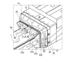
図10を参照しつつ冷却システムの動作を説明する。まず、冷却ノズル1aの導入口25にチューブ8aを接続し、導入口25に圧縮空気を導入する(図10の(1)入力参照)。導入口25に導入された空気流は、内部通路18を左右方向に分岐し、内部通路18内に充満する(図10中破線で示す)。
次に、空気流は、内部通路18に連続する案内レール用開口12及びブロック用開口13に入り、加速されて一次空気流として案内レール用開口12及びブロック用開口13から放出される(図10の矢印(2)参照)。
案内レール用開口12から放出された一次空気流(2)は、偏向面22a上に向けられる。一次空気流(2)は、偏向面22aに沿いながら流れ、偏向面22aによって曲げられる。偏向面22a上には、コアンダ効果によって低圧領域が生ずるので、図中矢印(3)で示す二次空気流が誘導面32aを経由して引き込まれる。二次空気流(3)は、一次空気流(2)に同伴し、一次空気流(2)を増幅させる。増幅された空気流を矢印(4)で示す。増幅された空気流(4)は、傾斜面23aに沿って案内レール2に導かれる。この増幅された空気流(4)で案内レール2を冷却することで、気体冷却であっても、運動案内装置を効果的に冷却することができる。
ブロック用開口13から出た一次空気流(2)も、偏向面34に沿いながら流れ、偏向面34によって曲げられる。偏向面34上には、コアンダ効果によって低圧領域が生ずるので、図中矢印(5)で示す二次空気流が誘導面32bを経由して引き込まれる。二次空気流(5)は、一次空気流(2)に同伴し、一次空気流(2)を増幅させる。増幅された空気流は、傾斜面35に沿ってブロック4に導かれる。
本実施形態の冷却ノズルによれば、さらに以下の効果を奏する。ブロック4にオプションとして冷却ノズル1a,1bを簡単に取り付けることができるので、案内レール2の長さ又は種類によらず冷却ノズル1a,1bを使用することができる。
冷却ノズル1a,1bに案内レール用開口12とブロック用開口13を設けるので、案内レール2とブロック4の両方を冷却することができる。
冷却ノズル1a,1bの開口12,13が案内レール2に対向する冷却ノズル1a,1bの内面に配置されることなく、冷却ノズル1a,1bの外面41に配置されるので、冷却ノズル1a,1bの外側の広い空間の空気を引き込むことができ、また案内レール2に集中的に空気流を当てることができる。
案内レール用開口12が、冷却ノズル1a,1bの中央部1-1に配置される上面側開口12aと、脚部1-2に配置される側面側開口12bと、を有するので、案内レール2の上面2-1及び側面2-2に空気流を吹き出すことができる。
冷却ノズル1a,1bが、上面側開口12aから放出される空気流と側面側開口12bから放出される空気流を分離させるバッフル板24を有するので、上面側開口12aから放出される空気流と側面側開口12bから放出される空気流とが混ざり合い、互いの空気流の流れを阻害するのを防止することができる。
一方の冷却ノズル1aに案内レール用開口12及びブロック用開口13を設け、もう一方の冷却ノズル1bに案内レール用開口12のみを設けることで、案内レール2及びブロック4の冷却効率を向上させることができる。もし、両方の冷却ノズル1a,1bにブロック用開口13を設けると、ブロック4の前後方向の中央で空気流の流れが衝突するが、一方の冷却ノズル1aにのみブロック用開口13を設けることで、これを回避することができる。しかも、一方の冷却ノズル1aからブロック4に向かって吹き出された空気流がもう一方の冷却ノズル1bの案内レール用開口12から吹き出された空気流に同伴して、案内レール2に導かれる。したがって、案内レール2の冷却効率を向上させることができる。
なお、本発明の運動案内装置は、上記実施形態に限定されるものではなく、本発明の要旨を変更しない範囲で他の実施形態に具現化できる。例えば、上記実施形態では、運動案内装置としてリニアガイドを用いているが、ボールスプライン、ボールブッシュを用いることもできる。
上記実施形態の冷却ノズルの構成は一例であり、本発明の要旨を変更しない範囲で他の構成を採用することができる。
また、上記実施形態では、気体として空気を用いているが、窒素ガス、ハロゲンガス等を用いることもできる。気体流に霧状の液体を混在させることもできる。
本明細書は、2014年12月25日出願の特願2014-262952に基づく。この内容はすべてここに含めておく。
1a,1b…冷却ノズル,2…案内レール,2a…転動体転走部,3a,3b…エンドキャップ,4…ブロック,5…ブロック本体,5a…負荷転動体転走部,5b…戻し路,6…転動体,8a,8b…チューブ,11…開口,12…案内レール用開口(開口),13…ブロック用開口(開口),12a…上面側開口(案内レール用開口),12b…側面側開口(案内レール用開口),16…内側部材,17…外側部材,17a…本体部,17b…挿入体,18…内部通路,21a,21b…案内レール用開口構成面,22a,22b…偏向面,23a,23b…傾斜面,24…バッフル板,25…導入口,31a,31b…案内レール用開口構成面,32a,32b…誘導面,33…ブロック用開口構成面,34…偏向面,35…傾斜面,36…ブロック用開口構成面,41…冷却ノズルの外面
Claims (9)
- 案内レール及びこの案内レールに転動体を介して相対移動可能に組み付けられるブロックの少なくとも一方を冷却するための運動案内装置用冷却ノズルであって、
前記冷却ノズルは、気体が導入される内部通路と、前記内部通路に導入された気体流を放出させる開口と、前記開口に隣接して設けられ、前記開口から放出される気体流を曲げる偏向面と、前記冷却ノズルの外側の気体を引き込む誘導面と、を有する運動案内装置用冷却ノズル。 - 前記冷却ノズルは、前記ブロックに取り付けられることを特徴とする請求項1に記載の運動案内装置用冷却ノズル。
- 前記開口は、前記案内レールを冷却するための案内レール用開口と、前記ブロックを冷却するためのブロック用開口と、を有することを特徴とする請求項2に記載の運動案内装置用冷却ノズル。
- 前記開口は、前記案内レールに対向する前記冷却ノズルの内面に配置されることなく、前記冷却ノズルの外面に配置されることを特徴とする請求項1ないし3のいずれか1項に記載の運動案内装置用冷却ノズル。
- 前記冷却ノズルは、前記偏向面に隣接して設けられ、前記開口から放出される気体流を前記案内レール及び前記ブロックの少なくとも一方に導く傾斜面を有することを特徴とする請求項1ないし4のいずれか1項に記載の運動案内装置用冷却ノズル。
- 前記冷却ノズルは、前記案内レールの上面に対向する中央部と、前記案内レールの側面に対向する脚部と、を有し、
前記開口は、前記案内レールを冷却するための案内レール用開口を有し、
前記案内レール用開口は、前記中央部に配置される上面側開口と、前記脚部に配置される側面側開口と、を有することを特徴とする請求項1ないし5のいずれか1項に記載の運動案内装置用冷却ノズル。 - 前記冷却ノズルは、前記上面側開口から放出される気体流と前記側面側開口から放出される気体流を分離させるバッフル板を有することを特徴とする請求項6に記載の運動案内装置用冷却ノズル。
- 請求項1ないし7のいずれかに記載の運動案内装置用冷却ノズルと、
前記運動案内装置と、を備える冷却ノズル付き運動案内装置。 - 請求項1ないし7のいずれかに記載の運動案内装置用冷却ノズルと、
前記冷却ノズルの前記内部通路に気体を導入する手段と、を備える運動案内装置用冷却システム。
Priority Applications (3)
| Application Number | Priority Date | Filing Date | Title |
|---|---|---|---|
| US15/533,469 US9937506B2 (en) | 2014-12-25 | 2015-12-15 | Motion guide apparatus cooling nozzles, motion guide apparatus with cooling nozzles, and motion guide apparatus cooling system |
| CN201580068956.8A CN107002749B (zh) | 2014-12-25 | 2015-12-15 | 运动引导装置用冷却喷嘴、带冷却喷嘴的运动引导装置以及运动引导装置用冷却系统 |
| DE112015005783.8T DE112015005783B4 (de) | 2014-12-25 | 2015-12-15 | Kühldüsen für Bewegungsführungsvorrichtung, Bewegungsführungsvorrichtung mit Kühldüsen und Kühlsystem für Bewegungsführungsvorrichtung |
Applications Claiming Priority (2)
| Application Number | Priority Date | Filing Date | Title |
|---|---|---|---|
| JP2014-262952 | 2014-12-25 | ||
| JP2014262952A JP6008934B2 (ja) | 2014-12-25 | 2014-12-25 | 運動案内装置用冷却ノズル、冷却ノズル付き運動案内装置及び運動案内装置用冷却システム |
Publications (1)
| Publication Number | Publication Date |
|---|---|
| WO2016104233A1 true WO2016104233A1 (ja) | 2016-06-30 |
Family
ID=56150258
Family Applications (1)
| Application Number | Title | Priority Date | Filing Date |
|---|---|---|---|
| PCT/JP2015/085011 Ceased WO2016104233A1 (ja) | 2014-12-25 | 2015-12-15 | 運動案内装置用冷却ノズル、冷却ノズル付き運動案内装置及び運動案内装置用冷却システム |
Country Status (6)
| Country | Link |
|---|---|
| US (1) | US9937506B2 (ja) |
| JP (1) | JP6008934B2 (ja) |
| CN (1) | CN107002749B (ja) |
| DE (1) | DE112015005783B4 (ja) |
| TW (1) | TWI605208B (ja) |
| WO (1) | WO2016104233A1 (ja) |
Families Citing this family (4)
| Publication number | Priority date | Publication date | Assignee | Title |
|---|---|---|---|---|
| USD875150S1 (en) * | 2017-05-31 | 2020-02-11 | Thk Co., Ltd. | End plate for motion guide device |
| US10247238B1 (en) * | 2018-03-28 | 2019-04-02 | Guy R. Chaifetz | Sliding track assembly |
| CN108547866B (zh) * | 2018-07-06 | 2023-07-21 | 南京工艺装备制造有限公司 | 一种自清洁型滚动直线导轨副 |
| DE202022002593U1 (de) * | 2022-12-06 | 2024-03-07 | Nsh Technology Gmbh | Einrichtung zur Kühlung und thermischen Stabilisierung einer Profilschienenführung an einer Werkzeugmaschine |
Citations (3)
| Publication number | Priority date | Publication date | Assignee | Title |
|---|---|---|---|---|
| JP2002372119A (ja) * | 2001-06-12 | 2002-12-26 | Nsk Ltd | ボールねじ装置 |
| WO2005077597A1 (ja) * | 2004-02-18 | 2005-08-25 | Horkos Corporation | 工作機械の直動案内装置 |
| JP2012233522A (ja) * | 2011-04-28 | 2012-11-29 | Nsk Ltd | リニアガイド装置の冷却構造 |
Family Cites Families (8)
| Publication number | Priority date | Publication date | Assignee | Title |
|---|---|---|---|---|
| JP2006226402A (ja) | 2005-02-17 | 2006-08-31 | Fanuc Ltd | 直動軸受の防塵構造 |
| DE102005029854B4 (de) | 2005-06-27 | 2009-04-16 | P & L Gmbh & Co. Kg | Linearführungsschiene für ein Linearführungssystem |
| TW200827086A (en) | 2006-12-28 | 2008-07-01 | Hiwin Tech Corp | Cooling device of linear module |
| JP4869392B2 (ja) * | 2009-10-07 | 2012-02-08 | Thk株式会社 | リニアモータアクチュエータ |
| DE202010016616U1 (de) * | 2010-12-15 | 2011-02-17 | Deckel Maho Seebach Gmbh | Führungssystem für Werkzeugmaschinen |
| CN102032269A (zh) | 2010-12-29 | 2011-04-27 | 南京工艺装备制造有限公司 | 液冷滚动导轨副 |
| CN203214611U (zh) | 2013-03-22 | 2013-09-25 | 常州市中锐达精密机械有限公司 | 便于冷却的直线导轨 |
| JP5877890B2 (ja) * | 2014-07-18 | 2016-03-08 | Thk株式会社 | ねじ装置用冷却ノズル及び運動案内装置用冷却ノズル |
-
2014
- 2014-12-25 JP JP2014262952A patent/JP6008934B2/ja active Active
-
2015
- 2015-12-15 WO PCT/JP2015/085011 patent/WO2016104233A1/ja not_active Ceased
- 2015-12-15 US US15/533,469 patent/US9937506B2/en active Active
- 2015-12-15 DE DE112015005783.8T patent/DE112015005783B4/de active Active
- 2015-12-15 CN CN201580068956.8A patent/CN107002749B/zh active Active
- 2015-12-25 TW TW104143804A patent/TWI605208B/zh active
Patent Citations (3)
| Publication number | Priority date | Publication date | Assignee | Title |
|---|---|---|---|---|
| JP2002372119A (ja) * | 2001-06-12 | 2002-12-26 | Nsk Ltd | ボールねじ装置 |
| WO2005077597A1 (ja) * | 2004-02-18 | 2005-08-25 | Horkos Corporation | 工作機械の直動案内装置 |
| JP2012233522A (ja) * | 2011-04-28 | 2012-11-29 | Nsk Ltd | リニアガイド装置の冷却構造 |
Also Published As
| Publication number | Publication date |
|---|---|
| JP6008934B2 (ja) | 2016-10-19 |
| CN107002749B (zh) | 2018-06-22 |
| JP2016121787A (ja) | 2016-07-07 |
| DE112015005783B4 (de) | 2019-02-07 |
| US9937506B2 (en) | 2018-04-10 |
| TW201638486A (zh) | 2016-11-01 |
| CN107002749A (zh) | 2017-08-01 |
| TWI605208B (zh) | 2017-11-11 |
| DE112015005783T5 (de) | 2017-09-07 |
| US20170341092A1 (en) | 2017-11-30 |
Similar Documents
| Publication | Publication Date | Title |
|---|---|---|
| JP6008934B2 (ja) | 運動案内装置用冷却ノズル、冷却ノズル付き運動案内装置及び運動案内装置用冷却システム | |
| JP5877890B2 (ja) | ねじ装置用冷却ノズル及び運動案内装置用冷却ノズル | |
| EP2713118A2 (en) | Vortex tube | |
| US10837289B2 (en) | Gas turbine blade | |
| JP2014104579A (ja) | 切削インサート | |
| US10174960B2 (en) | Steam dispersion system | |
| US20180051578A1 (en) | Gas turbine transition duct | |
| JP2009502618A (ja) | 熱交換器、推進装置、及びかかる推進装置を装備した航空機 | |
| US6413470B1 (en) | Device for guiding bands in a suspended manner | |
| JPWO2017175311A1 (ja) | 連続焼鈍炉における冷却設備 | |
| FI103904B (fi) | Menetelmä ja laite ilman syöttämiseksi tulipesään | |
| US11946696B2 (en) | End barrier box and a reflow oven using the end barrier box | |
| JP2020114716A (ja) | 航空機の空調ダクト構造、航空機、および航空機の製造方法 | |
| JP6028578B2 (ja) | 燃焼器 | |
| KR20170006492A (ko) | 충돌형 온도균일화 장치 | |
| US9631505B2 (en) | Device for cooling a wall of a component | |
| JP2014214643A (ja) | 冷却装置 | |
| JP6071375B2 (ja) | 車両用空気調和装置 | |
| JP7856935B2 (ja) | 吹出ユニット | |
| KR102869270B1 (ko) | 차량용 공조장치의 블로워 장치 | |
| TH2301007285A (th) | โมดูลการผสมที่ใช้สำหรับอุปกรณ์จัดเตรียมสารทำความเย็น | |
| JP2015217424A (ja) | 複合溶接装置 | |
| JP2019135379A (ja) | 車両用送風システム | |
| CZ25947U1 (cs) | Chladicí zařízení pro chlazení trysky plazmového hořáku a plazmový hořák |
Legal Events
| Date | Code | Title | Description |
|---|---|---|---|
| 121 | Ep: the epo has been informed by wipo that ep was designated in this application |
Ref document number: 15872802 Country of ref document: EP Kind code of ref document: A1 |
|
| WWE | Wipo information: entry into national phase |
Ref document number: 15533469 Country of ref document: US |
|
| WWE | Wipo information: entry into national phase |
Ref document number: 112015005783 Country of ref document: DE |
|
| 122 | Ep: pct application non-entry in european phase |
Ref document number: 15872802 Country of ref document: EP Kind code of ref document: A1 |