WO2016104084A1 - タッチパネルユニット - Google Patents
タッチパネルユニット Download PDFInfo
- Publication number
- WO2016104084A1 WO2016104084A1 PCT/JP2015/083881 JP2015083881W WO2016104084A1 WO 2016104084 A1 WO2016104084 A1 WO 2016104084A1 JP 2015083881 W JP2015083881 W JP 2015083881W WO 2016104084 A1 WO2016104084 A1 WO 2016104084A1
- Authority
- WO
- WIPO (PCT)
- Prior art keywords
- touch panel
- panel unit
- information terminal
- bezel cover
- tablet terminal
- Prior art date
- Legal status (The legal status is an assumption and is not a legal conclusion. Google has not performed a legal analysis and makes no representation as to the accuracy of the status listed.)
- Ceased
Links
Images










Classifications
-
- G—PHYSICS
- G06—COMPUTING OR CALCULATING; COUNTING
- G06F—ELECTRIC DIGITAL DATA PROCESSING
- G06F1/00—Details not covered by groups G06F3/00 - G06F13/00 and G06F21/00
- G06F1/16—Constructional details or arrangements
- G06F1/1613—Constructional details or arrangements for portable computers
- G06F1/1626—Constructional details or arrangements for portable computers with a single-body enclosure integrating a flat display, e.g. Personal Digital Assistants [PDAs]
-
- G—PHYSICS
- G06—COMPUTING OR CALCULATING; COUNTING
- G06F—ELECTRIC DIGITAL DATA PROCESSING
- G06F1/00—Details not covered by groups G06F3/00 - G06F13/00 and G06F21/00
- G06F1/16—Constructional details or arrangements
- G06F1/1613—Constructional details or arrangements for portable computers
- G06F1/1632—External expansion units, e.g. docking stations
-
- G—PHYSICS
- G06—COMPUTING OR CALCULATING; COUNTING
- G06F—ELECTRIC DIGITAL DATA PROCESSING
- G06F1/00—Details not covered by groups G06F3/00 - G06F13/00 and G06F21/00
- G06F1/16—Constructional details or arrangements
- G06F1/1613—Constructional details or arrangements for portable computers
- G06F1/1633—Constructional details or arrangements of portable computers not specific to the type of enclosures covered by groups G06F1/1615 - G06F1/1626
- G06F1/1637—Details related to the display arrangement, including those related to the mounting of the display in the housing
- G06F1/1643—Details related to the display arrangement, including those related to the mounting of the display in the housing the display being associated to a digitizer, e.g. laptops that can be used as penpads
-
- G—PHYSICS
- G06—COMPUTING OR CALCULATING; COUNTING
- G06F—ELECTRIC DIGITAL DATA PROCESSING
- G06F2200/00—Indexing scheme relating to G06F1/04 - G06F1/32
- G06F2200/16—Indexing scheme relating to G06F1/16 - G06F1/18
- G06F2200/163—Indexing scheme relating to constructional details of the computer
- G06F2200/1633—Protecting arrangement for the entire housing of the computer
-
- G—PHYSICS
- G06—COMPUTING OR CALCULATING; COUNTING
- G06F—ELECTRIC DIGITAL DATA PROCESSING
- G06F2200/00—Indexing scheme relating to G06F1/04 - G06F1/32
- G06F2200/16—Indexing scheme relating to G06F1/16 - G06F1/18
- G06F2200/163—Indexing scheme relating to constructional details of the computer
- G06F2200/1634—Integrated protective display lid, e.g. for touch-sensitive display in handheld computer
-
- G—PHYSICS
- G06—COMPUTING OR CALCULATING; COUNTING
- G06F—ELECTRIC DIGITAL DATA PROCESSING
- G06F2203/00—Indexing scheme relating to G06F3/00 - G06F3/048
- G06F2203/041—Indexing scheme relating to G06F3/041 - G06F3/045
- G06F2203/04106—Multi-sensing digitiser, i.e. digitiser using at least two different sensing technologies simultaneously or alternatively, e.g. for detecting pen and finger, for saving power or for improving position detection
-
- G—PHYSICS
- G06—COMPUTING OR CALCULATING; COUNTING
- G06F—ELECTRIC DIGITAL DATA PROCESSING
- G06F3/00—Input arrangements for transferring data to be processed into a form capable of being handled by the computer; Output arrangements for transferring data from processing unit to output unit, e.g. interface arrangements
- G06F3/01—Input arrangements or combined input and output arrangements for interaction between user and computer
- G06F3/03—Arrangements for converting the position or the displacement of a member into a coded form
- G06F3/041—Digitisers, e.g. for touch screens or touch pads, characterised by the transducing means
- G06F3/044—Digitisers, e.g. for touch screens or touch pads, characterised by the transducing means by capacitive means
-
- G—PHYSICS
- G06—COMPUTING OR CALCULATING; COUNTING
- G06F—ELECTRIC DIGITAL DATA PROCESSING
- G06F3/00—Input arrangements for transferring data to be processed into a form capable of being handled by the computer; Output arrangements for transferring data from processing unit to output unit, e.g. interface arrangements
- G06F3/01—Input arrangements or combined input and output arrangements for interaction between user and computer
- G06F3/03—Arrangements for converting the position or the displacement of a member into a coded form
- G06F3/041—Digitisers, e.g. for touch screens or touch pads, characterised by the transducing means
- G06F3/045—Digitisers, e.g. for touch screens or touch pads, characterised by the transducing means using resistive elements, e.g. a single continuous surface or two parallel surfaces put in contact
Definitions
- One aspect of the present disclosure relates to a touch panel unit.
- a touch panel is an input device that is installed in front of a display of a device such as a tablet terminal and allows operation of the device and input of information through a user interface displayed on the display, and is used for various purposes. It has been.
- a resistive touch panel and a capacitive touch panel are widely known.
- the resistive film type touch panel is installed so that the upper electrode substrate and the lower electrode substrate on which the transparent conductive film is formed face each other, and by applying force to the upper electrode substrate, the respective transparent conductive films are in contact with each other, The position where the force is applied can be detected.
- Resistive touch panels can be roughly divided into 4-wire and 5-wire.
- an X-axis electrode is provided on one of the upper electrode substrate and the lower electrode substrate, and a Y-axis electrode is provided on the other (for example, Patent Document 1).
- a Y-axis electrode is provided on the other (for example, Patent Document 1).
- an X-axis electrode and a Y-axis electrode are provided on a lower electrode substrate, and the upper electrode substrate functions as a probe for detecting a voltage (for example, Patent Document 2).
- the position is detected by detecting the current flowing through the transparent electrode of the touch panel when a finger or the like approaches the touch panel.
- a touch panel having a structure in which a resistive film type touch panel and a capacitive type touch panel having different characteristics are laminated is disclosed (for example, Patent Documents 3 and 4).
- the capacitive touch panel detects the position by capacitive coupling
- the position can be detected simply by touching without touching the touch panel by the user, but it is touched by an insulator.
- the position cannot be detected.
- the position can be detected regardless of the material of the object that presses the touch panel, but the position where the transparent conductive film serving as the upper resistive film and the transparent conductive film serving as the lower resistive film are in contact with each other. In order to detect this, it is necessary to press the touch panel with a predetermined force.
- stacked the electrostatic capacitance type touch panel and the resistive film type touch panel described in patent document 3 and 4 is a special structure, it is mounted in the tablet terminal currently marketed. It is not easy to do.
- a touch panel unit that can be attached to an information terminal.
- the touch panel unit includes a bezel cover and a first touch panel provided on the bezel cover.
- the touch panel unit is configured to be attachable to the information terminal such that the first touch panel is positioned on the second touch panel of the information terminal, and the first touch panel and the second touch panel. Is different from the contact position detection method.
- a touch panel unit in which a commercially available tablet terminal can be provided with both a capacitive touch panel and a resistive touch panel.
- FIG. 1 Top view of tablet terminal Side view of tablet terminal
- the perspective view of the touch-panel unit in 1st Embodiment The perspective view of the touch panel unit and tablet terminal in a 1st embodiment
- the perspective view of the touch panel unit and tablet terminal in a 1st embodiment Structural diagram of touch panel unit according to second embodiment
- the perspective view of the touch panel unit in the modification of 3rd Embodiment The top view of the touch panel unit in the modification of 3rd Embodiment 21A-21B sectional view of FIG. 21A
- the perspective view of the touch-panel unit in 4th Embodiment Partial enlarged view of the touch panel unit of FIG. Top view of touch panel unit and tablet terminal in fourth embodiment 24A-24B sectional view of FIG. Partial enlarged view of the touch panel unit and tablet terminal of FIG. 24C-24D sectional view of FIG.
- the perspective view of the touch-panel unit in 5th Embodiment The perspective view of the touch-panel unit and tablet terminal in 5th Embodiment Top view of touch panel unit and tablet terminal in fifth embodiment
- the perspective view of the touch-panel unit in 6th Embodiment The perspective view of the touch panel unit and tablet terminal in 6th Embodiment Top view of touch panel unit and tablet terminal in sixth embodiment
- the perspective view of the touch-panel unit in 7th Embodiment The perspective view of the touch-panel unit in 7th Embodiment
- the perspective view of the touch panel unit and tablet terminal in 7th Embodiment The perspective view of the touch panel unit and tablet terminal in 7th Embodiment
- the flowchart which shows the operation procedure of the touch panel unit in 8th Embodiment.
- the figure which shows an example of the selection screen in 8th Embodiment The flowchart which shows the operation procedure of the touchscreen unit in 9th Embod
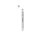
- FIG. 1A is a top view of the tablet terminal 10 to which the touch panel unit 100 according to the present embodiment is attached
- FIG. 1B is a side view
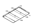
- FIG. 2 is a perspective view of touch panel unit 100 in the present embodiment
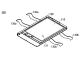
- FIG. 3 is a perspective view of the tablet terminal 10 and the touch panel unit 100 in a state before the touch panel unit 100 is attached to the tablet terminal 10
- FIG. 4 is a perspective view of a state in which the touch panel unit 100 is attached to the tablet terminal 10. It is.
- the touch panel unit 100 in this embodiment has a touch panel 110 and is attached to the tablet terminal 10 including the touch panel 20 shown in FIG. 1A.
- the touch panel 20 provided in the tablet terminal 10 is a capacitive touch panel that employs a capacitive contact position detection method.
- the touch panel unit 100 includes a touch panel 110, a bezel cover 120, and fixing tapes 130a and 130b, as shown in FIG.
- a recess 121 is formed in the bezel cover 120 so that the tablet terminal 10 can be inserted, and a touch panel 110 is installed in a central portion of the bezel cover 120.
- two fixing tapes 130 a and 130 b are connected to each side surface of the bezel cover 120.
- the fixing tapes 130a and 130b are, for example, hook-and-loop fasteners capable of attaching and detaching one and the other surface.
- the touch panel 110 is a resistive film type touch panel that employs a resistive film contact position detection method.
- the touch panel unit 100 in the present embodiment is attached to the tablet terminal 10 from the front side where the touch panel 20 of the tablet terminal 10 is installed, as shown in FIGS. 3 and 4. Specifically, by attaching the fixing tape 130a and the fixing tape 130b on the back side of the tablet terminal 10 in a state where the tablet terminal 10 is inserted into the concave portion 121 of the touch panel unit 100 in the present embodiment from the front side.
- the touch panel unit 100 is attached to the tablet terminal 10.
- the touch panel 20 may be a resistive touch panel
- the touch panel 110 of the touch panel unit 100 may be a capacitive touch panel. That is, in order to be able to use a plurality of types of touch panels with a single tablet terminal, the touch panel 20 mounted on the tablet terminal 10 and the touch panel 110 of the touch panel unit 100 have different detection methods. Good.
- FIG. 5 is an orthographic view of the touch panel unit 200 in the present embodiment
- FIG. 6 is a perspective view of the tablet terminal 10 and the touch panel unit 200 in a state before the touch panel unit 200 is attached to the tablet terminal 10.
- FIG. 7 is a cross-sectional view taken along a dashed line 5A-5B in FIG. 5 in a state where the touch panel unit 200 is attached to the tablet terminal 10.
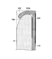
- 8A and 8B are partial enlarged views of FIG.
- the touch panel unit 200 in this embodiment includes a touch panel 110 and a bezel cover 220.
- the bezel cover 220 is formed with a recess so that the tablet terminal 10 can be inserted, and the touch panel 110 is installed at the center of the bezel cover 220.
- the mounting hole 11 is provided in one side surface 10 a of the side surfaces in the longitudinal direction of the tablet terminal 10, and the inside of the one side surface 220 a of the bezel cover 220 has the tablet terminal 10.
- Protrusions 221 that are inserted into the attachment holes 11 provided on the side surface 10a are provided.
- the other side surface 220b of the bezel cover 220 facing the side surface 220a on which the protruding portion 221 is formed is bent inward to form a lock portion 222.
- the touch panel unit 200 can be attached to the tablet terminal 10 by inserting 10b inside the lock portion 222 formed on the other side surface 220b of the bezel cover 220.
- the touch panel unit 200 is configured such that the operation pen 230 used for operating the touch panel 110 can be stored in the bezel cover 220. Good.
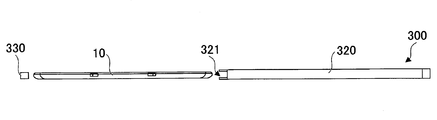
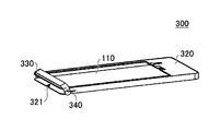
- FIGS. 10 is a perspective view of a state before the tablet terminal 10 is inserted into the touch panel unit 300 according to the present embodiment
- FIG. 11 is a perspective view of a state where the tablet terminal 10 is inserted into the touch panel unit 300. is there.
- 12 is a side view of the state before the tablet terminal 10 is inserted into the touch panel unit 300
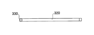
- FIG. 13 is a side view of the state where the tablet terminal 10 is inserted into the touch panel unit 300 and the lid 330 is closed. is there.
- the touch panel unit 300 in this embodiment includes a touch panel 110, a bezel cover 320, and a lid 330.
- the bezel cover 320 is formed in a box shape so that the tablet terminal 10 can be accommodated, and has an opening 321 into which the tablet terminal 10 can be inserted.
- the tablet terminal 10 is inserted into the bezel cover 320 through the opening 321 so that the side on which the touch panel 20 is provided faces the touch panel 110 of the touch panel unit 300, and the opening 321 is closed by the lid 330.
- the lid 330 may be formed of metal or the like, or may be formed of waterproof tape or rubber. When the lid 330 is formed of waterproof tape or rubber, the bezel cover 320 can be sealed, so that the touch panel unit 300 has a waterproof structure.
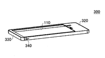
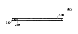
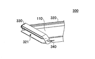
- the lid 330 may be connected to the bezel cover 320 by a spring 340 as shown in FIGS. 14 is a perspective view of a state in which the lid 330 is closed in the touch panel unit 300 in which the lid 330 is attached to the bezel cover 320 by a spring 340,
- FIG. 15 is a side view
- FIG. FIG. 15 is a partially enlarged view of FIG. 14.
- FIG. 17 is a perspective view showing a state in which the lid 330 is open
- FIG. 18 is a side view
- FIG. 19 is an enlarged perspective view of a main part.
- the tablet terminal 10 is inserted into the bezel cover 320 through the opening 321 with the lid 330 connected to the bezel cover 320 by the spring 340 open, and the lid 330 is closed, whereby the tablet terminal is placed inside the touch panel unit 300. 10 can be installed.
- a connector 350 that is connected to a connector (not shown) provided in the tablet terminal 10 can be It may be provided inside.
- 20 is a perspective view of the touch panel unit 300 in which a connector 350 is provided inside the bezel cover 320
- FIG. 21A is a top view
- FIG. 21B is a cross-sectional view taken along one-dot chain line 21A-21B in FIG. 21A. It is.
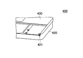
- FIGS. 22 is a perspective view of the touch panel unit 400 in the present embodiment
- FIG. 23 is a partially enlarged view of FIG. 22
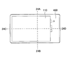
- FIG. 24 is a diagram illustrating the tablet terminal 10 installed in the touch panel unit 400 in the present embodiment.
- 25 is a cross-sectional view taken along one-dot chain line 24A-24B in FIG. 24,
- FIG. 26 is a partially enlarged view of FIG. 25, and
- FIG. 27 is a one-dot chain line 24C- It is sectional drawing in 24D.
- the touch panel unit 400 in this embodiment includes a touch panel 110, a housing 420, and a bezel cover 430.
- the touch panel 110 is installed on the bezel cover 430.
- the case 420 is formed in a concave shape so that the tablet terminal 10 can be accommodated, and groove portions 421 are formed on both side surfaces inside the case 420 so that the bezel cover 430 can slide and move.
- a fixing portion 422 having a shape corresponding to the outer shape of the tablet terminal 10 is formed inside the housing 420 formed in a concave shape. Since the position of the tablet terminal 10 placed inside the housing 420 formed in a concave shape is determined by the fixing portion 422, the tablet terminal 10 can be installed at a desired position. In this state, the tablet terminal 10 can be installed in the touch panel unit 400 in the present embodiment by inserting the bezel cover 430 into the groove portions 421 on both sides of the housing 420 and sliding the bezel cover 430 to close the bezel cover 430. .
- FIG. 28 is a perspective view of the touch panel unit 500 in the present embodiment
- FIG. 29 is a perspective view of a state in which the tablet terminal 10 is inserted into the touch panel unit 500 and the bezel cover 530 is partially opened.
- FIG. 30 is a top view of a state in which the tablet terminal 10 is installed on the touch panel unit 500.
- the touch panel unit 500 in the present embodiment includes a touch panel 110, a housing 520, and a bezel cover 530.
- the touch panel 110 is installed on the bezel cover 530.
- the housing 520 is formed in a concave shape so that the tablet terminal 10 can be accommodated, and the bezel cover 530 is connected to the corner portion of the housing 520 in a state of being rotatable around the shaft portion 521.
- a fixed portion 522 having a shape corresponding to the outer shape of the tablet terminal 10 is formed inside the housing 520 formed in a concave shape.
- the tablet terminal 10 can be installed at a desired position by the fixing portion 522 inside the housing 520 formed in a concave shape. With the tablet terminal 10 in the housing 520, the bezel cover 530 is rotated around the shaft 521 and closed as shown in FIG. The tablet terminal 10 can be installed.
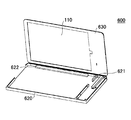
- FIG. 31 is a perspective view of the touch panel unit 600 in the present embodiment
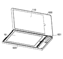
- FIG. 32 is a perspective view of a state in which the tablet terminal 10 is inserted into the touch panel unit 600 and the bezel cover 630 is opened.
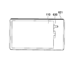
- FIG. 33 is a top view of a state in which the tablet terminal 10 is installed on the touch panel unit 600.
- the touch panel unit 600 in this embodiment includes a touch panel 110, a housing 620, and a bezel cover 630.
- the touch panel 110 is installed on the bezel cover 630.
- the housing 620 is formed in a concave shape so that the tablet terminal 10 can be accommodated, and the bezel cover 630 can be opened and closed around the shaft portion 621 along the side edge of the housing 620. It is connected to the.
- a fixing portion 622 having a shape corresponding to the outer shape of the tablet terminal 10 is formed inside the housing 620 formed in a concave shape.
- the tablet terminal 10 is placed in a desired position by the fixing portion 622 by being put inside the housing 620 formed in a concave shape. In this state, by closing the bezel cover 630 around the shaft portion 621, the tablet terminal 10 can be installed in the touch panel unit 600 in the present embodiment as shown in FIG.
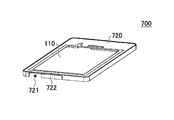
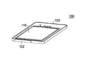
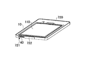
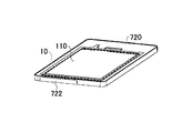
- FIGS. 34 and 35 are perspective views of the touch panel unit 700 in the present embodiment.
- FIG. 34 shows a state in which the slide cover 722 provided on the bezel cover 720 is open
- FIG. 35 shows the slide cover 722.
- 36 and 37 are perspective views of a state in which the tablet terminal 10 is put in the touch panel unit 700
- FIG. 36 shows a state in which a slide cover 722 provided on the bezel cover 720 is open
- FIG. The state where the slide cover 722 is closed is shown.
- the touch panel unit 700 in this embodiment includes a touch panel 110, a bezel cover 720, and a slide cover 722.
- the touch panel 110 is installed on the bezel cover 720, and the bezel cover 720 is formed so that the tablet terminal 10 can be accommodated.
- On the side surface of the bezel cover 720 an opening 721 is formed at a position corresponding to the position where the connection terminal 40 of the tablet terminal 10 is provided, and a slide cover 722 for opening and closing the opening 721 is provided.
- connection terminal 40 in the tablet terminal 10 can be exposed from the opening 721 by sliding the slide cover 722 to open. Thereby, even when the tablet terminal 10 is put in the touch panel unit 700, the connection terminal 40 in the tablet terminal 10 and a connector (not shown) outside the touch panel unit 700 can be connected.
- the touch panel to be used is manually switched in a state where the touch panel unit is attached to the tablet terminal and the connector of the touch panel unit (for example, the connector 350 in FIGS. 20 and 21B) and the connector of the tablet terminal are connected.
- the connector of the touch panel unit for example, the connector 350 in FIGS. 20 and 21B
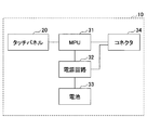
- the tablet terminal 10 includes an electrostatic membrane type touch panel 20, an MPU (Micro-processing unit) 31, a power supply circuit 32, a battery 33, and a connector 34.
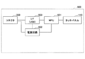
- the touch panel unit 800 includes a resistive film type touch panel 110, an MPU 821, a power supply circuit 822, an I / F 823, and a connector 350.
- the connector 34 of the tablet terminal 10 and the connector 350 of the touch panel unit 800 are connected. Power may be supplied to the touch panel unit 800 from the battery 33 of the tablet terminal 10 by connecting the connectors 34 and 350.
- a battery may be mounted on the touch panel unit 800 and power may be supplied from the touch panel unit 800 to the tablet terminal 10.
- step 102 an application activation process is performed in the tablet terminal 10. Specifically, the tablet terminal 10 is started up.
- step 104 an input device selection screen is displayed on the display of the tablet terminal 10 for selection of the touch panel.
- the capacitive touch panel 20 is used, the resistive touch panel 110 is used, or the capacitive touch panel 20 and the resistive touch panel 110 are used.
- a selection screen for selecting whether to use both is displayed.
- step 106 the operator touches the selection screen displayed on the tablet terminal 10, thereby causing the capacitive touch panel 20, the resistive touch panel 110, or the capacitive touch panel. 20 and the resistance film type touch panel 110 are used.
- the capacitive touch panel 20 is selected, the process proceeds to step 108. If the resistive touch panel 110 is selected, the process proceeds to step 110. If both the capacitive touch panel 20 and the resistive touch panel 110 are selected, the process proceeds to step 112.
- step 108 after the capacitive touch panel 20 is selected and the selection screen disappears, the on state of the capacitive touch panel 20 is continued. That is, the tablet terminal 10 can be operated as usual even after step 108.
- step 110 control for using the resistive touch panel 110 in the tablet terminal 10 is started. Specifically, in order to perform control to turn off the capacitive touch panel 20 and turn on the resistive touch panel 110, the process proceeds to step 114.
- step 112 the tablet terminal 10 performs control for using both the capacitive touch panel 20 and the resistive touch panel 110. Specifically, the process proceeds to step 114 in order to continue the ON state of the capacitive touch panel 20 and perform control to turn on the resistive touch panel 110.
- step 114 the display of the selection screen disappears in the tablet terminal 10.
- step 116 the resistive touch panel 110 is turned on.
- an instruction is issued from the tablet terminal 10 to the touch panel unit 800.
- step 132 the touch panel unit 800 performs a touch panel activation process, and turns on the resistive touch panel 110.
- step 134 it is determined whether or not there is a touch on the resistive touch panel 110. If there is contact with the resistive touch panel 110, the process proceeds to step 136. If contact with the resistive touch panel 110 is not detected, step 134 is repeated.
- the touch panel unit 800 detects the coordinates of the touched position on the resistive touch panel 110 in step 136 (S136). .
- step 138 position coordinate data detected by the resistive touch panel 110 is output from the touch panel unit 800 to the tablet terminal 10.
- touch panel unit 800 determines in step 140 (S140) whether to turn off the power. If it is determined that the power is to be turned off by the operation of the operator, the process is terminated.
- step 138 when the position coordinate data detected by the resistive touch panel 110 is output from the touch panel unit 800 to the tablet terminal 10, in step 118 (S118), the position coordinate data is output to the tablet terminal 10. Data is entered.
- step 120 processing by the application is performed based on the position coordinate data input to the tablet terminal 10.
- step 122 it is determined whether or not the application is to be ended. If it is determined that the application is to be ended, the process proceeds to step 124, and if it is determined that the application is not to be ended. , The process proceeds to step 118.
- step 124 the tablet terminal 10 performs control to turn off the resistive touch panel 110, and this instruction is transmitted to the touch panel unit 800. Thus, the power of the touch panel unit 800 is turned off.
- step S114 and the subsequent steps are executed, and as in the case of moving to step 108, the step is performed. From 112 onward, the on-state of the capacitive touch panel 20 is continued. When contact is detected by the capacitive touch panel 20, the tablet terminal 10 performs processing according to the detected content.
- the tablet terminal is attached to the touch panel unit, and the touch panel used is connected to the connector of the touch panel unit (for example, the connector 350 in FIGS. 20 and 21B) and the connector of the tablet terminal.
- the electrostatic film type touch panel 20 is automatically switched to the resistive film type touch panel 110 of the touch panel unit 800.
- the tablet terminal 10 and the touch panel unit 800 are the same as those in the eighth embodiment.
- step 202 an application activation process is performed in the tablet terminal 10. Specifically, the tablet terminal 10 is started up.
- step 216 control is performed to turn on the resistance film type touch panel 110.
- step 232 in response to an instruction from the tablet terminal 10, the touch panel unit 800 performs a touch panel activation process to turn on the resistive touch panel 110.
- the process of step 216 is performed when the tablet terminal 10 detects that the connector 350 of the touch panel unit 800 is connected to the connector 34 of the tablet terminal 10.
- step 234 it is determined whether or not there is a contact with the resistive touch panel 110. If there is contact with the resistive touch panel 110, the process proceeds to step 236. If there is no contact with the resistive touch panel 110, step 234 is repeated.
- step 234 if there is a contact with the resistive touch panel 110, the touch panel unit 800 detects the coordinates of the touched position on the resistive touch panel 110 in step 236 (S236).
- step 238 the detected coordinate data of the contact position of the resistive touch panel 110 is output from the touch panel unit 800 to the tablet terminal 10.
- touch panel unit 800 determines in step 240 (S240) whether or not to turn off the power. If it is determined that the power is to be turned off, the process ends, and if it is determined not to turn off the power. Then, the process proceeds to step 234.
- step 238 when the position coordinate data detected by the resistive touch panel 110 is output from the touch panel unit 800 to the tablet terminal 10, the position coordinate data is stored in the tablet terminal 10 in step 218 (S218). Entered.
- step 220 processing by the application is performed based on the input coordinate data.
- step 222 it is determined whether or not the application is to be ended. If it is determined that the application is to be ended, the process proceeds to step 224, and if it is determined that the application is not to be ended. The process proceeds to step 218.
- step 224 the tablet terminal 10 performs control to turn off the resistive touch panel 110. This instruction is transmitted to the touch panel unit 800, and the power of the touch panel unit 800 is turned off.
- the touch panel unit bezel cover, casing, and the like may be formed of a resin material, metal, rubber, or the like. Communication between the touch panel unit and the tablet terminal 10 may be performed wirelessly.
- the touch panel unit of the above embodiment can be applied to an information terminal other than a tablet terminal, such as a smartphone.
Landscapes
- Engineering & Computer Science (AREA)
- Theoretical Computer Science (AREA)
- General Engineering & Computer Science (AREA)
- Human Computer Interaction (AREA)
- Physics & Mathematics (AREA)
- General Physics & Mathematics (AREA)
- Computer Hardware Design (AREA)
- Position Input By Displaying (AREA)
Abstract
情報端末に取り付け可能なタッチパネルユニットは、ベゼルカバーと、前記ベゼルカバーに設けられた第1のタッチパネルとを備える。前記タッチパネルユニットは、前記情報端末の第2のタッチパネルの上に前記第1のタッチパネルが位置するように、前記情報端末に取り付け可能に構成されており、前記第1のタッチパネルと前記第2のタッチパネルとは、接触位置検出方式が異なる。
Description
本開示の一側面は、タッチパネルユニットに関する。
タッチパネルは、タブレット端末などの装置のディスプレイの前面に設置され、ディスプレイに表示されたユーザインタフェースを介して装置の操作や情報の入力を行うことを可能にする入力デバイスであり、様々な用途に用いられている。
このようなタッチパネルとしては、抵抗膜方式のタッチパネル及び静電容量方式のタッチパネルが広く知られている。抵抗膜方式のタッチパネルは、透明導電膜が形成された上部電極基板及び下部電極基板が対向するように設置されており、上部電極基板に力を加えることにより各々の透明導電膜同士が接触し、力の加えられた位置の検出を行うことができる。
抵抗膜方式のタッチパネルは、4線式、5線式に大別することができる。4線式は、上部電極基板又は下部電極基板のどちらか一方にX軸の電極が設けられており、他方にY軸の電極が設けられている(例えば、特許文献1)。また、5線式は、下部電極基板にX軸の電極及びY軸の電極が設けられており、上部電極基板は、電圧を検出するためのプローブとして機能する(例えば、特許文献2)。
また、静電容量方式のタッチパネルでは、タッチパネルに指等が接近することによりタッチパネルの透明電極等に流れる電流を検出することにより位置検出がなされる。
このように異なる特徴を有する抵抗膜方式のタッチパネルと静電容量方式のタッチパネルとを積層した構造のタッチパネルが開示されている(例えば、特許文献3、4)。
ところで、静電容量方式のタッチパネルは、静電容量結合により位置検出を行うため、ユーザがタッチパネルを押下することなく触れただけで、その位置を検出することができるが、絶縁体により接触された位置を検出することはできない。また、抵抗膜方式のタッチパネルでは、タッチパネルを押下する物体の材質に関わらず位置検出を行うことができるが、上部抵抗膜となる透明導電膜と下部抵抗膜となる透明導電膜とが接触した位置を検出するため、タッチパネルを所定の力で押下する必要がある。
市販されているタブレット端末には、主に静電容量方式のタッチパネルが用いられているため、絶縁体による接触位置を検出をすることができない。
また、特許文献3及び4に記載されている、静電容量方式のタッチパネルと抵抗膜方式のタッチパネルとを積層したタッチパネルは、特殊な構造であるため、現状において、市販されているタブレット端末に搭載することは容易ではない。
このため、市販されているタブレット端末に、静電容量方式と抵抗膜方式の双方のタッチパネルを備えさせることができる技術が求められていた。
本開示の一側面によれば、情報端末に取り付け可能なタッチパネルユニットが提供される。前記タッチパネルユニットは、ベゼルカバーと、前記ベゼルカバーに設けられた第1のタッチパネルとを備える。前記タッチパネルユニットは、前記情報端末の第2のタッチパネルの上に前記第1のタッチパネルが位置するように、前記情報端末に取り付け可能に構成されており、前記第1のタッチパネルと前記第2のタッチパネルとは、接触位置検出方式が異なる。
本開示の一側面によれば、市販されているタブレット端末に、静電容量方式と抵抗膜方式の双方のタッチパネルを備えさせることができるタッチパネルユニットが提供される。
本発明を実施するための形態について、以下に説明する。尚、同じ部材等については、同一の符号を付して説明を省略する。
〔第1の実施の形態〕
第1の実施の形態におけるタッチパネルユニットについて図1Aから図4に基づき説明する。図1Aは本実施の形態におけるタッチパネルユニット100が取り付けられるタブレット端末10の上面図であり、図1Bは側面図である。図2は、本実施の形態におけるタッチパネルユニット100の斜視図である。図3は、タッチパネルユニット100がタブレット端末10に取り付けられる前の状態のタブレット端末10とタッチパネルユニット100の斜視図であり、図4は、タッチパネルユニット100がタブレット端末10に取り付けられた状態の斜視図である。
第1の実施の形態におけるタッチパネルユニットについて図1Aから図4に基づき説明する。図1Aは本実施の形態におけるタッチパネルユニット100が取り付けられるタブレット端末10の上面図であり、図1Bは側面図である。図2は、本実施の形態におけるタッチパネルユニット100の斜視図である。図3は、タッチパネルユニット100がタブレット端末10に取り付けられる前の状態のタブレット端末10とタッチパネルユニット100の斜視図であり、図4は、タッチパネルユニット100がタブレット端末10に取り付けられた状態の斜視図である。
本実施の形態におけるタッチパネルユニット100は、タッチパネル110を有しており、図1Aに示されるタッチパネル20を備えるタブレット端末10に装着されるものである。尚、タブレット端末10に備えられたタッチパネル20は、静電容量接触位置検出方式を採用した静電容量方式タッチパネルである。
本実施の形態におけるタッチパネルユニット100は、図2に示されるように、タッチパネル110、ベゼルカバー120、固定用テープ130a、130bを有している。ベゼルカバー120には、タブレット端末10が入れられるように凹部121が形成されており、ベゼルカバー120の中央部分にはタッチパネル110が設置されている。図4に示されるように、ベゼルカバー120の各側面には、固定用テープ130a、130bが各々2本ずつ接続されている。固定用テープ130a、130bは、例えば、一方と他方とを面的に着脱することのできる面ファスナーである。尚、タッチパネル110は、抵抗膜接触位置検出方式を採用した抵抗膜方式タッチパネルである。
本実施の形態におけるタッチパネルユニット100は、図3及び図4に示されるように、タブレット端末10のタッチパネル20が設置されている表側よりタブレット端末10に取り付けられる。具体的には、本実施の形態におけるタッチパネルユニット100の凹部121にタブレット端末10を表側より入れた状態で、タブレット端末10の裏側において、固定用テープ130aと固定用テープ130bとを貼り合わせることにより、タブレット端末10にタッチパネルユニット100が取り付けられる。
尚、ここではタブレット端末10に搭載されているタッチパネル20が静電容量方式のタッチパネルであり、タッチパネルユニット100におけるタッチパネル110が抵抗膜方式のタッチパネルである場合について説明するが、タブレット端末10に搭載されるタッチパネル20が抵抗膜方式のタッチパネルであって、タッチパネルユニット100のタッチパネル110が静電容量方式のタッチパネルであってもよい。即ち、複数種のタッチパネルを一台のタブレット端末で使用できるようにするためには、タブレット端末10に搭載されているタッチパネル20とタッチパネルユニット100のタッチパネル110とは、その検出方式が異なっていればよい。
〔第2の実施の形態〕
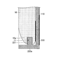
次に、第2の実施の形態におけるタッチパネルユニットについて、図5から図8Bに基づき説明する。図5は、本実施の形態におけるタッチパネルユニット200の正投影図であり、図6は、タッチパネルユニット200がタブレット端末10に取り付けられる前の状態のタブレット端末10とタッチパネルユニット200の斜視図である。図7は、タブレット端末10にタッチパネルユニット200が取り付けられている状態において、図5における一点鎖線5A-5Bに相当する部分で切断した断面図である。図8A、8Bは、図7の部分拡大図である。
次に、第2の実施の形態におけるタッチパネルユニットについて、図5から図8Bに基づき説明する。図5は、本実施の形態におけるタッチパネルユニット200の正投影図であり、図6は、タッチパネルユニット200がタブレット端末10に取り付けられる前の状態のタブレット端末10とタッチパネルユニット200の斜視図である。図7は、タブレット端末10にタッチパネルユニット200が取り付けられている状態において、図5における一点鎖線5A-5Bに相当する部分で切断した断面図である。図8A、8Bは、図7の部分拡大図である。
本実施の形態におけるタッチパネルユニット200は、タッチパネル110、ベゼルカバー220を有している。ベゼルカバー220は、タブレット端末10が入れられるように凹部が形成されており、ベゼルカバー220の中央部分にタッチパネル110が設置されている。本実施の形態においては、タブレット端末10の長手方向の側面のうち、一方の側面10aには取り付け穴11が設けられており、ベゼルカバー220の一方の側面220aの内側には、タブレット端末10の側面10aに設けられた取り付け穴11に入れられる突起部221が設けられている。ベゼルカバー220の突起部221が形成されている側面220aに対向する他方の側面220bは、内側に曲げられておりロック部222が形成されている。
本実施の形態においては、ベゼルカバー220の一方の側面220aの内側の突起部221をタブレット端末10の一方の側面10aに設けられた取り付け穴11に入れた状態で、タブレット端末10の他方の側面10bをベゼルカバー220の他方の側面220bに形成されたロック部222の内側に入れることにより、タブレット端末10にタッチパネルユニット200を取り付けることができる。
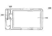
また、本実施の形態の変形例によれば、タッチパネルユニット200は、図9に示されるように、タッチパネル110を操作するために用いる操作ペン230が、ベゼルカバー220に収納できるものであってもよい。
〔第3の実施の形態〕
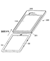
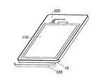
次に、第3の実施の形態におけるタッチパネルユニットについて、図10から図12に基づき説明する。尚、図10は、本実施の形態におけるタッチパネルユニット300にタブレット端末10が入れられる前の状態の斜視図であり、図11は、タッチパネルユニット300にタブレット端末10が入れられた状態の斜視図である。図12は、タッチパネルユニット300にタブレット端末10が入れられる前の状態の側面図であり、図13は、タッチパネルユニット300にタブレット端末10が入れられ、蓋330が閉じられている状態の側面図である。
次に、第3の実施の形態におけるタッチパネルユニットについて、図10から図12に基づき説明する。尚、図10は、本実施の形態におけるタッチパネルユニット300にタブレット端末10が入れられる前の状態の斜視図であり、図11は、タッチパネルユニット300にタブレット端末10が入れられた状態の斜視図である。図12は、タッチパネルユニット300にタブレット端末10が入れられる前の状態の側面図であり、図13は、タッチパネルユニット300にタブレット端末10が入れられ、蓋330が閉じられている状態の側面図である。
本実施の形態におけるタッチパネルユニット300は、タッチパネル110、ベゼルカバー320、蓋330を有している。ベゼルカバー320は、タブレット端末10を収納できるように箱型に形成されており、タブレット端末10が入れられる開口部321を有している。タブレット端末10は、タッチパネル20が設けられている側が、タッチパネルユニット300のタッチパネル110と対向するように、開口部321よりベゼルカバー320内に入れられ、開口部321が蓋330により閉じられる。蓋330は、金属等により形成したものであってもよく、防水テープやゴムにより形成したものであってもよい。蓋330を防水テープやゴムにより形成した場合には、ベゼルカバー320を密封することができるため、タッチパネルユニット300は防水構造となる。
また、本実施の形態の変形例によるタッチパネルユニット300においては、図14から図19に示されるように、蓋330はベゼルカバー320にバネ340により接続されていてもよい。尚、図14は、蓋330がバネ340によりベゼルカバー320に取り付けられているタッチパネルユニット300において、蓋330が閉じられている状態の斜視図であり、図15は側面図であり、図16は、図14の部分拡大図である。また、図17は、蓋330が開いている状態の斜視図であり、図18は側面図であり、図19は、要部を拡大した斜視図である。
タブレット端末10を、ベゼルカバー320にバネ340により接続されている蓋330を開いた状態で、開口部321よりベゼルカバー320内に入れ、蓋330を閉じることにより、タッチパネルユニット300の内部にタブレット端末10を設置することができる。
また、本実施の形態の変形例によれば、図20、図21A、及び図21Bに示すように、タブレット端末10に設けられている不図示のコネクタと接続されるコネクタ350がベゼルカバー320の内側に設けられていてもよい。図20は、タッチパネルユニット300において、ベゼルカバー320の内側にコネクタ350が設けられているものの斜視図であり、図21Aは上面図であり、図21Bは図21Aの一点鎖線21A-21Bにおける断面図である。
〔第4の実施の形態〕
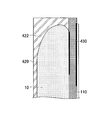
次に、第4の実施の形態におけるタッチパネルユニットについて、図22から図27に基づき説明する。尚、図22は、本実施の形態におけるタッチパネルユニット400の斜視図であり、図23は図22の部分拡大図であり、図24は、本実施の形態におけるタッチパネルユニット400にタブレット端末10が設置されている状態の上面図であり、図25は図24における一点鎖線24A-24Bにおける断面図であり、図26は、図25の部分拡大図であり、図27は図24における一点鎖線24C-24Dにおける断面図である。
次に、第4の実施の形態におけるタッチパネルユニットについて、図22から図27に基づき説明する。尚、図22は、本実施の形態におけるタッチパネルユニット400の斜視図であり、図23は図22の部分拡大図であり、図24は、本実施の形態におけるタッチパネルユニット400にタブレット端末10が設置されている状態の上面図であり、図25は図24における一点鎖線24A-24Bにおける断面図であり、図26は、図25の部分拡大図であり、図27は図24における一点鎖線24C-24Dにおける断面図である。
本実施の形態におけるタッチパネルユニット400は、タッチパネル110、筐体420、ベゼルカバー430を有している。タッチパネル110は、ベゼルカバー430に設置されている。筐体420は、タブレット端末10を収納できるように凹状に形成されており、筐体420の内側の両側面には、ベゼルカバー430がスライドして移動できるように溝部421が形成されている。凹状に形成されている筐体420の内側には、タブレット端末10の外形に対応した形状の固定部422が形成されている。凹状に形成されている筐体420の内部に入れられるタブレット端末10は、固定部422によりその位置が定まるため、タブレット端末10を所望の位置に設置できる。この状態で、筐体420の両側の溝部421にベゼルカバー430を入れてスライドさせてベゼルカバー430を閉じることにより、本実施の形態におけるタッチパネルユニット400内に、タブレット端末10を設置することができる。
〔第5の実施の形態〕
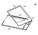
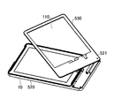
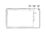
次に、第5の実施の形態におけるタッチパネルユニットについて、図28から図30に基づき説明する。尚、図28は、本実施の形態におけるタッチパネルユニット500の斜視図であり、図29は、タッチパネルユニット500にタブレット端末10が入れられてベゼルカバー530が一部開いている状態の斜視図である。図30は、タッチパネルユニット500にタブレット端末10が設置されている状態の上面図である。
次に、第5の実施の形態におけるタッチパネルユニットについて、図28から図30に基づき説明する。尚、図28は、本実施の形態におけるタッチパネルユニット500の斜視図であり、図29は、タッチパネルユニット500にタブレット端末10が入れられてベゼルカバー530が一部開いている状態の斜視図である。図30は、タッチパネルユニット500にタブレット端末10が設置されている状態の上面図である。
本実施の形態におけるタッチパネルユニット500は、タッチパネル110、筐体520、ベゼルカバー530を有している。タッチパネル110は、ベゼルカバー530に設置されている。筐体520は、タブレット端末10を収納できるように凹状に形成されており、ベゼルカバー530は、筐体520のコーナー部に、軸部521を中心に回転可能な状態で接続されている。
凹状に形成されている筐体520の内側には、タブレット端末10の外形に対応した形状の固定部522が形成されている。タブレット端末10は、凹状に形成されている筐体520の内部で固定部522により所望の位置に設置することができる。タブレット端末10を筐体520内に入れた状態で、軸部521を中心にベゼルカバー530を回転させて、図30に示すように、閉じることにより、本実施の形態におけるタッチパネルユニット500内に、タブレット端末10を設置することができる。
〔第6の実施の形態〕
次に、第6の実施の形態におけるタッチパネルユニットについて、図31から図33に基づき説明する。尚、図31は、本実施の形態におけるタッチパネルユニット600の斜視図であり、図32は、タッチパネルユニット600にタブレット端末10が入れられてベゼルカバー630が開いている状態の斜視図である。図33は、タッチパネルユニット600にタブレット端末10が設置されている状態の上面図である。
次に、第6の実施の形態におけるタッチパネルユニットについて、図31から図33に基づき説明する。尚、図31は、本実施の形態におけるタッチパネルユニット600の斜視図であり、図32は、タッチパネルユニット600にタブレット端末10が入れられてベゼルカバー630が開いている状態の斜視図である。図33は、タッチパネルユニット600にタブレット端末10が設置されている状態の上面図である。
本実施の形態におけるタッチパネルユニット600は、タッチパネル110、筐体620、ベゼルカバー630を有している。タッチパネル110は、ベゼルカバー630に設置されている。筐体620は、タブレット端末10を収納できるように凹状に形成されており、ベゼルカバー630は、筐体620の側面の縁に沿った軸部621を中心に開閉可能な状態で、筐体620に接続されている。
凹状に形成されている筐体620の内側には、タブレット端末10の外形に対応した形状の固定部622が形成されている。タブレット端末10は、凹状に形成されている筐体620の内部に入れることにより、固定部622により所望の位置に設置される。この状態で、軸部621を中心にベゼルカバー630を閉じることにより、図33に示すように、本実施の形態におけるタッチパネルユニット600内に、タブレット端末10を設置することができる。
〔第7の実施の形態〕
次に、第7の実施の形態におけるタッチパネルユニットについて、図34から図37に基づき説明する。尚、図34及び図35は、本実施の形態におけるタッチパネルユニット700の斜視図であり、図34はベゼルカバー720に設けられたスライドカバー722が開いている状態を示し、図35はスライドカバー722が閉じている状態を示す。図36及び図37は、タッチパネルユニット700にタブレット端末10が入れられている状態の斜視図であり、図36はベゼルカバー720に設けられたスライドカバー722が開いている状態を示し、図37はスライドカバー722が閉じている状態を示す。
次に、第7の実施の形態におけるタッチパネルユニットについて、図34から図37に基づき説明する。尚、図34及び図35は、本実施の形態におけるタッチパネルユニット700の斜視図であり、図34はベゼルカバー720に設けられたスライドカバー722が開いている状態を示し、図35はスライドカバー722が閉じている状態を示す。図36及び図37は、タッチパネルユニット700にタブレット端末10が入れられている状態の斜視図であり、図36はベゼルカバー720に設けられたスライドカバー722が開いている状態を示し、図37はスライドカバー722が閉じている状態を示す。
本実施の形態におけるタッチパネルユニット700は、タッチパネル110、ベゼルカバー720、スライドカバー722を有している。タッチパネル110は、ベゼルカバー720に設置されており、ベゼルカバー720は、タブレット端末10を収納できるように形成されている。ベゼルカバー720の側面には、タブレット端末10の接続端子40が設けられている位置に対応する位置に開口721が形成されており、開口721を開閉するためのスライドカバー722が設けられている。
図36に示すように、スライドカバー722をスライドさせて開くことにより、タブレット端末10における接続端子40を開口721より露出させることができる。これにより、タッチパネルユニット700内にタブレット端末10が入れられている状態においても、タブレット端末10における接続端子40とタッチパネルユニット700の外の不図示のコネクタとを接続することができる。
〔第8の実施の形態〕
次に、第8の実施の形態について説明する。本実施の形態では、タブレット端末にタッチパネルユニットを取り付けてタッチパネルユニットのコネクタ(例えば、図20及び図21Bにおけるコネクタ350)とタブレット端末のコネクタとを接続した状態において、用いるタッチパネルを手動で切り替える。
次に、第8の実施の形態について説明する。本実施の形態では、タブレット端末にタッチパネルユニットを取り付けてタッチパネルユニットのコネクタ(例えば、図20及び図21Bにおけるコネクタ350)とタブレット端末のコネクタとを接続した状態において、用いるタッチパネルを手動で切り替える。
図38Aに示されるように、タブレット端末10は、静電膜方式のタッチパネル20、MPU(Micro-processing unit)31、電源回路32、電池33、コネクタ34を有している。図38Bに示されるように、タッチパネルユニット800は、抵抗膜方式のタッチパネル110、MPU821、電源回路822、I/F823、コネクタ350を有している。本実施の形態においては、タブレット端末10にタッチパネルユニット800を取り付けることにより、タブレット端末10のコネクタ34とタッチパネルユニット800のコネクタ350とが接続される。コネクタ34、350の接続により、タブレット端末10の電池33よりタッチパネルユニット800に電力を供給するものであってもよい。尚、タッチパネルユニット800に電池を搭載し、タッチパネルユニット800よりタブレット端末10に電力を供給するものであってもよい。
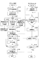
図39に基づき、用いるタッチパネルを手動で切り替える方法について説明する。
最初に、ステップ102(S102)では、タブレット端末10においてアプリケーション起動処理を行う。具体的には、タブレット端末10を立ち上げる。
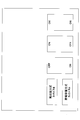
次に、ステップ104(S104)では、タッチパネルの選択のために、タブレット端末10のディスプレイに入力デバイスの選択画面を表示する。具体的には、図40に示されるように、静電容量方式のタッチパネル20を使用するか、抵抗膜方式のタッチパネル110を使用するか、静電容量方式のタッチパネル20と抵抗膜方式のタッチパネル110の双方を使用するか、を選択する選択画面が表示される。
次に、ステップ106(S106)では、操作者は、タブレット端末10に表示された選択画面に触れることにより、静電容量方式のタッチパネル20、抵抗膜方式のタッチパネル110、あるいは静電容量方式のタッチパネル20と抵抗膜方式のタッチパネル110の双方を使用するかを選択する。静電容量方式のタッチパネル20が選択された場合には、ステップ108に移行する。抵抗膜方式のタッチパネル110が選択された場合には、ステップ110に移行する。静電容量方式のタッチパネル20と抵抗膜方式のタッチパネル110の双方が選択された場合には、ステップ112に移行する。
ステップ108(S108)においては、静電容量方式のタッチパネル20が選択されて選択画面の表示が消えた後、静電容量方式のタッチパネル20のオン状態が継続される。つまり、ステップ108の後も通常通りタブレット端末10を操作することができる。
ステップ110(S110)においては、タブレット端末10において、抵抗膜方式のタッチパネル110を使用するための制御が開始される。具体的には、静電容量方式のタッチパネル20をオフとし、抵抗膜方式のタッチパネル110をオンとする制御を行うために、ステップ114に移行する。
ステップ112(S112)においては、タブレット端末10において、静電容量方式のタッチパネル20と、抵抗膜方式のタッチパネル110との双方を使用するための制御を行う。具体的には、静電容量方式のタッチパネル20のオン状態を継続し、抵抗膜方式のタッチパネル110をオンとする制御を行うために、ステップ114に移行する。
ステップ114(S114)では、タブレット端末10において、選択画面の表示が消える。
次に、ステップ116(S116)では、抵抗膜方式のタッチパネル110の電源をオンにする。この際は、タブレット端末10からタッチパネルユニット800に対して指示が発行される。これにより、ステップ132(S132)において、タッチパネルユニット800はタッチパネルの起動処理を行い、抵抗膜方式のタッチパネル110をオン状態にする。
次に、ステップ134(S134)に示されるように、抵抗膜方式のタッチパネル110において接触があったか否かが判断される。抵抗膜方式のタッチパネル110への接触があった場合には、ステップ136に移行する。抵抗膜方式のタッチパネル110への接触が検出されなかった場合には、ステップ134が繰り返される。
ステップ134において、抵抗膜方式のタッチパネル110への接触が検出された場合には、ステップ136(S136)において、タッチパネルユニット800は、抵抗膜方式のタッチパネル110上の接触された位置の座標を検出する。
次に、ステップ138(S138)では、抵抗膜方式のタッチパネル110により検出された位置座標のデータが、タッチパネルユニット800からタブレット端末10に向けて出力される。この後、タッチパネルユニット800は、ステップ140(S140)において、電源をオフするか否かを判断する。操作者の操作により電源をオフすると判断された場合には処理を終了し、電源をオフしないと判断された場合には、ステップ134に移行する。
ステップ138において、抵抗膜方式のタッチパネル110により検出された位置座標のデータが、タッチパネルユニット800からタブレット端末10に向けて出力されると、ステップ118(S118)において、タブレット端末10に、位置座標のデータが入力される。
次に、ステップ120(S120)において、タブレット端末10に入力された位置座標のデータに基づきアプリケーションによる処理が行われる。
次に、ステップ122(S122)において、アプリケーションを終了するか否かの判断がなされ、アプリケーションを終了すると判断された場合には、ステップ124に移行し、アプリケーションを終了しないと判断された場合には、ステップ118に移行する。
ステップ122において、アプリケーションを終了すると判断された場合には、ステップ124(S124)において、タブレット端末10は、抵抗膜方式のタッチパネル110をオフにする制御を行い、この指示がタッチパネルユニット800に送信されて、タッチパネルユニット800の電源がオフになる。
尚、ステップ106で抵抗膜方式のタッチパネル110と静電容量方式のタッチパネル20との双方を用いることが選択されたときには、ステップS114以降が実行されるとともに、ステップ108に移行した場合と同様、ステップ112以降も静電容量方式のタッチパネル20のオン状態が継続される。静電容量方式のタッチパネル20にて接触が検出された場合、タブレット端末10はその検出内容に応じた処理を行う。
〔第9の実施の形態〕
次に、第9の実施の形態について説明する。本実施の形態では、タッチパネルユニットにタブレット端末を取り付け、タッチパネルユニットのコネクタ(例えば、図20及び図21Bにおけるコネクタ350)とタブレット端末のコネクタとを接続することにより、用いられるタッチパネルを、タブレット端末10の静電膜方式のタッチパネル20から、タッチパネルユニット800の抵抗膜方式のタッチパネル110に自動的に切り替える。尚、タブレット端末10及びタッチパネルユニット800は、第8の実施の形態と同様のものである。
次に、第9の実施の形態について説明する。本実施の形態では、タッチパネルユニットにタブレット端末を取り付け、タッチパネルユニットのコネクタ(例えば、図20及び図21Bにおけるコネクタ350)とタブレット端末のコネクタとを接続することにより、用いられるタッチパネルを、タブレット端末10の静電膜方式のタッチパネル20から、タッチパネルユニット800の抵抗膜方式のタッチパネル110に自動的に切り替える。尚、タブレット端末10及びタッチパネルユニット800は、第8の実施の形態と同様のものである。
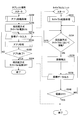
図41に基づき、用いるタッチパネルを切り替える方法について説明する。
最初に、ステップ202(S202)では、タブレット端末10においてアプリケーション起動処理を行う。具体的には、タブレット端末10を立ち上げる。
続いて、タッチパネルユニット800をタブレット端末10に取り付けることにより、ステップ216(S216)において、抵抗膜方式のタッチパネル110の電源をオンにする制御がなされる。そして、ステップ232(S232)において、タブレット端末10からの指示に応じてタッチパネルユニット800にがタッチパネルの起動処理を行い、抵抗膜方式のタッチパネル110をオン状態にする。ステップ216の処理は、タッチパネルユニット800のコネクタ350がタブレット端末10のコネクタ34に接続されたことをタブレット端末10が検出した際に行われる。
次に、ステップ234(S234)において、抵抗膜方式のタッチパネル110への接触があったか否かが判断される。抵抗膜方式のタッチパネル110への接触があった場合には、ステップ236に移行する。抵抗膜方式のタッチパネル110への接触がなかった場合には、ステップ234が繰り返される。
ステップ234において、抵抗膜方式のタッチパネル110への接触があった場合には、ステップ236(S236)において、タッチパネルユニット800は、抵抗膜方式のタッチパネル110上の接触された位置の座標を検出する。
次に、ステップ238(S238)において、検出された抵抗膜方式のタッチパネル110の接触位置の座標データが、タッチパネルユニット800からタブレット端末10に向けて出力される。この後、タッチパネルユニット800は、ステップ240(S240)において、電源をオフするか否かを判断し、電源をオフすると判断された場合には処理を終了し、電源をオフしないと判断された場合には、ステップ234に移行する。
ステップ238において、抵抗膜方式のタッチパネル110により検出された位置座標データがタッチパネルユニット800からタブレット端末10に向けて出力されると、ステップ218(S218)において、タブレット端末10に、位置座標のデータが入力される。
次に、ステップ220(S220)において、入力された座標データに基づきアプリケーションによる処理が行われる。
次に、ステップ222(S222)において、アプリケーションを終了するか否かの判断がなされ、アプリケーションを終了すると判断された場合には、ステップ224に移行し、アプリケーションを終了しないと判断された場合には、ステップ218に移行する。
ステップ222において、アプリケーションを終了すると判断された場合には、ステップ224(S224)において、タブレット端末10は、抵抗膜方式のタッチパネル110をオフにする制御を行う。この指示がタッチパネルユニット800に送信されて、タッチパネルユニット800の電源がオフになる。
タッチパネルユニットのベゼルカバー、筐体等は、樹脂材料、金属、ゴム等により形成されていてもよい。また、タッチパネルユニットとタブレット端末10との通信は、無線によるものであってもよい。
以上、本発明の実施形態について説明したが、本発明は上記の実施形態に限定されるものではなく、本発明の範囲において種々の変形・変更が可能である。
例えば、上記の実施形態のタッチパネルユニットは、タブレット端末以外の情報端末、例えばスマートフォンなどにも適用することができる。
本願は2014年12月26日に出願した日本国特許出願第2014-265724号に基づきその優先権を主張するものであり、同日本国出願の全内容を参照することにより本願に援用する。
10 タブレット端末
20 タッチパネル
100 タッチパネルユニット
110 タッチパネル
120 ベゼルカバー
130a 固定用テープ
130b 固定用テープ
20 タッチパネル
100 タッチパネルユニット
110 タッチパネル
120 ベゼルカバー
130a 固定用テープ
130b 固定用テープ
Claims (14)
- 情報端末に取り付け可能なタッチパネルユニットであって、
ベゼルカバーと、
前記ベゼルカバーに設けられた第1のタッチパネルと、
を有し、
前記タッチパネルユニットは、前記情報端末の第2のタッチパネルの上に前記第1のタッチパネルが位置するように、前記情報端末に取り付け可能に構成されており、
前記第1のタッチパネルと前記第2のタッチパネルとは、接触位置検出方式が異なることを特徴とするタッチパネルユニット。 - 前記第1のタッチパネル及び前記第2のタッチパネルのうちのいずれか一方は、抵抗膜方式のタッチパネルであり、他方が静電容量方式のタッチパネルであることを特徴とする請求項1に記載のタッチパネルユニット。
- 前記ベゼルカバーには、第1のファスナーと第2のファスナーが設けられており、
前記情報端末の前記第2のタッチパネルが設けられている面とは反対側の面において、前記第1のファスナーの一端と前記第2のファスナーの一端とを貼り合わせることにより、前記情報端末に前記タッチパネルユニットが固定されることを特徴とする請求項1に記載のタッチパネルユニット。 - 前記ベゼルカバーは、前記情報端末の前記第2のタッチパネルが設けられている面を覆う形状を有しており、
前記ベゼルカバーの一方の側面の内側には、前記情報端末の一方の側面に形成される取付穴に差し込み可能な突起部が設けられており、
前記ベゼルカバーの前記一方の側面に対向する他方の側面には、前記情報端末の他方の側面を保持するロック部が形成されていることを特徴とする請求項1に記載のタッチパネルユニット。 - 前記ベゼルカバーは箱型の形状を有しており、
前記ベゼルカバーには、前記情報端末を前記ベゼルカバー内に入れるための開口部が形成されており、
前記タッチパネルユニットは、前記開口部を閉じる蓋をさらに備えることを特徴とする請求項1に記載のタッチパネルユニット。 - 前記情報端末を収納するための、凹状に形成された筐体をさらに備え、
前記筐体の互いに対向する内側面には、前記ベゼルカバーがスライド可能に取り付けられる溝部が形成されており、
前記筐体と前記ベゼルカバーとにより囲まれた領域に、前記情報端末が設置されることを特徴とする請求項1に記載のタッチパネルユニット。 - 前記情報端末を収納するための、凹状に形成された筐体と、
軸部、とをさらに備え、
前記ベゼルカバーは、前記軸部により、前記筐体のコーナー部に回転可能に取り付けられていることを特徴とする請求項1に記載のタッチパネルユニット。 - 前記情報端末を収納するための、凹状に形成された筐体と、
前記筐体の側面の縁に沿って配置された軸部、とをさらに備え、
前記ベゼルカバーは、前記軸部を中心に開閉可能に、前記筐体に接続されていることを特徴とする請求項1に記載のタッチパネルユニット。 - 前記ベゼルカバーには、前記第1のタッチパネルを操作する操作ペンを収納する収納部が設けられていることを特徴とする請求項1に記載のタッチパネルユニット。
- 前記情報端末より前記タッチパネルユニットに電力が供給されることを特徴とする請求項1に記載のタッチパネルユニット。
- 前記ベゼルカバーの、前記情報端末のコネクタに対応する位置には、開口が設けられており、
前記ベゼルカバーは、前記開口を開閉するスライドカバーを備えていることを特徴とする請求項1に記載のタッチパネルユニット。 - 前記ベゼルカバーの内側には、前記情報端末のコネクタと接続されるコネクタが設けられていることを特徴とする請求項1に記載のタッチパネルユニット。
- 前記情報端末のコネクタと、前記ベゼルカバーのコネクタとが接続されると、前記タッチパネルユニットの前記第1のタッチパネルが使用可能な状態となるよう構成されていることを特徴とする請求項12に記載のタッチパネルユニット。
- 前記タッチパネルユニットが前記情報端末に取り付けられた後、前記タッチパネルユニットの前記第1のタッチパネルと前記情報端末の前記第2のタッチパネルのいずれを使用するかを選択可能とする選択手段をさらに備えることを特徴とする請求項1に記載のタッチパネルユニット。
Priority Applications (2)
| Application Number | Priority Date | Filing Date | Title |
|---|---|---|---|
| US15/537,934 US20170344070A1 (en) | 2014-12-26 | 2015-12-02 | Touch panel unit |
| CN201580070132.4A CN107148606A (zh) | 2014-12-26 | 2015-12-02 | 触控面板单元 |
Applications Claiming Priority (2)
| Application Number | Priority Date | Filing Date | Title |
|---|---|---|---|
| JP2014-265724 | 2014-12-26 | ||
| JP2014265724A JP6411210B2 (ja) | 2014-12-26 | 2014-12-26 | タッチパネルユニット |
Publications (1)
| Publication Number | Publication Date |
|---|---|
| WO2016104084A1 true WO2016104084A1 (ja) | 2016-06-30 |
Family
ID=56150116
Family Applications (1)
| Application Number | Title | Priority Date | Filing Date |
|---|---|---|---|
| PCT/JP2015/083881 Ceased WO2016104084A1 (ja) | 2014-12-26 | 2015-12-02 | タッチパネルユニット |
Country Status (4)
| Country | Link |
|---|---|
| US (1) | US20170344070A1 (ja) |
| JP (1) | JP6411210B2 (ja) |
| CN (1) | CN107148606A (ja) |
| WO (1) | WO2016104084A1 (ja) |
Families Citing this family (2)
| Publication number | Priority date | Publication date | Assignee | Title |
|---|---|---|---|---|
| JP7071337B2 (ja) | 2017-03-30 | 2022-05-18 | 株式会社島津製作所 | タッチパネル装置を備えた分析装置、その表示制御方法、及びプログラム |
| JP7800122B2 (ja) * | 2021-12-23 | 2026-01-16 | 株式会社リコー | 表示装置 |
Citations (6)
| Publication number | Priority date | Publication date | Assignee | Title |
|---|---|---|---|---|
| JPH04160427A (ja) * | 1990-10-23 | 1992-06-03 | Canon Inc | タッチパネル |
| JP2005056088A (ja) * | 2003-08-01 | 2005-03-03 | Ricoh Co Ltd | タッチパネル付きディスプレイ装置、タッチパネル付きディスプレイ装置の制御方法およびその方法をコンピュータに実行させるためのプログラム |
| JP2006309466A (ja) * | 2005-04-27 | 2006-11-09 | Pioneer Electronic Corp | タッチパネルのキャリブレーション制御方法、制御プログラム及び制御装置 |
| JP2010073071A (ja) * | 2008-09-19 | 2010-04-02 | Sony Computer Entertainment Inc | 入力装置及び入力操作補助パネル |
| JP2012043369A (ja) * | 2010-08-23 | 2012-03-01 | Toshiba Tec Corp | 表示装置用カバーおよびカバー付き表示装置 |
| JP2013093002A (ja) * | 2011-10-24 | 2013-05-16 | Patent Connections Co Ltd | カバーケースおよびカバーケースセット |
Family Cites Families (24)
| Publication number | Priority date | Publication date | Assignee | Title |
|---|---|---|---|---|
| US20030092468A1 (en) * | 2001-11-15 | 2003-05-15 | North Vaughn W. | Combination thinline phone and PDA |
| US7927796B2 (en) * | 2003-09-18 | 2011-04-19 | Bioarray Solutions, Ltd. | Number coding for identification of subtypes of coded types of solid phase carriers |
| US20060214871A1 (en) * | 2005-03-23 | 2006-09-28 | Ryuichi Iwamura | Additional thin display device for supplementing a primary display |
| CN101169694A (zh) * | 2006-10-26 | 2008-04-30 | 中强光电股份有限公司 | 面板固定装置 |
| WO2008115931A1 (en) * | 2007-03-19 | 2008-09-25 | James Burns | Attachable device accessory case cover with interchangeable components |
| US20080231605A1 (en) * | 2007-03-21 | 2008-09-25 | Kai-Ti Yang | Compound touch panel |
| TW200915820A (en) * | 2007-09-19 | 2009-04-01 | Giga Byte Tech Co Ltd | Touch panel structure having dual touch-modes, and signal processing method and device |
| CN101727223A (zh) * | 2008-10-14 | 2010-06-09 | 介面光电股份有限公司 | 双面复合式触控面板结构 |
| US7876288B1 (en) * | 2010-08-11 | 2011-01-25 | Chumby Industries, Inc. | Touchscreen with a light modulator |
| JP2012141690A (ja) * | 2010-12-28 | 2012-07-26 | Alps Electric Co Ltd | 入力装置 |
| CN102645954A (zh) * | 2011-02-16 | 2012-08-22 | 索尼爱立信移动通讯有限公司 | 便携式终端 |
| US8994686B2 (en) * | 2011-10-17 | 2015-03-31 | Topaz Systems, Inc. | Digitizer |
| US8743066B2 (en) * | 2011-12-09 | 2014-06-03 | Blackberry Limited | Electronic device with capacitive touch-sensitive display |
| JP2013232033A (ja) * | 2012-04-27 | 2013-11-14 | Nec Casio Mobile Communications Ltd | 端末装置、及び端末装置の制御方法 |
| CN104246665B (zh) * | 2012-04-27 | 2016-12-14 | 株式会社村田制作所 | 操作输入装置以及信息显示装置 |
| WO2013181644A1 (en) * | 2012-06-01 | 2013-12-05 | Treefrog Developments, Inc. | Housing for an electronic device with camera, microphone and flash isolation |
| US8928623B2 (en) * | 2012-06-29 | 2015-01-06 | Harris Corporation | Auxiliary user input device |
| KR20140055703A (ko) * | 2012-11-01 | 2014-05-09 | 삼성전자주식회사 | 컨텐츠 공유 방법 및 시스템 |
| JP2014238701A (ja) * | 2013-06-07 | 2014-12-18 | 富士通株式会社 | 入力装置,情報処理装置,プログラム |
| KR20150004714A (ko) * | 2013-07-03 | 2015-01-13 | 삼성전자주식회사 | 입력장치 및 이를 구비한 휴대 단말기 |
| TWI492136B (zh) * | 2013-10-11 | 2015-07-11 | Aevoe Inc | 可攜式行動裝置之保護裝置 |
| KR102243652B1 (ko) * | 2014-02-17 | 2021-04-23 | 엘지전자 주식회사 | 디스플레이 디바이스 및 그 제어 방법 |
| US10222840B2 (en) * | 2014-10-15 | 2019-03-05 | Samsung Electronics Co., Ltd. | Display apparatus and controlling method thereof |
| KR102482398B1 (ko) * | 2016-04-29 | 2022-12-27 | 엘지디스플레이 주식회사 | 터치 스크린 장치 및 이를 포함하는 전자 기기 |
-
2014
- 2014-12-26 JP JP2014265724A patent/JP6411210B2/ja not_active Expired - Fee Related
-
2015
- 2015-12-02 US US15/537,934 patent/US20170344070A1/en not_active Abandoned
- 2015-12-02 WO PCT/JP2015/083881 patent/WO2016104084A1/ja not_active Ceased
- 2015-12-02 CN CN201580070132.4A patent/CN107148606A/zh active Pending
Patent Citations (6)
| Publication number | Priority date | Publication date | Assignee | Title |
|---|---|---|---|---|
| JPH04160427A (ja) * | 1990-10-23 | 1992-06-03 | Canon Inc | タッチパネル |
| JP2005056088A (ja) * | 2003-08-01 | 2005-03-03 | Ricoh Co Ltd | タッチパネル付きディスプレイ装置、タッチパネル付きディスプレイ装置の制御方法およびその方法をコンピュータに実行させるためのプログラム |
| JP2006309466A (ja) * | 2005-04-27 | 2006-11-09 | Pioneer Electronic Corp | タッチパネルのキャリブレーション制御方法、制御プログラム及び制御装置 |
| JP2010073071A (ja) * | 2008-09-19 | 2010-04-02 | Sony Computer Entertainment Inc | 入力装置及び入力操作補助パネル |
| JP2012043369A (ja) * | 2010-08-23 | 2012-03-01 | Toshiba Tec Corp | 表示装置用カバーおよびカバー付き表示装置 |
| JP2013093002A (ja) * | 2011-10-24 | 2013-05-16 | Patent Connections Co Ltd | カバーケースおよびカバーケースセット |
Also Published As
| Publication number | Publication date |
|---|---|
| JP6411210B2 (ja) | 2018-10-24 |
| CN107148606A (zh) | 2017-09-08 |
| US20170344070A1 (en) | 2017-11-30 |
| JP2016126455A (ja) | 2016-07-11 |
Similar Documents
| Publication | Publication Date | Title |
|---|---|---|
| US11294494B2 (en) | Electronic device with protective case and operating method thereof | |
| US10684659B2 (en) | Electronic device comprising display with switch | |
| EP2645681B1 (en) | Adapter for Connecting Mobile Terminals | |
| US10129376B2 (en) | Mobile terminal | |
| EP3117298B1 (en) | Conductive trace routing for display and bezel sensors | |
| CN104615374B (zh) | 终端输入操作指令的方法及装置 | |
| EP2804070B1 (en) | Portable terminal having cover device | |
| US20180109132A1 (en) | Electronic device with wireless charging structure | |
| CN209017257U (zh) | Tws耳机充电盒 | |
| EP4060471B1 (en) | Electronic device comprising touch sensor | |
| CN104298462A (zh) | 一种单手操作智能终端的方法及装置 | |
| CN106055204B (zh) | 一种信息显示方法及装置 | |
| WO2016104084A1 (ja) | タッチパネルユニット | |
| JP7495507B2 (ja) | 電子機器及び制御方法 | |
| CN104146469A (zh) | 电子设备的保护套以及使用该保护套的输入方法 | |
| KR102501527B1 (ko) | 터치키를 포함하는 전자 장치 | |
| CN207339942U (zh) | 一种智能终端 | |
| CN105843432A (zh) | 一种触摸屏保护面板 | |
| JP2010074701A (ja) | タッチパネル | |
| US20140240276A1 (en) | Portable terminal | |
| CN210666738U (zh) | 用于智能家居的触控显示组件及电子触控装置 | |
| CN203691455U (zh) | 移动终端 | |
| CN109189285A (zh) | 操作界面控制方法及装置、存储介质、电子设备 | |
| WO2015174171A1 (ja) | タッチパネル式車両用情報表示装置および車両用携帯端末ホルダー | |
| CN106453757A (zh) | 手机套 |
Legal Events
| Date | Code | Title | Description |
|---|---|---|---|
| 121 | Ep: the epo has been informed by wipo that ep was designated in this application |
Ref document number: 15872653 Country of ref document: EP Kind code of ref document: A1 |
|
| WWE | Wipo information: entry into national phase |
Ref document number: 15537934 Country of ref document: US |
|
| NENP | Non-entry into the national phase |
Ref country code: DE |
|
| 122 | Ep: pct application non-entry in european phase |
Ref document number: 15872653 Country of ref document: EP Kind code of ref document: A1 |