WO2016103996A1 - Endoscope - Google Patents
Endoscope Download PDFInfo
- Publication number
- WO2016103996A1 WO2016103996A1 PCT/JP2015/082414 JP2015082414W WO2016103996A1 WO 2016103996 A1 WO2016103996 A1 WO 2016103996A1 JP 2015082414 W JP2015082414 W JP 2015082414W WO 2016103996 A1 WO2016103996 A1 WO 2016103996A1
- Authority
- WO
- WIPO (PCT)
- Prior art keywords
- cable
- core wire
- drain
- board
- shield member
- Prior art date
Links
Images


Classifications
-
- A—HUMAN NECESSITIES
- A61—MEDICAL OR VETERINARY SCIENCE; HYGIENE
- A61B—DIAGNOSIS; SURGERY; IDENTIFICATION
- A61B1/00—Instruments for performing medical examinations of the interior of cavities or tubes of the body by visual or photographical inspection, e.g. endoscopes; Illuminating arrangements therefor
- A61B1/012—Instruments for performing medical examinations of the interior of cavities or tubes of the body by visual or photographical inspection, e.g. endoscopes; Illuminating arrangements therefor characterised by internal passages or accessories therefor
- A61B1/018—Instruments for performing medical examinations of the interior of cavities or tubes of the body by visual or photographical inspection, e.g. endoscopes; Illuminating arrangements therefor characterised by internal passages or accessories therefor for receiving instruments
-
- G—PHYSICS
- G02—OPTICS
- G02B—OPTICAL ELEMENTS, SYSTEMS OR APPARATUS
- G02B23/00—Telescopes, e.g. binoculars; Periscopes; Instruments for viewing the inside of hollow bodies; Viewfinders; Optical aiming or sighting devices
- G02B23/24—Instruments or systems for viewing the inside of hollow bodies, e.g. fibrescopes
- G02B23/2476—Non-optical details, e.g. housings, mountings, supports
-
- A—HUMAN NECESSITIES
- A61—MEDICAL OR VETERINARY SCIENCE; HYGIENE
- A61B—DIAGNOSIS; SURGERY; IDENTIFICATION
- A61B1/00—Instruments for performing medical examinations of the interior of cavities or tubes of the body by visual or photographical inspection, e.g. endoscopes; Illuminating arrangements therefor
- A61B1/00112—Connection or coupling means
- A61B1/00121—Connectors, fasteners and adapters, e.g. on the endoscope handle
- A61B1/00124—Connectors, fasteners and adapters, e.g. on the endoscope handle electrical, e.g. electrical plug-and-socket connection
-
- A—HUMAN NECESSITIES
- A61—MEDICAL OR VETERINARY SCIENCE; HYGIENE
- A61B—DIAGNOSIS; SURGERY; IDENTIFICATION
- A61B1/00—Instruments for performing medical examinations of the interior of cavities or tubes of the body by visual or photographical inspection, e.g. endoscopes; Illuminating arrangements therefor
- A61B1/04—Instruments for performing medical examinations of the interior of cavities or tubes of the body by visual or photographical inspection, e.g. endoscopes; Illuminating arrangements therefor combined with photographic or television appliances
- A61B1/05—Instruments for performing medical examinations of the interior of cavities or tubes of the body by visual or photographical inspection, e.g. endoscopes; Illuminating arrangements therefor combined with photographic or television appliances characterised by the image sensor, e.g. camera, being in the distal end portion
-
- A—HUMAN NECESSITIES
- A61—MEDICAL OR VETERINARY SCIENCE; HYGIENE
- A61B—DIAGNOSIS; SURGERY; IDENTIFICATION
- A61B1/00—Instruments for performing medical examinations of the interior of cavities or tubes of the body by visual or photographical inspection, e.g. endoscopes; Illuminating arrangements therefor
- A61B1/06—Instruments for performing medical examinations of the interior of cavities or tubes of the body by visual or photographical inspection, e.g. endoscopes; Illuminating arrangements therefor with illuminating arrangements
- A61B1/0661—Endoscope light sources
- A61B1/0684—Endoscope light sources using light emitting diodes [LED]
-
- A—HUMAN NECESSITIES
- A61—MEDICAL OR VETERINARY SCIENCE; HYGIENE
- A61B—DIAGNOSIS; SURGERY; IDENTIFICATION
- A61B1/00—Instruments for performing medical examinations of the interior of cavities or tubes of the body by visual or photographical inspection, e.g. endoscopes; Illuminating arrangements therefor
- A61B1/06—Instruments for performing medical examinations of the interior of cavities or tubes of the body by visual or photographical inspection, e.g. endoscopes; Illuminating arrangements therefor with illuminating arrangements
- A61B1/07—Instruments for performing medical examinations of the interior of cavities or tubes of the body by visual or photographical inspection, e.g. endoscopes; Illuminating arrangements therefor with illuminating arrangements using light-conductive means, e.g. optical fibres
Definitions
- the present invention relates to an endoscope having a cable inside.
- a cable provided in an endoscope is provided with a plurality of core wire portions, a shield member (general shield) that covers a plurality of core wire portions together, and an outside of the shield member. And an outer skin that covers the shield member.
- the shield member is formed by twisting a plurality of metal strands against each other.
- the end portion of the shield member is pulled and bundled to the side of the end portion of the core wire portion, whereby the end portion of the core wire portion is connected to the shield member. Exposed from the edge. This also applies to the other cable.
- the core wire portions are connected to each other by solder to form a first connection portion.
- the first connection part is covered by a heat shrinkable tube for protection of the first connection part and insulation against a metal part (not shown) provided around the first connection part.
- the shield members are also connected to each other by solder on the side of the first connection portion, thereby forming the second connection portion.
- the second connection part is covered by a heat shrinkable tube for protection of the second connection part and insulation against a metal part (not shown) provided around the second connection part.
- the first connection portion in the core wire portion and the second connection portion in the shield member are the protection of the first and second connection portions, the binding between the first and second connection portions, and the periphery of the first and second connection portions.
- a heat-shrinkable tube for insulation against metal parts (not shown) provided in the case.
- the core wire portions are electrically connected to each other by a connector portion mounted on a connection member.
- the connecting work of the shield members by soldering is complicated, and the assemblability of this connection is poor.
- the complexity increases and the assemblability deteriorates.
- a hard part is generated by solder, the hard part becomes longer, the connection part becomes larger and thicker, and the arrangement position of the connection part is limited.
- the diameter and thickness of each component of the cable are reduced in order to reduce the size of the connecting portion, the durability of the connecting portion is lowered, the connecting work becomes complicated, and the assembling property may be deteriorated. This also applies to the electrical connection between the shield member and the substrate member.
- the present invention has been made in view of these circumstances, and an object of the present invention is to provide an endoscope that can improve assemblability in electrical connection between a shield member and a substrate member.
- One aspect of the endoscope of the present invention is a board member capable of transmitting a signal for operating the endoscope and a cable connected to the board member, and is electrically connected to the board member,
- the signal can be transmitted, and an outer periphery covers an outer periphery of the core part having electrical insulation and the core part, and the signal transmitted by the core part is prevented from leaking outside the core part.
- a shield member having electrical conductivity, and having an electrical conductivity and substantially the same outer diameter as the core wire portion, and electrically connected to the shield member to electrically connect the shield member to the substrate member And a drain cable electrically connected to the core wire portion.
- an endoscope that can improve assemblability in electrical connection between the shield member and the substrate member.
- FIG. 1 is a perspective view of an endoscope according to the first embodiment of the present invention.
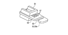
- FIG. 2A is a diagram illustrating that a cable is connected to a board member provided inside the control connector unit.
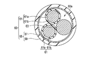
- 2B is a cross-sectional view of the cable taken along line 2B-2B shown in FIG. 2A.
- 2C is a cross-sectional view of the cable taken along line 2C-2C shown in FIG. 2A.
- FIG. 2D is a diagram for explaining that the internal conductor and the drain cable are connected to the cable-side connector portion via the terminal portion.
- FIG. 3 shows a first modification of the first embodiment, and is a diagram showing a cable wound around the relaxation portion of the first modification.
- FIG. 3 shows a first modification of the first embodiment, and is a diagram showing a cable wound around the relaxation portion of the first modification.
- FIG. 4A is a diagram illustrating a second modification of the first embodiment and a cable wound around a relaxation portion of the second modification.
- FIG. 4B is a side view showing that the cable shown in FIG. 4A is wound around the pin portion.
- FIG. 5A shows a third modification of the first embodiment, and includes a board member that has a relaxation part of the third modification and is provided inside the light connector part, and a core wire connected to the board member
- FIG. 5B is a perspective view of the substrate member shown in FIG. 5A.
- FIG. 6 is a diagram illustrating a fourth modification of the first embodiment and illustrating that a cable is connected to a board member provided inside the operation unit.
- FIG. 7A is a diagram illustrating a state in which cables are connected to each other according to the second embodiment of the present invention, and includes three cable-side connector portions, and one cable-side connector portion is connected to two cable sides. It is a figure which shows the state connected to the connector part.
- FIG. 7B is a diagram illustrating a state in which cables are connected to each other according to the second embodiment of the present invention, and includes four cable side connector portions, and one cable side connector portion is one cable side. It is a figure which shows the state connected to the connector part.
- an endoscope 10 includes an elongated insertion portion 20 that is inserted into a body cavity of a patient, and an operation portion 30 that is connected to a proximal end portion of the insertion portion 20 and operates the endoscope 10.
- the insertion portion 20 includes a distal end hard portion 21, a bending portion 23, and a flexible tube portion 25 from the distal end side of the insertion portion 20 toward the proximal end portion side of the insertion portion 20.
- the proximal end portion of the distal end hard portion 21 is connected to the distal end portion of the bending portion 23, and the proximal end portion of the bending portion 23 is connected to the distal end portion of the flexible tube portion 25.
- the distal end hard portion 21 includes an electronic component unit (not shown) provided inside the distal end hard portion 21.
- the electronic component unit includes, for example, a light emitting element such as an LED provided in the illumination unit and an image pickup element such as a CMOS provided in the imaging unit.
- the operation unit 30 is connected to a bend part 31 from which the flexible tube part 25 extends and a proximal end part of the bend part 31, and is operated by an operator who operates the endoscope 10.
- a grip portion (main body portion) 33 to be gripped and a universal cord 35 connected to the grip portion 33 in a direction different from the flexible tube portion 25 are provided.
- the grasping portion 33 has various functions of the treatment instrument insertion portion 33 a, a bending operation portion 33 b that performs a bending operation of the bending portion 23, and the endoscope 10 such as air supply / water supply / suction / photographing. And a switch portion 33c that is operated when operating.
- the universal cord 35 has a connector portion 37 that is connected to a peripheral device (not shown) of the endoscope 10.
- the connector unit 37 includes a light connector unit 37a that is detachably attached to a light source device (not shown) as a peripheral device, and a control connector unit 37b that is detachable to a control device (not shown) as a peripheral device.
- the light connector portion 37 a is provided at the end portion of the universal cord 35.
- a cord 35a is connected to the peripheral surface of the write connector portion 37a, and the cord 35a extends from the peripheral surface of the write connector portion 37a to the side of the light connector portion 37a.
- the control connector portion 37b is provided at the end of the cord 35a.
- the endoscope 10 includes a substrate member 50 provided in the endoscope 10 and cables 60 and 80 provided in the endoscope 10.
- Each of the cables 60 and 80 has a distal end portion that is indirectly connected to the board member 50 via a cable-side connector portion 71 described later, and a base end portion (not shown) that is connected to the electronic component unit.
- the board member 50 is provided inside the connector portion 37, for example.
- the board member 50 can transmit a signal for operating the endoscope 10.
- the connector part 37 is the control connector part 37b, for example.
- the substrate member 50 transmits a predetermined signal and a predetermined power between the substrate member 50 and a peripheral device (not shown) and between the substrate member 50 and the cables 60 and 80, and the predetermined signal supplied from the peripheral device. And it functions as an electric board that supplies predetermined power to the cables 60 and 80.
- the board member 50 can be electrically connected to a connection member (not shown) such as a control device as a peripheral device.
- the signal for operating the endoscope 10 is, for example, a signal included in the predetermined signal described above, and is a signal that is transmitted to the electronic component unit and controls the electronic component unit.
- the board member 50 has a board side connector part 51 connected to the cable side connector part 71.
- the cable side connector part 71 functions as a housing part.
- Cables 60 and 80 as shown in FIG. 2A are arranged inside the endoscope 10 from the distal end hard portion 21 to the connector portion 37.
- the cables 60 and 80 transmit predetermined signals and predetermined power between the cables 60 and 80 and the board member 50 and between the cables 60 and 80 and the electronic component unit, and are supplied from the board member 50. It functions as an electric cable for supplying the signal and predetermined power to the electronic component unit.
- the cables 60 and 80 are illumination cables for the lighting unit
- the electronic component unit transmits a predetermined signal and a predetermined power from the cables 60 and 80 and emits light.
- the cables 60 and 80 are imaging cables for the imaging unit
- the electronic component unit is transmitted with a predetermined signal and a predetermined power from the cables 60 and 80 and images.
- a signal may be transmitted between the connector unit 37 and the electronic component unit.
- the cables 60 and 80 may be electrically connected to another cable (not shown) that is electrically connected to the electronic component unit, for example, via a connector portion (not shown).
- a signal is transmitted between the connector part 37 and an electronic component unit via the cables 60 and 80 and another cable.
- Another cable (not shown) is appropriately arranged along the longitudinal axis.
- the electronic component unit has a light emitting element of the illumination unit and an image pickup element of the image pickup unit arranged in the distal end hard portion 21.
- the cable 60 is provided on the outside of the plurality of core wire portions 61, the drain cable 63, the core wire portion 61 and the drain cable 63, and the outer periphery and the drain of the plurality of core wire portions 61. And a cover portion 65 that collectively covers the outer periphery of the cable 63.
- the drain cable 63 is preferably twisted together with the core wire portion 61. As shown in FIG.
- the cover portion 65 is provided outside the core wire portion 61 and the drain cable 63, and a shield member 67 (total shield) that covers the plurality of core wire portions 61 and the drain cable 63 together, It has an outer skin (insulating sheath) 69 that is provided outside the shield member 67 and covers the outer periphery of the shield member 67.
- the shield member 67 has conductivity, and is made of metal, for example.
- the shield member 67 covers the outer periphery of the core wire portion 61 and the outer periphery of the drain cable.
- the outer skin 69 has electrical insulation and is made of, for example, resin.
- One end of the cable 60 is provided with one cable side connector 71.
- the core portion of the cable 80, the inner conductor, the cover member, the drain cable, the cover portion, the shield member, and the outer sheath are referred to as the core portion 81, the inner conductor 81a, the cover member 81b, the drain cable 83, the cover portion 85, and the shield. They are referred to as member 87 and outer skin 89.
- the cable 60 has, for example, one unit 60a, and one unit 60a has two core portions 61 and one drain cable 63.
- the cable 80 is of a different type from the cable 60, and includes, for example, two units 80a.
- One unit 80a includes two core portions 81 and one drain. And a cable 83.
- the cable 80 has two pairs (four) of core wire portions 81 and two drain cables 83.
- One cable side connector 71 is shared by the two units 80a.
- the one cable side connector portion 71 is a separate body from the cable side connector portion 71 on the cable 60 side.
- Core 61 and drain cable 63 As shown in FIGS. 2A and 2B, in this embodiment, for example, two core wire portions 61 are provided in one cable 60, but there is no particular limitation as long as a plurality of core wire portions 61 are provided.
- the core wire part 61 has flexibility, for example.
- the core wire portion 61 is provided inside the shield member 67.
- the core wire portion 61 is electrically connected to the board member 50 and can transmit a signal to the board member 50, for example.
- the outer periphery of the core wire part 61 has electrical insulation. As shown in FIG. 2B, for example, the core part 61 is provided on the outer side of the inner conductor 61a and the inner conductor 61a that is electrically connected to the board member 50 so as to transmit signals to the board member 50. And a cover member (insulating sheath) 61b that covers the outer periphery of the inner conductor 61a.
- the inner conductor 61a is electrically connected to the board member 50 and the electronic component unit. Thereby, the internal conductor 61a transmits a predetermined signal between the cable 60 and the board member 50 and between the cable 60 and the electronic component unit, and the predetermined electric power supplied from the board member 50 is transmitted to the electronic component unit.
- the inner conductor 61a includes a core wire bundle.
- the core wire bundle is a bundle formed by twisting a plurality of strands with respect to each other.
- the cover member 61b has a cylindrical shape so that the inner conductor 61a is provided inside the cover member 61b, and the outer peripheral surface of the inner conductor 61a is in close contact with the inner peripheral surface of the cover member 61b.
- the cover member 61b is provided over the entire length of the inner conductor 61a.
- the inner conductor 61a has conductivity, and is made of, for example, metal.
- the cover member 61b has electrical insulation and is made of, for example, resin.
- the cover member 61b electrically insulates the inner conductor 61a from metal parts provided outside the inner conductor 61a such as the drain cable 63 and the shield member 67, for example.
- the drain cable 63 has substantially the same outer diameter as the core wire portion 61. Since the cover member 61b is thinner than the inner conductor 61a, the drain cable 63 can be regarded as having the same outer diameter as the inner conductor 61a.
- the drain cable 63 has conductivity, and is made of, for example, metal.
- the drain cable 63 is provided inside the shield member 67.
- the drain cable 63 is inserted through the shield member 67.
- the drain cable 63 is electrically connected to the shield member 67 so that the potential of the drain cable 63 is the same as the potential of the shield member 67. For this reason, the outer peripheral surface of the drain cable 63 is connected to the inner peripheral surface of the shield member 67.
- the entire drain cable 63 is preferably electrically connected continuously from the distal end to the proximal end of the shield member 67, but this is not always necessary.
- at least a part of the outer peripheral surface of the drain cable 63 may be electrically connected to at least a part of the inner peripheral surface of the shield member 67. Therefore, the connection between the drain cable 63 and the shield member 67 may be point contact or surface contact.
- the drain cable 63 is not necessarily provided over the entire length of the shield member 67. It is only necessary that the drain cable 63 can be electrically connected to the cable-side connector 71 and the drain cable 63 is electrically connected to the shield member 67.
- the drain cable 63 may be provided only at the tip of the shield member 67 inside the shield member 67 so that the tip of the drain cable 63 is exposed from the tip of the shield member 67.
- Such a drain cable 63 electrically connects the shield member 67 to the substrate member 50.
- the drain cable 63 is electrically separated from the internal conductor 61a by the cover member 61b.
- the distal end portion of the core wire portion 61 and the distal end portion of the drain cable 63 extend along the longitudinal axis direction of the cable 60 from the distal end portion of the shield member 67 and the distal end portion of the outer skin 69. It is exposed (projected) toward the cable side connector portion 71.
- the tip of the shield member 67 in the longitudinal axis direction of the cable 60 is such that the tip of the core wire portion 61 and the tip of the drain cable 63 are in contact with the tip of the shield member 67 and the tip of the outer skin 69. It shows that it protrudes ahead toward the cable side connector part 71 from the front-end
- the cable 60 so that the tip of the core wire 61 and the tip of the drain cable 63 are exposed from the tip of the shield member 67 and the tip of the outer skin 69.
- the front end surface of 60 is cut. Specifically, the tip of the shield member 67 and the tip of the outer skin 69 are removed so that the tip of the core wire 61 and the tip of the drain cable 63 are exposed.
- the length of the exposed tip portion of the core wire portion 61 is substantially the same as the length of the exposed tip portion of the drain cable 63.
- the exposed tip portion of the core wire portion 61 and the exposed tip portion of the drain cable 63 are separated from each other and also electrically separated.
- the tip portion of the internal conductor 61 a is directed from the tip portion of the cover member 61 b toward the cable side connector portion 71 in the longitudinal axis direction of the core wire portion 61. Exposed.
- the exposed tip of the inner conductor 61a and the exposed tip of the drain cable 63 have a terminal portion 73 for electrical contact.
- the cable 60 is electrically connected to the cable side connector part 71 by inserting the terminal part 73 into an insertion port (not shown) of the cable side connector part 71.
- the width of the cable side connector portion 71 is larger than that of the core wire portion 61, the drain cable 63, and the cable 60.
- the cable side connector part 71 has electric resistance.
- the exposed end of the drain cable 63 is covered with a cover member (not shown).
- the cover member has electrical insulation and is made of, for example, resin.
- the cover member has, for example, a heat shrinkable tube.
- the drain cable 63 is insulated from a metal component (not shown) provided around the cable 60 by the cover member.
- the thickness of the cover member is substantially the same as the thickness of the cover member 61b.
- the cover member may cover the exposed end portion of the core wire portion 61 and the end portion of the drain cable 63 together.
- the cover member collectively covers the exposed distal end portion of the core wire portion 61, the distal end portion of the drain cable 63, the distal end portion of the shield member 67, the distal end portion of the outer skin 69, and the cable side connector portion 71. May be.
- the shield member 67 as shown in FIGS. 2A, 2B, and 2D is formed by twisting a plurality of metal strands against each other.
- the shield member 67 has a net-like cylindrical shape, for example, a cylindrical shape.
- the shield member 67 covers the outer periphery of the core wire portion 61 and the outer periphery of the shield member 67 so that the core wire portion 61 and the drain cable 63 are provided inside the shield member 67.
- the shield member 67 electrically protects the core wire portion 61 so that noise generated from an external device (not shown) such as an endoscopic high-frequency treatment instrument and an electric knife does not affect the core wire portion 61 electrically.
- the shield member 67 electrically shields the core wire portion 61 from the outside in order to prevent a high-frequency leakage current generated from an external device or the like from electrically affecting the core wire portion 61.
- the external device is inserted from the treatment instrument insertion portion 33a and passes through a channel (not shown) that is continuous with the treatment instrument insertion portion 33a.
- the shield member 67 prevents a signal transmitted by the inner conductor 61 a of the core wire portion 61 from leaking to the outside of the core wire portion 61.
- the shield member 67 is provided over the entire length of the inner conductor 61a. Specifically, the shield member 67 is provided from the distal end hard portion 21 to the connector portion 37, and is grounded to the GND of the control device, for example, via the connector portion 37.
- the distal end portion of the shield member 67 is exposed from the distal end portion of the outer skin 69 toward the cable-side connector portion 71 in the longitudinal axis direction of the shield member 67 in this embodiment.
- the tip of the shield member 67 protrudes forward from the tip of the outer skin 69 toward the cable-side connector 71 in the longitudinal axis direction of the shield member 67 with respect to the tip of the outer skin 69. Indicates.
- the front end surface of the outer skin 69 in the cable 60 is cut so that the front end portion of the shield member 67 is exposed from the front end portion of the outer skin 69.
- the tip of the outer skin 69 is removed so that the tip of the shield member 67 is exposed.
- This cutting is performed simultaneously with the cutting for exposing the tip of the core wire part 61, for example.
- the distal end portion of the shield member 67 may be positioned at the same position as the distal end portion of the outer skin 69, or may be folded back so as to overlap the outer peripheral surface of the distal end portion of the outer skin 69.
- the outer skin 69 has a cylindrical shape, for example, a cylindrical shape so that the core wire portion 61, the drain cable 63, and the shield member 67 are provided inside the outer skin 69.
- the outer skin 69 is formed as a tube.
- the inner diameter of the outer skin 69 is substantially the same as the outer diameter of the shield member 67 so that the inner peripheral surface of the outer skin 69 is in close contact with the outer peripheral surface of the shield member 67.
- the outer diameter of the drain cable 63 is substantially the same as the outer diameter of the core wire portion 61.
- the tip end portion of the drain cable 63 is connected to the inner conductor 61a.
- the insertion port portion of the cable side connector portion 71 into which the distal end portion is inserted can be used.
- the internal conductor 61a and the drain cable 63 can share the common cable side connector portion 71.
- the inner conductor 61a and the drain cable 63 can be appropriately disposed in the housing of the cable-side connector portion 71.
- the kind of the cable side connector part 71 ie, a shape, and a magnitude
- the tip of the shield member 67 is directly inserted into the insertion port of the cable side connector 71.
- the distal end portion of the shield member 67 is cylindrical and the outer diameter of the distal end portion is large, the distal end portion of the shield member 67 cannot be inserted into the insertion port portion of the cable side connector portion 71.
- the narrow end portion of the drain cable 63 that is electrically connected to the shield member 67 and is thinner than the shield member 67 is used.
- the thin tip end portion of the drain cable 63 having an outer diameter substantially the same as the outer diameter of the core wire portion 61 is easily inserted into the insertion port portion of the cable-side connector portion 71. Therefore, by using the drain cable 63, the shield member 67 is easily and reliably electrically connected to the board member 50 via the drain cable 63 and the cable side connector portion 71. Assemblability in electrical connection with 50 is improved.
- the terminal portion 73 is not directly fixed to the board member 50 by solder.
- the cable-side connector 71 and the board-side connector 51 having a width larger than the inner conductor 61a, the drain cable 63, and the terminal 73 are used, and the cable-side connector as shown in FIG. 2A. 71 is connected to the board-side connector portion 51.
- This connection includes, for example, fitting one of the board-side connector part 51 and the cable-side connector part 71 into the other, or connecting one to the other.
- the electrical connection work of the cable 60 to the board member 50 is simply performed by simply connecting the cable side connector part 71 to the board side connector part 51.
- the connecting portion includes the tip end portion of the core wire portion 61 exposed from the shield member 67, the tip end portion of the drain cable 63 exposed from the shield member 67, the cable side connector portion 71, and the board side connector portion 51. Including.
- solder for the electrical connection work of the cable 60 to the board member 50.
- the complexity of the connection work accompanying solder is eliminated, the poor assemblability is eliminated, the hard part generated by the solder is eliminated, and the hard part is lengthened. Further, it is eliminated that the connecting portion becomes large and thick due to the solder, and that the arrangement position of the connecting portion is limited by the solder.
- the thickness of the cover member is substantially the same as the thickness of the cover member 61b. For this reason, even if the cover member covers the distal end portion of the drain cable 63, the connection portion including the distal end portion of the core wire portion 61 exposed from the shield member 67 and the exposed distal end portion of the drain cable 63 is thick. Is prevented. In particular, the distal end portion of the core wire portion 61 and the distal end portion of the drain cable 63 are surely thinner than the cable side connector portion 71 and the board side connector portion 51. Since the cover member only needs to cover at least the tip of the drain cable 63, the operation of attaching the cover member is simply performed.
- the shield member 67 is not directly electrically connected to the board member 50, but is electrically connected to the shield member 67.
- the drain cable 63 is electrically connected to the board member 50 via the cable side connector part 71 and the board side connector part 51.
- the shield member 67 is indirectly electrically connected to the substrate member 50 by the drain cable 63. For this reason, the assemblability in the electrical connection between the shield member 67 and the board member 50 is improved.
- the shield member 67 can be easily and reliably electrically connected to the substrate member 50 via the drain cable 63. Thereby, in this embodiment, the assembly property in the electrical connection of the shield member 67 and the board
- the outer diameter of the drain cable 63 is substantially the same as the outer diameter of the core wire portion 61.
- tip part of the drain cable 63 can be inserted in the insertion port part of the cable side connector part 71 in which the front-end
- substrate side connector part 51 which are common with respect to the internal conductor 61a and the drain cable 63 can be utilized. Since the cable side connector part 71 and the board side connector part 51 can be used, the electrical connection work of the cable 60 to the board member 50 can be easily performed, the assembling property of the connection can be improved, and the connection work can be carried out with one touch. The connection portion can be prevented from becoming large and long, and the durability of the connection portion can be ensured.
- the drain cable 63 electrically connected to the shield member 67 is used inside the shield member 67, and solder is used for electrical connection work. There is no need to use it. For this reason, the complexity of the connection work accompanying solder can be eliminated, the poor assemblability can be eliminated, the hard part can be prevented from being generated by the solder, and the hard part can be prevented from becoming longer. Further, it is possible to eliminate the large and thick connection portion due to the solder, and it is possible to prevent the arrangement position of the connection portion from being limited by the solder.
- the thickness of the cover member is substantially the same as the thickness of the cover member 61b. For this reason, even if the cover member covers the distal end portion of the drain cable 63, the connection portion including the distal end portion of the core wire portion 61 exposed from the shield member 67 and the exposed distal end portion of the drain cable 63 is thick. Can be prevented.
- the tip end portion of the core wire portion 61 and the tip end portion of the drain cable 63 can be made thinner than the cable side connector portion 71 and the board side connector portion 51 with certainty.
- the cover member since the cover member only needs to cover at least the tip of the drain cable 63, the operation of attaching the cover member can be performed simply. Since one cover member is provided in one cable 60, the attachment work can be performed for each cable 60, and the attachment work can be easily performed.
- the attaching operation is performed after the cable-side connector portion 71 is connected to the board-side connector portion 51, the complexity of the attaching operation increases. For this reason, the attaching operation is performed before the cable-side connector portion 71 is connected to the board-side connector portion 51 and is not performed on the board member 50. Therefore, the mounting operation can be performed in a state where complexity is eliminated.
- the board member 50 is provided in the connector portion 37, but it is not necessary to be limited to this.
- the cable side connector portion 71 is provided inside the bend preventing portion 31 and the board member 50 including the board side connector portion 51. May be provided inside the proximal end portion of the insertion portion 20.
- the location of the connection portion is not particularly limited.
- the board member 50 includes a relaxation portion 53 that reduces a load acting on a connection portion between the cable 60 and the board member 50 as the cable 60 moves.
- the substrate member 50 has a cutout portion 55 formed by cutting out a part of the substrate member 50.
- the relaxing part 53 has a wound part 50a around which the cable 60 is wound.
- the wound part 50 a is a part of the substrate member 50 on which a part of the cable 60 that has passed through the notch part 55 is wound.
- the number of windings of the cable 60 around the wound portion 50a is not particularly limited. It is preferable that the cable 60 is wound around the wound portion 50a in a state where the cable 60 is loosened to an appropriate extent.
- the cable 60 may be wound around the wound portion 50a in a tightly wound state.
- a portion of the cable 60 that winds the wound portion 50a is a midway portion that exists between the distal end portion and the proximal end portion of the cable 60, and is a portion that excludes the connection portion.
- the notch 55 is formed by the substrate member 50 penetrating in the thickness direction of the substrate member 50, and the substrate member 50 being notched in the width direction of the substrate member 50.
- the play amount only increases or decreases as the cable 60 moves. For this reason, the relaxing part 53 can relieve the load acting on the cable 60.
- the mitigation part 53 does not need to be limited to the content demonstrated in the 1st modification.
- the wound portion of the relaxing portion 53 has a pin portion 53 b that winds a part of the cable 60.
- the pin part 53b is provided in the board member 50, for example, for checking the state of the electric circuit mounted on the board member 50.
- the board member 50 When the board member 50 is provided inside the light connector portion 37 a, the board member 50 has a direct electrical connection between the distal end portion of the core wire portion 61 exposed from the distal end portion of the cover portion 65 and the distal end portion of the drain cable 63. It functions as a mounting board connected to. Specifically, the inner conductor 61a disposed on the right side in FIG. 5A and exposed from the cover member 61b is directly connected to the plurality of electrodes 57 (see FIG. 5B) of the board member 50 by, for example, solder. The shield member 67 itself arranged on the right side of FIG. 5A is not directly electrically connected to the electrode 57, but the drain cable 63 arranged on the right side of FIG.
- the shield member 67 can be easily and reliably electrically connected to the substrate member 50 via the drain cable 63 as compared with the case where the shield member 67 is directly electrically connected to the electrode 57.
- the distal end portion of the core wire portion 61 and the distal end portion of the drain cable 63 are electrically insulated from each other.
- the cable 60 (see the cable 60 arranged on the right side in FIG. 5A) connected in advance to the board member 50 is, for example, the inside of the insertion portion 20 and the universal cord 35. Provided inside.
- the cable 60 including the exposed core wire portion 61 moves. This movement is caused by twisting of the cable 60, bending of the cable 60, bending of the straight cable 60, straightening of the bent cable 60, pulling of the cable 60, or pulling of the cable 60. Is pressed. Due to this movement, there is a possibility that a load is generated at a connection portion between the core wire portion 61 (inner conductor 61a) and the board member 50.
- the board member 50 includes a relaxation portion 53 that reduces the load acting on the connection portion between the core wire portion 61 and the board member 50 as the core wire portion 61 moves.
- the substrate member 50 has a cutout portion 55 formed by cutting out a part of the substrate member 50.
- the relaxing part 53 has a wound part 50a around which the core part 61 is wound.
- the wound portion 50 a is a portion of the substrate member 50 that is exposed from the tip portion of the cover portion 65 and on which a part of the core wire portion 61 that has passed through the cutout portion 55 is wound.
- the number of windings of the core wire part 61 around the wound part 50a is not particularly limited.
- the core wire portion 61 is preferably wound around the wound portion 50a in a state where the core wire portion 61 is loosened to an appropriate extent.
- the cable 60 may be wound around the wound portion 50a in a tightly wound state.
- a portion of the core wire portion 61 that winds the wound portion 50a is a midway portion that exists between the distal end portion and the proximal end portion of the core wire portion 61, and is a portion that excludes the connection portion.
- the notch 55 is formed by the substrate member 50 penetrating in the thickness direction of the substrate member 50, and the substrate member 50 being notched in the width direction of the substrate member 50.
- the inner conductor 61a exposed from the cover member 61b may wind the wound portion 50a.
- the core wire portion 61 is directly fixed to the substrate member 50 by winding the wound portion 50a.
- the drain cable 63 is directly fixed to the substrate member 50.
- the drain cable 63 may be directly fixed to the substrate member 50 by winding the wound portion 50a.
- the load applied to the electrical connection portion between the core wire portion 61 and the board member 50 can be reduced.
- the play amount only increases or decreases as the core wire portion 61 moves. For this reason, the relaxing part 53 can relieve the load acting on the core wire part 61.
- a cover member (not shown) includes a tip end portion of the core wire portion 61 exposed from the cover portion 65, a tip end portion of the drain cable 63 exposed from the cover portion 65, a cutout portion 55, and a wound portion 50a.
- the cutout portion 55 and the peripheral portion of the wound portion 50a are covered.
- the peripheral part may include the periphery of the distal end portion of the core wire portion 61 and the periphery of the distal end portion of the drain cable 63.
- the cover member has electrical insulation and is made of, for example, resin.
- the cover member insulates the tip end portion of the core wire portion 61, the tip end portion of the drain cable 63, and the peripheral portion from the metal parts provided in the periphery thereof.
- the cover member has, for example, a heat shrinkable tube.
- the board member 50 is provided with a board-side connector portion 51.
- the board side connector part 51 is electrically connected to the electrode 57.
- the board side connector part 51 is connected to a cable side connector part 71 arranged on the left side of FIG. 5A.
- the cable side connector portion 71 is connected to the other cable 60 (see the cable 60 arranged on the left side of FIG. 5A) provided at the end of the light connector portion 37a.
- the drain cable 63 of one cable 60 arranged on the right side of FIG. 5A is electrically fixed to the substrate member 50 via the electrode 57, so that the shield member 67 of one cable 60 is arranged on the left side of FIG. 5A.
- the board member 50 functions as a relay board that electrically connects the cables 60 to each other.
- the board member 50 as shown in FIG. 6 may be provided in the operation unit 30 and may function as a relay board that electrically connects the cables 60 and 80 and the cables 80, for example.
- the cable side connector part 71 is detachable from the board member 50.
- the substrate member 50 can be provided at various positions inside the endoscope 10.
- the cable 80 arranged on the right side of FIG. 7A has, for example, two units 80a.
- Each unit 80a has, for example, two core portions 81 and one drain cable 83.
- a female cable-side connector 71a connected to the cable 80 may be shared by the two units 80a. For this reason, one female type cable side connector part 71a is provided. As shown in FIG. 7A, the female cable side connector portion 71a is connected to two male cable side connector portions 71b connected to the two cables 60, respectively.
- a female cable-side connector 71a connected to the cable 80 may be provided in each unit 80a.
- two female cable side connector portions 71a are provided.
- each of the female cable-side connector portions 71a is connected to two male-type cable-side connector portions 71b connected to the two cables 60, respectively.
- one connection portion may be arranged so as to be shifted in the longitudinal axis direction of the cable 60 with respect to the other connection portion. Thereby, it can prevent that a connection part periphery becomes thick.
- the exposed end portion of the drain cable 63 is covered with a cover member (not shown).
- the cover member has electrical insulation and is made of, for example, resin.
- the cover member has, for example, a heat shrinkable tube.
- the drain cable 63 is insulated from a metal component (not shown) provided around the cable 60 by the cover member.
- the cable 60 may be connected to, for example, an imaging unit in the electronic component unit via the cable side connector portion 71.
- the core wire portion 61 is electrically connected to, for example, an electrical assembly included in the electronic component unit.
- the present invention is not limited to the above-described embodiment as it is, and can be embodied by modifying the constituent elements without departing from the scope of the invention in the implementation stage. Further, various inventions can be formed by appropriately combining a plurality of constituent elements disclosed in the embodiment.
Landscapes
- Health & Medical Sciences (AREA)
- Life Sciences & Earth Sciences (AREA)
- Physics & Mathematics (AREA)
- Surgery (AREA)
- Optics & Photonics (AREA)
- Engineering & Computer Science (AREA)
- Biomedical Technology (AREA)
- General Health & Medical Sciences (AREA)
- Pathology (AREA)
- Nuclear Medicine, Radiotherapy & Molecular Imaging (AREA)
- Biophysics (AREA)
- Heart & Thoracic Surgery (AREA)
- Medical Informatics (AREA)
- Molecular Biology (AREA)
- Animal Behavior & Ethology (AREA)
- Radiology & Medical Imaging (AREA)
- Public Health (AREA)
- Veterinary Medicine (AREA)
- Astronomy & Astrophysics (AREA)
- General Physics & Mathematics (AREA)
- Microelectronics & Electronic Packaging (AREA)
- Endoscopes (AREA)
- Instruments For Viewing The Inside Of Hollow Bodies (AREA)
Abstract
An endoscope (10) has a substrate member (50) and a cable (60) which has a core wire section (61), a shield member (67), and a drain cable (63). The drain cable (63) is electrically conductive and has substantially the same outer diameter as the core wire section (61). The drain cable (63) is electrically connected to the shield member (67) to electrically connect the shield member (67) to the substrate member (50) and is electrically separated from the core wire member (61).
Description
本発明は、ケーブルを内部に有する内視鏡に関する。
The present invention relates to an endoscope having a cable inside.
一般的に、内視鏡の内部に備えられるケーブルは、複数の芯線部と、芯線部の外側に備えられ、複数の芯線部をまとめてカバーするシールド部材(総合シールド)と、シールド部材の外側に備えられ、シールド部材をカバーする外皮とを有する。シールド部材は、複数の金属製の素線同士が互いに対して撚り合わさることによって、形成される。
Generally, a cable provided in an endoscope is provided with a plurality of core wire portions, a shield member (general shield) that covers a plurality of core wire portions together, and an outside of the shield member. And an outer skin that covers the shield member. The shield member is formed by twisting a plurality of metal strands against each other.
2本のケーブル同士が互いに対して接続される際、一方のケーブルにおいて、シールド部材の端部は芯線部の端部の側方に引っ張られ束ねられ、これにより芯線部の端部がシールド部材の端部から露出する。この点は、他方のケーブルについても同様である。そして芯線部同士は半田によって互いに対して接続されることによって、第1接続部分が形成される。第1接続部分は、第1接続部分の保護と第1接続部分の周辺に備えられる図示しない金属部品に対する絶縁とのために熱収縮チューブによってカバーされる。シールド部材同士も第1接続部分の側方にて半田によって互いに対して接続されることによって、第2接続部分が形成される。第2接続部分は、第2接続部分の保護と第2接続部分の周辺に備えられる図示しない金属部品に対する絶縁とのために熱収縮チューブによってカバーされる。最後に、芯線部における第1接続部分と、シールド部材における第2接続部分とは、これら第1,2接続部分の保護と第1,2接続部分同士の束縛と第1,2接続部分の周辺に備えられる図示しない金属部品に対する絶縁とのために、熱収縮チューブによってまとめてカバーされる。
When two cables are connected to each other, in one cable, the end portion of the shield member is pulled and bundled to the side of the end portion of the core wire portion, whereby the end portion of the core wire portion is connected to the shield member. Exposed from the edge. This also applies to the other cable. The core wire portions are connected to each other by solder to form a first connection portion. The first connection part is covered by a heat shrinkable tube for protection of the first connection part and insulation against a metal part (not shown) provided around the first connection part. The shield members are also connected to each other by solder on the side of the first connection portion, thereby forming the second connection portion. The second connection part is covered by a heat shrinkable tube for protection of the second connection part and insulation against a metal part (not shown) provided around the second connection part. Finally, the first connection portion in the core wire portion and the second connection portion in the shield member are the protection of the first and second connection portions, the binding between the first and second connection portions, and the periphery of the first and second connection portions. Are collectively covered by a heat-shrinkable tube for insulation against metal parts (not shown) provided in the case.
例えば特許文献1に開示されている内視鏡において、芯線部同士は、接続部材に実装されたコネクタ部によって、互いに電気的に接続される。
For example, in the endoscope disclosed in Patent Document 1, the core wire portions are electrically connected to each other by a connector portion mounted on a connection member.
ケーブルが内視鏡のような細い部材の内部に備えられることを考慮すると、シールド部材同士の半田による接続作業は煩雑であり、この接続の組立性が悪い。シールド部材同士の接続部分が多いほど、煩雑さは増大し、組立性は悪くなる。半田によって、硬質部分が発生し、硬質部分が長くなり、接続部分は大きく且つ太くなり、接続部分の配置位置が限定される要因となる。接続部分を小型化するためにケーブルの各構成物を細径化及び薄肉化すると、接続部分の耐久性が低下し、接続作業は煩雑となり、組立性が悪くなり得る。この点は、シールド部材と基板部材との電気的な接続についても同様である。
Considering that the cable is provided inside a thin member such as an endoscope, the connecting work of the shield members by soldering is complicated, and the assemblability of this connection is poor. As the number of connecting portions between the shield members increases, the complexity increases and the assemblability deteriorates. A hard part is generated by solder, the hard part becomes longer, the connection part becomes larger and thicker, and the arrangement position of the connection part is limited. When the diameter and thickness of each component of the cable are reduced in order to reduce the size of the connecting portion, the durability of the connecting portion is lowered, the connecting work becomes complicated, and the assembling property may be deteriorated. This also applies to the electrical connection between the shield member and the substrate member.
本発明は、これらの事情に鑑みてなされたものであり、シールド部材と基板部材との電気的な接続における組立性を向上できる内視鏡を提供することを目的とする。
The present invention has been made in view of these circumstances, and an object of the present invention is to provide an endoscope that can improve assemblability in electrical connection between a shield member and a substrate member.
本発明の内視鏡の一態様は、内視鏡を操作するための信号を伝送可能な基板部材と、前記基板部材に接続されるケーブルであって、前記基板部材に電気的に接続され、前記信号を伝送可能であって、外周は電気絶縁性を有する芯線部と、前記芯線部の外周を被覆し、前記芯線部によって伝送される前記信号が前記芯線部の外部に漏れることを防止し、導電性を有するシールド部材と、導電性を有し、前記芯線部と略同一の外径を有しており、前記シールド部材に電気的に接続されて前記シールド部材を前記基板部材に電気的に接続し、前記芯線部に対して電気的に分離されたドレインケーブルと、を有するケーブルと、を具備する。
One aspect of the endoscope of the present invention is a board member capable of transmitting a signal for operating the endoscope and a cable connected to the board member, and is electrically connected to the board member, The signal can be transmitted, and an outer periphery covers an outer periphery of the core part having electrical insulation and the core part, and the signal transmitted by the core part is prevented from leaking outside the core part. A shield member having electrical conductivity, and having an electrical conductivity and substantially the same outer diameter as the core wire portion, and electrically connected to the shield member to electrically connect the shield member to the substrate member And a drain cable electrically connected to the core wire portion.
本発明によれば、シールド部材と基板部材との電気的な接続における組立性を向上できる内視鏡を提供できる。
According to the present invention, it is possible to provide an endoscope that can improve assemblability in electrical connection between the shield member and the substrate member.
以下、図面を参照して本発明の実施形態について詳細に説明する。
[第1の実施形態]
[構成]
図1と図2Aと図2Bと図2Cと図2Dとを参照して第1の実施形態について説明する。なお一部の図面では、図示の明瞭化のために、一部の部材の図示を省略または簡略している。 Hereinafter, embodiments of the present invention will be described in detail with reference to the drawings.
[First Embodiment]
[Constitution]
The first embodiment will be described with reference to FIGS. 1, 2A, 2B, 2C, and 2D. Note that in some drawings, illustration of some members is omitted or simplified for clarity of illustration.
[内視鏡10の構成1]
図1に示すように、内視鏡10は、患者の体腔内等に挿入される細長い挿入部20と、挿入部20の基端部に連結され、内視鏡10を操作する操作部30とを有する。 [Configuration 1 of Endoscope 10]
As shown in FIG. 1, anendoscope 10 includes an elongated insertion portion 20 that is inserted into a body cavity of a patient, and an operation portion 30 that is connected to a proximal end portion of the insertion portion 20 and operates the endoscope 10. Have
図1に示すように、内視鏡10は、患者の体腔内等に挿入される細長い挿入部20と、挿入部20の基端部に連結され、内視鏡10を操作する操作部30とを有する。 [Configuration 1 of Endoscope 10]
As shown in FIG. 1, an
[挿入部20]
図1に示すように、挿入部20は、挿入部20の先端部側から挿入部20の基端部側に向かって、先端硬質部21と、湾曲部23と、可撓管部25とを有する。先端硬質部21の基端部は湾曲部23の先端部に連結され、湾曲部23の基端部は可撓管部25の先端部に連結される。
先端硬質部21は、先端硬質部21の内部に備えられる図示しない電子部品ユニットを有する。電子部品ユニットは、例えば、照明ユニットに備えられるLEDなどの発光素子と、撮像ユニットに備えられるCMOSなどの撮像素子とを有する。 [Insertion section 20]
As shown in FIG. 1, theinsertion portion 20 includes a distal end hard portion 21, a bending portion 23, and a flexible tube portion 25 from the distal end side of the insertion portion 20 toward the proximal end portion side of the insertion portion 20. Have. The proximal end portion of the distal end hard portion 21 is connected to the distal end portion of the bending portion 23, and the proximal end portion of the bending portion 23 is connected to the distal end portion of the flexible tube portion 25.
The distal endhard portion 21 includes an electronic component unit (not shown) provided inside the distal end hard portion 21. The electronic component unit includes, for example, a light emitting element such as an LED provided in the illumination unit and an image pickup element such as a CMOS provided in the imaging unit.
図1に示すように、挿入部20は、挿入部20の先端部側から挿入部20の基端部側に向かって、先端硬質部21と、湾曲部23と、可撓管部25とを有する。先端硬質部21の基端部は湾曲部23の先端部に連結され、湾曲部23の基端部は可撓管部25の先端部に連結される。
先端硬質部21は、先端硬質部21の内部に備えられる図示しない電子部品ユニットを有する。電子部品ユニットは、例えば、照明ユニットに備えられるLEDなどの発光素子と、撮像ユニットに備えられるCMOSなどの撮像素子とを有する。 [Insertion section 20]
As shown in FIG. 1, the
The distal end
[操作部30]
図1に示すように、操作部30は、可撓管部25が延出している折れ止め部31と、折れ止め部31の基端部に連結され、内視鏡10を操作する術者によって把持される把持部(本体部)33と、可撓管部25とは異なる方向に把持部33に接続されるユニバーサルコード35とを有する。 [Operation unit 30]
As shown in FIG. 1, theoperation unit 30 is connected to a bend part 31 from which the flexible tube part 25 extends and a proximal end part of the bend part 31, and is operated by an operator who operates the endoscope 10. A grip portion (main body portion) 33 to be gripped and a universal cord 35 connected to the grip portion 33 in a direction different from the flexible tube portion 25 are provided.
図1に示すように、操作部30は、可撓管部25が延出している折れ止め部31と、折れ止め部31の基端部に連結され、内視鏡10を操作する術者によって把持される把持部(本体部)33と、可撓管部25とは異なる方向に把持部33に接続されるユニバーサルコード35とを有する。 [Operation unit 30]
As shown in FIG. 1, the
[把持部33]
図1に示すように、把持部33は、処置具挿入部33aと、湾曲部23を湾曲操作する湾曲操作部33bと、送気・送水・吸引・撮影等の内視鏡10の各種機能を操作する際に操作されるスイッチ部33cとを有する。 [Grip part 33]
As shown in FIG. 1, the grasping portion 33 has various functions of the treatmentinstrument insertion portion 33 a, a bending operation portion 33 b that performs a bending operation of the bending portion 23, and the endoscope 10 such as air supply / water supply / suction / photographing. And a switch portion 33c that is operated when operating.
図1に示すように、把持部33は、処置具挿入部33aと、湾曲部23を湾曲操作する湾曲操作部33bと、送気・送水・吸引・撮影等の内視鏡10の各種機能を操作する際に操作されるスイッチ部33cとを有する。 [Grip part 33]
As shown in FIG. 1, the grasping portion 33 has various functions of the treatment
[ユニバーサルコード35]
図1に示すように、ユニバーサルコード35は、内視鏡10の図示しない周辺装置に接続されるコネクタ部37を有する。コネクタ部37は、周辺装置としての図示しない光源装置に着脱自在なライトコネクタ部37aと、周辺装置としての図示しない制御装置に着脱自在な制御コネクタ部37bとを有する。ライトコネクタ部37aは、ユニバーサルコード35の端部に備えられる。ライトコネクタ部37aの周面にはコード35aが接続されており、コード35aはライトコネクタ部37aの周面からライトコネクタ部37aの側方に延びている。制御コネクタ部37bは、コード35aの端部に備えられる。 [Universal code 35]
As shown in FIG. 1, theuniversal cord 35 has a connector portion 37 that is connected to a peripheral device (not shown) of the endoscope 10. The connector unit 37 includes a light connector unit 37a that is detachably attached to a light source device (not shown) as a peripheral device, and a control connector unit 37b that is detachable to a control device (not shown) as a peripheral device. The light connector portion 37 a is provided at the end portion of the universal cord 35. A cord 35a is connected to the peripheral surface of the write connector portion 37a, and the cord 35a extends from the peripheral surface of the write connector portion 37a to the side of the light connector portion 37a. The control connector portion 37b is provided at the end of the cord 35a.
図1に示すように、ユニバーサルコード35は、内視鏡10の図示しない周辺装置に接続されるコネクタ部37を有する。コネクタ部37は、周辺装置としての図示しない光源装置に着脱自在なライトコネクタ部37aと、周辺装置としての図示しない制御装置に着脱自在な制御コネクタ部37bとを有する。ライトコネクタ部37aは、ユニバーサルコード35の端部に備えられる。ライトコネクタ部37aの周面にはコード35aが接続されており、コード35aはライトコネクタ部37aの周面からライトコネクタ部37aの側方に延びている。制御コネクタ部37bは、コード35aの端部に備えられる。 [Universal code 35]
As shown in FIG. 1, the
[内視鏡10の構成2・基板部材50とケーブル60,80]
図2Aに示すように、内視鏡10は、内視鏡10の内部に備えられる基板部材50と、内視鏡10の内部に備えられるケーブル60,80とを有する。ケーブル60,80は、それぞれ、後述するケーブル側コネクタ部71を介して間接的に基板部材50に接続される先端部と、電子部品ユニットに接続される図示しない基端部とを有する。 [Configuration 2 ofEndoscope 10 / Board Member 50 and Cables 60, 80]
As illustrated in FIG. 2A, theendoscope 10 includes a substrate member 50 provided in the endoscope 10 and cables 60 and 80 provided in the endoscope 10. Each of the cables 60 and 80 has a distal end portion that is indirectly connected to the board member 50 via a cable-side connector portion 71 described later, and a base end portion (not shown) that is connected to the electronic component unit.
図2Aに示すように、内視鏡10は、内視鏡10の内部に備えられる基板部材50と、内視鏡10の内部に備えられるケーブル60,80とを有する。ケーブル60,80は、それぞれ、後述するケーブル側コネクタ部71を介して間接的に基板部材50に接続される先端部と、電子部品ユニットに接続される図示しない基端部とを有する。 [Configuration 2 of
As illustrated in FIG. 2A, the
[基板部材50]
図2Aに示すように、基板部材50は、例えばコネクタ部37の内部に備えられる。基板部材50は、内視鏡10を操作するための信号を伝送可能となっている。本実施形態では、コネクタ部37は、例えば制御コネクタ部37bである。基板部材50は、基板部材50と図示しない周辺装置との間と基板部材50とケーブル60,80との間とで所定の信号及び所定の電力を伝送し、周辺装置から供給された所定の信号及び所定の電力をケーブル60,80に供給する電気基板として機能する。このように基板部材50は、周辺装置としての制御装置といった図示しない接続部材に電気的に接続可能となっている。なお内視鏡10を操作するための信号とは、例えば、上述した所定の信号に含まれる信号であり、電子部品ユニットに伝送され且つ電子部品ユニットを制御するための信号である。 [Substrate member 50]
As shown in FIG. 2A, theboard member 50 is provided inside the connector portion 37, for example. The board member 50 can transmit a signal for operating the endoscope 10. In this embodiment, the connector part 37 is the control connector part 37b, for example. The substrate member 50 transmits a predetermined signal and a predetermined power between the substrate member 50 and a peripheral device (not shown) and between the substrate member 50 and the cables 60 and 80, and the predetermined signal supplied from the peripheral device. And it functions as an electric board that supplies predetermined power to the cables 60 and 80. Thus, the board member 50 can be electrically connected to a connection member (not shown) such as a control device as a peripheral device. The signal for operating the endoscope 10 is, for example, a signal included in the predetermined signal described above, and is a signal that is transmitted to the electronic component unit and controls the electronic component unit.
図2Aに示すように、基板部材50は、例えばコネクタ部37の内部に備えられる。基板部材50は、内視鏡10を操作するための信号を伝送可能となっている。本実施形態では、コネクタ部37は、例えば制御コネクタ部37bである。基板部材50は、基板部材50と図示しない周辺装置との間と基板部材50とケーブル60,80との間とで所定の信号及び所定の電力を伝送し、周辺装置から供給された所定の信号及び所定の電力をケーブル60,80に供給する電気基板として機能する。このように基板部材50は、周辺装置としての制御装置といった図示しない接続部材に電気的に接続可能となっている。なお内視鏡10を操作するための信号とは、例えば、上述した所定の信号に含まれる信号であり、電子部品ユニットに伝送され且つ電子部品ユニットを制御するための信号である。 [Substrate member 50]
As shown in FIG. 2A, the
図2Aに示すように、基板部材50は、ケーブル側コネクタ部71に接続される基板側コネクタ部51を有する。ケーブル側コネクタ部71は、筐体部として機能する。
As shown in FIG. 2A, the board member 50 has a board side connector part 51 connected to the cable side connector part 71. The cable side connector part 71 functions as a housing part.
[ケーブル60,80]
図2Aに示すようなケーブル60,80は、先端硬質部21からコネクタ部37に渡って内視鏡10の内部に配置される。ケーブル60,80は、ケーブル60,80と基板部材50との間とケーブル60,80と電子部品ユニットとの間とで所定の信号及び所定の電力を伝送し、基板部材50から供給された所定の信号及び所定の電力を電子部品ユニットに供給する電気ケーブルとして機能する。ケーブル60,80が照明ユニット用の照明ケーブルである場合、電子部品ユニットは、ケーブル60,80から所定の信号及び所定の電力を伝送され、光を出射する。ケーブル60,80が撮像ユニット用の撮像ケーブルである場合、電子部品ユニットは、ケーブル60,80から所定の信号及び所定の電力を伝送され、撮像する。なお、本実施形態では、コネクタ部37と電子部品ユニットとの間で信号が伝送されればよい。このため、ケーブル60,80は、電子部品ユニットに電気的に接続される図示しない別のケーブルに、例えば図示しないコネクタ部を介して電気的に接続されてもよい。これにより、信号は、ケーブル60,80と別のケーブルとを介してコネクタ部37と電子部品ユニットとの間で伝送される。図示しない別のケーブルは、適宜に長手軸に沿って配置される。電子部品ユニットは、先端硬質部21に配置された照明ユニットの発光素子と撮像ユニットの撮像素子とを有する。 [Cable 60, 80]
Cables 60 and 80 as shown in FIG. 2A are arranged inside the endoscope 10 from the distal end hard portion 21 to the connector portion 37. The cables 60 and 80 transmit predetermined signals and predetermined power between the cables 60 and 80 and the board member 50 and between the cables 60 and 80 and the electronic component unit, and are supplied from the board member 50. It functions as an electric cable for supplying the signal and predetermined power to the electronic component unit. When the cables 60 and 80 are illumination cables for the lighting unit, the electronic component unit transmits a predetermined signal and a predetermined power from the cables 60 and 80 and emits light. When the cables 60 and 80 are imaging cables for the imaging unit, the electronic component unit is transmitted with a predetermined signal and a predetermined power from the cables 60 and 80 and images. In the present embodiment, a signal may be transmitted between the connector unit 37 and the electronic component unit. For this reason, the cables 60 and 80 may be electrically connected to another cable (not shown) that is electrically connected to the electronic component unit, for example, via a connector portion (not shown). Thereby, a signal is transmitted between the connector part 37 and an electronic component unit via the cables 60 and 80 and another cable. Another cable (not shown) is appropriately arranged along the longitudinal axis. The electronic component unit has a light emitting element of the illumination unit and an image pickup element of the image pickup unit arranged in the distal end hard portion 21.
図2Aに示すようなケーブル60,80は、先端硬質部21からコネクタ部37に渡って内視鏡10の内部に配置される。ケーブル60,80は、ケーブル60,80と基板部材50との間とケーブル60,80と電子部品ユニットとの間とで所定の信号及び所定の電力を伝送し、基板部材50から供給された所定の信号及び所定の電力を電子部品ユニットに供給する電気ケーブルとして機能する。ケーブル60,80が照明ユニット用の照明ケーブルである場合、電子部品ユニットは、ケーブル60,80から所定の信号及び所定の電力を伝送され、光を出射する。ケーブル60,80が撮像ユニット用の撮像ケーブルである場合、電子部品ユニットは、ケーブル60,80から所定の信号及び所定の電力を伝送され、撮像する。なお、本実施形態では、コネクタ部37と電子部品ユニットとの間で信号が伝送されればよい。このため、ケーブル60,80は、電子部品ユニットに電気的に接続される図示しない別のケーブルに、例えば図示しないコネクタ部を介して電気的に接続されてもよい。これにより、信号は、ケーブル60,80と別のケーブルとを介してコネクタ部37と電子部品ユニットとの間で伝送される。図示しない別のケーブルは、適宜に長手軸に沿って配置される。電子部品ユニットは、先端硬質部21に配置された照明ユニットの発光素子と撮像ユニットの撮像素子とを有する。 [
ケーブル60の構成は、ケーブル80の構成と略同一であるため、以下においてケーブル60の構成を用いて説明する。
Since the configuration of the cable 60 is substantially the same as the configuration of the cable 80, the configuration of the cable 60 will be described below.
図2Aと図2Bとに示すように、ケーブル60は、複数の芯線部61と、ドレインケーブル63と、芯線部61とドレインケーブル63との外側に備えられ、複数の芯線部61の外周とドレインケーブル63の外周とをまとめてカバーするカバー部65とを有する。ドレインケーブル63は、芯線部61と撚り合わされることが好ましい。
図2Bに示すように、カバー部65は、芯線部61とドレインケーブル63との外側に備えられ、複数の芯線部61とドレインケーブル63とをまとめてカバーするシールド部材67(総合シールド)と、シールド部材67の外側に備えられ、シールド部材67の外周をカバーする外皮(絶縁シース)69とを有する。シールド部材67は、導電性を有しており、例えば金属によって製造される。シールド部材67は、芯線部61の外周とドレインケーブルの外周とを被覆する。外皮69は、電気絶縁性を有しており、例えば樹脂によって製造される。ケーブル60の端部には、1つのケーブル側コネクタ部71が備わる。 As shown in FIGS. 2A and 2B, thecable 60 is provided on the outside of the plurality of core wire portions 61, the drain cable 63, the core wire portion 61 and the drain cable 63, and the outer periphery and the drain of the plurality of core wire portions 61. And a cover portion 65 that collectively covers the outer periphery of the cable 63. The drain cable 63 is preferably twisted together with the core wire portion 61.
As shown in FIG. 2B, thecover portion 65 is provided outside the core wire portion 61 and the drain cable 63, and a shield member 67 (total shield) that covers the plurality of core wire portions 61 and the drain cable 63 together, It has an outer skin (insulating sheath) 69 that is provided outside the shield member 67 and covers the outer periphery of the shield member 67. The shield member 67 has conductivity, and is made of metal, for example. The shield member 67 covers the outer periphery of the core wire portion 61 and the outer periphery of the drain cable. The outer skin 69 has electrical insulation and is made of, for example, resin. One end of the cable 60 is provided with one cable side connector 71.
図2Bに示すように、カバー部65は、芯線部61とドレインケーブル63との外側に備えられ、複数の芯線部61とドレインケーブル63とをまとめてカバーするシールド部材67(総合シールド)と、シールド部材67の外側に備えられ、シールド部材67の外周をカバーする外皮(絶縁シース)69とを有する。シールド部材67は、導電性を有しており、例えば金属によって製造される。シールド部材67は、芯線部61の外周とドレインケーブルの外周とを被覆する。外皮69は、電気絶縁性を有しており、例えば樹脂によって製造される。ケーブル60の端部には、1つのケーブル側コネクタ部71が備わる。 As shown in FIGS. 2A and 2B, the
As shown in FIG. 2B, the
以下において、便宜上、ケーブル80の芯線部,内部導体,カバー部材,ドレインケーブル,カバー部,シールド部材,外皮を、芯線部81,内部導体81a,カバー部材81b,ドレインケーブル83,カバー部85,シールド部材87,外皮89と称する。
In the following, for the sake of convenience, the core portion of the cable 80, the inner conductor, the cover member, the drain cable, the cover portion, the shield member, and the outer sheath are referred to as the core portion 81, the inner conductor 81a, the cover member 81b, the drain cable 83, the cover portion 85, and the shield. They are referred to as member 87 and outer skin 89.
図2Aと図2Bとに示すように、ケーブル60は例えば1つのユニット60aを有しており、1つユニット60aは2本の芯線部61と1本のドレインケーブル63とを有する。
As shown in FIGS. 2A and 2B, the cable 60 has, for example, one unit 60a, and one unit 60a has two core portions 61 and one drain cable 63.
図2Aに示すように、ケーブル80は、ケーブル60とは異なるタイプとなっており、例えば2つのユニット80aを有しており、1つのユニット80aは、2本の芯線部81と1本のドレインケーブル83とを有する。このためケーブル80は、2対(4本)の芯線部81と2本のドレインケーブル83とを有する。そして、1つのケーブル側コネクタ部71は、2つのユニット80aに共有される。この1つのケーブル側コネクタ部71は、ケーブル60側のケーブル側コネクタ部71とは別体である。
As shown in FIG. 2A, the cable 80 is of a different type from the cable 60, and includes, for example, two units 80a. One unit 80a includes two core portions 81 and one drain. And a cable 83. For this reason, the cable 80 has two pairs (four) of core wire portions 81 and two drain cables 83. One cable side connector 71 is shared by the two units 80a. The one cable side connector portion 71 is a separate body from the cable side connector portion 71 on the cable 60 side.
[芯線部61とドレインケーブル63]
図2Aと図2Bとに示すように、本実施形態では、1本のケーブル60において芯線部61は例えば2本備えられるが、複数の芯線部61が備えられていれば特に限定されない。芯線部61は、例えば、可撓性を有する。芯線部61は、シールド部材67の内部に備えられる。 [Core 61 and drain cable 63]
As shown in FIGS. 2A and 2B, in this embodiment, for example, twocore wire portions 61 are provided in one cable 60, but there is no particular limitation as long as a plurality of core wire portions 61 are provided. The core wire part 61 has flexibility, for example. The core wire portion 61 is provided inside the shield member 67.
図2Aと図2Bとに示すように、本実施形態では、1本のケーブル60において芯線部61は例えば2本備えられるが、複数の芯線部61が備えられていれば特に限定されない。芯線部61は、例えば、可撓性を有する。芯線部61は、シールド部材67の内部に備えられる。 [
As shown in FIGS. 2A and 2B, in this embodiment, for example, two
芯線部61は、基板部材50に電気的に接続され、例えば基板部材50等に信号を伝送可能となっている。芯線部61の外周は、電気絶縁性を有する。図2Bに示すように、例えば、芯線部61は、基板部材50に対して信号を伝送しあうように基板部材50に電気的に接続される内部導体61aと、内部導体61aの外側に備えられ内部導体61aの外周をカバーするカバー部材(絶縁シース)61bとを有する。
The core wire portion 61 is electrically connected to the board member 50 and can transmit a signal to the board member 50, for example. The outer periphery of the core wire part 61 has electrical insulation. As shown in FIG. 2B, for example, the core part 61 is provided on the outer side of the inner conductor 61a and the inner conductor 61a that is electrically connected to the board member 50 so as to transmit signals to the board member 50. And a cover member (insulating sheath) 61b that covers the outer periphery of the inner conductor 61a.
内部導体61aは、基板部材50と電子部品ユニットとに電気的に接続される。これにより、内部導体61aは、ケーブル60と基板部材50との間とケーブル60と電子部品ユニットとの間とで所定の信号を伝送し、基板部材50から供給された所定の電力を電子部品ユニットに供給する。なお、図示しないが、内部導体61aには、芯線束が含まれる。芯線束は、複数の素線同士が互いに対して撚られて形成された束である。カバー部材61bは、内部導体61aがカバー部材61bの内部に備えられ、内部導体61aの外周面がカバー部材61bの内周面に密着されるように、筒状を有する。カバー部材61bは、内部導体61aの全長に渡って備えられる。
The inner conductor 61a is electrically connected to the board member 50 and the electronic component unit. Thereby, the internal conductor 61a transmits a predetermined signal between the cable 60 and the board member 50 and between the cable 60 and the electronic component unit, and the predetermined electric power supplied from the board member 50 is transmitted to the electronic component unit. To supply. Although not shown, the inner conductor 61a includes a core wire bundle. The core wire bundle is a bundle formed by twisting a plurality of strands with respect to each other. The cover member 61b has a cylindrical shape so that the inner conductor 61a is provided inside the cover member 61b, and the outer peripheral surface of the inner conductor 61a is in close contact with the inner peripheral surface of the cover member 61b. The cover member 61b is provided over the entire length of the inner conductor 61a.
内部導体61aは、導電性を有しており、例えば金属によって製造される。カバー部材61bは、電気絶縁性を有しており、例えば、樹脂によって製造される。カバー部材61bは、内部導体61aを例えばドレインケーブル63及びシールド部材67といった内部導体61aの外側に備えられる金属部品に対して電気的に絶縁している。
The inner conductor 61a has conductivity, and is made of, for example, metal. The cover member 61b has electrical insulation and is made of, for example, resin. The cover member 61b electrically insulates the inner conductor 61a from metal parts provided outside the inner conductor 61a such as the drain cable 63 and the shield member 67, for example.
図2Bに示すように、ドレインケーブル63は、芯線部61と略同一の外径を有する。なおカバー部材61bは内部導体61aに比べて薄いため、ドレインケーブル63は内部導体61aと略同一の外径を有するとみなせる。ドレインケーブル63は、導電性を有しており、例えば金属によって製造される。ドレインケーブル63は、シールド部材67の内部に備えられる。ドレインケーブル63は、シールド部材67を挿通する。ドレインケーブル63は、ドレインケーブル63の電位がシールド部材67の電位と同じとなるように、シールド部材67に電気的に接続される。このためドレインケーブル63の外周面は、シールド部材67の内周面に接続される。なおドレインケーブル63全体がシールド部材67の先端から基端まで連続的に電気的に接続されることが好ましいが、必ずしもこの必要はない。例えば、ドレインケーブル63の外周面の少なくとも一部がシールド部材67の内周面の少なくとも一部に電気的に接続されていればよい。このためドレインケーブル63とシールド部材67との接続は、点接触でも面接触でもよい。ドレインケーブル63は、必ずしもシールド部材67全長に渡って備えられる必要はない。ドレインケーブル63がケーブル側コネクタ部71に電気的に接続でき、ドレインケーブル63がシールド部材67に電気的に接続されていればよい。このために、ドレインケーブル63は、ドレインケーブル63の先端部がシールド部材67の先端部から露出するように、シールド部材67の内部においてシールド部材67の先端部にのみ備えられてもよい。このようなドレインケーブル63は、シールド部材67を基板部材50に電気的に接続する。
As shown in FIG. 2B, the drain cable 63 has substantially the same outer diameter as the core wire portion 61. Since the cover member 61b is thinner than the inner conductor 61a, the drain cable 63 can be regarded as having the same outer diameter as the inner conductor 61a. The drain cable 63 has conductivity, and is made of, for example, metal. The drain cable 63 is provided inside the shield member 67. The drain cable 63 is inserted through the shield member 67. The drain cable 63 is electrically connected to the shield member 67 so that the potential of the drain cable 63 is the same as the potential of the shield member 67. For this reason, the outer peripheral surface of the drain cable 63 is connected to the inner peripheral surface of the shield member 67. The entire drain cable 63 is preferably electrically connected continuously from the distal end to the proximal end of the shield member 67, but this is not always necessary. For example, at least a part of the outer peripheral surface of the drain cable 63 may be electrically connected to at least a part of the inner peripheral surface of the shield member 67. Therefore, the connection between the drain cable 63 and the shield member 67 may be point contact or surface contact. The drain cable 63 is not necessarily provided over the entire length of the shield member 67. It is only necessary that the drain cable 63 can be electrically connected to the cable-side connector 71 and the drain cable 63 is electrically connected to the shield member 67. Therefore, the drain cable 63 may be provided only at the tip of the shield member 67 inside the shield member 67 so that the tip of the drain cable 63 is exposed from the tip of the shield member 67. Such a drain cable 63 electrically connects the shield member 67 to the substrate member 50.
ドレインケーブル63は、カバー部材61bによって内部導体61aに対して電気的に分離されている。
The drain cable 63 is electrically separated from the internal conductor 61a by the cover member 61b.
図2Aと図2Dとに示すように、芯線部61の先端部とドレインケーブル63の先端部とは、シールド部材67の先端部と外皮69の先端部とからケーブル60の長手軸方向に沿ってケーブル側コネクタ部71に向かって露出(突出)している。この露出は、例えば、芯線部61の先端部とドレインケーブル63の先端部とがシールド部材67の先端部と外皮69の先端部とに対して、ケーブル60の長手軸方向においてシールド部材67の先端部と外皮69の先端部とからケーブル側コネクタ部71に向かって前方に突出していることを示す。
As shown in FIGS. 2A and 2D, the distal end portion of the core wire portion 61 and the distal end portion of the drain cable 63 extend along the longitudinal axis direction of the cable 60 from the distal end portion of the shield member 67 and the distal end portion of the outer skin 69. It is exposed (projected) toward the cable side connector portion 71. For example, the tip of the shield member 67 in the longitudinal axis direction of the cable 60 is such that the tip of the core wire portion 61 and the tip of the drain cable 63 are in contact with the tip of the shield member 67 and the tip of the outer skin 69. It shows that it protrudes ahead toward the cable side connector part 71 from the front-end | tip part of a part and the outer skin | 69.
図2Aと図2Dとに示すように、ケーブル60において、芯線部61の先端部とドレインケーブル63の先端部とがシールド部材67の先端部と外皮69の先端部とから露出するように、ケーブル60の先端面は切断される。詳細には、芯線部61の先端部とドレインケーブル63の先端部とが露出するように、シールド部材67の先端部と外皮69の先端部とは取り除かれる。露出している芯線部61の先端部の長さは、露出しているドレインケーブル63の先端部の長さと略同一である。露出している芯線部61の先端部と露出しているドレインケーブル63の先端部とは、互いに対して分離され、且つ電気的にも分離されている。
As shown in FIGS. 2A and 2D, in the cable 60, the cable 60 so that the tip of the core wire 61 and the tip of the drain cable 63 are exposed from the tip of the shield member 67 and the tip of the outer skin 69. The front end surface of 60 is cut. Specifically, the tip of the shield member 67 and the tip of the outer skin 69 are removed so that the tip of the core wire 61 and the tip of the drain cable 63 are exposed. The length of the exposed tip portion of the core wire portion 61 is substantially the same as the length of the exposed tip portion of the drain cable 63. The exposed tip portion of the core wire portion 61 and the exposed tip portion of the drain cable 63 are separated from each other and also electrically separated.
図2Dに示すように、露出している芯線部61の先端部において、内部導体61aの先端部は、芯線部61の長手軸方向においてカバー部材61bの先端部からケーブル側コネクタ部71に向かって露出している。
As shown in FIG. 2D, in the exposed tip portion of the core wire portion 61, the tip portion of the internal conductor 61 a is directed from the tip portion of the cover member 61 b toward the cable side connector portion 71 in the longitudinal axis direction of the core wire portion 61. Exposed.
図2Dに示すように、露出している内部導体61aの先端部と露出しているドレインケーブル63の先端部とは、電気接点用の端子部73を有する。端子部73がケーブル側コネクタ部71の図示しない挿入口部に挿入されることで、ケーブル60はケーブル側コネクタ部71に電気的に接続される。ケーブル側コネクタ部71の幅は、芯線部61とドレインケーブル63とケーブル60とよりも大きい。ケーブル側コネクタ部71は、耐電性を有する。
As shown in FIG. 2D, the exposed tip of the inner conductor 61a and the exposed tip of the drain cable 63 have a terminal portion 73 for electrical contact. The cable 60 is electrically connected to the cable side connector part 71 by inserting the terminal part 73 into an insertion port (not shown) of the cable side connector part 71. The width of the cable side connector portion 71 is larger than that of the core wire portion 61, the drain cable 63, and the cable 60. The cable side connector part 71 has electric resistance.
露出しているドレインケーブル63の先端部は、図示しないカバー部材によってカバーされる。カバー部材は、電気絶縁性を有しており、例えば、樹脂によって製造される。カバー部材は、例えば熱収縮チューブを有する。ドレインケーブル63は、カバー部材によってもケーブル60の周辺に備えられている図示しない金属部品に対して絶縁される。カバー部材の厚みは、カバー部材61bの厚みと略同一である。
The exposed end of the drain cable 63 is covered with a cover member (not shown). The cover member has electrical insulation and is made of, for example, resin. The cover member has, for example, a heat shrinkable tube. The drain cable 63 is insulated from a metal component (not shown) provided around the cable 60 by the cover member. The thickness of the cover member is substantially the same as the thickness of the cover member 61b.
なおカバー部材は、露出している芯線部61の先端部とドレインケーブル63の先端部とをまとめてカバーしてもよい。またはカバー部材は、露出している芯線部61の先端部とドレインケーブル63の先端部と、シールド部材67の先端部と、外皮69の先端部と、ケーブル側コネクタ部71とをまとめてカバーしてもよい。
The cover member may cover the exposed end portion of the core wire portion 61 and the end portion of the drain cable 63 together. Alternatively, the cover member collectively covers the exposed distal end portion of the core wire portion 61, the distal end portion of the drain cable 63, the distal end portion of the shield member 67, the distal end portion of the outer skin 69, and the cable side connector portion 71. May be.
[シールド部材67]
図2Aと図2Bと図2Dとに示すようなシールド部材67は、複数の金属製の素線同士が互いに対して撚り合わさることによって、形成される。シールド部材67は、網状の筒状、例えば円筒状を有する。シールド部材67は、芯線部61とドレインケーブル63とがシールド部材67の内部に備えられるように、芯線部61の外周とシールド部材67との外周とをカバーする。 [Shield member 67]
Theshield member 67 as shown in FIGS. 2A, 2B, and 2D is formed by twisting a plurality of metal strands against each other. The shield member 67 has a net-like cylindrical shape, for example, a cylindrical shape. The shield member 67 covers the outer periphery of the core wire portion 61 and the outer periphery of the shield member 67 so that the core wire portion 61 and the drain cable 63 are provided inside the shield member 67.
図2Aと図2Bと図2Dとに示すようなシールド部材67は、複数の金属製の素線同士が互いに対して撚り合わさることによって、形成される。シールド部材67は、網状の筒状、例えば円筒状を有する。シールド部材67は、芯線部61とドレインケーブル63とがシールド部材67の内部に備えられるように、芯線部61の外周とシールド部材67との外周とをカバーする。 [Shield member 67]
The
シールド部材67は、例えば内視鏡用高周波処置具及び電気メスといった図示しない外部機器などから発生したノイズが芯線部61に電気的に影響しないように、芯線部61を電気的に保護する。言い換えると、シールド部材67は、外部機器などから発生した高周波の漏れ電流が芯線部61に電気的に影響するのを防止するために、芯線部61を外部に対して電気的に遮蔽する。外部機器は、処置具挿入部33aから挿入されて、処置具挿入部33aと連続する図示しないチャンネルを挿通する。シールド部材67は、芯線部61の内部導体61aによって伝送される信号が芯線部61の外部に漏れることを防止する。シールド部材67は、内部導体61a全長に渡って備えられる。詳細には、シールド部材67は、先端硬質部21からコネクタ部37まで備えられており、コネクタ部37を介して例えば制御装置のGNDに接地される。
The shield member 67 electrically protects the core wire portion 61 so that noise generated from an external device (not shown) such as an endoscopic high-frequency treatment instrument and an electric knife does not affect the core wire portion 61 electrically. In other words, the shield member 67 electrically shields the core wire portion 61 from the outside in order to prevent a high-frequency leakage current generated from an external device or the like from electrically affecting the core wire portion 61. The external device is inserted from the treatment instrument insertion portion 33a and passes through a channel (not shown) that is continuous with the treatment instrument insertion portion 33a. The shield member 67 prevents a signal transmitted by the inner conductor 61 a of the core wire portion 61 from leaking to the outside of the core wire portion 61. The shield member 67 is provided over the entire length of the inner conductor 61a. Specifically, the shield member 67 is provided from the distal end hard portion 21 to the connector portion 37, and is grounded to the GND of the control device, for example, via the connector portion 37.
図2Aと図2Dとに示すように、シールド部材67の先端部は、本実施形態では、シールド部材67の長手軸方向において外皮69の先端部からケーブル側コネクタ部71に向かって露出している。この露出は、例えば、シールド部材67の先端部が外皮69の先端部に対して、シールド部材67の長手軸方向において外皮69の先端部からケーブル側コネクタ部71に向かって前方に突出していることを示す。
As shown in FIGS. 2A and 2D, the distal end portion of the shield member 67 is exposed from the distal end portion of the outer skin 69 toward the cable-side connector portion 71 in the longitudinal axis direction of the shield member 67 in this embodiment. . For example, the tip of the shield member 67 protrudes forward from the tip of the outer skin 69 toward the cable-side connector 71 in the longitudinal axis direction of the shield member 67 with respect to the tip of the outer skin 69. Indicates.
なおここでは、ケーブル60において、シールド部材67の先端部が外皮69の先端部から露出するように、ケーブル60において外皮69の先端面は切断されるものとする。詳細には、シールド部材67の先端部が露出するように、外皮69の先端部は取り除かれる。この切断は、例えば、芯線部61の先端部の露出のための切断と同時に実施される。
図示はしないが、シールド部材67の先端部は、外皮69の先端部と同じ位置に位置決めされてもよいし、外皮69の先端部の外周面に重なるように折り返されてもよい。 Here, in thecable 60, the front end surface of the outer skin 69 in the cable 60 is cut so that the front end portion of the shield member 67 is exposed from the front end portion of the outer skin 69. Specifically, the tip of the outer skin 69 is removed so that the tip of the shield member 67 is exposed. This cutting is performed simultaneously with the cutting for exposing the tip of the core wire part 61, for example.
Although not shown, the distal end portion of theshield member 67 may be positioned at the same position as the distal end portion of the outer skin 69, or may be folded back so as to overlap the outer peripheral surface of the distal end portion of the outer skin 69.
図示はしないが、シールド部材67の先端部は、外皮69の先端部と同じ位置に位置決めされてもよいし、外皮69の先端部の外周面に重なるように折り返されてもよい。 Here, in the
Although not shown, the distal end portion of the
[外皮69]
図2Bに示すように、外皮69は、芯線部61とドレインケーブル63とシールド部材67とが外皮69の内部に備えられるように、筒状、例えば円筒状を有する。外皮69は、チューブとして形成される。外皮69の内周面がシールド部材67の外周面に密着するように、外皮69の内径はシールド部材67の外径と略同一である。 [Skin 69]
As shown in FIG. 2B, theouter skin 69 has a cylindrical shape, for example, a cylindrical shape so that the core wire portion 61, the drain cable 63, and the shield member 67 are provided inside the outer skin 69. The outer skin 69 is formed as a tube. The inner diameter of the outer skin 69 is substantially the same as the outer diameter of the shield member 67 so that the inner peripheral surface of the outer skin 69 is in close contact with the outer peripheral surface of the shield member 67.
図2Bに示すように、外皮69は、芯線部61とドレインケーブル63とシールド部材67とが外皮69の内部に備えられるように、筒状、例えば円筒状を有する。外皮69は、チューブとして形成される。外皮69の内周面がシールド部材67の外周面に密着するように、外皮69の内径はシールド部材67の外径と略同一である。 [Skin 69]
As shown in FIG. 2B, the
[作用]
以下に、ケーブル60を用いて説明するが、ケーブル80の作用及び効果はケーブル60の作用及び効果と同一である。
図2Aと図2Bと図2Dとに示すように、ドレインケーブル63の外径は、芯線部61の外径と略同一である。このため、例えば3線のマイクロコネクタ部である図2Aに示すケーブル側コネクタ部71が用いられることによって、図2Aと図2Dとに示すように、ドレインケーブル63の先端部は、内部導体61aの先端部が挿入されるケーブル側コネクタ部71の挿入口部を利用できる。よって、内部導体61aとドレインケーブル63とは、共通するケーブル側コネクタ部71を共有できる。このときケーブル側コネクタ部71のハウジングに内部導体61a及びドレインケーブル63を適宜に配置できる。なお、ケーブル側コネクタ部71の種類、すなわち形状及び大きさは、用途に合わせて適宜に選択可能である。 [Action]
In the following, description will be made using thecable 60, but the operation and effect of the cable 80 are the same as the operation and effect of the cable 60.
As shown in FIGS. 2A, 2B, and 2D, the outer diameter of thedrain cable 63 is substantially the same as the outer diameter of the core wire portion 61. For this reason, for example, by using the cable side connector portion 71 shown in FIG. 2A which is a three-wire microconnector portion, as shown in FIGS. 2A and 2D, the tip end portion of the drain cable 63 is connected to the inner conductor 61a. The insertion port portion of the cable side connector portion 71 into which the distal end portion is inserted can be used. Therefore, the internal conductor 61a and the drain cable 63 can share the common cable side connector portion 71. At this time, the inner conductor 61a and the drain cable 63 can be appropriately disposed in the housing of the cable-side connector portion 71. In addition, the kind of the cable side connector part 71, ie, a shape, and a magnitude | size, can be suitably selected according to a use.
以下に、ケーブル60を用いて説明するが、ケーブル80の作用及び効果はケーブル60の作用及び効果と同一である。
図2Aと図2Bと図2Dとに示すように、ドレインケーブル63の外径は、芯線部61の外径と略同一である。このため、例えば3線のマイクロコネクタ部である図2Aに示すケーブル側コネクタ部71が用いられることによって、図2Aと図2Dとに示すように、ドレインケーブル63の先端部は、内部導体61aの先端部が挿入されるケーブル側コネクタ部71の挿入口部を利用できる。よって、内部導体61aとドレインケーブル63とは、共通するケーブル側コネクタ部71を共有できる。このときケーブル側コネクタ部71のハウジングに内部導体61a及びドレインケーブル63を適宜に配置できる。なお、ケーブル側コネクタ部71の種類、すなわち形状及び大きさは、用途に合わせて適宜に選択可能である。 [Action]
In the following, description will be made using the
As shown in FIGS. 2A, 2B, and 2D, the outer diameter of the
なおドレインケーブル63がケーブル60に備えられていない場合、シールド部材67の先端部をケーブル側コネクタ部71の挿入口部に直接挿入しようとする。この場合、シールド部材67の先端部が筒状で先端部の外径が太いため、ケーブル側コネクタ部71の挿入口部にシールド部材67の先端部を挿入できない。シールド部材67の先端部を挿入口部に挿入するためには、シールド部材67の先端部を細くする必要があり、細くする作業は手間がかかる。しかしながら本実施形態では、シールド部材67に電気的に接続され、シールド部材67に比べて細いドレインケーブル63の細い先端部が利用される。このため、芯線部61の外径と略同一の外径を有するドレインケーブル63の細い先端部は、容易にケーブル側コネクタ部71の挿入口部に挿入される。したがって、ドレインケーブル63が用いられることによって、ドレインケーブル63とケーブル側コネクタ部71とを介してシールド部材67は基板部材50に対して容易かつ確実に電気的に接続され、シールド部材67と基板部材50との電気的な接続における組立性が向上する。
If the drain cable 63 is not provided in the cable 60, the tip of the shield member 67 is directly inserted into the insertion port of the cable side connector 71. In this case, since the distal end portion of the shield member 67 is cylindrical and the outer diameter of the distal end portion is large, the distal end portion of the shield member 67 cannot be inserted into the insertion port portion of the cable side connector portion 71. In order to insert the distal end portion of the shield member 67 into the insertion port portion, it is necessary to make the distal end portion of the shield member 67 thinner, and it takes time and effort to make it thinner. However, in the present embodiment, the narrow end portion of the drain cable 63 that is electrically connected to the shield member 67 and is thinner than the shield member 67 is used. For this reason, the thin tip end portion of the drain cable 63 having an outer diameter substantially the same as the outer diameter of the core wire portion 61 is easily inserted into the insertion port portion of the cable-side connector portion 71. Therefore, by using the drain cable 63, the shield member 67 is easily and reliably electrically connected to the board member 50 via the drain cable 63 and the cable side connector portion 71. Assemblability in electrical connection with 50 is improved.
ケーブル60と基板部材50との電気的接続作業において、端子部73が半田によって基板部材50に直接固定されるのではない。電気的接続作業において、内部導体61aとドレインケーブル63と端子部73とよりも幅が大きいケーブル側コネクタ部71と、基板側コネクタ部51とが利用され、図2Aに示すようにケーブル側コネクタ部71が基板側コネクタ部51に接続される。この接続は、例えば、ケーブル側コネクタ部71との基板側コネクタ部51の一方を他方に嵌め込むこと、または一方が他方に連結されることを含む。このように基板部材50に対するケーブル60の電気的接続作業は、ケーブル側コネクタ部71を基板側コネクタ部51に接続するだけで、簡単に実施される。よって、シールド部材67と基板部材50との電気的な接続における組立性が向上し、接続作業はワンタッチで実施され、接続部分は大型化及び長尺化せず、接続部分の耐久性が確保される。接続部分は、シールド部材67から露出している芯線部61の先端部と、シールド部材67から露出しているドレインケーブル63の先端部と、ケーブル側コネクタ部71と、基板側コネクタ部51とを含む。
In the electrical connection work between the cable 60 and the board member 50, the terminal portion 73 is not directly fixed to the board member 50 by solder. In the electrical connection work, the cable-side connector 71 and the board-side connector 51 having a width larger than the inner conductor 61a, the drain cable 63, and the terminal 73 are used, and the cable-side connector as shown in FIG. 2A. 71 is connected to the board-side connector portion 51. This connection includes, for example, fitting one of the board-side connector part 51 and the cable-side connector part 71 into the other, or connecting one to the other. As described above, the electrical connection work of the cable 60 to the board member 50 is simply performed by simply connecting the cable side connector part 71 to the board side connector part 51. Therefore, the assemblability in the electrical connection between the shield member 67 and the board member 50 is improved, the connection work is performed with one touch, the connection portion is not enlarged and lengthened, and the durability of the connection portion is ensured. The The connecting portion includes the tip end portion of the core wire portion 61 exposed from the shield member 67, the tip end portion of the drain cable 63 exposed from the shield member 67, the cable side connector portion 71, and the board side connector portion 51. Including.
本実施形態では、基板部材50に対するケーブル60の電気的接続作業に、半田を利用する必要がない。このため、半田に伴う接続作業の煩雑さが解消され、組立性の悪さが解消され、半田によって発生する硬質部分が解消され、硬質部分が長くなることが解消される。また、接続部分が半田によって大きく且つ太くなることが解消され、接続部分の配置位置が半田によって限定されることが解消される。
In this embodiment, it is not necessary to use solder for the electrical connection work of the cable 60 to the board member 50. For this reason, the complexity of the connection work accompanying solder is eliminated, the poor assemblability is eliminated, the hard part generated by the solder is eliminated, and the hard part is lengthened. Further, it is eliminated that the connecting portion becomes large and thick due to the solder, and that the arrangement position of the connecting portion is limited by the solder.
露出しているシールド部材67の先端部を覆う図示しないカバー部材において、カバー部材の厚みは、カバー部材61bの厚みと略同一である。このため、カバー部材がドレインケーブル63の先端部をカバーしても、シールド部材67から露出している芯線部61の先端部と露出しているドレインケーブル63の先端部とを含む接続部分が太くなることが防止される。特に、芯線部61の先端部とドレインケーブル63の先端部とは、ケーブル側コネクタ部71と基板側コネクタ部51とよりも確実に細くなる。
カバー部材は少なくともドレインケーブル63の先端部をカバーすればよいため、カバー部材を取り付ける作業は簡素に実施される。1つのカバー部材が1本のケーブル60に備えられるため、取り付け作業はケーブル60ごとに実施され、取り付け作業は容易に実施される。取り付け作業は、ケーブル側コネクタ部71が基板側コネクタ部51に接続される前に実施され、基板部材50上にて実施されない。このため、取り付け作業は煩雑さを解消された状態で実施される。 In the cover member (not shown) that covers the exposed tip of theshield member 67, the thickness of the cover member is substantially the same as the thickness of the cover member 61b. For this reason, even if the cover member covers the distal end portion of the drain cable 63, the connection portion including the distal end portion of the core wire portion 61 exposed from the shield member 67 and the exposed distal end portion of the drain cable 63 is thick. Is prevented. In particular, the distal end portion of the core wire portion 61 and the distal end portion of the drain cable 63 are surely thinner than the cable side connector portion 71 and the board side connector portion 51.
Since the cover member only needs to cover at least the tip of thedrain cable 63, the operation of attaching the cover member is simply performed. Since one cover member is provided in one cable 60, the attaching operation is performed for each cable 60, and the attaching operation is easily performed. The attachment work is performed before the cable side connector portion 71 is connected to the board side connector portion 51 and is not carried out on the board member 50. For this reason, attachment work is implemented in the state where complexity was eliminated.
カバー部材は少なくともドレインケーブル63の先端部をカバーすればよいため、カバー部材を取り付ける作業は簡素に実施される。1つのカバー部材が1本のケーブル60に備えられるため、取り付け作業はケーブル60ごとに実施され、取り付け作業は容易に実施される。取り付け作業は、ケーブル側コネクタ部71が基板側コネクタ部51に接続される前に実施され、基板部材50上にて実施されない。このため、取り付け作業は煩雑さを解消された状態で実施される。 In the cover member (not shown) that covers the exposed tip of the
Since the cover member only needs to cover at least the tip of the
図2Aに示すようにケーブル側コネクタ部71が基板側コネクタ部51に接続されると、シールド部材67は基板部材50に対して直接電気的に接続されないが、シールド部材67に電気的に接続されるドレインケーブル63がケーブル側コネクタ部71と基板側コネクタ部51とを介して基板部材50に電気的に接続される。これにより、シールド部材67は、ドレインケーブル63によって、基板部材50に対して間接的に電気的に接続されることとなる。このためシールド部材67と基板部材50との電気的な接続における組立性は向上することとなる。
As shown in FIG. 2A, when the cable side connector portion 71 is connected to the board side connector portion 51, the shield member 67 is not directly electrically connected to the board member 50, but is electrically connected to the shield member 67. The drain cable 63 is electrically connected to the board member 50 via the cable side connector part 71 and the board side connector part 51. As a result, the shield member 67 is indirectly electrically connected to the substrate member 50 by the drain cable 63. For this reason, the assemblability in the electrical connection between the shield member 67 and the board member 50 is improved.
[効果]
本実施形態では、シールド部材67に電気的に接続されるドレインケーブル63が用いられることによって、ドレインケーブル63を介してシールド部材67を基板部材50に対して容易かつ確実に電気的に接続できる。これにより本実施形態では、シールド部材67と基板部材50との電気的な接続における組立性を向上できる。 [effect]
In the present embodiment, by using thedrain cable 63 that is electrically connected to the shield member 67, the shield member 67 can be easily and reliably electrically connected to the substrate member 50 via the drain cable 63. Thereby, in this embodiment, the assembly property in the electrical connection of the shield member 67 and the board | substrate member 50 can be improved.
本実施形態では、シールド部材67に電気的に接続されるドレインケーブル63が用いられることによって、ドレインケーブル63を介してシールド部材67を基板部材50に対して容易かつ確実に電気的に接続できる。これにより本実施形態では、シールド部材67と基板部材50との電気的な接続における組立性を向上できる。 [effect]
In the present embodiment, by using the
本実施形態では、ドレインケーブル63の外径は、芯線部61の外径と略同一である。このため、ドレインケーブル63の先端部を内部導体61aの先端部が挿入されるケーブル側コネクタ部71の挿入口部に挿入できる。そして、内部導体61aとドレインケーブル63とに対して共通するケーブル側コネクタ部71と、基板側コネクタ部51とを利用できる。ケーブル側コネクタ部71と基板側コネクタ部51とを利用できるため、基板部材50に対するケーブル60の電気的接続作業を簡単に実施でき、接続の組立性を向上でき、接続作業をワンタッチで実施でき、接続部分が大型化及び長尺化することを防止でき、接続部分の耐久性を確保できる。
In this embodiment, the outer diameter of the drain cable 63 is substantially the same as the outer diameter of the core wire portion 61. For this reason, the front-end | tip part of the drain cable 63 can be inserted in the insertion port part of the cable side connector part 71 in which the front-end | tip part of the internal conductor 61a is inserted. And the cable side connector part 71 and the board | substrate side connector part 51 which are common with respect to the internal conductor 61a and the drain cable 63 can be utilized. Since the cable side connector part 71 and the board side connector part 51 can be used, the electrical connection work of the cable 60 to the board member 50 can be easily performed, the assembling property of the connection can be improved, and the connection work can be carried out with one touch. The connection portion can be prevented from becoming large and long, and the durability of the connection portion can be ensured.
本実施形態では、シールド部材67を基板部材50に電気的に接続する際に、シールド部材67の内側においてシールド部材67に電気的に接続されたドレインケーブル63を用い、半田を電気的接続作業に利用する必要がない。このため、半田に伴う接続作業の煩雑さを解消でき、組立性の悪さを解消でき、硬質部分が半田によって発生することを防止でき、硬質部分が長くなることを防止できる。また、接続部分が半田によって大きく且つ太くなることを解消でき、接続部分の配置位置が半田によって限定されることを防止できる。
In the present embodiment, when the shield member 67 is electrically connected to the board member 50, the drain cable 63 electrically connected to the shield member 67 is used inside the shield member 67, and solder is used for electrical connection work. There is no need to use it. For this reason, the complexity of the connection work accompanying solder can be eliminated, the poor assemblability can be eliminated, the hard part can be prevented from being generated by the solder, and the hard part can be prevented from becoming longer. Further, it is possible to eliminate the large and thick connection portion due to the solder, and it is possible to prevent the arrangement position of the connection portion from being limited by the solder.
本実施形態では、露出しているシールド部材67の先端部を覆う図示しないカバー部材において、カバー部材の厚みは、カバー部材61bの厚みと略同一である。このため、カバー部材がドレインケーブル63の先端部をカバーしても、シールド部材67から露出している芯線部61の先端部と露出しているドレインケーブル63の先端部とを含む接続部分が太くなることを防止できる。特に、芯線部61の先端部とドレインケーブル63の先端部とを、ケーブル側コネクタ部71と基板側コネクタ部51とよりも確実に細くできる。
本実施形態では、カバー部材は少なくともドレインケーブル63の先端部をカバーすればよいため、カバー部材を取り付ける作業を簡素に実施できる。1つのカバー部材が1本のケーブル60に備えられるため、取り付け作業をケーブル60ごとに実施でき、取り付け作業を容易に実施できる。ケーブル側コネクタ部71が基板側コネクタ部51に接続された後に、取り付け作業が実施されると、取り付け作業における煩雑さが増す。このため取り付け作業は、ケーブル側コネクタ部71が基板側コネクタ部51に接続される前に実施され、基板部材50上にて実施されない。したがって、取り付け作業を、煩雑さを解消した状態で実施できる。 In the present embodiment, in the cover member (not shown) that covers the exposed tip of theshield member 67, the thickness of the cover member is substantially the same as the thickness of the cover member 61b. For this reason, even if the cover member covers the distal end portion of the drain cable 63, the connection portion including the distal end portion of the core wire portion 61 exposed from the shield member 67 and the exposed distal end portion of the drain cable 63 is thick. Can be prevented. In particular, the tip end portion of the core wire portion 61 and the tip end portion of the drain cable 63 can be made thinner than the cable side connector portion 71 and the board side connector portion 51 with certainty.
In the present embodiment, since the cover member only needs to cover at least the tip of thedrain cable 63, the operation of attaching the cover member can be performed simply. Since one cover member is provided in one cable 60, the attachment work can be performed for each cable 60, and the attachment work can be easily performed. When the attaching operation is performed after the cable-side connector portion 71 is connected to the board-side connector portion 51, the complexity of the attaching operation increases. For this reason, the attaching operation is performed before the cable-side connector portion 71 is connected to the board-side connector portion 51 and is not performed on the board member 50. Therefore, the mounting operation can be performed in a state where complexity is eliminated.
本実施形態では、カバー部材は少なくともドレインケーブル63の先端部をカバーすればよいため、カバー部材を取り付ける作業を簡素に実施できる。1つのカバー部材が1本のケーブル60に備えられるため、取り付け作業をケーブル60ごとに実施でき、取り付け作業を容易に実施できる。ケーブル側コネクタ部71が基板側コネクタ部51に接続された後に、取り付け作業が実施されると、取り付け作業における煩雑さが増す。このため取り付け作業は、ケーブル側コネクタ部71が基板側コネクタ部51に接続される前に実施され、基板部材50上にて実施されない。したがって、取り付け作業を、煩雑さを解消した状態で実施できる。 In the present embodiment, in the cover member (not shown) that covers the exposed tip of the
In the present embodiment, since the cover member only needs to cover at least the tip of the
なお本実施形態では、基板部材50は、コネクタ部37の内部に備えられるが、これに限定される必要はない。挿入部20の基端部が操作部30の折れ止め部31に対して着脱する場合、例えばケーブル側コネクタ部71が折れ止め部31の内部に備えられ、基板側コネクタ部51を含む基板部材50は挿入部20の基端部の内部に備えられてもよい。接続部分の配置場所も特に限定されない。
In the present embodiment, the board member 50 is provided in the connector portion 37, but it is not necessary to be limited to this. When the proximal end portion of the insertion portion 20 is attached to and detached from the bend preventing portion 31 of the operation portion 30, for example, the cable side connector portion 71 is provided inside the bend preventing portion 31 and the board member 50 including the board side connector portion 51. May be provided inside the proximal end portion of the insertion portion 20. The location of the connection portion is not particularly limited.
[第1の実施形態の第1の変形例]
以下に、第1の実施形態の第1の変形例について、第1の実施形態とは異なる部分のみ説明する。
一般的に挿入部20及びユニバーサルコード35が湾曲すると、例えば挿入部20の内部及びユニバーサルコード35の内部に備えられるケーブル60は、移動する。この移動は、ケーブル60が捩じれたり、ケーブル60が湾曲したり、直線状のケーブル60が撓んだり、撓んだ状態のケーブル60が直線状になったり、ケーブル60が引っ張られたり、ケーブル60が押されることをいう。この移動によって、負荷がケーブル60と基板部材50との接続部分に発生する虞が生じる。 [First Modification of First Embodiment]
Below, only the part different from 1st Embodiment is demonstrated about the 1st modification of 1st Embodiment.
Generally, when theinsertion portion 20 and the universal cord 35 are curved, for example, the cable 60 provided inside the insertion portion 20 and inside the universal cord 35 moves. This movement is caused by twisting of the cable 60, bending of the cable 60, bending of the straight cable 60, straightening of the bent cable 60, pulling of the cable 60, or pulling of the cable 60. Is pressed. Due to this movement, there is a possibility that a load is generated at a connection portion between the cable 60 and the board member 50.
以下に、第1の実施形態の第1の変形例について、第1の実施形態とは異なる部分のみ説明する。
一般的に挿入部20及びユニバーサルコード35が湾曲すると、例えば挿入部20の内部及びユニバーサルコード35の内部に備えられるケーブル60は、移動する。この移動は、ケーブル60が捩じれたり、ケーブル60が湾曲したり、直線状のケーブル60が撓んだり、撓んだ状態のケーブル60が直線状になったり、ケーブル60が引っ張られたり、ケーブル60が押されることをいう。この移動によって、負荷がケーブル60と基板部材50との接続部分に発生する虞が生じる。 [First Modification of First Embodiment]
Below, only the part different from 1st Embodiment is demonstrated about the 1st modification of 1st Embodiment.
Generally, when the
図3に示すように、基板部材50は、ケーブル60の移動に伴ってケーブル60と基板部材50との接続部分に作用する負荷を緩和する緩和部53を有する。基板部材50は、基板部材50の一部が切り欠かれることによって形成される切り欠き部55を有する。緩和部53は、ケーブル60が巻回される被巻回部50aを有する。被巻回部50aは、切り欠き部55を通ったケーブル60の一部が巻回される基板部材50の一部分である。被巻回部50aに対するケーブル60の巻回数は、特に限定されない。ケーブル60は、適度に遊びを有する程度に緩まされた状態で、被巻回部50aに巻回されていることが好ましい。ケーブル60は、密巻きの状態で、被巻回部50aに巻回されても良い。被巻回部50aを巻回するケーブル60の一部分は、ケーブル60の先端部と基端部との間に存在する中途部分であり、接続部分を除く部分である。切り欠き部55は、基板部材50が基板部材50の厚み方向において貫通しており、基板部材50が基板部材50の幅方向において切り欠かれることによって形成される。
As shown in FIG. 3, the board member 50 includes a relaxation portion 53 that reduces a load acting on a connection portion between the cable 60 and the board member 50 as the cable 60 moves. The substrate member 50 has a cutout portion 55 formed by cutting out a part of the substrate member 50. The relaxing part 53 has a wound part 50a around which the cable 60 is wound. The wound part 50 a is a part of the substrate member 50 on which a part of the cable 60 that has passed through the notch part 55 is wound. The number of windings of the cable 60 around the wound portion 50a is not particularly limited. It is preferable that the cable 60 is wound around the wound portion 50a in a state where the cable 60 is loosened to an appropriate extent. The cable 60 may be wound around the wound portion 50a in a tightly wound state. A portion of the cable 60 that winds the wound portion 50a is a midway portion that exists between the distal end portion and the proximal end portion of the cable 60, and is a portion that excludes the connection portion. The notch 55 is formed by the substrate member 50 penetrating in the thickness direction of the substrate member 50, and the substrate member 50 being notched in the width direction of the substrate member 50.
ケーブル60に引っ張り力など負荷が加えられても、被巻回部50aにケーブル60が巻回されていることにより、ケーブル60と基板部材50との電気的接続部分に直接作用する負荷を緩和できる。
Even when a load such as a pulling force is applied to the cable 60, the load directly acting on the electrical connection portion between the cable 60 and the board member 50 can be reduced by winding the cable 60 around the wound portion 50a. .
ケーブル60が遊びを有する程度に緩まされた状態で被巻回部50aに巻回されている場合、ケーブル60の移動に伴って遊び量が増減するだけである。このため緩和部53は、ケーブル60に作用する負荷を緩和できる。
When the cable 60 is wound around the wound portion 50a so as to be loose enough to have play, the play amount only increases or decreases as the cable 60 moves. For this reason, the relaxing part 53 can relieve the load acting on the cable 60.
[第1の実施形態の第2の変形例]
以下に、第1の実施形態の第2の変形例について、第1の実施形態と第1の変形例とは異なる部分のみ説明する。
緩和部53は、第1の変形例で説明した内容に限定される必要はない。
図4Aと図4Bとに示すように、緩和部53の被巻回部は、ケーブル60の一部を巻回するピン部53bを有する。ピン部53bは、例えば、基板部材50に搭載される電気回路の状態をチェックするためのものとして、基板部材50に備えられる。 [Second Modification of First Embodiment]
In the following, only a portion of the second modification example of the first embodiment that is different from the first embodiment and the first modification example will be described.
The mitigation part 53 does not need to be limited to the content demonstrated in the 1st modification.
As shown in FIGS. 4A and 4B, the wound portion of the relaxing portion 53 has a pin portion 53 b that winds a part of thecable 60. The pin part 53b is provided in the board member 50, for example, for checking the state of the electric circuit mounted on the board member 50.
以下に、第1の実施形態の第2の変形例について、第1の実施形態と第1の変形例とは異なる部分のみ説明する。
緩和部53は、第1の変形例で説明した内容に限定される必要はない。
図4Aと図4Bとに示すように、緩和部53の被巻回部は、ケーブル60の一部を巻回するピン部53bを有する。ピン部53bは、例えば、基板部材50に搭載される電気回路の状態をチェックするためのものとして、基板部材50に備えられる。 [Second Modification of First Embodiment]
In the following, only a portion of the second modification example of the first embodiment that is different from the first embodiment and the first modification example will be described.
The mitigation part 53 does not need to be limited to the content demonstrated in the 1st modification.
As shown in FIGS. 4A and 4B, the wound portion of the relaxing portion 53 has a pin portion 53 b that winds a part of the
このため本変形例では、基板部材50自体を加工する必要はなく、ケーブル60と基板部材50との電気的接続部分に作用する負荷を緩和できる。
Therefore, in this modification, it is not necessary to process the board member 50 itself, and the load acting on the electrical connection portion between the cable 60 and the board member 50 can be reduced.
[第1の実施形態の第3の変形例]
以下に、第1の実施形態の第3の変形例について、第1の実施形態と第1,2の変形例とは異なる部分のみ説明する。
第1の実施形態では、基板部材50は、制御コネクタ部37bの内部に備えられる例について説明したが、これに限定される必要はない。図5Aと図5Bとに示すような基板部材50は、ライトコネクタ部37aの内部に備えられてもよい。このように基板部材50は、コネクタ部37の内部において、様々な位置に備えられることができる。 [Third Modification of First Embodiment]
In the following, only a portion of the third modification example of the first embodiment that is different from the first embodiment and the first and second modification examples will be described.
In the first embodiment, the example in which theboard member 50 is provided inside the control connector portion 37b has been described, but it is not necessary to be limited to this. A board member 50 as shown in FIGS. 5A and 5B may be provided inside the light connector portion 37a. Thus, the board member 50 can be provided at various positions inside the connector portion 37.
以下に、第1の実施形態の第3の変形例について、第1の実施形態と第1,2の変形例とは異なる部分のみ説明する。
第1の実施形態では、基板部材50は、制御コネクタ部37bの内部に備えられる例について説明したが、これに限定される必要はない。図5Aと図5Bとに示すような基板部材50は、ライトコネクタ部37aの内部に備えられてもよい。このように基板部材50は、コネクタ部37の内部において、様々な位置に備えられることができる。 [Third Modification of First Embodiment]
In the following, only a portion of the third modification example of the first embodiment that is different from the first embodiment and the first and second modification examples will be described.
In the first embodiment, the example in which the
なお基板部材50がライトコネクタ部37aの内部に備えられる場合、基板部材50は、カバー部65の先端部から露出している芯線部61の先端部とドレインケーブル63の先端部とが直接電気的に接続される実装基板として機能する。詳細には、図5Aの右側に配置され且つカバー部材61bから露出する内部導体61aは、基板部材50の複数の電極57(図5B参照)に例えば半田によって直接接続される。図5Aの右側に配置されるシールド部材67自体が電極57に直接電気的に接続されるのではなく、図5Aの右側に配置されるドレインケーブル63が電極57に直接電気的に接続される。これにより、シールド部材67が電極57に直接電気的に接続される場合に比べて、ドレインケーブル63を介してシールド部材67を基板部材50に対して容易かつ確実に電気的に接続できる。このとき、芯線部61の先端部とドレインケーブル63の先端部とは、互いに対して電気的に絶縁される。
When the board member 50 is provided inside the light connector portion 37 a, the board member 50 has a direct electrical connection between the distal end portion of the core wire portion 61 exposed from the distal end portion of the cover portion 65 and the distal end portion of the drain cable 63. It functions as a mounting board connected to. Specifically, the inner conductor 61a disposed on the right side in FIG. 5A and exposed from the cover member 61b is directly connected to the plurality of electrodes 57 (see FIG. 5B) of the board member 50 by, for example, solder. The shield member 67 itself arranged on the right side of FIG. 5A is not directly electrically connected to the electrode 57, but the drain cable 63 arranged on the right side of FIG. 5A is directly electrically connected to the electrode 57. Accordingly, the shield member 67 can be easily and reliably electrically connected to the substrate member 50 via the drain cable 63 as compared with the case where the shield member 67 is directly electrically connected to the electrode 57. At this time, the distal end portion of the core wire portion 61 and the distal end portion of the drain cable 63 are electrically insulated from each other.
基板部材50がライトコネクタ部37aの内部に備えられる場合、基板部材50に予め接続されるケーブル60(図5Aの右側に配置されるケーブル60参照)は、例えば挿入部20の内部及びユニバーサルコード35の内部に備えられる。一般的に挿入部20及びユニバーサルコード35が湾曲すると、露出している芯線部61を含めてケーブル60は、移動する。この移動は、ケーブル60が捩じれたり、ケーブル60が湾曲したり、直線状のケーブル60が撓んだり、撓んだ状態のケーブル60が直線状になったり、ケーブル60が引っ張られたり、ケーブル60が押されることをいう。この移動によって、負荷が芯線部61(内部導体61a)と基板部材50との接続部分に発生する虞が生じる。
When the board member 50 is provided inside the light connector portion 37a, the cable 60 (see the cable 60 arranged on the right side in FIG. 5A) connected in advance to the board member 50 is, for example, the inside of the insertion portion 20 and the universal cord 35. Provided inside. Generally, when the insertion portion 20 and the universal cord 35 are curved, the cable 60 including the exposed core wire portion 61 moves. This movement is caused by twisting of the cable 60, bending of the cable 60, bending of the straight cable 60, straightening of the bent cable 60, pulling of the cable 60, or pulling of the cable 60. Is pressed. Due to this movement, there is a possibility that a load is generated at a connection portion between the core wire portion 61 (inner conductor 61a) and the board member 50.
このため図5Aと図5Bとに示すように、基板部材50は、芯線部61の移動に伴って芯線部61と基板部材50との接続部分に作用する負荷を緩和する緩和部53を有する。基板部材50は、基板部材50の一部分が切り欠かれることによって形成される切り欠き部55を有する。緩和部53は、芯線部61が巻回される被巻回部50aを有する。被巻回部50aは、カバー部65の先端部から露出し且つ切り欠き部55を通った芯線部61の一部が巻回される基板部材50の一部分である。被巻回部50aに対する芯線部61の巻回数は特に限定されない。芯線部61は、適度に遊びを有する程度に緩まされた状態で、被巻回部50aに巻回されていることが好ましい。ケーブル60は、密巻きの状態で、被巻回部50aに巻回されても良い。被巻回部50aを巻回する芯線部61の一部分は、芯線部61の先端部と基端部との間に存在する中途部分であり、接続部分を除く部分である。切り欠き部55は、基板部材50が基板部材50の厚み方向において貫通しており、基板部材50が基板部材50の幅方向において切り欠かれることによって形成される。図示しないが、カバー部材61bから露出する内部導体61aが被巻回部50aを巻回してもよい。
For this reason, as shown in FIGS. 5A and 5B, the board member 50 includes a relaxation portion 53 that reduces the load acting on the connection portion between the core wire portion 61 and the board member 50 as the core wire portion 61 moves. The substrate member 50 has a cutout portion 55 formed by cutting out a part of the substrate member 50. The relaxing part 53 has a wound part 50a around which the core part 61 is wound. The wound portion 50 a is a portion of the substrate member 50 that is exposed from the tip portion of the cover portion 65 and on which a part of the core wire portion 61 that has passed through the cutout portion 55 is wound. The number of windings of the core wire part 61 around the wound part 50a is not particularly limited. The core wire portion 61 is preferably wound around the wound portion 50a in a state where the core wire portion 61 is loosened to an appropriate extent. The cable 60 may be wound around the wound portion 50a in a tightly wound state. A portion of the core wire portion 61 that winds the wound portion 50a is a midway portion that exists between the distal end portion and the proximal end portion of the core wire portion 61, and is a portion that excludes the connection portion. The notch 55 is formed by the substrate member 50 penetrating in the thickness direction of the substrate member 50, and the substrate member 50 being notched in the width direction of the substrate member 50. Although not shown, the inner conductor 61a exposed from the cover member 61b may wind the wound portion 50a.
ユニバーサルコード35に備えられる一方のケーブル60(図5Aの右側に配置されるケーブル60参照)において、芯線部61は、被巻回部50aを巻回して、基板部材50に直接固定される。ドレインケーブル63は、基板部材50に直接固定される。ドレインケーブル63は、被巻回部50aを巻回して、基板部材50に直接固定されてもよい。
In one cable 60 (refer to the cable 60 arranged on the right side of FIG. 5A) provided in the universal cord 35, the core wire portion 61 is directly fixed to the substrate member 50 by winding the wound portion 50a. The drain cable 63 is directly fixed to the substrate member 50. The drain cable 63 may be directly fixed to the substrate member 50 by winding the wound portion 50a.
芯線部61が被巻回部50aに巻回されることによって、芯線部61と基板部材50との電気的接続部分にかかる負荷を緩和できる。
When the core wire portion 61 is wound around the wound portion 50a, the load applied to the electrical connection portion between the core wire portion 61 and the board member 50 can be reduced.
芯線部61が遊びを有する程度に緩まされた状態で被巻回部50aに巻回されている場合、芯線部61の移動に伴って遊び量が増減するだけである。このため緩和部53は、芯線部61に作用する負荷を緩和できる。
When the core wire portion 61 is wound around the wound portion 50a so as to be loose enough to have play, the play amount only increases or decreases as the core wire portion 61 moves. For this reason, the relaxing part 53 can relieve the load acting on the core wire part 61.
なお基板部材50がライトコネクタ部37aの内部に備えられる場合、図示しないカバー部材が備えられる。図示しないカバー部材は、カバー部65から露出している芯線部61の先端部と、カバー部65から露出しているドレインケーブル63の先端部と、切り欠き部55と被巻回部50aとを含む切り欠き部55及び被巻回部50aの周辺部位とをカバーする。周辺部位は、芯線部61の先端部の周辺とドレインケーブル63の先端部の周辺とを含んでもよい。カバー部材は、電気絶縁性を有しており、例えば、樹脂によって製造される。カバー部材は、芯線部61の先端部とドレインケーブル63の先端部と周辺部位とをこれらの周辺に備えられる金属部品に対して絶縁している。カバー部材は、例えば熱収縮チューブを有する。
In addition, when the board | substrate member 50 is provided in the inside of the light connector part 37a, the cover member which is not shown in figure is provided. A cover member (not shown) includes a tip end portion of the core wire portion 61 exposed from the cover portion 65, a tip end portion of the drain cable 63 exposed from the cover portion 65, a cutout portion 55, and a wound portion 50a. The cutout portion 55 and the peripheral portion of the wound portion 50a are covered. The peripheral part may include the periphery of the distal end portion of the core wire portion 61 and the periphery of the distal end portion of the drain cable 63. The cover member has electrical insulation and is made of, for example, resin. The cover member insulates the tip end portion of the core wire portion 61, the tip end portion of the drain cable 63, and the peripheral portion from the metal parts provided in the periphery thereof. The cover member has, for example, a heat shrinkable tube.
図5Aと図5Bとに示すように基板部材50には、基板側コネクタ部51が備えられる。基板側コネクタ部51は、電極57に電気的に接続される。基板側コネクタ部51は、図5Aの左側に配置されるケーブル側コネクタ部71に接続される。このケーブル側コネクタ部71は、ライトコネクタ部37aの端部に備えられる他方のケーブル60(図5Aの左側に配置されるケーブル60参照)に接続される。図5Aの右側に配置される一方のケーブル60のドレインケーブル63が電極57を介して基板部材50に電気的に固定されることで、一方のケーブル60のシールド部材67は図5Aの左側に配置されるドレインケーブル63とケーブル側コネクタ部71と基板側コネクタ部51と電極57と図5Aの右側に配置されるドレインケーブル63とを介して他方のケーブル60のシールド部材67に電気的に接続されることとなる。このように、この変形例に係る基板部材50は、ケーブル60同士を電気的に接続する中継基板として機能する。
As shown in FIGS. 5A and 5B, the board member 50 is provided with a board-side connector portion 51. The board side connector part 51 is electrically connected to the electrode 57. The board side connector part 51 is connected to a cable side connector part 71 arranged on the left side of FIG. 5A. The cable side connector portion 71 is connected to the other cable 60 (see the cable 60 arranged on the left side of FIG. 5A) provided at the end of the light connector portion 37a. The drain cable 63 of one cable 60 arranged on the right side of FIG. 5A is electrically fixed to the substrate member 50 via the electrode 57, so that the shield member 67 of one cable 60 is arranged on the left side of FIG. 5A. Is electrically connected to the shield member 67 of the other cable 60 via the drain cable 63, the cable side connector portion 71, the board side connector portion 51, the electrode 57, and the drain cable 63 arranged on the right side of FIG. 5A. The Rukoto. As described above, the board member 50 according to this modification functions as a relay board that electrically connects the cables 60 to each other.
[第1の実施形態の第4の変形例]
以下に、第1の実施形態の第4の変形例について、第1の実施形態と第1,2,3の変形例とは異なる部分のみ説明する。
図6に示すような基板部材50は、例えば、操作部30の内部に備えられ、ケーブル60,80同士及びケーブル80同士を電気的に接続する中継基板として機能していてもよい。この場合、ケーブル側コネクタ部71は、基板部材50に着脱自在である。 [Fourth Modification of First Embodiment]
Hereinafter, only a portion of the fourth modification example of the first embodiment that is different from the first embodiment and the first, second, and third modification examples will be described.
Theboard member 50 as shown in FIG. 6 may be provided in the operation unit 30 and may function as a relay board that electrically connects the cables 60 and 80 and the cables 80, for example. In this case, the cable side connector part 71 is detachable from the board member 50.
以下に、第1の実施形態の第4の変形例について、第1の実施形態と第1,2,3の変形例とは異なる部分のみ説明する。
図6に示すような基板部材50は、例えば、操作部30の内部に備えられ、ケーブル60,80同士及びケーブル80同士を電気的に接続する中継基板として機能していてもよい。この場合、ケーブル側コネクタ部71は、基板部材50に着脱自在である。 [Fourth Modification of First Embodiment]
Hereinafter, only a portion of the fourth modification example of the first embodiment that is different from the first embodiment and the first, second, and third modification examples will be described.
The
このように基板部材50は、内視鏡10の内部において、様々な位置に備えられることができる。
Thus, the substrate member 50 can be provided at various positions inside the endoscope 10.
[第2の実施形態]
図7Aと図7Bとを参照して、第1の実施形態とは異なる点のみ記載する。
第1の実施形態では、ケーブル60は、基板部材50に電気的に接続される例について説明したが、これに限定される必要はない。ケーブル60,80同士が基板部材50を介さず互いに対して直接電気的に接続されていてもよい。ケーブル60,80同士の電気的な接続は、基板部材50に実装されていないため、空中にて実施される。接続部分の配置場所は、特に限定されない。 [Second Embodiment]
Only differences from the first embodiment will be described with reference to FIGS. 7A and 7B.
In 1st Embodiment, although thecable 60 demonstrated the example electrically connected to the board | substrate member 50, it does not need to be limited to this. The cables 60 and 80 may be directly electrically connected to each other without using the board member 50. Since the electrical connection between the cables 60 and 80 is not mounted on the board member 50, it is performed in the air. The location of the connection portion is not particularly limited.
図7Aと図7Bとを参照して、第1の実施形態とは異なる点のみ記載する。
第1の実施形態では、ケーブル60は、基板部材50に電気的に接続される例について説明したが、これに限定される必要はない。ケーブル60,80同士が基板部材50を介さず互いに対して直接電気的に接続されていてもよい。ケーブル60,80同士の電気的な接続は、基板部材50に実装されていないため、空中にて実施される。接続部分の配置場所は、特に限定されない。 [Second Embodiment]
Only differences from the first embodiment will be described with reference to FIGS. 7A and 7B.
In 1st Embodiment, although the
図7Aと図7Bとの右側に配置されるケーブル80は例えば2つのユニット80aを有しており、各ユニット80aは例えば2本の芯線部81と1本のドレインケーブル83とを有する。
7A and 7B, the cable 80 arranged on the right side of FIG. 7A has, for example, two units 80a. Each unit 80a has, for example, two core portions 81 and one drain cable 83.
図7Aに示すようにケーブル80に接続される例えばメス型のケーブル側コネクタ部71aは、2つのユニット80aに共有されてもよい。このため、1つのメス型のケーブル側コネクタ部71aが備えられる。図7Aに示すように、メス型のケーブル側コネクタ部71aは、2本のケーブル60それぞれに接続される2つのオス型のケーブル側コネクタ部71bに接続される。
As shown in FIG. 7A, for example, a female cable-side connector 71a connected to the cable 80 may be shared by the two units 80a. For this reason, one female type cable side connector part 71a is provided. As shown in FIG. 7A, the female cable side connector portion 71a is connected to two male cable side connector portions 71b connected to the two cables 60, respectively.
なお図7Bに示すようにケーブル80に接続される例えばメス型のケーブル側コネクタ部71aは、ユニット80aそれぞれに備えられてもよい。このため2つのメス型のケーブル側コネクタ部71aが備えられる。図7Bに示すように、メス型のケーブル側コネクタ部71aそれぞれは、2本のケーブル60それぞれに接続される2つのオス型のケーブル側コネクタ部71bに接続される。この場合、一方の接続部分は、他方の接続部分に対してケーブル60の長手軸方向にずらして配置されてもよい。これにより、接続部分周辺が太くなることが防止できる。
As shown in FIG. 7B, for example, a female cable-side connector 71a connected to the cable 80 may be provided in each unit 80a. For this reason, two female cable side connector portions 71a are provided. As shown in FIG. 7B, each of the female cable-side connector portions 71a is connected to two male-type cable-side connector portions 71b connected to the two cables 60, respectively. In this case, one connection portion may be arranged so as to be shifted in the longitudinal axis direction of the cable 60 with respect to the other connection portion. Thereby, it can prevent that a connection part periphery becomes thick.
第1の実施形態と同様に、露出しているドレインケーブル63の先端部は、図示しないカバー部材によってカバーされる。カバー部材は、電気絶縁性を有しており、例えば、樹脂によって製造される。カバー部材は、例えば熱収縮チューブを有する。ドレインケーブル63は、カバー部材によってもケーブル60の周辺に備えられる図示しない金属部品に対して絶縁される。
As in the first embodiment, the exposed end portion of the drain cable 63 is covered with a cover member (not shown). The cover member has electrical insulation and is made of, for example, resin. The cover member has, for example, a heat shrinkable tube. The drain cable 63 is insulated from a metal component (not shown) provided around the cable 60 by the cover member.
[第2の実施形態の変形例]
ケーブル60は、ケーブル側コネクタ部71を介して電子部品ユニットにおける例えば撮像ユニットに接続されてもよい。この場合、芯線部61は、例えば、電子部品ユニットに含まれる電気アッセンブリーに電気的に接続される。 [Modification of Second Embodiment]
Thecable 60 may be connected to, for example, an imaging unit in the electronic component unit via the cable side connector portion 71. In this case, the core wire portion 61 is electrically connected to, for example, an electrical assembly included in the electronic component unit.
ケーブル60は、ケーブル側コネクタ部71を介して電子部品ユニットにおける例えば撮像ユニットに接続されてもよい。この場合、芯線部61は、例えば、電子部品ユニットに含まれる電気アッセンブリーに電気的に接続される。 [Modification of Second Embodiment]
The
本発明は、上記実施形態そのままに限定されるものではなく、実施段階ではその要旨を逸脱しない範囲で構成要素を変形して具体化できる。また、上記実施形態に開示されている複数の構成要素の適宜な組み合せにより種々の発明を形成できる。
The present invention is not limited to the above-described embodiment as it is, and can be embodied by modifying the constituent elements without departing from the scope of the invention in the implementation stage. Further, various inventions can be formed by appropriately combining a plurality of constituent elements disclosed in the embodiment.
Claims (14)
- 内視鏡を操作するための信号を伝送可能な基板部材と、
前記基板部材に接続されるケーブルであって、
前記基板部材に電気的に接続され、前記信号を伝送可能であって、外周は電気絶縁性を有する芯線部と、
前記芯線部の外周を被覆し、前記芯線部によって伝送される前記信号が前記芯線部の外部に漏れることを防止し、導電性を有するシールド部材と、
導電性を有し、前記芯線部と略同一の外径を有しており、前記シールド部材に電気的に接続されて前記シールド部材を前記基板部材に電気的に接続し、前記芯線部に対して電気的に分離されたドレインケーブルと、
を有するケーブルと、
を具備する内視鏡。 A substrate member capable of transmitting a signal for operating the endoscope;
A cable connected to the substrate member,
A core wire portion electrically connected to the substrate member, capable of transmitting the signal, and having an electrically insulating outer periphery;
Covering the outer periphery of the core wire portion, preventing the signal transmitted by the core wire portion from leaking outside the core wire portion, and having a conductive shielding member;
It has conductivity and has substantially the same outer diameter as the core wire portion, and is electrically connected to the shield member to electrically connect the shield member to the substrate member, and to the core wire portion And electrically isolated drain cable,
A cable having
An endoscope comprising: - 前記基板部材は、前記ケーブルの移動に伴って前記ケーブルと前記基板部材との接続部分に作用する負荷を緩和する緩和部を有する請求項1に記載の内視鏡。 The endoscope according to claim 1, wherein the board member has a relaxation portion that reduces a load acting on a connection portion between the cable and the board member as the cable moves.
- 前記緩和部は、前記ケーブルが巻回される被巻回部を有する請求項2に記載の内視鏡。 The endoscope according to claim 2, wherein the relaxation portion has a wound portion around which the cable is wound.
- 前記被巻回部は、前記基板部材が切り欠かれることによって形成される切り欠き部を通った前記ケーブルの一部が巻回される前記基板部材の一部である請求項3に記載の内視鏡。 4. The inner winding according to claim 3, wherein the wound part is a part of the board member around which a part of the cable that passes through the notch part formed by cutting the board member is wound. Endoscope.
- 前記被巻回部は、前記ケーブルの一部を巻回するピン部を有する請求項3に記載の内視鏡。 The endoscope according to claim 3, wherein the wound portion has a pin portion for winding a part of the cable.
- 前記基板部材は、前記芯線部の移動に伴って前記芯線部と前記基板部材との接続部分に作用する負荷を緩和する緩和部を有する請求項1に記載の内視鏡。 The endoscope according to claim 1, wherein the substrate member has a relaxation portion that reduces a load acting on a connection portion between the core wire portion and the substrate member as the core wire portion moves.
- 前記緩和部は、前記芯線部が巻回される被巻回部を有する請求項6に記載の内視鏡。 The endoscope according to claim 6, wherein the relaxation portion includes a wound portion around which the core wire portion is wound.
- 前記被巻回部は、前記基板部材が切り欠かれることによって形成される切り欠き部を通った前記芯線部の一部が巻回される前記基板部材の一部である請求項7に記載の内視鏡。 The said winding part is a part of said board | substrate member by which a part of said core wire part which passed the notch part formed when the said board | substrate member is notched is wound. Endoscope.
- 前記基板部材は、前記内視鏡のコネクタ部の内部に備えられる請求項1に記載の内視鏡。 2. The endoscope according to claim 1, wherein the substrate member is provided inside a connector portion of the endoscope.
- 前記基板部材は、前記内視鏡の操作部の内部に備えられる請求項1に記載の内視鏡。 The endoscope according to claim 1, wherein the substrate member is provided inside an operation unit of the endoscope.
- 前記芯線部は、
導電性を有し、前記基板部材に対して前記信号を伝送しあうように前記基板部材に電気的に接続される内部導体と、
電気絶縁性を有し、前記内部導体の外周をカバーし、前記内部導体と前記ドレインケーブルとを互いに対して電気的に分離するカバー部材と、
を有する請求項1に記載の内視鏡。 The core portion is
An inner conductor having electrical conductivity and electrically connected to the substrate member to transmit the signal to the substrate member;
A cover member that has electrical insulation, covers an outer periphery of the inner conductor, and electrically separates the inner conductor and the drain cable from each other;
The endoscope according to claim 1, comprising: - 前記ドレインケーブルは、前記シールド部材にカバーされ、
前記ドレインケーブルの外周面の少なくとも一部は、前記シールド部材の内周面の少なくとも一部に電気的に接続される請求項1に記載の内視鏡。 The drain cable is covered by the shield member;
The endoscope according to claim 1, wherein at least a part of an outer peripheral surface of the drain cable is electrically connected to at least a part of an inner peripheral surface of the shield member. - 前記ドレインケーブルは、前記シールド部材に点接触または面接触する請求項1に記載の内視鏡。 The endoscope according to claim 1, wherein the drain cable is in point contact or surface contact with the shield member.
- 前記ドレインケーブルは、前記ドレインケーブルの先端部が前記シールド部材の先端部から露出するように、前記シールド部材の内部において前記シールド部材の先端部に備えられる請求項1に記載の内視鏡。 2. The endoscope according to claim 1, wherein the drain cable is provided at a distal end portion of the shield member inside the shield member such that a distal end portion of the drain cable is exposed from the distal end portion of the shield member.
Priority Applications (3)
| Application Number | Priority Date | Filing Date | Title |
|---|---|---|---|
| EP15872565.5A EP3238603A1 (en) | 2014-12-25 | 2015-11-18 | Endoscope |
| JP2016540085A JP6058226B2 (en) | 2014-12-25 | 2015-11-18 | Endoscope |
| US15/458,277 US20170181609A1 (en) | 2014-12-25 | 2017-03-14 | Endoscope |
Applications Claiming Priority (2)
| Application Number | Priority Date | Filing Date | Title |
|---|---|---|---|
| JP2014-262651 | 2014-12-25 | ||
| JP2014262651 | 2014-12-25 |
Related Child Applications (1)
| Application Number | Title | Priority Date | Filing Date |
|---|---|---|---|
| US15/458,277 Continuation US20170181609A1 (en) | 2014-12-25 | 2017-03-14 | Endoscope |
Publications (1)
| Publication Number | Publication Date |
|---|---|
| WO2016103996A1 true WO2016103996A1 (en) | 2016-06-30 |
Family
ID=56150029
Family Applications (1)
| Application Number | Title | Priority Date | Filing Date |
|---|---|---|---|
| PCT/JP2015/082414 WO2016103996A1 (en) | 2014-12-25 | 2015-11-18 | Endoscope |
Country Status (4)
| Country | Link |
|---|---|
| US (1) | US20170181609A1 (en) |
| EP (1) | EP3238603A1 (en) |
| JP (1) | JP6058226B2 (en) |
| WO (1) | WO2016103996A1 (en) |
Cited By (2)
| Publication number | Priority date | Publication date | Assignee | Title |
|---|---|---|---|---|
| WO2018221017A1 (en) * | 2017-06-02 | 2018-12-06 | オリンパス株式会社 | Self-propelling endoscopic device and control device therefor |
| WO2019031465A1 (en) * | 2017-08-08 | 2019-02-14 | オリンパス株式会社 | Ultrasonic endoscope |
Families Citing this family (2)
| Publication number | Priority date | Publication date | Assignee | Title |
|---|---|---|---|---|
| WO2020006147A1 (en) * | 2018-06-28 | 2020-01-02 | Intuitive Surgical Operations, Inc. | An adapter for a multi-stage console connector |
| CN110444978B (en) * | 2019-09-06 | 2024-07-26 | 深圳市道通科技股份有限公司 | Spool switching assembly and endoscope |
Citations (4)
| Publication number | Priority date | Publication date | Assignee | Title |
|---|---|---|---|---|
| JPH0943520A (en) * | 1995-08-02 | 1997-02-14 | Olympus Optical Co Ltd | Electronic endoscope |
| JPH11162268A (en) * | 1997-09-29 | 1999-06-18 | Whitaker Corp:The | Electric cable |
| JPH11326787A (en) * | 1998-05-15 | 1999-11-26 | Olympus Optical Co Ltd | Image pickup device |
| JP5186062B2 (en) * | 2010-12-06 | 2013-04-17 | オリンパスメディカルシステムズ株式会社 | connector |
Family Cites Families (13)
| Publication number | Priority date | Publication date | Assignee | Title |
|---|---|---|---|---|
| US2291186A (en) * | 1939-04-22 | 1942-07-28 | Chicago Flexible Shaft Co | Appliance plug and cord set |
| JP2948640B2 (en) * | 1990-09-18 | 1999-09-13 | 旭光学工業株式会社 | Endoscope connector device |
| US5255866A (en) * | 1990-10-19 | 1993-10-26 | Leviton Manufacturing Co., Inc. | Apparatus for isolating a cord section from tension |
| US6728384B2 (en) * | 2000-06-30 | 2004-04-27 | Beltone Electronics Corporation | Hearing aid connection system |
| US6361360B1 (en) * | 2000-09-26 | 2002-03-26 | Agilent Technologies, Inc. | Expandable strain relief for flexible cable-like members |
| US7695429B2 (en) * | 2004-05-25 | 2010-04-13 | Fujinon Corporation | Endoscope connector device, endoscope cable lead-out unit and endoscope device |
| KR100918538B1 (en) * | 2005-01-17 | 2009-09-21 | 올림푸스 가부시키가이샤 | Endoscope electric connector, endoscope, and electric connector assembling method |
| US20080084137A1 (en) * | 2005-10-05 | 2008-04-10 | Olympus Medical Systems Corp. | Electronic Radial Type Ultrasonic Transducer, Ultrasonic Endoscope and Its Production Method |
| JP5117263B2 (en) * | 2008-04-11 | 2013-01-16 | オリンパスメディカルシステムズ株式会社 | Endoscope system |
| JP5112575B2 (en) * | 2011-03-15 | 2013-01-09 | オリンパスメディカルシステムズ株式会社 | Electronic endoscope and endoscope system |
| JP2013045618A (en) * | 2011-08-24 | 2013-03-04 | Sumitomo Electric Ind Ltd | Multicore cable assembly |
| JP5385483B1 (en) * | 2011-11-29 | 2014-01-08 | オリンパスメディカルシステムズ株式会社 | Endoscope |
| WO2014083959A1 (en) * | 2012-11-29 | 2014-06-05 | オリンパスメディカルシステムズ株式会社 | Connection structure for circuit boards |
-
2015
- 2015-11-18 EP EP15872565.5A patent/EP3238603A1/en not_active Withdrawn
- 2015-11-18 JP JP2016540085A patent/JP6058226B2/en active Active
- 2015-11-18 WO PCT/JP2015/082414 patent/WO2016103996A1/en active Application Filing
-
2017
- 2017-03-14 US US15/458,277 patent/US20170181609A1/en not_active Abandoned
Patent Citations (4)
| Publication number | Priority date | Publication date | Assignee | Title |
|---|---|---|---|---|
| JPH0943520A (en) * | 1995-08-02 | 1997-02-14 | Olympus Optical Co Ltd | Electronic endoscope |
| JPH11162268A (en) * | 1997-09-29 | 1999-06-18 | Whitaker Corp:The | Electric cable |
| JPH11326787A (en) * | 1998-05-15 | 1999-11-26 | Olympus Optical Co Ltd | Image pickup device |
| JP5186062B2 (en) * | 2010-12-06 | 2013-04-17 | オリンパスメディカルシステムズ株式会社 | connector |
Cited By (2)
| Publication number | Priority date | Publication date | Assignee | Title |
|---|---|---|---|---|
| WO2018221017A1 (en) * | 2017-06-02 | 2018-12-06 | オリンパス株式会社 | Self-propelling endoscopic device and control device therefor |
| WO2019031465A1 (en) * | 2017-08-08 | 2019-02-14 | オリンパス株式会社 | Ultrasonic endoscope |
Also Published As
| Publication number | Publication date |
|---|---|
| US20170181609A1 (en) | 2017-06-29 |
| JP6058226B2 (en) | 2017-01-11 |
| JPWO2016103996A1 (en) | 2017-04-27 |
| EP3238603A1 (en) | 2017-11-01 |
Similar Documents
| Publication | Publication Date | Title |
|---|---|---|
| CN106886089B (en) | Endoscope with a detachable handle | |
| EP2596738B1 (en) | Endoscope | |
| US20150230692A1 (en) | Electronic endoscope | |
| JP5503035B2 (en) | Endoscope substrate connector and endoscope using the same | |
| US7347860B2 (en) | Endoscope for high-frequency treatment | |
| JP6058226B2 (en) | Endoscope | |
| JP5314734B2 (en) | Endoscope | |
| US8801604B2 (en) | Electronic endoscope with laminated tube member | |
| JP6109079B2 (en) | Cable connection structure and imaging device | |
| JP5830421B2 (en) | Endoscope | |
| US10039437B2 (en) | Image pickup apparatus for endoscope | |
| CN102958421A (en) | Electronic endoscope and endoscope system | |
| JP6061817B2 (en) | Endoscope | |
| JP3811318B2 (en) | Imaging device and endoscope provided with imaging device | |
| JP2000070221A (en) | Endoscope | |
| JP7123192B2 (en) | Endoscope, Grounding Method and Endoscope Tip Grounding Method | |
| JP2020080985A (en) | Endoscope | |
| JP7106758B2 (en) | Endoscope and how to check the grounding of the endoscope | |
| WO2022264280A1 (en) | Signal cable and endoscope | |
| JP2009285282A (en) | Structure for connecting endoscope cord | |
| JP2009136413A (en) | Signal cable for electronic endoscope | |
| JP2010005268A (en) | Electronic scope and incorporating method of optical fiber | |
| JPH11223775A (en) | Endoscope device | |
| JP2010246770A (en) | Endoscope | |
| JP2012187268A (en) | Endoscope |
Legal Events
| Date | Code | Title | Description |
|---|---|---|---|
| ENP | Entry into the national phase |
Ref document number: 2016540085 Country of ref document: JP Kind code of ref document: A |
|
| 121 | Ep: the epo has been informed by wipo that ep was designated in this application |
Ref document number: 15872565 Country of ref document: EP Kind code of ref document: A1 |
|
| NENP | Non-entry into the national phase |
Ref country code: DE |
|
| REEP | Request for entry into the european phase |
Ref document number: 2015872565 Country of ref document: EP |