WO2016103489A1 - Fundus image forming device - Google Patents
Fundus image forming device Download PDFInfo
- Publication number
- WO2016103489A1 WO2016103489A1 PCT/JP2014/084630 JP2014084630W WO2016103489A1 WO 2016103489 A1 WO2016103489 A1 WO 2016103489A1 JP 2014084630 W JP2014084630 W JP 2014084630W WO 2016103489 A1 WO2016103489 A1 WO 2016103489A1
- Authority
- WO
- WIPO (PCT)
- Prior art keywords
- reflecting mirror
- focal point
- image forming
- fundus image
- beam light
- Prior art date
Links
Images


Classifications
-
- A—HUMAN NECESSITIES
- A61—MEDICAL OR VETERINARY SCIENCE; HYGIENE
- A61B—DIAGNOSIS; SURGERY; IDENTIFICATION
- A61B3/00—Apparatus for testing the eyes; Instruments for examining the eyes
- A61B3/10—Objective types, i.e. instruments for examining the eyes independent of the patients' perceptions or reactions
- A61B3/12—Objective types, i.e. instruments for examining the eyes independent of the patients' perceptions or reactions for looking at the eye fundus, e.g. ophthalmoscopes
-
- A—HUMAN NECESSITIES
- A61—MEDICAL OR VETERINARY SCIENCE; HYGIENE
- A61B—DIAGNOSIS; SURGERY; IDENTIFICATION
- A61B3/00—Apparatus for testing the eyes; Instruments for examining the eyes
- A61B3/10—Objective types, i.e. instruments for examining the eyes independent of the patients' perceptions or reactions
- A61B3/1025—Objective types, i.e. instruments for examining the eyes independent of the patients' perceptions or reactions for confocal scanning
-
- A—HUMAN NECESSITIES
- A61—MEDICAL OR VETERINARY SCIENCE; HYGIENE
- A61B—DIAGNOSIS; SURGERY; IDENTIFICATION
- A61B3/00—Apparatus for testing the eyes; Instruments for examining the eyes
- A61B3/10—Objective types, i.e. instruments for examining the eyes independent of the patients' perceptions or reactions
- A61B3/14—Arrangements specially adapted for eye photography
-
- G—PHYSICS
- G02—OPTICS
- G02B—OPTICAL ELEMENTS, SYSTEMS OR APPARATUS
- G02B17/00—Systems with reflecting surfaces, with or without refracting elements
- G02B17/02—Catoptric systems, e.g. image erecting and reversing system
- G02B17/06—Catoptric systems, e.g. image erecting and reversing system using mirrors only, i.e. having only one curved mirror
- G02B17/0605—Catoptric systems, e.g. image erecting and reversing system using mirrors only, i.e. having only one curved mirror using two curved mirrors
- G02B17/0621—Catoptric systems, e.g. image erecting and reversing system using mirrors only, i.e. having only one curved mirror using two curved mirrors off-axis or unobscured systems in which not all of the mirrors share a common axis of rotational symmetry, e.g. at least one of the mirrors is warped, tilted or decentered with respect to the other elements
Definitions
- the present invention relates to a fundus image forming apparatus.
- a laser beam is incident on a first elliptical mirror while being scanned in a vertical direction with a polygonal mirror, and reflected light from the first elliptical mirror is received.
- a vibrating plane mirror is incident on a second elliptical mirror while being scanned in the horizontal direction, and reflected light from the second elliptical mirror is incident on a pupil of the subject (for example, see Patent Document 1).
- a fundus image forming apparatus that scans the retina of a subject, the first reflecting mirror that reflects the beam light incident through the first focal point so as to pass through the second focal point, A two-dimensional scanning unit that is disposed at the position of the first focal point of the first reflecting mirror and reflects the incident beam light so as to scan in a two-dimensional direction; and the beam light incident through the third focal point has a fourth focal point.
- a second reflecting mirror that is arranged so that the position of the third focal point and the position of the second focal point of the first reflecting mirror coincide with each other, and is disposed at the position of the fourth focal point of the second reflecting mirror. It arrange
- FIG. 1 is a schematic diagram of a fundus image forming apparatus 100.
- FIG. FIG. 2 is a schematic diagram illustrating the arrangement of a scanning optical system 112. 2 is a schematic diagram illustrating an example of a two-dimensional scanning unit 130.
- FIG. FIG. 3 shows a schematic view of another fundus image forming apparatus 170. Furthermore, the schematic of another fundus image forming apparatus 180 is shown.
- FIG. 1 is a schematic view of a fundus image forming apparatus 100.
- the xyz direction is defined in the direction shown in the figure, these are for illustrative purposes, and any of them may be a vertical direction or a horizontal direction.
- the fundus image forming apparatus 100 includes a light source 110, a half mirror 158, a scanning optical system 112, a detector 152, a control unit 154, and an image processing unit 156.
- the scanning optical system 112 includes a two-dimensional scanning unit 130, a first reflecting mirror 120, a planar reflecting mirror 150, and a second reflecting mirror 140.
- the light source 110 emits beam light 102 that irradiates the eye 10 of the subject.
- the wavelength of the beam light 102 may be selected according to the inspection target, and is, for example, an infrared region or a visible light region.
- one light source 110 is shown in the example shown in FIG. 1, a plurality of light sources that emit different wavelengths may be used.
- the light beams from the respective light sources are placed on the same optical path by the beam combiner.
- the half mirror 158 functioning as a beam splitter transmits and reflects the beam light incident on the half mirror 158 at a ratio designed in advance.
- the half mirror 158 transmits the beam light 102 from the light source 110 and reflects the beam light 102 returned from the eye 10 to guide it to the detector 152.
- the half mirror 158 may be replaced with a plurality of dichroic mirrors corresponding to the respective wavelengths, and a plurality of detectors that receive reflected light from the respective dichroic mirrors may be provided.
- FIG. 2 is a schematic diagram for explaining the arrangement of the scanning optical system 112.
- the two-dimensional scanning unit 130 is omitted.
- the first reflecting mirror 120 has a first focal point 122 and a second focal point 124.
- the first reflecting mirror 120 reflects the beam light 102 incident through the first focal point 122 so as to pass through the second focal point 124.
- An example of the first reflecting mirror 120 is an ellipsoidal reflecting mirror whose reflecting surface is a part of a spheroid obtained by rotating an ellipse having the first focal point 122 and the second focal point 124 as major axes around the major axis. .
- the second reflecting mirror 140 has a third focal point 142 and a fourth focal point 144.
- the second reflecting mirror 140 reflects the beam light 102 incident through the third focal point 142 so as to pass through the fourth focal point 144.
- An example of the second reflecting mirror 140 is an ellipsoidal reflecting mirror whose reflecting surface is a part of a spheroid obtained by rotating an ellipse having the major axis of the third focal point 142 and the fourth focal point 144 around the major axis. .
- the position of the third focal point 142 of the second reflecting mirror 140 and the position of the second focal point 124 of the first reflecting mirror 120 include the case where the respective positions completely coincide as shown in FIG. The above is the same, but includes the case where it inevitably deviates due to assembly errors.
- the planar reflecting mirror 150 is disposed at the position of the second focal point 124 of the first reflecting mirror 120.
- the plane reflecting mirror 150 is a plane mirror, and the reflecting surface thereof is disposed so as to pass through the second focal point 124 and may be fixed at least during scanning of the beam light 102. It also includes being moved for optical adjustment after scanning.
- the positional relationship between the plane reflecting mirror 150 and the first focal point 122, and the positional relationship between the second focal point 124 of the first reflecting mirror 120 and the third focal point 142 of the second reflecting mirror 140 are ideal. Although it is preferable to match each other, these positional relationships are allowed to match within a predetermined range.
- the range is a range in which, when the angle of the beam light is two-dimensionally scanned at the iris position of the eye to be examined, the scan beam light enters the eye pupil and does not interfere with the formation of the fundus image. It has become.
- the direction of the normal line C of the plane reflecting mirror 150 includes a line segment A connecting the first focus 122 and the second focus 124 and a line segment B connecting the third focus 142 and the fourth focus 144. Arranged in a direction that bisects the angle. Thereby, the planar reflecting mirror 150 reflects the beam light 102 reflected by the first reflecting mirror 120 toward the second reflecting mirror 140. In addition, when the line segment A and the line segment B are parallel, the direction orthogonal to those line segments should just be made into the normal line C.
- the position of the plane reflecting mirror 150 can be minimized by matching the second focal point 124 (third focal point 142) as shown.
- the position of the plane reflecting mirror 150 can be arranged away from the second focal point 124 (third 1422) as long as the above-described orientation is maintained. That is, for example, in the configuration shown in FIG. 2, the planar reflecting mirror 150 is translated to an arbitrary position unless the scanning beam light guided from the first reflecting mirror to the second reflecting mirror is partially blocked. Is possible.
- the focal point of the other reflecting mirror coincides with the imaginary focal point of one reflecting mirror formed by the reflection of the planar reflecting mirror 150.
- the first reflecting mirror 120 and the second reflecting mirror 140 have an arrangement relationship in which the reflecting surface and the rotation axis are in the same direction, that is, the rotation axis is arranged on the substantially ⁇ y side with respect to the reflecting surface. In other words, due to the presence of the planar reflecting mirror 150, the first reflecting mirror 120 and the second reflecting mirror 140 are not opposed to each other. 2 and other drawings, the first reflecting mirror 120, the second reflecting mirror 140, and the like are shown as cross sections cut along a zy plane including the major axis.
- the spheroid of the first reflecting mirror 120 and the spheroid of the second reflecting mirror 140 have the same eccentricity. Since the eccentricity is equal to each other, the uniformity of the angle scanning of the light beam is maintained, and the fundus image obtained by the light beam scanning is not distorted. This will be described later. Further, the first reflecting mirror 120 and the second reflecting mirror 140 may be equal in size or different from each other as long as the light within a scanning range set by the two-dimensional scanning unit 130 can be reflected. May be. In the example of FIG. 2, the first reflecting mirror 120 on the side close to the light source 110 is smaller than the second reflecting mirror 140 on the side close to the eye 10. Thereby, the whole apparatus can be reduced in size.
- FIG. 3 is a schematic diagram illustrating an example of the two-dimensional scanning unit 130.
- the two-dimensional scanning unit 130 is rotatable about the x axis with respect to the main body 131, the frame 133 supported by the connecting portion 132 so as to be rotatable about the z axis with respect to the main body 131, and the frame 133.
- a reflecting mirror 135 that is supported by the connecting portion 134 and reflects the beam light.
- the two-dimensional scanning unit 130 has a so-called gimbal structure, and is configured by, for example, MEMS, and is electrostatically driven by the control unit 154, for example.
- the pupil 12 of the subject coincides with the fourth focus 144 of the second reflecting mirror 140 within a predetermined range (a range in which the light beam enters when the eye is placed near the fourth focus). So positioned.
- the control unit 154 emits the beam light 102 from the light source 110 and controls the amount of rotation of the two-dimensional scanning unit 130 to rotate the reflecting mirror 135 about the z axis and the x axis, thereby causing the light source 110 to emit light.
- the beam light 102 is scanned in the z direction and the x direction.
- the light beam 102 from the two-dimensional scanning unit 130 is reflected in the order of the first reflecting mirror 120, the planar reflecting mirror 150, and the second reflecting mirror 140, and reaches the retina through the pupil 12.
- the beam light 102 reflected from the retina traces the optical path in the reverse direction and reaches the half mirror 158.
- the light beam 102 reflected by the half mirror 158 is detected by the detector 152.
- the image processing unit 156 reconstructs the retina image two-dimensionally based on the amount of rotation of the two-dimensional scanning unit 130 controlled by the control unit 154 and the amount of light detected by the detector 152, and displays it on a monitor or the like. Output.
- the relationship between the change in the angle of the beam light emitted from the first focus 122 by the two-dimensional scanning unit 130 and the change in the angle of the beam light reflected by the first reflecting mirror 120 and incident on the second focus 124 will be considered.
- the two-dimensional scanning unit 130 scans the beam light by an angle change ⁇ 11 around the x axis from a certain angle
- the same angle change ⁇ 12 that is, ⁇ 11
- the ratio between the angle change of the beam light emitted from the first focus 122 and the angle change of the beam light reflected by the first reflecting mirror 120 and incident on the second focus 124 corresponding to the angle change is non-uniform. ( ⁇ 11 / ⁇ 12 ⁇ ⁇ 21 / ⁇ 22 ).
- the spheroid of the first reflecting mirror 120 and the spheroid of the second reflecting mirror 140 have the same eccentricity, and the plane reflecting mirror 150 has a normal C direction in the direction of the line.
- the two-dimensional image of the retina can be reconstructed without distortion with respect to the rotation amount of the two-dimensional scanning unit 130. Further, since the two-dimensional scanning unit 130 is responsible for two-dimensional scanning, and the shared focal point of the first reflecting mirror 120 and the second reflecting mirror 140 has no mechanically movable part during scanning, the entire apparatus is Simplification and miniaturization can be achieved.
- FIG. 4 shows a schematic diagram of another fundus image forming apparatus 170.
- the same components as those in the fundus image forming apparatus 100 in FIG. 1 the same components as those in the fundus image forming apparatus 100 in FIG.
- the scanning optical system 173 of the fundus image forming apparatus 170 has a half mirror 172 in its position and direction instead of the planar reflecting mirror 150 of FIG.
- the half mirror 172 reflects the beam light 102 from the first reflecting mirror and guides it to the second reflecting mirror 140, and also reflects a part of the beam light 102 from which the reflected light from the fundus returns through the second reflecting mirror 140. To Penetrate.
- the fundus image forming apparatus 170 is provided with a light intensity sensor 174 on the opposite side of the half mirror 172 from the second reflecting mirror 140.
- the light intensity sensor 174 eg, a photodiode detects the intensity of the beam light 102 that has passed through the half mirror 172.
- a retina image can be generated based on the light intensity detected by the light intensity sensor 174 in response to the two-dimensional scanning unit 130 scanning the light beam 102 two-dimensionally.
- the arrangement direction of the line segment A connecting the first focal point 122 and the second focal point 124 is similar to that of the planar reflecting mirror 150 shown in FIGS.
- the focal points can be arranged out of the focal position.
- FIG. 5 shows a schematic view of still another fundus image forming apparatus 180.
- the first reflecting mirror 120 and the second reflecting mirror 140 are arranged to face each other.
- the second focal point 124 of the first reflecting mirror 120 and the third focal point 142 of the second reflecting mirror 140 are arranged on the same straight line.
- the rotation axes of the elliptical mirror as the first reflecting mirror 120 and the elliptical mirror as the second reflecting mirror 140 coincide.
- no optical member is disposed in the optical path reaching the first reflecting mirror 120 and the second reflecting mirror 140.
- the first reflecting mirror 120 and the second reflecting mirror 140 have a shape in which a part of a spheroid is a reflecting surface.
- One or both of these may be replaced with other shapes.
- a part of the first paraboloid rotating body having the first focal point 122 as a focal point and a part of the second paraboloid rotating body having the second focal point 124 as a focal point are combined to form the first reflecting mirror 120.
- the second reflecting mirror 140 may be a combination of a part of two paraboloid rotating bodies.
- elliptical mirrors having the same eccentricity are used as the first reflecting mirror 120 and the second reflecting mirror 140, respectively.
- the configuration is configured by combining two parabolic mirrors and a two-dimensional scanning mirror. It is also possible to do.
- the two-dimensional scanning mirror of the beam light is placed on the focal point of the first parabolic mirror, and the pupil 12 of the subject is positioned at the focal position of the next parabolic mirror.
- the angle scanning of the beam light is non-uniform, as in the case of one elliptical mirror, but by combining two identical parabolic mirrors, the angular scanning of the beam light is non-uniform. It is possible to cancel the sex. Also with this configuration, it is possible to obtain a clear image with little distortion in the fundus image.
Abstract
Disposing an oscillating plane mirror as a mechanically-driven optical system between a first elliptical mirror and a second elliptical mirror would increase overall device size and complicate maintenance. Addressing this, the present invention provides a fundus image forming device for scanning the retina of a subject, provided with: a first reflective mirror that reflects beam light entering through a first focal point in such a manner that the beam light will pass through a second focal point; a two-dimensional scanning unit that is disposed at the position of the first focal point of the reflective mirror and reflects entering beam light so as to be swept two-dimensionally; and a second reflective mirror that reflects beam light entering through a third focal point in such a manner that the beam light will pass through a fourth focal point, and is disposed so that the position of the third focal point corresponds to the position of the second focal point of the first reflective mirror. The fundus image forming device is arranged so that the position of the fourth focal point of the second reflective mirror corresponds to the position of the pupil of the subject.
Description
本発明は、眼底像形成装置に関する。
The present invention relates to a fundus image forming apparatus.
被検者の眼底像を形成するために網膜を走査する眼底走査装置において、レーザービームを多面鏡で垂直方向に走査しつつ第1楕円鏡に入射させ、当該第1楕円鏡からの反射光を振動平面鏡で水平方向に走査しつつ第2楕円鏡に入射させ、当該第2楕円鏡からの反射光を被検者の瞳孔に入射させるものがある(例えば、特許文献1参照)。
特許文献1 特表2009-543585号公報 In a fundus scanning apparatus that scans the retina to form a fundus image of a subject, a laser beam is incident on a first elliptical mirror while being scanned in a vertical direction with a polygonal mirror, and reflected light from the first elliptical mirror is received. There is one in which a vibrating plane mirror is incident on a second elliptical mirror while being scanned in the horizontal direction, and reflected light from the second elliptical mirror is incident on a pupil of the subject (for example, see Patent Document 1).
Patent Document 1 Japanese Translation of PCT Publication No. 2009-543585
しかしながら、上記の眼底走査装置にあっては、第1楕円鏡と第2楕円鏡との間に機械的に駆動される光学系としての振動平面鏡が配されるので、装置全体が大型化したり、メンテナンスが困難になるという課題がある。
However, in the above fundus scanning apparatus, since the vibration plane mirror as an optical system that is mechanically driven is arranged between the first elliptical mirror and the second elliptical mirror, the entire apparatus becomes larger, There is a problem that maintenance becomes difficult.
本発明の第1態様においては、 被検者の網膜を走査する眼底像形成装置であって、第1焦点を通って入射したビーム光を第2焦点を通るように反射する第1反射鏡と、第1反射鏡の第1焦点の位置に配され、入射したビーム光を二次元方向に走査すべく反射する二次元走査部と、第3焦点を通って入射したビーム光を第4焦点を通るように反射し、第3焦点の位置と第1反射鏡の第2焦点の位置とが一致するように配置される第2反射鏡とを備え、第2反射鏡の第4焦点の位置に被検者の瞳孔の位置が一致するように配置される。
In the first aspect of the present invention, a fundus image forming apparatus that scans the retina of a subject, the first reflecting mirror that reflects the beam light incident through the first focal point so as to pass through the second focal point, A two-dimensional scanning unit that is disposed at the position of the first focal point of the first reflecting mirror and reflects the incident beam light so as to scan in a two-dimensional direction; and the beam light incident through the third focal point has a fourth focal point. And a second reflecting mirror that is arranged so that the position of the third focal point and the position of the second focal point of the first reflecting mirror coincide with each other, and is disposed at the position of the fourth focal point of the second reflecting mirror. It arrange | positions so that the position of a pupil of a subject may correspond.
なお、上記構成の概要は、本発明の特徴の全てを列挙したものではない。また、これらの特徴群のサブコンビネーションもまた、発明となりうる。
Note that the outline of the above configuration does not enumerate all the features of the present invention. In addition, a sub-combination of these feature groups can also be an invention.
以下、発明の実施の形態を通じて本発明を説明するが、以下の実施形態は請求の範囲にかかる発明を限定するものではない。また、実施形態の中で説明されている特徴の組み合わせの全てが発明の解決手段に必須であるとは限らない。
Hereinafter, the present invention will be described through embodiments of the invention. However, the following embodiments do not limit the invention according to the claims. In addition, not all the combinations of features described in the embodiments are essential for the solving means of the invention.
図1は、眼底像形成装置100の概略図を示す。図中に示す方向にxyz方向を定めるが、これらはいずれも説明のためのものであって、いずれが鉛直方向、水平方向であってもよい。
FIG. 1 is a schematic view of a fundus image forming apparatus 100. Although the xyz direction is defined in the direction shown in the figure, these are for illustrative purposes, and any of them may be a vertical direction or a horizontal direction.
眼底像形成装置100は、光源110、ハーフミラー158、走査光学系112、検出器152、制御部154および画像処理部156を備える。走査光学系112は、二次元走査部130、第1反射鏡120、平面反射鏡150および第2反射鏡140を有する。
The fundus image forming apparatus 100 includes a light source 110, a half mirror 158, a scanning optical system 112, a detector 152, a control unit 154, and an image processing unit 156. The scanning optical system 112 includes a two-dimensional scanning unit 130, a first reflecting mirror 120, a planar reflecting mirror 150, and a second reflecting mirror 140.
光源110は、被検者の眼10に照射するビーム光102を出射する。ビーム光102の波長は、検査の対象に応じて選択されてよいが、例えば、赤外域、可視光域等である。図1に示す例で光源110はひとつ示されているが、異なる波長を出射する複数の光源が用いられてもよい。複数の光源を用いる場合には、それぞれの光源からのビーム光がビームコンバイナにより同一の光路に乗せられる。また、ビーム光としてレーザ光を用いると、直進性が良好なので、より好ましい。
The light source 110 emits beam light 102 that irradiates the eye 10 of the subject. The wavelength of the beam light 102 may be selected according to the inspection target, and is, for example, an infrared region or a visible light region. Although one light source 110 is shown in the example shown in FIG. 1, a plurality of light sources that emit different wavelengths may be used. When a plurality of light sources are used, the light beams from the respective light sources are placed on the same optical path by the beam combiner. In addition, it is more preferable to use laser light as the beam light because the straightness is good.
ビームスプリッターとして機能するハーフミラー158は、当該ハーフミラー158に入射してくるビーム光を予め設計された割合で透過および反射する。ハーフミラー158は光源110からのビーム光102を透過するとともに、眼10から戻ってきたビーム光102を反射して検出器152に導く。ビーム光102が多色である場合には、ハーフミラー158をそれぞれの波長に対応した複数のダイクロイックミラーに置き換えて、それぞれのダイクロイックミラーからの反射光を受ける複数の検出器を設けてもよい。
The half mirror 158 functioning as a beam splitter transmits and reflects the beam light incident on the half mirror 158 at a ratio designed in advance. The half mirror 158 transmits the beam light 102 from the light source 110 and reflects the beam light 102 returned from the eye 10 to guide it to the detector 152. When the beam light 102 is multicolored, the half mirror 158 may be replaced with a plurality of dichroic mirrors corresponding to the respective wavelengths, and a plurality of detectors that receive reflected light from the respective dichroic mirrors may be provided.
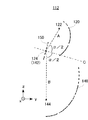
図2は、走査光学系112の配置を説明する概略図である。なお、簡略化のため二次元走査部130を省略した。
FIG. 2 is a schematic diagram for explaining the arrangement of the scanning optical system 112. For simplification, the two-dimensional scanning unit 130 is omitted.
第1反射鏡120は、第1焦点122および第2焦点124を有する。第1反射鏡120は、第1焦点122を通って入射したビーム光102を第2焦点124を通るように反射する。第1反射鏡120の一例は、これら第1焦点122および第2焦点124を長軸とした楕円を当該長軸周りに回転させた回転楕円体の一部を反射面とする楕円反射鏡である。
The first reflecting mirror 120 has a first focal point 122 and a second focal point 124. The first reflecting mirror 120 reflects the beam light 102 incident through the first focal point 122 so as to pass through the second focal point 124. An example of the first reflecting mirror 120 is an ellipsoidal reflecting mirror whose reflecting surface is a part of a spheroid obtained by rotating an ellipse having the first focal point 122 and the second focal point 124 as major axes around the major axis. .
第2反射鏡140は、第3焦点142および第4焦点144を有する。第2反射鏡140は、第3焦点142を通って入射したビーム光102を第4焦点144を通るように反射する。第2反射鏡140の一例は、これら第3焦点142および第4焦点144を長軸とした楕円を当該長軸周りに回転させた回転楕円体の一部を反射面とする楕円反射鏡である。
The second reflecting mirror 140 has a third focal point 142 and a fourth focal point 144. The second reflecting mirror 140 reflects the beam light 102 incident through the third focal point 142 so as to pass through the fourth focal point 144. An example of the second reflecting mirror 140 is an ellipsoidal reflecting mirror whose reflecting surface is a part of a spheroid obtained by rotating an ellipse having the major axis of the third focal point 142 and the fourth focal point 144 around the major axis. .
第2反射鏡140の第3焦点142の位置と第1反射鏡120の第2焦点124の位置とは、図2に示されるようにそれぞれの位置が完全に一致する場合を含み、さらに、設計上は同一であるが組み立て誤差等によって不可避にずれる場合なども含む。
The position of the third focal point 142 of the second reflecting mirror 140 and the position of the second focal point 124 of the first reflecting mirror 120 include the case where the respective positions completely coincide as shown in FIG. The above is the same, but includes the case where it inevitably deviates due to assembly errors.
平面反射鏡150は、第1反射鏡120の第2焦点124の位置に配置されている。図2に示す例において、平面反射鏡150は平面鏡であって、その反射面が第2焦点124を通るように配置され、ビーム光102の走査中に少なくとも固定されていればよく、走査前または走査後において光学的な調整のために動かされることも含む。上記の平面反射鏡150と第1焦点122との位置関係、さらに前述した第1反射鏡120の第2焦点124と第2反射鏡140の第3焦点142との位置関係は、理想的にはそれぞれ一致することが好適であるが、これらの位置関係には所定の範囲での一致が許容される。その範囲は、被検眼の虹彩位置にてビーム光の角度が2次元走査される際に、その走査ビーム光が眼の瞳孔内に入る範囲であり、眼底像の形成に支障がない限りの範囲となっている。
The planar reflecting mirror 150 is disposed at the position of the second focal point 124 of the first reflecting mirror 120. In the example shown in FIG. 2, the plane reflecting mirror 150 is a plane mirror, and the reflecting surface thereof is disposed so as to pass through the second focal point 124 and may be fixed at least during scanning of the beam light 102. It also includes being moved for optical adjustment after scanning. Ideally, the positional relationship between the plane reflecting mirror 150 and the first focal point 122, and the positional relationship between the second focal point 124 of the first reflecting mirror 120 and the third focal point 142 of the second reflecting mirror 140 are ideal. Although it is preferable to match each other, these positional relationships are allowed to match within a predetermined range. The range is a range in which, when the angle of the beam light is two-dimensionally scanned at the iris position of the eye to be examined, the scan beam light enters the eye pupil and does not interfere with the formation of the fundus image. It has become.
平面反射鏡150は、その法線Cの方向が、第1焦点122と第2焦点124とを結ぶ線分Aと、第3焦点142と第4焦点144とを結ぶ線分Bと、が成す角を二等分する方向となる向きに配される。これにより、平面反射鏡150は、第1反射鏡120で反射されたビーム光102を第2反射鏡140へ向けて反射する。なお線分Aと線分Bとが平行な場合は、それらの線分に直交する方向を法線Cとすればよい。
The direction of the normal line C of the plane reflecting mirror 150 includes a line segment A connecting the first focus 122 and the second focus 124 and a line segment B connecting the third focus 142 and the fourth focus 144. Arranged in a direction that bisects the angle. Thereby, the planar reflecting mirror 150 reflects the beam light 102 reflected by the first reflecting mirror 120 toward the second reflecting mirror 140. In addition, when the line segment A and the line segment B are parallel, the direction orthogonal to those line segments should just be made into the normal line C.
なお、平面反射鏡150の位置は図示した通り、第2焦点124(第3焦点142)に一致することにより最も小さくすることができる。しかしながら、平面反射鏡150の位置は、上述した向きが維持される限り、第2焦点124(第3142)から離れて配置されることも可能である。即ち、例えば図2に示した構成において、第1反射鏡から第2反射鏡に導かれる走査ビーム光が部分的に遮蔽されない限り、平面反射鏡150を任意の位置に平行移動した配置とすることが可能である。この場合には、平面反射鏡150の反射により形成される一方の反射鏡の虚の焦点に他方の反射鏡の焦点を一致させることはいうまでもない。
It should be noted that the position of the plane reflecting mirror 150 can be minimized by matching the second focal point 124 (third focal point 142) as shown. However, the position of the plane reflecting mirror 150 can be arranged away from the second focal point 124 (third 1422) as long as the above-described orientation is maintained. That is, for example, in the configuration shown in FIG. 2, the planar reflecting mirror 150 is translated to an arbitrary position unless the scanning beam light guided from the first reflecting mirror to the second reflecting mirror is partially blocked. Is possible. In this case, needless to say, the focal point of the other reflecting mirror coincides with the imaginary focal point of one reflecting mirror formed by the reflection of the planar reflecting mirror 150.
第1反射鏡120と第2反射鏡140とはその反射面と回転軸とが同じ向きの配置関係、すなわち、反射面に対して回転軸がほぼ-y側に配される。言い換えると、平面反射鏡150の存在により、第1反射鏡120と第2反射鏡140とは対向していない。なお、図2においても他の図面においても、第1反射鏡120、第2反射鏡140等を、長軸を含むzy平面にて切断した断面で示している。
The first reflecting mirror 120 and the second reflecting mirror 140 have an arrangement relationship in which the reflecting surface and the rotation axis are in the same direction, that is, the rotation axis is arranged on the substantially −y side with respect to the reflecting surface. In other words, due to the presence of the planar reflecting mirror 150, the first reflecting mirror 120 and the second reflecting mirror 140 are not opposed to each other. 2 and other drawings, the first reflecting mirror 120, the second reflecting mirror 140, and the like are shown as cross sections cut along a zy plane including the major axis.
第1反射鏡120の回転楕円体および第2反射鏡140の回転楕円体は、互いに等しい離心率を有する。互いに離心率が等しいことによりビーム光の角度走査の均一性が保たれ、ビーム光走査により得られる眼底像に歪が発生しなくなる。このことについては後述する。また、二次元走査部130で設定された走査範囲の光を反射できる程度の大きさがあれば、第1反射鏡120と第2反射鏡140との大きさは互いに等しくてもよく、異なっていてもよい。図2の例において、光源110に近い側の第1反射鏡120は、眼10に近い側の第2反射鏡140よりも小さい。これにより、装置全体を小型化することができる。
The spheroid of the first reflecting mirror 120 and the spheroid of the second reflecting mirror 140 have the same eccentricity. Since the eccentricity is equal to each other, the uniformity of the angle scanning of the light beam is maintained, and the fundus image obtained by the light beam scanning is not distorted. This will be described later. Further, the first reflecting mirror 120 and the second reflecting mirror 140 may be equal in size or different from each other as long as the light within a scanning range set by the two-dimensional scanning unit 130 can be reflected. May be. In the example of FIG. 2, the first reflecting mirror 120 on the side close to the light source 110 is smaller than the second reflecting mirror 140 on the side close to the eye 10. Thereby, the whole apparatus can be reduced in size.
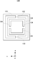
図3は、二次元走査部130の一例を示す概略図である。二次元走査部130は、本体131と、本体131に対してz軸のまわりに回動自在に連結部132により支持された枠体133と、枠体133に対してx軸まわりに回動自在に連結部134により支持され、ビーム光を反射する反射鏡135とを有する。二次元走査部130はいわゆるジンバル構造であって、例えばMEMSで構成され、制御部154により例えば静電駆動される。
FIG. 3 is a schematic diagram illustrating an example of the two-dimensional scanning unit 130. The two-dimensional scanning unit 130 is rotatable about the x axis with respect to the main body 131, the frame 133 supported by the connecting portion 132 so as to be rotatable about the z axis with respect to the main body 131, and the frame 133. And a reflecting mirror 135 that is supported by the connecting portion 134 and reflects the beam light. The two-dimensional scanning unit 130 has a so-called gimbal structure, and is configured by, for example, MEMS, and is electrostatically driven by the control unit 154, for example.
上記構成において、被検者の瞳孔12が第2反射鏡140の第4焦点144に対して予め定められた範囲内(第4焦点近傍に眼を置いた時に光ビームが入る範囲)で一致するように位置される。制御部154は、光源110からビーム光102を出射させるとともに、二次元走査部130の回動量を制御して反射鏡135をz軸回りおよびx軸回りに回動することにより、光源110からのビーム光102をz方向およびx方向に走査する。
In the above configuration, the pupil 12 of the subject coincides with the fourth focus 144 of the second reflecting mirror 140 within a predetermined range (a range in which the light beam enters when the eye is placed near the fourth focus). So positioned. The control unit 154 emits the beam light 102 from the light source 110 and controls the amount of rotation of the two-dimensional scanning unit 130 to rotate the reflecting mirror 135 about the z axis and the x axis, thereby causing the light source 110 to emit light. The beam light 102 is scanned in the z direction and the x direction.
二次元走査部130からのビーム光102が、第1反射鏡120、平面反射鏡150および第2反射鏡140の順に反射して、瞳孔12を通って網膜に到達する。網膜で反射したビーム光102は、上記光路を逆に辿って、ハーフミラー158に到達する。ハーフミラー158で反射されたビーム光102を検出器152で検出する。画像処理部156は制御部154により制御された二次元走査部130の回動量と、検出器152で検出された光量に基づいて、網膜の画像を二次元的に再構成して、モニター等に出力する。
The light beam 102 from the two-dimensional scanning unit 130 is reflected in the order of the first reflecting mirror 120, the planar reflecting mirror 150, and the second reflecting mirror 140, and reaches the retina through the pupil 12. The beam light 102 reflected from the retina traces the optical path in the reverse direction and reaches the half mirror 158. The light beam 102 reflected by the half mirror 158 is detected by the detector 152. The image processing unit 156 reconstructs the retina image two-dimensionally based on the amount of rotation of the two-dimensional scanning unit 130 controlled by the control unit 154 and the amount of light detected by the detector 152, and displays it on a monitor or the like. Output.
ここで、二次元走査部130により第1焦点122から出射するビーム光の角度変化と、第1反射鏡120で反射されて第2焦点124に入射するビーム光の角度変化との関係を考える。例えば、図1に示すように、二次元走査部130が、ある角度からx軸まわりに角度変化θ11だけビーム光を走査した場合と、さらにx軸まわりに同じ角度変化θ12(すなわちθ11=θ12)だけビーム光を走査した場合とを考える。
Here, the relationship between the change in the angle of the beam light emitted from the first focus 122 by the two-dimensional scanning unit 130 and the change in the angle of the beam light reflected by the first reflecting mirror 120 and incident on the second focus 124 will be considered. For example, as shown in FIG. 1, when the two-dimensional scanning unit 130 scans the beam light by an angle change θ 11 around the x axis from a certain angle, the same angle change θ 12 (that is, θ 11) around the x axis. Suppose that the beam light is scanned by = θ 12 ).
上記走査において第1反射鏡120の反射箇所の曲率の変化はそれぞれ異なるから、同じ角度変化θ11、θ12に対して、反射光が第2焦点124に向かうそれぞれの角度変化θ21、θ22は一般には異なる(すなわちθ21≠θ22)。当該角度はそれぞれ幾何学的に計算することができるが、図1の例においてはθ21<θ22となる。
Since the change in the curvature of the reflection portion of the first reflecting mirror 120 is different in the above scanning, the respective angle changes θ 21 and θ 22 toward the second focus 124 with respect to the same angle changes θ 11 and θ 12 . Are generally different (ie, θ 21 ≠ θ 22 ). Each of the angles can be calculated geometrically, but θ 21 <θ 22 in the example of FIG.
言い換えると、第1焦点122から出射するビーム光の角度変化と、角度変化に対応する、第1反射鏡120で反射されて第2焦点124に入射するビーム光の角度変化との比率は不均一である(θ11/θ12≠θ21/θ22)。
In other words, the ratio between the angle change of the beam light emitted from the first focus 122 and the angle change of the beam light reflected by the first reflecting mirror 120 and incident on the second focus 124 corresponding to the angle change is non-uniform. (Θ 11 / θ 12 ≠ θ 21 / θ 22 ).
平面鏡に対して入射角と反射角とは等しい。よって、角度変化θ21、θ22に対する平面反射鏡150での反射の角度変化をそれぞれθ31、θ32とすると、θ21=θ31、θ22=θ32となる。
The incident angle and the reflection angle are equal to the plane mirror. Therefore, if the angle changes of the reflection at the planar reflecting mirror 150 with respect to the angle changes θ 21 and θ 22 are θ 31 and θ 32 , respectively, θ 21 = θ 31 and θ 22 = θ 32 are obtained.
本実施形態において、第1反射鏡120の回転楕円体および第2反射鏡140の回転楕円体は、互いに等しい離心率を有し、かつ、平面反射鏡150は、その法線Cの方向が線分Aと線分Bとが成す角を二等分する方向となる向きに配されている。以上から、θ11/θ12=θ41/θ42となる。言い換えると、第1焦点122から出射するビーム光の角度変化と、角度変化に対応する、第4焦点144に入射するビーム光の角度変化との比率は均一となる。そして、明らかに、θ11=θ41、θ12=θ42となる。
In the present embodiment, the spheroid of the first reflecting mirror 120 and the spheroid of the second reflecting mirror 140 have the same eccentricity, and the plane reflecting mirror 150 has a normal C direction in the direction of the line. The angle formed by the segment A and the segment B is arranged in a direction that bisects the angle. From the above, θ 11 / θ 12 = θ 41 / θ 42 is obtained. In other words, the ratio between the change in the angle of the beam light emitted from the first focus 122 and the change in the angle of the beam light incident on the fourth focus 144 corresponding to the change in angle is uniform. Obviously, θ 11 = θ 41 and θ 12 = θ 42 .
上記構成によれば、二次元走査部130の回動量に対して、網膜の二次元画像を歪なく再構成することができる。また、二次元走査部130が二次元的な走査を担っており、第1反射鏡120と第2反射鏡140の共有焦点には走査中に機械的に可動する部分がないので、装置全体を簡略化および小型化することができる。
According to the above configuration, the two-dimensional image of the retina can be reconstructed without distortion with respect to the rotation amount of the two-dimensional scanning unit 130. Further, since the two-dimensional scanning unit 130 is responsible for two-dimensional scanning, and the shared focal point of the first reflecting mirror 120 and the second reflecting mirror 140 has no mechanically movable part during scanning, the entire apparatus is Simplification and miniaturization can be achieved.
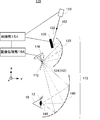
図4は、他の眼底像形成装置170の概略図を示す。眼底像形成装置170において、図1の眼底像形成装置100と同じ構成については同じ参照番号を付して説明を省略する。
FIG. 4 shows a schematic diagram of another fundus image forming apparatus 170. In the fundus image forming apparatus 170, the same components as those in the fundus image forming apparatus 100 in FIG.
眼底像形成装置170の走査光学系173は、図1の平面反射鏡150に代えてその位置およびその向きにハーフミラー172を有する。ハーフミラー172は第1反射鏡からのビーム光102を反射して第2反射鏡140に導くと共に、眼底からの反射光が第2反射鏡140を介して戻ってくるビーム光102の一部を透過する。
The scanning optical system 173 of the fundus image forming apparatus 170 has a half mirror 172 in its position and direction instead of the planar reflecting mirror 150 of FIG. The half mirror 172 reflects the beam light 102 from the first reflecting mirror and guides it to the second reflecting mirror 140, and also reflects a part of the beam light 102 from which the reflected light from the fundus returns through the second reflecting mirror 140. To Penetrate.
さらに眼底像形成装置100の検出器152に代えて、眼底像形成装置170には、ハーフミラー172における第2反射鏡140とは反対側に、光強度センサ174が配されている。光強度センサ174(例えばフォトダイオード)はハーフミラー172を透過したビーム光102の強度を検出する。
Furthermore, instead of the detector 152 of the fundus image forming apparatus 100, the fundus image forming apparatus 170 is provided with a light intensity sensor 174 on the opposite side of the half mirror 172 from the second reflecting mirror 140. The light intensity sensor 174 (eg, a photodiode) detects the intensity of the beam light 102 that has passed through the half mirror 172.
以上の構成により、二次元走査部130がビーム光102を二次元的に走査したことに対応して、光強度センサ174により検出された光強度に基づいて網膜の画像を生成することができる。なお、ハーフミラー172の位置については、前述した図1及び図2に示した平面反射鏡150と同様に、その配置向きが第1焦点122と第2焦点124とを結ぶ線分Aと、第3焦点142と第4焦点144とを結ぶ線分Bとが成す角を二等分する方向となる向きに配置される限り、焦点位置から外れて配置されることも可能である。
With the above configuration, a retina image can be generated based on the light intensity detected by the light intensity sensor 174 in response to the two-dimensional scanning unit 130 scanning the light beam 102 two-dimensionally. As for the position of the half mirror 172, the arrangement direction of the line segment A connecting the first focal point 122 and the second focal point 124 is similar to that of the planar reflecting mirror 150 shown in FIGS. As long as the angle formed by the line segment B connecting the three focal points 142 and the fourth focal point 144 is arranged in a direction that bisects the angle, the focal points can be arranged out of the focal position.
図5は、さらに他の眼底像形成装置180の概略図を示す。眼底像形成装置170において、図1の眼底像形成装置100と同じ構成については同じ参照番号を付して説明を省略する。
FIG. 5 shows a schematic view of still another fundus image forming apparatus 180. In the fundus image forming apparatus 170, the same components as those in the fundus image forming apparatus 100 in FIG.
眼底像形成装置180の走査光学系184において、第1反射鏡120と第2反射鏡140とは互いに対向して配されている。第1反射鏡120の第2焦点124と第2反射鏡140の第3焦点142とは、同一直線上に配置されている。換言すれば、第1反射鏡120としての楕円鏡と、第2反射鏡140としての楕円鏡との回転軸が一致している。この構成では、眼底像形成装置100とは異なり、第1反射鏡120と第2反射鏡140に至る光路中には何ら光学部材は配置されていない。
In the scanning optical system 184 of the fundus image forming apparatus 180, the first reflecting mirror 120 and the second reflecting mirror 140 are arranged to face each other. The second focal point 124 of the first reflecting mirror 120 and the third focal point 142 of the second reflecting mirror 140 are arranged on the same straight line. In other words, the rotation axes of the elliptical mirror as the first reflecting mirror 120 and the elliptical mirror as the second reflecting mirror 140 coincide. In this configuration, unlike the fundus image forming apparatus 100, no optical member is disposed in the optical path reaching the first reflecting mirror 120 and the second reflecting mirror 140.
以上の構成により、より少ない光学部材を用いて網膜の二次元画像を歪なく再構成することができる。
With the above configuration, a two-dimensional image of the retina can be reconstructed without distortion using fewer optical members.
上記実施形態はいずれも、第1反射鏡120および第2反射鏡140として回転楕円体の一部を反射面とする形状を用いている。これらの一方または両方を他の形状に代えてもよい。例えば、第1焦点122を焦点とする第1放物面回転体の一部と第2焦点124を焦点とする第2放物面回転体の一部とを組み合わせて、第1反射鏡120としてもよい。同様に、第2反射鏡140を二つの放物面回転体の一部の組み合わせにしてもよい。
In any of the above-described embodiments, the first reflecting mirror 120 and the second reflecting mirror 140 have a shape in which a part of a spheroid is a reflecting surface. One or both of these may be replaced with other shapes. For example, a part of the first paraboloid rotating body having the first focal point 122 as a focal point and a part of the second paraboloid rotating body having the second focal point 124 as a focal point are combined to form the first reflecting mirror 120. Also good. Similarly, the second reflecting mirror 140 may be a combination of a part of two paraboloid rotating bodies.
なお、上記の実施例の構成では、第1反射鏡120及び第2反射鏡140としてそれぞれ離心率の等しい楕円鏡を用いたが、2つの放物面鏡と2次元走査ミラーとを組み合わせて構成することも可能性である。ビーム光の2次元走査鏡を最初の放物面鏡の焦点上に配置し、次の放物面鏡の焦点位置に被検者の瞳孔12を位置付ける。放物面鏡1つの反射では、1つの楕円鏡と同様に、ビーム光の角度走査に不均一が生ずるが、2つの同一の放物面鏡を組み合わせることによって、ビーム光の角度走査の不均一性をキャンセルすることが可能である。この構成によっても、眼底像に歪曲収差の少ない鮮明な像を得ることが可能である。
In the configuration of the above embodiment, elliptical mirrors having the same eccentricity are used as the first reflecting mirror 120 and the second reflecting mirror 140, respectively. However, the configuration is configured by combining two parabolic mirrors and a two-dimensional scanning mirror. It is also possible to do. The two-dimensional scanning mirror of the beam light is placed on the focal point of the first parabolic mirror, and the pupil 12 of the subject is positioned at the focal position of the next parabolic mirror. In the reflection of one parabolic mirror, the angle scanning of the beam light is non-uniform, as in the case of one elliptical mirror, but by combining two identical parabolic mirrors, the angular scanning of the beam light is non-uniform. It is possible to cancel the sex. Also with this configuration, it is possible to obtain a clear image with little distortion in the fundus image.
以上、本発明を実施の形態を用いて説明したが、本発明の技術的範囲は上記実施の形態に記載の範囲には限定されない。上記実施の形態に、多様な変更または改良を加えることが可能であることが当業者に明らかである。その様な変更または改良を加えた形態も本発明の技術的範囲に含まれ得ることが、請求の範囲の記載から明らかである。
As mentioned above, although this invention was demonstrated using embodiment, the technical scope of this invention is not limited to the range as described in the said embodiment. It will be apparent to those skilled in the art that various modifications or improvements can be added to the above-described embodiment. It is apparent from the scope of the claims that the embodiments added with such changes or improvements can be included in the technical scope of the present invention.
請求の範囲、明細書、および図面中において示した装置、システム、プログラム、および方法における動作、手順、ステップ、および段階等の各処理の実行順序は、特段「より前に」、「先立って」等と明示しておらず、また、前の処理の出力を後の処理で用いるのでない限り、任意の順序で実現しうることに留意すべきである。請求の範囲、明細書、および図面中の動作フローに関して、便宜上「まず、」、「次に、」等を用いて説明したとしても、この順で実施することが必須であることを意味するものではない。
The execution order of each process such as operations, procedures, steps, and stages in the apparatus, system, program, and method shown in the claims, the description, and the drawings is particularly “before” or “prior”. It should be noted that they can be implemented in any order unless the output of the previous process is used in the subsequent process. Regarding the operation flow in the claims, the description, and the drawings, even if it is described using “first”, “next”, etc. for the sake of convenience, it means that it is essential to carry out in this order. is not.
10 眼、12 瞳孔、100 眼底像形成装置、102 ビーム光、110 光源、112 走査光学系、120 第1反射鏡、122 第1焦点、124 第2焦点、130 二次元走査部、131 本体、132 連結部、133 枠体、134 連結部、135 反射鏡、140 第2反射鏡、142 第3焦点、144 第4焦点、150 平面反射鏡、152 検出器、154 制御部、156 画像処理部、158 ハーフミラー、170 眼底像形成装置、172 ハーフミラー、173 走査光学系、174 光強度センサ、180 眼底像形成装置、184 走査光学系
10 eyes, 12 pupils, 100 fundus image forming apparatus, 102 beam light, 110 light source, 112 scanning optical system, 120 first reflecting mirror, 122 first focus, 124 second focus, 130 two-dimensional scanning unit, 131 body, 132 Connecting part, 133 frame, 134 connecting part, 135 reflecting mirror, 140 second reflecting mirror, 142 third focus, 144 fourth focus, 150 plane reflecting mirror, 152 detector, 154 control part, 156 image processing part, 158 Half mirror, 170 fundus image forming apparatus, 172 half mirror, 173 scanning optical system, 174 light intensity sensor, 180 fundus image forming apparatus, 184 scanning optical system
Claims (9)
- 被検者の網膜を走査する眼底像形成装置であって、
第1焦点を通って入射したビーム光を第2焦点を通るように反射する第1反射鏡と、
前記第1反射鏡の前記第1焦点の位置に配され、入射したビーム光を二次元方向に走査すべく反射する二次元走査部と、
第3焦点を通って入射したビーム光を第4焦点を通るように反射し、前記第3焦点の位置と前記第1反射鏡の前記第2焦点の位置とが一致するように配置される第2反射鏡とを備え、前記第2反射鏡の前記第4焦点の位置に前記被検者の瞳孔の位置が一致するように配置される眼底像形成装置。 A fundus image forming apparatus that scans the retina of a subject,
A first reflecting mirror that reflects the beam light incident through the first focal point so as to pass through the second focal point;
A two-dimensional scanning unit disposed at the position of the first focal point of the first reflecting mirror and reflecting the incident beam light to scan in a two-dimensional direction;
The beam light incident through the third focal point is reflected so as to pass through the fourth focal point, and the third focal point and the second focal point of the first reflecting mirror are arranged so as to coincide with each other. A fundus image forming apparatus that is arranged so that the position of the pupil of the subject coincides with the position of the fourth focus of the second reflecting mirror. - 前記二次元走査部は、
本体と、
前記本体に対して第1方向に回動自在に支持された枠体と、
前記枠体に対して前記第1方向に直交する第2方向に回動自在に支持され、ビーム光を反射する反射鏡と
を有する請求項1に記載の眼底像形成装置。 The two-dimensional scanning unit
The body,
A frame body rotatably supported in a first direction with respect to the main body;
The fundus image forming apparatus according to claim 1, further comprising a reflecting mirror that is rotatably supported in a second direction orthogonal to the first direction with respect to the frame body and reflects the beam light. - 前記第1反射鏡で反射されたビーム光を前記第2反射鏡へ向けて反射する平面反射鏡をさらに備える請求項1または2に記載の眼底像形成装置。 The fundus image forming apparatus according to claim 1, further comprising a planar reflecting mirror that reflects the beam light reflected by the first reflecting mirror toward the second reflecting mirror.
- 前記平面反射鏡は、前記第2反射鏡から戻ったビーム光の一部を透過し
前記平面反射鏡を透過したビーム光を検出する検出部をさらに備える請求項3に記載の眼底像形成装置。 The fundus image forming apparatus according to claim 3, wherein the planar reflecting mirror further includes a detection unit that detects part of the beam light that has returned from the second reflecting mirror and transmits the beam light that has passed through the planar reflecting mirror. - 前記平面反射鏡は、前記第1焦点と前記第2焦点とを結ぶ線分と、前記第3焦点と前記第4焦点とを結ぶ線分とがなす角を二等分する方向を法線とする平面鏡である請求項3または4に記載の眼底像形成装置。 The plane reflecting mirror has a normal direction that bisects an angle formed by a line segment connecting the first focus and the second focus and a line segment connecting the third focus and the fourth focus. The fundus image forming apparatus according to claim 3, wherein the fundus image forming apparatus is a plane mirror.
- 前記第1反射鏡と前記第2反射鏡は互いに対向して配された請求項1に記載の眼底像形成装置。 The fundus image forming apparatus according to claim 1, wherein the first reflecting mirror and the second reflecting mirror are arranged to face each other.
- 前記第1反射鏡および前記第2反射鏡は、回転楕円体の一部を反射面として有する請求項1から6のいずれか1項に記載の眼底像形成装置。 The fundus image forming apparatus according to any one of claims 1 to 6, wherein each of the first reflecting mirror and the second reflecting mirror has a part of a spheroid as a reflecting surface.
- 前記第1反射鏡および前記第2反射鏡は、互いに等しい離心率を有する回転楕円体の一部を反射面として有する請求項7に記載の眼底像形成装置。 The fundus image forming apparatus according to claim 7, wherein the first reflecting mirror and the second reflecting mirror have a part of a spheroid having an equal eccentricity as a reflecting surface.
- 前記第1反射鏡は、前記第2反射鏡よりも小さい請求項1から8のいずれか1項に記載の眼底像形成装置。 The fundus image forming apparatus according to any one of claims 1 to 8, wherein the first reflecting mirror is smaller than the second reflecting mirror.
Priority Applications (5)
| Application Number | Priority Date | Filing Date | Title |
|---|---|---|---|
| EP14909092.0A EP3238609B1 (en) | 2014-12-26 | 2014-12-26 | Fundus image forming device |
| PCT/JP2014/084630 WO2016103489A1 (en) | 2014-12-26 | 2014-12-26 | Fundus image forming device |
| CN201480084344.3A CN107106009B (en) | 2014-12-26 | 2014-12-26 | Fundus imaging device |
| JP2016565831A JP6380556B2 (en) | 2014-12-26 | 2014-12-26 | Fundus image forming apparatus |
| US15/630,324 US10398311B2 (en) | 2014-12-26 | 2017-06-22 | Fundus image forming device |
Applications Claiming Priority (1)
| Application Number | Priority Date | Filing Date | Title |
|---|---|---|---|
| PCT/JP2014/084630 WO2016103489A1 (en) | 2014-12-26 | 2014-12-26 | Fundus image forming device |
Related Child Applications (1)
| Application Number | Title | Priority Date | Filing Date |
|---|---|---|---|
| US15/630,324 Continuation US10398311B2 (en) | 2014-12-26 | 2017-06-22 | Fundus image forming device |
Publications (1)
| Publication Number | Publication Date |
|---|---|
| WO2016103489A1 true WO2016103489A1 (en) | 2016-06-30 |
Family
ID=56149572
Family Applications (1)
| Application Number | Title | Priority Date | Filing Date |
|---|---|---|---|
| PCT/JP2014/084630 WO2016103489A1 (en) | 2014-12-26 | 2014-12-26 | Fundus image forming device |
Country Status (5)
| Country | Link |
|---|---|
| US (1) | US10398311B2 (en) |
| EP (1) | EP3238609B1 (en) |
| JP (1) | JP6380556B2 (en) |
| CN (1) | CN107106009B (en) |
| WO (1) | WO2016103489A1 (en) |
Cited By (5)
| Publication number | Priority date | Publication date | Assignee | Title |
|---|---|---|---|---|
| CN108567409A (en) * | 2017-03-13 | 2018-09-25 | 温州雷蒙光电科技有限公司 | A kind of off axis reflector mirror retina imaging system |
| WO2019065245A1 (en) * | 2017-09-29 | 2019-04-04 | 株式会社Qdレーザ | Image projection device |
| JP2019174663A (en) * | 2018-03-28 | 2019-10-10 | 株式会社Qdレーザ | Image projection device |
| JP2020103422A (en) * | 2018-12-26 | 2020-07-09 | 株式会社トプコン | Ophthalmologic apparatus and control method thereof |
| WO2021038847A1 (en) | 2019-08-30 | 2021-03-04 | 株式会社ニコン | Image processing method, image processing device, and program |
Families Citing this family (1)
| Publication number | Priority date | Publication date | Assignee | Title |
|---|---|---|---|---|
| CN113842108A (en) * | 2021-09-15 | 2021-12-28 | 北京大学 | Imaging system for the fundus retina |
Citations (3)
| Publication number | Priority date | Publication date | Assignee | Title |
|---|---|---|---|---|
| JP2010508932A (en) * | 2006-11-09 | 2010-03-25 | オプトス ピーエルシー | Improvements on retinal scanning |
| JP2013532039A (en) * | 2010-07-01 | 2013-08-15 | オプトス、ピーエルシー | Improvement in ophthalmology or ophthalmology |
| JP2014502552A (en) * | 2011-01-13 | 2014-02-03 | オプトス ピーエルシー | Improvement in or ophthalmology |
Family Cites Families (9)
| Publication number | Priority date | Publication date | Assignee | Title |
|---|---|---|---|---|
| GB9323065D0 (en) | 1993-11-09 | 1994-01-05 | Besca Ltd | A wide field retinal scanning ophthalmoscope |
| JP4680373B2 (en) * | 2000-11-16 | 2011-05-11 | オリンパス株式会社 | Galvano mirror |
| GB2440163A (en) * | 2006-07-15 | 2008-01-23 | Optos Plc | Scanning ophthalmoscope with reduced shear distortion |
| GB0907557D0 (en) | 2009-05-01 | 2009-06-10 | Optos Plc | Improvements in or relating to scanning ophthalmoscopes |
| GB0913911D0 (en) | 2009-08-10 | 2009-09-16 | Optos Plc | Improvements in or relating to laser scanning systems |
| GB201007046D0 (en) | 2010-04-28 | 2010-06-09 | Optos Plc | Improvements in or relating to scanning ophthalmoscopes |
| US8284478B2 (en) | 2010-06-30 | 2012-10-09 | Femtolasers Produktions Gmbh | Device for increasing the spectral bandwidth of optical pulses as well as an arrangement and a method for reducing the duration of optical pulses with the use of such a device |
| GB201307936D0 (en) | 2013-05-02 | 2013-06-12 | Optos Plc | Improvements in and relating to ophthalmoscopes |
| JP2016067551A (en) * | 2014-09-29 | 2016-05-09 | キヤノン株式会社 | Ophthalmologic apparatus |
-
2014
- 2014-12-26 EP EP14909092.0A patent/EP3238609B1/en active Active
- 2014-12-26 CN CN201480084344.3A patent/CN107106009B/en active Active
- 2014-12-26 JP JP2016565831A patent/JP6380556B2/en active Active
- 2014-12-26 WO PCT/JP2014/084630 patent/WO2016103489A1/en active Application Filing
-
2017
- 2017-06-22 US US15/630,324 patent/US10398311B2/en active Active
Patent Citations (3)
| Publication number | Priority date | Publication date | Assignee | Title |
|---|---|---|---|---|
| JP2010508932A (en) * | 2006-11-09 | 2010-03-25 | オプトス ピーエルシー | Improvements on retinal scanning |
| JP2013532039A (en) * | 2010-07-01 | 2013-08-15 | オプトス、ピーエルシー | Improvement in ophthalmology or ophthalmology |
| JP2014502552A (en) * | 2011-01-13 | 2014-02-03 | オプトス ピーエルシー | Improvement in or ophthalmology |
Non-Patent Citations (1)
| Title |
|---|
| See also references of EP3238609A4 * |
Cited By (11)
| Publication number | Priority date | Publication date | Assignee | Title |
|---|---|---|---|---|
| CN108567409A (en) * | 2017-03-13 | 2018-09-25 | 温州雷蒙光电科技有限公司 | A kind of off axis reflector mirror retina imaging system |
| CN108567409B (en) * | 2017-03-13 | 2023-11-03 | 温州高视雷蒙光电科技有限公司 | Off-axis reflector retina imaging system |
| WO2019065245A1 (en) * | 2017-09-29 | 2019-04-04 | 株式会社Qdレーザ | Image projection device |
| JPWO2019065245A1 (en) * | 2017-09-29 | 2019-11-14 | 株式会社Qdレーザ | Image projection device |
| US11428926B2 (en) | 2017-09-29 | 2022-08-30 | Qd Laser, Inc. | Image projection device |
| JP2019174663A (en) * | 2018-03-28 | 2019-10-10 | 株式会社Qdレーザ | Image projection device |
| JP7050292B2 (en) | 2018-03-28 | 2022-04-08 | 株式会社Qdレーザ | Image projection device |
| JP2020103422A (en) * | 2018-12-26 | 2020-07-09 | 株式会社トプコン | Ophthalmologic apparatus and control method thereof |
| US11490802B2 (en) | 2018-12-26 | 2022-11-08 | Topcon Corporation | Ophthalmologic apparatus and method for controlling the same |
| JP7231404B2 (en) | 2018-12-26 | 2023-03-01 | 株式会社トプコン | Ophthalmic device and its control method |
| WO2021038847A1 (en) | 2019-08-30 | 2021-03-04 | 株式会社ニコン | Image processing method, image processing device, and program |
Also Published As
| Publication number | Publication date |
|---|---|
| EP3238609A4 (en) | 2018-08-08 |
| EP3238609B1 (en) | 2021-10-20 |
| JPWO2016103489A1 (en) | 2017-09-07 |
| US20170347881A1 (en) | 2017-12-07 |
| CN107106009A (en) | 2017-08-29 |
| JP6380556B2 (en) | 2018-08-29 |
| CN107106009B (en) | 2019-09-13 |
| EP3238609A1 (en) | 2017-11-01 |
| US10398311B2 (en) | 2019-09-03 |
Similar Documents
| Publication | Publication Date | Title |
|---|---|---|
| JP6380556B2 (en) | Fundus image forming apparatus | |
| KR102165689B1 (en) | Improvements in or relating to Scanning Laser Ophthalmoscopes | |
| US20120133888A1 (en) | scanning ophthalmoscopes | |
| JP6019014B2 (en) | Improvement of scanning ophthalmoscope or improvement on scanning ophthalmoscope | |
| KR101629911B1 (en) | Imaging technique for optical coherence tomography | |
| US9649025B2 (en) | Scanning optical system with multiple optical sources | |
| EP3150109B1 (en) | Fundus imaging device | |
| JP6701659B2 (en) | Fundus imaging device | |
| JP6776777B2 (en) | Fundus photography device | |
| US10362938B2 (en) | Fundus image forming device | |
| JP6525099B2 (en) | Fundus image forming device | |
| JP6711392B2 (en) | Fundus image forming device |
Legal Events
| Date | Code | Title | Description |
|---|---|---|---|
| 121 | Ep: the epo has been informed by wipo that ep was designated in this application |
Ref document number: 14909092 Country of ref document: EP Kind code of ref document: A1 |
|
| ENP | Entry into the national phase |
Ref document number: 2016565831 Country of ref document: JP Kind code of ref document: A |
|
| NENP | Non-entry into the national phase |
Ref country code: DE |
|
| REEP | Request for entry into the european phase |
Ref document number: 2014909092 Country of ref document: EP |