WO2016103454A1 - 作業機械ライン - Google Patents
作業機械ライン Download PDFInfo
- Publication number
- WO2016103454A1 WO2016103454A1 PCT/JP2014/084535 JP2014084535W WO2016103454A1 WO 2016103454 A1 WO2016103454 A1 WO 2016103454A1 JP 2014084535 W JP2014084535 W JP 2014084535W WO 2016103454 A1 WO2016103454 A1 WO 2016103454A1
- Authority
- WO
- WIPO (PCT)
- Prior art keywords
- signal tower
- work
- work machine
- machine line
- hole
- Prior art date
- Legal status (The legal status is an assumption and is not a legal conclusion. Google has not performed a legal analysis and makes no representation as to the accuracy of the status listed.)
- Ceased
Links
Images





Classifications
-
- B—PERFORMING OPERATIONS; TRANSPORTING
- B23—MACHINE TOOLS; METAL-WORKING NOT OTHERWISE PROVIDED FOR
- B23Q—DETAILS, COMPONENTS, OR ACCESSORIES FOR MACHINE TOOLS, e.g. ARRANGEMENTS FOR COPYING OR CONTROLLING; MACHINE TOOLS IN GENERAL CHARACTERISED BY THE CONSTRUCTION OF PARTICULAR DETAILS OR COMPONENTS; COMBINATIONS OR ASSOCIATIONS OF METAL-WORKING MACHINES, NOT DIRECTED TO A PARTICULAR RESULT
- B23Q41/00—Combinations or associations of metal-working machines not directed to a particular result according to classes B21, B23, or B24
- B23Q41/08—Features relating to maintenance of efficient operation
-
- G—PHYSICS
- G08—SIGNALLING
- G08B—SIGNALLING SYSTEMS, e.g. PERSONAL CALLING SYSTEMS; ORDER TELEGRAPHS; ALARM SYSTEMS
- G08B5/00—Visible signalling systems, e.g. visible personal calling systems or remote indication of seats occupied
- G08B5/22—Visible signalling systems, e.g. visible personal calling systems or remote indication of seats occupied using electric transmission; using electromagnetic transmission
- G08B5/36—Visible signalling systems, e.g. visible personal calling systems or remote indication of seats occupied using electric transmission; using electromagnetic transmission using visible light sources
-
- B—PERFORMING OPERATIONS; TRANSPORTING
- B23—MACHINE TOOLS; METAL-WORKING NOT OTHERWISE PROVIDED FOR
- B23Q—DETAILS, COMPONENTS, OR ACCESSORIES FOR MACHINE TOOLS, e.g. ARRANGEMENTS FOR COPYING OR CONTROLLING; MACHINE TOOLS IN GENERAL CHARACTERISED BY THE CONSTRUCTION OF PARTICULAR DETAILS OR COMPONENTS; COMBINATIONS OR ASSOCIATIONS OF METAL-WORKING MACHINES, NOT DIRECTED TO A PARTICULAR RESULT
- B23Q11/00—Accessories fitted to machine tools for keeping tools or parts of the machine in good working condition or for cooling work; Safety devices specially combined with or arranged in, or specially adapted for use in connection with, machine tools
Definitions
- the present invention relates to a work machine line that includes a plurality of work machines, and each work machine has a signal tower attached thereto.
- Patent Document 2 discloses a work machine line in which a plurality of mounting machines are arranged, and a plurality of similar mounting machines are each provided with a signal tower.
- the signal tower can be turned on or blinked for each of three colors of “red”, “green”, and “yellow”, and the display is controlled in accordance with a predetermined operation status.
- the operator visually confirms the signal tower, and if it is lit green, it is normal operation, if it is lit red, a failure or malfunction has occurred, and if it is blinking yellow, the part
- the operating status of the work machine can be grasped by each preset display such as the time for replacement approaching.
- the worker performs a predetermined work as necessary according to the display of the signal tower. For example, if the signal tower of a certain work machine blinks in “yellow”, it can be seen that the work machine is approaching component replacement. Therefore, the operator prepares necessary replacement parts and heads to the corresponding work machine to perform replacement work. However, the operator does not always check the signal tower in front of the work machine, and often sees the warning display of the signal tower from a remote location. At this time, for example, as shown in FIG. 12, if the mounting state of the plurality of signal towers 10 is constant, it is easy to mistake from a remote position, and the work machine of the signal tower 10 displaying the warning is displayed. You may make a mistake. In addition, wrong replacement parts are prepared, and work is wasted.
- an object of the present invention is to provide a work machine line in which a signal tower can be easily confirmed in order to solve such a problem.
- a plurality of work machines including a work unit that performs a predetermined work on a work object are arranged, and the work object is conveyed to the work part of the work machine.
- Each work machine is provided with a signal tower that displays a moving state, and the signal tower is a bar-shaped unit in which a display part is formed on the upper side and a mounting part is provided on the lower side.
- the mounting portion and the mounted portion on the work machine side constitute a fixing structure in which the signal tower can be fixed in a plurality of postures.
- a warning display is performed. It is easier for the operator to confirm the signal tower that has been used.
- FIG. 1 is a perspective view showing a work machine line of the present embodiment.
- eight machine tools 5 are mounted on a base 2 as a foundation.
- the eight machine tools 5 are all NC lathes of the same type, and have the same outer shape and dimensions.
- the work machine line 1 is provided with a workpiece transfer device (not shown) that delivers workpieces to each machine tool 5.
- the machine tool 5 is entirely covered with an exterior cover 3, and a front cover 4 is provided at a front portion on the front side of the drawing, and the exterior cover 3 and the front cover 4 are integrated.
- a processing module 6 (see FIG. 2) that performs processing such as cutting on the workpiece is mounted inside the exterior cover 3, and a closed processing chamber is configured for each machine tool 5.
- the front cover 4 constitutes one conveyance space in the width direction of the work machine line 1, and a conveyance device for conveying the workpiece to the machining chamber of each machine tool 5 is installed therein. .
- the “work machine line” has a plurality of work machines such as machine tools, and a work object such as a work is delivered by a transfer device, and each work machine performs a predetermined work on the work object. Means a group of work machines on which is executed.
- a work machine line for processing a workpiece by the machine tool 5 will be described and described.
- a work machine line configured by a mounting machine as described in Patent Document 2 may be used.
- a plurality of mounting machines are installed side by side, and a substrate as a work object is transferred by a transfer device, and predetermined electronic components are mounted on the board in each mounting machine.
- FIG. 2 is a perspective view showing the machining module 6 that is the internal structure of the machine tool 5, and shows a state in which the machining module 6 is placed on the carriage 9 and pulled out to the rear of the base 2.
- a processing module 6 is mounted on the base 2 and is covered with an exterior cover 3.
- two machining modules 6 can be mounted on one base 2, and rails are formed on the base 2 according to the width of the machining module 6.
- Two 201 are provided. Therefore, the working machine line 1 having eight machine tools 5 has four bases 2 arranged close to each other in the width direction.
- the machining module 6 is a turret lathe equipped with a tool table on which a rotary tool such as an end mill or a drill or a cutting tool such as a cutting tool is mounted. Therefore, the machining module 6 includes a headstock 61 having a chuck, a turret device 62 having a tool table, a Z-axis drive device 63 and an X-axis drive device 64 that move the turret device 62 along the Z-axis and the X-axis, And a control device 65 for controlling each drive device.
- the driving devices 63 and 64, the control device 65, and the like are mounted on a movable bed 66 having wheels, and the movable bed 66 can run on the rail 201 of the base 2. Installed at.
- the processing module 6 can be exchanged by moving it to a carriage 9 disposed behind the base 2, and when the machining module 6 is pulled forward, the tool can be exchanged. . Therefore, even if the machine tools 5 are close to each other as shown in FIG. 1, the work machine line 1 can perform work such as maintenance without being influenced by the adjacent machine tools 5.
- the processing module 6 can be pulled out integrally with the exterior cover 3.
- a signal tower 10 is attached to the upper front portion of the exterior cover 3 so that the operating state of the machine tool 5 can be confirmed by an operator.
- the signal tower 10 has a display unit 12 that emits light in three colors of “red”, “green”, and “yellow”. Etc. are also possible.
- the signal tower 10 is controlled in accordance with detection signals and programs from the sensors provided in the headstock 12 and the driving devices 63 and 64 by the control device 65 so that the lighting display and blinking display of each color are supported. The emitted light is executed.
- the display of the predetermined operating status is, for example, as follows.
- the machine tool 5 is subjected to predetermined machining by the control device 65 in accordance with a machining program stored in advance. For example, it is possible to check the number of times the workpiece is cut by the cutting tool, and the tool life, that is, the time for replacement of the tool by the operator is counted. For this reason, the signal tower 10 is normally “green” lighting display, but is switched to “yellow” lighting display when the number of times set as the replacement time is reached. At that time, “yellow” is blinked in the signal tower 10 at a time point that is a predetermined number of times less than the number of replacements, and the operator is notified that the time for tool replacement is approaching. In addition, when a detection signal indicating a malfunction is received by the sensor of the driving unit, “red” indicating a failure is lit on the signal tower 10.
- the operator can make appropriate preparations for the next operation by checking the warning display of the signal tower 10 and can minimize time loss due to tool change.
- the operation stop time of the work machine line 1 can be minimized.
- such an effect requires an operator to immediately confirm the display change of the signal tower 10 and to understand which machine tool 5 is in what operating state. Therefore, the signal tower 10 is required to be easy for the operator to see.
- the signal tower 10 is required to be easy for the operator to see.
- a plurality of machine tools 5 are arranged like the work machine line 1, it is required that the corresponding machine tool 5 can be identified.
- FIG. 12 is a perspective view showing a conventional signal tower mounting state in the work machine line 1.
- the work machine line 1 has the same appearance design of the eight machine tools 5 and has the same width and height. Therefore, although it is constituted by a plurality of machine tools 5, an overall impression is given.
- the machine tool 5 is designed to have a small width dimension, and as shown in the figure, eight machine tools 5 are arranged very close to each other in the width direction. Therefore, the work machine line 1 is configured to be very compact as a whole.
- the work machine line 1 that is easy for the operator to check even if the same signal tower is arranged close to each other is provided at low cost.
- the plurality of signal towers 10 of the work machine line 1 are arranged at a short distance and continuously in the same posture. For this reason, it becomes difficult to see the signal tower 10 emitting a warning display depending on the viewing position, or the positional relationship becomes difficult to understand.
- the posture of the signal tower 10 can be changed.
- the signal tower 10 in the vertically standing posture not only the signal tower 10 in the vertically standing posture but also the signal tower 10 in the forward leaning posture is provided.
- the signal tower 10 in the standing posture and the signal tower 10 in the forward leaning posture are alternately arranged.
- the distance between the signal towers 10 having the same posture is increased.
- the positional relationship of the signal towers 10 to be confirmed is accentuated by the signal towers 10 having different postures. Therefore, the position of the signal tower 10 emitting the warning display and the corresponding machine tool 5 can be easily grasped by the operator.
- FIG. 3 to FIG. 5 are diagrams showing a fixing structure of the signal tower 10.
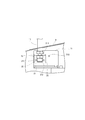
- FIG. 3 shows an attached state in which the signal tower 10 stands up
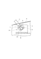
- FIG. 4 shows an attached state in which the signal tower 10 leans forward
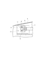
- FIG. 5 is a view showing an attached state in which the signal tower 10 is housed in the exterior cover 3 in a lying posture.
- the signal tower 10 is attached so as to protrude from a notch formed on the right side of the front end of the roof of the exterior cover 3. Therefore, the fixing structure shown in FIGS. 3 to 5 is formed on the front upper side surface portion in the exterior cover 3.
- the signal tower 10 is provided with a display portion 12 (see FIG. 1) above a cylindrical pole 11 and an attachment portion 13 below.
- the mounting portion 13 is a mounting bracket 21 fixed to the lower end portion of the pole 11 via a nut.
- a fixing plate 31 is provided on the exterior cover 3 side as a mounting portion for fixing the mounting bracket 21 (that is, the signal tower 10).
- the fixing plate 31 has a plurality of screw holes in which the bolts 22 can be tightened. Specifically, as shown in FIGS. 3 and 4, four screw holes 311, 312, 313, and 314 are formed.
- These screw holes 311, 312, 313, and 314 are formed for attaching the signal tower 10 in different postures.
- the screw holes 311 and 312 are used in the standing posture shown in FIG. 3, the screw holes 312 and 313 are used in the forward tilting posture shown in FIG. 4, and the screw holes 312 and 314 are in the lying posture shown in FIG. Used when.
- the posture of the signal tower 10 can be changed to three patterns, but the screw hole 312 is a common screw hole used for attachment in any posture.
- the fixing structure of the signal tower 10 is common to all the machine tools 5 in the work machine line 1.
- Patent Document 1 discloses a pole-type signal tower that can be folded during loading and unloading. Certainly the signal tower can be stored without getting in the way, and handling is also convenient. However, the structure is complex and can only be switched between a standing posture and a folded lying posture. In this respect, in the present embodiment, not only the signal tower 10 can be stowed and stored, but also after being installed as the work machine line 1, as shown in FIG. The signal tower 10 can be reattached, and the operation is extremely simple.
- the change in posture when a plurality of signal towers 10 are arranged does not necessarily have to be alternated as shown in FIG. This is because the change in posture of the signal tower 10 is intended to enable the operator to confirm the warning display accurately and reliably. Therefore, it may be determined in consideration of the installation status of the work machine line 1 in the factory, the standing position of the worker, the work procedure, and the like. For example, when a plurality of work machine lines 1 are installed side by side, the work machine line 1 close to the worker's position is the conventional type shown in FIG. 12, and the distant work machine line 1 is the type shown in FIG. To do.
- the posture of the signal tower 10 can be set according to various situations.
- the signal tower 10 can be attached only by changing the direction of the mounting bracket 21 with respect to the fixing plate 31 and handling only the two bolts 22.
- the fixing plate 31 has a very simplified structure in which one screw hole 313 is added to the inclined posture and one screw hole 314 is added to the lying posture. .
- position change of the signal tower 10 can be acquired at a very low cost only by adding a little process to the existing thing without requiring a new component.
- the fixing structure makes it possible to attach the signal tower 10 in a forward inclined posture of a predetermined angle in addition to the standing posture and the lying posture.
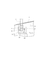
- the first modification shown in FIGS. 6 to 8 is a fixed structure that enables angle adjustment within a certain range.
- This fixing structure is configured so that the mounting bracket 23 of the mounting portion 15 can be mounted in a swingable state.
- the mounting bracket 23 has a fulcrum through hole 231 through which a bolt 22 serving as a fulcrum is passed, and a curved long hole swing through hole 232 on the other bolt 22 side. Is formed.
- FIG. 6 shows a fulcrum through hole 231 through which a bolt 22 serving as a fulcrum is passed, and a curved long hole swing through hole 232 on the other bolt 22 side. Is formed.
- the fixing plate 33 includes a screw hole 331 for tightening the bolt 22 through the fulcrum through hole 231, a screw hole 332 for tightening the bolt 22 through the rocking through hole 232, and a lying posture.
- a screw hole 333 is formed.
- the mounting bracket 23 can swing and slide with the bolt 22 on the fulcrum through-hole 231 side as a fulcrum by loosening the two bolts 22. Then, the other bolt 22 relatively moves in the swinging through hole 231, the two bolts 22 are tightened at an arbitrary position, and the mounting bracket 23 that is inclined as shown in FIG. Fixed to. According to this fixing structure, adjustment at an arbitrary angle is possible within a certain range without removing the mounting bracket 23. Therefore, the signal tower 10 can be in a forward inclined posture at a plurality of angles. On the other hand, when storing, the mounting bracket 23 is removed, the signal tower 10 is turned sideways as shown in FIG. 8, and the mounting bracket 23 is screwed and fixed using the screw holes 331 and 333.
- FIGS. 9 to 11 are views showing a second modification of the fixing structure.
- This second modification is a fixed structure that allows height adjustment within a certain range.
- This fixing structure is configured so that the mounting bracket 25 of the mounting portion 17 can be mounted in a state where it can be moved up and down.
- the mounting bracket 25 is formed with elongate through holes 251 and 252 that are elongated in the vertical direction at the left and right positions sandwiching the pole 11.
- the fixing plate 35 is formed with screw holes 351, 352 for tightening the two bolts 22 passed through the lifting through holes 251, 252 and screw holes 353 for the lying posture. .
- the mounting bracket 25 can be lifted and lowered by loosening the two bolts 22. Then, the bolt 22 relatively moves in the lifting through holes 251 and 252, the two bolts 22 are tightened at an arbitrary position, and the mounting bracket 25 is attached to the fixing plate 35 at a height as shown in FIG. 10. Fixed. According to this fixing structure, adjustment at an arbitrary height is possible within a certain range without removing the mounting bracket 25. Therefore, the signal tower 10 can be changed to a plurality of height postures. On the other hand, when storing, the mounting bracket 25 is removed, the signal tower 10 is turned sideways as shown in FIG. 11, and the mounting bracket 25 is screwed and fixed using the screw holes 352 and 353.
- the first modification 1 has only an angular posture change and the second modification 2 has only a height posture change, both of which are within the range of the swinging through hole 232 or the lifting through holes 251 and 252.
- the posture can be continuously changed with and can be fixed at an arbitrary angle or height.
- the eight machine tools 5 shown in FIG. 1 may be divided into two groups of four, and the angle and height of each group of signal towers 10 may be changed continuously in the same manner.
- the signal tower 10 With respect to the work machine line 1 that is configured integrally, the signal tower 10 can be identified in two groups, and the signal tower 10 that is displayed with an alarm can be confirmed accurately.
- the posture is not limited to this, and the posture can be changed in various patterns.
- the signal tower 10 can be changed in posture by simply swinging or sliding up and down without removing the mounting brackets 23 and 25 except for the lying posture, and by loosening the two bolts 22 and retightening. It's okay.
- the fixing plates 33 and 35 have a very simplified configuration in which three screw holes 331, 332 and 333 or screw holes 351, 352 and 353 are formed. Furthermore, the effect by the change in the attitude of the signal tower 10 can be obtained at a very low cost by adding the swinging through hole 232 and the lifting through holes 251 and 252 to the existing one without requiring any new parts. .
Landscapes
- Physics & Mathematics (AREA)
- Electromagnetism (AREA)
- General Physics & Mathematics (AREA)
- Engineering & Computer Science (AREA)
- Mechanical Engineering (AREA)
- Multi-Process Working Machines And Systems (AREA)
- Audible And Visible Signals (AREA)
- Component Parts Of Construction Machinery (AREA)
Abstract
シグナルタワー(10)を確認しやすい作業機械ライン(1)を提供することを目的としたものであり、作業対象物に対して所定の作業を行う作業部(6)を備えた作業機械(5)が複数並べられ、作業機械(5)の作業部(6)に対して作業対象物の搬送を行う搬送装置を有し、各作業機械(5)には可動状況を表示するシグナルタワー(10)が設けられたものであり、そのシグナルタワー(10)は、上方に表示部(12)が形成され下方に取付部(13)が設けられた棒形状のものであり、取付部(13)および作業機械(5)側の被取付部(31)は、シグナルタワー(10)が複数の姿勢で固定可能な固定構造を構成するものである。
Description
本発明は、複数の作業機械によって構成され、各々の作業機械にシグナルタワーが取り付けられた作業機械ラインに関する。
複数の工作機械や実装機などの作業機械が並んだ作業機械ラインにおいて加工や実装などが行われる場合、作業者には各々の作業機械の稼動状況を把握することが求められている。そのため各々の作業機械には、稼働状況を表示するためのシグナルタワーが設けられている。例えば、下記特許文献2には複数の実装機が並べられた作業機械ラインが開示されており、複数ある同種の実装機には各々シグナルタワーが設けられている。シグナルタワーは、例えば「赤」「緑」「黄」の3色それぞれにおいて点灯表示や点滅表示が可能であり、所定の稼働状況に対応して表示が制御される。作業者は、シグナルタワーを視認することにより、「緑」の点灯であれば通常運転であり、「赤」の点灯であれば故障や不具合が発生し、「黄」の点滅であれば部品の交換時期が近づいているなど、予め設定された各表示により作業機械の稼働状況を把握することができる。
従って、作業者は、シグナルタワーの表示に従い、必要に応じて所定の作業を行うこととなる。例えば、ある作業機械のシグナルタワーが「黄」に点滅していれば、その作業機械は部品交換が近づいていることが分かる。そのため作業者は、必要な交換部品を用意して該当する作業機械へと向かい、交換作業を行うことになる。ただし、作業者は常に作業機械の前でシグナルタワーを確認しているわけではなく、離れた位置からシグナルタワーの警告表示などを見ることも多々ある。このとき、例えば図12に示すように、複数あるシグナルタワー10の取り付け状態が一定であると、離れた位置からは見間違いが起こりやすくなり、警告を表示しているシグナルタワー10の作業機械を間違えてしまうことがある。そして、間違った交換部品を用意してしまうことになり、作業に無駄を生じさせてしまう。
そこで、本発明は、かかる課題を解決すべく、シグナルタワーを確認しやすい作業機械ラインを提供することを目的とする。
本発明の一態様における作業機械ラインは、作業対象物に対して所定の作業を行う作業部を備えた作業機械が複数並べられ、前記作業機械の作業部に対して作業対象物の搬送を行う搬送装置を有し、前記各作業機械には可動状況を表示するシグナルタワーが設けられたものであり、前記シグナルタワーは、上方に表示部が形成され下方に取付部が設けられた棒形状のものであり、前記取付部および前記作業機械側の被取付部は、前記シグナルタワーが複数の姿勢で固定可能な固定構造を構成するものである。
本発明によれば、作業機械が複数並べられた作業機械ラインの複数のシグナルタワーが複数の姿勢で固定されるため、同じ複数のシグナルタワーが近い位置で配置されていたとしても、警告表示の行われたシグナルタワーが作業者にとって確認しやすくなる。
次に、本発明に係る作業機械ラインの一実施形態について、図面を参照しながら以下に説明する。図1は、本実施形態の作業機械ラインを示した斜視図である。作業機械ライン1は、基礎となるベース2の上に8台の工作機械5が搭載されている。8台の工作機械5はいずれも同じ型のNC旋盤であり、外形形状や寸法が揃えられている。そして作業機械ライン1には、各々の工作機械5に対してワークの受渡しを行う不図示のワーク搬送装置が設けられている。
工作機械5は、全体が外装カバー3によって覆われており、図面手前側である前部には前カバー4があり、外装カバー3と前カバー4とが一体になっている。外装カバー3の内部には、ワークに対して切削などの加工を行う加工モジュール6(図2参照)が搭載され、工作機械5ごとに閉じた加工室が構成されている。一方、前カバー4は、作業機械ライン1の幅方向に一つの搬送空間を構成し、その内部には各工作機械5の加工室に対してワークを搬送するための搬送装置が設置されている。
ここで「作業機械ライン」とは、工作機械などの複数の作業機械を有し、搬送装置によってワークなどの作業対象物の受け渡しが行われ、各作業機械において作業対象物に対して所定の作業が実行される作業機械群をいう。本実施形態では工作機械5によってワークを加工する作業機械ラインを示して説明するが、前記特許文献2に記載されているような実装機によって構成される作業機械ラインであってもよい。実装機による作業機械ラインであれば、複数の実装機が横並びに設置され、その中を作業対象物である基板が搬送装置によって搬送され、各実装機において基板に各々所定の電子部品が装着される。
次に、図2は、工作機械5の内部構造である加工モジュール6を示した斜視図であり、加工モジュール6が台車9に載せられてベース2の後方へ引き出された状態が示されている。工作機械5は、ベース2の上に加工モジュール6が搭載され、外装カバー3によって覆われている。図には1台の加工モジュール6しか示されていないが、1つのベース2に対して2台ずつの加工モジュール6が搭載可能であり、ベース2上には加工モジュール6の幅に合わせてレール201が2本ずつ設けられている。よって、8台の工作機械5を有する作用機械ライン1は、4つのベース2が幅方向に近接して配置されている。
この加工モジュール6は、エンドミルやドリルなどの回転工具、或いはバイトなどの切削工具を装着した工具台を備えるタレット旋盤である。そのため加工モジュール6は、チャックを備えた主軸台61、工具台を備えたタレット装置62、そのタレット装置62をZ軸やX軸に沿って移動させるZ軸駆動装置63やX軸駆動装置64および、各駆動装置を制御するための制御装置65などを備えている。工作機械5は、こうした主軸台12、各駆動装置63,64や制御装置65などが車輪を有する可動ベッド66上に搭載され、その可動ベッド66がベース2のレール201上を自走可能な状態で設置される。
加工モジュール6は、図2に示すようにベース2の後方に配置した台車9へ移し替えることによって交換が可能であり、ベース2の前方へ引き出した場合には工具の交換等を行うことができる。よって、作業機械ライン1は、図1に示すように工作機械5同士が近接していても、隣の工作機械5の影響を受けずにメンテナンスなどの作業が可能である。なお、加工モジュール6は外装カバー3と一体に引き出すことも可能である。
その工作機械5には、図1に示すように外装カバー3の前面上部にシグナルタワー10が取り付けられ、工作機械5の稼働状態が作業者から確認できるようになっている。背景技術の欄でも記載したように、例えばシグナルタワー10は、表示部12が「赤」「緑」「黄」の3色に発光するものであり、発光色によっては点灯表示だけではなく点滅表示なども可能になっている。このシグナルタワー10は、主軸台12や各駆動装置63,64に設けられたセンサからの検出信号やプログラムに従い、制御装置65によって各色の点灯表示や点滅表示が制御され、所定の稼働状況に対応した発光が実行される。
所定の稼働状況の表示とは例えば次のような場合である。工作機械5は、予め記憶されている加工プログラムに従い制御装置65により所定の加工が実行される。例えば切削工具によって行われるワークの切削加工の回数確認が可能であり、工具寿命すなわち作業者による工具の交換時期がカウントされている。そのためシグナルタワー10は、通常は「緑」の点灯表示であるが、交換時期として設定された回数に達した時点で「黄」の点灯表示に切り換えられる。その際、交換回数よりも所定回数少ない時点でシグナルタワー10に「黄」を点滅させ、工具の交換時期が近付いていることを作業者に知らせるようなことが行われる。その他には、駆動部のセンサによって動作不良を示す検出信号を受けた場合などには、シグナルタワー10に故障を示す「赤」が点灯表示される。
作業者は、こうしたシグナルタワー10の警告表示を確認することにより、次の作業に対する的確な準備を行うことができ、工具交換などによる時間ロスを最短にすることができる。また、故障に対しても工作機械5を即座に交換し、或いは修理することにより作業機械ライン1の稼働停止時間を最小限にすることができる。しかし、こうした効果は作業者がシグナルタワー10の表示変化を即座に確認し、どの工作機械5がどのような稼働状況になっているのかを把握できなければならない。そのためにも、シグナルタワー10は作業者にとって見やすいことが求められる。加えて、作業機械ライン1にように複数の工作機械5が並んだ場合に、該当する工作機械5を識別できることが求められている。
ここで図12は、作業機械ライン1における従来のシグナルタワー取り付け状態を示した斜視図である。作業機械ライン1は、前述したように8台の工作機械5の外観デザインが統一され、その幅寸法や高さが揃えられている。そのため、複数の工作機械5によって構成されながらも全体的に一体感のある印象を与えている。特に工作機械5は幅寸法が小さく設計されており、しかも図示するように8台の工作機械5が幅方向に極めて近接して配置されている。そのため、作業機械ライン1は、全体が非常にコンパクトに構成されている。
そして作業機械ライン1は、8台全ての工作機械5が同じ外形形状や寸法であり、シグナルタワー10も全て同じものであり、図12では取り付け状態も統一されている。そのため、離れた位置から作業者が見た場合に、警告表示を発しているシグナルタワー10の位置が分かりづらく、該当する工作機械5を間違えてしまうおそれがある。そうした場合、作業者が正しい作業行動をとることができず、作業効率を低下させてしまうことになる。この点、見落としや間違いを無くすために異なる形状や大きさのシグナルタワーを使用することも考えられるが、それではコスト高になってしまう。
そこで本実施形態では、同じシグナルタワーが近接して配置されている場合であっても、作業者にとって確認がしやすい作業機械ライン1を低コストで提供することとした。前述したように、作業機械ライン1の複数のシグナルタワー10は、近い距離にあって、しかも同じ姿勢で連続的に配置されている。そのため、見る位置によって警告表示を発しているシグナルタワー10が見え難くなり、或いは位置関係が分かりづらくなる。本実施形態ではこうした課題を考慮し、シグナルタワー10の姿勢を変化させることができるようにした。
具体的には、図1に示すように、垂直に起立した姿勢のシグナルタワー10だけではなく、前傾した姿勢のシグナルタワー10を設けるようにした。特に本実施形態では、起立姿勢のシグナルタワー10と前傾姿勢のシグナルタワー10とを交互に配置するようにした。これにより作業機械ライン1では、同じ姿勢のシグナルタワー10同士の距離が離れることになる。また、同じ姿勢のシグナルタワー10の間に姿勢の異なるシグナルタワー10が配置されることにより、異なる姿勢のシグナルタワー10がアクセントになって確認すべきシグナルタワー10の位置関係が強調される。そのため、警告表示を発しているシグナルタワー10の位置および、該当する工作機械5が作業者にとって把握しやすくなる。
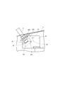
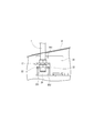
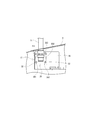
続いて、図3乃至図5はシグナルタワー10の固定構造を示した図である。特に、図3はシグナルタワー10が起立した姿勢の取り付け状態であり、図4はシグナルタワー10が前傾した姿勢の取り付け状態である。そして図5は、シグナルタワー10を外装カバー3内に収納する倒伏した姿勢の取り付け状態を示した図である。
シグナルタワー10は、図1に示すように、外装カバー3の屋根前端部右側に形成された切欠き部から突き出すようにして取り付けられている。従って、図3乃至図5の固定構造は、外装カバー3内の前方上部側面部に構成されている。このシグナルタワー10は、円柱形状のポール11の上方に表示部12(図1参照)が設けられ、下方には取付部13が設けられている。その取付部13は、ポール11の下端部分に取付用ブラケット21がナットを介して固定されたものである。
取付用ブラケット21の平面部には、ポール11を挟んだ左右の位置に貫通孔211,212が1箇所ずつ形成され、六角ヘッドのボルト22が通されている。すなわち、この取付用ブラケット21は、2個のボルト22によりネジ止め固定されるものである。一方、外装カバー3側には、取付用ブラケット21(すなわちシグナルタワー10)を固定するための被取付部として固定プレート31が設けられている。その固定プレート31には、ボルト22の締め付けが可能なネジ穴が複数形成されている。具体的には、図3及び図4に示すように4つのネジ穴311,312,313,314が形成されている。
これらのネジ穴311,312,313,314は、シグナルタワー10を異なる姿勢で取り付けるために形成されたものである。ネジ穴311,312が図3に示す起立姿勢の際に使用され、ネジ穴312,313が図4に示す前傾姿勢の際に使用され、ネジ穴312,314が図5に示す倒伏姿勢の際に使用される。本実施形態では、シグナルタワー10の姿勢を3パターンに変化させることができるが、ネジ穴312がいずれの姿勢の取り付けにも使用される共通のネジ穴になっている。そして、シグナルタワー10の固定構造は、作業機械ライン1の全ての工作機械5において共通である。
そこで、工作機械5は、工場への搬入や搬出の際には、シグナルタワー10が図5に示すように倒伏した姿勢で取り付けられる。すなわちシグナルタワー10は、搬送作業などの邪魔にならないように外装カバー3内に収められる。こうした点について、前記特許文献1には、搬入や搬出に際して折り畳みが可能なポール型のシグナルタワーが開示されている。確かにシグナルタワーを邪魔にならないように収納でき、取り扱いも便利である。しかし、その構造は複雑であり、しかも起立姿勢と折り畳んだ倒伏姿勢との間の切り換えしかできない。その点本実施形態では、シグナルタワー10を倒伏姿勢にして収納可能にしただけではなく、作業機械ライン1として設置された後は、図1に示すように起立姿勢や前傾姿勢になるようにシグナルタワー10の付け直しが可能であり、しかも極めて簡単な作業である。
ところで、複数のシグナルタワー10が並んだ場合の姿勢の変化は、必ずしも図1に示すように交互である必要はない。シグナルタワー10の姿勢変化は、作業者によって正確かつ確実に警告表示の確認ができることを目的とするものだからである。従って、工場内における作業機械ライン1の設置状況、作業者の立ち位置や作業手順などを考慮して決定すればよい。例えば、作業機械ライン1が複数セット横並びに設置されているような場合、作業者の位置から近い作業機械ライン1は図12に示す従来タイプにし、遠い作業機ライン1は図1に示すタイプにする。そして、中間に位置する作業機械ライン1は、他と区別するために、例えば作業者から近い4本は起立姿勢にし、遠い4本は前傾姿勢にする。また、作業者から見て工場内に存在するものが障害となってシグナルタワー10が見難いような場合には、その障害物を避けるようにした姿勢とすればよい。
本実施形態の機械ライン1によれば、様々な状況に応じてシグナルタワー10の姿勢を設定することができる。そして、シグナルタワー10の取り付けは、固定プレート31に対する取付用ブラケット21の向きを変えるだけでよく、しかも2本のボルト22の取り扱いだけでよい。また、固定プレート31には、起立姿勢のネジ穴311,312に加え、傾斜姿勢にはネジ穴313を、倒伏姿勢にはネジ穴314をそれぞれ1箇所ずつ追加した極めて簡素化された構成である。更に、新たな部品を必要とせず、既存のものに僅かな加工を加えただけで、極めて低コストでシグナルタワー10の姿勢変化による効果を得ることができる。
続いて、固定構造の変形例について説明する。先ず前記固定構造は、起立姿勢および倒伏姿勢に加えて一定角度の前傾姿勢でシグナルタワー10を取り付けることを可能にしたものである。これに対して図6乃至図8に示す第1変形例は、一定の範囲内で角度調整を可能にした固定構造である。この固定構造は、取付部15の取付用ブラケット23が揺動可能な状態で取り付けられるように構成されている。その取付用ブラケット23は、図6に示すように、支点となるボルト22を通す支点用貫通孔231が形成され、更にもう一方のボルト22側には湾曲した長孔形状の揺動用貫通孔232が形成されている。一方、固定プレート33は、図7に示すように、支点用貫通孔231を通したボルト22を締め付けるネジ穴331と、揺動用貫通孔232を通したボルト22を締め付けるネジ穴332、そして倒伏姿勢のためのネジ穴333が形成されている。
取付用ブラケット23は、2つのボルト22を緩めることで、支点用貫通孔231側のボルト22を支点とした揺動スライドが可能になる。そして、他方のボルト22が揺動用貫通孔231内を相対的に移動し、任意の位置で2つのボルト22が締め付けられ、図7に示すように斜めになった取付用ブラケット23が固定プレート33に固定される。この固定構造によれば、取付用ブラケット23を取り外すことなく一定の範囲内で任意の角度による調整が可能である。従って、シグナルタワー10を複数角度で前傾姿勢にすることができる。一方、収納する場合には取付用ブラケット23を取り外し、シグナルタワー10を図8に示すように横向きにし、ネジ穴331,333を使用して取付用ブラケット23をネジ止めして固定する。
次に、図9乃至図11は、固定構造の第2変形例を示した図である。この第2変形例は、一定の範囲内で高さ調整を可能にした固定構造である。この固定構造は、取付部17の取付用ブラケット25が昇降可能な状態で取り付けられるように構成されている。その取付用ブラケット25は、図9に示すように、ポール11を挟んだ左右の位置に上下方向に長い長孔形状の昇降用貫通孔251,252が形成されている。一方、固定プレート35は、図10に示すように、昇降用貫通孔251,252を通した2つのボルト22を締め付けるネジ穴351,352と、倒伏姿勢のためのネジ穴353が形成されている。
取付用ブラケット25は、2つのボルト22を緩めることで昇降スライドが可能になる。そして、ボルト22が昇降用貫通孔251,252内を相対的に移動し、任意の位置で2つのボルト22が締め付けられ、図10に示すような高さで取付用ブラケット25が固定プレート35に固定される。この固定構造によれば、取付用ブラケット25を取り外すことなく一定の範囲内で任意の高さによる調整が可能である。従って、シグナルタワー10を複数の高さの姿勢に変化させることができる。一方、収納する場合には取付用ブラケット25を取り外し、シグナルタワー10を図11に示すように横向きにし、ネジ穴352,353を使用して取付用ブラケット25をネジ止めして固定する。
よって、第1変形例1は角度の姿勢変化のみであり、第2変形例2は高さの姿勢変化のみであるが、どちらも揺動用貫通孔232または昇降用貫通孔251,252の範囲内で連続的に姿勢を変化させ、任意の角度や高さで固定させることができる。例えば図1に示す8台の工作機械5を4台ずつ2組に分け、各組のシグナルタワー10を同じように角度や高さが連続して変化するようにしてもよい。一体的に構成されている作業機械ライン1についてシグナルタワー10を2組に分けて識別することができ、警報表示されたシグナルタワー10を正確に確認することができる。ただし、これに限定されることはなく様々なパターンで姿勢を変化させることが可能である。
そして、シグナルタワー10の姿勢変化は、倒伏姿勢を除いて取付用ブラケット23,25を取り外すことなく揺動させたり上下にスライドさせるだけでよく、しかも2本のボルト22を緩めて再度締め直すだけでよい。また、固定プレート33,35には、3つのネジ穴331,332,333又はネジ穴351,352,353を形成した極めて簡素化された構成である。更に、新たな部品を必要とせず、既存のものに揺動用貫通孔232や昇降用貫通孔251,252を加えただけで、極めて低コストでシグナルタワー10の姿勢変化による効果を得ることができる。
以上、本発明の一実施形態について説明したが、本発明はこれらに限定されるものではなく、その趣旨を逸脱しない範囲で様々な変更が可能である。
例えば、前記実施形態ではシグナルタワー10を前傾させる場合についてだけ説明したが、後傾姿勢などであってもよい。
また、シグナルタワー10の姿勢変化は作業者によって確認しやすいことを目的としたが、加えて姿勢の違いにより工作機械5などの機能を識別できるようにしてもよい。
また、固定構造の第1変形例では支点用貫通孔231を通ったボルト22を支点としたが、ボドルとではなく固定ピンにして、倒伏姿勢までも可能な構成にしてもよい。
また、前述したことであるが、作業機械ライン1を構成する作業機械は工作機械5に限定されることなく実装機などであってもよく、工作機械5に関してもその機種が限定されるものではない。
例えば、前記実施形態ではシグナルタワー10を前傾させる場合についてだけ説明したが、後傾姿勢などであってもよい。
また、シグナルタワー10の姿勢変化は作業者によって確認しやすいことを目的としたが、加えて姿勢の違いにより工作機械5などの機能を識別できるようにしてもよい。
また、固定構造の第1変形例では支点用貫通孔231を通ったボルト22を支点としたが、ボドルとではなく固定ピンにして、倒伏姿勢までも可能な構成にしてもよい。
また、前述したことであるが、作業機械ライン1を構成する作業機械は工作機械5に限定されることなく実装機などであってもよく、工作機械5に関してもその機種が限定されるものではない。
1…作業機械ライン 2…ベース 3…外装カバー 4…前カバー 5…工作機械 10…シグナルタワー 11…ポール 12…表示部 13…取付部 21…取付ブラケット 22…ボルト 31…固定プレート 211,212…貫通孔 311,312,313,314…ネジ穴
Claims (7)
- 作業対象物に対して所定の作業を行う作業部を備えた作業機械が複数並べられ、前記作業機械の作業部に対して作業対象物の搬送を行う搬送装置を有し、前記各作業機械には可動状況を表示するシグナルタワーが設けられた作業機械ラインであり、
前記シグナルタワーは、上方に表示部が形成され下方に取付部が設けられた棒形状のものであり、前記取付部および前記作業機械側の被取付部は、前記シグナルタワーが複数の姿勢で固定可能な固定構造を構成するものであることを特徴とする作業機械ライン。 - 前記シグナルタワーの複数の姿勢は、前記シグナルタワーの傾きが異なる状態や、前記シグナルタワーの高さが異なる状態であることを特徴とする請求項1に記載の作業機械ライン。
- 前記シグナルタワーの取付部は前記作業機械の被取付部にネジ止めして固定されるものであり、前記シグナルタワーの取付部にはネジを通す一又は二以上の貫通孔が形成され、前記作業機械の被取付部は、前記シグナルタワーを複数の姿勢で固定させるための複数のネジ穴が形成されたものであることを特徴とする請求項1又は請求項2に記載の作業機械ライン。
- 前記取付部には前記貫通穴が2箇所に形成され、前記被取付部には3箇所以上にネジ穴が形成されたものであり、
前記シグナルタワーが所定の姿勢で固定される際に使用される2箇所の前記ネジ穴の一方が、他の姿勢で前記シグナルタワーが固定される際の前記ネジ穴として使用されるものであることを特徴とする請求項3に記載の作業機械ライン。 - 前記シグナルタワーの取付部は、支点用貫通孔と湾曲した長孔形状の揺動用貫通孔とが形成され、前記支点用貫通孔を通したネジを支点として揺動し、前記揺動用貫通孔に対する位置が相対的に変化するネジが所定の位置で締め付けられるようにしたものであることを特徴とする請求項3に記載の作業機械ライン。
- 前記シグナルタワーの取付部は、上下方向に長い長孔形状の昇降用貫通孔が形成され、前記昇降用貫通孔に対する位置が相対的に変化するネジが所定の位置で締め付けられるようにしたものであることを特徴とする請求項3に記載の作業機械ライン。
- 複数の前記作業機械は外観が統一され、同一の位置に前記シグナルタワーが固定されたものであり、隣同士の作業機械を比べた場合に互いのシグナルタワーの姿勢が異なるものであることを特徴とする請求項1乃至請求項6のいずれかに記載の作業機械ライン。
Priority Applications (2)
| Application Number | Priority Date | Filing Date | Title |
|---|---|---|---|
| PCT/JP2014/084535 WO2016103454A1 (ja) | 2014-12-26 | 2014-12-26 | 作業機械ライン |
| JP2016565806A JP6463378B2 (ja) | 2014-12-26 | 2014-12-26 | 作業機械ライン |
Applications Claiming Priority (1)
| Application Number | Priority Date | Filing Date | Title |
|---|---|---|---|
| PCT/JP2014/084535 WO2016103454A1 (ja) | 2014-12-26 | 2014-12-26 | 作業機械ライン |
Publications (1)
| Publication Number | Publication Date |
|---|---|
| WO2016103454A1 true WO2016103454A1 (ja) | 2016-06-30 |
Family
ID=56149542
Family Applications (1)
| Application Number | Title | Priority Date | Filing Date |
|---|---|---|---|
| PCT/JP2014/084535 Ceased WO2016103454A1 (ja) | 2014-12-26 | 2014-12-26 | 作業機械ライン |
Country Status (2)
| Country | Link |
|---|---|
| JP (1) | JP6463378B2 (ja) |
| WO (1) | WO2016103454A1 (ja) |
Citations (5)
| Publication number | Priority date | Publication date | Assignee | Title |
|---|---|---|---|---|
| US4984142A (en) * | 1989-07-11 | 1991-01-08 | Sirena S.P.A. | Optical indicator |
| JPH04300133A (ja) * | 1991-03-27 | 1992-10-23 | Pioneer Electron Corp | 自動組立ラインの警報装置 |
| JP2001022852A (ja) * | 1999-07-09 | 2001-01-26 | Akita Electronics Co Ltd | 設備稼働管理システム |
| JP2001195667A (ja) * | 2000-01-06 | 2001-07-19 | Fujita Seisakusho:Kk | 折り畳み式シグナルタワー |
| US20060097861A1 (en) * | 2004-10-22 | 2006-05-11 | Juergen Marquardt | Signaling apparatus, in particular a signaling column |
-
2014
- 2014-12-26 JP JP2016565806A patent/JP6463378B2/ja active Active
- 2014-12-26 WO PCT/JP2014/084535 patent/WO2016103454A1/ja not_active Ceased
Patent Citations (5)
| Publication number | Priority date | Publication date | Assignee | Title |
|---|---|---|---|---|
| US4984142A (en) * | 1989-07-11 | 1991-01-08 | Sirena S.P.A. | Optical indicator |
| JPH04300133A (ja) * | 1991-03-27 | 1992-10-23 | Pioneer Electron Corp | 自動組立ラインの警報装置 |
| JP2001022852A (ja) * | 1999-07-09 | 2001-01-26 | Akita Electronics Co Ltd | 設備稼働管理システム |
| JP2001195667A (ja) * | 2000-01-06 | 2001-07-19 | Fujita Seisakusho:Kk | 折り畳み式シグナルタワー |
| US20060097861A1 (en) * | 2004-10-22 | 2006-05-11 | Juergen Marquardt | Signaling apparatus, in particular a signaling column |
Also Published As
| Publication number | Publication date |
|---|---|
| JPWO2016103454A1 (ja) | 2017-10-05 |
| JP6463378B2 (ja) | 2019-01-30 |
Similar Documents
| Publication | Publication Date | Title |
|---|---|---|
| US10449619B2 (en) | System for processing a workpiece | |
| ES2954606T3 (es) | Dispositivo de control para su uso en una máquina herramienta de control numérico y máquina herramienta con un dispositivo de control | |
| US20210001508A1 (en) | Wood processing system | |
| AT521384A4 (de) | Automatisierter Vakuumgreifer und Verfahren zum sicheren Greifen von Bauteilen | |
| JP6669693B2 (ja) | 工作機械にて使用するハンドリング装置 | |
| EP3221078B1 (en) | System and method for processing holes in a work piece | |
| CN105828996A (zh) | 转塔刀架和具备转塔刀架的机床 | |
| CN103801976A (zh) | 自动搬运夹手总成 | |
| JPWO2016059718A1 (ja) | 加工機械のベース構造及び加工機械ラインを構築するベース設置方法 | |
| JP6420269B2 (ja) | シェルフ型ロボットを備えたプログレッシブ冷間成型機、工具自動交換据え付け装置及び工具カセットの自動交換方法 | |
| US20220395947A1 (en) | System for processing a workpiece | |
| JP6618544B2 (ja) | 多機能ワーク置き台モジュール | |
| JP6463378B2 (ja) | 作業機械ライン | |
| CN110640526A (zh) | 一种自动上下料的加工系统 | |
| CN203751818U (zh) | 自动搬运夹手总成 | |
| US9144870B2 (en) | Rotary pallet pool | |
| KR20190032235A (ko) | 공작 기계 상의 공구를 교환 및 삽입 또는 배치하기 위한 시스템과 이러한 시스템을 구비한 공작 기계 | |
| JP4963222B2 (ja) | 長尺のワークの3次元加工装置 | |
| KR101909973B1 (ko) | 2층구조의 가공기 소재 투입 및 취출 로봇 시스템 | |
| CN109227080B (zh) | 一种多功能机械手及回转平台 | |
| US11407074B2 (en) | Processing machine line | |
| EP2463183B1 (en) | Workpiece positioning device and production system using it | |
| CN115415706B (zh) | 一种焊接机器人工作站及其应用方法 | |
| JP7143131B2 (ja) | エンドエフェクタ装置および多関節ロボット | |
| JP7285107B2 (ja) | 回転工具装置および工作機械 |
Legal Events
| Date | Code | Title | Description |
|---|---|---|---|
| 121 | Ep: the epo has been informed by wipo that ep was designated in this application |
Ref document number: 14909058 Country of ref document: EP Kind code of ref document: A1 |
|
| ENP | Entry into the national phase |
Ref document number: 2016565806 Country of ref document: JP Kind code of ref document: A |
|
| NENP | Non-entry into the national phase |
Ref country code: DE |
|
| 122 | Ep: pct application non-entry in european phase |
Ref document number: 14909058 Country of ref document: EP Kind code of ref document: A1 |