WO2016103341A1 - 質量分析装置 - Google Patents
質量分析装置 Download PDFInfo
- Publication number
- WO2016103341A1 WO2016103341A1 PCT/JP2014/084054 JP2014084054W WO2016103341A1 WO 2016103341 A1 WO2016103341 A1 WO 2016103341A1 JP 2014084054 W JP2014084054 W JP 2014084054W WO 2016103341 A1 WO2016103341 A1 WO 2016103341A1
- Authority
- WO
- WIPO (PCT)
- Prior art keywords
- mass spectrometer
- flow path
- ions
- ion
- faims
- Prior art date
- Legal status (The legal status is an assumption and is not a legal conclusion. Google has not performed a legal analysis and makes no representation as to the accuracy of the status listed.)
- Ceased
Links
Images










Classifications
-
- G—PHYSICS
- G01—MEASURING; TESTING
- G01N—INVESTIGATING OR ANALYSING MATERIALS BY DETERMINING THEIR CHEMICAL OR PHYSICAL PROPERTIES
- G01N27/00—Investigating or analysing materials by the use of electric, electrochemical, or magnetic means
- G01N27/62—Investigating or analysing materials by the use of electric, electrochemical, or magnetic means by investigating the ionisation of gases, e.g. aerosols; by investigating electric discharges, e.g. emission of cathode
- G01N27/622—Ion mobility spectrometry
- G01N27/624—Differential mobility spectrometry [DMS]; Field asymmetric-waveform ion mobility spectrometry [FAIMS]
-
- H—ELECTRICITY
- H01—ELECTRIC ELEMENTS
- H01J—ELECTRIC DISCHARGE TUBES OR DISCHARGE LAMPS
- H01J49/00—Particle spectrometers or separator tubes
- H01J49/004—Combinations of spectrometers, tandem spectrometers, e.g. MS/MS, MSn
-
- H—ELECTRICITY
- H01—ELECTRIC ELEMENTS
- H01J—ELECTRIC DISCHARGE TUBES OR DISCHARGE LAMPS
- H01J49/00—Particle spectrometers or separator tubes
- H01J49/02—Details
- H01J49/04—Arrangements for introducing or extracting samples to be analysed, e.g. vacuum locks; Arrangements for external adjustment of electron- or ion-optical components
Definitions
- the present invention relates to a mass spectrometer equipped with an ion mobility separator.
- ions can be separated by the mass-to-charge ratio (m / z) of molecular ions in a vacuum, and ions can be separated and detected with high sensitivity and high accuracy.
- mass spectrometry the ions are separated for each mass-to-charge ratio (m / z).
- This mass spectrometry technique is generally used as a detector for liquid chromatograph (LC) and gas chromatograph (GC), and is used for liquid chromatography mass spectrometry (LC / MS) and gas chromatography mass spectrometry (GC / MS). The analysis method called is often used.
- tandem mass spectrometry, time-of-flight mass spectrometry, and Fourier transform-type mass spectrometry have been made possible by decomposing ions to be measured and measuring the decomposed ions to enable separation from other impurities.
- High-resolution mass spectrometers such as triple quadrupole mass spectrometers and high-sensitivity mass spectrometers such as quadrupole mass spectrometers have been developed, and mass spectrometers have been widely spread mainly in the bio and medical fields It's getting on.
- an ion mobility separation device takes advantage of the fact that the movement speed of ions in the gas phase varies depending on the three-dimensional structure of molecular ions in the gas phase under atmospheric pressure. Ions are separated. Therefore, structural isomer ions having the same mass-to-charge ratio (m / z), which are difficult to separate by mass spectrometry, can be separated in principle.
- m / z mass-to-charge ratio
- Patent Document 1 shows an example of an apparatus in which a FAIMS and a mass spectrometer are combined.
- the FAIMS is attached to the front stage of the mass spectrometer, and the user can attach and remove the FAIMS.
- Patent Document 2 shows another example of FAIMS and a mass spectrometer.
- the internal electrode of the FAIMS has a cylindrical shape and can be rotated. In this configuration, it is shown that a mode in which mass analysis is performed after ion separation (hereinafter, ion separation mode) and an MS mode in which ions are not separated in FAIMS can be switched by rotation of the internal electrode of FAIMS. In the MS mode, a cylindrical flow path vacated inside the internal electrode can also pass through.
- the measurement sample does not require the FAIMS ion separation function, it is more effective to remove the FAIMS. This is because, as described above, the loss of ions occurs only by wearing the FAIMS. However, when the user manually removes FAIMS as in Patent Document 1, it usually takes several minutes to several tens of minutes. As described above, it is troublesome to attach / remove each measurement sample, and there is a concern that the throughput of measurement may be reduced.
- the present invention provides a mass spectrometer for efficiently performing an analysis using an ion mobility separator.
- a mass spectrometer includes an ion source, an ion mobility separation unit, a mass spectrometer, and a first flow path for introducing ions from the ion source to the mass spectrometer through the ion mobility separation unit.
- a blocking mechanism that selectively blocks passage through the path, and the inlet of the first channel and the inlet of the second channel are arranged at an equal distance from the ion source. .
- the blocking mechanism can be configured by shielding means by an electric field, gas, or object, or a combination thereof.
- the second flow path is blocked by a blocking mechanism. Shut off and allow ions to pass through the first channel.
- a blocking mechanism is used. The second channel is blocked and ions are passed through the first channel.
- high-efficiency, high-throughput, high-sensitivity analysis is realized in an apparatus using an ion mobility separator and a mass spectrometer.
- the schematic diagram which shows the structural example of the mass spectrometer made into MS mode The schematic diagram which shows the structural example of the mass spectrometer made into ion separation mode.
- the schematic diagram which shows the structural example of the mass spectrometer made into MS mode The schematic diagram which shows the structural example of the mass spectrometer made into ion separation mode.
- the schematic diagram which shows the structural example of the mass spectrometer made into MS mode The schematic diagram which shows the structural example of the mass spectrometer made into MS mode.
- the schematic diagram which shows the structural example of the mass spectrometer made into ion separation mode The schematic diagram which shows the structural example of the mass spectrometer made into MS mode.
- the schematic diagram which shows the structural example of the mass spectrometer made into ion separation mode The schematic diagram which shows the structural example of the mass spectrometer made into MS mode.
- the schematic diagram which shows the structural example of the mass spectrometer made into ion separation mode The schematic diagram which shows the structural example of the mass spectrometer
- the schematic diagram which shows the structural example of the mass spectrometer made into MS mode The schematic diagram which shows the structural example of the mass spectrometer made into MS mode.
- the schematic diagram which shows the structural example of the mass spectrometer made into ion separation mode The schematic diagram which shows the structural example of the mass spectrometer made into MS mode.
- the schematic diagram which shows the structural example of the mass spectrometer made into MS mode The schematic diagram which shows the structural example of the mass spectrometer made into MS mode.
- FIG. 1A is a schematic diagram showing a general configuration of FAIMS.
- the FAIMS 50 includes a first electrode 51 and a second electrode 52 that are two flat plate electrodes made of metal. The distance between these two electrodes is about 0.1 mm to several mm, and the electrode length corresponding to the distance over which ions fly is about several tens mm.
- the electrode length corresponding to the distance over which ions fly is about several tens mm.
- there are FAIMS having a further miniaturized structure and there are also those having a distance between electrodes of about several tens of ⁇ m.
- FAIMS includes an AC voltage power supply 53, a DC voltage power supply 54, and a bias voltage power supply 57.
- an alternating voltage power supply 53 is used, and a separation voltage (or a dispersion voltage or a separation voltage: SV) obtained by superimposing high-frequency voltages is applied to the first electrode 51, whereby the first electrode 51 and the second electrode 51 A high frequency electric field is applied between the electrodes 52.
- the separation voltage As an example of the separation voltage shown in FIG. 1B, the separation voltage (SV) is applied so that a high voltage (plus voltage) and a low voltage (minus voltage) are repeatedly applied for a certain period and become zero if time-averaged. Is done.
- the separation voltage has a voltage amplitude of several hundred volts to several kilovolts. Further, by applying a compensation voltage (or correction voltage, or compensation voltage: CV), which is a DC voltage generated by the DC voltage power supply 54, to the second electrode 52, the ion trajectory 56 of a specific ion 55 is corrected. Thus, it is possible to transmit only specific ions 55 and exclude other ions.
- This compensation voltage is about ⁇ 100V to + 100V. Note that a DC voltage from the DC voltage power supply 54 can be applied to the first electrode 51. Similarly, a separation voltage can be applied to the second electrode 52.
- the present invention can be implemented in the same form not only with FAIMS but also with other ion mobility separation devices, and application of the present invention is not limited to FAIMS.
- a mass spectrometer having a first ion channel (ion separation mode) that passes through FAIMS and a second ion channel (MS mode) that does not pass through FAIMS
- ion separation mode a mode in which only mass spectrometry is performed without passing through FAIMS
- ion separation mode is a mode in which ions are separated by FAIMS and further mass spectrometry is performed.
- the MS mode all ions can be passed through the mass spectrometer without selectivity, so that the target molecule can be searched and sensitive detection can be performed.
- the ions can be detected with high sensitivity and high S / N.
- mass spectrometry can be performed with high efficiency by properly using the analysis modes as described in the present embodiment.
- a first embodiment will be described.
- physical means that is, a shutter, is used as a blocking mechanism for selectively blocking the passage of ions from the ion source in the first channel or the second channel and switching the analysis mode.
- a shielding part such as is used.
- FIG. 2 is a diagram for explaining the configuration of a mass spectrometer using FAIMS, which is an ion mobility separator, and a mass spectrometer. Ions generated by the ion source 1 are analyzed and detected in two analysis modes. One is an ion separation mode in which mass analysis is performed by the mass spectrometer 11 after ion separation in the FAIMS2 which is an ion mobility separation device, and the other is mass spectrometry by the mass spectrometer 11 without performing ion separation in the FAIMS2. MS mode.
- the control unit 10 controls each component of the FAIMS and the mass spectrometer, and is configured by an information processing device such as a personal computer.
- the control unit 10 includes a central processing unit, an auxiliary storage device, a main storage device, a display unit 18 and an input unit 19.
- the central processing unit is constituted by a processor such as a CPU (or also called a calculation unit).
- the auxiliary storage device is a hard disk, and the main storage device is a memory.
- the display unit 18 is a display or the like, and displays an analysis spectrum and results, and analysis conditions.
- the input unit 19 is a keyboard, a pointing device (such as a mouse), and the like, and can input analysis conditions and the like.
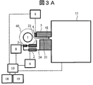
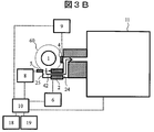
- FIG. 3A and FIG. 3B are diagrams showing the mass spectrometer of the present example, and are schematic partial cross-sectional views of the device viewed from above.
- 3A shows the MS mode
- FIG. 3B shows the ion separation mode. Switching between these two analysis modes, that is, switching of the sample ion flow path, is performed by a blocking mechanism using the shielding unit 4 and the shielding unit 5.
- the sample ions ionized by the ion source 1 enter from one of the ion introduction ports 23 and 25 according to the analysis mode, and pass through one of the channels 21 and 24. Thereafter, the ions pass through the flow path 21 formed by the inlet electrode 3 and enter the mass spectrometer 11 for analysis.
- the flow path 21 formed by the inlet electrode 3 serves as a partition between atmospheric pressure and vacuum, and has a cylindrical shape with a diameter of approximately 0.1 mm to 1 mm.
- the FAIMS 2 is applied with the separation voltage, the compensation voltage, and the bias voltage as described with reference to FIG. 1 by the power source 6 controlled by the control unit 10. Only one power source 6 is shown for simplicity of illustration.
- the mass spectrometer 11 performs mass separation / detection according to the mass-to-charge ratio (m / z) of ions.
- ions enter from the inlet 23, pass through the flow path 21 without passing through the FAIMS 2, and enter the mass spectrometer 11 according to the ion trajectory 41.
- ions enter from the introduction port 25, pass through the flow path 24 passing through the FAIMS 2 and the flow path 21 thereafter, and enter the mass spectrometer 11 according to the ion trajectory 42.
- the channel 24 and the channel 21 are finally integrated into one channel 21 and connected to the mass spectrometer.
- Switching between the two analysis modes that is, whether ions are introduced from the introduction port 23 or the introduction port 25 is performed by driving the shielding unit 4 and the shielding unit 5.
- the shielding part 4 is opened and the shielding part 5 is closed.
- ions pass from the inlet 23 through the ion trajectory 41 and are introduced into the mass spectrometer 11.
- the shield 4 is closed and the shield 5 is open.
- ions pass from the inlet 25 through the ion trajectory 42 and are introduced into the mass spectrometer 11.
- the shielding unit 4 is driven by the driving unit 9 controlled by the control unit 10, and the shielding unit 5 is driven by the driving unit 8 controlled by the control unit 10.
- the shielding unit can use a shutter, a shielding plate, a lid, a stopper, or an existing technology equivalent thereto, and may have any configuration that can block gas and ions.
- a sealable structure for example, an existing sealing technique / sealing technique such as a rubber ring is used.
- the shielding unit can be driven manually or can be automatically controlled by the control unit 10. As in the present embodiment, by using an existing shielding technique such as a shutter, shielding is possible with a relatively simple configuration.
- the mass spectrometer 11 is evacuated by a rotary pump or a turbo molecular pump.
- the degree of vacuum in the analysis section is 10 ⁇ 5 to 10 ⁇ 6 Torr.
- FIG. 4 is a partial cross-sectional schematic view of the mass spectrometer of this example as viewed from the lateral direction.
- the ion source 1 is, for example, electrospray ionization (ESI)
- ESI electrospray ionization
- a sample solution is fed from the upper side to the lower side of the figure, and a nebulizer gas and a heating gas for spraying the sample solution flow from the upper side to the lower side.
- the ions 7 sprayed and generated below the ion source 1 are bent, for example, by 90 degrees toward the introduction port 23, and are introduced into the mass spectrometer 11 through the flow path 21.
- it is similarly bent 90 degrees and introduced.
- the ion source 1 can introduce ions into any introduction port even if there are two or more introduction ports. It is desirable that the plurality of inlets be arranged at the same distance from the ion source 1.
- the equivalent distance is a distance at which the amount of ions introduced from the ion source 1 to each inlet can be regarded as equivalent.
- a plurality of inlets are arranged on a concentric circle 60 centered on the ion source 1.
- the same amount of ions can be introduced from the ion source into any inlet.
- ion introduction is possible regardless of the direction of the concentric circle 60 in the introduction port. This is apparent from the arrangement of FIG.
- Examples of ionization methods performed in the ion source 1 include electrospray ionization (ESI), atmospheric pressure chemical ionization (APCI), matrix-assisted laser desorption ionization (MALDI), desorption electrospray ionization (DESI), and atmospheric pressure photoionization.
- ESI electrospray ionization
- APCI atmospheric pressure chemical ionization
- MALDI matrix-assisted laser desorption ionization
- DESI desorption electrospray ionization
- APPI atmospheric pressure photoionization
- the ion mobility separator including FAIMS and DMS can be operated under atmospheric pressure or in vacuum.
- the mass spectrometer 11 may be a known mass spectrometer.
- mass spectrometers such as three-dimensional ion traps and linear ion traps, quadrupole filter mass spectrometers (Q filter), triple quadrupole mass spectrometers, time-of-flight mass spectrometers (TOF / MS) , Fourier transform ion cyclotron resonance mass spectrometer (FTICR), orbitrap mass spectrometer, magnetic field type mass spectrometer and the like.
- FTICR Fourier transform ion cyclotron resonance mass spectrometer
- orbitrap mass spectrometer magnetic field type mass spectrometer and the like.
- FIG. 5 is a schematic diagram showing an example of mass spectrometry data obtained by LC / MS analysis.
- mass spectra are acquired for each LC retention time, and as shown in FIG. 5, three-dimensional data consisting of the three axes of LC retention time, m / z, and ion intensity is acquired.
- Two analysis methods using the present invention will be described. One is when the target analysis ion is determined in advance by FAIMS, and the other is when it is not.
- FAIMS ion separation mode
- only target ions are allowed to pass through and mass analysis is performed with a mass spectrometer.
- FAIMS has different analysis voltage conditions depending on ion species, it is desirable to investigate the analysis conditions in advance.
- FAIMS analysis conditions may be registered in a database, that is, described and prepared in advance as a list of analysis ions as in list b. By having this list, it is not necessary to search for FAIMS analysis conditions, and target ions can be analyzed immediately. If the analysis conditions of FAIMS for analysis ions are unknown, it is necessary to search over time.
- the list of analysis ions only the target ions can be analyzed more accurately by including the LC retention time in addition to the list a as in the list c.
- the list of analysis ions may be a list including m / z, LC retention time, FAIMS separation voltage, and compensation voltage.
- MS / MS analysis is used using an ion dissociation technique. By this method, S / N is improved and analysis can be performed with higher accuracy.
- Ion dissociation is a method of analyzing fragment ions generated by ion dissociation by collision-induced dissociation (CID) or the like. For example, in a triple quadrupole mass spectrometer, it is a method called multi-reaction monitoring (MRM).
- MRM multi-reaction monitoring
- a gas flow is used as a blocking mechanism for selectively blocking the passage of ions from the ion source in the first channel or the second channel and switching the analysis mode.
- FIG. 6A and 6B are partial cross-sectional schematic diagrams of the mass spectrometer of the present example, FIG. 6A is a diagram showing an MS mode, and FIG. 6B is a diagram showing an ion separation mode.
- a blocking mechanism that blocks ions from passing through the flow path uses gas. By flowing a gas from the mass spectrometer side toward the ion source side, introduction of ions and neutral molecules into the mass spectrometer can be blocked or prevented.
- the gas for blocking the introduction of ions is introduced through the pipe 14 using the gas control unit 12.
- a gas flow 32 is generated from the mass spectrometer 11 side to the ion source 1 side at the position of the introduction port 25, so that ions and neutral gas from the ion source 1 are fed from the introduction port 25 to FAIMS 2.
- sample ions generated by the ion source 1 are introduced only from the inlet 23 and enter the mass spectrometer 11 along the ion trajectory 41 passing through the flow path 21 for analysis.
- the introduction port 23 and the introduction port 25 are circular, and the hole diameter is about several mm to 10 mm. If the gas flow rate from the gas control unit 12 is about 0.1 L / min to 10 L / min, ions and gas can be shut off.
- a gas flow 31 from the inlet 23 toward the ion source 1 can be generated by introducing the gas through the pipe 15 using the gas control unit 13.
- sample ions are introduced from the inlet 25 and introduced into the mass spectrometer 11 along the ion trajectory 42 passing through the flow path 24.
- control unit 10 the display unit 18, the input unit 19, and the FAIMS power supply 6 shown in FIGS. 3A and 3B are not shown in FIGS. 6A and 6B for the sake of simplicity, but are the same as in the first embodiment. Used for.
- an electric field is used as a blocking mechanism for selectively blocking the passage of ions from the ion source in the first channel or the second channel and switching the analysis mode.
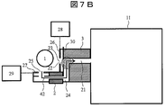
- FIG. 7A and 7B are schematic partial cross-sectional views of the mass spectrometer of the present embodiment
- FIG. 7A is a diagram showing an MS mode
- FIG. 7B is a diagram showing an ion separation mode.
- this is a method of switching the analysis mode by blocking the ion flow by applying a voltage to the electrode 26 and the electrode 27 arranged at the inlet of the flow path. Since the polarity of the power supply voltage differs depending on whether the sample ions are positive ions or negative ions, this embodiment will be described with an example of positive ion analysis. If it is a negative ion, it can be implemented in a similar manner by switching the power supply voltage between positive and negative.
- a power source 28 is connected to the electrode 26, and a power source 29 is connected to the electrode 27, and a DC voltage can be applied to each electrode.
- the voltage difference of the electrode 27 with respect to the spray tube of the ion source 1 is important. This is because spraying by electrospray occurs due to a potential difference between the spray tube and the electrode 27 (or electrode 26). Depending on the distance between the two electrodes of the spray tube and the electrode 27 (or the electrode 26), for example, if the distance is about 1 to 30 mm, the potential difference between the two electrodes is applied by applying about 1000 to 6000 V as an electrostatic spray. Occurs and ionization takes place.
- the potential difference becomes 4000V and electrospray ionization is performed. Therefore, if the voltage difference between the spray tube and the electrode 27 is 1000 V or less, electrostatic spraying does not occur, and ions on the inlet 27 side can be blocked. That is, for example, a spray tube of +5000 V, +1000 V to the electrode 26, and 4000 V or more, for example, +5000 V, should be applied to the electrode 27. At this time, the potential difference between the spray tube and the electrode 27 becomes 0, and the ion can be blocked without being introduced from the introduction port 25 on the electrode 27 side.
- the spray tube + 5000V the electrode 26 may be + 5000V, and the electrode 27 may be + 1000V.
- the potential difference between the spray tube and the electrode 26 becomes 0, and the ions can be blocked without being introduced from the introduction port 23 on the electrode 26 side.
- the electrode 26 it is desirable to place another electrode 30 after the electrode 26. This is because, in the ion separation mode shown in FIG. 7B, ions entering from the introduction port 25 pass through the vicinity of the electrode 26 through the ion trajectory 42. At that time, since the electrode 26 is 5000 V and the inlet electrode 3 is typically about 100 V, when ions pass through the region 22 in the vicinity of the electrode 26, the ion trajectory may be bent and ion loss may occur. . For this reason, by installing the electrode 30 at the subsequent stage of the electrode 26 and applying a voltage of the same level as that of the inlet electrode 3 (for example, about 100 V), ions can pass through the ion trajectory 42 without loss. . This electrode 30 may be at the same potential as the inlet electrode 3.
- the electrode 30 may be integrated with the inlet electrode 3. Any structure may be used as long as an electric field generated when a high voltage is applied to the electrode 26 does not affect the region 22 through which ions pass.
- the electrodes 26, 27, and 30 are made of a conductor such as metal, and have a structure in which a circular hole is opened at the center and ions pass through the hole.
- another electrode is installed between the electrode 26 and the electrode 30 and a voltage higher than that of the electrode 26 is applied thereto, thereby introducing the inlet. It is possible to block ions from 23.
- another electrode in the subsequent stage of the electrode 27, the introduction of ions from the introduction port 25 can be similarly blocked.
- This method blocks the passage of ions by arranging electrodes in the flow paths 21 and 24 through which ions pass and applying a voltage to the electrodes to form a potential barrier higher than the potential of the ions. is there.
- the introduction of ions can be blocked by the electric field generated by applying a voltage to the electrodes, and the analysis mode can be switched. Since the voltage can be controlled at a high speed within one second, there is a merit that the analysis mode can be switched at a high speed as compared with the methods described so far, and a high throughput analysis is possible.
- the gas flow by the exhaust mechanism is used as a blocking mechanism for selectively blocking the passage of ions from the ion source in the first channel or the second channel and switching the analysis mode. Is used.
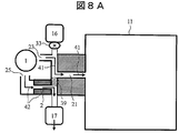
- FIG. 8A and 8B are partial cross-sectional schematic views of the mass spectrometer of the present example, FIG. 8A is a diagram showing an MS mode, and FIG. 8B is a diagram showing an ion separation mode.
- the exhaust part 16 is connected to the flow path following the introduction port 23, in the illustrated example, downstream of the introduction port 23.
- the exhaust part 17 is connected to the flow path following the inlet 25 in the illustrated example on the downstream side of the FAIMS.
- the exhaust parts 16 and 17 may be anything that can generate a gas flow, such as a fan or an exhaust pump. In order to control the flow rate finely and accurately, it is desirable to provide a flow meter and a gas control unit.
- the exhaust unit 17 is operated, and ions passing through the FAIMS are exhausted (sucked) by the exhaust unit 17 and do not reach the mass spectrometer 11.
- the other exhaust part 16 is either in a state where the pump is stopped or in a state where the pump is operating but the on-off valve 33 is closed. There is no gas flow to the The exhaust speed (or exhaust amount) of the exhaust unit 17 is adjusted to be the same as the inflow speed (or inflow amount) flowing from the introduction port 25.
- the flow velocity in the region 39 of the flow path on the FAIMS side becomes 0 when viewed from the merging point where the flow path from the introduction port 23 and the flow path from the introduction port 25 merge and become one (no wind)
- gas and ions do not go back and forth above and below the region 39.
- ions entering from the inlet 23 are introduced into the mass spectrometer 11 along the ion trajectory 41.
- ions entering from the inlet 25 are exhausted to the exhaust unit 17 and disappear.
- the exhaust unit 16 is operated, and ions introduced from the introduction port 23 are exhausted by the exhaust unit 16 and do not reach the mass spectrometer 11.
- the other exhaust part 17 is either in a state where the pump is stopped or in a state where the pump is operating but the on-off valve is closed. No gas flow occurs.
- the exhaust speed of the exhaust unit 16 is adjusted to be the same as the inflow speed flowing from the introduction port 23. This is because the flow velocity in the region 40 of the flow channel on the introduction port 23 side becomes zero (no wind) when viewed from the merging point where the flow channel from the introduction port 23 and the flow channel from the introduction port 25 merge together.
- the gas and ions do not go back and forth above and below the region 40.
- ions entering from the inlet 25 are introduced into the mass spectrometer 11 after passing through the FAIMS 2.
- ions entering from the inlet 23 are exhausted to the exhaust part 16 and disappear.
- FIG. 9 is a schematic diagram illustrating an example of another mode of the present embodiment. As shown in the figure, it is possible to operate with only one exhaust part 35 instead of two exhaust parts constituting the blocking mechanism.
- On-off valves (or valves) 33 and 34 are attached in the middle of the piping, and the gas flow can be switched and controlled by opening and closing each separately.
- the exhaust speed can be adjusted by the opening ratio of the on-off valve. As shown in FIG. 8A, it is important to adjust the exhaust speed by the exhaust unit 35 so that the flow velocity in the region 39 becomes zero.
- the gas flow can block not only ions but also neutral molecules and other gas flows, so that highly sensitive measurement is possible.
- a fifth embodiment will be described.
- the analysis mode is switched by selectively blocking the passage of ions from the ion source in the first flow path or the second flow path.
- a blocking part is used as a blocking mechanism.
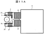
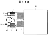
- FIGS. 10A and 10B are schematic partial cross-sectional views of the mass spectrometer of the present embodiment, FIG. 10A is a diagram showing an MS mode, and FIG. 10B is a diagram showing an ion separation mode. This is a method of switching between a total of three modes, MS mode and two ion separation modes.
- each blocking unit 5 and 36 are installed as blocking mechanisms, respectively. Further, a blocking unit 4 is installed in the flow path that does not pass through the FAIMS. Although not shown, each blocking unit is connected to a driving unit and can be operated by the control unit 10 as in the previous embodiments.
- FIG. 10A shows an MS mode that does not pass through the FAIMS, the blocking section 4 is open, and ions are introduced along the ion trajectory 41 through the flow path 21 into the mass spectrometer 11. At this time, since the blocking unit 5 and the blocking unit 36 are closed, ion introduction into the FAIMS 2 and 37 is not performed.
- FIG. 10B shows an ion separation mode in which only the FAIMS 37 passes ions. Although the blocking units 4 and 5 are closed, the blocking unit 36 is open, and ions can pass only to the FAIMS 37. Ions passing through the inlet 25 pass through the FAIMS 37 and are introduced into the mass spectrometer 11 along the ion trajectory 42 and analyzed. That is, the blocking mechanism selectively allows one of the passage of ions from the ion source in the first FAIMS 2, the passage in the second FAIMS 37, or the passage of the introduction port 23, and blocks the other.
- FAIMS There are two main purposes for mounting two FAIMS. One is for cleaning and maintaining the FAIMS, and the other is for providing FAIMS with different resolutions.
- For the first cleaning / maintenance two FAIMS of the same structure are installed, one is cleaned / maintained or stocked as a spare, and another FAIMS is used for analysis.
- this method even when a failure occurs in the FAIMS being analyzed or when cleaning is required, it is not necessary to stop the analysis, and analysis can be performed immediately with another FAMS. During analysis, FAIMS can be maintained and cleaned. This method eliminates the need to stop the analysis accompanying the maintenance of the FAIMS, thereby improving the analysis throughput.
- FAIMS with different resolutions. For example, if FAIMS having two different flat electrode distances constituting the FAIMS is installed, analysis with different resolution becomes possible.
- the resolution is mainly determined by the distance or length of the plate electrodes constituting the FAIMS. For example, by installing two FAIMS with a 0.5 mm interval and a 1 mm interval, it is possible to acquire data of different resolutions and ion amounts. Become. It is also effective to install two different FAIMS when the length of the FAIMS is about 10 mm to about 100 mm. Furthermore, one has a configuration in which a reaction sample is allowed to flow inside FAIMS.
- FIG. 11A and 11B are diagrams showing another configuration example of the present embodiment.
- the FAIMS are arranged symmetrically.
- FIG. 11A shows the MS mode
- FIG. 11B shows the ion separation mode.
- the content of implementation is the same as the example of FIG. 10A and FIG. 10B.
- the inlets 23, 25, and 30 are arranged in three directions of the ion source, respectively.
- the configuration using two FAIMS has been described.
- the three channels of the MS mode and the two FAIMS ion separation modes are arranged on the same plane.
- all the channels need not necessarily be on the same plane.
- the method for switching the analysis mode in this example can also be implemented by a method using a gas, an electric field, and an exhaust part.
- the number of FAIMS is not limited to two, and three or more can be implemented in the same manner.
- FIG. 12 is a partial cross-sectional schematic diagram showing the MS mode of the mass spectrometer of the present embodiment.
- 3A and 3B shown in the first embodiment is deformed so that ions smoothly flow from the flow path 24 to the flow path 21.
- This channel structure is expected to efficiently introduce ions into the mass spectrometer 11.
- Other detailed implementation methods are the same as those in the first embodiment.
- a seventh embodiment will be described. In the embodiments so far, there is one channel connected to the mass spectrometer 11, but in this embodiment, there are two channels.
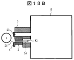
- FIGS. 13A and 13B are schematic partial cross-sectional views of the mass spectrometer of the present embodiment
- FIG. 13A is a diagram showing an MS mode
- FIG. 13B is a diagram showing an ion separation mode.
- the shielding part 4 of the blocking mechanism that opens and closes the inlet 23 is open, ions entering from the inlet 23 are introduced into the mass spectrometer 11 through the flow path 21.
- the shielding portion 5 that opens and closes the inlet 25 is closed, ions are not introduced into the inlet 25.
- FIG. 13A since the shielding part 4 of the blocking mechanism that opens and closes the inlet 23 is open, ions entering from the inlet 23 are introduced into the mass spectrometer 11 through the flow path 21.
- the shielding portion 5 that opens and closes the inlet 25 is closed, ions are not introduced into the inlet 25.
- FIG. 13A since the shielding part 4 of the blocking mechanism that opens and closes the inlet 23 is open, ions entering from the inlet 23
- the introduction port 23 since the introduction port 23 is closed and the introduction port 25 is open, ions entering from the introduction port 25 are introduced into the mass spectrometer 11 through the FAIMS 2 and the flow path 24. Thereby, ion separation using FAIMS becomes possible.
- the flow channel 21 and the flow channel 24 are connected to the mass spectrometer in parallel.
- the flow path inner diameter of the inlet electrode 3 is about 1 mm or less, and the distance between the flow paths 21 and 24 is about several mm. For this reason, ions in the two flow paths are incident at a distance of about 5 mm. For this reason, it is desirable that an ion focusing electrode 44 is attached to the subsequent stage of the introduction port electrode 3.
- the ion focusing electrode 44 is a funnel-type electrode to which a DC voltage is applied, or an existing ring-type ion guide in which a plurality of ring electrodes are arranged and an AC voltage is alternately applied, ions can be focused. Further, as shown in FIG. 14, ions can be converged by a known multi-polar ion guide 45 such as a quadrupole or an octupole.
- FIG. 14 is a diagram showing another configuration example of the present embodiment.
- the shielding parts 4 and 5 constituting the blocking mechanism are installed not on the ion source side but on the mass spectrometer 11 side.
- the mass spectrometer 11 side since there is a shielding part on the mass spectrometer 11 side, it can be expected that the flow path can be shielded with higher confidentiality.
- the MS mode is shown in the figure, the ion separation mode has the same configuration as the previous embodiments.
- FIG. 15 is a diagram showing another configuration example of the present embodiment.
- the introduction port 23 and the introduction port 25 are attached to the ion source 1 at an angle different by 90 degrees.
- Other configurations are the same as those in the previous embodiments.
- the figure shows the MS mode.
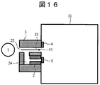
- FIG. 16 is a diagram showing another configuration example of the present embodiment.
- the number of the inlets 23 from the ion source 1 is one, but after that, the flow path 21 and the flow path 24 are separated. That is, the channel 21 and the channel 24 share the introduction port 23.
- FAIMS 2 is attached to the flow path 24.
- the shielding parts 4 and 5 constituting the blocking mechanism are installed on the mass spectrometer 11 side. The mode is switched by selectively driving the shielding units 4 and 5.
- mode switching can be similarly performed by using ion shielding by gas and ion shielding by electric field, which have been described so far, instead of the shielding units 4 and 5.
- this invention is not limited to the above-mentioned Example, Various modifications are included.
- the above-described embodiments have been described in detail for easy understanding of the present invention, and are not necessarily limited to those having all the configurations described.
- a part of the configuration of one embodiment can be replaced with the configuration of another embodiment, and the configuration of another embodiment can be added to the configuration of one embodiment.
Landscapes
- Chemical & Material Sciences (AREA)
- Physics & Mathematics (AREA)
- Analytical Chemistry (AREA)
- Spectroscopy & Molecular Physics (AREA)
- Health & Medical Sciences (AREA)
- Electrochemistry (AREA)
- Chemical Kinetics & Catalysis (AREA)
- Life Sciences & Earth Sciences (AREA)
- Biochemistry (AREA)
- General Health & Medical Sciences (AREA)
- General Physics & Mathematics (AREA)
- Immunology (AREA)
- Pathology (AREA)
- Other Investigation Or Analysis Of Materials By Electrical Means (AREA)
- Electron Tubes For Measurement (AREA)
Abstract
Description
第1の実施例について説明する。本実施例では、イオン源からのイオンの第1の流路中の通過あるいは第2の流路中の通過を選択的に遮断して分析モードを切り替えるための遮断機構として物理的な手段すなわちシャッターなどの遮蔽部を用いる。
FAIMSで分析する試料イオンが決まっている場合、そのイオン緒m/zは、図5に示すように、予め分析イオンのリストaとして準備しておく。このリストは、予めユーザーが作成する、もしくはFAIMSで分析するイオンのm/zのリストがデータベースに登録されているのであればそれを用いることが可能である。このリストやデータベースは、制御部10の内部にあり、制御部10により管理されている。このリストの一例としては、リストaのように分析したい試料イオンのm/zが書かれているものである。分析手順は、通常はMSモードでイオンの質量スペクトルを取得することでターゲットとなるイオンを探索し、このリストaにあるm/zのイオンのピークが検出されたら、イオン分離モードに切り替えて分析する。例えば、時間t1ではリストのm/z=181.1のイオンAが検出されたため、イオンAをイオン分離モードで分析する。
分析イオンが予め決まっていない場合は、MSモードで分析している時にある基準を設けてそれを満たせば、イオン分離モードで分析する方法を用いる。
予め決められている閾値以上のイオン量のピークが検出されたら、イオン分離モードで分析する。閾値は、予めユーザーが指定する。また閾値以上のピークが複数ある場合には、イオン量の高いイオンから優先して分析する。さらにノイズイオンなどをリストに記載しておくことで、そのノイズイオンの量が閾値以上であっても、分析対象から除外することが可能である。
質量スペクトルのS/N又はS/Bが予め設定した閾値以下のピークを検出した場合に、イオン分離モードで分析する。本分析の目的は、FAIMSを用いた分析によりノイズの低減による、S/Nの向上である。
第2の実施例について説明する。本実施例では、イオン源からのイオンの第1の流路中の通過あるいは第2の流路中の通過を選択的に遮断して分析モードを切り替えるための遮断機構としてガスの流れを用いる。
第3の実施例について説明する。本実施例では、イオン源からのイオンの第1の流路中の通過あるいは第2の流路中の通過を選択的に遮断して分析モードを切り替えるための遮断機構として電界を用いる。
第4の実施例について説明する。本実施例では、イオン源からのイオンの第1の流路中の通過あるいは第2の流路中の通過を選択的に遮断して分析モードを切り替えるための遮断機構として排気機構によるガスの流れを用いる。
第5の実施例について説明する。本実施例では、複数のFAIMSを搭載した構成において、イオン源からのイオンの第1の流路中の通過あるいは第2の流路中の通過を選択的に遮断して分析モードを切り替えるための遮断機構として遮断部を用いる。
第6の実施例について説明する。図12は、本実施例の質量分析装置のMSモードを示す一部断面模式図である。第1の実施例で示した図3A、図3Bの流路を変形させ、流路24から流路21へ滑らかにイオンが流れる構造になっている。この流路構造により、イオンの質量分析計11への導入が効率よく行われることが期待される。その他、詳細な実施方法は、第1の実施例と同様である。
第7の実施例について説明する。これまでの実施例では、質量分析計11へ繋がる流路が1つであったが、本実施例は流路が2つの例である。
2 FAIMS
3 導入口電極
4 遮蔽部
5 遮蔽部
6 FAIMS電源
7 イオン
11 質量分析計
12,13 ガス制御部
16,17 排気部
20 電極
23 導入口
25 導入口
26,27 電極
30 電極
33,34 開閉弁
44 イオン収束電極
45 多重極イオンガイド
Claims (13)
- イオン源と、
イオン移動度分離部と、
質量分析計と、
前記イオン源からのイオンを前記イオン移動度分離部を通過させて前記質量分析計へ導入する第1の流路と、
前記イオン源からのイオンを前記イオン移動度分離部を通過させずに前記質量分析計へ導入する第2の流路と、
前記イオン源からのイオンの前記第1の流路中の通過あるいは前記第2の流路中の通過を選択的に遮断する遮断機構と、を有し、
前記第1の流路の導入口と前記第2の流路の導入口は前記イオン源から同等の距離に配置されていることを特徴とする質量分析装置。 - 請求項1に記載の質量分析装置において、
前記遮断機構は、前記第1の流路を遮蔽する第1の遮蔽部、前記第1の遮蔽部を駆動する第1の駆動部、前記第2の流路を遮蔽する第2の遮蔽部、及び前記第2の遮蔽部を駆動する第2の駆動部を備えることを特徴とする質量分析装置。 - 請求項1に記載の質量分析装置において、
前記遮断機構は、前記第1の流路の導入部から前記イオン源に向けてガスを流す第1のガス制御部、及び前記第2の流路の導入部から前記イオン源に向けてガスを流す第2のガス制御部を備えることを特徴とする質量分析装置。 - 請求項1に記載の質量分析装置において、
前記遮断機構は、前記第1の流路の導入部に配置された第1の電極、前記第1の電極に電圧を印加する第1の電源、前記第2の流路の導入部に配置された第2の電極、及び前記第2の電極に電圧を印加する第2の電源を備え、前記第1の電極と前記第2の電極のうち一方の電極側でのみ前記イオン源との間で静電噴霧を起こさせることを特徴とする質量分析装置。 - 請求項1に記載の質量分析装置において、
前記遮断機構は、前記第1の流路に配置した第1の電極、前記第1の電極に電圧を印加する第1の電源、前記第2の流路に配置した第2の電極、及び前記第2の電極に電圧を印加する第2の電源を備え、前記第1の流路あるいは前記第2の流路に前記イオン源からのイオンのポテンシャルよりも高いポテンシャル障壁を選択的に形成することを特徴とする質量分析装置。 - 請求項1に記載の質量分析装置において、
前記遮断機構は、前記第1の流路に接続された第1の排気部、及び前記第2の流路に接続された第2の排気部を備え、前記第1の排気部と前記第2の排気部の一方を選択的に動作させることを特徴とする質量分析装置。 - 請求項1に記載の質量分析装置において、
前記第1の流路と前記第2の流路は1つの流路に統合されて前記質量分析計に接続されていることを特徴とする質量分析装置。 - 請求項1に記載の質量分析装置において、
前記第1の流路と前記第2の流路はそれぞれ並列的に前記質量分析計に接続されていることを特徴とする質量分析装置。 - 請求項1に記載の質量分析装置において、
前記第1の流路と前記第2の流路は導入口を共用していることを特徴とする質量分析装置。 - 請求項1に記載の質量分析装置において、
前記イオン移動度分離部はFAIMSであることを特徴とする質量分析装置。 - 請求項1に記載の質量分析装置において、
前記イオン移動度分離部として第1のFAIMSと第2のFAIMSを備え、
前記遮断機構は、前記イオン源からのイオンの前記第1のFAIMS中の通過、前記第2のFAIMS中の通過あるいは前記第2の流路中の通過のうちの1つを選択的に許容し、他を遮断することを特徴とする質量分析装置。 - 請求項1に記載の質量分析装置において、
前記第2の流路を通過したイオンを前記質量分析計で分析中に予め登録した質量電荷比のイオンのピークが検出された場合に、前記遮断機構により前記第2の流路を遮断し前記第1の流路にイオンを通過させることを特徴とする質量分析装置。 - 請求項1に記載の質量分析装置において、
前記第2の流路を通過したイオンを前記質量分析計で分析中に質量スペクトルのS/Nが予め設定した閾値以下のピークを検出した場合に、前記遮断機構により前記第2の流路を遮断し前記第1の流路にイオンを通過させることを特徴とする質量分析装置。
Priority Applications (4)
| Application Number | Priority Date | Filing Date | Title |
|---|---|---|---|
| US15/534,607 US10139369B2 (en) | 2014-12-24 | 2014-12-24 | Mass spectrometer |
| JP2016565638A JP6290452B2 (ja) | 2014-12-24 | 2014-12-24 | 質量分析装置 |
| DE112014007155.2T DE112014007155B4 (de) | 2014-12-24 | 2014-12-24 | Massenspektrometrievorrichtung |
| PCT/JP2014/084054 WO2016103341A1 (ja) | 2014-12-24 | 2014-12-24 | 質量分析装置 |
Applications Claiming Priority (1)
| Application Number | Priority Date | Filing Date | Title |
|---|---|---|---|
| PCT/JP2014/084054 WO2016103341A1 (ja) | 2014-12-24 | 2014-12-24 | 質量分析装置 |
Publications (1)
| Publication Number | Publication Date |
|---|---|
| WO2016103341A1 true WO2016103341A1 (ja) | 2016-06-30 |
Family
ID=56149442
Family Applications (1)
| Application Number | Title | Priority Date | Filing Date |
|---|---|---|---|
| PCT/JP2014/084054 Ceased WO2016103341A1 (ja) | 2014-12-24 | 2014-12-24 | 質量分析装置 |
Country Status (4)
| Country | Link |
|---|---|
| US (1) | US10139369B2 (ja) |
| JP (1) | JP6290452B2 (ja) |
| DE (1) | DE112014007155B4 (ja) |
| WO (1) | WO2016103341A1 (ja) |
Cited By (2)
| Publication number | Priority date | Publication date | Assignee | Title |
|---|---|---|---|---|
| WO2018151439A1 (ko) * | 2017-02-17 | 2018-08-23 | (주)바이오니아 | 매트릭스 도움 레이저 탈착 이온화 질량 스펙트럼의 디스플레이 장치 |
| JP2021516339A (ja) * | 2018-02-28 | 2021-07-01 | アイオンパス, インク.IONpath, Inc. | 多重化二次イオン質量分析法における供給源・検出器の同期化 |
Families Citing this family (1)
| Publication number | Priority date | Publication date | Assignee | Title |
|---|---|---|---|---|
| JP6456863B2 (ja) * | 2016-03-04 | 2019-01-23 | 株式会社日立ハイテクノロジーズ | イオン移動度分離部を備える分析装置 |
Citations (2)
| Publication number | Priority date | Publication date | Assignee | Title |
|---|---|---|---|---|
| JPH06201650A (ja) * | 1993-01-08 | 1994-07-22 | Hitachi Ltd | 高速液体クロマトグラフ・質量分析計の直結方法およびその装置 |
| US20110253890A1 (en) * | 2010-04-16 | 2011-10-20 | Belford Michael W | FAIMS Having a Displaceable Electrode for On/Off Operation |
Family Cites Families (8)
| Publication number | Priority date | Publication date | Assignee | Title |
|---|---|---|---|---|
| US5449902A (en) | 1992-12-17 | 1995-09-12 | Hitachi, Ltd. | Apparatus for directly coupling analytical column with mass spectrometer |
| US7759638B2 (en) * | 2005-03-29 | 2010-07-20 | Thermo Finnigan Llc | Mass spectrometer |
| JP5250424B2 (ja) * | 2006-01-10 | 2013-07-31 | スミスズ ディテクション−ワトフォード リミテッド | イオン選択装置および方法 |
| US8785848B2 (en) * | 2007-07-11 | 2014-07-22 | Excellims Corporation | Parallel ion mass and ion mobility analysis |
| WO2007140400A2 (en) * | 2006-05-30 | 2007-12-06 | Indiana University Research And Technology Corporation | Method of operating an ion separation instrument |
| US20080087814A1 (en) * | 2006-10-13 | 2008-04-17 | Agilent Technologies, Inc. | Multi path tof mass analysis within single flight tube and mirror |
| JP5792155B2 (ja) | 2009-03-17 | 2015-10-07 | ディーエイチ テクノロジーズ デベロップメント プライベート リミテッド | イオン移動度に対するイオン光学ドレイン |
| US10234423B2 (en) * | 2013-09-26 | 2019-03-19 | Indiana University Research And Technology Corporation | Hybrid ion mobility spectrometer |
-
2014
- 2014-12-24 US US15/534,607 patent/US10139369B2/en active Active
- 2014-12-24 WO PCT/JP2014/084054 patent/WO2016103341A1/ja not_active Ceased
- 2014-12-24 JP JP2016565638A patent/JP6290452B2/ja active Active
- 2014-12-24 DE DE112014007155.2T patent/DE112014007155B4/de active Active
Patent Citations (2)
| Publication number | Priority date | Publication date | Assignee | Title |
|---|---|---|---|---|
| JPH06201650A (ja) * | 1993-01-08 | 1994-07-22 | Hitachi Ltd | 高速液体クロマトグラフ・質量分析計の直結方法およびその装置 |
| US20110253890A1 (en) * | 2010-04-16 | 2011-10-20 | Belford Michael W | FAIMS Having a Displaceable Electrode for On/Off Operation |
Cited By (6)
| Publication number | Priority date | Publication date | Assignee | Title |
|---|---|---|---|---|
| WO2018151439A1 (ko) * | 2017-02-17 | 2018-08-23 | (주)바이오니아 | 매트릭스 도움 레이저 탈착 이온화 질량 스펙트럼의 디스플레이 장치 |
| KR20180095246A (ko) * | 2017-02-17 | 2018-08-27 | (주)바이오니아 | 매트릭스 도움 레이저 탈착 이온화 질량 스펙트럼의 디스플레이 장치 |
| KR101949868B1 (ko) * | 2017-02-17 | 2019-02-19 | (주)바이오니아 | 매트릭스 도움 레이저 탈착 이온화 질량 스펙트럼의 디스플레이 장치 |
| JP2021516339A (ja) * | 2018-02-28 | 2021-07-01 | アイオンパス, インク.IONpath, Inc. | 多重化二次イオン質量分析法における供給源・検出器の同期化 |
| JP7366040B2 (ja) | 2018-02-28 | 2023-10-20 | アイオンパス, インク. | 多重化二次イオン質量分析法における供給源・検出器の同期化 |
| US12020920B2 (en) | 2018-02-28 | 2024-06-25 | Ionpath, Inc. | Source-detector synchronization in multiplexed secondary ion mass spectrometry |
Also Published As
| Publication number | Publication date |
|---|---|
| JPWO2016103341A1 (ja) | 2017-08-10 |
| US20170336357A1 (en) | 2017-11-23 |
| JP6290452B2 (ja) | 2018-03-07 |
| DE112014007155T5 (de) | 2017-08-31 |
| US10139369B2 (en) | 2018-11-27 |
| DE112014007155B4 (de) | 2020-08-06 |
Similar Documents
| Publication | Publication Date | Title |
|---|---|---|
| US9733215B2 (en) | Contamination filter for mass spectrometer | |
| US20170229297A1 (en) | Intelligent Dynamic Range Enhancement | |
| CN107667414B (zh) | 具有延长运行寿命的质量过滤器、质谱仪及质量过滤离子的方法 | |
| US20160111266A1 (en) | Compact Mass Spectrometer | |
| US10684256B2 (en) | Analysis device provided with ion mobility separation part | |
| JP6290452B2 (ja) | 質量分析装置 | |
| CN106463330B (zh) | 多维离子分离 | |
| US9929002B2 (en) | High pressure mass resolving ion guide with axial field | |
| US11114291B2 (en) | Method of separating different ions having similar mass to charge ratios | |
| GB2562690A (en) | Post-separation mobility analyser | |
| JP6194531B2 (ja) | 質量分析計のためのイオン引込口 | |
| EP3069373B1 (en) | Method of correlating precursor and fragment ions | |
| US9941106B2 (en) | Quadrupole robustness | |
| WO2017046849A1 (ja) | 質量分析装置 | |
| GB2526642A (en) | High pressure mass resolving ion guide with axial field | |
| GB2518275A (en) | Intelligent dynamic range enhancement | |
| GB2531847A (en) | Improved quadrupole robustness |
Legal Events
| Date | Code | Title | Description |
|---|---|---|---|
| 121 | Ep: the epo has been informed by wipo that ep was designated in this application |
Ref document number: 14908949 Country of ref document: EP Kind code of ref document: A1 |
|
| ENP | Entry into the national phase |
Ref document number: 2016565638 Country of ref document: JP Kind code of ref document: A |
|
| WWE | Wipo information: entry into national phase |
Ref document number: 112014007155 Country of ref document: DE |
|
| WWE | Wipo information: entry into national phase |
Ref document number: 15534607 Country of ref document: US |
|
| 122 | Ep: pct application non-entry in european phase |
Ref document number: 14908949 Country of ref document: EP Kind code of ref document: A1 |