WO2016103333A1 - パッケージ - Google Patents
パッケージ Download PDFInfo
- Publication number
- WO2016103333A1 WO2016103333A1 PCT/JP2014/083979 JP2014083979W WO2016103333A1 WO 2016103333 A1 WO2016103333 A1 WO 2016103333A1 JP 2014083979 W JP2014083979 W JP 2014083979W WO 2016103333 A1 WO2016103333 A1 WO 2016103333A1
- Authority
- WO
- WIPO (PCT)
- Prior art keywords
- partition wall
- inner cylinder
- outer cylinder
- main body
- package
- Prior art date
- Legal status (The legal status is an assumption and is not a legal conclusion. Google has not performed a legal analysis and makes no representation as to the accuracy of the status listed.)
- Ceased
Links
Images






Classifications
-
- B—PERFORMING OPERATIONS; TRANSPORTING
- B65—CONVEYING; PACKING; STORING; HANDLING THIN OR FILAMENTARY MATERIAL
- B65D—CONTAINERS FOR STORAGE OR TRANSPORT OF ARTICLES OR MATERIALS, e.g. BAGS, BARRELS, BOTTLES, BOXES, CANS, CARTONS, CRATES, DRUMS, JARS, TANKS, HOPPERS, FORWARDING CONTAINERS; ACCESSORIES, CLOSURES, OR FITTINGS THEREFOR; PACKAGING ELEMENTS; PACKAGES
- B65D25/00—Details of other kinds or types of rigid or semi-rigid containers
- B65D25/02—Internal fittings
- B65D25/04—Partitions
- B65D25/06—Partitions adapted to be fitted in two or more alternative positions
-
- B—PERFORMING OPERATIONS; TRANSPORTING
- B65—CONVEYING; PACKING; STORING; HANDLING THIN OR FILAMENTARY MATERIAL
- B65D—CONTAINERS FOR STORAGE OR TRANSPORT OF ARTICLES OR MATERIALS, e.g. BAGS, BARRELS, BOTTLES, BOXES, CANS, CARTONS, CRATES, DRUMS, JARS, TANKS, HOPPERS, FORWARDING CONTAINERS; ACCESSORIES, CLOSURES, OR FITTINGS THEREFOR; PACKAGING ELEMENTS; PACKAGES
- B65D85/00—Containers, packaging elements or packages, specially adapted for particular articles or materials
- B65D85/07—Containers, packaging elements or packages, specially adapted for particular articles or materials for compressible or flexible articles
- B65D85/08—Containers, packaging elements or packages, specially adapted for particular articles or materials for compressible or flexible articles rod-shaped or tubular
- B65D85/10—Containers, packaging elements or packages, specially adapted for particular articles or materials for compressible or flexible articles rod-shaped or tubular for cigarettes
Definitions
- the present invention relates to a package.
- a cigarette package having a portion for accommodating a cigarette butt has been proposed (for example, Patent Documents 1 to 3).
- a package having a region for storing an unused snuff and a region for storing a used snuff has been proposed (for example, Patent Documents 4 and 5).
- the snuff package is cylindrical and has a wall that divides the region by rotating around the central axis. And the ratio of each area
- the present invention has been made in view of such problems, and an object thereof is to provide a package capable of changing the ratio of the internal area with a simple configuration.
- the package according to the present invention includes a cylindrical outer cylinder having a bottom surface, a cylindrical inner cylinder disposed inside the outer cylinder so as to be rotatable relative to the outer cylinder, and a cross section of the inner cylinder.
- the first partition wall includes a first partition wall and a second partition wall that are rotatably connected via a hinge portion positioned parallel to the axis along the center and partition the space in the inner cylinder. Is connected to the inner cylinder, and the second partition wall is connected to the outer cylinder.
- the outer cylinder and the inner cylinder may be a cylinder or a prism.
- the outer cylinder and the inner cylinder can be relatively rotated, and the first partition wall or the outer cylinder connected to the inner cylinder in conjunction with the rotation of the outer cylinder or the inner cylinder.
- the second partition wall connected to can be rotated around the hinge portion. Therefore, the ratio of the space (that is, volume) in the inner cylinder defined by the first partition wall and the second partition wall is changed in accordance with the angle formed by the first partition wall and the second partition wall. Will be able to.
- the second partition wall may be connected to the bottom surface of the outer cylinder.
- the first partition wall may be connected to the inner peripheral surface of the inner cylinder.
- the above-described package can be realized by specifically adopting such a configuration.
- the second partition wall and the bottom surface of the outer cylinder can be connected via an adhesive margin, and the first partition wall and the inner peripheral surface of the inner cylinder are formed to be continuous with an integral member. Therefore, it can be said that these connections are easy.
- first partition wall and the second partition wall may have substantially the same shape, and the hinge portion may be provided so as to be positioned along the substantially center of the cross section of the inner cylinder. If it is such an aspect, the operation to rotate will become easy.
- a cylindrical lid portion having an upper surface and capable of closing the package may be further provided.
- the vertical upper ends of the first partition wall and the second partition wall in the axial direction of the inner cylinder may be positioned at the height of the upper surface of the lid portion when the package is closed. If it does in this way, even if it is a case where a package is inclined, it can suppress that a to-be-contained object moves between the space which was divided inside.
- first partition wall and the second partition wall may be different in the position of the lower end in the axial direction of the inner cylinder.
- first partition wall has an adhesive margin portion connected to the bottom surface of the outer cylinder, if there is a gap between the vertical lower end of the second partition wall and the bottom surface of the outer cylinder, the adhesive margin portion is described above. Will not interfere with the rotation.
- the outer cylinder, the inner cylinder, the first partition wall, and the second partition wall may be made of paper material or resin material. If such a material is adopted for the above-described package, a special manufacturing machine for extrusion molding is not necessary, and for example, it can be easily assembled by bonding paste margins provided as appropriate. For this reason, if it is the structure of this package, manufacturing cost can be held down.
- the above-described package may contain the tobacco product in at least one of the spaces in the inner cylinder partitioned by the first partition wall and the second partition wall.
- a tobacco product can be mentioned as an example of an article to be contained. Since the other area for storing used tobacco products can be made larger by reducing the size of one area for storing unused tobacco products, it is especially like carbon heat source smoking articles and electronic cigarette cartridges. It is suitable for separately storing articles that do not change in size before and after use.
- Cigarette products include cigarettes (filter cigarettes, double-cut cigarettes (no filters)), cigars (cigars), cigarillos, snus, snuff, chewing tobacco, carbon heat source-type smoking articles, electronic cigarettes (electronic cigarette cartridges), etc. Shall be included.
- a paper material such as card paper, Manila cardboard, coated paper, and aluminum vapor-deposited paper, a resin material such as plastic, and others can be used.
- a paper material for example, paper having a basis weight of about 100 to 300 g / m 2 is suitable as the material.
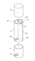
- FIG. 1 is a perspective view showing a closed state of the package according to the present embodiment.
- FIG. 2 is a perspective view showing the open state of the package according to the present embodiment.
- the package 1 has a substantially cylindrical outer shape, and includes a main body outer cylinder (also simply referred to as an “outer cylinder”) 11 and a lid 12.
- the main body outer cylinder 11 and the lid 12 each have a cylindrical shape with one end closed. That is, the main body outer cylinder 11 has a concave shape having a bottom surface in the vertical direction and an opening on the opposite side of the bottom surface, and the lid 12 has a concave shape having an upper surface in the vertical direction and an opening on the opposite side of the upper surface.
- cover 12 are connected so that each opening part may oppose in a closed state, and space is formed in an inside.
- the package 1 includes a main body inner cylinder (also simply referred to as “inner cylinder”) 13 inside the main body outer cylinder 11, and the side surface of the main body has a double structure.
- the outer shape of the main body cylinder 13 is also substantially cylindrical.
- the outer diameter of the cross section of the main body inner cylinder 13 is substantially the same as the inner diameter of the cross section of the main body outer cylinder 11 and the inner diameter of the cross section of the lid 12, but the main body outer cylinder 11 and the main body inner cylinder 13 are bonded. It has not been. Therefore, the main body outer cylinder 11 and the main body inner cylinder 13 can be relatively rotated in the circumferential direction of the cross section.
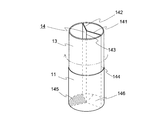
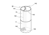
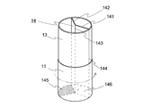
- a partition wall 14 that partitions the inside of the main body inner cylinder 13 is provided inside the main body inner cylinder 13.
- the space in the main body inner cylinder 13 is divided into two regions, the unused object 2 is stored in one region 131, and the used object (not shown) is stored in the other region 132. Is housed.
- the package 1 can change the ratio of the size of the area partitioned by the partition wall 14.
- FIG. 3 is an exploded perspective view of the package according to the present embodiment.
- FIG. 4 is an exploded perspective view for explaining the structure of the main body inner cylinder and the partition wall according to the present embodiment. 3 and 4, the two-dot chain arrow indicates the connection or bending direction of each part.
- the partition wall 14 is a partition plate extending in the vertical vertical direction, and divides the space in the main body inner cylinder 13 into two regions adjacent in the horizontal direction.
- the partition wall 14 includes an inner cylinder connection side partition wall (also referred to as “first partition wall”) 141 connected to the main body inner cylinder 13 and an outer cylinder connection side partition wall (connected to the main body outer cylinder 11).
- the inner cylinder connection side partition wall 141 and the outer cylinder connection side partition wall 142 are rotatably connected via a hinge portion 143.
- the inner cylinder connection side partition wall 141 and the outer cylinder connection side partition wall 142 have substantially the same rectangular shape, and the horizontal length is the radius of the cross section of the main body inner cylinder 13 (or the inner diameter). The length in the vertical direction is substantially the same as the height of the main body inner cylinder 13. Moreover, it arrange
- the inner cylinder connection side partition wall 141 is provided with a hinge part 143 at one end and an inner circumference connection part 144 connected to the inner circumference surface of the main body inner cylinder 13 at the other end.
- the outer cylinder connection-side partition wall 142 is also provided with a hinge portion 143 at one end, and is glued to the lower side in the vertical direction of the outer cylinder connection-side partition wall 142 by about 90 degrees and bonded to the bottom surface of the main body outer cylinder 11. It has an outer cylinder connecting portion 145 which is a substitute.
- a partition wall connection part 111 is shown on a part of the bottom surface bonded to the outer cylinder connection part 145.
- the outer cylinder connection portion 145 and the partition wall connection portion 111 are hatched.
- a bent piece 146 that is bent at about 90 degrees is also provided on the lower side in the vertical direction of the inner cylinder connection side partition wall 141.
- the bending direction of the bent piece 146 is the outer cylinder connecting portion 145 in the circumferential direction of the main body inner cylinder 13 centering on the hinge portion 143 (the axis of the main body inner cylinder 13).
- the present invention is not limited to such an example.
- the bent piece 146 may be bent in a direction facing the outer cylinder connecting portion 145 in the circumferential direction of the main body inner cylinder 13 centering on the hinge portion 143.
- the inner cylinder connection side partition wall 141 and the outer cylinder connection side partition wall 142 connected via the hinge portion 143 are connected to the main body inner cylinder 13 and the main body outer cylinder 11, respectively.
- the inner tube connection side partition wall 141 or the outer tube connection side partition wall 142 also rotates around the hinge portion 143. Furthermore, it is possible to prevent the main body inner cylinder 13 from undesirably dropping from the main body outer cylinder 11. For example, as shown by a two-dot chain line in FIG. 5A, when the main body outer cylinder 11 is fixed and the main body inner cylinder 13 is rotated clockwise as viewed from the vertical upper side, as shown in FIG.
- the main body outer cylinder 11 The position of the outer cylinder connection side partition wall 142 connected to the bottom surface of the inner cylinder does not change, and the position of the inner cylinder connection side partition wall 141 connected to the inner peripheral surface of the main body inner cylinder 13 is clockwise around the hinge portion 143. Rotate and move. 6A, when the main body inner cylinder 13 is fixed and the main body outer cylinder 11 is rotated counterclockwise as viewed from the vertical upper side, as shown in FIG. 6B, the main body inner cylinder 13 is obtained.
- the package 1 can change the ratio of the sizes of the two regions formed by dividing the interior. For example, since the other area for storing the used objects to be stored can be enlarged by the amount of reducing one area for storing the unused objects, there is no wasteful space and the efficiency is high.
- Such a package is particularly suitable for separately storing articles that do not change much in size before and after use, such as carbon heat source type smoking articles and electronic cigarette cartridges.
- it is a simple structure like the package 1, it can manufacture by assembling the blank which punched the paper material etc. with a box making machine, and while being able to hold down manufacturing cost, it is a simple structure. Assembly failure is unlikely to occur.
- FIG. 7 is an example of a blank B1 for forming the main body outer cylinder 11 or the lid 12 of the package 1.
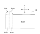
- FIG. 8 is an example of a blank B ⁇ b> 2 for forming the main body inner cylinder 13 of the package 1.
- a blank is a paper material, resin material, etc., punched into the shape of a developed view.For example, it is folded into a valley fold along a fold line indicated by a broken line, and along a fold line indicated by a one-dot chain line by a box making machine or the like. Then, the package 1 is formed by folding in a mountain fold.
- the hinge part shown with a dashed-two dotted line may make it fold a crease
- the hinge line may be perforated to make it easier to bend.
- the perforation is, for example, a line of broken or dotted holes, and the shape, number, etc. of the holes have a configuration that balances durability so as not to be separated and ease of bending.
- FIGS. 7 and 8 for convenience, the connection relationship of the regions included in the blank will be described based on the top, bottom, left, and right of the drawings.
- the blank B ⁇ b> 1 includes a substantially circular bottom region B ⁇ b> 1101 that becomes the bottom surface of the main body outer cylinder 11 or the top surface of the lid 12, and a substantially rectangular side surface area B ⁇ b> 1102 that becomes the side surface of the main body outer cylinder 11 or lid 12. Including.
- one end of the bottom area B1101 and the side area B1102 is connected in the vertical direction.
- the upper side of the side surface region B1102 is connected along the outer periphery of the bottom surface region B1101, and the left and right sides of the side surface region 1102 are connected to each other.
- the ends of each region may be connected.
- at least a part of the left end and the right end of the side surface region B1102 may be provided with a region as a margin for bonding the left and right end portions, or each end portion may be directly attached using an adhesive or an adhesive tape.
- the main body outer cylinder 11 and the lid 12 can be formed by assembling the blanks shown in FIG.
- the blank B ⁇ b> 2 includes a substantially rectangular inner cylinder area B ⁇ b> 1301 that becomes the main body inner cylinder 13 and a substantially rectangular area that becomes the partition wall 14.
- the area that becomes the partition wall 14 is provided on the left side of the inner cylinder area B1301 and connected to the inner cylinder side wall area B1411 that becomes the inner cylinder connection side partition wall 141, and on the left side of the inner cylinder side wall area 1411.
- an outer cylinder side wall region B1421 serving as the wall 142.
- a bending region B 1461 that becomes a bent piece 146 is continuously provided above the inner cylinder side wall region B 1411, and an outer cylinder connection region B 1451 that becomes an outer cylinder connection portion 145 is provided above the outer cylinder side wall region B 1421. It is connected continuously.
- the bending region B1461 and the outer cylinder connection region B1451 in FIG. 8 are each fan-shaped with a central angle of 90 degrees, but the shapes of the bending region B1461 and the outer cylinder connection region B1451 are less than 90 degrees. It does not have to be fan-shaped.
- the bent piece 146 interferes with the outer cylinder connection side partition wall 142 or the outer cylinder connection portion 145 depending on the direction of the folding, and the interference is obtained by setting the central angle of the bent piece area B1461 or the outer cylinder connection area B1451 to less than 90 degrees.
- the ratio of the space in the main body inner cylinder 13 partitioned by the partition wall 14 can be changed more greatly.
- the right end of the inner cylinder region B1301 is connected between the inner cylinder region B1301 and the inner cylinder side wall region B1411 to form an inner cylinder connection portion 144.
- an area serving as a margin may be further provided at the right end of the inner cylinder region B1301, or an adhesive or an adhesive tape may be provided. They may be used to directly bond each part.
- Blanks B1 and B2 as described above are punched along a solid line, valley-folded along a broken line, mountain-folded along a dashed-dotted line, creased in both directions along a two-dot chain line, and a predetermined region is connected Thus, the package 1 can be assembled.
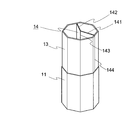
- FIG. 9 is a perspective view showing the main body outer cylinder 11, the main body inner cylinder 13, and the partition wall 14 of the package 1 according to the modification.
- the lid 12 (not shown) has substantially the same shape as the main body outer cylinder 11.
- symbol is attached
- the package 1 may have a column shape other than a cylinder.
- the main body outer cylinder 11 and the main body inner cylinder 13 shown in FIG. 9 are prisms having a regular octagonal cross section.
- the outer diameter of the cross section of the main body inner cylinder 13 and the inner diameter of the cross section of the main body outer cylinder 11 are not the same, and a play is provided between the main body inner cylinder 13 and the main body outer cylinder 11 so that they can rotate with each other. It may be possible. Further, by using a material that is easily deformed, the main body inner cylinder 13 or the main body outer cylinder 11 may be bent so as to be able to rotate with respect to each other.
- the inner cylinder connection side partition wall 141 and the outer cylinder connection side partition wall 142 connected via the hinge part 143 are connected to the main body inner cylinder 13 and the main body outer cylinder 11, respectively.
- the inner cylinder connection side partition wall 141 or the outer cylinder connection side partition wall 142 also rotates about the hinge portion 143 as an axis.
- the cross section of the main body outer cylinder 11 and the main body inner cylinder 13 has the shape which has mutually similar rotational symmetry, it is not limited to such an example.
- the unit of movement amount (the minimum value of the rotation angle) when the main body outer cylinder 11 and the main body inner cylinder 13 are relatively rotated can be adjusted by the number of corners. It is possible to adopt a unit of movement according to the contents. For example, a regular icosahedron may be adopted, but the number of corners is not particularly limited.
- FIG. 10 is a perspective view showing a main body outer cylinder 11, a main body inner cylinder 13, and a partition wall 14 of a package 1 according to another modification.
- the lid 12 (not shown) has substantially the same shape as the main body outer cylinder 11.
- FIG. 11 is an example of the blank for forming the main body inner cylinder and the partition wall according to the present modification. Also in this modified example, the same reference numerals are given to the portions corresponding to the above-described embodiments, and differences will be mainly described.
- the outer cylinder connecting portion 145 is connected to the side surface of the outer cylinder 11 instead of the bottom surface. That is, as shown in FIG. 11, the upper end of the inner cylinder side wall region B1411 is continuously provided with a bent region B1461 which becomes the first bent piece 146, and the upper end of the outer cylinder side wall region B1421 is connected with the second bent piece 147. A bent region B1471 is continuously provided. Further, an outer cylinder connection region B1451 serving as an outer cylinder connection portion 145 bonded to the inner peripheral surface or outer peripheral surface of the outer cylinder 13 is continuously provided along the arc of the fan-shaped bending region B1471. The outer cylinder connection area B1451 in FIG.
- the partition wall 14 is bent at about 90 degrees vertically below the outer tube connection side partition wall 142 and bonded to the main body outer tube 11.
- a fan-shaped bent piece 147 is continuously provided, and an outer cylinder connecting portion 145 that is further bent by about 90 degrees along the arc of the bent piece 147 and is bonded to the inner peripheral surface or the outer peripheral surface of the main body outer cylinder 11 is continuously provided. Is done.
- the outer cylinder connection-side partition wall 142 may be connected to the outer cylinder connection portion 145, and thus the main body outer cylinder 11 via another region (for example, the bent piece 147).
- the inner cylinder connecting portion 144 may have the same configuration.
- one of the partition walls 14 (for example, the inner cylinder connection side partition wall 141) is connected to the main body inner cylinder 13, and the other of the partition walls 14 (for example, the outer cylinder connection side partition wall 142) is the main body outer cylinder. 11, the ratio of the space in the package 1 partitioned by the partition wall 14 can be changed by relatively rotating the main body inner cylinder 13 and the main body outer cylinder 11.
- a hole-shaped notch is provided along the circumferential direction of the main body inner cylinder 13, and the end of the outer cylinder connection side partition wall 142 passes through the notch. And may be connected to the inner periphery of the outer cylinder 11.
- the outer diameter of the cross section of the main body inner cylinder 13 shown in FIG. 2 is substantially the same as the inner diameter of the cross section of the main body outer cylinder 11 and the inner diameter of the cross section of the lid 12.
- the outer diameter of the surface may be equal to or smaller than the inner diameter of the cross section of the main body outer cylinder 11 and the lid 12.
- the vertical heights of the partition wall 14 and the inner cylinder 13 are arbitrary, and the height of the partition wall 14 and the height of the inner cylinder 13 may be different.
- the vertical height of the partition wall 14 is in contact with the inside of the lid 12 when the lid is closed. If it does in this way, when the package 1 is inclined, it can suppress that a to-be-contained object moves between the division
- the direction in which the bent piece 146 and the outer cylinder connecting portion 145 in the embodiment or the bent piece 146 and the bent piece 147 in the second modification are bent is also arbitrary. In addition, it can suppress that a to-be-contained object moves between the division
- FIG. For example, when the outer cylinder connecting portion 145 and the bent piece 146 according to the above-described embodiment are bent in the circumferential direction of the main body outer cylinder 11 and facing each other, the outer cylinder connecting portion 145 and the bent piece 146 interfere with each other.
- the movable range of the partition wall 14 may be narrowed, a piece of ash or ash or the like moves from the region where the outer tube connecting portion 145 and the bent piece 146 are bent to the other region. This can be suppressed. The same can be said for the case where the bent piece 146 and the bent piece 147 according to the second modification described above are bent in opposite directions. However, the package 1 may not include the bent piece 146.
- FIG. 12 is an example of a blank for forming a main body inner cylinder and a partition wall according to another modification.
- the length of the inner cylinder side wall region B1411 in the vertical direction is shorter than that of the outer cylinder side wall region B1421, and the bending region B1461 includes the upper end of the inner cylinder region B1301 and the outer cylinder side wall region B1421 and the outer cylinder. It is connected to the inner cylinder side wall region B1411 below the connecting portion with the connection region B1451.
- the heights in the vertical direction of the inner cylinder connection side partition wall 141 and the outer cylinder connection side partition wall 142 are not the same, and the inner cylinder connection side partition wall 141 and the main body inner cylinder There is a gap between the bottom surface of 13.
- the bent piece 146 interferes with the outer cylinder connection-side partition wall 142 or the outer cylinder connection part 145 depending on the direction of the folding.
- the outer cylinder connection part 145 becomes the bent piece 146. You can dive down and avoid interference.
- a material having flame retardancy or heat resistance is used instead of the paper material or resin material described above, or a material having flame retardancy or heat resistance such as metal foil or glass fiber is bonded to the paper material or resin material. You may do it. If it does in this way, the safety at the time of accommodating the tobacco product in combustion in a package can be improved.
- region to which a used to-be-contained object is accommodated can be set arbitrarily.
- a region for storing a used object to be stored may have a space enough for one cigarette butt or as a ash remover.
Landscapes
- Engineering & Computer Science (AREA)
- Mechanical Engineering (AREA)
- Packaging Of Annular Or Rod-Shaped Articles, Wearing Apparel, Cassettes, Or The Like (AREA)
Abstract
簡易な構成で内部領域の比率を変更可能なパッケージを提供することを目的とする。パッケージは、底面を有する筒状の外筒と、外筒の内側に、外筒と相対的に回動可能に配設された筒状の内筒と、内筒の横断面の中心に沿った軸と平行に位置するヒンジ部を介して回動可能に接続され、内筒内の空間を区画する第1の区画壁及び第2の区画壁とを備え、第1の区画壁は内筒に接続され、第2の区画壁は外筒に接続される。
Description
本発明は、パッケージに関する。
従来、吸い殻を収容する部分を有するたばこのパッケージが提案されていた(例えば、特許文献1~3)。また、未使用の嗅ぎたばこ(snuff)を入れる領域と使用済みの嗅ぎたばこを入れる領域とを有するパッケージも提案されている(例えば、特許文献4及び5)。当該嗅ぎたばこのパッケージは円柱形状であり、中心軸の周りを回転して領域を分割する壁を有する。そして、当該壁によって各領域の比率が変更できる。
従来、領域の大きさの比率を変更可能なパッケージは提案されていた。しかしながら、例えば軸を中心に壁部分を回動させるような構成では、軸等の強度を担保するために材料が限定され、また製造コストも嵩むという問題があった。
本発明はこのような課題に鑑みてなされたものであって、簡易な構成で内部領域の比率を変更可能なパッケージを提供することを目的とする。
本発明に係るパッケージは、底面を有する筒状の外筒と、外筒の内側に、外筒と相対的に回動可能に配設された筒状の内筒と、内筒の横断面の中心に沿った軸と平行に位置するヒンジ部を介して回動可能に接続され、内筒内の空間を区画する第1の区画壁及び第2の区画壁とを備え、第1の区画壁は内筒に接続され、第2の区画壁は外筒に接続される。
なお、外筒及び内筒は円柱であっても角柱であってもよい。このようにすれば、外筒と内筒とを相対的に回動させることができ、外筒又は内筒の回動に連動して、内筒に接続された第1の区画壁又は外筒に接続された第2の区画壁を、ヒンジ部を中心に回動させることができる。したがって、第1の区画壁と第2の区画壁とのなす角度に応じて、第1の区画壁及び第2の区画壁によって区画される内筒内の空間(すなわち、容積)の比率を変更することができるようになる。
また、第2の区画壁は外筒の底面に接続されるようにしてもよい。また、第1の区画壁は内筒の内周面に接続されるようにしてもよい。例えば具体的にはこのような構成とすることで、上述のパッケージを実現することができる。例えば、第2の区画壁と外筒の底面とは糊代を介して接続することができ、第1の区画壁と内筒の内周面とは一体の部材で連続するように形成することができるため、これらの接続は容易であるといえる。
また、第1の区画壁及び第2の区画壁は形状が略同一であり、ヒンジ部は内筒の横断面の略中央に沿って位置するように設けられるようにしてもよい。このような態様とすれば、回動させる操作が容易となる。
また、上面を有し、パッケージを閉蓋可能な筒状の蓋部をさらに備えるようにしてもよい。また、第1の区画壁及び第2の区画壁の、内筒の軸方向の鉛直方向上端は、パッケージを閉蓋した状態における蓋部の上面の高さに位置するようにしてもよい。このようにすれば、パッケージを傾けた場合であっても、内部の区画された空間の間を被収容物が移動することを抑制できる。
また、第1の区画壁及び第2の区画壁は、内筒の軸方向の鉛直方向下端の位置が異なるようにしてもよい。例えば第1の区画壁が外筒の底面と接続される糊代部を有する場合、第2の区画壁の鉛直方向下端と外筒の底面との間に間隙があれば、糊代部が上述の回動を妨げることがなくなる。
また、外筒、内筒、第1の区画壁、及び第2の区画壁は、紙材料又は樹脂材料で形成されるようにしてもよい。上述したパッケージにこのような材料を採用すれば、押出成型のための特殊な製造機械は必要なく、例えば適宜設けられる糊代を貼り合わせることで容易に組み立てることができる。このため、本パッケージの構成であれば、製造コストを抑えることができる。
また、上述したパッケージは、第1の区画壁及び第2の区画壁によって区画された内筒内の空間の少なくとも一方にたばこ製品を収容するようにしてもよい。被収容物の一例として、たばこ製品を挙げることができる。未使用のたばこ製品を収容する一方の領域を小さくした分だけ、使用済みのたばこ製品を収容する他方の領域を大きくすることができるため、特に炭素熱源型の喫煙物品や電子たばこのカートリッジのように使用前後でさほど大きさの変わらない物品を分けて収容するのに好適である。
なお、上述した本発明の課題を解決するための手段の各々は、可能な限り組み合わせることができる。
本発明によれば、簡易な構成で内部領域の比率を変更可能なパッケージを提供することができる。
次に、本発明に係るパッケージの実施形態について、図面に基づいて説明する。
なお、本発明に係るパッケージに収容される被収容物は特に限定されないが、たばこ製品が好適に例示できる。たばこ製品とは、紙巻たばこ(フィルタシガレット、両切シガレット(フィルタ無し))、シガー(葉巻)、シガリロ、スヌース、嗅ぎたばこ、チューイングたばこ、炭素熱源型の喫煙物品、電子たばこ(電子たばこのカートリッジ)等を含むものとする。
また、パッケージの材料としては、カード紙、マニラボール紙、コート紙、アルミ蒸着紙等の紙材料、プラスチック等の樹脂材料、その他を用いることができる。なお、紙材料を用いる場合は、例えば坪量が100~300g/m2程度の紙が材料として好適である。
<実施形態>
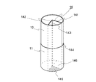
図1は、本実施形態に係るパッケージの閉蓋状態を示す斜視図である。図2は、本実施形態に係るパッケージの開蓋状態を示す斜視図である。
図1は、本実施形態に係るパッケージの閉蓋状態を示す斜視図である。図2は、本実施形態に係るパッケージの開蓋状態を示す斜視図である。
本実施形態に係るパッケージ1は、外形が略円柱形状であり、本体外筒(単に「外筒」とも呼ぶ)11と蓋12とを有する。本体外筒11及び蓋12は、それぞれ一端が塞がれた筒状になっている。すなわち、本体外筒11は、鉛直下方に底面を有するとともに底面の反対側が開口した凹状であり、蓋12は、鉛直上方に上面を有するとともに上面の反対側が開口した凹状である。そして、本体外筒11と蓋12とは、閉蓋状態においてはそれぞれの開口部が対向するように接続され、内部に空間が形成される。また、パッケージ1は、本体外筒11の内側に、本体内筒(単に「内筒」とも呼ぶ)13を備えており、本体の側面が二重構造になっている。本体内筒13の外形も略円柱形状である。また、本体内筒13の横断面の外径は、本体外筒11の横断面の内径及び蓋12の横断面の内径と略同一であるが、本体外筒11と本体内筒13とは接着されていない。よって、本体外筒11と本体内筒13とは、相対的に横断面の円周方向に回動が可能である。また、本体内筒13の内側には、本体内筒13内を区画する区画壁14を有する。本実施形態では、本体内筒13内の空間が2つの領域に区画され、一方の領域131に未使用の被収容物2が収容され、他方の領域132に使用済みの被収容物(図示せず)が収容される。また、後述する通り、パッケージ1は、区画壁14によって区画される領域の大きさの比率を変更することができる。
図3は、本実施形態に係るパッケージの分解斜視図である。また、図4は、本実施形態に係る本体内筒及び区画壁の構造を説明するための分解斜視図である。図3及び図4において、二点鎖線の矢印は、各部の接続や曲げの方向を示している。区画壁14は鉛直上下方向に延在する仕切り板であり、本体内筒13内の空間を、水平方向に隣接する2つの領域に区切る。また、区画壁14は、本体内筒13に接続される内筒接続側区画壁(「第1の区画壁」とも呼ぶ)141と、本体外筒11に接続される外筒接続側区画壁(「第2の区画壁」とも呼ぶ)142とを含み、内筒接続側区画壁141と外筒接続側区画壁142とはヒンジ部143を介して回動可能に接続されている。本実施形態では、内筒接続側区画壁141及び外筒接続側区画壁142は略同一の長方形形状であり、それぞれ、水平方向の長さは本体内筒13の横断面の半径(若しくは内径の2分の1)と略同一であり、鉛直方向の長さは本体内筒13の高さと略同一である。また、内筒の横断面の中央に沿ってヒンジ部143が位置するように配設されている。また、内筒接続側区画壁141は、一端にヒンジ部143が設けられ、他端に本体内筒13の内周面と接続される内周接続部144が設けられている。外筒接続側区画壁142も一端にヒンジ部143が設けられ、外筒接続側区画壁142の鉛直方向下側には、約90度に折り曲げられて本体外筒11の底面と貼り合わされる糊代である外筒接続部145を有する。図3の本体外筒11には、外筒接続部145と貼り合わされる底面の一部に区画壁接続部111を示している。図3及び図4において、外筒接続部145及び区画壁接続部111には、ハッチングが施されている。また、内筒接続側区画壁141の鉛直方向下側にも、約90度に折り曲げられた折り曲げ片146を有する。なお、図4に二点鎖線で示すように、折り曲げ片146を折り曲げる方向は、ヒンジ部143(本体内筒13の軸)を中心とする本体内筒13の周方向のうち外筒接続部145を折り曲げる方向と同一の方向になっているが、このような例には限定されない。例えば、図4に一点鎖線で示すように、折り曲げ片146は、ヒンジ部143を中心とする本体内筒13の周方向のうち外筒接続部145と対向する方向に折り曲げるようにしてもよい。
<作用及び効果>
ヒンジ部143を介して接続された内筒接続側区画壁141及び外筒接続側区画壁142が、それぞれ本体内筒13及び本体外筒11に接続されているため、本体外筒11と本体内筒13とを相対的に回動させることにより、内筒接続側区画壁141又は外筒接続側区画壁142もヒンジ部143を軸として回動する。さらに本体内筒13が本体外筒11から不所望に脱落することを抑制することもできる。例えば、図5Aに二点鎖線で示すように、本体外筒11を固定して本体内筒13を鉛直上側から見て右回りに回動させると、図5Bに示すように、本体外筒11の底面に接続された外筒接続側区画壁142の位置は変わらず、本体内筒13の内周面に接続された内筒接続側区画壁141の位置はヒンジ部143を中心に右回りに回転移動する。また、図6Aに二点鎖線で示すように、本体内筒13を固定して本体外筒11を鉛直上側から見て左回りに回動させると、図6Bに示すように、本体内筒13の内周面に接続された内筒接続側区画壁141の位置は変わらず、本体外筒11の底面に接続された外筒接続側区画壁142の位置はヒンジ部143を中心に左回りに回転移動する。このように、パッケージ1は、内部を分割して形成された2つの領域の大きさの比率を変更することができる。例えば未使用の被収容物を収容する一方の領域を小さくした分だけ、使用済みの被収容物を収容する他方の領域を大きくすることができるため、無駄な空間がなく効率がよい。このようなパッケージは、特に炭素熱源型の喫煙物品や電子たばこのカートリッジのように、使用前後でさほど大きさの変わらない物品を分けて収容するのに好適である。また、パッケージ1のように簡易な構成であれば、紙材料等を打ち抜いたブランクを製函機で組み立てることにより製造することができ、製造コストを抑えることができるとともに、簡易な構成であるため組立不良も発生し難い。
ヒンジ部143を介して接続された内筒接続側区画壁141及び外筒接続側区画壁142が、それぞれ本体内筒13及び本体外筒11に接続されているため、本体外筒11と本体内筒13とを相対的に回動させることにより、内筒接続側区画壁141又は外筒接続側区画壁142もヒンジ部143を軸として回動する。さらに本体内筒13が本体外筒11から不所望に脱落することを抑制することもできる。例えば、図5Aに二点鎖線で示すように、本体外筒11を固定して本体内筒13を鉛直上側から見て右回りに回動させると、図5Bに示すように、本体外筒11の底面に接続された外筒接続側区画壁142の位置は変わらず、本体内筒13の内周面に接続された内筒接続側区画壁141の位置はヒンジ部143を中心に右回りに回転移動する。また、図6Aに二点鎖線で示すように、本体内筒13を固定して本体外筒11を鉛直上側から見て左回りに回動させると、図6Bに示すように、本体内筒13の内周面に接続された内筒接続側区画壁141の位置は変わらず、本体外筒11の底面に接続された外筒接続側区画壁142の位置はヒンジ部143を中心に左回りに回転移動する。このように、パッケージ1は、内部を分割して形成された2つの領域の大きさの比率を変更することができる。例えば未使用の被収容物を収容する一方の領域を小さくした分だけ、使用済みの被収容物を収容する他方の領域を大きくすることができるため、無駄な空間がなく効率がよい。このようなパッケージは、特に炭素熱源型の喫煙物品や電子たばこのカートリッジのように、使用前後でさほど大きさの変わらない物品を分けて収容するのに好適である。また、パッケージ1のように簡易な構成であれば、紙材料等を打ち抜いたブランクを製函機で組み立てることにより製造することができ、製造コストを抑えることができるとともに、簡易な構成であるため組立不良も発生し難い。
<製造方法>
図7は、パッケージ1の本体外筒11又は蓋12を形成するためのブランクB1の一例である。図8は、パッケージ1の本体内筒13を形成するためのブランクB2の一例である。ブランクとは、紙材料、樹脂材料等を展開図の形状に打ち抜いたものであり、例えば製函機等により、破線で示す折込み線に沿って谷折りに折り、一点鎖線で示す折り込み線に沿って山折りに折ることで、パッケージ1が形成される。なお、二点鎖線で示すヒンジ部は、山折り及び谷折りの両方向に折り癖をつけるようにしてもよいし、いずれか一方に折るようにしてもよい。また、ヒンジ線はミシン目にすることで折り曲げをさらに容易にするようにしてもよい。なお、ミシン目は、例えば破線状又は点線状の孔の列であり、孔の形状、数等は、切り離されない程度の耐久性と折り曲げ易さとのバランスをとった構成とする。以下では、図7及び図8に方向を示した通り、便宜上、図面の上下左右に基づいてブランクに含まれる領域の接続関係を説明する。
図7は、パッケージ1の本体外筒11又は蓋12を形成するためのブランクB1の一例である。図8は、パッケージ1の本体内筒13を形成するためのブランクB2の一例である。ブランクとは、紙材料、樹脂材料等を展開図の形状に打ち抜いたものであり、例えば製函機等により、破線で示す折込み線に沿って谷折りに折り、一点鎖線で示す折り込み線に沿って山折りに折ることで、パッケージ1が形成される。なお、二点鎖線で示すヒンジ部は、山折り及び谷折りの両方向に折り癖をつけるようにしてもよいし、いずれか一方に折るようにしてもよい。また、ヒンジ線はミシン目にすることで折り曲げをさらに容易にするようにしてもよい。なお、ミシン目は、例えば破線状又は点線状の孔の列であり、孔の形状、数等は、切り離されない程度の耐久性と折り曲げ易さとのバランスをとった構成とする。以下では、図7及び図8に方向を示した通り、便宜上、図面の上下左右に基づいてブランクに含まれる領域の接続関係を説明する。
図7に示すように、ブランクB1は、本体外筒11の底面又は蓋12の上面となる略円形の底面領域B1101と、本体外筒11又は蓋12の側面となる略長方形形状の側面領域B1102とを含む。図7の例では、底面領域B1101及び側面領域B1102は上下方向に一端が接続されている。また、パッケージを組み立てる際には、底面領域B1101の外周に沿って側面領域B1102の上側の辺が接続されると共に、側面領域1102の左右の辺が互いに接続される。なお、底面領域B1101の外周及び側面領域1102の上端の少なくとも一部に、各領域を接着する糊代となる領域を設けるようにしてもよいし、接着剤又は粘着テープ等、他の部材を用いて各領域の端部を接続するようにしてもよい。また、側面領域B1102の左端及び右端の少なくとも一部に、左右の端部を接着する糊代となる領域を設けるようにしてもよいし、接着剤又は粘着テープ等を用いて各端部を直接接着するようにしてもよい。本体外筒11及び蓋12は、それぞれ図7に示したブランクを組み立てることにより形成することができる。なお、本体外筒11と蓋12とは高さが異なっていてもよく、側面領域B1102の上下方向の長さは本体外筒11及び蓋12の高さに合わせて変更することができる。
また、図8に示すように、ブランクB2は、本体内筒13となる略長方形の内筒領域B1301と、区画壁14となる略長方形の領域とを含む。区画壁14となる領域は、内筒領域B1301の左側に連設され内筒接続側区画壁141となる内筒側壁領域B1411と、内筒側壁領域1411の左側に連設され外筒接続側区画壁142となる外筒側壁領域B1421とを含む。また、内筒側壁領域B1411の上側には、折り曲げ片146となる折り曲げ領域B1461が連設されており、外筒側壁領域B1421の上側には、外筒接続部145となる外筒接続領域B1451が連設されている。なお、図8の折り曲げ領域B1461及び外筒接続領域B1451は、それぞれ中心角が90度の扇形であるが、折り曲げ領域B1461及び外筒接続領域B1451の形状は中心角が90度未満であってもよく、また扇形でなくてもよい。折り曲げ片146は、その折返しの方向によって外筒接続側区画壁142又は外筒接続部145と干渉するところ、折り曲げ片領域B1461又は外筒接続領域B1451の中心角を90度未満にすることで干渉を低減することができ、区画壁14によって仕切られる本体内筒13内の空間の比率をより大きく変更することができるようになる。なお、内筒領域B1301の右側の端部は、内筒領域B1301と内筒側壁領域B1411との間に接続され、内筒接続部144が形成される。図8の例は外筒接続領域B1451以外の糊代を示していないが、例えば内筒領域B1301の右端に糊代となる領域をさらに設けるようにしてもよいし、接着剤又は粘着テープ等を用いて各部を直接接着するようにしてもよい。
以上のようなブランクB1及びB2を実線に沿って打ち抜き、破線に沿って谷折りとし、一点鎖線に沿って山折りとし、二点鎖線に沿って両方向に折り目を付け、所定の領域を接続することで、パッケージ1を組み立てることができる。
<変形例1>
図9は、変形例に係るパッケージ1の本体外筒11、本体内筒13、及び区画壁14を示す斜視図である。なお、蓋12(図示せず)は、本体外筒11と略同一の形状とする。変形例においては、上述した実施形態と対応する箇所に同一の符号を付し、相違点を中心に説明する。
図9は、変形例に係るパッケージ1の本体外筒11、本体内筒13、及び区画壁14を示す斜視図である。なお、蓋12(図示せず)は、本体外筒11と略同一の形状とする。変形例においては、上述した実施形態と対応する箇所に同一の符号を付し、相違点を中心に説明する。
図9に示すように、パッケージ1は、円柱以外の柱状であってもよい。図9に示す本体外筒11及び本体内筒13は、横断面の形状が正八角形の角柱である。この場合、本体内筒13の横断面の外径と本体外筒11の横断面の内径とを同一とせず、本体内筒13と本体外筒11との間に遊びを設けて互いに回動が可能となるようにしてもよい。また、変形し易い素材を用いることで、本体内筒13又は本体外筒11を撓ませて互いに回動が可能となるようにしてもよい。図9に示す区画壁14も、ヒンジ部143を介して接続された内筒接続側区画壁141及び外筒接続側区画壁142が、それぞれ本体内筒13及び本体外筒11に接続されており、本体外筒11と本体内筒13とを相対的に回動させることにより、内筒接続側区画壁141又は外筒接続側区画壁142もヒンジ部143を軸として回動する。なお、本体外筒11及び本体内筒13の横断面は、互いに相似な回転対称性を有する形状が好ましいといえるが、このような例には限定されない。また、本体外筒11及び本体内筒13の横断面は、多角形の場合、角が多いほどスムーズな回転が期待できる。また、多角形の場合、角の数によって本体外筒11と本体内筒13とを相対的に回動させる際の移動量の単位(回転角の最小値)を調整することができ、例えば被収容物に応じて移動量の単位を採用することが可能となる。例えば正二十角形等を採用し得るが、角の数は特に限定されない。
<変形例2>
図10は、他の変形例に係るパッケージ1の本体外筒11、本体内筒13、及び区画壁14を示す斜視図である。なお、蓋12(図示せず)は、本体外筒11と略同一の形状とする。また、図11は、本変形例に係る本体内筒及び区画壁を形成するためのブランクの一例である。本変形例においても、上述した実施形態と対応する箇所に同一の符号を付し、相違点を中心に説明する。
図10は、他の変形例に係るパッケージ1の本体外筒11、本体内筒13、及び区画壁14を示す斜視図である。なお、蓋12(図示せず)は、本体外筒11と略同一の形状とする。また、図11は、本変形例に係る本体内筒及び区画壁を形成するためのブランクの一例である。本変形例においても、上述した実施形態と対応する箇所に同一の符号を付し、相違点を中心に説明する。
図10の例では、外筒接続部145が外筒11の底面でなく側面と接続されている。すなわち、図11に示すように、内筒側壁領域B1411の上端には第1の折り曲げ片146となる折り曲げ領域B1461が連設され、外筒側壁領域B1421の上端には第2の折り曲げ片147となる折り曲げ領域B1471が連設されている。さらに、扇形である折り曲げ領域B1471の円弧に沿って、外筒13の内周面又は外周面と接着される外筒接続部145となる外筒接続領域B1451が連設されている。なお、図11の外筒接続領域B1451は、折り曲げ領域B1471の円弧に沿って折り曲げられるよう3つの領域に分けられているが、外筒接続領域B1451の形状及び大きさは、図11の例には限定されない。図11のブランクを組み立てることにより、図10に示すように、区画壁14のうち外筒接続側区画壁142の鉛直下方には、約90度に折り曲げられ、本体外筒11とは接着されていない扇形の折り曲げ片147が連設され、折り曲げ片147の円弧に沿って、さらに約90度に折り曲げられ本体外筒11の内周面又は外周面と接着される外筒接続部145が連設される。
このように、外筒接続側区画壁142は、他の領域(例えば折り曲げ片147)を介して外筒接続部145、ひいては本体外筒11と接続されていてもよい。また、内筒接続部144についても、同様の構成としてもよい。本変形例のように、区画壁14の一方(例えば内筒接続側区画壁141)が本体内筒13と接続され、区画壁14の他方(例えば外筒接続側区画壁142)が本体外筒11と接続されていれば、本体内筒13及び本体外筒11を相対的に回動させることにより区画壁14が仕切るパッケージ1内の空間の比率を変更することができる。なお、図10及び図11に示した態様のほか、例えば、本体内筒13の周方向に沿って穴状の切り欠きを設け、外筒接続側区画壁142の端部が切り欠きを通過して外筒11の内周と接続されていてもよい。
<その他の変形>
上述した実施形態及び変形例は例示であり、本発明に係るパッケージは図示した構成には限定されない。例えばパッケージの大きさ、各部の大きさの比率、これらに基づくパッケージに収容することができる被収容物の数等は変更することができる。
上述した実施形態及び変形例は例示であり、本発明に係るパッケージは図示した構成には限定されない。例えばパッケージの大きさ、各部の大きさの比率、これらに基づくパッケージに収容することができる被収容物の数等は変更することができる。
例えば、図2等に示した本体内筒13の横断面の外径は、本体外筒11の横断面の内径及び蓋12の横断面の内径と略同一であるが、本体内筒13の横断面の外径は、本体外筒11及び蓋12の横断面の内径以下であればよい。
また、区画壁14及び内筒13の鉛直方向の高さは任意であり、区画壁14の高さと内筒13の高さとが異なっていてもよい。ここで、区画壁14の鉛直方向の高さは、閉蓋時において蓋12の内側と接する程度が好ましい。このようにすれば、パッケージ1を傾けた場合に内部の区画された領域間を被収容物が移動することを抑制できる。
また、実施形態における折り曲げ片146及び外筒接続部145、又は変形例2における折り曲げ片146及び折り曲げ片147を折り曲げる方向も任意である。なお、折り曲げ片146や折り曲げ片147によっても、区画された領域間を被収容物が移動することを抑制することができる。例えば、上述した実施形態に係る外筒接続部145と折り曲げ片146とを、本体外筒11の周方向であって対向する方向に折り曲げた場合、外筒接続部145と折り曲げ片146とが干渉して区画壁14の可動範囲が狭くなるおそれがある反面、外筒接続部145と折り曲げ片146とが折り曲げられた方向の領域から他方の領域へ、被収容物のかけらや灰等が移動することを抑制できる。上述した変形例2に係る折り曲げ片146と折り曲げ片147とを対向する方向に折り曲げる場合についても、同じことがいえる。ただし、パッケージ1は、折り曲げ片146を備えていなくてもよい。
図12は、他の変形例に係る本体内筒及び区画壁を形成するためのブランクの一例である。図12の例は、内筒側壁領域B1411の上下方向の長さが外筒側壁領域B1421よりも短くなっており、折り曲げ領域B1461は、内筒領域B1301の上端や外筒側壁領域B1421と外筒接続領域B1451との接続部よりも下方で内筒側壁領域B1411と接続されている。このようなブランクを用いてパッケージを組み立てると、内筒接続側区画壁141と外筒接続側区画壁142との鉛直方向の高さは同一でなくなり、内筒接続側区画壁141と本体内筒13の底面との間には間隙が生じる。上述の通り、折り曲げ片146は、その折返しの方向によって外筒接続側区画壁142又は外筒接続部145と干渉するところ、図12のブランクを用いれば、外筒接続部145が折り曲げ片146の下に潜り込み、干渉を避けることができるようになる。
また、上述した紙材料又は樹脂材料の代わりに難燃性又は耐熱性を有する材料を用いたり、紙材料又は樹脂材料に金属箔やガラス繊維等、難燃性又は耐熱性を有する材料を貼り合わせるようにしてもよい。このようにすれば、燃焼中のたばこ製品をパッケージ内に収容する場合の安全性を向上させることができる。
また、何らかの製品等を収容する場合、未使用の被収容物を収容する領域と使用済みの被収容物を収容する領域との比率は、任意に設定できる。たばこ製品を収容するような場合、開封直後において、使用済みの被収容物を収容する領域が吸い殻1本分程度、又は灰落としとして使用可能な程度の空隙を有するようにしてもよい。
1 パッケージ
11 本体外筒
12 蓋
13 本体内筒
14 区画壁
141 内筒接続側区画壁
142 外筒接続側区画壁
143 ヒンジ部
144 内筒接続部
145 外筒接続部
146 折り曲げ片
147 折り曲げ片
2 被収容物
11 本体外筒
12 蓋
13 本体内筒
14 区画壁
141 内筒接続側区画壁
142 外筒接続側区画壁
143 ヒンジ部
144 内筒接続部
145 外筒接続部
146 折り曲げ片
147 折り曲げ片
2 被収容物
Claims (9)
- 底面を有する筒状の外筒と、
前記外筒の内側に、前記外筒と相対的に回動可能に配設された筒状の内筒と、
前記内筒の横断面の中心に沿った軸と平行に位置するヒンジ部を介して回動可能に接続され、前記内筒内の空間を区画する第1の区画壁及び第2の区画壁と、
を備え、
前記第1の区画壁は前記内筒に接続され、前記第2の区画壁は前記外筒に接続された
パッケージ。 - 前記第1の区画壁は前記内筒の内周面に接続される請求項1に記載のパッケージ。
- 前記第2の区画壁は前記外筒の底面に接続される請求項1又は2に記載のパッケージ。
- 前記第1の区画壁及び前記第2の区画壁は形状が略同一であり、前記ヒンジ部は前記内筒の横断面の略中央に沿って位置するように設けられる請求項1から3のいずれか一項に記載のパッケージ。
- 上面を有し、前記パッケージを閉蓋可能な筒状の蓋部をさらに備える請求項1から4のいずれか一項に記載のパッケージ。
- 前記第1の区画壁及び前記第2の区画壁の、前記内筒の軸方向の鉛直方向上端は、前記パッケージを閉蓋した状態における前記蓋部の上面の高さに位置する
請求項5に記載のパッケージ。 - 前記第1の区画壁及び前記第2の区画壁は、前記内筒の軸方向の鉛直方向下端の位置が異なる請求項1から6のいずれか一項に記載のパッケージ。
- 前記外筒、前記内筒、前記第1の区画壁、及び前記第2の区画壁は、紙材料又は樹脂材料で形成される請求項1から7のいずれか一項に記載のパッケージ。
- 前記第1の区画壁及び前記第2の区画壁によって区画された前記内筒内の空間の少なくとも一方にたばこ製品を収容する請求項1から8のいずれか一項に記載のパッケージ。
Priority Applications (1)
| Application Number | Priority Date | Filing Date | Title |
|---|---|---|---|
| PCT/JP2014/083979 WO2016103333A1 (ja) | 2014-12-22 | 2014-12-22 | パッケージ |
Applications Claiming Priority (1)
| Application Number | Priority Date | Filing Date | Title |
|---|---|---|---|
| PCT/JP2014/083979 WO2016103333A1 (ja) | 2014-12-22 | 2014-12-22 | パッケージ |
Publications (1)
| Publication Number | Publication Date |
|---|---|
| WO2016103333A1 true WO2016103333A1 (ja) | 2016-06-30 |
Family
ID=56149435
Family Applications (1)
| Application Number | Title | Priority Date | Filing Date |
|---|---|---|---|
| PCT/JP2014/083979 Ceased WO2016103333A1 (ja) | 2014-12-22 | 2014-12-22 | パッケージ |
Country Status (1)
| Country | Link |
|---|---|
| WO (1) | WO2016103333A1 (ja) |
Citations (6)
| Publication number | Priority date | Publication date | Assignee | Title |
|---|---|---|---|---|
| JPS4935362Y1 (ja) * | 1970-09-01 | 1974-09-26 | ||
| JP2001192073A (ja) * | 1999-12-28 | 2001-07-17 | Yoshino Kogyosho Co Ltd | 錠剤ケース |
| JP3138492U (ja) * | 2007-10-22 | 2008-01-10 | アイパックスイケタニ株式会社 | 容器 |
| JP2008013178A (ja) * | 2006-06-30 | 2008-01-24 | Yoshino Kogyosho Co Ltd | 錠剤ケース |
| US20100065077A1 (en) * | 2006-11-28 | 2010-03-18 | Caroline Lofgreen-Ohrn | Snuff box |
| US20100101186A1 (en) * | 2008-10-28 | 2010-04-29 | J.L. Clark, Inc. | Container With Compactor |
-
2014
- 2014-12-22 WO PCT/JP2014/083979 patent/WO2016103333A1/ja not_active Ceased
Patent Citations (6)
| Publication number | Priority date | Publication date | Assignee | Title |
|---|---|---|---|---|
| JPS4935362Y1 (ja) * | 1970-09-01 | 1974-09-26 | ||
| JP2001192073A (ja) * | 1999-12-28 | 2001-07-17 | Yoshino Kogyosho Co Ltd | 錠剤ケース |
| JP2008013178A (ja) * | 2006-06-30 | 2008-01-24 | Yoshino Kogyosho Co Ltd | 錠剤ケース |
| US20100065077A1 (en) * | 2006-11-28 | 2010-03-18 | Caroline Lofgreen-Ohrn | Snuff box |
| JP3138492U (ja) * | 2007-10-22 | 2008-01-10 | アイパックスイケタニ株式会社 | 容器 |
| US20100101186A1 (en) * | 2008-10-28 | 2010-04-29 | J.L. Clark, Inc. | Container With Compactor |
Similar Documents
| Publication | Publication Date | Title |
|---|---|---|
| JP5778272B2 (ja) | 対称に位置する側部キャビティーを含む紙巻きタバコパック | |
| JP5666022B2 (ja) | 喫煙品用パッケージ | |
| JP5313678B2 (ja) | 小群のたばこ製品のためのパッケージ | |
| CN102083710A (zh) | 包装盒以及相应的盒坯 | |
| JP2018508427A (ja) | 切り抜きを含むスペーサーを備えた消費者物品用の容器 | |
| RU2573963C1 (ru) | Упаковка коробчатого типа | |
| JP6228197B2 (ja) | タバコ製品用のパケット | |
| JP2006290468A (ja) | 硬質な蝶番のある蓋付き包装箱を製造するためのタバコ包装機 | |
| RU2580504C2 (ru) | Упаковочная емкость | |
| CN103946128B (zh) | 具有铰接盖的容器 | |
| JP2016513052A (ja) | パック | |
| JP6078653B2 (ja) | スライドパッケージ | |
| EP3099586B1 (en) | A rigid packet with hinged lid and containing a group of smoking articles of reduced size | |
| CN107074433A (zh) | 吸烟制品的包装 | |
| JP6689820B2 (ja) | たばこ用パッケージ | |
| CA1081179A (en) | Packets for cigarettes, cigarillos or the like | |
| RU2625899C2 (ru) | Коробка для табачной промышленности | |
| EP3099583B1 (en) | A rigid packet with hinged lid and containing a group of smoking articles of reduced size | |
| JP6909210B2 (ja) | 内側パッケージを備えた容器 | |
| WO2015015399A1 (en) | Packet for smoker's articles, in particular cigarettes. | |
| CN102083709B (zh) | 包装盒及相应的盒坯 | |
| JP2014005027A (ja) | 包装容器 | |
| TW201622588A (zh) | 包裝 | |
| JP6702934B2 (ja) | 深さのある内側フレームを備えた消費者物品用の容器 | |
| WO2016189624A1 (ja) | 棒状たばこ物品用パッケージ |
Legal Events
| Date | Code | Title | Description |
|---|---|---|---|
| 121 | Ep: the epo has been informed by wipo that ep was designated in this application |
Ref document number: 14908941 Country of ref document: EP Kind code of ref document: A1 |
|
| NENP | Non-entry into the national phase |
Ref country code: DE |
|
| 122 | Ep: pct application non-entry in european phase |
Ref document number: 14908941 Country of ref document: EP Kind code of ref document: A1 |
|
| NENP | Non-entry into the national phase |
Ref country code: JP |