WO2016098756A1 - Printed matter - Google Patents
Printed matter Download PDFInfo
- Publication number
- WO2016098756A1 WO2016098756A1 PCT/JP2015/085016 JP2015085016W WO2016098756A1 WO 2016098756 A1 WO2016098756 A1 WO 2016098756A1 JP 2015085016 W JP2015085016 W JP 2015085016W WO 2016098756 A1 WO2016098756 A1 WO 2016098756A1
- Authority
- WO
- WIPO (PCT)
- Prior art keywords
- layer
- light
- printed matter
- light control
- laminated
- Prior art date
Links
Images


Classifications
-
- B—PERFORMING OPERATIONS; TRANSPORTING
- B41—PRINTING; LINING MACHINES; TYPEWRITERS; STAMPS
- B41J—TYPEWRITERS; SELECTIVE PRINTING MECHANISMS, i.e. MECHANISMS PRINTING OTHERWISE THAN FROM A FORME; CORRECTION OF TYPOGRAPHICAL ERRORS
- B41J2/00—Typewriters or selective printing mechanisms characterised by the printing or marking process for which they are designed
- B41J2/005—Typewriters or selective printing mechanisms characterised by the printing or marking process for which they are designed characterised by bringing liquid or particles selectively into contact with a printing material
- B41J2/01—Ink jet
-
- B—PERFORMING OPERATIONS; TRANSPORTING
- B41—PRINTING; LINING MACHINES; TYPEWRITERS; STAMPS
- B41M—PRINTING, DUPLICATING, MARKING, OR COPYING PROCESSES; COLOUR PRINTING
- B41M3/00—Printing processes to produce particular kinds of printed work, e.g. patterns
- B41M3/06—Veined printings; Fluorescent printings; Stereoscopic images; Imitated patterns, e.g. tissues, textiles
-
- B—PERFORMING OPERATIONS; TRANSPORTING
- B41—PRINTING; LINING MACHINES; TYPEWRITERS; STAMPS
- B41M—PRINTING, DUPLICATING, MARKING, OR COPYING PROCESSES; COLOUR PRINTING
- B41M5/00—Duplicating or marking methods; Sheet materials for use therein
-
- B—PERFORMING OPERATIONS; TRANSPORTING
- B41—PRINTING; LINING MACHINES; TYPEWRITERS; STAMPS
- B41M—PRINTING, DUPLICATING, MARKING, OR COPYING PROCESSES; COLOUR PRINTING
- B41M5/00—Duplicating or marking methods; Sheet materials for use therein
- B41M5/50—Recording sheets characterised by the coating used to improve ink, dye or pigment receptivity, e.g. for ink-jet or thermal dye transfer recording
- B41M5/52—Macromolecular coatings
-
- G—PHYSICS
- G09—EDUCATION; CRYPTOGRAPHY; DISPLAY; ADVERTISING; SEALS
- G09F—DISPLAYING; ADVERTISING; SIGNS; LABELS OR NAME-PLATES; SEALS
- G09F13/00—Illuminated signs; Luminous advertising
- G09F13/04—Signs, boards or panels, illuminated from behind the insignia
Definitions
- the present invention relates to a printed matter, and more particularly to a technique related to improvement of image quality in three-dimensional printing.
- Patent Documents 1 to 5 Various printed materials have been developed so that printed images can be perceived in three dimensions (Patent Documents 1 to 5).
- a lenticular lens is formed on an image printed on a medium (Patent Document 1), or an unevenness is formed by a clear layer made of a transparent resin, and an image formed on or below it is perceived three-dimensionally.
- Patent Documents 2 and 3 There are those that can be made.
- a white reflective layer is partially provided on the medium, and an image is printed on the medium so that a three-dimensional perception can be made due to the difference in visual effect between the portion where the white reflective layer is provided and the portion where the white reflective layer is not provided.
- the present invention has been made to solve such problems, and obtains high image quality in both cases where an image is perceived by transmitted light and an image is perceived by reflected light.
- the purpose is to provide a printed material that can be printed.
- the printed matter according to one embodiment of the present invention includes a substrate, a laminated clear layer, and a light control layer.
- the substrate has optical transparency.
- the laminated clear layer is formed by laminating a plurality of light-transmitting clear element layers, and is disposed above one main surface (one main surface) of the substrate.
- the light control layer has a function of adjusting the amount of transmitted light, and is disposed above the laminated clear layer and at least one of the layers of a plurality of laminated clear layers.
- the light control layer in this embodiment has a plurality of light reflective particles and is provided so as to cover a part of the surface of the layer serving as the base.
- Each of the plurality of light reflective particles is granular, and the surface has light reflectivity.
- the light control layer covers an area ratio of 2% to 50% with respect to the surface of the underlying layer in plan view.
- high image quality can be realized both in the case where an image is perceived by transmitted light and the case where an image is perceived by reflected light.
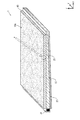
- FIG. 1 is a schematic perspective view showing an external appearance of a lighting device 1 according to Embodiment 1.
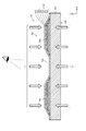
- FIG. It is a schematic cross section which shows the structure of the printed matter 10 with which the illuminating device 1 is provided.
- (A) is a schematic diagram which shows about the progress of the light which injected from the back surface 10b with respect to the printed matter 10,
- (b) shows about the progress of the light which entered from the back surface 90b with respect to the printed matter 90 which concerns on the comparative example 1.
- (c) is a schematic diagram showing the progress of light incident from the front surface 91a with respect to the printed matter 91 according to Comparative Example 2.
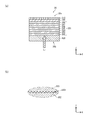
- FIG. 1 is a schematic cross-sectional view showing the configuration of the printed material 10
- (b) is a schematic plan view showing a part of the light control layer 107 and the color layer 106 that is the base
- (c) is a schematic plan view of the light control layer 107 and the color layer 106 viewed in plan. It is a schematic diagram which shows the usage example of the illuminating device 1.
- FIG. FIG. 3 is a process diagram illustrating an outline of a method for producing a printed material 10.
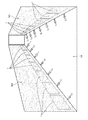
- 6 is a schematic cross-sectional view illustrating a configuration of a printed material 30 according to Embodiment 2.
- FIG. 10 is a schematic cross-sectional view illustrating a configuration of a printed material 60 according to a fifth embodiment.
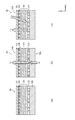
- FIG. (A) is a schematic cross section which shows the structure of the printed matter 70 concerning Embodiment 6
- (b) is a schematic cross section which shows the structure of the printed matter 80 concerning Embodiment 7.
- FIG. (A) is a cross-sectional image in the longitudinal section about the state which irradiated the light from the back surface with respect to the printed matter 70
- (b) is the longitudinal section about the state which irradiated the light from the back surface with respect to the printed matter 80
- (C) is a cross-sectional image in a cross section in a state where light is irradiated from the back surface to the printed material 70, and (d) is light irradiated from the back surface to the printed material 80.
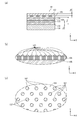
- (A) is an image taken from directly above the state in which light is irradiated from the back surface to the printed material 70, and (b) is photographed from directly above in a state where light is irradiated from the back surface to the printed material 80.
- (C) is an image taken obliquely from above with respect to a state in which the printed material 70 is irradiated with light from the back surface, and (d) is oblique with respect to a state in which the printed material 80 is irradiated with light from the back surface. It is an image taken from above.
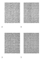
- (A) to (o) are diagrams showing light transmission states when the concentration of the light control layer is changed in a range of 2% to 30%.
- (A) to (g) are diagrams showing light transmission states when the concentration of the light control layer is changed in the range of 40% to 100%.
- the printed matter according to one aspect of the present invention includes a substrate, a laminated clear layer, and a light control layer.
- the substrate has optical transparency.
- the laminated clear layer is formed by laminating a plurality of light-transmitting clear element layers, and is disposed above one main surface (one main surface) of the substrate.
- “arranged upward” means both the case where it is disposed directly on the underlying layer and the case where it is disposed on the underlying layer via another layer. including.
- the light control layer has a function of adjusting the amount of transmitted light, and is disposed above the laminated clear layer and at least one of the layers of a plurality of laminated clear layers.
- the light control layer in this embodiment has a plurality of light reflective particles and is provided so as to cover a part of the surface of the layer serving as the base.
- Each of the plurality of light reflective particles is granular, and the surface has light reflectivity.
- the light control layer covers an area ratio of 2% to 50% with respect to the surface of the underlying layer in plan view.
- the light control layer covers the surface of the underlying layer with an area ratio of 2% to 50% (may be described as “2% to 50% density”). Therefore, high image quality can be realized both in the case where the image is perceived by the transmitted light and the case where the image is perceived by the reflected light.
- the light control layer when adopting an aspect in which the light control layer is disposed above the laminated clear layer, for example, high image quality such as emphasizing black (darkness) or a sense of depth is obtained. It also has an effect on the top.
- the light control layer is provided in a dot pattern in the above configuration. Even when such a configuration is adopted, high image quality can be realized both in the case where an image is perceived by transmitted light and the case where an image is perceived by reflected light.
- the “halftone dot” means that a layer is formed with a small dot pattern (dot pattern) on the surface of the base in printing, and includes a case where adjacent dots are connected.
- the printed matter according to one embodiment of the present invention may be configured to further include a color layer in the above configuration.
- the color layer is formed in a direction along one principal surface of the substrate with one color or a plurality of colors, and is disposed above the one principal surface of the substrate.
- the configuration including the color layer it is possible to make the viewer perceive an image rich in expressive power.
- the light control layer it is possible to realize excellent color reproducibility, particularly when perceived by transmitted light.
- the color layer is disposed so as to cover the top surface of the laminated clear layer
- the light control layer is It arrange
- the light control layer so as to cover a part of the laminated clear layer and the color layer, light is incident on the back surface (the other main surface) of the substrate and the laminated clear layer is transmitted. Even in this case, it is possible to prevent the light from being colored (for example, yellow turbidity).
- the first aspect it is possible to reproduce a transparent image by adding a clear layer having a thinner thickness on the light control layer.
- the printed matter according to one aspect of the present invention includes the second light control layer in the above configuration.
- a 2nd light control layer is arrange
- the second light control layer also has a plurality of light-reflective particles each having a light-reflective property on each surface and each having a granular shape.
- the second light control layer is provided so as to cover an area ratio of 2% to 50% with respect to the surface of the underlying layer in plan view.
- the region in which the transmitted light is to be completely blocked can be dealt with by forming a reflective layer (white layer) with a concentration of 100%, for example.
- the second light control layer when the second light control layer is disposed between one main surface of the substrate and the laminated clear layer, when the viewer perceives an image by reflected light, The portion is reflected by the second light control layer. For this reason, the light quantity ratio of the reflected light with respect to the light incident from above can be increased.
- the ratio (density) at which the surface of the base layer is covered with the second light control layer is the ratio at which the light control layer covers the surface of the base layer ( Higher than (concentration).
- the light control layer is disposed so as to cover each part of the upper surface and the side surface of the laminated clear layer.
- the color layer is arranged so as to cover the upper surface of the light control layer.
- the color layer is a stacked body in which a plurality of color element layers are stacked.
- the texture of the image can be enhanced by providing the color layer with a multilayer structure.
- the printed matter according to one embodiment of the present invention further includes a protective layer in the above configuration.
- the protective layer has light transmittance and is disposed so as to cover the upper surface of the laminated structure (the protective layer is disposed on the uppermost surface of the printed material).
- the protective layer is arranged on the upper surface of the laminated structure, when a viewer who perceives the image touches the surface of the printed matter by performing pseudo embossing by arranging the laminated clear layer Even in this case, the layer disposed under the protective layer such as the light control layer or the clear element layer can be protected.
- the aspect provided with a color layer it becomes possible to prevent fading of a color layer etc. by selecting the kind of protective layer.
- the protective layer is matted in the above configuration.
- it can be realized by forming irregularities on the surface.
- the texture of an image can be changed with the area
- the second laminated clear layer in which a plurality of light-transmitting clear element layers are laminated is disposed above the laminated clear layer and the light control layer. .
- the color tone in the image can be further emphasized.
- the color of the dark color portion in the color layer can be further emphasized, and a higher texture can be realized.
- the ratio (density) of the light control layer covering the surface of the layer serving as the base is adjusted in the range of 25% to 35% in terms of area ratio.
- the light reflective particles contained in the light control layer are made of a white pigment.
- a light control layer can be formed by dropping UV (ultraviolet) curable ink using an ink jet device, and can be easily formed.
- a primer can be applied in advance to the surface of the underlying layer.
- the layer thickness of the light control layer is in the range of 0.010 mm to 0.030 mm.
- a substrate made of resin or glass can be employed as the substrate.
- the illuminating device 1 As shown in FIG. 1, it has a backlight 20 and a printed product 10. In addition to this, the illuminating device 1 is also provided with a driver circuit or the like, which is not shown.
- the printed material 10 is subjected to pseudo embossing (ink embossing) on one main surface (front surface) 10a thereof.
- pseudo embossing ink embossing
- the backlight 20 includes an LED 21 as a light source, and is disposed to face the end surface of the light guide plate 22 (edge light method).
- the printed material 10 is placed in close contact.
- the lower surface of the light guide plate 23 in the Z-axis direction and the end surface that the LED 21 does not face are covered with the reflection plate 23.
- FIG. 2 is an enlarged schematic cross-sectional view of a portion A in FIG.
- the light diffusing plate 100 is formed based on a light diffusing plate 100 as a substrate, and one main surface (front surface) 10a is subjected to an ink embossing process.
- the back surface 10b is disposed in close contact with the light guide plate 22 (see FIG. 1).
- the light diffusing plate 100 is made of an acrylic resin, and light diffusing performance is imparted by making the surface matte.
- a plurality of convex portions 10d 1 , 10d 2 ,... are formed on the upper surface in the Z-axis direction of the light diffusing plate 100, and the adjacent convex portions 10d 1 , 10d 2 ,. Yes.
- Clear element layers 102 to 105 are laminated on the upper surface of the light diffusing plate 100.
- a laminated body of a plurality of clear element layers 102 to 105 will be referred to as a laminated clear layer 101.
- the color layer 106 is laminated so as to cover the upper surface and side surfaces of the laminated clear layer 101.
- the color layer 106 is schematically illustrated. However, in detail, C (blue; cyan), M (red; magenta), Y (yellow; yellow), K (black; key plate) 4 It is formed by full color printing of colored ink.
- the ink is UV curable and is applied using an ink jet apparatus.
- a light control layer 107 is formed so as to cover the upper surface of the color layer 106.
- the light control layer 107 is formed so as to also cover the surface of the light diffusion plate 100 in the recess 10c.
- the light control layer 107 is formed of halftone dots using UV curable ink, and an ink jet apparatus is used for ink application.
- a primer can be applied to the surface of the underlying layer in advance.
- the light L 1 is transmitted from the back surface 10 b toward the front surface 10 a when the LED 21 is turned on, and the light L 2 incident from the front surface 10 a is reflected when the LED 21 is turned off, so that the light L 1 is reflected. Emitted.
- the clear element layers 102 to 105 each have a trapezoidal cross-sectional shape and are stacked in a pyramid shape in order from the lower side in the Z-axis direction.
- each layer is not limited to this, and some layers may have the same cross-sectional size as the upper and lower layers, or all layers have the same cross-sectional size. You can also
- the color layer 106 can also be formed on the side surface of the laminated clear layer 101, and an image is uniformly formed in the entire region that can be visually recognized by the viewer. be able to.
- each layer by rounding the upper corners of each layer, it is possible to improve the quality of images viewed by the viewer.
- FIG. 3 shows a case where (a) is the present embodiment, and (b) and (c) are comparative examples.
- the LED 21 when the LED 21 is lit, the light L 1 incident from the back surface 10b is transmitted through the color layer 106 and the light control layer 107 and emitted (emitted light). L 3).
- the LED 21 when the LED 21 is turned off, the light L 2 incident from the front surface 10 a is reflected at the interface below the color layer 106 in the Z-axis direction, and the reflected light passes through the color layer 106 and the light control layer 107. Are emitted (emitted light L 3 ).
- the light control layer 107 has a function of blocking a part of light transmitted through the layer. And some light is permeate
- the light control layer 107 according to the present embodiment is formed in a halftone dot shape, and functions to balance the transmitted light amount and the reflected light amount. A specific configuration will be described later.
- the laminated clear layer 101 is formed in order to form the convex portions 10 d 1 and 10 d 2 , but in particular, transmitted light tends to emit light with yellow turbidity.
- the light control layer 107 is formed on the color layer 106, yellow turbidity due to the laminated clear layer 101 can be suppressed, and an image is transmitted by transmitted light. Even in the case of perception, the color reproducibility with the light L 3 that is transmitted through the color layer 106 and emitted is excellent. In particular, when the color layer 106 is centered on light colors, it is excellent from the viewpoint of color reproducibility.
- a printed material 90 is assumed in which a laminated clear layer 901 and a color layer 906 are sequentially laminated on a substrate 900, and a light control layer is not provided on the upper side of the color layer 906 in the Z-axis direction.
- a light control layer is not provided on the upper side of the color layer 906 in the Z-axis direction.
- yellow turbidity is generated due to the transmission of the laminated clear layer 901.
- illustration is omitted, it is considered that yellow turbidity is also generated when an image is recognized by reflected light, but the degree is lighter than that by transmitted light.
- the inventor has reflection on the upper part of the laminated clear layer, in which case there are few interfaces between the clear element layers through which light passes.
- the transmitted light was considered to be due to the fact that absorption in a part of the wavelength range is large due to refraction of light caused by passing through the interfaces between all the clear element layers in the laminated clear layer.
- a printed material 91 is assumed in which a medium such as paper is used as the substrate 910, and a white reflective layer 917, a laminated clear layer 911, and a color layer 916 are sequentially formed thereon.
- Light L 5 incident on the printed matter 91 having such a configuration from above in the Z-axis direction is mostly reflected by the white reflective layer 917, passes through the color layer 916, and is emitted from the front surface 91 a ( light L 6).
- the function of the white reflective layer 917 is to reflect the light L 5 incident from above as much as possible.
- the white reflection layer 917 provided for the purpose of light reflection reflects not only light from the upper side in the Z-axis direction but also light from the lower side in the Z-axis direction.
- the total thickness t CA of the laminated clear layer 101 is about 0.08 mm.
- Each layer thickness t C1 of the clear element layers 102 to 105 constituting the laminated clear layer 101 is about 0.02 mm.
- the laminated clear layer 101 is configured as a laminated body of four clear element layers 102 to 105.
- the number of laminated layers can be changed according to an image to be expressed.
- the thicknesses of the clear element layers are not necessarily the same as each other, and may be different.
- the layer thickness t VL of the light control layer 107 formed on the color layer 106 is in the range of 0.010 mm to 0.030 mm, more preferably in the range of 0.010 mm to 0.020 mm (for example, 0.020 mm). It is. Note that the layer thickness t VL of the light control layer 107 can be determined as appropriate in relation to the amount of transmitted light and the thickness of the laminated clear layer.
- the light control layer 107 is formed in a halftone dot shape with respect to the surface of the color layer 106 serving as a base. And the light control layer 107 is comprised including the white pigment.
- the light control layer 107 is considered to contain a resin component in addition to the white particles, and is bonded to the surface of the color layer 106 by the resin component.
- the resin component include, for example, an epoxy resin material, a urethane resin material, a polyester resin material, and the like.
- the white particles are not aggregated but are dispersed.
- the light control layer 107 is formed so as to partially cover the surface of the color layer 106 (formed in a halftone dot shape), and the surface of the color layer 106
- the coating is adjusted so that the area ratio is 2% to 50%.
- the covering ratio of the light control layer 107 to the surface of the color layer 106 is more preferably in the range of 20% to 30% in terms of area ratio. For example, in this embodiment, the area ratio is 30%.
- patterns are formed on the side walls 800 and 801 disposed on both sides of the passage 80.
- a plurality of lighting devices 1 are embedded in the lower portions of the side walls 800 and 801.
- the lighting device 1 has the above-described configuration, and emits light L 3 when the LED 21 is turned on.
- the pattern (image and unevenness) of the illumination device 1 is substantially the same as the pattern (image and unevenness) of the other side walls 800 and 801. That is, even when the LED 21 is turned on or when the LED 21 is turned off, a person passing through the passage 80 feels as if a partial area of the side walls 800 and 801 is shining. It is difficult to be aware of the existence of 1.
- the surface pattern of the printed matter 10 in the lighting device 1 is matched with the surface pattern of the side walls 800 and 801, but it is not always necessary to match.
- a picture can be formed on the surface of a printed material in the lighting device. When the LED is turned off, it can be recognized as a picture hung on the wall, and when the LED is turned on, it can be a picture illuminated by a backlight.
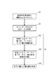
- Method for Manufacturing Printed Product 10 A method for manufacturing the printed product 10 will be described with reference to FIG.
- the reference target surface portion to be printed is imaged and scanned (step S1 in FIG. 6). Specifically, for example, a surface portion of an object to be reproduced is imaged with a CCD camera, a CMOS camera, or the like, and surface irregularities are measured using a laser displacement measuring device or the like. At this time, the imaged location is associated with the location where the unevenness is measured.
- Step S2 in FIG. 6 (2) Acquisition of Color Data and Convex Data As shown in FIG. 6, memory is obtained by calculating four colors of CMYK and the height of the convex portion (convex data) for each location from data obtained by imaging and scanning. (Step S2 in FIG. 6).
- the convex data is sequentially read from the memory, and clear ink is applied and dried to laminate the clear element layer. Go (step S31 in FIG. 6).
- the laminated clear layer 101 is composed of the four clear element layers 102 to 105. However, the number of laminated layers is changed according to the convex data.
- (3-2) Formation of Color Layer Color data is sequentially read from the memory, and the color layer 106 is formed so as to cover the upper surface and side surfaces of the stacked clear layer 101 (step S32 in FIG. 6).
- the color layer 106 is formed, for example, by applying UV (ultraviolet) curable ink containing pigments of each color using an ink jet apparatus and curing by applying UV irradiation.
- the light control layer 107 is formed so as to cover the color layer 106 and the exposed surface of the light diffusion plate 100 (step S33 in FIG. 6).
- the light control layer 107 is formed by, for example, applying a UV curable ink containing white particles made of a white pigment (for example, titanium oxide) using an inkjet apparatus and curing the ink by UV irradiation.
- a UV curable ink containing white particles made of a white pigment for example, titanium oxide
- step S3 in FIG. 6 printing (step S3 in FIG. 6) is completed, and the printed matter 10 is completed.
- FIG. 7 corresponds to FIG. 3A in the first embodiment, and the other configuration of the printed matter 30 can be the same as that in the first embodiment.
- a laminated clear layer 301 which is a laminated body of seven clear element layers 302 to 308, and a light control layer 309 are sequentially formed from the lower side in the Z-axis direction.
- the color layer 310 is laminated.
- the difference from the first embodiment is that the number of clear element layers 302 to 308 constituting the laminated clear layer 301 is 7, and the formation position of the light control layer 309 is below the color layer 310. In the point.
- each clear element layer 302 to 308 constituting the laminated clear layer 301 can be set to 0.010 mm to 0.030 mm, for example.
- the backlight 20 is also arranged on the back surface 30b side with respect to the printed matter 30 according to the present embodiment, and the light L 7 that is incident when the LED 21 is lit is transmitted through the printed matter 30. The light is emitted from the front surface 30a.
- the surface ratio of the clear element layer 308 serving as the base covers 2% to 50% (for example, 30%) in an area ratio in plan view. It is formed with.
- the light control layer 309 is formed in a halftone dot shape as in the first embodiment.
- the light control layer 309 is affected by the irregular reflection caused by the unevenness 302a. Can be suppressed. That is, when light traveling in an oblique direction with respect to the Z-axis direction due to irregular reflection directly enters the color layer 310, the wavelength of the emitted light changes due to the long optical path length.
- the light control layer 309 between the laminated clear layer 301 and the color layer 310, light traveling in an oblique direction can be changed in the optical path upward in the Z-axis direction. This is because the light incident on the light control layer 309 in an oblique direction has a high probability of being irradiated to the white particles contained therein.
- the printed material according to the present embodiment it is possible to suppress the influence of the irregular reflection on the laminated clear layer 301 when the light L 7 from the backlight is incident, and an image having a sense of depth such as a photograph can be obtained. This is suitable for increasing the number of clear element layers to be adopted.
- the number of clear element layers constituting the laminated clear layer 301 is seven, but may be eight or more (for example, ten). Thereby, the texture of the image can be enhanced.
- Embodiment 3 The configuration of the printed matter 40 according to Embodiment 3 will be described with reference to FIG. FIG. 8A also corresponds to FIG. 3A in the first embodiment, and the other configuration of the printed matter 40 can be the same as that in the first embodiment. .
- a laminated clear layer 301 that is a laminated body of seven clear element layers in order from the lower side in the Z-axis direction, a light control layer 309, a color layer 310, and a protective layer 411 are stacked.
- the difference from the second embodiment is that the upper surface of the color layer 310 is covered with a protective layer 411.
- the protective layer 411 is formed using, for example, a hard resin material.
- a hard resin material for example, polypropylene (PP), acrylic resin (PMMA), AS resin (SAN), ABS resin, polycarbonate (PC), etc. can be employed.
- the concentration of the light control layer 309 is also in the range of 2% to 50% (for example, 30%).
- the light control layer 309 is formed in a halftone dot shape as in the first embodiment.
- the color layer 310 is protected when the person touches the surface of the printed material, and the color layer 310 is adjusted by moisture or the like. It is possible to suppress deterioration of the optical layer 309 and the laminated clear layer 301. In particular, it is assumed that a person in contact with the printed material that has been subjected to ink embossing is touched, and even in this case, the color layer 310 can be reliably protected.
- a protective layer is disposed on the uppermost surface of the laminated structure to protect the light control layer or the laminated clear layer that is covered with the protective layer.
- the printed matter 45 according to this modification is configured with the laminated clear layer 301, the light control layer 309, and the color layer 310 laminated on the upper surface of the light diffusing plate 100 as described above.
- This is the same as the printed matter 40 according to the third aspect.
- the same is true in that the protective layer 51 is laminated on the color layer 310.
- the upper surface of the protective layer 451 is processed to have an unevenness (unevenness 451a), which results in a matte tone.
- unevenness 451a in the protective layer 451 is not necessarily provided on the entire surface of the protective layer 451, and considering the relationship with the image, the glossy protective layer 411 as shown in FIG. It is also possible to provide both a matte protective layer 451 as shown in FIG.
- the concentration of the light control layer 309 is also in the range of 2% to 50% (for example, 30%).
- the light control layer 309 is formed in a halftone dot shape as in the first embodiment.
- the color layer 310 can be protected, and the image quality of the image formed by the color layer 310 can be further enhanced by the matte protective layer 451. It becomes possible.
- Embodiment 4 The configuration of the printed matter 50 according to Embodiment 4 will be described with reference to FIG. 9 (a) to 9 (c), portions denoted by the same reference numerals as those described above are the same as those in the above configuration, and the description thereof is omitted. Further, the configuration of other portions not shown is the same as that of the first embodiment.
- the second dimming layer 512 is disposed between the upper surface of the light diffusing plate 100 and the laminated clear layer 101.
- the laminated form of the laminated clear layer 101, the color layer 106, and the light control layer 107 is the same as the printed matter 10 according to the first embodiment.
- the configuration of the second dimming layer 512 disposed between the light diffusing plate 100 and the laminated clear layer 101 is basically the same as that of the dimming layer 107 shown in FIG.
- the concentration of the second dimming layer 512 is in the range of 2% to 50%, and It is set higher than the light control layer 107.
- the concentration of the second dimming layer 512 is set higher than that of the dimming layer 107 located above is that the light incident from above is reflected as a function of the second dimming layer 512. It is because it is doing. However, if the concentration of the second dimming layer 512 is set higher than 50%, a large amount of light from the backlight 20 entering from the back surface of the light diffusing plate 100 is blocked. It is. Note that, in a partial region in plan view, when it is intended to completely block transmitted light, the density can be higher than 50% (for example, 100%). This can be considered in relation to the image.
- light L 8 is incident from the back surface 50 b of the printed matter 50 in a state where the LED 21 in the backlight 20 is turned on.
- the incident light passes through the second dimming layer 512, the laminated clear layer 101, the color layer 106, and the dimming layer 107, and is emitted from the front surface 50a (light L 9 ).
- the viewer perceives the image with the light L 9 .
- concentration of the second dimming layer 512 is too high, the attenuation of the transmitted light becomes too large, so it is necessary to keep it in the range of 2% to 50%.
- the concentration of the second light control layer 512 is particularly preferably 25% to 35% (for example, 30%) from the viewpoint of attenuation of transmitted light.
- the incident light L 10 is transmitted by the second dimming layer 512. Reflected upward in the Z-axis direction. The light reflected by the second dimming layer 512 passes through the laminated clear layer 101, the color layer 106, and the dimming layer 107 and is emitted from the front surface 50a (light L 11 ). The viewer can perceive the image also by the light L 11 .
- the viewer perceives the image by the transmitted light when the LED 21 in the backlight 20 is turned on and off, in other words, by the transmitted light.
- High image quality can be ensured both in the case and in the case where the viewer perceives the image by the reflected light.
- the arrangement position of the second light control layer 512 is not necessarily between the light diffusion plate 100 and the laminated clear layer 101, and is arranged between the clear element layers 102 to 105 in the laminated clear layer 101. And so on.
- the number of clear element layers constituting the laminated clear layer can be appropriately changed in consideration of the relationship with the image.
- Embodiment 5 The configuration of the printed material 60 according to Embodiment 5 will be described with reference to FIG. In FIG. 10, the parts denoted by the same reference numerals as in the fourth embodiment are the same as the structures of the respective parts in the fourth embodiment, and the description thereof is omitted. Further, the configuration of other portions not shown is the same as that of the first embodiment.
- the second dimming layer 512, the laminated clear layer 101, and the dimming layer 607 are sequentially laminated on the upper surface of the light diffusing plate 100.
- the light control layer 607 has the same configuration as that of the light control layer 107 in the first and fourth embodiments, and the second light control layer 512 is the same as in the fourth embodiment.
- a laminated color layer 606 is formed by laminating two color element layers 608 and 609 on the upper side in the Z-axis direction of the light control layer 607, and further four clear element layers 612 are formed thereon.
- a laminated clear layer 611 is formed by laminating .about.615.
- the laminated color layer 606 formed by laminating the two color element layers 608 and 609 is used for the color density of the portion to be expressed in dark color. This is to make it stand out.
- the reason why the laminated clear layer 611 is further formed on the laminated color layer 606 is to enhance the texture of the dark color portion in the image.
- the concentrations of the light control layer 607 and the second light control layer 607 are in the range of 2% to 50% in terms of the area ratio in plan view.
- the texture shown in FIG. 10 can be adopted to increase the texture of the dark color portion in the laminated color layer 606.
- a laminated clear layer 101 and a light control layer 107 are sequentially laminated on the upper surface of the light diffusion plate 100.
- the light control layer 107 has the same configuration as that of the first embodiment.
- the printed material 70 according to the present embodiment is different from the printed material 10 according to the first embodiment in that a color layer is not provided, and the light control layer 107 is directly laminated on the laminated clear layer 101. .
- concentration of the light control layer 107 according to the present embodiment is also in the range of 2% to 50% in the area ratio in plan view.
- the clear layer 812, the light control layer 807, the clear layer 813, the light control layer 808, the clear layer 814, the light control layer 809, and the clear layer 815 The light control layer 810 is sequentially laminated.
- the light control layers 807 to 810 are disposed between the layers of the laminated clear layer 811 composed of four layers.
- the concentrations of the light control layers 807 to 810 are 7% for the light control layers 807 to 809 and 10% for the light control layer 810, respectively.
- the layer thickness of each of the light control layers 807 to 810 is in the range of 0.010 mm to 0.030 mm, more preferably in the range of 0.010 mm to 0.020 mm (for example, 0. 0 mm) as in the first embodiment. 020 mm).
- the light control layer density a total of 31% (7% ⁇ 3 + 10%) of the respective densities of the light control layers 807 to 810 is referred to as “the light control layer density”.
- the clear layers 812 to 815 and the light control layers 807 to 810 are alternately laminated so that the viewer can feel a sense of depth. This is because each dot of the light control layers 807 to 810 is slightly shifted in the XY plane direction, and the light is refracted in an oblique direction due to the displacement of the dots, and a sense of depth can be felt. It is considered possible. It should be noted that the deviation of the dots in the light control layers 807 to 810 may be intentionally provided at the time of manufacture, or may be used for variation in accuracy of the ink jet apparatus.
- 12A is a cross-sectional image obtained by cutting the printed material 70 along the scanning direction of the ink-jet head at the time of ink application
- FIG. 12C is a cross-sectional image cut in a direction perpendicular to the scanning direction of the ink-jet head. It is.
- FIG. 13A shows an image of the printed material 70 taken from directly above the light emission side
- FIG. 13C shows an image taken from obliquely above.
- FIGS. 12B and 12D and FIGS. 13B and 13D The light transmission state of the printed matter 80 will be described with reference to FIGS. 12B and 12D and FIGS. 13B and 13D.
- 12B is a cross-sectional image obtained by cutting the printed matter 80 along the scanning direction of the ink jet head at the time of ink application
- FIG. 12D is a cross-sectional image cut in a direction orthogonal to the scanning direction of the ink jet head. It is.
- FIG. 13B is an image obtained by photographing the printed matter 80 from directly above the light emission side
- FIG. 13D is an image obtained by photographing from obliquely above.
- the laminated clear layers 101 and 301 that are the foundations of the light control layers 107, 309, and 607 are formed in a clear element layer 102 in a pyramid shape in cross section.
- the light control layers 107, 309, and 607 are formed so as to cover the upper surface and the side surfaces thereof.
- the clear layers 812 to 815 and the light control layers 807 to 810 are alternately laminated.
- the lamination of the clear element layer suppresses the coloring of the transmitted light, and the viewer perceives the transmitted light. This is because high image quality is realized in both cases where the viewer perceives the reflected light.
- the clear element layers 102 to 105, 302 to 308, and 812 to 815 constituting the laminated clear layers 101, 301, and 807 to 810 are viewed from the side surfaces. This corresponds to the transmission of light. That is, an image is formed over the entire range visible to the viewer, and the light control layers 107, 309, 607, and 807 to 810 are arranged, so that the viewer can perceive a high quality image.
- the laminated clear layers 101, 611, 811 are composed of four clear element layers 102-105, 612-615, 812-815, and the laminated clear layer 301 is seven layers.
- the clear element layers 302 to 308 are used.
- the number of laminated layers of the laminated clear layer is appropriately defined in relation to each part of the image to be expressed by the color layer. For example, what is necessary is just to change the number of laminated layers according to the surface states, such as cloth, wood, leather, and a metal surface.
- the density of the light control layer can be appropriately set in consideration of the number of clear layers to be formed, the color of the color layer, and the texture of the image to be expressed.
- the light control layer is formed by applying UV ink with an inkjet apparatus and drying it.
- concentration of the light control layer is formed through the process of ink application and drying, there is a correlation between the concentration of the light control layer and the layer thickness (minimum thickness).
- Table 1 shows the relationship between the concentration of the light control layer and the layer thickness.
- layer thickness refers to the maximum height of dots (see FIG. 4B) in the light control layer.
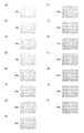
- Table 2 shows the relationship between color layer density and layer thickness when printed twice.
- the light diffusion plate 100 is also used as the substrate.
- the present invention is not limited to this.
- a substrate made of resin or glass may be employed. This increases the degree of freedom in selecting a material that can be employed as the substrate, and allows appropriate selection in relation to image quality.
- a flexible substrate such as a film can be used as the substrate, and a thin slice of Japanese paper or wood can be used as the substrate.
- the light control layers 107, 309, 607, 807 to 810, and the second light control layer 512 are printed in a dot pattern using an inkjet device.
- the present invention is not limited to this.
- the layer can be formed by bonding light-reflecting particles directly to the surface of the underlying layer using sputtering or CVD.
- the light-reflective particles contained in the light control layer particles made of a material other than titanium oxide, or a light-reflective coating on the surface of a transparent resin can be employed.
- the particle shape of the light reflective particles is not limited to a spherical shape. For example, a columnar or polyhedral shape can be employed.
- halftone dots when forming the light control layer on the surface of the underlying layer, it is not always necessary to use halftone dots.
- halftone can be used, and a form in which adjacent dots are connected can also be adopted.
- the constituent materials of the clear element layers 102 to 105, 302 to 308, 612 to 615, and 812 to 815 constituting the laminated clear layers 101, 301, 611, and 811 are as follows. Although not particularly mentioned, it is desirable to use a resin material from the viewpoint that it can be easily formed using an ink jet apparatus. However, an inorganic layer such as silicon oxide, silicon nitride, or silicon oxynitride can also be employed from the viewpoint of image quality.
- the color layers 106 and 310 and the laminated color layer 606 are configured by printing four color inks (C, M, Y, and K).
- C, M, Y, and K color inks
- the present invention is not limited to this.
- three or less of the above four colors can be used, or six colors including LC (light cyan) and KM (light magenta) in addition to the above four colors.
- ink for forming the color layer fluorescent ink or night-light ink can be used. Further, black light ink or the like can be used.
- the printed matter of the present invention includes monotone printing.
- the printed material 10, 30, 40, 45, 50, 60, 70, 80 as a part of the configuration of the illumination device 1 is adopted.
- the present invention is not limited to this, and the above effect can be obtained as a printed matter alone.
- the above-described effect can be achieved by mounting the printed matter on an existing lighting fixture or attaching the printed matter to a building window.
- a so-called edge light type device is used as the backlight 20, but the present invention is not limited to this.
- a direct type backlight can be adopted.
- the LED 21 is used as the light source.
- the present invention is not limited to this.
- a hot cathode lamp, a cold cathode lamp, an inorganic EL (electroluminescence) lamp, an organic EL lamp, or the like can be used.
- the emission color of the light source is not necessarily limited to white, and may emit light in various wavelength ranges.
- wavelength conversion member when a light source of a light emission color other than white is adopted, it is possible to arrange a wavelength conversion member in the optical path and convert it to white.
- a wavelength conversion member a wavelength conversion film including a phosphor layer or a semiconductor quantum dot may be employed.
- the present invention can be used in combination with a display panel in addition to a single lighting device.
- a flat display for example, a liquid crystal display panel, an organic EL panel, an inorganic EL panel, or the like
- a configuration without a light guide plate can be used. It can also be used to realize digital signage in combination with projectors.
- illumination in the present invention is used to include a display device and the like.
- the light control layer is arranged above the laminated clear layer and at least one of the layers of the plurality of laminated clear element layers, so that the image is perceived by the transmitted light.
- High image quality in both cases when the image is perceived by reflected light.
- the term “high image quality” here the difference in image quality perceived by the viewer between the case where the image is perceived by transmitted light and the case where the image is perceived by reflected light is suppressed. It is included to do.
- the present invention relates to a case where a viewer perceives an image with transmitted light and a case where a viewer perceives an image with reflected light, as part of interior decorations, advertising media, and construction materials (such as walls and ceilings). It is useful for realizing a printed matter that can obtain high image quality in both cases.
- Illumination device 10 30, 40, 45, 50, 60, 70, 80.
- Printed matter 20 Backlight 21.
- LED 22 Light guide plate 23.
- Reflector 80 Passage 100.
- Protective layer 512 Second light control layer 606.
Abstract
The printed matter according to the present invention is provided with a light-transmitting substrate, a layered clear layer, and a dimming layer. The layered clear layer is obtained by layering a plurality of light-transmitting clear element layers, and is arranged above the primary face of the substrate. The dimming layer has a function for adjusting the amount of transmitted light, and is arranged above the layered clear layer and/or between the plurality of layered clear layers. The dimming layer has a plurality of light-reflective particles, and is provided so as to cover a portion of the surface of the layer which is the base layer for the dimming layer. The plurality of light-reflective particles are each granular and the surfaces thereof have light-reflective properties. In plan view, the dimming layer covers 2% to 50% in terms of surface area ratio of the surface of the layer which is the base layer for the dimming layer.
Description
本発明は、印刷物に関し、特に立体印刷における画像品質の向上に係る技術に関する。
The present invention relates to a printed matter, and more particularly to a technique related to improvement of image quality in three-dimensional printing.
印刷された画像が立体的に知覚できるようにした印刷物が種々開発されている(特許文献1~5)。例えば、媒体上に印刷された画像の上にレンチキュラーレンズを形成したものや(特許文献1)、透明樹脂からなるクリア層により凹凸を形成し、その上または下に形成した画像を立体的に知覚できるようにしたもの(特許文献2,3)などがある。
Various printed materials have been developed so that printed images can be perceived in three dimensions (Patent Documents 1 to 5). For example, a lenticular lens is formed on an image printed on a medium (Patent Document 1), or an unevenness is formed by a clear layer made of a transparent resin, and an image formed on or below it is perceived three-dimensionally. There are those that can be made (Patent Documents 2 and 3).
また、媒体上に部分的に白色反射層を設け、その上に画像を印刷することで、白色反射層を設けた箇所と設けていない箇所との視覚効果の差異により立体的に知覚できるようにしたものなどもある(特許文献4,5)。
In addition, a white reflective layer is partially provided on the medium, and an image is printed on the medium so that a three-dimensional perception can be made due to the difference in visual effect between the portion where the white reflective layer is provided and the portion where the white reflective layer is not provided. (Patent Documents 4 and 5).
ところで、印刷物のオモテ面から光を照射し、その反射光により看者に画像を知覚させる形態に加え、媒体の裏面から光を入射させ、透過した光により看者に画像を知覚させるといった形態のものも開発されている。
By the way, in addition to the form in which light is irradiated from the front side of the printed material and the viewer perceives the image by the reflected light, the light is incident from the back side of the medium and the viewer perceives the image by the transmitted light. Things are also being developed.
しかしながら、立体的に知覚できるようにするためにクリア層を複数層形成した場合には、媒体の裏面から照射した光が色味を帯びてしまうという問題が生じる。例えば、白色で表現したい箇所にあっては、複数のクリア層が積層された箇所において黄色濁りを生じる。
However, when a plurality of clear layers are formed so that they can be perceived in three dimensions, there is a problem that light irradiated from the back surface of the medium is tinted. For example, in a portion that is desired to be expressed in white, yellow turbidity occurs in a portion where a plurality of clear layers are laminated.
このような透過光での色味を帯びるという問題は、透過光により画像を知覚する場合における画像品質を低下させる原因となる。
Such a problem of being tinted with transmitted light causes a reduction in image quality when an image is perceived by transmitted light.
本発明は、このような問題の解決を図ろうとなされたものであって、透過光により画像を知覚させる場合と、反射光で画像を知覚させる場合と、の両場合で高い画像品質を得ることができる印刷物を提供することを目的とする。
The present invention has been made to solve such problems, and obtains high image quality in both cases where an image is perceived by transmitted light and an image is perceived by reflected light. The purpose is to provide a printed material that can be printed.
本発明の一態様に係る印刷物は、基板と、積層クリア層と、調光層と、を備える。
The printed matter according to one embodiment of the present invention includes a substrate, a laminated clear layer, and a light control layer.
基板は、光透過性を有する。
The substrate has optical transparency.
積層クリア層は、光透過性のクリア要素層が複数積層されてなり、基板の一方の主面(一主面)の上方に配置されている。
The laminated clear layer is formed by laminating a plurality of light-transmitting clear element layers, and is disposed above one main surface (one main surface) of the substrate.
調光層は、透過する光の光量を調整する機能を有し、積層クリア層の上方および複数積層されてなるクリア層の層間の少なくとも一方に配置されている。
The light control layer has a function of adjusting the amount of transmitted light, and is disposed above the laminated clear layer and at least one of the layers of a plurality of laminated clear layers.
本態様における調光層は、複数の光反射性粒子を有し、その下地となる層の表面の一部を覆って設けられている。複数の光反射性粒子は、それぞれが粒状をしており、表面が光反射性を有する。そして、調光層は、平面視において、下地となる層の表面に対し、面積比で2%~50%を覆っている。
The light control layer in this embodiment has a plurality of light reflective particles and is provided so as to cover a part of the surface of the layer serving as the base. Each of the plurality of light reflective particles is granular, and the surface has light reflectivity. The light control layer covers an area ratio of 2% to 50% with respect to the surface of the underlying layer in plan view.
上記態様に係る印刷物では、透過光により画像を知覚させる場合と、反射光で画像を知覚させる場合と、の両場合で高い画像品質を実現することができる。
In the printed matter according to the above aspect, high image quality can be realized both in the case where an image is perceived by transmitted light and the case where an image is perceived by reflected light.
[本発明の各態様]
本発明に一態様に係る印刷物は、基板と、積層クリア層と、調光層と、を備える。 [Embodiments of the present invention]
The printed matter according to one aspect of the present invention includes a substrate, a laminated clear layer, and a light control layer.
本発明に一態様に係る印刷物は、基板と、積層クリア層と、調光層と、を備える。 [Embodiments of the present invention]
The printed matter according to one aspect of the present invention includes a substrate, a laminated clear layer, and a light control layer.
基板は、光透過性を有する。
The substrate has optical transparency.
積層クリア層は、光透過性のクリア要素層が複数積層されてなり、基板の一方の主面(一主面)の上方に配置されている。なお、本明細書において、「上方に配置」とは、下地となる層の上に直に配置する場合と、下地となる層の上に他の層を介して配置する場合と、の両場合を含む。
The laminated clear layer is formed by laminating a plurality of light-transmitting clear element layers, and is disposed above one main surface (one main surface) of the substrate. In this specification, “arranged upward” means both the case where it is disposed directly on the underlying layer and the case where it is disposed on the underlying layer via another layer. including.
調光層は、透過する光の光量を調整する機能を有し、積層クリア層の上方および複数積層されてなるクリア層の層間の少なくとも一方に配置されている。
The light control layer has a function of adjusting the amount of transmitted light, and is disposed above the laminated clear layer and at least one of the layers of a plurality of laminated clear layers.
本態様における調光層は、複数の光反射性粒子を有し、その下地となる層の表面の一部を覆って設けられている。複数の光反射性粒子は、それぞれが粒状をしており、表面が光反射性を有する。そして、調光層は、平面視において、下地となる層の表面に対し、面積比で2%~50%を覆っている。
The light control layer in this embodiment has a plurality of light reflective particles and is provided so as to cover a part of the surface of the layer serving as the base. Each of the plurality of light reflective particles is granular, and the surface has light reflectivity. The light control layer covers an area ratio of 2% to 50% with respect to the surface of the underlying layer in plan view.
上記態様に係る印刷物では、調光層が下地となる層の表面に対し、面積比で2%~50%の範囲(「2%~50%の濃度」と記載する場合がある。)で覆うよう設けられているので、透過光により画像を知覚させる場合と、反射光で画像を知覚させる場合と、の両場合で高い画像品質を実現することができる。
In the printed matter according to the above aspect, the light control layer covers the surface of the underlying layer with an area ratio of 2% to 50% (may be described as “2% to 50% density”). Therefore, high image quality can be realized both in the case where the image is perceived by the transmitted light and the case where the image is perceived by the reflected light.
なお、上記態様に係る印刷物では、調光層を積層クリア層の上方に配置する態様を採用する場合には、例えば、黒色(暗さ)や奥行き感を強調するなどの画像の高い品質を得る上でも効果を奏する。
In addition, in the printed matter according to the above aspect, when adopting an aspect in which the light control layer is disposed above the laminated clear layer, for example, high image quality such as emphasizing black (darkness) or a sense of depth is obtained. It also has an effect on the top.
本発明の一態様に係る印刷物では、上記構成において、調光層が網点状に設けられている。このような構成を採用する場合にも、透過光により画像を知覚させる場合と、反射光で画像を知覚させる場合と、の両場合で高い画像品質を実現することができる。
In the printed matter according to one aspect of the present invention, the light control layer is provided in a dot pattern in the above configuration. Even when such a configuration is adopted, high image quality can be realized both in the case where an image is perceived by transmitted light and the case where an image is perceived by reflected light.
なお、「網点」とは、印刷において、下地の表面上に対し、小さな点のパターン(ドットパターン)で層を形成することをいい、隣り合うドット同士が繋がった場合も含む。
The “halftone dot” means that a layer is formed with a small dot pattern (dot pattern) on the surface of the base in printing, and includes a case where adjacent dots are connected.
本発明の一態様に係る印刷物では、上記構成において、さらにカラー層を備える構成とすることができる。カラー層は、1色または複数色を以って基板の一主面に沿った方向に形成され、基板の一主面の上方に配置されている。
The printed matter according to one embodiment of the present invention may be configured to further include a color layer in the above configuration. The color layer is formed in a direction along one principal surface of the substrate with one color or a plurality of colors, and is disposed above the one principal surface of the substrate.
このように、カラー層を備える構成を採用する態様では、表現力豊かな画像を看者に知覚させることができる。また、調光層を備えることにより、特に透過光により知覚させる場合に、優れた色再現性を実現することができる。
As described above, in the aspect of adopting the configuration including the color layer, it is possible to make the viewer perceive an image rich in expressive power. In addition, by providing the light control layer, it is possible to realize excellent color reproducibility, particularly when perceived by transmitted light.
本発明の一態様(仮に、「第1の態様」とする。)に係る印刷物では、上記構成において、カラー層が積層クリア層の上面を被覆するように配置されており、調光層が、カラー層の上面の一部と、積層クリア層およびカラー層の側面の一部を被覆するように配置されている。このように、調光層を積層クリア層およびカラー層の上の一部を被覆するように配置することで、基板の裏面(他方の主面)に光を入射させ、積層クリア層を透過させた場合においても、光が色味を帯びる(例えば、黄色濁り)ことを抑制することができる。
In the printed matter according to one aspect of the present invention (assuming to be “first aspect”), in the above configuration, the color layer is disposed so as to cover the top surface of the laminated clear layer, and the light control layer is It arrange | positions so that a part of upper surface of a color layer and a part of side surface of a lamination | stacking clear layer and a color layer may be coat | covered. In this way, by arranging the light control layer so as to cover a part of the laminated clear layer and the color layer, light is incident on the back surface (the other main surface) of the substrate and the laminated clear layer is transmitted. Even in this case, it is possible to prevent the light from being colored (for example, yellow turbidity).
従って、カラー層で構成された画像を看者が知覚するに際して、反射光による場合と透過光による場合との両場合で高い画像品質を確保することができる。特に、画像において、白色や淡色での表現をしようとする場合になどには、画像品質の向上を図るという観点から効果的である。
Therefore, when an observer perceives an image composed of a color layer, high image quality can be ensured in both cases of reflected light and transmitted light. In particular, it is effective from the viewpoint of improving image quality when an image is to be expressed in white or light color.
なお、第1の態様においては、調光層の上に更に薄い層厚のクリア層を加えることによって、透明感のある画像を再現することも可能となる。
In the first aspect, it is possible to reproduce a transparent image by adding a clear layer having a thinner thickness on the light control layer.
本発明の一態様(仮に、「第2の態様」とする。)に係る印刷物では、上記構成において、第2調光層を備える。第2調光層は、上記一主面と積層クリア層との間に配置され、透過する光の光量を調整する機能を有する。そして、第2調光層も、それぞれの表面が光反射特性を有し、それぞれ粒状をした複数の光反射性粒子を有してなる。第2調光層は、平面視において、その下地となる層の表面に対し、面積比で2%~50%の範囲で覆うよう設けられている。
The printed matter according to one aspect of the present invention (assuming “second aspect”) includes the second light control layer in the above configuration. A 2nd light control layer is arrange | positioned between the said one main surface and a lamination | stacking clear layer, and has the function to adjust the light quantity of the light to permeate | transmit. The second light control layer also has a plurality of light-reflective particles each having a light-reflective property on each surface and each having a granular shape. The second light control layer is provided so as to cover an area ratio of 2% to 50% with respect to the surface of the underlying layer in plan view.
なお、透過光を完全に遮光しようとする領域に関しては、例えば、100%の濃度で反射層(白色層)を形成することで対応できる。
It should be noted that the region in which the transmitted light is to be completely blocked can be dealt with by forming a reflective layer (white layer) with a concentration of 100%, for example.
このように、基板の一主面と積層クリア層との間に、第2調光層を配置する場合には、反射光により看者が画像を知覚する場合に、上方から入射した光の一部が第2調光層で反射される。このため、上方から入射した光に対する反射光の光量割合を増加させることができる。
As described above, when the second light control layer is disposed between one main surface of the substrate and the laminated clear layer, when the viewer perceives an image by reflected light, The portion is reflected by the second light control layer. For this reason, the light quantity ratio of the reflected light with respect to the light incident from above can be increased.
従って、第2の態様に係る印刷物では、透過光により画像を知覚させる場合と、反射光で画像を知覚させる場合と、の両場合で更に画像品質の向上を図ることができる。
Therefore, in the printed matter according to the second aspect, it is possible to further improve the image quality in both the case where the image is perceived by the transmitted light and the case where the image is perceived by the reflected light.
本発明の一態様に係る印刷物では、上記構成において、下地となる層の表面を第2調光層が被覆する比率(濃度)は、下地となる層の表面を調光層が被覆する比率(濃度)よりも高い。これにより、第2調光層における光反射機能を確実に得ることができる。
In the printed matter according to one embodiment of the present invention, in the above configuration, the ratio (density) at which the surface of the base layer is covered with the second light control layer is the ratio at which the light control layer covers the surface of the base layer ( Higher than (concentration). Thereby, the light reflection function in a 2nd light control layer can be acquired reliably.
本発明の一態様(仮に、「第3の態様」とする。)に係る印刷物では、上記構成において、調光層が積層クリア層の上面および側面の各一部を被覆するように配置されており、カラー層が調光層の上面を被覆するように配置されている。このように、調光層を、積層クリア層の上の一部を被覆し、且つ、カラー層の下に配置する態様では、基板の裏面(他方の主面)から光を照射して透過光により看者に画像を知覚させる場合に、積層クリア層での光の乱反射による色調への影響を抑制することができる。なお、積層クリア層での透過光の乱反射は、例えば、各クリア要素層の上側あるいは下側の表面の凹凸などにより生じるものと考えられる。
In the printed matter according to one aspect of the present invention (tentatively referred to as “third aspect”), in the above configuration, the light control layer is disposed so as to cover each part of the upper surface and the side surface of the laminated clear layer. The color layer is arranged so as to cover the upper surface of the light control layer. In this manner, in the aspect in which the light control layer covers a part of the laminated clear layer and is disposed under the color layer, light is irradiated from the back surface (the other main surface) of the substrate to transmit light. Thus, when making the viewer perceive an image, it is possible to suppress the influence on the color tone due to the irregular reflection of light in the laminated clear layer. In addition, it is thought that the irregular reflection of the transmitted light in the laminated clear layer is caused by, for example, irregularities on the upper or lower surface of each clear element layer.
従って、第3の態様に係る印刷物においても、カラー層で構成された画像を看者が知覚する場合と、反射光による場合と透過光による場合と、の両場合で高い画像品質を確保することができる。
Therefore, even in the printed matter according to the third aspect, it is possible to ensure high image quality both in the case where the viewer perceives the image composed of the color layer and in the case where the reflected light and the transmitted light are used. Can do.
本発明の一態様に係る印刷物では、上記構成において、カラー層が複数のカラー要素層が積層されてなる積層体である。このようにカラー層を多層構造とすることにより、画像の質感を高めることができる。
In the printed material according to one embodiment of the present invention, in the above structure, the color layer is a stacked body in which a plurality of color element layers are stacked. Thus, the texture of the image can be enhanced by providing the color layer with a multilayer structure.
本発明の一態様に係る印刷物では、上記構成において、さらに保護層を備える。保護層は、光透過性を有し、積層構造上面を被覆するように配置されている(印刷物の最上面に保護層が配置されている)。このように、積層構造の再上面に保護層を配置する態様では、積層クリア層の配置によって疑似的なエンボス加工を施すことで、画像を知覚した看者が印刷物の表面に手を触れた場合にあっても、調光層やクリア要素層などの保護層の下に配置される層を保護することができる。また、カラー層を備える態様にあっては、保護層の種類を選ぶことによって、カラー層などの色褪せを防ぐことなども可能となる。
The printed matter according to one embodiment of the present invention further includes a protective layer in the above configuration. The protective layer has light transmittance and is disposed so as to cover the upper surface of the laminated structure (the protective layer is disposed on the uppermost surface of the printed material). As described above, in the aspect in which the protective layer is arranged on the upper surface of the laminated structure, when a viewer who perceives the image touches the surface of the printed matter by performing pseudo embossing by arranging the laminated clear layer Even in this case, the layer disposed under the protective layer such as the light control layer or the clear element layer can be protected. Moreover, in the aspect provided with a color layer, it becomes possible to prevent fading of a color layer etc. by selecting the kind of protective layer.
本発明の一態様に係る印刷物では、上記構成において、保護層がマット処理を施されている。例えば、表面に凹凸を形成することで実現することができる。このように、保護層の表面にマット処理(艶消し処理)を施す態様では、当該マット処理を施した領域と施していない領域とで、画像の質感を変えることができる。例えば、光沢のある金属表面などを画像で表現しようとする領域についてはマット処理を施さず、グロス調としておき、表面がザラザラとした物を画像で表現しようとする領域についてはマット処理を施すなどが可能である。
In the printed matter according to one embodiment of the present invention, the protective layer is matted in the above configuration. For example, it can be realized by forming irregularities on the surface. Thus, in the aspect which performs the mat process (matte process) on the surface of a protective layer, the texture of an image can be changed with the area | region which did not perform the said mat process. For example, areas that are intended to represent glossy metal surfaces, etc., are not subjected to mat processing, but are made glossy, and areas that are intended to be rendered with a rough surface are subjected to mat processing. Is possible.
本発明の一態様に係る印刷物では、上記構成において、積層クリア層および調光層よりも上方には、光透過性のクリア要素層が複数積層されてなる第2積層クリア層が配置されている。このように第2積層クリア層を配置することにより、画像における色調をより強調することができる。特に、カラー層を備える態様では、カラー層における濃色部分の色をより強調することができ、さらに高い質感を実現することができる。
In the printed material according to one aspect of the present invention, in the above configuration, the second laminated clear layer in which a plurality of light-transmitting clear element layers are laminated is disposed above the laminated clear layer and the light control layer. . By arranging the second laminated clear layer in this way, the color tone in the image can be further emphasized. In particular, in the aspect provided with the color layer, the color of the dark color portion in the color layer can be further emphasized, and a higher texture can be realized.
本発明の一態様に係る印刷物では、上記構成において、下地となる層の表面を調光層が被覆する比率(濃度)が面積比で25%~35%の範囲で調整されている。この濃度範囲とすることにより、透過光により画像を看者が視認する場合と、反射光により画像を看者が視認する場合と、の両場合でのより高い印刷品質を確保することができる。
In the printed matter according to one aspect of the present invention, in the above configuration, the ratio (density) of the light control layer covering the surface of the layer serving as the base is adjusted in the range of 25% to 35% in terms of area ratio. By setting this density range, it is possible to ensure higher print quality in both cases where the viewer visually recognizes the image with transmitted light and when the viewer visually recognizes the image with reflected light.
本発明の一態様に係る印刷物では、上記構成において、調光層において、調光層に含まれる光反射性粒子が白色顔料からなる。このような構成とすることにより、例えば、インクジェット装置を用いUV(紫外線)硬化インクを滴下して調光層を形成することができ、容易に形成することができる。なお、下地となる層に対するインクの親液性を考慮して、下地となる層の表面に予めプライマーを塗布しておくこともできる。
In the printed matter according to one aspect of the present invention, in the above-described configuration, in the light control layer, the light reflective particles contained in the light control layer are made of a white pigment. By adopting such a configuration, for example, a light control layer can be formed by dropping UV (ultraviolet) curable ink using an ink jet device, and can be easily formed. In consideration of the lyophilicity of the ink with respect to the underlying layer, a primer can be applied in advance to the surface of the underlying layer.
本発明の一態様に係る印刷物では、上記構成において、調光層の層厚が0.010mm~0.030mmの範囲である。調光層の層厚を上記範囲に規定することにより、透過光により画像を知覚させる場合と、反射光により画像を知覚させる場合と、の両場合で高い画像品質を確保することができる。
In the printed material according to one aspect of the present invention, in the above configuration, the layer thickness of the light control layer is in the range of 0.010 mm to 0.030 mm. By defining the layer thickness of the light control layer within the above range, high image quality can be ensured in both cases where an image is perceived by transmitted light and when an image is perceived by reflected light.
なお、本発明の一態様に係る印刷物では、上記構成において、基板として、樹脂またはガラスからなる基板を採用することができる。
Note that in the printed material according to one embodiment of the present invention, in the above structure, a substrate made of resin or glass can be employed as the substrate.
以下では、実施の形態について、図面を参酌しながら説明する。
Hereinafter, embodiments will be described with reference to the drawings.
なお、以下の説明に係る実施の形態は、本発明の構成上の特徴および当該構成上の特徴から奏される作用効果を分かりやすく説明するための例として用いるものであって、本発明は、その本質的な特徴部分を除き、以下の形態に何ら限定を受けるものではない。
In addition, the embodiment according to the following description is used as an example for easily explaining the structural features of the present invention and the effects obtained from the structural features. Except for the essential features, the present invention is not limited to the following forms.
[実施の形態1]
1.照明装置1の概略構成
本実施の形態に係る照明装置1の概略構成を、図1を用い説明する。 [Embodiment 1]
1. Schematic Configuration of Lighting Device 1 A schematic configuration of thelighting device 1 according to the present embodiment will be described with reference to FIG.
1.照明装置1の概略構成
本実施の形態に係る照明装置1の概略構成を、図1を用い説明する。 [Embodiment 1]
1. Schematic Configuration of Lighting Device 1 A schematic configuration of the
図1に示すように、バックライト20と印刷物10とを有し構成されている。照明装置1には、この他にドライバー回路なども備えるが、図示を省略している。
As shown in FIG. 1, it has a backlight 20 and a printed product 10. In addition to this, the illuminating device 1 is also provided with a driver circuit or the like, which is not shown.
印刷物10は、その一方の主面(オモテ面)10aに疑似的なエンボス処理(インクエンボス処理)が施されている。
The printed material 10 is subjected to pseudo embossing (ink embossing) on one main surface (front surface) 10a thereof.
バックライト20は、光源としてのLED21を備えるものであって、導光板22の端面に対向配置されている(エッジライト方式)。導光板22のZ軸方向上面には、印刷物10が密着する状態で載置されている。導光板23のZ軸方向下面およびLED21が対向しない端面は、反射板23で覆われている。
The backlight 20 includes an LED 21 as a light source, and is disposed to face the end surface of the light guide plate 22 (edge light method). On the upper surface in the Z-axis direction of the light guide plate 22, the printed material 10 is placed in close contact. The lower surface of the light guide plate 23 in the Z-axis direction and the end surface that the LED 21 does not face are covered with the reflection plate 23.
2.印刷物10の概略構成
印刷物10の概略構成について、図2を用い説明する。図2は、図1のA部を拡大した模式断面図である。 2. Schematic Configuration of Printed Product 10 A schematic configuration of the printedproduct 10 will be described with reference to FIG. FIG. 2 is an enlarged schematic cross-sectional view of a portion A in FIG.
印刷物10の概略構成について、図2を用い説明する。図2は、図1のA部を拡大した模式断面図である。 2. Schematic Configuration of Printed Product 10 A schematic configuration of the printed
図2に示すように、基板としての光拡散板100をベースに形成されており、一方の主面(オモテ面)10aにインクエンボス処理が施されている。一方、裏面10bは、導光板22に対して密着する状態で配置される(図1を参照)。ここで、光拡散板100は、アクリル樹脂から構成されており、表面をマット調とすることで光拡散性能が付与されている。
As shown in FIG. 2, it is formed based on a light diffusing plate 100 as a substrate, and one main surface (front surface) 10a is subjected to an ink embossing process. On the other hand, the back surface 10b is disposed in close contact with the light guide plate 22 (see FIG. 1). Here, the light diffusing plate 100 is made of an acrylic resin, and light diffusing performance is imparted by making the surface matte.
光拡散板100のZ軸方向上面には、複数の凸部10d1,10d2,・・が形成され、隣り合う凸部10d1,10d2,・・間が凹部10c,・・となっている。凸部10d1,10d2,・・の領域では、光拡散板100の上面にクリア要素層102~105が積層されている。複数のクリア要素層102~105の積層体を積層クリア層101と呼ぶことにする。
A plurality of convex portions 10d 1 , 10d 2 ,... Are formed on the upper surface in the Z-axis direction of the light diffusing plate 100, and the adjacent convex portions 10d 1 , 10d 2 ,. Yes. In the regions of the convex portions 10d 1 , 10d 2 ,..., Clear element layers 102 to 105 are laminated on the upper surface of the light diffusing plate 100. A laminated body of a plurality of clear element layers 102 to 105 will be referred to as a laminated clear layer 101.
積層クリア層101の上面および側面を被覆するように、カラー層106が積層されている。図では、カラー層106を模式的に図示しているが、詳細には、C(青;シアン)、M(赤;マゼンダ)、Y(黄;イエロー)、K(黒;キープレート)の4色のインクをフルカラー印刷して形成されている。なお、インクは、UV硬化型のものが用いられ、インクジェット装置を用い塗布されている。
The color layer 106 is laminated so as to cover the upper surface and side surfaces of the laminated clear layer 101. In the figure, the color layer 106 is schematically illustrated. However, in detail, C (blue; cyan), M (red; magenta), Y (yellow; yellow), K (black; key plate) 4 It is formed by full color printing of colored ink. The ink is UV curable and is applied using an ink jet apparatus.
カラー層106の上面を被覆するように、調光層107が形成されている。調光層107は、凹部10cにおける光拡散板100の表面も被覆するように形成されている。調光層107については、UV硬化型のインクを用い網点で形成されており、インクの塗布には、インクジェット装置が用いられている。なお、調光層107の形成に際しては、下地となる層に対するインクの親液性を考慮して、予め下地となる層の表面にプライマーを塗布しておくこともできる。
A light control layer 107 is formed so as to cover the upper surface of the color layer 106. The light control layer 107 is formed so as to also cover the surface of the light diffusion plate 100 in the recess 10c. The light control layer 107 is formed of halftone dots using UV curable ink, and an ink jet apparatus is used for ink application. In forming the light control layer 107, in consideration of the lyophilicity of the ink with respect to the underlying layer, a primer can be applied to the surface of the underlying layer in advance.
印刷物10においては、LED21の点灯時には裏面10bからオモテ面10aに向けて光L1が透過し、LED21の消灯時にはオモテ面10aから入射した光L2が反射することで、看者の側へと出射される。
In the printed matter 10, the light L 1 is transmitted from the back surface 10 b toward the front surface 10 a when the LED 21 is turned on, and the light L 2 incident from the front surface 10 a is reflected when the LED 21 is turned off, so that the light L 1 is reflected. Emitted.
なお、図2に示すように、本実施の形態では、クリア要素層102~105が、ともに台形状の断面形状をしており、Z軸方向下側から順にピラミッド状に積層されている。
As shown in FIG. 2, in the present embodiment, the clear element layers 102 to 105 each have a trapezoidal cross-sectional shape and are stacked in a pyramid shape in order from the lower side in the Z-axis direction.
しかし、各層の断面形状については、これに限定されるものではなく、一部の層が上下の層と同じ断面サイズを有していてもよいし、全ての層が同じ断面サイズを有する形態とすることもできる。
However, the cross-sectional shape of each layer is not limited to this, and some layers may have the same cross-sectional size as the upper and lower layers, or all layers have the same cross-sectional size. You can also
ただし、図2に示すようにピラミッド状に積層することによって、カラー層106を積層クリア層101の側面にも形成することができ、看者が視認し得る全領域に万遍なく画像を形成することができる。
However, as shown in FIG. 2, by laminating in a pyramid shape, the color layer 106 can also be formed on the side surface of the laminated clear layer 101, and an image is uniformly formed in the entire region that can be visually recognized by the viewer. be able to.
また、各層の上角部分に丸みをもたせることにより、看者が視認する画像の品質を向上させることができる。
Also, by rounding the upper corners of each layer, it is possible to improve the quality of images viewed by the viewer.
3.印刷物10に入射した光の進行と、調光層107が果たす役割
印刷物10に入射した光の進行と、調光層107が果たす役割について、図3を用い説明する。図3は、(a)が本実施の形態の場合、(b)、(c)が比較例の場合を示す。 3. The progress of the light incident on the printedmatter 10 and the role played by the light control layer 107 The progress of the light incident on the printed matter 10 and the role played by the light control layer 107 will be described with reference to FIG. FIG. 3 shows a case where (a) is the present embodiment, and (b) and (c) are comparative examples.
印刷物10に入射した光の進行と、調光層107が果たす役割について、図3を用い説明する。図3は、(a)が本実施の形態の場合、(b)、(c)が比較例の場合を示す。 3. The progress of the light incident on the printed
図3(a)に示すように、印刷物10に対しては、LED21の点灯時においては裏面10bより入射した光L1が、カラー層106および調光層107を透過して出射する(出射光L3)。一方、LED21の消灯時においては、オモテ面10aより入射した光L2が、カラー層106よりもZ軸方向下方の界面などで反射し、反射光がカラー層106および調光層107を透過して出射する(出射光L3)。
As shown in FIG. 3A, for the printed matter 10, when the LED 21 is lit, the light L 1 incident from the back surface 10b is transmitted through the color layer 106 and the light control layer 107 and emitted (emitted light). L 3). On the other hand, when the LED 21 is turned off, the light L 2 incident from the front surface 10 a is reflected at the interface below the color layer 106 in the Z-axis direction, and the reflected light passes through the color layer 106 and the light control layer 107. Are emitted (emitted light L 3 ).
ここで、調光層107は、層を透過する光の一部を遮光する機能を有する。そして、一部の光については、そのまま透過させる。本実施の形態に係る調光層107は、網点状に形成されており、光の透過光量と反射光量とのバランスをとる働きをする。具体的な構成については、後述する。
Here, the light control layer 107 has a function of blocking a part of light transmitted through the layer. And some light is permeate | transmitted as it is. The light control layer 107 according to the present embodiment is formed in a halftone dot shape, and functions to balance the transmitted light amount and the reflected light amount. A specific configuration will be described later.
また、印刷物10では、凸部10d1,10d2を形成するために、積層クリア層101を形成しているが、特に透過光においては、黄色濁りを生じた光が出射しやすい傾向にある。
In the printed matter 10, the laminated clear layer 101 is formed in order to form the convex portions 10 d 1 and 10 d 2 , but in particular, transmitted light tends to emit light with yellow turbidity.
しかしながら、本実施の形態に係る印刷物10では、カラー層106の上に調光層107を形成しているので、積層クリア層101に起因する黄色濁りを抑制することができ、透過光により画像を知覚させる場合にも、カラー層106を透過して出射される光L3での色再現性に優れる。特に、カラー層106が淡色を中心とするものである場合には、その色再現性という観点から優れる。
However, in the printed matter 10 according to the present embodiment, since the light control layer 107 is formed on the color layer 106, yellow turbidity due to the laminated clear layer 101 can be suppressed, and an image is transmitted by transmitted light. Even in the case of perception, the color reproducibility with the light L 3 that is transmitted through the color layer 106 and emitted is excellent. In particular, when the color layer 106 is centered on light colors, it is excellent from the viewpoint of color reproducibility.
図3(b)に示すように、基板900の上に、積層クリア層901、カラー層906が順に積層され、カラー層906のZ軸方向上側に調光層を備えない構成の印刷物90を想定する。印刷物90に対し、その裏面90bから光L1を入射させ、印刷物90を透過して光L4が出射する場合において、積層クリア層901の透過に起因して、黄色濁りを生じることになる。なお、図示を省略しているが、反射光により画像を認識する場合にも黄色濁りを生じるものと考えられるが、透過光による場合に比べて、その度合いは軽い。この原因については詳しくは解明されていないが、発明者は、反射光の場合には積層クリア層の上部での反射が存在し、その場合には光が通過するクリア要素層間の界面が少ないのに対し、透過光については、積層クリア層における全てのクリア要素層間の界面を通過することによる光の屈折などにより一部の波長域の吸収が大きいことに起因するものであると考察した。
As shown in FIG. 3B, a printed material 90 is assumed in which a laminated clear layer 901 and a color layer 906 are sequentially laminated on a substrate 900, and a light control layer is not provided on the upper side of the color layer 906 in the Z-axis direction. To do. When light L 1 is incident on the printed material 90 from the back surface 90 b and transmitted through the printed material 90 and emitted light L 4 , yellow turbidity is generated due to the transmission of the laminated clear layer 901. Although illustration is omitted, it is considered that yellow turbidity is also generated when an image is recognized by reflected light, but the degree is lighter than that by transmitted light. Although the cause of this is not clarified in detail, in the case of reflected light, the inventor has reflection on the upper part of the laminated clear layer, in which case there are few interfaces between the clear element layers through which light passes. On the other hand, the transmitted light was considered to be due to the fact that absorption in a part of the wavelength range is large due to refraction of light caused by passing through the interfaces between all the clear element layers in the laminated clear layer.
よって、図3(b)に示す比較例1の場合、透過光と反射光とで患者が知覚する画像の色合いが違ったものとなる。即ち、特に透過光により看者に画像を知覚させる場合の画像品質の低下を招いてしまうことが考えられる。
Therefore, in the case of Comparative Example 1 shown in FIG. 3B, the color of the image perceived by the patient differs between the transmitted light and the reflected light. That is, it is conceivable that the quality of the image is deteriorated particularly when the viewer perceives the image with transmitted light.
さらに、図3(c)に示すように、紙などの媒体を基板910として用い、その上に、白色反射層917、積層クリア層911、カラー層916を順に形成してなる印刷物91を想定する。このような構成の印刷物91に対してZ軸方向上方より入射した光L5は、白色反射層917で光量の大部分が反射され、カラー層916を透過してオモテ面91aより出射される(光L6)。この比較例2の形態では、透過光による画像の知覚は意図していないために、白色反射層917の機能として上方より入射した光L5をできるだけ反射させることにある。このため、比較例2の印刷物91に対して裏面より光を照射しても、殆ど透過せず、透過光による画像を看者は知覚できない。即ち、光反射を目的として設けられた白色反射層917は、Z軸方向上方よりの光だけでなく、Z軸方向下方よりの光についても同様に反射することとなる。
Furthermore, as shown in FIG. 3C, a printed material 91 is assumed in which a medium such as paper is used as the substrate 910, and a white reflective layer 917, a laminated clear layer 911, and a color layer 916 are sequentially formed thereon. . Light L 5 incident on the printed matter 91 having such a configuration from above in the Z-axis direction is mostly reflected by the white reflective layer 917, passes through the color layer 916, and is emitted from the front surface 91 a ( light L 6). In the form of this comparative example 2, since the perception of the image by the transmitted light is not intended, the function of the white reflective layer 917 is to reflect the light L 5 incident from above as much as possible. For this reason, even if the printed matter 91 of Comparative Example 2 is irradiated with light from the back surface, it hardly transmits, and the viewer cannot perceive an image of the transmitted light. That is, the white reflection layer 917 provided for the purpose of light reflection reflects not only light from the upper side in the Z-axis direction but also light from the lower side in the Z-axis direction.
4.各層の厚みと調光層107の構成
(各層の厚み)
図4(a)を用い、本実施の形態で一例として採用した各層の層厚について説明する。 4). The thickness of each layer and the configuration of the light control layer 107 (thickness of each layer)
The layer thickness of each layer employed as an example in the present embodiment will be described with reference to FIG.
(各層の厚み)
図4(a)を用い、本実施の形態で一例として採用した各層の層厚について説明する。 4). The thickness of each layer and the configuration of the light control layer 107 (thickness of each layer)
The layer thickness of each layer employed as an example in the present embodiment will be described with reference to FIG.
図4(a)に示すように、本実施の形態に係る印刷物10においては、積層クリア層101の総厚tCAが0.08mm程度である。そして、積層クリア層101を構成するクリア要素層102~105の各層厚tC1が0.02mm程度である。なお、本実施の形態では、4層のクリア要素層102~105の積層体として積層クリア層101を構成しているが、表現しようとする画像に応じて積層層数を変化させることもできる。また、各クリア要素層の層厚については、互いに同一である必要は必ずしもなく、異なっていてもよい。
As shown in FIG. 4A, in the printed matter 10 according to the present embodiment, the total thickness t CA of the laminated clear layer 101 is about 0.08 mm. Each layer thickness t C1 of the clear element layers 102 to 105 constituting the laminated clear layer 101 is about 0.02 mm. In the present embodiment, the laminated clear layer 101 is configured as a laminated body of four clear element layers 102 to 105. However, the number of laminated layers can be changed according to an image to be expressed. Further, the thicknesses of the clear element layers are not necessarily the same as each other, and may be different.
カラー層106の上に形成される調光層107の層厚tVLは、0.010mm~0.030mmの範囲、より望ましくは、0.010mm~0.020mmの範囲(例えば、0.020mm)である。なお、調光層107の層厚tVLについては、透過光量および積層クリア層の厚みなどとの関係で適宜決めることができる。
The layer thickness t VL of the light control layer 107 formed on the color layer 106 is in the range of 0.010 mm to 0.030 mm, more preferably in the range of 0.010 mm to 0.020 mm (for example, 0.020 mm). It is. Note that the layer thickness t VL of the light control layer 107 can be determined as appropriate in relation to the amount of transmitted light and the thickness of the laminated clear layer.
次に、図4(b)に示すように、本実施の形態に係る調光層107は、下地となるカラー層106の表面に対し、網点状に形成されている。そして、調光層107は、白色顔料を含み構成されている。なお、調光層107には、白色粒子の他に、樹脂成分も含むものと考えられ、当該樹脂成分によりカラー層106の表面に接合されている。樹脂成分の具体例としては、例えば、エポキシ系樹脂材料、ウレタン系樹脂材料、ポリエステル系樹脂材料などを採用することができる。
Next, as shown in FIG. 4B, the light control layer 107 according to the present embodiment is formed in a halftone dot shape with respect to the surface of the color layer 106 serving as a base. And the light control layer 107 is comprised including the white pigment. The light control layer 107 is considered to contain a resin component in addition to the white particles, and is bonded to the surface of the color layer 106 by the resin component. Specific examples of the resin component include, for example, an epoxy resin material, a urethane resin material, a polyester resin material, and the like.
調光層107において、白色粒子は凝集せず、分散された状態にある。
In the light control layer 107, the white particles are not aggregated but are dispersed.
図4(b)、(c)に示すように、調光層107は、カラー層106の表面に一部を被覆する状態で形成されており(網点状に形成)、カラー層106の表面に対し、面積比で2%~50%の範囲内で被覆するよう調整されている。カラー層106の表面に対する調光層107の被覆比率については、面積比で20%~30%の範囲内とすることが、より望ましい。例えば、本実施の形態では、面積比で30%としている。
As shown in FIGS. 4B and 4C, the light control layer 107 is formed so as to partially cover the surface of the color layer 106 (formed in a halftone dot shape), and the surface of the color layer 106 On the other hand, the coating is adjusted so that the area ratio is 2% to 50%. The covering ratio of the light control layer 107 to the surface of the color layer 106 is more preferably in the range of 20% to 30% in terms of area ratio. For example, in this embodiment, the area ratio is 30%.
5.適用例
本実施の形態に係る印刷物10およびこれを備える照明装置1の適用例について、図5を用い説明する。 5. Application Example An application example of the printedmaterial 10 according to the present embodiment and the lighting device 1 including the printed material 10 will be described with reference to FIG.
本実施の形態に係る印刷物10およびこれを備える照明装置1の適用例について、図5を用い説明する。 5. Application Example An application example of the printed
図5に示すように、通路80の両側に配された側壁800,801には、模様が形成されている。また、両側壁800,801の下部には、複数の照明装置1が埋め込まれている。照明装置1は、上記の構成を有し、LED21の点灯時には、光L3を出射するようになっている。
As shown in FIG. 5, patterns are formed on the side walls 800 and 801 disposed on both sides of the passage 80. A plurality of lighting devices 1 are embedded in the lower portions of the side walls 800 and 801. The lighting device 1 has the above-described configuration, and emits light L 3 when the LED 21 is turned on.
図5に示すように、照明装置1の模様(画像および凹凸)は、それ以外の両側壁800,801の模様(画像および凹凸)と略同一になっている。即ち、LED21の点灯時においても、LED21の消灯時においても、通路80を通る人は、あたかも側壁800,801の一部領域が光っているように感じ、また、LED21の消灯時においては照明装置1の存在を意識しにくいようになっている。
As shown in FIG. 5, the pattern (image and unevenness) of the illumination device 1 is substantially the same as the pattern (image and unevenness) of the other side walls 800 and 801. That is, even when the LED 21 is turned on or when the LED 21 is turned off, a person passing through the passage 80 feels as if a partial area of the side walls 800 and 801 is shining. It is difficult to be aware of the existence of 1.
なお、本適用例では、照明装置1における印刷物10の表面模様を、両側壁800,801の表面模様と合致させることとしたが、必ずしも合致させる必要はない。例えば、照明装置における印刷物の表面に絵画を形成しておくことなどもできる。LEDの消灯時には単に壁に掛けられた絵画と認識させ、またLEDの点灯時には、バックライトに照らされた絵画とすることもできる。
In this application example, the surface pattern of the printed matter 10 in the lighting device 1 is matched with the surface pattern of the side walls 800 and 801, but it is not always necessary to match. For example, a picture can be formed on the surface of a printed material in the lighting device. When the LED is turned off, it can be recognized as a picture hung on the wall, and when the LED is turned on, it can be a picture illuminated by a backlight.
6.印刷物10の製造方法
印刷物10の製造方法について、図6を用い説明する。 6). Method for Manufacturing Printed Product 10 A method for manufacturing the printedproduct 10 will be described with reference to FIG.
印刷物10の製造方法について、図6を用い説明する。 6). Method for Manufacturing Printed Product 10 A method for manufacturing the printed
(1)撮像およびスキャン
図6に示すように、印刷対象となる参照対象表面部を撮像およびスキャンする(図6のステップS1)。具体的には、再現しようとする対象物の表面部を、例えば、CCDカメラやCMOSカメラなどを撮像するとともに、表面の凹凸をレーザ変位計測装置などを用いて計測する。このとき、撮像した箇所と凹凸を計測した箇所との対応付けを行っておく。 (1) Imaging and Scan As shown in FIG. 6, the reference target surface portion to be printed is imaged and scanned (step S1 in FIG. 6). Specifically, for example, a surface portion of an object to be reproduced is imaged with a CCD camera, a CMOS camera, or the like, and surface irregularities are measured using a laser displacement measuring device or the like. At this time, the imaged location is associated with the location where the unevenness is measured.
図6に示すように、印刷対象となる参照対象表面部を撮像およびスキャンする(図6のステップS1)。具体的には、再現しようとする対象物の表面部を、例えば、CCDカメラやCMOSカメラなどを撮像するとともに、表面の凹凸をレーザ変位計測装置などを用いて計測する。このとき、撮像した箇所と凹凸を計測した箇所との対応付けを行っておく。 (1) Imaging and Scan As shown in FIG. 6, the reference target surface portion to be printed is imaged and scanned (step S1 in FIG. 6). Specifically, for example, a surface portion of an object to be reproduced is imaged with a CCD camera, a CMOS camera, or the like, and surface irregularities are measured using a laser displacement measuring device or the like. At this time, the imaged location is associated with the location where the unevenness is measured.
(2)カラーデータおよび凸データの取得
図6に示すように、撮像およびスキャンして得られたデータから、箇所ごとにCMYKの4色と凸部の高さ(凸データ)を算出してメモリなどに格納する(図6のステップS2)。 (2) Acquisition of Color Data and Convex Data As shown in FIG. 6, memory is obtained by calculating four colors of CMYK and the height of the convex portion (convex data) for each location from data obtained by imaging and scanning. (Step S2 in FIG. 6).
図6に示すように、撮像およびスキャンして得られたデータから、箇所ごとにCMYKの4色と凸部の高さ(凸データ)を算出してメモリなどに格納する(図6のステップS2)。 (2) Acquisition of Color Data and Convex Data As shown in FIG. 6, memory is obtained by calculating four colors of CMYK and the height of the convex portion (convex data) for each location from data obtained by imaging and scanning. (Step S2 in FIG. 6).
(3)印刷
(3-1)クリア要素層の積層
光拡散板(基板)100の上面に対し、上記メモリから凸データを順次読み出し、クリアインクを塗布・乾燥させてクリア要素層を積層して行く(図6のステップS31)。ここで、上記では、積層クリア層101を4層のクリア要素層102~105で構成することとしたが、積層数については、凸データに応じて変化させるものとする。 (3) Printing (3-1) Lamination of clear element layer On the upper surface of the light diffusion plate (substrate) 100, the convex data is sequentially read from the memory, and clear ink is applied and dried to laminate the clear element layer. Go (step S31 in FIG. 6). Here, in the above description, the laminatedclear layer 101 is composed of the four clear element layers 102 to 105. However, the number of laminated layers is changed according to the convex data.
(3-1)クリア要素層の積層
光拡散板(基板)100の上面に対し、上記メモリから凸データを順次読み出し、クリアインクを塗布・乾燥させてクリア要素層を積層して行く(図6のステップS31)。ここで、上記では、積層クリア層101を4層のクリア要素層102~105で構成することとしたが、積層数については、凸データに応じて変化させるものとする。 (3) Printing (3-1) Lamination of clear element layer On the upper surface of the light diffusion plate (substrate) 100, the convex data is sequentially read from the memory, and clear ink is applied and dried to laminate the clear element layer. Go (step S31 in FIG. 6). Here, in the above description, the laminated
(3-2)カラー層の形成
上記メモリからカラーデータを順次読み出し、積層形成された積層クリア層101の上面および側面を被覆するように、カラー層106を形成する(図6のステップS32)。カラー層106の形成は、例えば、インクジェット装置を用いて各色の顔料を含むUV(紫外線)硬化型インクを塗布し、UV照射を行って硬化させることでなされる。 (3-2) Formation of Color Layer Color data is sequentially read from the memory, and thecolor layer 106 is formed so as to cover the upper surface and side surfaces of the stacked clear layer 101 (step S32 in FIG. 6). The color layer 106 is formed, for example, by applying UV (ultraviolet) curable ink containing pigments of each color using an ink jet apparatus and curing by applying UV irradiation.
上記メモリからカラーデータを順次読み出し、積層形成された積層クリア層101の上面および側面を被覆するように、カラー層106を形成する(図6のステップS32)。カラー層106の形成は、例えば、インクジェット装置を用いて各色の顔料を含むUV(紫外線)硬化型インクを塗布し、UV照射を行って硬化させることでなされる。 (3-2) Formation of Color Layer Color data is sequentially read from the memory, and the
なお、より鮮やかな色を表現しようとする場合には、2層以上のカラー層を形成することで対応できる。
In addition, when trying to express more vivid colors, it can be handled by forming two or more color layers.
(3-3)調光層の形成
次に、カラー層106上および光拡散板100の露出面上を被覆するように、調光層107を形成する(図6のステップS33)。調光層107の形成には、例えば、白色顔料(例えば、酸化チタン)からなる白色粒子を含むUV硬化型インクを、インクジェット装置を用い塗布し、UV照射により硬化させることでなされる。なお、上記のように、下地となる層に対するインクの親液性を考慮して、予め下地となる層の表面にプライマーを塗布しておくことも可能である。 (3-3) Formation of Light Control Layer Next, thelight control layer 107 is formed so as to cover the color layer 106 and the exposed surface of the light diffusion plate 100 (step S33 in FIG. 6). The light control layer 107 is formed by, for example, applying a UV curable ink containing white particles made of a white pigment (for example, titanium oxide) using an inkjet apparatus and curing the ink by UV irradiation. As described above, in consideration of the lyophilicity of the ink with respect to the underlying layer, it is possible to previously apply a primer to the surface of the underlying layer.
次に、カラー層106上および光拡散板100の露出面上を被覆するように、調光層107を形成する(図6のステップS33)。調光層107の形成には、例えば、白色顔料(例えば、酸化チタン)からなる白色粒子を含むUV硬化型インクを、インクジェット装置を用い塗布し、UV照射により硬化させることでなされる。なお、上記のように、下地となる層に対するインクの親液性を考慮して、予め下地となる層の表面にプライマーを塗布しておくことも可能である。 (3-3) Formation of Light Control Layer Next, the
以上のようにして印刷(図6のステップS3)が終了し、印刷物10が完成する。
As described above, printing (step S3 in FIG. 6) is completed, and the printed matter 10 is completed.
[実施の形態2]
実施の形態2に係る印刷物30の構成について、図7を用い説明する。なお、図7は、上記実施の形態1における図3(a)に対応するものであって、印刷物30における他の構成については、上記実施の形態1と同様とすることができる。 [Embodiment 2]
The configuration of the printedmaterial 30 according to the second embodiment will be described with reference to FIG. FIG. 7 corresponds to FIG. 3A in the first embodiment, and the other configuration of the printed matter 30 can be the same as that in the first embodiment.
実施の形態2に係る印刷物30の構成について、図7を用い説明する。なお、図7は、上記実施の形態1における図3(a)に対応するものであって、印刷物30における他の構成については、上記実施の形態1と同様とすることができる。 [Embodiment 2]
The configuration of the printed
図7(a)に示すように、光拡散板100の上面には、Z軸方向下側から順に、7層のクリア要素層302~308の積層体である積層クリア層301、調光層309、カラー層310が積層形成されている。上記実施の形態1との差異点は、積層クリア層301を構成するクリア要素層302~308の層数が7層であることと、調光層309の形成位置がカラー層310の下である点にある。
As shown in FIG. 7A, on the upper surface of the light diffusing plate 100, a laminated clear layer 301, which is a laminated body of seven clear element layers 302 to 308, and a light control layer 309 are sequentially formed from the lower side in the Z-axis direction. The color layer 310 is laminated. The difference from the first embodiment is that the number of clear element layers 302 to 308 constituting the laminated clear layer 301 is 7, and the formation position of the light control layer 309 is below the color layer 310. In the point.
また、積層クリア層301を構成する各クリア要素層302~308の層厚については、例えば、0.010mm~0.030mmとすることができる。
Further, the layer thickness of each clear element layer 302 to 308 constituting the laminated clear layer 301 can be set to 0.010 mm to 0.030 mm, for example.
図示を省略しているが、本実施の形態に係る印刷物30に対しても、裏面30b側にバックライト20が配置され、LED21の点灯時には入射された光L7が、印刷物30を透過してオモテ面30aから出射される。
Although not shown, the backlight 20 is also arranged on the back surface 30b side with respect to the printed matter 30 according to the present embodiment, and the light L 7 that is incident when the LED 21 is lit is transmitted through the printed matter 30. The light is emitted from the front surface 30a.
ここで、本実施の形態に係る調光層309においても、下地となるクリア要素層308の表面に対し、平面視における面積比で、2%~50%(例えば、30%)を被覆する状態で形成されている。具体的に、調光層309は、上記実施の形態1と同様に、網点状に形成されている。
Here, also in the light control layer 309 according to the present embodiment, the surface ratio of the clear element layer 308 serving as the base covers 2% to 50% (for example, 30%) in an area ratio in plan view. It is formed with. Specifically, the light control layer 309 is formed in a halftone dot shape as in the first embodiment.
本実施の形態に係る印刷物30では、クリア要素層302~308の表面に図7(b)に示すような凹凸302aが存在する場合にあっても、それに起因する乱反射の影響を調光層309で抑制することができる。即ち、乱反射によりZ軸方向に対して斜め方向に進む光がカラー層310に直接入射してしまうと、光路長が長いことで出射する光の波長が変化してしまう。
In the printed matter 30 according to the present embodiment, even when the unevenness 302a as shown in FIG. 7B exists on the surface of the clear element layers 302 to 308, the light control layer 309 is affected by the irregular reflection caused by the unevenness 302a. Can be suppressed. That is, when light traveling in an oblique direction with respect to the Z-axis direction due to irregular reflection directly enters the color layer 310, the wavelength of the emitted light changes due to the long optical path length.
しかしながら、積層クリア層301とカラー層310との間に調光層309を配置することによって、斜め方向に進む光をZ軸方向上向きへと光路変更することができる。これは、調光層309に対して斜め方向に入射した光は、その中に含まれる白色粒子に照射される確率が高くなるためである。
However, by arranging the light control layer 309 between the laminated clear layer 301 and the color layer 310, light traveling in an oblique direction can be changed in the optical path upward in the Z-axis direction. This is because the light incident on the light control layer 309 in an oblique direction has a high probability of being irradiated to the white particles contained therein.
以上より、本実施の形態に係る印刷物では、バックライトからの光L7を入射させた際の積層クリア層301での乱反射の影響を抑制することができ、写真などの奥行き感のある画像を採用しようとしてクリア要素層の層数を多くする場合になどに好適である。
As described above, in the printed material according to the present embodiment, it is possible to suppress the influence of the irregular reflection on the laminated clear layer 301 when the light L 7 from the backlight is incident, and an image having a sense of depth such as a photograph can be obtained. This is suitable for increasing the number of clear element layers to be adopted.
なお、本実施の形態では、積層クリア層301を構成するクリア要素層の層数を7層としたが、8層以上(例えば、10層)とすることも可能である。これにより画像の質感を高めることもできる。
In the present embodiment, the number of clear element layers constituting the laminated clear layer 301 is seven, but may be eight or more (for example, ten). Thereby, the texture of the image can be enhanced.
[実施の形態3]
実施の形態3に係る印刷物40の構成について、図8(a)を用い説明する。なお、図8(a)についても、上記実施の形態1における図3(a)に対応するものであって、印刷物40における他の構成については、上記実施の形態1と同様とすることができる。 [Embodiment 3]
The configuration of the printedmatter 40 according to Embodiment 3 will be described with reference to FIG. FIG. 8A also corresponds to FIG. 3A in the first embodiment, and the other configuration of the printed matter 40 can be the same as that in the first embodiment. .
実施の形態3に係る印刷物40の構成について、図8(a)を用い説明する。なお、図8(a)についても、上記実施の形態1における図3(a)に対応するものであって、印刷物40における他の構成については、上記実施の形態1と同様とすることができる。 [Embodiment 3]
The configuration of the printed
図8(a)に示すように、印刷物40において、光拡散板100の上面には、Z軸方向下側から順に、7層のクリア要素層の積層体である積層クリア層301、調光層309、カラー層310、および保護層411が積層形成されている。上記実施の形態2との差異点は、カラー層310の上面が保護層411で被覆されている点である。
As shown in FIG. 8A, in the printed matter 40, on the upper surface of the light diffusing plate 100, a laminated clear layer 301 that is a laminated body of seven clear element layers in order from the lower side in the Z-axis direction, a light control layer 309, a color layer 310, and a protective layer 411 are stacked. The difference from the second embodiment is that the upper surface of the color layer 310 is covered with a protective layer 411.
保護層411は、例えば、硬質樹脂材料を用い形成されている。例えば、ポリプロピレン(PP)、アクリル樹脂(PMMA)、AS樹脂(SAN)、ABS樹脂、ポリカーボネート(PC)などを採用することができる。
The protective layer 411 is formed using, for example, a hard resin material. For example, polypropylene (PP), acrylic resin (PMMA), AS resin (SAN), ABS resin, polycarbonate (PC), etc. can be employed.
ここで、調光層309の濃度についても、2%~50%(例えば、30%)の範囲内である。また、具体的に、調光層309は、上記実施の形態1と同様に、網点状に形成されている。
Here, the concentration of the light control layer 309 is also in the range of 2% to 50% (for example, 30%). Specifically, the light control layer 309 is formed in a halftone dot shape as in the first embodiment.
本実施の形態のように、カラー層310上を保護層411で被覆した構成を採用した場合には、人が印刷物表面に触れた場合のカラー層310の保護、水分などによるカラー層310、調光層309、積層クリア層301の劣化抑制などを図ることができる。特に、インクエンボス処理を施した印刷物に対しては、これに接した人が触れる場合が想定され、その場合にあってもカラー層310を確実に保護することができる。
When a configuration in which the color layer 310 is covered with the protective layer 411 as in the present embodiment is employed, the color layer 310 is protected when the person touches the surface of the printed material, and the color layer 310 is adjusted by moisture or the like. It is possible to suppress deterioration of the optical layer 309 and the laminated clear layer 301. In particular, it is assumed that a person in contact with the printed material that has been subjected to ink embossing is touched, and even in this case, the color layer 310 can be reliably protected.
なお、カラー層を備えない印刷物についても、積層構造の最上面に保護層を配置することにより、保護層で被覆された調光層や積層クリア層などの保護を図ることができる。
It should be noted that for a printed matter that does not include a color layer, a protective layer is disposed on the uppermost surface of the laminated structure to protect the light control layer or the laminated clear layer that is covered with the protective layer.
[変形例]
変形例に係る印刷物45の構成について、図8(b)を用い説明する。なお、本変形例は、上記実施の形態3に係る印刷物40と類似しており、図示を省略する他の部分の構成については、上記実施の形態3と同様に上記実施の形態1と同様である。 [Modification]
A configuration of the printedmatter 45 according to the modification will be described with reference to FIG. The present modification is similar to the printed matter 40 according to the third embodiment, and the configuration of other parts not shown is the same as that of the first embodiment as in the third embodiment. is there.
変形例に係る印刷物45の構成について、図8(b)を用い説明する。なお、本変形例は、上記実施の形態3に係る印刷物40と類似しており、図示を省略する他の部分の構成については、上記実施の形態3と同様に上記実施の形態1と同様である。 [Modification]
A configuration of the printed
図8(b)に示すように、本変形例に係る印刷物45は、光拡散板100の上面に対して積層された積層クリア層301、調光層309、カラー層310の構成は上記実施の形態3に係る印刷物40と同一である。そして、カラー層310の上に保護層51が積層形成されている点も同様である。
As shown in FIG. 8B, the printed matter 45 according to this modification is configured with the laminated clear layer 301, the light control layer 309, and the color layer 310 laminated on the upper surface of the light diffusing plate 100 as described above. This is the same as the printed matter 40 according to the third aspect. The same is true in that the protective layer 51 is laminated on the color layer 310.
ただし、本変形例では、図8(b)の拡大部分に示すように、保護層451の上面が凹凸処理されており(凹凸451a)、これによりマット調となっている。なお、保護層451における凹凸451aについては、必ずしも保護層451の全面に設ける必要はなく、画像との関係を考慮して、図8(a)に示すようなグロス調の保護層411と図8(b)に示すようなマット調の保護層451とを両方設けることもできる。
However, in the present modification, as shown in the enlarged portion of FIG. 8B, the upper surface of the protective layer 451 is processed to have an unevenness (unevenness 451a), which results in a matte tone. Note that the unevenness 451a in the protective layer 451 is not necessarily provided on the entire surface of the protective layer 451, and considering the relationship with the image, the glossy protective layer 411 as shown in FIG. It is also possible to provide both a matte protective layer 451 as shown in FIG.
ここで、調光層309の濃度についても、2%~50%(例えば、30%)の範囲内である。また、具体的に、調光層309は、上記実施の形態1と同様に、網点状に形成されている。
Here, the concentration of the light control layer 309 is also in the range of 2% to 50% (for example, 30%). Specifically, the light control layer 309 is formed in a halftone dot shape as in the first embodiment.
以上のような保護層451を備える印刷物45では、カラー層310の保護を図ることができるとともに、カラー層310により形成された画像について、マット調の保護層451により画像の質感をより高めることが可能となる。
In the printed matter 45 including the protective layer 451 as described above, the color layer 310 can be protected, and the image quality of the image formed by the color layer 310 can be further enhanced by the matte protective layer 451. It becomes possible.
なお、調光層309を配置することにより得られる効果は、上記同様である。
In addition, the effect acquired by arrange | positioning the light control layer 309 is the same as the above.
[実施の形態4]
実施の形態4に係る印刷物50の構成について、図9を用い説明する。なお、図9(a)~(c)において、上記と同じ符号を付した部位については上記構成と同一であり、その説明を省略する。また、図示を省略する他の部分の構成については、上記実施の形態1と同様である。 [Embodiment 4]
The configuration of the printedmatter 50 according to Embodiment 4 will be described with reference to FIG. 9 (a) to 9 (c), portions denoted by the same reference numerals as those described above are the same as those in the above configuration, and the description thereof is omitted. Further, the configuration of other portions not shown is the same as that of the first embodiment.
実施の形態4に係る印刷物50の構成について、図9を用い説明する。なお、図9(a)~(c)において、上記と同じ符号を付した部位については上記構成と同一であり、その説明を省略する。また、図示を省略する他の部分の構成については、上記実施の形態1と同様である。 [Embodiment 4]
The configuration of the printed
図9(a)に示すように、本実施の形態に係る印刷物50では、光拡散板100の上面と積層クリア層101との間に、第2調光層512が配置されている。積層クリア層101、カラー層106、および調光層107の積層形態などについては、上記実施の形態1に係る印刷物10と同じである。
As shown in FIG. 9A, in the printed matter 50 according to the present embodiment, the second dimming layer 512 is disposed between the upper surface of the light diffusing plate 100 and the laminated clear layer 101. The laminated form of the laminated clear layer 101, the color layer 106, and the light control layer 107 is the same as the printed matter 10 according to the first embodiment.
光拡散板100と積層クリア層101との間に配置された第2調光層512の構成については、図4(b)に示した調光層107と基本的には同様である。ただし、第2調光層512の濃度(光拡散板100の表面に対する第2調光層512が被覆する平面視での面積比)が、2%~50%の範囲内であって、且つ、調光層107よりも高く設定されている。
The configuration of the second dimming layer 512 disposed between the light diffusing plate 100 and the laminated clear layer 101 is basically the same as that of the dimming layer 107 shown in FIG. However, the concentration of the second dimming layer 512 (area ratio in plan view covered with the second dimming layer 512 with respect to the surface of the light diffusion plate 100) is in the range of 2% to 50%, and It is set higher than the light control layer 107.
このように第2調光層512の濃度を、上方に位置する調光層107よりも高くしているのは、第2調光層512の機能として上方より入射した光を反射することを考慮しているためである。ただし、第2調光層512の濃度を50%よりも高くしてしまうと、光拡散板100の裏面から入射してくるバックライト20の光についても多くが遮られてしまうので、注意が必要である。なお、平面視における一部領域について、完全に透過光を遮光しようとする場合には、濃度を50%よりも高く(例えば、100%)とすることもできる。これは、画像との関係で考慮できる。
The reason why the concentration of the second dimming layer 512 is set higher than that of the dimming layer 107 located above is that the light incident from above is reflected as a function of the second dimming layer 512. It is because it is doing. However, if the concentration of the second dimming layer 512 is set higher than 50%, a large amount of light from the backlight 20 entering from the back surface of the light diffusing plate 100 is blocked. It is. Note that, in a partial region in plan view, when it is intended to completely block transmitted light, the density can be higher than 50% (for example, 100%). This can be considered in relation to the image.
次に、図9(b)、(c)を用い、バックライト20におけるLED21を点灯させた場合と、LED21を消灯させた場合との両方での光に進行形態について説明する。
Next, with reference to FIGS. 9B and 9C, a description will be given of how light travels when the LED 21 in the backlight 20 is turned on and when the LED 21 is turned off.
先ず、図9(b)に示すように、バックライト20におけるLED21を点灯させた状態では、印刷物50の裏面50bから光L8が入射される。入射した光は、第2調光層512、積層クリア層101、カラー層106、および調光層107を透過して、オモテ面50aから出射する(光L9)。看者は、光L9により画像を知覚する。ここで、上記のように、第2調光層512の濃度をあまり高くしすぎると、透過光の減衰が大きくなり過ぎるので、2%~50%の範囲内としておくことが必要である。第2調光層512の濃度については、特に25%~35%(例えば、30%)としておくことが透過光の減衰という観点から望ましい。
First, as illustrated in FIG. 9B, light L 8 is incident from the back surface 50 b of the printed matter 50 in a state where the LED 21 in the backlight 20 is turned on. The incident light passes through the second dimming layer 512, the laminated clear layer 101, the color layer 106, and the dimming layer 107, and is emitted from the front surface 50a (light L 9 ). The viewer perceives the image with the light L 9 . Here, as described above, if the concentration of the second dimming layer 512 is too high, the attenuation of the transmitted light becomes too large, so it is necessary to keep it in the range of 2% to 50%. The concentration of the second light control layer 512 is particularly preferably 25% to 35% (for example, 30%) from the viewpoint of attenuation of transmitted light.
次に、図9(c)に示すように、バックライト20におけるLED21を消灯させ、オモテ面50a側から光L10が入射した場合には、入射した光L10は第2調光層512によりZ軸方向上向きに反射される。第2調光層512で反射された光は、積層クリア層101、カラー層106、および調光層107を透過して、オモテ面50aから出射する(光L11)。看者は、光L11によっても画像を知覚することができる。
Next, as shown in FIG. 9C, when the LED 21 in the backlight 20 is turned off and the light L 10 is incident from the front surface 50 a side, the incident light L 10 is transmitted by the second dimming layer 512. Reflected upward in the Z-axis direction. The light reflected by the second dimming layer 512 passes through the laminated clear layer 101, the color layer 106, and the dimming layer 107 and is emitted from the front surface 50a (light L 11 ). The viewer can perceive the image also by the light L 11 .
本実施の形態に係る印刷物50においては、第2調光層512の濃度を調整することにより、バックライト20におけるLED21の点灯時と消灯時、換言すると、透過光により看者が画像を知覚する場合と、反射光により看者が画像を知覚する場合と、の両場合で高い画像品質を確保することができる。
In the printed matter 50 according to the present embodiment, by adjusting the density of the second light control layer 512, the viewer perceives the image by the transmitted light when the LED 21 in the backlight 20 is turned on and off, in other words, by the transmitted light. High image quality can be ensured both in the case and in the case where the viewer perceives the image by the reflected light.
なお、調光層107を上方に配置することにより得られる効果については、上記実施の形態1に係る印刷物10と同様である。
In addition, about the effect acquired by arrange | positioning the light control layer 107 upwards, it is the same as that of the printed matter 10 which concerns on the said Embodiment 1. FIG.
以上より、本実施の形態に係る印刷物50の構成を採用すれば、透過光により画像を知覚させる場合と、反射光により画像を知覚させる場合と、の両場合でさらに高い画像品質を実現することができる。
As described above, if the configuration of the printed matter 50 according to the present embodiment is adopted, higher image quality can be realized both in the case where the image is perceived by transmitted light and the case where the image is perceived by reflected light. Can do.
なお、第2調光層512の配置位置については、必ずしも光拡散板100と積層クリア層101との間である必要はなく、積層クリア層101におけるクリア要素層102~105の間に配置することなどもできる。また、積層クリア層を構成するクリア要素層の層数についても画像との関係などを考慮して適宜変更することができる。
The arrangement position of the second light control layer 512 is not necessarily between the light diffusion plate 100 and the laminated clear layer 101, and is arranged between the clear element layers 102 to 105 in the laminated clear layer 101. And so on. In addition, the number of clear element layers constituting the laminated clear layer can be appropriately changed in consideration of the relationship with the image.
[実施の形態5]
実施の形態5に係る印刷物60の構成について、図10を用い説明する。なお、図10において、上記実施の形態4と同じ符号を付した部位については上記実施の形態4における各部位の構成と同一であり、その説明を省略する。また、図示を省略する他の部分の構成については、上記実施の形態1と同様である。 [Embodiment 5]
The configuration of the printedmaterial 60 according to Embodiment 5 will be described with reference to FIG. In FIG. 10, the parts denoted by the same reference numerals as in the fourth embodiment are the same as the structures of the respective parts in the fourth embodiment, and the description thereof is omitted. Further, the configuration of other portions not shown is the same as that of the first embodiment.
実施の形態5に係る印刷物60の構成について、図10を用い説明する。なお、図10において、上記実施の形態4と同じ符号を付した部位については上記実施の形態4における各部位の構成と同一であり、その説明を省略する。また、図示を省略する他の部分の構成については、上記実施の形態1と同様である。 [Embodiment 5]
The configuration of the printed
図10に示すように、本実施の形態に係る印刷物60では、光拡散板100の上面に、第2調光層512、積層クリア層101、調光層607が順に積層形成されている。調光層607については、上記実施の形態1,4における調光層107と同様の構成を有し、また、第2調光層512については、上記実施の形態4と同様である。
As shown in FIG. 10, in the printed matter 60 according to the present embodiment, the second dimming layer 512, the laminated clear layer 101, and the dimming layer 607 are sequentially laminated on the upper surface of the light diffusing plate 100. The light control layer 607 has the same configuration as that of the light control layer 107 in the first and fourth embodiments, and the second light control layer 512 is the same as in the fourth embodiment.
印刷物60においては、調光層607におけるZ軸方向上側に、2層のカラー要素層608,609が積層されてなる積層カラー層606が積層形成され、更にその上に4層のクリア要素層612~615が積層されてなる積層クリア層611が積層形成されている。
In the printed matter 60, a laminated color layer 606 is formed by laminating two color element layers 608 and 609 on the upper side in the Z-axis direction of the light control layer 607, and further four clear element layers 612 are formed thereon. A laminated clear layer 611 is formed by laminating .about.615.
本実施の形態に係る印刷物60において、2層のカラー要素層608,609が積層されてなる積層カラー層606を採用しているのは、濃色で表現しようとする箇所について、色の濃さを際立たせるためである。
In the printed matter 60 according to the present embodiment, the laminated color layer 606 formed by laminating the two color element layers 608 and 609 is used for the color density of the portion to be expressed in dark color. This is to make it stand out.
また、積層カラー層606の上に更に積層クリア層611を形成するのは、画像における濃色箇所の質感をより高めるためである。
Further, the reason why the laminated clear layer 611 is further formed on the laminated color layer 606 is to enhance the texture of the dark color portion in the image.
本実施の形態においても、調光層607および第2調光層607の濃度を、平面視における面積比で2%~50%の範囲としている。
Also in the present embodiment, the concentrations of the light control layer 607 and the second light control layer 607 are in the range of 2% to 50% in terms of the area ratio in plan view.
以上の構成を有する印刷物60においても、裏面60bから光を入射させ、その透過光により看者に画像を知覚させる場合と、オモテ面60aから光を入射させ、その反射光により看者に画像を知覚させる場合と、の両場合で高い画像品質を実現することができる。また、本実施の形態に係る印刷物60では、図10に示す構成を採用することにより、積層カラー層606における濃色箇所の質感を高くすることもできる。
Also in the printed matter 60 having the above configuration, when light is incident from the back surface 60b and the viewer perceives an image by the transmitted light, light is incident from the front surface 60a, and the reflected light is used to display the image to the viewer. High image quality can be achieved both in the case of perception and in both cases. In the printed matter 60 according to the present embodiment, the texture shown in FIG. 10 can be adopted to increase the texture of the dark color portion in the laminated color layer 606.
[実施の形態6]
実施の形態6に係る印刷物70の構成について、図11(a)を用い説明する。なお、図11(a)において、上記実施の形態1と同じ符号を付した部位については上記実施の形態1における各部位の構成と同一である。 [Embodiment 6]
The configuration of the printedmaterial 70 according to Embodiment 6 will be described with reference to FIG. In FIG. 11 (a), the portions denoted by the same reference numerals as those in the first embodiment are the same as the configurations of the respective portions in the first embodiment.
実施の形態6に係る印刷物70の構成について、図11(a)を用い説明する。なお、図11(a)において、上記実施の形態1と同じ符号を付した部位については上記実施の形態1における各部位の構成と同一である。 [Embodiment 6]
The configuration of the printed
図11(a)に示すように、本実施の形態に係る印刷物70では、光拡散板100の上面に、積層クリア層101と調光層107が順に積層形成されている。調光層107については、上記実施の形態1と同様の構成を有している。本実施の形態に係る印刷物70は、上記実施の形態1に係る印刷物10に対し、カラー層を備えず、積層クリア層101の上に直に調光層107が積層形成されている点が異なる。
As shown in FIG. 11A, in the printed material 70 according to the present embodiment, a laminated clear layer 101 and a light control layer 107 are sequentially laminated on the upper surface of the light diffusion plate 100. The light control layer 107 has the same configuration as that of the first embodiment. The printed material 70 according to the present embodiment is different from the printed material 10 according to the first embodiment in that a color layer is not provided, and the light control layer 107 is directly laminated on the laminated clear layer 101. .
なお、本実施の形態に係る調光層107の濃度についても、平面視における面積比で2%~50%の範囲とされている。
Note that the concentration of the light control layer 107 according to the present embodiment is also in the range of 2% to 50% in the area ratio in plan view.
以上のような構成を有する印刷物70においても、裏面から光を入射させ、透過光により看者に画像(白色の画像)を知覚させる場合にも黄色濁りを抑制し、高い画像品質を得ることができる。このため、印刷物70に形成された画像について、透過光により知覚させる場合と、反射光により知覚させる場合と、の両場合で高い画像品質を実現することができる。
Even in the printed matter 70 having the above-described configuration, it is possible to suppress yellow turbidity and obtain high image quality even when light is incident from the back surface and the viewer perceives an image (white image) with transmitted light. it can. For this reason, it is possible to achieve high image quality in both cases where the image formed on the printed material 70 is perceived by transmitted light and when it is perceived by reflected light.
[実施の形態7]
実施の形態7に係る印刷物80の構成について、図11(b)を用い説明する。 [Embodiment 7]
The configuration of the printedmatter 80 according to Embodiment 7 will be described with reference to FIG.
実施の形態7に係る印刷物80の構成について、図11(b)を用い説明する。 [Embodiment 7]
The configuration of the printed
図11(b)に示すように、本実施の形態に係る印刷物80では、クリア層812、調光層807、クリア層813、調光層808、クリア層814、調光層809、クリア層815、調光層810が順に積層形成されている。言い換えると、印刷物80では、4層で構成された積層クリア層811の各層間に、調光層807~810が挟まれた状態で配置されている。
As shown in FIG. 11B, in the printed matter 80 according to the present embodiment, the clear layer 812, the light control layer 807, the clear layer 813, the light control layer 808, the clear layer 814, the light control layer 809, and the clear layer 815 The light control layer 810 is sequentially laminated. In other words, in the printed matter 80, the light control layers 807 to 810 are disposed between the layers of the laminated clear layer 811 composed of four layers.
調光層807~810の各濃度は、調光層807~809が7%、調光層810が10%となっている。各調光層807~810の層厚については、上記実施の形態1と同様に、0.010mm~0.030mmの範囲、より望ましくは、0.010mm~0.020mmの範囲(例えば、0.020mm)である。
The concentrations of the light control layers 807 to 810 are 7% for the light control layers 807 to 809 and 10% for the light control layer 810, respectively. The layer thickness of each of the light control layers 807 to 810 is in the range of 0.010 mm to 0.030 mm, more preferably in the range of 0.010 mm to 0.020 mm (for example, 0. 0 mm) as in the first embodiment. 020 mm).
ここで、印刷物80において、調光層807~810の各濃度の合計31%(7%×3+10%)が、「調光層の濃度」ということになる。
Here, in the printed matter 80, a total of 31% (7% × 3 + 10%) of the respective densities of the light control layers 807 to 810 is referred to as “the light control layer density”.
以上のような構成を有する印刷物80においても、裏面から光を入射させ、透過光により看者に画像(白色の画像)を知覚させる場合にも黄色濁りを抑制し、高い画像品質を得ることができる。このため、印刷物80に形成された画像について、透過光により知覚させる場合と、反射光により知覚させる場合と、の両場合で高い画像品質を実現することができる。
Even in the printed matter 80 having the above-described configuration, it is possible to suppress yellow turbidity and obtain high image quality even when light is incident from the back surface and the viewer perceives an image (white image) with transmitted light. it can. For this reason, it is possible to achieve high image quality in both cases where the image formed on the printed matter 80 is perceived by transmitted light and when it is perceived by reflected light.
また、本実施の形態に係る印刷物80では、クリア層812~815と調光層807~810とを交互に積層することにより、看者がより奥行き感を感じることができる。これは、調光層807~810の各ドットが、X-Y面方向に若干ずれることに起因するものであり、ドットのズレにより光が斜め方向に屈折することで奥行き感を感じさせることができるものと考えられる。なお、調光層807~810でのドットのズレは、製造時に意図的に設けてもよいし、インクジェット装置の精度バラツキに利用したものとしてもよい。
Moreover, in the printed matter 80 according to the present embodiment, the clear layers 812 to 815 and the light control layers 807 to 810 are alternately laminated so that the viewer can feel a sense of depth. This is because each dot of the light control layers 807 to 810 is slightly shifted in the XY plane direction, and the light is refracted in an oblique direction due to the displacement of the dots, and a sense of depth can be felt. It is considered possible. It should be noted that the deviation of the dots in the light control layers 807 to 810 may be intentionally provided at the time of manufacture, or may be used for variation in accuracy of the ink jet apparatus.
[印刷物における光の透過状態]
印刷物に対して裏面から照射した光の透過状態について、図12および図13を用い説明する。図12および図13では、上記実施の形態6に係る印刷物70および上記実施の形態7に係る印刷物80における各透過状態を表している。 [Light transmission state in printed matter]
The transmission state of light irradiated from the back surface to the printed material will be described with reference to FIGS. 12 and 13 show the respective transmission states in the printedmatter 70 according to the sixth embodiment and the printed matter 80 according to the seventh embodiment.
印刷物に対して裏面から照射した光の透過状態について、図12および図13を用い説明する。図12および図13では、上記実施の形態6に係る印刷物70および上記実施の形態7に係る印刷物80における各透過状態を表している。 [Light transmission state in printed matter]
The transmission state of light irradiated from the back surface to the printed material will be described with reference to FIGS. 12 and 13 show the respective transmission states in the printed
1.印刷物70
印刷物70についての光の透過状態を、図12(a)、(c)および図13(a)、(c)を用い説明する。なお、図12(a)は印刷物70をインク塗布時におけるインクジェットヘッドの走査方向に沿って切断した断面画像であり、(c)はインクジェットヘッドの走査方向に対して直交する方向に切断した断面画像である。また、図13(a)は印刷物70を光の出射側の真上から撮影した画像であり、(c)は斜め上から撮影した画像である。 1. Printedmatter 70
The light transmission state of the printedmaterial 70 will be described with reference to FIGS. 12 (a) and 12 (c) and FIGS. 13 (a) and 13 (c). 12A is a cross-sectional image obtained by cutting the printed material 70 along the scanning direction of the ink-jet head at the time of ink application, and FIG. 12C is a cross-sectional image cut in a direction perpendicular to the scanning direction of the ink-jet head. It is. FIG. 13A shows an image of the printed material 70 taken from directly above the light emission side, and FIG. 13C shows an image taken from obliquely above.
印刷物70についての光の透過状態を、図12(a)、(c)および図13(a)、(c)を用い説明する。なお、図12(a)は印刷物70をインク塗布時におけるインクジェットヘッドの走査方向に沿って切断した断面画像であり、(c)はインクジェットヘッドの走査方向に対して直交する方向に切断した断面画像である。また、図13(a)は印刷物70を光の出射側の真上から撮影した画像であり、(c)は斜め上から撮影した画像である。 1. Printed
The light transmission state of the printed
先ず、図12(a)、(c)に示すように、濃度が30%である調光層107を配置した印刷物70においても、良好にオモテ面から光が出射している。図13(a)に示すように、真上から印刷物70を撮影すると、各々が細かなドット状をした調光層107として観察されるが、図13(c)に示すように、斜め上から撮影した場合も、同様である。
First, as shown in FIGS. 12A and 12C, even in the printed material 70 in which the light control layer 107 having a density of 30% is arranged, light is emitted well from the front surface. As shown in FIG. 13A, when the printed material 70 is photographed from directly above, it is observed as a light control layer 107 in the form of fine dots, but as shown in FIG. The same applies when shooting.
ここで、印刷物70を看者が見るのは、少し角度がついた状態であるほうが多く、図13(c)のように観察されることがほとんどであると考えられる。また、図では光の色味などについては表現できていないが、積層クリア層101を用いているにも関わらず、黄色濁りは観察されなかった。
Here, it is considered that the viewer sees the printed matter 70 in a slightly angled state and is mostly observed as shown in FIG. In addition, although the color of light cannot be expressed in the figure, yellow turbidity was not observed even though the laminated clear layer 101 was used.
2.印刷物80
印刷物80についての光の透過状態を、図12(b)、(d)および図13(b)、(d)を用い説明する。なお、図12(b)は印刷物80をインク塗布時におけるインクジェットヘッドの走査方向に沿って切断した断面画像であり、(d)はインクジェットヘッドの走査方向に対して直交する方向に切断した断面画像である。また、図13(b)は印刷物80を光の出射側の真上から撮影した画像であり、(d)は斜め上から撮影した画像である。 2. Printedmatter 80
The light transmission state of the printedmatter 80 will be described with reference to FIGS. 12B and 12D and FIGS. 13B and 13D. 12B is a cross-sectional image obtained by cutting the printed matter 80 along the scanning direction of the ink jet head at the time of ink application, and FIG. 12D is a cross-sectional image cut in a direction orthogonal to the scanning direction of the ink jet head. It is. FIG. 13B is an image obtained by photographing the printed matter 80 from directly above the light emission side, and FIG. 13D is an image obtained by photographing from obliquely above.
印刷物80についての光の透過状態を、図12(b)、(d)および図13(b)、(d)を用い説明する。なお、図12(b)は印刷物80をインク塗布時におけるインクジェットヘッドの走査方向に沿って切断した断面画像であり、(d)はインクジェットヘッドの走査方向に対して直交する方向に切断した断面画像である。また、図13(b)は印刷物80を光の出射側の真上から撮影した画像であり、(d)は斜め上から撮影した画像である。 2. Printed
The light transmission state of the printed
図12(b)、(d)に示すように、クリア層812~815と調光層807~810とを交互に積層形成した印刷物80においても、良好にオモテ面から光が出射している。図13(b)、(d)に示すように、印刷物80を真上および斜め上から撮影した場合においても、印刷物70と大きく変わらない状態であった。
As shown in FIGS. 12B and 12D, even in the printed matter 80 in which the clear layers 812 to 815 and the light control layers 807 to 810 are alternately laminated, light is emitted well from the front surface. As shown in FIGS. 13B and 13D, even when the printed matter 80 was photographed from directly above and obliquely from above, the printed matter 70 was not significantly different.
[調光層の形成形態について]
図2などに示すように、上記実施の形態1~6および上記変形例では、調光層107,309,607の下地となる積層クリア層101,301を、断面でピラミッド状にクリア要素層102~105,302~308を積層形成するとともに、それらの上面および側面を覆うように調光層107,309,607を形成することとした。また、上記実施の形態7では、クリア層812~815と調光層807~810とを交互に積層形成することとした。 [Regarding Form of Light Control Layer]
As shown in FIG. 2 and the like, in the first to sixth embodiments and the modified examples, the laminated clear layers 101 and 301 that are the foundations of the light control layers 107, 309, and 607 are formed in a clear element layer 102 in a pyramid shape in cross section. In addition, the light control layers 107, 309, and 607 are formed so as to cover the upper surface and the side surfaces thereof. In the seventh embodiment, the clear layers 812 to 815 and the light control layers 807 to 810 are alternately laminated.
図2などに示すように、上記実施の形態1~6および上記変形例では、調光層107,309,607の下地となる積層クリア層101,301を、断面でピラミッド状にクリア要素層102~105,302~308を積層形成するとともに、それらの上面および側面を覆うように調光層107,309,607を形成することとした。また、上記実施の形態7では、クリア層812~815と調光層807~810とを交互に積層形成することとした。 [Regarding Form of Light Control Layer]
As shown in FIG. 2 and the like, in the first to sixth embodiments and the modified examples, the laminated
調光層107,309,607,807~810を設けるには、クリア要素層の積層により、特に透過光での色味を帯びてしまうのを抑制し、透過光により看者が知覚する場合と、反射光により看者が知覚する場合と、の両場合で高い画像品質を実現するためである。これに加えて、裏面からバックライト20の光を照射した場合に、積層クリア層101,301,807~810を構成する各クリア要素層102~105,302~308,812~815の側面からの光が透過して行くことに対応したものである。即ち、看者が視認可能な範囲の全域に画像を形成するとともに、調光層107,309,607,807~810を配置することで、看者に高い品質の画像を知覚させることができる。
In order to provide the light control layers 107, 309, 607, and 807 to 810, the lamination of the clear element layer suppresses the coloring of the transmitted light, and the viewer perceives the transmitted light. This is because high image quality is realized in both cases where the viewer perceives the reflected light. In addition to this, when the light of the backlight 20 is irradiated from the back surface, the clear element layers 102 to 105, 302 to 308, and 812 to 815 constituting the laminated clear layers 101, 301, and 807 to 810 are viewed from the side surfaces. This corresponds to the transmission of light. That is, an image is formed over the entire range visible to the viewer, and the light control layers 107, 309, 607, and 807 to 810 are arranged, so that the viewer can perceive a high quality image.
また、積層クリア層101,301の上方を被覆するように、調光層107,309,607を配置することにより、画像における濃色での質感、奥行き感などを強調することなどもできる。
In addition, by arranging the light control layers 107, 309, and 607 so as to cover the laminated clear layers 101 and 301, it is possible to emphasize the dark texture and depth in the image.
[積層クリア層の構成について]
上記実施の形態1~7および上記変形例では、積層クリア層101,611,811を4層のクリア要素層102~105,612~615,812~815で構成し、積層クリア層301を7層のクリア要素層302~308で構成することとした。積層クリア層の積層層数については、カラー層で表現しようとする画像の各箇所との関係で適宜規定されるものである。例えば、布、木材、皮革、金属表面など、その表面状態に応じて積層層数を変化させればよい。 [Configuration of laminated clear layer]
In the first to seventh embodiments and the modifications described above, the laminated clear layers 101, 611, 811 are composed of four clear element layers 102-105, 612-615, 812-815, and the laminated clear layer 301 is seven layers. The clear element layers 302 to 308 are used. The number of laminated layers of the laminated clear layer is appropriately defined in relation to each part of the image to be expressed by the color layer. For example, what is necessary is just to change the number of laminated layers according to the surface states, such as cloth, wood, leather, and a metal surface.
上記実施の形態1~7および上記変形例では、積層クリア層101,611,811を4層のクリア要素層102~105,612~615,812~815で構成し、積層クリア層301を7層のクリア要素層302~308で構成することとした。積層クリア層の積層層数については、カラー層で表現しようとする画像の各箇所との関係で適宜規定されるものである。例えば、布、木材、皮革、金属表面など、その表面状態に応じて積層層数を変化させればよい。 [Configuration of laminated clear layer]
In the first to seventh embodiments and the modifications described above, the laminated
[調光層の濃度]
調光層の濃度(下地となる層の表面に対する調光層が被覆する平面視での面積比)について、図14および図15を用い説明する。 [Concentration of light control layer]
The density of the light control layer (area ratio in plan view covered by the light control layer with respect to the surface of the underlying layer) will be described with reference to FIGS.
調光層の濃度(下地となる層の表面に対する調光層が被覆する平面視での面積比)について、図14および図15を用い説明する。 [Concentration of light control layer]
The density of the light control layer (area ratio in plan view covered by the light control layer with respect to the surface of the underlying layer) will be described with reference to FIGS.
図14(a)~(o)および図15(a)、(b)に示すように、調光層の濃度が2%~50%の範囲であれば、透過光により画像を知覚させるモードと、反射光により画像を認識させるモードとの、両モードでの画像の品質を高く維持するという観点から許容できる。特に、図14(j)~(o)に示す20%~30%の範囲であれば望ましい。
As shown in FIGS. 14 (a) to 14 (o) and FIGS. 15 (a) and 15 (b), when the density of the light control layer is in the range of 2% to 50%, an image is perceived by transmitted light. From the viewpoint of maintaining high image quality in both modes, the mode in which the image is recognized by reflected light. In particular, the range of 20% to 30% shown in FIGS. 14 (j) to (o) is desirable.
一方、図15(c)~(g)に示すように、調光層の濃度が50%を超える場合には、入射した光量に対する遮られる光量が多くなり、上記のような両モードでの画像の品質を高く維持することが難しくなる。
On the other hand, as shown in FIGS. 15C to 15G, when the density of the light control layer exceeds 50%, the amount of light that is blocked with respect to the amount of incident light increases, and the image in both modes as described above It becomes difficult to maintain high quality.
なお、形成するクリア層の層数、カラー層の色味、その他、表現しようとする画像の質感などを加味して、調光層の濃度を適宜設定することができる。
The density of the light control layer can be appropriately set in consideration of the number of clear layers to be formed, the color of the color layer, and the texture of the image to be expressed.
[調光層の濃度と層厚]
上記実施の形態1~7および上記変形例では、インクジェット装置によりUVインクを塗布し、これを乾燥させることにより調光層を形成することとしている。このようにインク塗布・乾燥という過程を経て調光層を形成する場合には、調光層の濃度と層厚(最低厚み)との間に相関関係がある。調光層の濃度と層厚との関係について、表1に示す。 [Concentration and thickness of light control layer]
In the first to seventh embodiments and the modifications described above, the light control layer is formed by applying UV ink with an inkjet apparatus and drying it. Thus, when the light control layer is formed through the process of ink application and drying, there is a correlation between the concentration of the light control layer and the layer thickness (minimum thickness). Table 1 shows the relationship between the concentration of the light control layer and the layer thickness.

表1に示すように、調光層の濃度が高くなればなるほど層厚も厚くなる。具体的には、濃度が10%未満の場合には0.010mmの層厚であるのに対し、30%の場合には0.020mm、100%の場合には0.030mmとなる。
As shown in Table 1, the higher the concentration of the light control layer, the thicker the layer thickness. Specifically, when the concentration is less than 10%, the layer thickness is 0.010 mm, whereas when it is 30%, it is 0.020 mm, and when it is 100%, it is 0.030 mm.
参考として、2回刷りした場合におけるカラー層の濃度と層厚との関係を、表2に示す。
For reference, Table 2 shows the relationship between color layer density and layer thickness when printed twice.
以上より、調光層の濃度を規定する場合には、形成される調光層の層厚との関係についても考慮することが必要となってくる。
From the above, when the concentration of the light control layer is defined, it is necessary to consider the relationship with the layer thickness of the light control layer to be formed.
[その他の事項]
上記実施の形態1~7および上記変形例では、基板として光拡散板100を兼用することとしたが、本発明は、これに限定を受けるものではない。バックライト20における導光板22上に載置される光拡散板とは別に、樹脂またはガラスからなる基板を採用することもできる。これにより、基板として採用し得る材料選択の自由度が増し、画像品質との関係で適宜の選択が可能となる。 [Other matters]
In the first to seventh embodiments and the modifications described above, thelight diffusion plate 100 is also used as the substrate. However, the present invention is not limited to this. Apart from the light diffusing plate placed on the light guide plate 22 in the backlight 20, a substrate made of resin or glass may be employed. This increases the degree of freedom in selecting a material that can be employed as the substrate, and allows appropriate selection in relation to image quality.
上記実施の形態1~7および上記変形例では、基板として光拡散板100を兼用することとしたが、本発明は、これに限定を受けるものではない。バックライト20における導光板22上に載置される光拡散板とは別に、樹脂またはガラスからなる基板を採用することもできる。これにより、基板として採用し得る材料選択の自由度が増し、画像品質との関係で適宜の選択が可能となる。 [Other matters]
In the first to seventh embodiments and the modifications described above, the
なお、樹脂やガラスからなる基板を採用する場合には、光の透過光率という面からはグロス調のもの(光沢を有したもの)を用いることが望ましいが、形成しようとする画像との関係でマット調のもの(艶消し処理を施したもの)を用いることも可能である。
When a substrate made of resin or glass is used, it is desirable to use a glossy one (glossy) in terms of the light transmittance, but the relationship with the image to be formed It is also possible to use a mat-like one (matte-treated).
また、基板として、フィルムなどのフレキシブル基板を用いることも可能であるし、和紙や木材を薄くスライスしたものなどを基板として用いることも可能である。
Also, a flexible substrate such as a film can be used as the substrate, and a thin slice of Japanese paper or wood can be used as the substrate.
また、上記実施の形態1~7および上記変形例では、調光層107,309,607,807~810および第2調光層512を、インクジェット装置を用い網点状に印刷することとしたが、本発明はこれに限定されるものではない。例えば、スパッタリングやCVDなどを用い、下地となる層の表面に直接、光反射性粒子を接合することで層形成することもできる。ただし、製造コストの観点からは、インクジェット装置を用いた形成が容易な樹脂を用いることが望ましい。
In the first to seventh embodiments and the modifications described above, the light control layers 107, 309, 607, 807 to 810, and the second light control layer 512 are printed in a dot pattern using an inkjet device. However, the present invention is not limited to this. For example, the layer can be formed by bonding light-reflecting particles directly to the surface of the underlying layer using sputtering or CVD. However, from the viewpoint of manufacturing cost, it is desirable to use a resin that can be easily formed using an inkjet apparatus.
また、調光層に含まれる光反射性粒子としては、酸化チタン以外の材料からなる粒子や、透明樹脂の表面に光反射性のコーティングをしたものなどを採用することもできる。また、光反射性粒子の粒子形状については、球状に限定に限定されるものではない。例えば、柱状や多面体形状のものなどを採用することなどもできる。
Further, as the light-reflective particles contained in the light control layer, particles made of a material other than titanium oxide, or a light-reflective coating on the surface of a transparent resin can be employed. The particle shape of the light reflective particles is not limited to a spherical shape. For example, a columnar or polyhedral shape can be employed.
また、下地となる層の表面に対する調光層の形成に際しては、必ずしも網点とする必要はない。例えば、ハーフトーンとすることなどもでき、また、隣り合うドット同士が繋がったような形態を採用することもできる。
Further, when forming the light control layer on the surface of the underlying layer, it is not always necessary to use halftone dots. For example, halftone can be used, and a form in which adjacent dots are connected can also be adopted.
上記実施の形態1~5および上記変形例では、積層クリア層101,301,611,811を構成する各クリア要素層102~105,302~308,612~615,812~815の構成材料については特に言及しなかったが、インクジェット装置を用いて簡易に形成できるという観点から、樹脂材料を用いることが望ましい。ただし、画像の質感などの観点から酸化シリコンや窒化シリコン、さらには酸窒化シリコンなどの無機物層を採用することもできる。
In the first to fifth embodiments and the modifications described above, the constituent materials of the clear element layers 102 to 105, 302 to 308, 612 to 615, and 812 to 815 constituting the laminated clear layers 101, 301, 611, and 811 are as follows. Although not particularly mentioned, it is desirable to use a resin material from the viewpoint that it can be easily formed using an ink jet apparatus. However, an inorganic layer such as silicon oxide, silicon nitride, or silicon oxynitride can also be employed from the viewpoint of image quality.
上記実施の形態1~5および上記変形例では、カラー層106,310および積層カラー層606について、4色のカラーインク(C,M,Y,K)を印刷することで構成することとしたが、本発明はこれに限定を受けるものではない。例えば、上記4色の内の3色以下を用いることもできるし、上記4色に加えてLC(ライトシアン)およびKM(ライトマゼンダ)などを加えた6色とすることもできる。
In the first to fifth embodiments and the modified examples, the color layers 106 and 310 and the laminated color layer 606 are configured by printing four color inks (C, M, Y, and K). However, the present invention is not limited to this. For example, three or less of the above four colors can be used, or six colors including LC (light cyan) and KM (light magenta) in addition to the above four colors.
また、カラー層を形成するインクについては、蛍光インクや夜光インクなどを用いることもできる。さらに、ブラックライトインクなどを用いることもできる。
In addition, as the ink for forming the color layer, fluorescent ink or night-light ink can be used. Further, black light ink or the like can be used.
また、本発明の印刷物では、モノトーン印刷も含まれる。
In addition, the printed matter of the present invention includes monotone printing.
上記実施の形態1~5および上記変形例では、照明装置1の構成の一部としての印刷物10,30,40,45,50,60,70,80を採用することとしたが、本発明はこれに限定されず、印刷物単体としても上記効果を得ることができる。例えば、印刷物を既存の照明器具に装着したり、建物の窓に取り付けたりすることによっても上記効果を奏することができる。
In the first to fifth embodiments and the modifications described above, the printed material 10, 30, 40, 45, 50, 60, 70, 80 as a part of the configuration of the illumination device 1 is adopted. However, the present invention is not limited to this, and the above effect can be obtained as a printed matter alone. For example, the above-described effect can be achieved by mounting the printed matter on an existing lighting fixture or attaching the printed matter to a building window.
また、上記実施の形態1~7および変形例では、バックライト20として、所謂、エッジライト型の装置を採用したが、本発明はこれに限定を受けるものではない。例えば、直下型のバックライトを採用することもできる。また、必ずしも導光板を備える必要もない。具体的には、有機ELパネルや無機ELパネルを用いた場合には、導光板なしの構成とすることもできる。
In the first to seventh embodiments and the modifications, a so-called edge light type device is used as the backlight 20, but the present invention is not limited to this. For example, a direct type backlight can be adopted. Further, it is not always necessary to provide a light guide plate. Specifically, when an organic EL panel or an inorganic EL panel is used, a configuration without a light guide plate can be used.
また、上記実施の形態1~7および変形例では、光源としてLED21を採用することとしたが、本発明はこれに限定を受けるものではない。例えば、熱陰極ランプや冷陰極ランプ、あるいは無機EL(エレクトロルミネッセンス)ランプや有機ELランプなどを用いることもできる。また、光源の発光色は必ずしも白色に限定されるものではなく、種々の波長域の発光をするものであってもよい。なお、光源の発する光の波長域に応じて、調光層が吸収・反射する光の波長域を調整することも可能である。
In the first to seventh embodiments and the modified examples, the LED 21 is used as the light source. However, the present invention is not limited to this. For example, a hot cathode lamp, a cold cathode lamp, an inorganic EL (electroluminescence) lamp, an organic EL lamp, or the like can be used. Further, the emission color of the light source is not necessarily limited to white, and may emit light in various wavelength ranges. In addition, it is also possible to adjust the wavelength range of the light which a light control layer absorbs and reflects according to the wavelength range of the light which a light source emits.
また、白色以外の発光色の光源を採用する場合には、光路中に波長変換部材を配置して白色に変換することなども可能である。波長変換部材の具体例としては、蛍光体層や半導体量子ドットを含む波長変換フィルムなどを採用することもできる。
Also, when a light source of a light emission color other than white is adopted, it is possible to arrange a wavelength conversion member in the optical path and convert it to white. As a specific example of the wavelength conversion member, a wavelength conversion film including a phosphor layer or a semiconductor quantum dot may be employed.
また、本発明は、照明装置として単体で用いる以外に、表示パネルとの組み合わせなどで用いることもできる。例えば、平面型ディスプレイ(例えば、液晶ディスプレイパネル、有機ELパネル、無機ELパネルなど)を用いた場合には、導光板なしの構成とすることもできる。やプロジェクターとの組み合わせでディジタルサイネージを実現するのに用いることもできる。本発明における「照明」との用語には、表示装置なども含むものとして用いている。
Further, the present invention can be used in combination with a display panel in addition to a single lighting device. For example, when a flat display (for example, a liquid crystal display panel, an organic EL panel, an inorganic EL panel, or the like) is used, a configuration without a light guide plate can be used. It can also be used to realize digital signage in combination with projectors. The term “illumination” in the present invention is used to include a display device and the like.
さらに、上記実施の形態1~7および変形例では、積層クリア層の上方および複数積層されてなるクリア要素層の層間の少なくとも一方に調光層を配置し、これにより透過光により画像を知覚させる場合と、反射光により画像を知覚させる場合と、の両場合での高い画像品質を実現した。ここでの「高い画像品質」との用語には、その一例として、透過光により画像を知覚させる場合と、反射光により画像を知覚させる場合とで、看者が知覚する画像品質の差異を抑制するということが含まれるものである。
Furthermore, in the first to seventh embodiments and the modified examples, the light control layer is arranged above the laminated clear layer and at least one of the layers of the plurality of laminated clear element layers, so that the image is perceived by the transmitted light. High image quality in both cases, when the image is perceived by reflected light. As an example of the term “high image quality” here, the difference in image quality perceived by the viewer between the case where the image is perceived by transmitted light and the case where the image is perceived by reflected light is suppressed. It is included to do.
本発明は、室内装飾や広告媒体、さらには造営材(壁や天井など)の一部として、透過光により看者が画像を知覚する場合と、反射光により看者が画像を知覚する場合と、の両場合で高い画像品質を得ることができる印刷物を実現するのに有用である。
The present invention relates to a case where a viewer perceives an image with transmitted light and a case where a viewer perceives an image with reflected light, as part of interior decorations, advertising media, and construction materials (such as walls and ceilings). It is useful for realizing a printed matter that can obtain high image quality in both cases.
1.照明装置
10,30,40,45,50,60,70,80.印刷物
20.バックライト
21.LED
22.導光板
23.反射板
80.通路
100.光拡散板
101,301,611,811.積層クリア層
102~105,302~308,612~615,812~815.クリア要素層
106,310.カラー層
107,309,607,807,808,809,810.調光層
411,451.保護層
512.第2調光層
606.積層カラー層
608,609.カラー要素層
800,801.側壁 1. Illumination device 10, 30, 40, 45, 50, 60, 70, 80. Printed matter 20. Backlight 21. LED
22.Light guide plate 23. Reflector 80. Passage 100. Light diffusing plate 101,301,611,811. Laminated clear layers 102-105, 302-308, 612-615, 812-815. Clear element layer 106,310. Color layer 107,309,607,807,808,809,810. Light control layer 411,451. Protective layer 512. Second light control layer 606. Laminated color layers 608, 609. Color element layer 800, 801. Side wall
10,30,40,45,50,60,70,80.印刷物
20.バックライト
21.LED
22.導光板
23.反射板
80.通路
100.光拡散板
101,301,611,811.積層クリア層
102~105,302~308,612~615,812~815.クリア要素層
106,310.カラー層
107,309,607,807,808,809,810.調光層
411,451.保護層
512.第2調光層
606.積層カラー層
608,609.カラー要素層
800,801.側壁 1.
22.
Claims (15)
- 光透過性を有する基板と、
光透過性のクリア要素層が複数積層されてなり、前記基板の一方の主面の上方に配置された積層クリア層と、
透過する光の光量を調整する機能を有し、前記積層クリア層の上方および前記複数積層されてなるクリア要素層の層間の少なくとも一方に配置された調光層と、
を備え、
前記調光層は、複数の光反射性粒子を有し、下地となる層の表面の一部を覆って設けられており、
前記複数の光反射性粒子のそれぞれが、粒状をしているとともに、表面が光反射性を有し、
前記調光層は、平面視において、前記下地となる層の表面に対し、面積比で2%~50%を覆っている
ことを特徴とする印刷物。 A substrate having optical transparency;
A plurality of light-transmitting clear element layers are laminated, and a laminated clear layer disposed above one main surface of the substrate;
A light control layer having a function of adjusting the amount of light transmitted therethrough and disposed above at least one of the layers of the laminated clear layer and between the plurality of laminated clear element layers;
With
The light control layer has a plurality of light-reflective particles, and is provided so as to cover a part of the surface of the underlying layer.
Each of the plurality of light reflective particles is granular, and the surface has light reflectivity,
The printed matter, wherein the light control layer covers an area ratio of 2% to 50% with respect to the surface of the base layer in a plan view. - 前記調光層は、網点状に設けられている
請求項1記載の印刷物。 The printed matter according to claim 1, wherein the light control layer is provided in a dot shape. - 1色または複数色を以って前記基板の前記一方の主面に沿った方向に形成され、前記基板の前記一方の主面の上方に配置されたカラー層をさらに備える
請求項1記載の印刷物。 The printed matter according to claim 1, further comprising a color layer formed in a direction along the one main surface of the substrate with one color or a plurality of colors, and disposed above the one main surface of the substrate. . - 前記カラー層は、前記積層クリア層の上面を被覆するように配置されており、
前記調光層は、前記カラー層の上面と、前記積層クリア層および前記カラー層の側面を被覆するように配置されている
請求項3記載の印刷物。 The color layer is disposed so as to cover the upper surface of the laminated clear layer,
The printed matter according to claim 3, wherein the light control layer is disposed so as to cover an upper surface of the color layer and side surfaces of the laminated clear layer and the color layer. - 前記基板の前記一方の主面と前記積層クリア層との間には、透過する光の光量を調整する機能を有する第2調光層が配置されており、
前記第2調光層は、それぞれの表面が光反射特性を有し、それぞれ粒状をした複数の光反射性粒子を有してなり、
前記第2調光層は、平面視において、その下地となる層の表面に対し、面積比で2%~50%を覆っている
請求項4記載の印刷物。 Between the one main surface of the substrate and the laminated clear layer, a second dimming layer having a function of adjusting the amount of transmitted light is disposed,
Each of the second light control layers has a light reflection characteristic on each surface, and has a plurality of light reflective particles each having a granular shape,
The printed matter according to claim 4, wherein the second light control layer covers an area ratio of 2% to 50% with respect to a surface of the layer serving as a base in a plan view. - 平面視において、前記第2調光層が前記下地となる層の表面を被覆している比率は、前記調光層が前記下地となる層の表面を被覆している比率よりも高い
請求項5記載の印刷物。 The ratio of the second light control layer covering the surface of the base layer in plan view is higher than the ratio of the light control layer covering the surface of the base layer. The printed matter described. - 前記調光層は、前記積層クリア層の上面および側面を被覆するように配置されており、
前記カラー層は、前記調光層の上面を被覆するように配置されている
請求項3記載の印刷物。 The light control layer is disposed so as to cover an upper surface and a side surface of the laminated clear layer,
The printed matter according to claim 3, wherein the color layer is disposed so as to cover an upper surface of the light control layer. - 前記カラー層は、複数のカラー要素層が積層されてなる積層体である
請求項3記載の印刷物。 The printed matter according to claim 3, wherein the color layer is a laminate in which a plurality of color element layers are laminated. - 光透過性を有し、積層構造上面を被覆するように配置された保護層を備える
請求項1記載の印刷物。 The printed matter according to claim 1, further comprising a protective layer that is light transmissive and is arranged to cover the upper surface of the laminated structure. - 前記保護層は、マット処理が施されている
請求項9記載の印刷物。 The printed matter according to claim 9, wherein the protective layer is matted. - 前記積層クリア層および前記調光層よりも上方には、光透過性のクリア要素層が複数積層されてなる第2積層クリア層が配置されている
請求項1記載の印刷物。 The printed matter according to claim 1, wherein a second laminated clear layer in which a plurality of light transmissive clear element layers are laminated is disposed above the laminated clear layer and the light control layer. - 平面視において、前記調光層が前記下地となる層の表面を被覆している比率は、面積比で20%~30%の範囲である
請求項1記載の印刷物。 The printed matter according to claim 1, wherein the ratio of the light control layer covering the surface of the base layer in a plan view is in the range of 20% to 30% in terms of area ratio. - 前記調光層において、前記光反射性粒子は白色顔料からなる
請求項1記載の印刷物。 The printed matter according to claim 1, wherein in the light control layer, the light reflective particles are made of a white pigment. - 前記調光層の層厚は、0.010mm~0.030mmの範囲である
請求項1記載の印刷物。 The printed matter according to claim 1, wherein a layer thickness of the light control layer is in a range of 0.010 mm to 0.030 mm. - 前記基板は、樹脂またはガラスからなる
請求項1記載の印刷物。 The printed matter according to claim 1, wherein the substrate is made of resin or glass.
Priority Applications (3)
| Application Number | Priority Date | Filing Date | Title |
|---|---|---|---|
| EP15869961.1A EP3236455A4 (en) | 2014-12-18 | 2015-12-15 | Printed matter |
| CN201580068899.3A CN107111975B (en) | 2014-12-18 | 2015-12-15 | Printed matter |
| US15/534,400 US11020998B2 (en) | 2014-12-18 | 2015-12-15 | Printed matter |
Applications Claiming Priority (4)
| Application Number | Priority Date | Filing Date | Title |
|---|---|---|---|
| JP2014256215 | 2014-12-18 | ||
| JP2014-256215 | 2014-12-18 | ||
| JP2015-084532 | 2015-04-16 | ||
| JP2015084532A JP6385882B2 (en) | 2014-12-18 | 2015-04-16 | Prints and lighting equipment |
Publications (1)
| Publication Number | Publication Date |
|---|---|
| WO2016098756A1 true WO2016098756A1 (en) | 2016-06-23 |
Family
ID=56126645
Family Applications (1)
| Application Number | Title | Priority Date | Filing Date |
|---|---|---|---|
| PCT/JP2015/085016 WO2016098756A1 (en) | 2014-12-18 | 2015-12-15 | Printed matter |
Country Status (1)
| Country | Link |
|---|---|
| WO (1) | WO2016098756A1 (en) |
Cited By (1)
| Publication number | Priority date | Publication date | Assignee | Title |
|---|---|---|---|---|
| JP6433106B1 (en) * | 2018-08-28 | 2018-12-05 | 株式会社 ウィンクラス | Printing method |
Citations (3)
| Publication number | Priority date | Publication date | Assignee | Title |
|---|---|---|---|---|
| JPH11143414A (en) * | 1997-11-12 | 1999-05-28 | Casio Comput Co Ltd | Decorative member |
| JP2000502967A (en) * | 1996-01-06 | 2000-03-14 | コントラ ヴィジョン リミテッド | Panel with light transmission image |
| JP2014203671A (en) * | 2013-04-04 | 2014-10-27 | 株式会社ミマキエンジニアリング | Backlight light guide plate, backlight light guide plate manufacturing method and ink-jet printer |
-
2015
- 2015-12-15 WO PCT/JP2015/085016 patent/WO2016098756A1/en active Application Filing
Patent Citations (3)
| Publication number | Priority date | Publication date | Assignee | Title |
|---|---|---|---|---|
| JP2000502967A (en) * | 1996-01-06 | 2000-03-14 | コントラ ヴィジョン リミテッド | Panel with light transmission image |
| JPH11143414A (en) * | 1997-11-12 | 1999-05-28 | Casio Comput Co Ltd | Decorative member |
| JP2014203671A (en) * | 2013-04-04 | 2014-10-27 | 株式会社ミマキエンジニアリング | Backlight light guide plate, backlight light guide plate manufacturing method and ink-jet printer |
Non-Patent Citations (1)
| Title |
|---|
| See also references of EP3236455A4 * |
Cited By (2)
| Publication number | Priority date | Publication date | Assignee | Title |
|---|---|---|---|---|
| JP6433106B1 (en) * | 2018-08-28 | 2018-12-05 | 株式会社 ウィンクラス | Printing method |
| JP2020032549A (en) * | 2018-08-28 | 2020-03-05 | 株式会社 ウィンクラス | Printing method |
Similar Documents
| Publication | Publication Date | Title |
|---|---|---|
| JP6385882B2 (en) | Prints and lighting equipment | |
| CN103442899B (en) | Method for forming a colour laser image with a high level of reflectivity and document on which a colour laser image is produced in this way | |
| US9318035B2 (en) | Advertisement display device having 3D sheet | |
| US10598833B2 (en) | Display | |
| RU2571447C2 (en) | Optically variable element, primarily protective element | |
| RU2009133326A (en) | PROTECTED DOCUMENT | |
| US10112429B2 (en) | Method of forming a color laser image, and resulting document | |
| US20170070727A1 (en) | High Quality and Moire-Free 3D Stereoscopic Image Rendering System Using a Lenticular Lens | |
| US20140226188A1 (en) | Image recombination structure | |
| WO2016098756A1 (en) | Printed matter | |
| KR101896577B1 (en) | Method for manufacturing a dimming apparatus | |
| JP4845414B2 (en) | Pearl pattern decorative body | |
| JP4657010B2 (en) | 3D print method and it due to steric printing material | |
| US20190135019A1 (en) | Display and article including the display | |
| JP6972096B2 (en) | How to form 3D printed matter and 3D printed matter | |
| JP6167574B2 (en) | Indicator | |
| JP2020089996A (en) | Decorative sheet | |
| TWI731139B (en) | Light emitting direction controlling sheet | |
| CN211150027U (en) | Lighting device | |
| JP3195596U (en) | Printing sheet that creates a three-dimensional effect | |
| JP7285447B2 (en) | Lighting device and method for manufacturing lighting device | |
| WO2019021377A1 (en) | Sheet member and manufacturing method of sheet member | |
| JP2023162933A (en) | Decorative thin object and display device having the same | |
| US20200355935A1 (en) | Display, transfer foil, adhesive label, and article having display | |
| US11007810B2 (en) | Method for manufacturing a card |
Legal Events
| Date | Code | Title | Description |
|---|---|---|---|
| 121 | Ep: the epo has been informed by wipo that ep was designated in this application |
Ref document number: 15869961 Country of ref document: EP Kind code of ref document: A1 |
|
| WWE | Wipo information: entry into national phase |
Ref document number: 15534400 Country of ref document: US |
|
| NENP | Non-entry into the national phase |
Ref country code: DE |
|
| REEP | Request for entry into the european phase |
Ref document number: 2015869961 Country of ref document: EP |