WO2016098362A1 - Imaging device and imaging method - Google Patents
Imaging device and imaging method Download PDFInfo
- Publication number
- WO2016098362A1 WO2016098362A1 PCT/JP2015/059192 JP2015059192W WO2016098362A1 WO 2016098362 A1 WO2016098362 A1 WO 2016098362A1 JP 2015059192 W JP2015059192 W JP 2015059192W WO 2016098362 A1 WO2016098362 A1 WO 2016098362A1
- Authority
- WO
- WIPO (PCT)
- Prior art keywords
- focus adjustment
- area
- focus
- image data
- adjustment area
- Prior art date
Links
Images


Classifications
-
- H—ELECTRICITY
- H04—ELECTRIC COMMUNICATION TECHNIQUE
- H04N—PICTORIAL COMMUNICATION, e.g. TELEVISION
- H04N23/00—Cameras or camera modules comprising electronic image sensors; Control thereof
- H04N23/60—Control of cameras or camera modules
- H04N23/67—Focus control based on electronic image sensor signals
- H04N23/673—Focus control based on electronic image sensor signals based on contrast or high frequency components of image signals, e.g. hill climbing method
-
- G—PHYSICS
- G03—PHOTOGRAPHY; CINEMATOGRAPHY; ANALOGOUS TECHNIQUES USING WAVES OTHER THAN OPTICAL WAVES; ELECTROGRAPHY; HOLOGRAPHY
- G03B—APPARATUS OR ARRANGEMENTS FOR TAKING PHOTOGRAPHS OR FOR PROJECTING OR VIEWING THEM; APPARATUS OR ARRANGEMENTS EMPLOYING ANALOGOUS TECHNIQUES USING WAVES OTHER THAN OPTICAL WAVES; ACCESSORIES THEREFOR
- G03B13/00—Viewfinders; Focusing aids for cameras; Means for focusing for cameras; Autofocus systems for cameras
- G03B13/32—Means for focusing
- G03B13/34—Power focusing
- G03B13/36—Autofocus systems
-
- H—ELECTRICITY
- H04—ELECTRIC COMMUNICATION TECHNIQUE
- H04N—PICTORIAL COMMUNICATION, e.g. TELEVISION
- H04N23/00—Cameras or camera modules comprising electronic image sensors; Control thereof
- H04N23/60—Control of cameras or camera modules
- H04N23/63—Control of cameras or camera modules by using electronic viewfinders
- H04N23/631—Graphical user interfaces [GUI] specially adapted for controlling image capture or setting capture parameters
- H04N23/632—Graphical user interfaces [GUI] specially adapted for controlling image capture or setting capture parameters for displaying or modifying preview images prior to image capturing, e.g. variety of image resolutions or capturing parameters
-
- H—ELECTRICITY
- H04—ELECTRIC COMMUNICATION TECHNIQUE
- H04N—PICTORIAL COMMUNICATION, e.g. TELEVISION
- H04N23/00—Cameras or camera modules comprising electronic image sensors; Control thereof
- H04N23/60—Control of cameras or camera modules
- H04N23/63—Control of cameras or camera modules by using electronic viewfinders
- H04N23/633—Control of cameras or camera modules by using electronic viewfinders for displaying additional information relating to control or operation of the camera
- H04N23/635—Region indicators; Field of view indicators
-
- H—ELECTRICITY
- H04—ELECTRIC COMMUNICATION TECHNIQUE
- H04N—PICTORIAL COMMUNICATION, e.g. TELEVISION
- H04N23/00—Cameras or camera modules comprising electronic image sensors; Control thereof
- H04N23/60—Control of cameras or camera modules
- H04N23/67—Focus control based on electronic image sensor signals
- H04N23/675—Focus control based on electronic image sensor signals comprising setting of focusing regions
Landscapes
- Engineering & Computer Science (AREA)
- Multimedia (AREA)
- Signal Processing (AREA)
- Physics & Mathematics (AREA)
- General Physics & Mathematics (AREA)
- Human Computer Interaction (AREA)
- Automatic Focus Adjustment (AREA)
- Studio Devices (AREA)
- Focusing (AREA)
Abstract
Provided is an imaging device (1) comprising an imaging unit (24), an imaging optical system (21), and a control unit (10). The control unit (10) sets a first focus adjustment area that is an area in which the focus state is to be adjusted in an image and a second focus adjustment area having a lower focus adjustment priority than the first focus adjustment area. When focus adjustment based on image data for the first focus adjustment area is difficult, the control unit (10) performs focus adjustment based on image data for the second focus adjustment area. When focus adjustment based on the image data for the first focus adjustment area is not difficult while focus adjustment based on the image data for the second focus adjustment area is being performed, the control unit (10) performs focus adjustment based on the image data for the first focus adjustment area.
Description
本発明は、撮影装置及び撮影方法に関する。
The present invention relates to a photographing apparatus and a photographing method.
一般に、オートフォーカス機能を備えた撮影装置が知られている。オートフォーカスを実現する一つの方法として、合焦状態に応じてコントラストが変化することを利用する方法が知られている。このような方法では、例えばコントラストが低い被写体を対象とする場合、合焦が困難になることがある。そこで、例えばコントラストが低い被写体といった合焦が困難な被写体に対して正確なフォーカシングを行えるように工夫された種々の技術が知られている。
Generally, a photographing device having an autofocus function is known. As one method for realizing autofocus, a method using a change in contrast in accordance with an in-focus state is known. In such a method, for example, when focusing on a subject with low contrast, focusing may be difficult. Therefore, various techniques are known that are devised so that accurate focusing can be performed on a subject that is difficult to focus, such as a subject with low contrast.
例えば日本国特開2009-069696号公報には、次のような技術が開示されている。すなわち、撮影によって得られる画像において、合焦させたい領域である主領域と、主領域の周囲の複数の副領域とが設定される。主領域において合焦が困難なときは、主領域の合焦状態の情報に加えて副領域の合焦状態の情報を用いて合焦制御が行われる。
For example, Japanese Patent Application Laid-Open No. 2009-069696 discloses the following technology. In other words, in an image obtained by photographing, a main area that is an area to be focused and a plurality of sub-areas around the main area are set. When it is difficult to focus on the main area, focus control is performed using information on the focus state of the sub area in addition to information on the focus state of the main area.
また、例えば日本国特開2008-165044号公報には、次のような技術が開示されている。すなわち、撮影画像の中央と周辺とに合焦検出領域が配置される。中央と周辺との合焦評価値に基づいて、被写体が平面被写体であるか否かが判定される。平面被写体であるとき、中央と周辺との合焦評価値に基づいて合焦動作が行われ、平面被写体でないとき、中央の合焦評価値に基づいて合焦動作が行われる。
Also, for example, Japanese Patent Application Laid-Open No. 2008-165044 discloses the following technology. That is, the focus detection areas are arranged at the center and the periphery of the captured image. Whether or not the subject is a flat subject is determined based on the focus evaluation values between the center and the periphery. When the subject is a flat subject, the focusing operation is performed based on the focus evaluation values between the center and the periphery, and when the subject is not a flat subject, the focusing operation is performed based on the focus evaluation value at the center.
特に動画を撮影する撮影装置においては、フォーカス位置が変化すると、その様子が動画として記録されてしまう。したがって、動画撮影時のオートフォーカス動作では、フォーカスレンズの急激な移動や不要な移動が生じないことが望まれる。
Especially in a photographing apparatus for photographing a moving image, when the focus position is changed, the state is recorded as a moving image. Accordingly, it is desired that the focus lens does not move suddenly or unnecessarily during the autofocus operation during moving image shooting.
本発明は、安定したオートフォーカスを行うことができる撮影装置及び撮影方法を提供することを目的とする。
An object of the present invention is to provide a photographing apparatus and a photographing method capable of performing stable autofocus.
本発明の一態様によれば、撮影装置は、被写体像を受光して撮像し、画像データを生成する撮像部と、前記被写体像を前記撮像部の撮像面に形成し、焦点調整用のフォーカスレンズを有する撮影光学系と、前記画像データに基づいて、前記フォーカスレンズの移動を制御して焦点調整動作を行う制御部とを有し、前記制御部は、前記画像データにより表される画像において、合焦状態の調整の対象となる領域である第1の焦点調整領域と、合焦状態の調整の対象となる領域であり前記第1の焦点調整領域よりも合焦の調整に係る優先度が低い第2の焦点調整領域とを設定し、前記第1の焦点調整領域の画像データに基づく焦点調整が困難であるか否かを判定し、前記第1の焦点調整領域の画像データに基づく焦点調整が困難であるとき、前記第2の焦点調整領域の画像データに基づく焦点調整を実行し、前記第2の焦点調整領域の画像データに基づく焦点調整を実行している間に、前記第1の焦点調整領域の画像データに基づいて焦点調整が困難であるか否かを繰り返し判定し、前記第1の焦点調整領域の画像データに基づく焦点調整が困難でないとき、前記第2の焦点調整領域の画像データに基づく焦点調整を停止し、前記第1の焦点調整領域の画像データに基づく焦点調整を実行する。
According to one aspect of the present invention, an imaging device receives and captures a subject image, generates an image data, forms the subject image on an imaging surface of the imaging unit, and focuses for focus adjustment. A photographing optical system having a lens, and a control unit configured to perform a focus adjustment operation by controlling movement of the focus lens based on the image data, the control unit in an image represented by the image data , A first focus adjustment area that is an area to be adjusted in focus state, and an area that is an object to be adjusted in focus state and is a priority relating to focus adjustment over the first focus adjustment area And a second focus adjustment region having a low value is set, whether or not focus adjustment based on the image data of the first focus adjustment region is difficult is determined, and based on the image data of the first focus adjustment region When focus adjustment is difficult, the front While performing the focus adjustment based on the image data of the second focus adjustment area, and performing the focus adjustment based on the image data of the second focus adjustment area, the image data of the first focus adjustment area is It is repeatedly determined whether or not focus adjustment is difficult, and when focus adjustment based on image data in the first focus adjustment area is not difficult, focus adjustment based on image data in the second focus adjustment area is performed. Stop and execute focus adjustment based on the image data of the first focus adjustment area.
本発明の一態様によれば、撮影方法は、被写体像を受光して撮像し、画像データを生成する撮像部と、前記被写体像を前記撮像部の撮像面に形成し、焦点調整用のフォーカスレンズを有する撮影光学系とを有し、前記画像データに基づいて、前記フォーカスレンズの移動を制御して焦点調整動作を行う撮影装置を用いた撮影方法であって、前記画像データにより表される画像において、合焦状態の調整の対象となる領域である第1の焦点調整領域と、合焦状態の調整の対象となる領域であり前記第1の焦点調整領域よりも合焦の調整に係る優先度が低い第2の焦点調整領域とを設定することと、前記第1の焦点調整領域の画像データに基づく焦点調整が困難であるか否かを判定することと、前記第1の焦点調整領域の画像データに基づく焦点調整が困難であるとき、前記第2の焦点調整領域の画像データに基づく焦点調整を実行することと、前記第2の焦点調整領域の画像データに基づく焦点調整を実行している間に、前記第1の焦点調整領域の画像データに基づいて焦点調整が困難であるか否かを繰り返し判定することと、前記第1の焦点調整領域の画像データに基づく焦点調整が困難でないとき、前記第2の焦点調整領域の画像データに基づく焦点調整を停止し、前記第1の焦点調整領域の画像データに基づく焦点調整を実行することとを含む。
According to an aspect of the present invention, an imaging method includes: an imaging unit that receives and captures a subject image and generates image data; the subject image is formed on an imaging surface of the imaging unit; and a focus for focus adjustment. A photographing method using a photographing apparatus that performs a focus adjustment operation by controlling movement of the focus lens based on the image data, and represented by the image data In the image, a first focus adjustment area that is a target area for adjusting the in-focus state, and a target area that is a target for adjusting the in-focus state, and is related to the focus adjustment rather than the first focus adjustment area. Setting a second focus adjustment area having a low priority, determining whether or not focus adjustment based on image data of the first focus adjustment area is difficult, and the first focus adjustment. Focus based on image data of area When the adjustment is difficult, the focus adjustment based on the image data of the second focus adjustment area is performed, and the focus adjustment based on the image data of the second focus adjustment area is performed. When it is difficult to determine whether or not focus adjustment is difficult based on image data of the first focus adjustment area, and when focus adjustment based on image data of the first focus adjustment area is not difficult, the second Stopping the focus adjustment based on the image data of the first focus adjustment area and executing the focus adjustment based on the image data of the first focus adjustment area.
本発明によれば、安定したオートフォーカスを行うことができる撮影装置及び撮影方法を提供できる。
According to the present invention, it is possible to provide a photographing apparatus and a photographing method capable of performing stable autofocus.
本発明の一実施形態について図面を参照して説明する。本実施形態に係る撮影装置では、良好な動画AFが行われる。ここで動画AFとは、動画記録中に、被写体にピントを合わせ続けることを目的とした、コンティニュアスAFのことを意味するものとする。動画AFでは、そのレンズ駆動が動画作品に記録されてしまうことから、記録される動画の見栄えのよさが重視される。ここで動画AFの見栄えのよさの条件として、次が挙げられる。すなわち、フォーカス位置を変更しているときに、合焦位置を大きく越えるような動作がないことが挙げられる。また、撮影装置をパンやチルトしているときにAFがふらつかないことが挙げられる。また、AFが迷ってハンチングのような動作をしないことが挙げられる。また、慌てて急激な動作をしないことが挙げられる。このように、動画AFでは、「安定性」が求められる。静止画を撮影するときのAFに求められる、素早い、急激な動作は、動画AFでは好ましくない。動画AFでは、「じっくり」、「じわり」とした合焦動作がよいとされる。ただし、当然に被写体に合焦し続けることが求められるので、安定性と追従性の両立が求められる。
An embodiment of the present invention will be described with reference to the drawings. In the photographing apparatus according to the present embodiment, good moving image AF is performed. Here, the moving image AF means continuous AF for the purpose of keeping the subject in focus during moving image recording. In the moving image AF, since the lens drive is recorded in the moving image work, the appearance of the recorded moving image is emphasized. Here, the following conditions are given as conditions for the appearance of the moving image AF. That is, there is no operation that greatly exceeds the in-focus position when the focus position is changed. Another example is that AF does not fluctuate when the photographing apparatus is panned or tilted. Another example is that AF is lost and does not operate like hunting. Moreover, it is mentioned that it does not operate suddenly suddenly. As described above, in the moving image AF, “stability” is required. The quick and abrupt operation required for AF when shooting a still image is not preferable for moving image AF. In the moving image AF, it is considered that a focusing operation with “carefully” and “beginning” is good. However, since it is naturally required to keep focusing on the subject, both stability and followability are required.
本実施形態に係る撮影装置1の構成例の概略を図1に示す。図1に示すように、撮影装置1は、撮影装置1の各部の動作を制御するシステムコントローラ10を備える。
FIG. 1 shows an outline of a configuration example of the photographing apparatus 1 according to the present embodiment. As illustrated in FIG. 1, the photographing apparatus 1 includes a system controller 10 that controls the operation of each unit of the photographing apparatus 1.
また、撮影装置1は、レンズ群21と、絞り22と、シャッタ23と、撮像素子24と、表示素子25と、タッチパネル26と、カメラ操作スイッチ27と、ジャイロセンサ回路28と、焦点調整機構31と、絞り駆動機構32と、シャッタ駆動機構33と、撮像素子IF回路34と、表示素子駆動回路35と、タッチパネル駆動回路36とを備える。
Further, the photographing apparatus 1 includes a lens group 21, a diaphragm 22, a shutter 23, an image sensor 24, a display element 25, a touch panel 26, a camera operation switch 27, a gyro sensor circuit 28, and a focus adjustment mechanism 31. A diaphragm drive mechanism 32, a shutter drive mechanism 33, an image sensor IF circuit 34, a display element drive circuit 35, and a touch panel drive circuit 36.
レンズ群21は、複数のレンズを含む。レンズ群21は、焦点を調整するためのフォーカスレンズを含む。フォーカスレンズが光軸方向に移動することによって、撮像素子24上に形成される被写体の像のフォーカスが調整される。絞り22は、レンズ群21を介して撮像素子24に入射する光の量を調整する。レンズ群21及び絞り22等を含む光学系は、撮影装置1の本体に対して着脱可能な交換レンズとして構成されてもよい。シャッタ23は、撮像素子24の前面に設けられ、レンズ群21を介した撮像素子24への光の入射を制御する。撮像素子24は、例えばCCD又はCMOSを含む。撮像素子24は、レンズ群21によって形成された被写体像に基づいて、光電変換によって画像信号を作成する。
The lens group 21 includes a plurality of lenses. The lens group 21 includes a focus lens for adjusting the focus. The focus of the subject image formed on the image sensor 24 is adjusted by moving the focus lens in the optical axis direction. The diaphragm 22 adjusts the amount of light incident on the image sensor 24 via the lens group 21. The optical system including the lens group 21 and the diaphragm 22 may be configured as an interchangeable lens that can be attached to and detached from the main body of the photographing apparatus 1. The shutter 23 is provided in front of the image sensor 24 and controls the incidence of light on the image sensor 24 via the lens group 21. The image sensor 24 includes, for example, a CCD or a CMOS. The imaging element 24 creates an image signal by photoelectric conversion based on the subject image formed by the lens group 21.
焦点調整機構31は、システムコントローラ10の制御下で、フォーカスを調整するために、レンズ群21に含まれるフォーカスレンズを光軸方向に移動させる。絞り駆動機構32は、システムコントローラ10の制御下で、絞り22を駆動する。シャッタ駆動機構33は、システムコントローラ10の制御下で、シャッタ23を駆動する。撮像素子IF回路34は、撮像素子から画像信号を読み取り、デジタル信号に変換した画像データをシステムコントローラ10に出力する。
The focus adjustment mechanism 31 moves the focus lens included in the lens group 21 in the optical axis direction to adjust the focus under the control of the system controller 10. The aperture drive mechanism 32 drives the aperture 22 under the control of the system controller 10. The shutter drive mechanism 33 drives the shutter 23 under the control of the system controller 10. The image sensor IF circuit 34 reads an image signal from the image sensor and outputs image data converted into a digital signal to the system controller 10.
表示素子25は、例えば液晶ディスプレイを含む。表示素子25は、ライブビュー画像や撮影した画像や操作画面など、各種画像を表示する。タッチパネル26は、表示素子25上に設けられており、ユーザによるタッチ入力を取得する。
The display element 25 includes, for example, a liquid crystal display. The display element 25 displays various images such as a live view image, a captured image, and an operation screen. The touch panel 26 is provided on the display element 25 and acquires a touch input by the user.
表示素子駆動回路35は、システムコントローラ10の制御下で、表示素子25による表示動作を制御する。タッチパネル駆動回路36は、システムコントローラ10の制御下で、タッチパネル26によるタッチ入力の取得を制御する。
The display element driving circuit 35 controls the display operation by the display element 25 under the control of the system controller 10. The touch panel drive circuit 36 controls the acquisition of touch input by the touch panel 26 under the control of the system controller 10.
カメラ操作スイッチ27は、例えばレリーズスイッチや録画ボタンや各種入力を行うための十字キー等を含む。カメラ操作スイッチ27は、ユーザによる入力を取得して、その入力をシステムコントローラ10に伝達する。ジャイロセンサ回路28は、撮影装置1の姿勢を検出する。ジャイロセンサ回路28は、撮影装置1の姿勢に係る情報をシステムコントローラ10に伝達する。
The camera operation switch 27 includes, for example, a release switch, a recording button, a cross key for performing various inputs, and the like. The camera operation switch 27 acquires an input by the user and transmits the input to the system controller 10. The gyro sensor circuit 28 detects the posture of the photographing apparatus 1. The gyro sensor circuit 28 transmits information related to the posture of the photographing apparatus 1 to the system controller 10.
撮影装置1は、Flash Rom41と、SDRAM42と、記録メディア43とを備える。Flash Rom41は、例えばシステムコントローラ10によって用いられる、撮影装置1の動作を制御するためのプログラムコード41aや制御パラメータ41bを記録している。SDRAM42には、システムコントローラ10による演算に用いられる記憶領域であるWork Area42aが設けられている。記録メディア43は、撮影装置1に対して着脱自在であり、撮影装置1によって撮影された静止画のデータや動画ファイル43aを記録する。
The photographing apparatus 1 includes a Flash Rom 41, an SDRAM 42, and a recording medium 43. The Flash Rom 41 records, for example, a program code 41a and a control parameter 41b used by the system controller 10 for controlling the operation of the photographing apparatus 1. The SDRAM 42 is provided with a Work Area 42a that is a storage area used for calculation by the system controller 10. The recording medium 43 is detachable from the photographing apparatus 1 and records still image data and a moving image file 43a photographed by the photographing apparatus 1.
システムコントローラ10は、Central Processing Unit(CPU)11と、AF制御回路12と、AE制御回路13と、画像処理回路14と、顔認識回路15と、動画記録回路16とを含む。
The system controller 10 includes a central processing unit (CPU) 11, an AF control circuit 12, an AE control circuit 13, an image processing circuit 14, a face recognition circuit 15, and a moving image recording circuit 16.
CPU11は、Flash Rom41に記録されたプログラムコード41aや制御パラメータ41bを用いて、各種演算を行う。AF制御回路12は、オートフォーカス(AF)に係る各種演算を行い、焦点調整機構31等の動作を制御する。AE制御回路13は、露出の制御に係る各種演算を行い、絞り駆動機構32やシャッタ駆動機構33等の動作を制御する。画像処理回路14は、撮像素子24で生成され、撮像素子IF回路34を介して取得された画像データに対して画像処理を施す。顔認識回路15は、撮像素子24で撮影された被写体に含まれる顔を認識する顔認識処理を行う。動画記録回路16は、撮像素子24で生成され、撮像素子IF回路34を介して取得され、画像処理回路14で画像処理された動画のデータを記録メディア43に記録する。AF制御回路12、AE制御回路13、画像処理回路14、顔認識回路15、動画記録回路16等は、例えばApplication Specific Integrated Circuit(ASIC)等によって構成され得る。
The CPU 11 performs various calculations using the program code 41a and the control parameter 41b recorded in the Flash Rom 41. The AF control circuit 12 performs various calculations related to autofocus (AF) and controls operations of the focus adjustment mechanism 31 and the like. The AE control circuit 13 performs various calculations related to exposure control, and controls operations of the aperture driving mechanism 32, the shutter driving mechanism 33, and the like. The image processing circuit 14 performs image processing on the image data generated by the image sensor 24 and acquired via the image sensor IF circuit 34. The face recognition circuit 15 performs face recognition processing for recognizing a face included in the subject photographed by the image sensor 24. The moving image recording circuit 16 records the moving image data generated by the image sensor 24, acquired via the image sensor IF circuit 34, and image-processed by the image processing circuit 14, on the recording medium 43. The AF control circuit 12, the AE control circuit 13, the image processing circuit 14, the face recognition circuit 15, the moving image recording circuit 16, and the like may be configured by, for example, Application Specific Integrated Circuit (ASIC).
このように、例えば撮像素子24及び撮像素子IF回路34は、被写体像を受光して撮像し、画像データを生成する撮像部として機能する。また、例えばレンズ群21、絞り22及びシャッタ23は、被写体像を撮像部の撮像面に形成し、焦点調整用のフォーカスレンズを有する撮影光学系として機能する。また、例えばシステムコントローラ10は、画像データに基づいて、フォーカスレンズの移動を制御して焦点調整動作を行う制御部として機能する。
Thus, for example, the imaging device 24 and the imaging device IF circuit 34 function as an imaging unit that receives and captures a subject image and generates image data. Further, for example, the lens group 21, the aperture 22, and the shutter 23 function as a photographing optical system that forms a subject image on the imaging surface of the imaging unit and includes a focus lens for focus adjustment. For example, the system controller 10 functions as a control unit that controls the movement of the focus lens and performs a focus adjustment operation based on the image data.
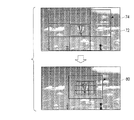
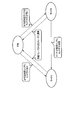
本実施形態に係る撮影装置1によるオートフォーカス(AF)動作の概略について、図2及び図3を参照して説明する。本実施形態に係る撮影装置1では、ユーザがAFによって合焦させたい領域を選択することができる。このユーザが選択した領域をAF可否判定エリア72と称することにする。また、いわゆるオールターゲットモードなどのように、ユーザによるAF領域選択がなく最至近選択等により自動的にAF領域を選択する場合にも、任意の1点をAF可否判定エリアとして扱うことができる。図2の上図は、撮影領域の中央がAF可否判定エリア72として選択されている場合を示す。また、本実施形態に係る撮影装置1では、図2の上図に示すように、撮影領域を覆うように9つの周辺エリア74が設けられている。
The outline of the autofocus (AF) operation by the photographing apparatus 1 according to the present embodiment will be described with reference to FIGS. In the photographing apparatus 1 according to the present embodiment, the user can select an area to be focused by AF. The area selected by the user will be referred to as an AF availability determination area 72. Also, when there is no AF area selection by the user and the AF area is automatically selected by the closest selection or the like as in the so-called all target mode, any one point can be handled as the AF availability determination area. The upper diagram of FIG. 2 shows a case where the center of the shooting area is selected as the AF availability determination area 72. Further, in the photographing apparatus 1 according to the present embodiment, nine peripheral areas 74 are provided so as to cover the photographing region as shown in the upper diagram of FIG.
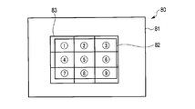
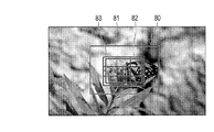
図2に示すように、AF可否判定エリア72にコントラストが高い被写体があるとき、すなわち、AF可否判定エリア72においてAFが容易であるとき、図2の下図に示すようにAF可否判定エリア72に、AF動作における解析が行われるAFエリアを複数含むAFエリア群80が設定される。このように、AF可否判定エリア72にAFエリア群80が設定される状態をモードAと称することにする。
As shown in FIG. 2, when there is a subject with high contrast in the AF feasibility judgment area 72, that is, when AF is easy in the AF feasibility judgment area 72, as shown in the lower diagram of FIG. Then, an AF area group 80 including a plurality of AF areas to be analyzed in the AF operation is set. A state in which the AF area group 80 is set in the AF availability determination area 72 in this way is referred to as mode A.
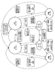
一方、図3の上から1番目の図に示すように、AF可否判定エリア72内のコントラストが低いとき、すなわち、AF可否判定エリア72においてAFが困難であるとき、図3の上から2番目の図に示すように、AF可否判定エリア72にはAFエリア群80は設定されず、9つの周辺エリア74のうち、コントラストが高い被写体があるエリアにAFエリア群80が設定される。図3の上から2番目の図では、右下の周辺エリア74にAFエリア群80が設定される。このとき、AF可否判定エリア72には、コントラストが高い被写体の出現を監視するターゲット監視エリア92が設定される。このように、AF可否判定エリア72にAFエリア群80が設定されない状態をモードBと称することにする。
On the other hand, as shown in the first diagram from the top of FIG. 3, when the contrast in the AF feasibility judgment area 72 is low, that is, when AF is difficult in the AF feasibility judgment area 72, the second from the top in FIG. As shown in the figure, the AF area group 80 is not set in the AF enable / disable determination area 72, and the AF area group 80 is set in an area where there is a subject with high contrast among the nine peripheral areas 74. In the second diagram from the top in FIG. 3, the AF area group 80 is set in the lower right peripheral area 74. At this time, a target monitoring area 92 for monitoring the appearance of a subject with high contrast is set in the AF availability determination area 72. A state where the AF area group 80 is not set in the AF availability determination area 72 is referred to as mode B.
このように、AF可否判定エリア72及びターゲット監視エリア92は、合焦状態の調整の対象となる領域である第1の焦点調整領域に対応し、周辺エリア74は、合焦状態の調整の対象となる領域であり第1の焦点調整領域よりも合焦の調整に係る優先度が低い第2の焦点調整領域に対応する。
As described above, the AF feasibility determination area 72 and the target monitoring area 92 correspond to the first focus adjustment area that is an area to be adjusted for the in-focus state, and the peripheral area 74 is the object to be adjusted for the in-focus state. This corresponds to a second focus adjustment region that has a lower priority for focus adjustment than the first focus adjustment region.
図3の上から3番目の図に示すように、ターゲット監視エリア92に、コントラストが高い被写体が出現したとき、図3の上から4番目の図に示すように、AFエリア群80は、ターゲット監視エリア92、すなわちAF可否判定エリア72に設定される。
As shown in the third diagram from the top in FIG. 3, when a subject with high contrast appears in the target monitoring area 92, the AF area group 80 displays the target as shown in the fourth diagram from the top in FIG. 3. It is set in the monitoring area 92, that is, the AF availability determination area 72.
本実施形態に係る撮影装置1では、AF動作のフェーズとして、3種類のフェーズが用いられる。すなわち、ウォブリングフェーズ(wob)と、サーチフェーズ(サーチ)と、待機フェーズ(待機)とが用いられる。
In the photographing apparatus 1 according to the present embodiment, three types of phases are used as AF operation phases. That is, a wobbling phase (wob), a search phase (search), and a standby phase (standby) are used.
ウォブリングフェーズにおいて行われるAF動作について図4及び図5を参照して説明する。ウォブリングフェーズでは、フォーカスレンズは、例えば1フレーム毎に無限遠方向と至近方向とに交互に微小駆動される。このような微小駆動を行いながら徐々に振幅の中心位置を移動させることで、フォーカスの微調整が行われたり、合焦位置の方向の判定が行われたりする。このようなフォーカスレンズの駆動をウォブリング駆動(ウォブリング動作)と称する。
AF operation performed in the wobbling phase will be described with reference to FIGS. In the wobbling phase, for example, the focus lens is minutely driven alternately in the infinity direction and the closest direction for each frame. By gradually moving the center position of the amplitude while performing such minute driving, fine adjustment of the focus is performed or the direction of the in-focus position is determined. Such driving of the focus lens is referred to as wobbling driving (wobbling operation).
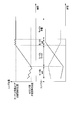
図4は、ウォブリング駆動による合焦位置の方向の判定方法を説明するための図である。図4において、実線は、時間経過に対するレンズ位置の変化を示し、破線は、レンズ位置に対して得られる画像のコントラスト値を示す。図4の実線に示すように、レンズ位置が無限遠方向と至近方向とに交互に移動するとき、コントラスト値の変化が得られる。このコントラスト値の変化に基づいて、合焦位置の方向が判定され得る。無限遠方向と至近方向とのうち、コントラスト値が高くなる方向が合焦位置の方向である。
FIG. 4 is a diagram for explaining a method of determining the direction of the in-focus position by wobbling driving. In FIG. 4, the solid line indicates the change in the lens position with time, and the broken line indicates the contrast value of the image obtained with respect to the lens position. As shown by the solid line in FIG. 4, when the lens position moves alternately in the infinity direction and the close-up direction, a change in contrast value is obtained. Based on the change in the contrast value, the direction of the in-focus position can be determined. Of the infinity direction and the closest direction, the direction in which the contrast value increases is the direction of the in-focus position.
レンズ位置の無限遠方向と至近方向との振幅量が大きいほど、コントラスト値の変化は検出されやすくなり、方向判断はされやすくなる。一方で、振幅量が大きいと、動画に記録されるフォーカスレンズの移動が視認されやすくなる。逆に、振幅量が小さいと、動画に記録されるフォーカスレンズの移動は視認されにくくなるが、コントラスト値の変化は検出されにくくなり、方向判断が難しくなる。本実施形態では、この振幅量は、被写体や撮影条件に応じて適宜に調整される。
The greater the amount of amplitude between the infinity direction and the close direction of the lens position, the easier it is to detect a change in the contrast value and the easier it is to determine the direction. On the other hand, when the amount of amplitude is large, the movement of the focus lens recorded in the moving image is easily visually recognized. On the other hand, when the amplitude is small, the movement of the focus lens recorded in the moving image becomes difficult to be visually recognized, but the change of the contrast value becomes difficult to detect and the direction determination becomes difficult. In the present embodiment, the amount of amplitude is appropriately adjusted according to the subject and shooting conditions.
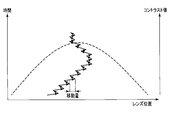
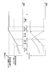
図5は、ウォブリング駆動によるフォーカスの微調整の方法を説明するための図である。図5において、実線は、時間経過に対するレンズ位置の変化を示し、破線は、レンズ位置に対して得られる画像のコントラスト値の変化を示す。フォーカスの微調整を行うとき、図5に示すように、無限遠方向と至近方向とに移動させるレンズ位置の振幅の中心位置は徐々に移動する。この移動は、取得されたコントラスト値の情報に基づいて、コントラスト値が最高となるように行われる。この移動によって、フォーカスは、微調整される。この移動量が大きいほど、早く合焦するが、動画に記録される不要なフォーカスレンズの移動が生じやすくなる。逆にこの移動量が小さいほど、合焦までに時間がかかるが、動画に記録される不要なフォーカスレンズの移動が生じにくくなる。
FIG. 5 is a diagram for explaining a method of finely adjusting the focus by wobbling driving. In FIG. 5, the solid line indicates the change in the lens position with time, and the broken line indicates the change in the contrast value of the image obtained with respect to the lens position. When performing fine adjustment of the focus, as shown in FIG. 5, the center position of the amplitude of the lens position to be moved in the infinity direction and the close direction gradually moves. This movement is performed based on the acquired contrast value information so that the contrast value becomes maximum. By this movement, the focus is finely adjusted. The larger the amount of movement, the faster the focus is achieved, but an unnecessary movement of the focus lens recorded in the moving image is likely to occur. Conversely, the smaller the amount of movement, the longer it takes to focus, but it becomes difficult for unnecessary focus lens movement recorded in the moving image to occur.
サーチフェーズにおいて行われるAF動作について図6を参照して説明する。図6において、実線は、時間経過に対するレンズ位置の変化を示し、破線は、レンズ位置に対して得られる画像のコントラスト値の変化を示す。サーチフェーズでは、フォーカスレンズは、一方向に連続的に移動する。このようなフォーカスレンズの駆動をスキャン駆動(スキャン動作)と称する。フォーカスレンズがスキャン駆動されているとき、その合焦状態に応じてコントラスト値は変化する。スキャン駆動によっても、合焦位置が探索され得る。また、スキャン駆動によるフォーカスレンズの移動は、ウォブリング駆動によるフォーカスレンズの移動よりも早い。
The AF operation performed in the search phase will be described with reference to FIG. In FIG. 6, a solid line indicates a change in the lens position with time, and a broken line indicates a change in the contrast value of the image obtained with respect to the lens position. In the search phase, the focus lens moves continuously in one direction. Such driving of the focus lens is referred to as scan driving (scanning operation). When the focus lens is driven to scan, the contrast value changes according to the in-focus state. The in-focus position can also be searched by scan driving. Further, the movement of the focus lens by scan driving is faster than the movement of the focus lens by wobbling driving.
次に制御フェーズの遷移について、図7を参照して説明する。前述のとおり、本実施形態に係る制御フェーズには、ウォブリングフェーズ(wob)と、サーチフェーズ(サーチ)と、待機フェーズ(待機)とがある。動画記録開始時は、wobから制御が開始される。wobでは、フォーカスレンズのレンズ位置が合焦位置から遠いと判断されたとき、すなわち、コントラスト値のピークが遠いと判断されたとき、サーチに遷移する。サーチに遷移することによって、レンズ位置は素早く合焦位置へと移動する。一方、wobにおいて、レンズ位置は既に合焦位置だと判断されたとき、待機に遷移し、レンズ駆動を止める。
Next, the transition of the control phase will be described with reference to FIG. As described above, the control phase according to the present embodiment includes the wobbling phase (wob), the search phase (search), and the standby phase (standby). At the start of moving image recording, control starts from web. In wob, when it is determined that the lens position of the focus lens is far from the in-focus position, that is, when it is determined that the peak of the contrast value is far, a transition is made to search. By shifting to the search, the lens position quickly moves to the in-focus position. On the other hand, when it is determined that the lens position is already the in-focus position in wob, the process shifts to standby and stops lens driving.
サーチでは、レンズ位置が合焦位置に到達したとき、すなわち、コントラスト値がピークだと判断されたとき、wobに遷移する。このとき、ウォブリング駆動によって、合焦状態が維持される。一方、サーチにおいて、安定した条件で合焦しているとき、すなわち、コントラスト値がピークに到達して安定した状態にあると判断されたとき、待機に遷移し、レンズ駆動を止める。
In the search, when the lens position reaches the in-focus position, that is, when it is determined that the contrast value is a peak, the state transitions to web. At this time, the focused state is maintained by the wobbling drive. On the other hand, in the search, when focusing is performed under a stable condition, that is, when it is determined that the contrast value reaches a peak and is in a stable state, the state is shifted to standby and the lens driving is stopped.
待機では、ジャイロによる撮影装置1の動きの検出があったときや、画像におけるコントラスト値の変化や顔情報の変化などがあったと判断されたときは、wobに遷移し、合焦状態を維持するようにウォブリング動作を再開する。
In standby mode, when the movement of the photographing apparatus 1 is detected by the gyro, or when it is determined that there is a change in contrast value or face information in the image, the process shifts to web and maintains the in-focus state. Resume wobbling.
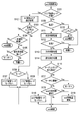
次に、wobフェーズ、サーチフェーズ、待機フェーズにおける動作について、フローチャートを参照して説明する。動画AFは、wobフェーズから開始する。まず、wobフェーズにおけるwob制御処理の動作の一例を図8のフローチャートを参照して説明する。
Next, operations in the web phase, the search phase, and the standby phase will be described with reference to flowcharts. The moving image AF starts from the web phase. First, an example of the operation of the web control process in the web phase will be described with reference to the flowchart of FIG.
ステップS101において、システムコントローラ10は、エリア配置モードが不明であるか否かを判定する。ここで、エリア配置モードとは、前述のとおり、AF可否判定エリア72にAFエリア群80が設定されているモードAと、周辺エリア74の何れかにAFエリア群80が設定されているモードBとがある。動画AF開始時と待機フェーズからwobフェーズに遷移したときとは、エリア配置モードは不明となる。このとき、エリア配置は、仮にモードAと同様に設定される。エリア配置モードが不明であるとき、処理はステップS102に進む。
In step S101, the system controller 10 determines whether or not the area arrangement mode is unknown. Here, as described above, the area arrangement mode is the mode A in which the AF area group 80 is set in the AF availability determination area 72 and the mode B in which the AF area group 80 is set in any of the peripheral areas 74. There is. The area arrangement mode is unknown when the moving image AF starts and when the transition from the standby phase to the web phase occurs. At this time, the area arrangement is set in the same manner as in mode A. When the area arrangement mode is unknown, the process proceeds to step S102.
ステップS102において、システムコントローラ10は、AF実施エリア選択処理を行い、エリア配置モードをモードA又はモードBに設定する。AF実施エリア選択処理は、AF可否判定エリア72にコントラストがあるか否かを判定し、AF可否判定エリア72のコントラストが低いと判定される場合には、周辺エリア74のうち最もコントラストが高いエリアを選択する処理である。AF実施エリア選択処理について、図9に示すフローチャートを参照して説明する。
In step S102, the system controller 10 performs AF execution area selection processing, and sets the area arrangement mode to mode A or mode B. In the AF execution area selection process, it is determined whether or not the AF availability determination area 72 has a contrast. If it is determined that the contrast of the AF availability determination area 72 is low, the area having the highest contrast among the peripheral areas 74. Is the process of selecting. The AF execution area selection process will be described with reference to the flowchart shown in FIG.
ステップS201において、システムコントローラ10は、装着しているレンズの被写界深度が浅いか否かを判定する。被写界深度が浅いとき、処理はステップS202に進む。ステップS202において、システムコントローラ10は、AF実施可否判定閾値を低い値に設定する。その後、処理はステップS204に進む。ステップS201において、被写界深度が浅くないと判定されたとき、処理はステップS203に進む。ステップS203において、システムコントローラ10は、AF実施可否判定閾値を高い値に設定する。その後、処理はステップS204に進む。このようにして、装着しているレンズの被写界深度が浅いときには、周辺エリア74を用いるモードBが選択されにくく、AF可否判定エリア72を用いるモードAが選択されやすいように設定がなされる。なお、被写界深度の代わりに焦点深度やF値を用いてもよい。装着しているレンズが交換レンズである場合には、システムコントローラ10は、交換レンズとの通信により焦点深度(被写界深度)やF値を取得する。
In step S201, the system controller 10 determines whether or not the depth of field of the attached lens is shallow. When the depth of field is shallow, the process proceeds to step S202. In step S202, the system controller 10 sets the AF performance determination threshold value to a low value. Thereafter, the process proceeds to step S204. If it is determined in step S201 that the depth of field is not shallow, the process proceeds to step S203. In step S <b> 203, the system controller 10 sets the AF performance determination threshold value to a high value. Thereafter, the process proceeds to step S204. In this way, when the depth of field of the attached lens is shallow, the mode B using the peripheral area 74 is difficult to be selected, and the mode A using the AF feasibility determination area 72 is easily selected. . Note that the depth of focus and the F value may be used instead of the depth of field. When the attached lens is an interchangeable lens, the system controller 10 acquires the depth of focus (depth of field) and the F value by communicating with the interchangeable lens.
ステップS204において、システムコントローラ10は、ジャイロセンサ回路28からジャイロ出力情報を取得し、ジャイロ出力が安定しているか否かを判定する。ジャイロ出力が安定していないとき、処理はステップS205に進む。ステップS205において、システムコントローラ10は、ジャイロ安定カウンタ(以下ジャイロカウンタ)をクリアする。その後、処理はステップS206に進む。
In step S204, the system controller 10 acquires gyro output information from the gyro sensor circuit 28, and determines whether or not the gyro output is stable. When the gyro output is not stable, the process proceeds to step S205. In step S205, the system controller 10 clears a gyro stabilization counter (hereinafter referred to as a gyro counter). Thereafter, the process proceeds to step S206.
ステップS206において、システムコントローラ10は、エリア配置モードは不明であると判定し、エリア配置モードをそのまま維持する。すなわち、エリア配置モードは、仮に設定されたモードAで維持される。その後、AF実施エリア選択処理は終了し、処理はwob制御処理に戻る。
In step S206, the system controller 10 determines that the area arrangement mode is unknown, and maintains the area arrangement mode as it is. That is, the area arrangement mode is maintained in the temporarily set mode A. Thereafter, the AF execution area selection process ends, and the process returns to the web control process.
ステップS204において、ジャイロ出力が安定していると判定されたとき、処理はステップS207に進む。ステップS207において、システムコントローラ10は、ジャイロカウンタの値を増加させる。
When it is determined in step S204 that the gyro output is stable, the process proceeds to step S207. In step S207, the system controller 10 increases the value of the gyro counter.
ステップS208において、システムコントローラ10は、AF実施エリア選択処理の実施条件を満たしているか否かを判定する。例えば、次のときはAF実施エリア選択処理が行われないものと設定されている。すなわち、被写体が点光源であるとき、画像に含まれる顔を検出する顔検出処理を行い顔が検出できているとき、画像の中央部を切り出して拡大するいわゆるデジタルテレコンやムービーテレコンを行っているとき、又は画像中で被写体の追尾を行っているときには、AF実施エリア選択処理は行われない。AF実施エリア選択処理の実施の条件を満たしていないとき、すなわち、上述のようなAF実施エリア選択処理を実施しない状態にあるとき、処理はステップS206に進む。一方、AF実施エリア選択処理の実施の条件を満たしているとき、処理はステップS209に進む。
In step S208, the system controller 10 determines whether or not the execution conditions for the AF execution area selection process are satisfied. For example, it is set that the AF execution area selection process is not performed in the following cases. In other words, when the subject is a point light source, face detection processing is performed to detect the face included in the image, and when the face is detected, so-called digital telecon and movie telecon are performed to cut out and enlarge the center of the image. When the subject is being tracked in the image, the AF execution area selection process is not performed. When the conditions for performing the AF execution area selection process are not satisfied, that is, when the AF execution area selection process as described above is not performed, the process proceeds to step S206. On the other hand, when the conditions for performing the AF execution area selection process are satisfied, the process proceeds to step S209.
ステップS209において、システムコントローラ10は、ジャイロカウンタが所定の閾値よりも大きいか否か、すなわち、ジャイロが安定して所定の期間よりも長い期間が経過しているか否かを判定する。ジャイロカウンタが閾値よりも大きくないとき、処理はステップS206に進む。一方、ジャイロカウンタが閾値よりも大きいとき、処理はステップS210に進む。
In step S209, the system controller 10 determines whether or not the gyro counter is larger than a predetermined threshold, that is, whether or not a period longer than the predetermined period has elapsed since the gyro is stable. When the gyro counter is not greater than the threshold value, the process proceeds to step S206. On the other hand, when the gyro counter is larger than the threshold value, the process proceeds to step S210.
ステップS210において、システムコントローラ10は、AF可否判定エリア72でAFが可能か否かを判定する。例えば、AF可否判定エリア72のAF評価値がステップS202又はステップS203で設定されたAF実施可否判定閾値よりも大きいとき、AFが可能であると判定される。AF可否判定エリア72でAFが可能であるとき、処理はステップS211に進む。
In step S210, the system controller 10 determines whether or not AF is possible in the AF availability determination area 72. For example, when the AF evaluation value in the AF feasibility judgment area 72 is larger than the AF feasibility judgment threshold set in step S202 or step S203, it is judged that AF is possible. When AF is possible in the AF availability determination area 72, the process proceeds to step S211.
ステップS211において、システムコントローラ10は、エリア配置モードはモードAであると確定する。すなわち、仮に設定されたモードAのエリア配置が維持される。その後、AF実施エリア選択処理は終了し、処理はwob制御処理に戻る。
In step S211, the system controller 10 determines that the area arrangement mode is mode A. That is, the temporarily set mode A area arrangement is maintained. Thereafter, the AF execution area selection process ends, and the process returns to the web control process.
ステップS210において、AF可否判定エリア72でAFが可能でないと判定されたとき、処理はステップS212に進む。ステップS212において、システムコントローラ10は、周辺エリア74にコントラストの高い領域があるか否かを判定する。例えば、周辺エリア74のうち何れかのエリアのAF評価値が所定の閾値よりも大きいとき、周辺エリア74にコントラストの高い領域があると判定される。コントラストの高い領域があると判定されたとき、処理はステップS213に進む。
In step S210, when it is determined in the AF availability determination area 72 that AF is not possible, the process proceeds to step S212. In step S212, the system controller 10 determines whether or not there is a high contrast area in the peripheral area 74. For example, when the AF evaluation value in any one of the peripheral areas 74 is larger than a predetermined threshold, it is determined that there is a high contrast area in the peripheral area 74. When it is determined that there is a region with high contrast, the process proceeds to step S213.
ステップS213において、システムコントローラ10は、エリア配置モードはモードBであると確定する。その後、AF実施エリア選択処理は終了し、処理はwob制御処理に戻る。
In step S213, the system controller 10 determines that the area arrangement mode is mode B. Thereafter, the AF execution area selection process ends, and the process returns to the web control process.
ステップS212において、周辺エリア74にコントラストの高い領域がないと判定されたとき、処理はステップS214に進む。ステップS214において、システムコントローラ10は、ジャイロが安定してから所定フレームが経過したか否かを判定する。所定フレーム経過していないと判定されたとき、処理はステップS215に進む。
When it is determined in step S212 that there is no high contrast area in the peripheral area 74, the process proceeds to step S214. In step S214, the system controller 10 determines whether a predetermined frame has elapsed after the gyro is stabilized. When it is determined that the predetermined frame has not elapsed, the process proceeds to step S215.
ステップS215において、システムコントローラ10は、エリア配置モードは不明であると判定し、エリア配置モードをそのまま維持する。すなわち、エリア配置は、仮に設定されたモードAのエリア配置で維持される。その後、AF実施エリア選択処理は終了し、処理はwob制御処理に戻り、次のフレームで再度、AF実施エリア選択処理を実施する。
In step S215, the system controller 10 determines that the area arrangement mode is unknown, and maintains the area arrangement mode as it is. That is, the area arrangement is maintained in the mode A area arrangement that is temporarily set. Thereafter, the AF execution area selection process ends, the process returns to the web control process, and the AF execution area selection process is performed again in the next frame.
ステップS214において、ジャイロが安定してから所定フレームが経過したと判定されたとき、処理はステップS216に進む。ステップS216において、システムコントローラ10は、被写界深度が浅いか否かを判定する。被写界深度が浅いとき、フォーカスのずれが非常に大きく、ぼけが大きいときであると考えらえる。このとき、処理は、後述するサーチ制御処理に遷移する。一方、被写界深度が浅くないと判定されたとき、被写体全体でコントラストが低いと考えられる。このとき、処理は、後述する待機制御処理に遷移する。
In step S214, when it is determined that the predetermined frame has elapsed after the gyro is stabilized, the process proceeds to step S216. In step S216, the system controller 10 determines whether or not the depth of field is shallow. When the depth of field is shallow, it can be considered that the focus shift is very large and the blur is large. At this time, the process transitions to a search control process described later. On the other hand, when it is determined that the depth of field is not shallow, it is considered that the contrast of the entire subject is low. At this time, the process transitions to a standby control process described later.
図8に戻って、wob制御処理について説明を続ける。ステップS102のAF実施エリア選択処理の後、処理はステップS103に進む。
Referring back to FIG. 8, the description of the web control process will be continued. After the AF execution area selection process in step S102, the process proceeds to step S103.
ステップS103において、システムコントローラ10は、撮影領域全面においてコントラストが低いか否かを判定する。全面においてコントラストが低いとき、処理はステップS104に進む。ステップS104において、システムコントローラ10は、所定の一定期間が経過したか否かを判定する。経過していないとき、wob制御処理を継続する。すなわち、処理はステップS101に戻る。一方、所定期間が経過したとき、処理はステップS105に進む。
In step S103, the system controller 10 determines whether or not the contrast is low over the entire imaging area. When the contrast is low on the entire surface, the process proceeds to step S104. In step S104, the system controller 10 determines whether or not a predetermined period has elapsed. When the time has not elapsed, the web control process is continued. That is, the process returns to step S101. On the other hand, when the predetermined period has elapsed, the process proceeds to step S105.
ステップS105において、システムコントローラ10は、被写界深度が浅いか否かを判定する。被写界深度が浅いとき、フォーカスのずれが非常に大きいときであると考えられるので、処理はサーチ制御処理へと遷移する。一方、被写界深度が浅くないとき、被写体全体でコントラストが低いと考えられるので、処理は待機制御処理へと遷移する。
In step S105, the system controller 10 determines whether or not the depth of field is shallow. When the depth of field is shallow, it is considered that the focus shift is very large. Therefore, the process shifts to the search control process. On the other hand, when the depth of field is not shallow, it is considered that the contrast of the entire subject is low, and therefore the process shifts to the standby control process.
ステップS103において、撮影領域全面ではコントラストが低くないと判定されたとき、処理はステップS106に進む。ステップS106において、システムコントローラ10は、AF実施エリア選択処理で選択されたエリア配置モードがモードAであるかモードBであるかを判定する。モードAであるとき、処理はステップS107に進む。一方、モードBであるとき、処理はステップS108に進む。
In step S103, when it is determined that the contrast is not low over the entire imaging region, the process proceeds to step S106. In step S106, the system controller 10 determines whether the area arrangement mode selected in the AF execution area selection processing is mode A or mode B. When in mode A, the process proceeds to step S107. On the other hand, when the mode is B, the process proceeds to step S108.
ステップS107において、システムコントローラ10は、エリア配置モードをモードAとし、AFエリア群80をAF可否判定エリア72に設定する。その後、wob制御処理を継続する。すなわち、処理はステップS101に戻る。
In step S107, the system controller 10 sets the area arrangement mode to mode A, and sets the AF area group 80 to the AF availability determination area 72. Thereafter, the web control process is continued. That is, the process returns to step S101.
ステップS108において、システムコントローラ10は、エリア配置モードをモードBとし、AFエリア群80をコントラストが高い周辺エリア74に設定する。その後、wob制御処理を継続する。すなわち、処理はステップS101に戻る。
In step S108, the system controller 10 sets the area arrangement mode to mode B, and sets the AF area group 80 to the peripheral area 74 with high contrast. Thereafter, the web control process is continued. That is, the process returns to step S101.
ステップS101において、エリア配置モードが不明でないと判定されたとき、処理はステップS109に進む。ステップS109において、システムコントローラ10は、フォーカスレンズのレンズ位置が端点にあるか否かを判定する。端点にあるとき、処理はステップS110に進む。ステップS110において、システムコントローラ10は、リトライするか否かを判定する。ここでリトライとは、ウォブリング駆動によって合焦状態にするための動作を継続することをいう。リトライするとき、wob制御処理を継続する。すなわち、処理はステップS101に戻る。一方、リトライしないとき、処理は待機制御処理に遷移する。
When it is determined in step S101 that the area arrangement mode is not unknown, the process proceeds to step S109. In step S109, the system controller 10 determines whether or not the lens position of the focus lens is at the end point. When it is at the end point, the process proceeds to step S110. In step S110, the system controller 10 determines whether to retry. Here, “retry” means to continue the operation for achieving the in-focus state by the wobbling drive. When retrying, the web control process is continued. That is, the process returns to step S101. On the other hand, when not retrying, the process transitions to a standby control process.
ステップS109において、レンズ位置は端点でないと判定されたとき、処理はステップS111に進む。ステップS111において、システムコントローラ10は、合焦判断処理を実行する。合焦判断処理は、ウォブリング駆動の駆動状況と、コントラスト値の変化から、現在、合焦状態であるかを判断する処理である。
If it is determined in step S109 that the lens position is not an end point, the process proceeds to step S111. In step S111, the system controller 10 executes an in-focus determination process. The in-focus determination process is a process for determining whether or not the in-focus state is present from the driving state of wobbling driving and a change in contrast value.
ステップS112において、システムコントローラ10は、合焦状態であるか否かを判定する。合焦状態であるとき、処理は待機制御処理に遷移する。一方、合焦状態でないとき、処理はステップS113に進む。
In step S112, the system controller 10 determines whether or not it is in focus. When in the in-focus state, the process transitions to a standby control process. On the other hand, when not in focus, the process proceeds to step S113.
ステップS113において、システムコントローラ10は、方向判断処理を行う。方向判断処理では、合焦位置の方向と合焦位置までの距離とに係る情報が取得される。
In step S113, the system controller 10 performs direction determination processing. In the direction determination process, information related to the direction of the in-focus position and the distance to the in-focus position is acquired.
ステップS114において、システムコントローラ10は、変化検出処理を行う。変化検出処理は、エリア配置モードがモードBであるときに行われる。変化検出処理は、モードBにおけるAF可否判定エリア72であるターゲット監視エリア92にコントラストが高い被写体が現れることを監視する処理であり、ターゲット監視エリア92内のコントラストの評価値の増加又は減少を監視する処理である。変化検出処理について説明する。
In step S114, the system controller 10 performs a change detection process. The change detection process is performed when the area arrangement mode is mode B. The change detection process is a process for monitoring the appearance of a subject with high contrast in the target monitoring area 92 that is the AF feasibility determination area 72 in mode B, and monitors the increase or decrease in the contrast evaluation value in the target monitoring area 92. It is processing to do. The change detection process will be described.
変化検出処理では、例えば3種類の閾値が用いられる。この3種類の閾値を、第1の閾値、第2の閾値及び第3の閾値とする。例えば第1の閾値では、ターゲット監視エリア92におけるコントラスト値が変化したか否かの判定基準となる変化率の閾値が30%に設定されており、その変化が継続している期間を表す継続時間の閾値が20フレームに設定されている。すなわち、コントラスト値の変化率が30%以上であり、そのコントラスト値が20フレーム以上継続したときに、変化があったと検出されることになる。第2の閾値では、変化率の閾値が32%に設定されており、継続時間の閾値が12フレームに設定されている。第3の閾値では、変化率の閾値が35%に設定されており、継続時間の閾値が10フレームに設定されている。第1乃至第3の閾値の何れかの条件を満たすとき、ターゲット監視エリア92にコントラストが高い被写体が出現したと判定される。
In the change detection process, for example, three types of threshold values are used. These three types of threshold values are a first threshold value, a second threshold value, and a third threshold value. For example, in the first threshold value, the threshold value of the change rate that is a criterion for determining whether or not the contrast value in the target monitoring area 92 has changed is set to 30%, and the duration time that represents the period during which the change continues. Is set to 20 frames. That is, when the contrast value change rate is 30% or more and the contrast value continues for 20 frames or more, it is detected that there is a change. In the second threshold, the threshold of change rate is set to 32%, and the threshold of duration is set to 12 frames. In the third threshold, the change rate threshold is set to 35%, and the duration threshold is set to 10 frames. When any one of the first to third threshold values is satisfied, it is determined that a subject with high contrast has appeared in the target monitoring area 92.
なお、第1乃至第3の閾値は、ターゲット監視エリア92におけるコントラストの検出に用いられるハイパスフィルタの強度(周波数特性)によって異なるように設定され得る。例えば上述の場合と異なる強度のハイパスフィルタが用いられるとき、例えば第1の閾値では、変化率の閾値が32%に設定され、継続時間の閾値が20フレームに設定される。また、第2の閾値では、変化率の閾値が35%に設定され、継続時間の閾値が12フレームに設定される。第3の閾値では、変化率の閾値が38%に設定され、継続時間の閾値が10フレームに設定される。
Note that the first to third threshold values can be set differently depending on the strength (frequency characteristic) of the high-pass filter used for detecting the contrast in the target monitoring area 92. For example, when a high-pass filter having a strength different from that described above is used, for example, in the first threshold, the threshold of change rate is set to 32%, and the threshold of duration is set to 20 frames. In the second threshold, the threshold of change rate is set to 35%, and the threshold of duration is set to 12 frames. In the third threshold, the change rate threshold is set to 38%, and the duration threshold is set to 10 frames.
変化検出処理について、図10に示すフローチャートを参照して説明する。ステップS301において、システムコントローラ10は、ターゲット監視エリア92における増加方向のコントラスト変化が第1の閾値よりも大きいか否かを判定する。第1の閾値よりも大きいとき、処理はステップS302に進む。
The change detection process will be described with reference to the flowchart shown in FIG. In step S301, the system controller 10 determines whether or not the increasing contrast change in the target monitoring area 92 is greater than the first threshold value. When it is larger than the first threshold value, the process proceeds to step S302.
ステップS302において、システムコントローラ10は、増加方向の変化検出カウント処理を行う。増加方向の変化検出カウント処理は、上述の第1乃至第3の閾値の何れかの条件を満たしているか否かを判定する処理である。本処理のため、第1乃至第3の閾値用の増加方向のカウンタと、第1乃至第3の閾値用の減少方向のカウンタとの合計6つの変数が用意されている。増加方向の変化検出カウント処理について、図11を参照して説明する。
In step S302, the system controller 10 performs an increase direction change detection count process. The increase direction change detection count process is a process for determining whether or not any of the above-described first to third threshold values is satisfied. For this processing, a total of six variables are prepared: a counter in the increasing direction for the first to third threshold values and a counter in the decreasing direction for the first to third threshold values. The increase direction change detection count processing will be described with reference to FIG.
ステップS401において、システムコントローラ10は、第1乃至第3の閾値用の減少方向のカウンタの値を全てクリアして0とする。ステップS402において、システムコントローラ10は、第1の閾値用の増加方向カウンタを増加させる。
In step S401, the system controller 10 clears all the counter values in the decreasing direction for the first to third thresholds to zero. In step S402, the system controller 10 increments the increase direction counter for the first threshold.
ステップS403において、システムコントローラ10は、第1の閾値用の増加方向のカウンタの値が第1の閾値の継続時間の閾値よりも大きいか否かを判定する。第1の閾値用のカウンタの値が閾値よりも大きいとき、処理はステップS404に進む。ステップS404において、システムコントローラ10は、ターゲット監視エリア92における変化を検出した旨を設定する。その後、本処理を終了し、処理は変化検出処理に戻る。
In step S403, the system controller 10 determines whether or not the value of the increasing counter for the first threshold value is greater than the threshold value for the duration of the first threshold value. When the value of the first threshold counter is larger than the threshold, the process proceeds to step S404. In step S404, the system controller 10 sets that a change in the target monitoring area 92 has been detected. Thereafter, this process is terminated, and the process returns to the change detection process.
ステップS403において、第1の閾値用のカウンタの値が閾値よりも大きくないと判定されたとき、処理はステップS405に進む。ステップS405において、システムコントローラ10は、ターゲット監視エリア92における増加方向のコントラスト変化が第2の閾値よりも大きいか否かを判定する。第2の閾値よりも大きいとき、処理はステップS406に進む。
If it is determined in step S403 that the value of the first threshold counter is not greater than the threshold, the process proceeds to step S405. In step S405, the system controller 10 determines whether or not the increase in contrast in the target monitoring area 92 is greater than the second threshold value. When it is larger than the second threshold value, the process proceeds to step S406.
ステップS406において、システムコントローラ10は、第2の閾値用の増加方向カウンタを増加させる。ステップS407において、システムコントローラ10は、第2の閾値用の増加方向のカウンタの値が第2の閾値の継続時間の閾値よりも大きいか否かを判定する。第2の閾値用のカウンタの値が閾値よりも大きいとき、処理はステップS404に進む。一方、第2の閾値用のカウンタの値が閾値よりも大きくないとき、処理はステップS408に進む。
In step S406, the system controller 10 increments the increase direction counter for the second threshold. In step S407, the system controller 10 determines whether or not the value of the increasing counter for the second threshold value is greater than the threshold value for the duration of the second threshold value. When the value of the second threshold counter is larger than the threshold, the process proceeds to step S404. On the other hand, when the value of the second threshold counter is not greater than the threshold, the process proceeds to step S408.
ステップS408において、システムコントローラ10は、ターゲット監視エリア92における増加方向のコントラスト変化が第3の閾値よりも大きいか否かを判定する。第3の閾値よりも大きいとき、処理はステップS409に進む。ステップS409において、システムコントローラ10は、第3の閾値用の増加方向カウンタを増加させる。ステップS410において、システムコントローラ10は、第3の閾値用の増加方向のカウンタの値が第3の閾値の継続時間の閾値よりも大きいか否かを判定する。第3の閾値用のカウンタの値が閾値よりも大きいとき、処理はステップS404に進む。一方、第3の閾値用のカウンタの値が閾値よりも大きくないとき、本処理は終了し、処理は変化検出処理に戻る。
In step S408, the system controller 10 determines whether or not the increase in contrast in the target monitoring area 92 is greater than the third threshold value. When it is larger than the third threshold value, the process proceeds to step S409. In step S409, the system controller 10 increments the increase direction counter for the third threshold value. In step S410, the system controller 10 determines whether or not the value of the increasing counter for the third threshold value is greater than the threshold value for the duration of the third threshold value. When the value of the third threshold counter is larger than the threshold, the process proceeds to step S404. On the other hand, when the value of the counter for the third threshold value is not larger than the threshold value, this process ends and the process returns to the change detection process.
ステップS408において、ターゲット監視エリア92における増加方向のコントラスト変化が第3の閾値よりも大きくないと判定されたとき、処理はステップS411に進む。ステップS411において、システムコントローラ10は、第3の閾値用の増加方向カウンタをクリアする。その後、本処理は終了し、処理は変化検出処理に戻る。
In step S408, when it is determined that the contrast change in the increasing direction in the target monitoring area 92 is not larger than the third threshold value, the process proceeds to step S411. In step S411, the system controller 10 clears the increase direction counter for the third threshold value. Thereafter, this process ends, and the process returns to the change detection process.
ステップS405において、ターゲット監視エリア92における増加方向のコントラスト変化が第2の閾値よりも大きくないと判定されたとき、処理はステップS412に進む。ステップS412において、システムコントローラ10は、第2の閾値用の増加方向カウンタ及び第3の閾値用の増加方向カウンタをクリアする。その後、本処理は終了し、処理は変化検出処理に戻る。
If it is determined in step S405 that the contrast change in the increasing direction in the target monitoring area 92 is not greater than the second threshold value, the process proceeds to step S412. In step S412, the system controller 10 clears the increase direction counter for the second threshold and the increase direction counter for the third threshold. Thereafter, this process ends, and the process returns to the change detection process.
図10に戻って、変化検出処理について説明を続ける。ステップS302の増加方向の変化検出カウント処理の後、変化検出処理は終了し、処理はwob制御処理に戻る。
Referring back to FIG. 10, the description of the change detection process will be continued. After the change detection count process in the increasing direction in step S302, the change detection process ends, and the process returns to the web control process.
ステップS301において、ターゲット監視エリア92における増加方向のコントラスト変化が第1の閾値よりも大きくないと判定されたとき、処理はステップS303に進む。
When it is determined in step S301 that the increase in contrast in the target monitoring area 92 is not greater than the first threshold, the process proceeds to step S303.
ステップS303において、システムコントローラ10は、ターゲット監視エリア92における減少方向のコントラスト変化が第1の閾値よりも大きいか否かを判定する。第1の閾値よりも大きいとき、処理はステップS304に進む。
In step S303, the system controller 10 determines whether or not the contrast change in the decreasing direction in the target monitoring area 92 is larger than the first threshold value. When it is larger than the first threshold, the process proceeds to step S304.
ステップS304において、システムコントローラ10は、減少方向の変化検出カウント処理を行う。減少方向の変化検出カウント処理は、上述の第1乃至第3の閾値の何れかの条件を満たしているか否かを判定する処理である。減少方向の変化検出カウント処理は、増加であるか減少であるかの違いを除いて、図11を参照して説明した減少方向の変化検出カウント処理と同様であるので、その説明を省略する。減少方向の変化検出カウント処理の後、変化検出処理は終了し、処理はwob制御処理に戻る。
In step S304, the system controller 10 performs a change detection count process in the decreasing direction. The change detection count process in the decreasing direction is a process for determining whether or not any of the above-described first to third threshold values is satisfied. The change detection count process in the decreasing direction is the same as the change detection count process in the decreasing direction described with reference to FIG. 11 except for the difference between increase and decrease, and thus the description thereof is omitted. After the change detection count process in the decreasing direction, the change detection process ends, and the process returns to the web control process.
ステップS303において、ターゲット監視エリア92における減少方向のコントラスト変化が第1の閾値よりも大きくないと判定されたとき、処理はステップS305に進む。ステップS305において、システムコントローラ10は、第1乃至第3の閾値用の増加方向カウンタ及び減少方向カウンタの全てをクリアする変化検出カウンタ初期化処理を行う。その後、変化検出処理は終了し、処理はwob制御処理に戻る。
In step S303, when it is determined that the contrast change in the decreasing direction in the target monitoring area 92 is not larger than the first threshold value, the process proceeds to step S305. In step S305, the system controller 10 performs a change detection counter initialization process that clears all of the increase direction counter and the decrease direction counter for the first to third threshold values. Thereafter, the change detection process ends, and the process returns to the web control process.
図8に戻ってwob制御処理について説明を続ける。ステップS114の変化検出処理の後、処理はステップS115に進む。ステップS115において、システムコントローラ10は、変化検出処理によってターゲット監視エリア92において変化が検出されたか否かを判定する。変化が検出されたとき、処理はステップS116に進む。ステップS116において、システムコントローラ10は、エリア配置モードをモードAとし、AFエリア群80をAF可否判定エリア72に設定する。その後、wob制御処理を継続する。すなわち、処理はステップS101に戻る。その結果、AF可否判定エリア72で合焦するように焦点調整が行われることになる。
Referring back to FIG. 8, the description of the web control process will be continued. After the change detection process in step S114, the process proceeds to step S115. In step S115, the system controller 10 determines whether or not a change is detected in the target monitoring area 92 by the change detection process. When a change is detected, the process proceeds to step S116. In step S <b> 116, the system controller 10 sets the area arrangement mode to mode A, and sets the AF area group 80 as the AF availability determination area 72. Thereafter, the web control process is continued. That is, the process returns to step S101. As a result, focus adjustment is performed so as to focus on the AF availability determination area 72.
ステップS115において、変化検出処理によってターゲット監視エリア92において変化が検出されていないと判定されたとき、処理はステップS117に進む。ステップS117において、システムコントローラ10は、処理をサーチフェーズに遷移させるか否かを判定する。例えば合焦位置が所定の値よりも遠いと判断されるとき、サーチフェーズに遷移させると判定する。サーチフェーズに遷移させると判定されたとき、処理はサーチ制御処理に遷移する。一方、サーチフェーズに遷移させないと判定されたとき、処理はステップS118に進む。
In step S115, when it is determined by the change detection process that no change is detected in the target monitoring area 92, the process proceeds to step S117. In step S117, the system controller 10 determines whether or not to shift the process to the search phase. For example, when it is determined that the in-focus position is farther than a predetermined value, it is determined to shift to the search phase. When it is determined to shift to the search phase, the process shifts to the search control process. On the other hand, when it is determined not to shift to the search phase, the process proceeds to step S118.
ステップS118において、システムコントローラ10は、ウォブリング駆動において、方向判断が確定しているか否か、すなわち、フォーカスレンズを移動させる方向が確定しているか否かを判定する。方向判断が確定していないとき、wob制御処理を継続する。すなわち、処理はステップS101に戻る。一方、方向判断が確定しているとき、処理はステップS119に進む。
In step S118, the system controller 10 determines whether or not the direction determination is determined in wobbling driving, that is, whether or not the direction in which the focus lens is moved is determined. When the direction determination is not fixed, the web control process is continued. That is, the process returns to step S101. On the other hand, when the direction determination is confirmed, the process proceeds to step S119.
ステップS119において、システムコントローラ10は、ウォブリング駆動における移動量を更新する。例えば、フォーカスレンズを移動させる方向が確定しているので、その方向への移動量を大きくすることができる。また、現在の移動方向が方向判断結果と逆であった場合には、逆方向に移動する。その後、wob制御処理を継続する。すなわち、処理はステップS101に戻る。
In step S119, the system controller 10 updates the movement amount in the wobbling drive. For example, since the direction in which the focus lens is moved is fixed, the amount of movement in that direction can be increased. If the current movement direction is opposite to the direction determination result, the movement is performed in the reverse direction. Thereafter, the web control process is continued. That is, the process returns to step S101.
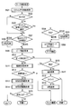
次に、サーチフェーズにおいて行われるサーチ制御処理について、図12に示すフローチャートを参照して説明する。
Next, search control processing performed in the search phase will be described with reference to the flowchart shown in FIG.
ステップS501において、システムコントローラ10は、スキャン駆動を開始し、スキャン駆動において、AFエリア群80、周辺エリア74、ターゲット監視エリア92等のそれぞれについて、フォーカスレンズの移動方向を判定するスキャン方向判断処理を行う。スキャン方向判断処理について、図13に示すフローチャートを参照して説明する。
In step S501, the system controller 10 starts scan driving, and performs scan direction determination processing for determining the moving direction of the focus lens for each of the AF area group 80, the peripheral area 74, the target monitoring area 92, and the like in the scan driving. Do. The scan direction determination process will be described with reference to the flowchart shown in FIG.
ステップS601において、システムコントローラ10は、後の判定で用いられる各種閾値の最適化する閾値の最適化処理を行う。ステップS602において、システムコントローラ10は、コントラスト値に係るAF評価値が増加したか減少したかを判定する。
In step S601, the system controller 10 performs threshold optimization processing for optimizing various threshold values used in later determination. In step S602, the system controller 10 determines whether the AF evaluation value related to the contrast value has increased or decreased.
AF評価値が増加したとき、処理はステップS603に進む。ステップS603において、システムコントローラ10は、AF評価値の増加をカウントするための変数cnt_incを増加させる。ステップS604において、システムコントローラ10は、AF評価値の変化について評価するAF評価値の比較処理を行う。
When the AF evaluation value increases, the process proceeds to step S603. In step S603, the system controller 10 increases the variable cnt_inc for counting the increase in the AF evaluation value. In step S604, the system controller 10 performs an AF evaluation value comparison process for evaluating a change in the AF evaluation value.
ステップS605において、システムコントローラ10は、カウンタcnt_incがステップS601で設定された所定の閾値以上であるか否かを判定する。閾値以上でないとき、スキャン方向判断処理は終了し、処理はサーチ制御処理に戻る。一方、閾値以上であるとき、処理はステップS606に進む。
In step S605, the system controller 10 determines whether or not the counter cnt_inc is greater than or equal to the predetermined threshold set in step S601. When it is not equal to or greater than the threshold value, the scan direction determination process ends and the process returns to the search control process. On the other hand, when it is equal to or greater than the threshold, the process proceeds to step S606.
ステップS606において、システムコントローラ10は、AF評価値についてステップS601で設定された所定の閾値以上の変化があるか否かを判定する。閾値以上の変化がないとき、スキャン方向判断処理は終了し、処理はサーチ制御処理に戻る。一方、閾値以上であるとき、処理はステップS607に進む。ステップS607において、システムコントローラ10は、スキャン方向は現在の方向である順方向とする旨を確定する。その後、スキャン方向判断処理は終了し、処理はサーチ制御処理に戻る。
In step S606, the system controller 10 determines whether or not there is a change in the AF evaluation value that is greater than or equal to the predetermined threshold set in step S601. When there is no change greater than the threshold value, the scan direction determination process ends, and the process returns to the search control process. On the other hand, if it is equal to or greater than the threshold, the process proceeds to step S607. In step S607, the system controller 10 determines that the scan direction is the forward direction, which is the current direction. Thereafter, the scan direction determination process ends, and the process returns to the search control process.
ステップS602において、AF評価値が減少していると判定されたとき、処理はステップS608に進む。ステップS608において、システムコントローラ10は、AF評価値の減少をカウントするための変数cnt_decを増加させる。ステップS609において、システムコントローラ10は、AF評価値の変化について評価するAF評価値の比較処理を行う。
When it is determined in step S602 that the AF evaluation value is decreasing, the process proceeds to step S608. In step S608, the system controller 10 increases the variable cnt_dec for counting the decrease in the AF evaluation value. In step S609, the system controller 10 performs AF evaluation value comparison processing for evaluating changes in the AF evaluation value.
ステップS610において、システムコントローラ10は、カウンタcnt_decがステップS601で設定された所定の閾値以上であるか否かを判定する。閾値以上でないとき、スキャン方向判断処理は終了し、処理はサーチ制御処理に戻る。一方、閾値以上であるとき、処理はステップS611に進む。
In step S610, the system controller 10 determines whether or not the counter cnt_dec is equal to or greater than the predetermined threshold set in step S601. When it is not equal to or greater than the threshold value, the scan direction determination process ends and the process returns to the search control process. On the other hand, when it is equal to or greater than the threshold, the process proceeds to step S611.
ステップS611において、システムコントローラ10は、AF評価値についてステップS601で設定された所定の閾値以上の変化があるか否かを判定する。閾値以上の変化がないとき、スキャン方向判断処理は終了し、処理はサーチ制御処理に戻る。一方、閾値以上であるとき、処理はステップS612に進む。ステップS612において、システムコントローラ10は、スキャン方向は現在の方向と反対方向である逆方向とする旨を確定する。その後、スキャン方向判断処理は終了し、処理はサーチ制御処理に戻る。
In step S611, the system controller 10 determines whether or not there is a change in the AF evaluation value that is greater than or equal to the predetermined threshold set in step S601. When there is no change greater than the threshold value, the scan direction determination process ends, and the process returns to the search control process. On the other hand, when it is equal to or greater than the threshold, the process proceeds to step S612. In step S612, the system controller 10 determines that the scan direction is the reverse direction opposite to the current direction. Thereafter, the scan direction determination process ends, and the process returns to the search control process.
このように、スキャン方向判断処理では、カウンタ及び変化の両方が所定の閾値以上であるとき、スキャン方向について順方向又は逆方向とする旨が確定される。
Thus, in the scan direction determination process, when both the counter and the change are equal to or greater than a predetermined threshold, it is determined that the scan direction is the forward direction or the reverse direction.
図12に戻ってサーチ制御処理について説明を続ける。ステップS501のスキャン方向判断処理の後、処理はステップS502に進む。ステップS502において、システムコントローラ10は、エリア配置モードがモードBであるか否かを判定する。モードBでないとき、処理はステップS507に進む。一方、エリア配置モードがモードBであるとき、処理はステップS503に進む。
Referring back to FIG. 12, the description of the search control process will be continued. After the scan direction determination process in step S501, the process proceeds to step S502. In step S502, the system controller 10 determines whether or not the area arrangement mode is mode B. When it is not mode B, the process proceeds to step S507. On the other hand, when the area arrangement mode is mode B, the process proceeds to step S503.
ステップS503において、システムコントローラ10は、ステップS501のスキャン方向判断処理の結果を参照して、ターゲット監視エリア92において、スキャン方向が確定しているか否かを判定する。ターゲット監視エリア92においてスキャン方向が確定していないとき、処理はステップS507に進む。一方、ターゲット監視エリア92においてスキャン方向が確定しているとき、処理はステップS504に進む。
In step S503, the system controller 10 refers to the result of the scan direction determination process in step S501 and determines whether or not the scan direction is fixed in the target monitoring area 92. When the scan direction is not fixed in the target monitoring area 92, the process proceeds to step S507. On the other hand, when the scan direction is fixed in the target monitoring area 92, the process proceeds to step S504.
ステップS504において、システムコントローラ10は、スキャン駆動すべき方向を判定する。スキャン方向が順方向で確定しているとき、処理はステップS506に進む。一方、スキャン方向が逆方向で確定しているとき、処理はステップS505に進む。ステップS505において、システムコントローラ10は、スキャン方向を逆転させる反転処理を行う。その後、処理はステップS506に進む。
In step S504, the system controller 10 determines the direction to be scanned. When the scan direction is fixed in the forward direction, the process proceeds to step S506. On the other hand, when the scan direction is determined in the reverse direction, the process proceeds to step S505. In step S505, the system controller 10 performs a reversal process that reverses the scan direction. Thereafter, the process proceeds to step S506.
ステップS506において、システムコントローラ10は、現在モードBとなっているエリア配置モードをモードAに変更する。すなわち、ターゲット監視エリア92にAFエリア群80が設定される。その後、サーチ制御処理を継続する。すなわち、処理はステップS501に戻る。
In step S506, the system controller 10 changes the area arrangement mode that is currently in mode B to mode A. That is, the AF area group 80 is set in the target monitoring area 92. Thereafter, the search control process is continued. That is, the process returns to step S501.
ステップS507において、システムコントローラ10は、AFエリア群80又は他の周辺エリア74でスキャン方向が確定しているか否かを判定する。逆方向でスキャン方向が確定しているとき、処理はステップS508に進む。ステップS508において、システムコントローラ10は、スキャン方向を反転させる反転処理を行う。その後、処理はステップS509に進む。ステップS507で逆方向でスキャン方向が確定していないとき、すなわち、順方向でスキャン方向が確定しているときやスキャン方向が確定していないとき、処理はステップS509に進む。
In step S507, the system controller 10 determines whether the scan direction is fixed in the AF area group 80 or other peripheral area 74. If the scan direction is determined in the reverse direction, the process proceeds to step S508. In step S508, the system controller 10 performs an inversion process for inverting the scan direction. Thereafter, the process proceeds to step S509. If the scan direction is not confirmed in the reverse direction in step S507, that is, if the scan direction is confirmed in the forward direction or the scan direction is not confirmed, the process proceeds to step S509.
ステップS509において、システムコントローラ10は、コントラスト値のピーク位置を調べるピーク検出処理を行う。ピーク検出処理では、AF評価値となるコントラスト値が最大値から減少したかを監視することによって、コントラスト値のピークを検出する。ステップS510において、システムコントローラ10は、ピーク位置が検出されたか否かを判定する。ピーク位置が検出されたとき、処理はステップS511に進む。
In step S509, the system controller 10 performs a peak detection process for checking the peak position of the contrast value. In the peak detection process, the peak of the contrast value is detected by monitoring whether the contrast value as the AF evaluation value has decreased from the maximum value. In step S510, the system controller 10 determines whether a peak position has been detected. When the peak position is detected, the process proceeds to step S511.
ステップS511において、システムコントローラ10は、ステップS509で検出されたコントラストのピーク値について、その信頼性を判定する信頼性判定処理を行う。
In step S511, the system controller 10 performs a reliability determination process for determining reliability of the peak value of the contrast detected in step S509.
ステップS512において、システムコントローラ10は、検出されたピーク値について信頼性あるか否かを判定する。信頼性がないと判定されたとき、サーチ制御処理を継続する。すなわち、処理はステップS501に戻る。一方、信頼性があると判定されたとき、処理はステップS513に進む。
In step S512, the system controller 10 determines whether or not the detected peak value is reliable. When it is determined that there is no reliability, the search control process is continued. That is, the process returns to step S501. On the other hand, when it is determined that there is reliability, the process proceeds to step S513.
ステップS513において、システムコントローラ10は、検出されたコントラストのピーク値に基づいて、合焦位置を演算によって求める合焦位置演算処理を行う。ステップS514において、システムコントローラ10は、ステップS513で算出された合焦位置にレンズを移動させる合焦位置駆動処理を行う。
In step S513, the system controller 10 performs an in-focus position calculation process for calculating the in-focus position based on the detected peak value of contrast. In step S514, the system controller 10 performs a focus position driving process for moving the lens to the focus position calculated in step S513.
ステップS515において、システムコントローラ10は、合焦位置にレンズを移動させた結果得られたコントラストのピーク値が非常に安定したものであるか否かを判定する。安定したピーク値であるとき、処理は待機制御処理に遷移する。一方、安定したピーク値でないとき、処理はwob制御処理に遷移し、フォーカスの微調整が行われる。
In step S515, the system controller 10 determines whether or not the peak value of the contrast obtained as a result of moving the lens to the in-focus position is very stable. When the peak value is stable, the process shifts to the standby control process. On the other hand, when the peak value is not stable, the process shifts to the web control process, and fine adjustment of the focus is performed.
ステップS510において、ピーク位置が検出されていないと判定されたとき、処理はステップS516に進む。ステップS516において、システムコントローラ10は、レンズ位置は端点にあるか否かを判定する。端点にないとき、サーチ制御処理を継続する。すなわち、処理はステップS501に戻る。一方、レンズ位置が端点にあると判定されたとき処理はステップS517に進む。
When it is determined in step S510 that the peak position has not been detected, the process proceeds to step S516. In step S516, the system controller 10 determines whether the lens position is at the end point. When it is not at the end point, the search control process is continued. That is, the process returns to step S501. On the other hand, when it is determined that the lens position is at the end point, the process proceeds to step S517.
ステップS517において、システムコントローラ10は、スキャン方向を反転させてピークの検出を続けるか否かに係る判断を行う端点処理を行う。ステップS518において、システムコントローラ10は、ステップS517の端点処理の結果、スキャン駆動をリトライするか否かを判定する。リトライしないとき、処理は待機制御処理に遷移する。一方、リトライするとき、処理はステップS519に進む。ステップS519において、システムコントローラ10は、反転処理を行う。その後、サーチ制御処理を継続する。すなわち、処理はステップS501に戻る。
In step S517, the system controller 10 performs end point processing for determining whether to invert the scan direction and continue to detect peaks. In step S518, the system controller 10 determines whether or not to retry scan driving as a result of the end point processing in step S517. When not retrying, the process transitions to a standby control process. On the other hand, when retrying, the process proceeds to step S519. In step S519, the system controller 10 performs inversion processing. Thereafter, the search control process is continued. That is, the process returns to step S501.
次に、待機制御処理について、図14に示すフローチャートを参照して説明する。
Next, the standby control process will be described with reference to the flowchart shown in FIG.
ステップS701において、システムコントローラ10は、各種状態に変化があったか否かを判定する。ここで変化として検出され得るものは、例えば、タッチパネル26がタッチされたことや、被写体の中に顔が検出されたり、検出されていた顔が消失したりすることや、特定の被写体に係る追尾について捕捉や喪失がされたことや、ジャイロセンサ回路28によって撮影装置1の姿勢の変化が検出されたことや、レンズ群21についてズーム動作が行われたことなどが挙げられる。状態に変化があると判定されたとき、処理はステップS702に進む。
In step S701, the system controller 10 determines whether various states have changed. What can be detected as the change here is, for example, that the touch panel 26 is touched, a face is detected in the subject, the detected face disappears, or tracking related to a specific subject. For example, a change in the attitude of the photographing apparatus 1 is detected by the gyro sensor circuit 28, and a zoom operation is performed on the lens group 21. When it is determined that the state has changed, the process proceeds to step S702.
ステップS702において、システムコントローラ10は、エリア配置モードを不明に設定する。その後、処理はwob制御処理に遷移する。
In step S702, the system controller 10 sets the area arrangement mode to unknown. Thereafter, the process transitions to a web control process.
ステップS701において、状態に変化がないと判定されたとき、処理はステップS703に進む。ステップS703において、システムコントローラ10は、コントラスト変化検出処理を行う。コントラスト変化検出処理は、図10を参照して説明した変化検出処理と同様の処理である。ただし、待機制御処理で行われるコントラスト変化検出処理は、AFエリア群80におけるコントラストの変化と、ターゲット監視エリア92におけるコントラストの変化とがそれぞれ検出され、さらにこれらは、異なる2種類のハイパスフィルタについて行われる。
If it is determined in step S701 that there is no change in state, the process proceeds to step S703. In step S703, the system controller 10 performs a contrast change detection process. The contrast change detection process is the same process as the change detection process described with reference to FIG. However, in the contrast change detection process performed in the standby control process, a contrast change in the AF area group 80 and a contrast change in the target monitoring area 92 are detected, and these are performed for two different types of high-pass filters. Is called.
コントラスト変化検出処理について、図15に示すフローチャートを参照して説明する。第1のハイパスフィルタ(HPF)及び第2のハイパスフィルタ(HPF)について、ステップS801乃至ステップS810の処理が行われる。
Contrast change detection processing will be described with reference to the flowchart shown in FIG. For the first high-pass filter (HPF) and the second high-pass filter (HPF), the processing from step S801 to step S810 is performed.
ステップS801において、システムコントローラ10は、AFエリア群80で増加方向の評価値の変化が第1の閾値よりも大きいか否かを判定する。第1の閾値よりも大きいとき、処理はステップS802に進む。ステップS802において、システムコントローラ10は、AFエリア群80の増加方向の変化検出カウント処理を行う。この処理は、図11を参照して説明した処理と同様の処理である。その後、処理はステップS806に進む。
In step S801, the system controller 10 determines whether or not the change in the evaluation value in the increasing direction in the AF area group 80 is greater than the first threshold value. If it is greater than the first threshold, the process proceeds to step S802. In step S <b> 802, the system controller 10 performs a change detection count process in the increasing direction of the AF area group 80. This process is the same as the process described with reference to FIG. Thereafter, the process proceeds to step S806.
ステップS801において、増加方向の評価値の変化が第1の閾値よりも大きくないと判定されたとき、処理はステップS803に進む。ステップS803において、システムコントローラ10は、AFエリア群80で減少方向の評価値の変化が第1の閾値よりも大きいか否かを判定する。第1の閾値よりも大きいとき、処理はステップS804に進む。ステップS804において、システムコントローラ10は、AFエリア群80の減少方向の変化検出カウント処理を行う。この処理は、図11を参照して説明した処理と同様の処理である。その後、処理はステップS806に進む。
When it is determined in step S801 that the change in the evaluation value in the increasing direction is not greater than the first threshold value, the process proceeds to step S803. In step S803, the system controller 10 determines whether or not the change in the evaluation value in the decreasing direction in the AF area group 80 is greater than the first threshold value. When it is larger than the first threshold value, the process proceeds to step S804. In step S804, the system controller 10 performs a change detection count process in the decreasing direction of the AF area group 80. This process is the same as the process described with reference to FIG. Thereafter, the process proceeds to step S806.
ステップS803において、減少方向の評価値の変化が第1の閾値よりも大きくないと判定されたとき、処理はステップS805に進む。ステップS805において、システムコントローラ10は、AFエリア群80の変化検出カウンタの初期化処理を行う。すなわち、システムコントローラ10は、AFエリア群80用の第1乃至第3の閾値用の増加方向カウンタ及び第1乃至第3の閾値用の減少方向カウンタの値を0にする。その後、処理はステップS806に進む。
If it is determined in step S803 that the change in the evaluation value in the decreasing direction is not greater than the first threshold value, the process proceeds to step S805. In step S <b> 805, the system controller 10 initializes the change detection counter of the AF area group 80. That is, the system controller 10 sets the values of the first to third threshold increase direction counters and the first to third threshold decrease direction counters for the AF area group 80 to zero. Thereafter, the process proceeds to step S806.
ステップS806において、システムコントローラ10は、ターゲット監視エリア92で増加方向の評価値の変化が第1の閾値よりも大きいか否かを判定する。第1の閾値よりも大きいとき、処理はステップS807に進む。ステップS807において、システムコントローラ10は、ターゲット監視エリア92の増加方向の変化検出カウント処理を行う。この処理は、図11を参照して説明した処理と同様の処理である。その後、処理はステップS811に進む。
In step S806, the system controller 10 determines whether or not the change in the evaluation value in the increasing direction is larger than the first threshold value in the target monitoring area 92. When it is larger than the first threshold value, the process proceeds to step S807. In step S <b> 807, the system controller 10 performs a change detection count process in the increasing direction of the target monitoring area 92. This process is the same as the process described with reference to FIG. Thereafter, the process proceeds to step S811.
ステップS806において、増加方向の評価値の変化が第1の閾値よりも大きくないと判定されたとき、処理はステップS808に進む。ステップS808において、システムコントローラ10は、ターゲット監視エリア92で減少方向の評価値の変化が第1の閾値よりも大きいか否かを判定する。第1の閾値よりも大きいとき、処理はステップS809に進む。ステップS809において、システムコントローラ10は、AFエリア群の減少方向の変化検出カウント処理を行う。この処理は、図11を参照して説明した処理と同様の処理である。その後、処理はステップS811に進む。
When it is determined in step S806 that the change in the evaluation value in the increasing direction is not greater than the first threshold value, the process proceeds to step S808. In step S808, the system controller 10 determines whether or not the change in the evaluation value in the decreasing direction is greater than the first threshold value in the target monitoring area 92. When it is larger than the first threshold value, the process proceeds to step S809. In step S809, the system controller 10 performs a change detection count process in the decreasing direction of the AF area group. This process is the same as the process described with reference to FIG. Thereafter, the process proceeds to step S811.
ステップS808において、減少方向の評価値の変化が第1の閾値よりも大きくないと判定されたとき、処理はステップS810に進む。ステップS810において、システムコントローラ10は、ターゲット監視エリア92の変化検出カウンタの初期化処理を行う。すなわち、システムコントローラ10は、ターゲット監視エリア92用の第1乃至第3の閾値用の増加方向カウンタ及び第1乃至第3の閾値用の減少方向カウンタの値を0にする。その後、処理はステップS811に進む。
When it is determined in step S808 that the change in the evaluation value in the decreasing direction is not greater than the first threshold value, the process proceeds to step S810. In step S <b> 810, the system controller 10 initializes a change detection counter in the target monitoring area 92. That is, the system controller 10 sets the values of the first to third threshold increase direction counters and the first to third threshold decrease direction counters for the target monitoring area 92 to zero. Thereafter, the process proceeds to step S811.
ステップS811において、システムコントローラ10は、変化検出完了条件を満たしているか否かを判定する。変化検出完了条件は、AFエリア群80又はターゲット監視エリア92におけるコントラスト変化の検出がなされたときに満たされる。変化検出完了条件が満たされていないとき、コントラスト変化検出処理は終了し、処理は待機制御処理に戻る。一方、変化検出完了条件が満たされているとき、処理はステップS812に進む。
In step S811, the system controller 10 determines whether or not a change detection completion condition is satisfied. The change detection completion condition is satisfied when a contrast change is detected in the AF area group 80 or the target monitoring area 92. When the change detection completion condition is not satisfied, the contrast change detection process ends, and the process returns to the standby control process. On the other hand, when the change detection completion condition is satisfied, the process proceeds to step S812.
ステップS812において、システムコントローラ10は、コントラスト変化を検出した旨を確定する。その後、コントラスト変化検出処理は終了し、処理は待機制御処理に戻る。
In step S812, the system controller 10 determines that a contrast change has been detected. Thereafter, the contrast change detection process ends, and the process returns to the standby control process.
図14に戻って待機制御処理の説明を続ける。コントラスト変化検出処理の後、処理はステップS704に進む。ステップS704において、システムコントローラ10は、コントラスト変化検出処理において、コントラスト変化が検出されたか否かを判定する。コントラスト変化が検出されたとき、処理はステップS702に進む。コントラスト変化が検出されていないとき、待機制御処理を継続する。すなわち、処理はステップS701に戻る。このように、上述した変化が生じたときにはウォブリングフェーズに移行し、変化が生じていないときには待機フェーズが維持される。
Referring back to FIG. 14, the explanation of the standby control process is continued. After the contrast change detection process, the process proceeds to step S704. In step S704, the system controller 10 determines whether or not a contrast change is detected in the contrast change detection process. When a contrast change is detected, the process proceeds to step S702. When the contrast change is not detected, the standby control process is continued. That is, the process returns to step S701. As described above, when the above-described change occurs, the process shifts to the wobbling phase, and when no change occurs, the standby phase is maintained.
以上で説明した処理におけるエリア配置モードの遷移の概略を示す状態遷移図を図16に示す。この図に示すように、待機フェーズから他のフェーズに遷移したとき、エリア配置モードは不明となる。エリア配置モードが不明なときにAF可否判定エリア72にコントラストがあるとき、エリア配置モードはモードAとなる。一方、AF可否判定エリア72のコントラストが低いとき、エリア配置モードはモードBとなる。また、エリア配置モードがモードBであるときに、ターゲット監視エリア92にコントラストが出現したとき、エリア配置モードはモードAとなる。
FIG. 16 shows a state transition diagram showing an outline of the transition of the area arrangement mode in the processing described above. As shown in this figure, when the transition from the standby phase to another phase is made, the area arrangement mode is unknown. When the area arrangement mode is unknown, the area arrangement mode is mode A when the AF availability determination area 72 has a contrast. On the other hand, when the contrast of the AF availability determination area 72 is low, the area arrangement mode is mode B. When the area arrangement mode is mode B and the contrast appears in the target monitoring area 92, the area arrangement mode is mode A.
また、エリア配置モードと、wobフェーズ、サーチフェーズ及び待機フェーズ間の遷移との関係の概略を示す状態遷移図を図17に示す。図17に示すように、各フェーズ及び各モード間で、所定の条件に応じて処理は遷移する。
FIG. 17 is a state transition diagram showing an outline of the relationship between the area arrangement mode and the transition between the web phase, the search phase, and the standby phase. As shown in FIG. 17, the process transitions between each phase and each mode according to a predetermined condition.
すなわち、ウォブリングフェーズのモードAにおいて、合焦位置が遠いことが明らかになったとき、処理はサーチフェーズのモードAに移行する。また、被写体のコントラストが非常に低い場合や合焦した場合やレンズ位置が端点に達してリトライしない場合には、処理は待機フェーズのモードAに移行する。また、AF可否判定エリア72のコントラストが低いとき、処理はウォブリングフェーズのモードBに移行する。
That is, in the wobbling phase mode A, when it becomes clear that the in-focus position is far, the processing shifts to the search phase mode A. Further, when the contrast of the subject is very low, when the subject is in focus, or when the lens position reaches the end point and the retry is not performed, the processing shifts to the standby phase mode A. Further, when the contrast of the AF availability determination area 72 is low, the process shifts to mode B of the wobbling phase.
サーチフェーズのモードAにおいて、コントラストのピーク値が検出できたとき、処理はウォブリングフェーズのモードAに移行する。また、合焦状態で安定したときや、レンズが端点に達してリトライしないとき、処理は待機フェーズのモードAに移行する。
When the contrast peak value is detected in the search phase mode A, the processing shifts to the wobbling phase mode A. Further, when the lens is stable in the focused state or when the lens reaches the end point and does not retry, the process shifts to the standby phase mode A.
待機フェーズのモードAにおいて、各種変化が検出されたとき、処理はウォブリングフェーズのモードAに移行する。
When various changes are detected in the standby phase mode A, the processing shifts to the wobbling phase mode A.
ウォブリングフェーズのモードBにおいて、合焦位置が遠いことが明らかになったとき、処理はサーチフェーズのモードBに移行する。また、被写体のコントラストが非常に低い場合や合焦した場合やレンズ位置が端点に達してリトライしない場合には、処理は待機フェーズのモードBに移行する。また、ターゲット監視エリア92にコントラストが出現したとき、処理はウォブリングフェーズのモードAに移行する。
In mode B of the wobbling phase, when it becomes clear that the in-focus position is far, the process shifts to mode B of the search phase. Further, when the contrast of the subject is very low, when the subject is in focus, or when the lens position reaches the end point and the retry is not performed, the processing shifts to the standby phase mode B. When contrast appears in the target monitoring area 92, the process shifts to mode A of the wobbling phase.
サーチフェーズのモードBにおいて、コントラストのピーク値が検出できたとき、処理はウォブリングフェーズのモードBに移行する。また、合焦状態で安定したときや、レンズが端点に達してリトライしないとき、処理は待機フェーズのモードBに移行する。また、ターゲット監視エリア92において合焦位置の方向が判定されたとき、処理はサーチフェーズのモードAに移行する。
In the search phase mode B, when the peak value of contrast is detected, the process shifts to the mode B of the wobbling phase. Further, when the lens is stabilized in the focused state, or when the lens reaches the end point and does not retry, the process shifts to the standby phase mode B. Further, when the direction of the in-focus position is determined in the target monitoring area 92, the processing shifts to the search phase mode A.
待機フェーズのモードBにおいて、各種変化が検出されたとき、処理はウォブリングフェーズのモードAに移行する。
When various changes are detected in mode B of the standby phase, the process shifts to mode A of the wobbling phase.
ここで、wob制御処理において用いられるAFエリア群80の一例について図18を参照して説明する。wob制御処理において用いられるAFエリア群80には、大エリア81と、中エリア82と、9個の小エリア83とが含まれる。これら11個のAFエリアを組み合わせて用いることで、様々な被写体に対して適当なAF動作を行うことができる。例えば図19に示すように、大エリア81や中エリア82内に、手前の被写体と奥の被写体とが含まれる時も、小エリア83を用いることで、正確に合焦することができる。このため、小エリア83による合焦方向や合焦位置の判断結果が、大エリア81や中エリア82の判断結果よりも優先されることが好ましい。なお、状態遷移する際には、方向判断に使用したエリアを、次の状態のAFエリア群80の中心とすることが好ましい。また、待機制御処理において図18のAFエリア群80を採用してもよい。
Here, an example of the AF area group 80 used in the web control process will be described with reference to FIG. The AF area group 80 used in the web control process includes a large area 81, a medium area 82, and nine small areas 83. By using these 11 AF areas in combination, an appropriate AF operation can be performed on various subjects. For example, as shown in FIG. 19, when the front area and the back area are included in the large area 81 and the middle area 82, the small area 83 can be used to focus accurately. For this reason, it is preferable that the determination result of the in-focus direction and the in-focus position by the small area 83 has priority over the determination result of the large area 81 and the middle area 82. In the state transition, it is preferable that the area used for direction determination is the center of the AF area group 80 in the next state. Further, the AF area group 80 of FIG. 18 may be employed in the standby control process.
また、サーチ制御処理において用いられるAFエリア群80の一例について図20を参照して説明する。サーチ制御処理において用いられるAFエリア群80には、複数のAFエリア85と、全面カバーエリア86とが含まれる。全面カバーエリア86は、補助的に用いられる。例えばAFエリア85でピーク検出ができずにレンズ位置が端点に到達してしまったときに、全面カバーエリアでピーク検出がなされていれば、その検出された位置にレンズを移動させる。また、待機制御処理において図20のAFエリア群80を採用してもよい。
An example of the AF area group 80 used in the search control process will be described with reference to FIG. The AF area group 80 used in the search control process includes a plurality of AF areas 85 and a full cover area 86. The entire cover area 86 is used as an auxiliary. For example, when peak detection cannot be performed in the AF area 85 and the lens position reaches the end point, if peak detection is performed in the entire surface cover area, the lens is moved to the detected position. Further, the AF area group 80 of FIG. 20 may be employed in the standby control process.
例えば図10を参照して説明したwob制御処理における変化検出処理の効果について図21を参照して説明する。図21の上から1番目の図に示すようにターゲット監視エリア92内のコントラストが低いとき、AFエリア群80は、周辺エリア74の内、コントラストがある部分に設定される。ここで、図21の上から2番目及び3番目の図に示すように、短期的にターゲット監視エリア92を通過する被写体があっても、継続時間閾値が適当に設定されることで、この一時的に通過する被写体のためにエリア配置モードがモードBからモードAに遷移しない。その結果、不必要なレンズ駆動が生じないという効果が得られる。サーチ制御処理におけるコントラスト変化検出処理についても同様の効果がある。
For example, the effect of the change detection process in the web control process described with reference to FIG. 10 will be described with reference to FIG. As shown in the first diagram from the top in FIG. 21, when the contrast in the target monitoring area 92 is low, the AF area group 80 is set to a portion having the contrast in the peripheral area 74. Here, as shown in the second and third diagrams from the top in FIG. 21, even if there is a subject that passes through the target monitoring area 92 in the short term, the duration threshold is appropriately set, and this temporary threshold is set. The area arrangement mode does not transition from mode B to mode A because of a subject that passes through automatically. As a result, there is an effect that unnecessary lens driving does not occur. The same effect can be obtained for the contrast change detection process in the search control process.
また、例えば図10を参照して説明したwob制御処理における変化検出処理の別の効果について図22及び図23を参照して説明する。例えば被写体が図22のようになっている場合を考える。すなわち、ターゲット監視エリア92に含まれる被写体は大きくぼけていてコントラストが低い状態となっている場合を考える。このとき、AFエリア群80は周辺エリア74に設定されている。この状態における時間に対するレンズ位置の変化を図23の上図に、時間に対するコントラストの変化を図23の下図に示す。図23の下図において、実線はターゲット監視エリア92におけるコントラスト変化を示し、破線はAFエリア群80におけるコントラスト変化を示す。図23に示すように、エリア配置モードがモードBであり、AFエリア群80において合焦しようとウォブリング駆動しているとき、ターゲット監視エリア92においても被写体が存在するためにコントラスト変化が生じる。このコントラスト変化が所定の閾値を超えたとき、エリア配置モードがモードAに切り替えられる。すなわち、ターゲット監視エリア92であったAF可否判定エリア72にAFエリア群80が設定され、このターゲット監視エリア92内の被写体に合焦することができる。
For example, another effect of the change detection process in the web control process described with reference to FIG. 10 will be described with reference to FIGS. For example, consider a case where the subject is as shown in FIG. That is, consider a case where the subject included in the target monitoring area 92 is largely blurred and has a low contrast. At this time, the AF area group 80 is set to the peripheral area 74. The change of the lens position with respect to time in this state is shown in the upper part of FIG. 23, and the change of contrast with respect to time is shown in the lower part of FIG. In the lower diagram of FIG. 23, the solid line indicates the contrast change in the target monitoring area 92, and the broken line indicates the contrast change in the AF area group 80. As shown in FIG. 23, when the area arrangement mode is mode B and wobbling driving is performed to focus in the AF area group 80, a contrast change occurs because the subject is also present in the target monitoring area 92. When this contrast change exceeds a predetermined threshold, the area arrangement mode is switched to mode A. That is, the AF area group 80 is set in the AF availability determination area 72 that was the target monitoring area 92, and the subject in the target monitoring area 92 can be focused.
サーチ制御処理においても同様である。図23と同様に、サーチ制御処理における時間に対するレンズ位置の変化を図24の上図に、時間に対するコントラストの変化を図24の下図に示す。図24の下図において、実線はターゲット監視エリア92におけるコントラスト変化を示し、破線はAFエリア群80におけるコントラスト変化を示す。この場合においても、エリア配置モードがモードBであり、AFエリア群80において合焦しようとスキャン駆動しているとき、ターゲット監視エリア92においても被写体が存在するためにコントラスト変化が生じる。このコントラスト変化が所定の閾値を超えたとき、エリア配置モードがモードAに切り替えられる。すなわち、ターゲット監視エリア92であったAF可否判定エリア72にAFエリア群80が設定され、このターゲット監視エリア92内の被写体に合焦することができる。
The same applies to search control processing. Similarly to FIG. 23, the change in the lens position with respect to time in the search control process is shown in the upper part of FIG. 24, and the change in contrast with respect to time is shown in the lower part of FIG. In the lower diagram of FIG. 24, the solid line indicates the contrast change in the target monitoring area 92, and the broken line indicates the contrast change in the AF area group 80. Also in this case, when the area arrangement mode is mode B and scanning is performed to focus on the AF area group 80, the contrast is changed because the subject is also present in the target monitoring area 92. When this contrast change exceeds a predetermined threshold, the area arrangement mode is switched to mode A. That is, the AF area group 80 is set in the AF availability determination area 72 that was the target monitoring area 92, and the subject in the target monitoring area 92 can be focused.
本実施形態によれば、ユーザが設定したAF可否判定エリア72のコントラストが高いとき、又はオールターゲットAFでの任意のAF可否判定エリア72のコントラストが高いとき、当該AF可否判定エリア72にAFエリア群80が設定されてAF動作がなされる。一方で、AF可否判定エリア72のコントラストが低いとき、周辺エリア74にAFエリア群80が設定されてAF動作がなされる。このため、コントラストがない領域で合焦しようとレンズを大きく動かすことが避けられる。本実施形態によれば、安定したオートフォーカスが実現され得る。
According to the present embodiment, when the contrast of the AF feasibility judgment area 72 set by the user is high, or when the contrast of an arbitrary AF feasibility judgment area 72 in the all target AF is high, the AF feasibility judgment area 72 includes the AF area. The group 80 is set and the AF operation is performed. On the other hand, when the contrast of the AF availability determination area 72 is low, the AF area group 80 is set in the peripheral area 74 and the AF operation is performed. For this reason, it is possible to avoid a large movement of the lens so as to focus in an area where there is no contrast. According to this embodiment, stable autofocus can be realized.
さらに、周辺エリア74にAFエリア群80が設定されているとき、AF可否判定エリア72にはターゲット監視エリア92が設けられ、コントラストの出現を監視する。このため、ターゲット監視エリア92においてコントラストが出現してこのエリアにおいて合焦できるときは、ターゲット監視エリア92に速やかにAFエリア群80が再設定され得る。このことにより、ユーザが設定したAF可否判定エリア72において適切な合焦が実現され得る。本実施形態によれば追従性が高いオートフォーカスが実現され得る。
Further, when the AF area group 80 is set in the peripheral area 74, a target monitoring area 92 is provided in the AF availability determination area 72 to monitor the appearance of contrast. For this reason, when contrast appears in the target monitoring area 92 and focusing is possible in this area, the AF area group 80 can be quickly reset in the target monitoring area 92. Accordingly, it is possible to achieve proper focusing in the AF availability determination area 72 set by the user. According to the present embodiment, autofocus with high followability can be realized.
Claims (6)
- 被写体像を受光して撮像し、画像データを生成する撮像部と、
前記被写体像を前記撮像部の撮像面に形成し、焦点調整用のフォーカスレンズを有する撮影光学系と、
前記画像データに基づいて、前記フォーカスレンズの移動を制御して焦点調整動作を行う制御部と
を有し、
前記制御部は、
前記画像データにより表される画像において、合焦状態の調整の対象となる領域である第1の焦点調整領域と、合焦状態の調整の対象となる領域であり前記第1の焦点調整領域よりも合焦の調整に係る優先度が低い第2の焦点調整領域とを設定し、
前記第1の焦点調整領域の画像データに基づく焦点調整が困難であるか否かを判定し、
前記第1の焦点調整領域の画像データに基づく焦点調整が困難であるとき、前記第2の焦点調整領域の画像データに基づく焦点調整を実行し、
前記第2の焦点調整領域の画像データに基づく焦点調整を実行している間に、前記第1の焦点調整領域の画像データに基づいて焦点調整が困難であるか否かを繰り返し判定し、
前記第1の焦点調整領域の画像データに基づく焦点調整が困難でないとき、前記第2の焦点調整領域の画像データに基づく焦点調整を停止し、前記第1の焦点調整領域の画像データに基づく焦点調整を実行する
撮影装置。 An imaging unit that receives and captures a subject image and generates image data;
An imaging optical system that forms the subject image on the imaging surface of the imaging unit and has a focus lens for focus adjustment;
A control unit for controlling the movement of the focus lens based on the image data and performing a focus adjustment operation,
The controller is
In the image represented by the image data, a first focus adjustment area that is an area to be adjusted in focus, and an area that is an object to be adjusted in focus, from the first focus adjustment area. And a second focus adjustment area having a low priority for focus adjustment,
Determining whether or not focus adjustment based on the image data of the first focus adjustment area is difficult;
When focus adjustment based on image data of the first focus adjustment area is difficult, focus adjustment based on image data of the second focus adjustment area is executed,
While performing focus adjustment based on the image data of the second focus adjustment area, it is repeatedly determined whether focus adjustment is difficult based on the image data of the first focus adjustment area,
When the focus adjustment based on the image data of the first focus adjustment area is not difficult, the focus adjustment based on the image data of the second focus adjustment area is stopped, and the focus based on the image data of the first focus adjustment area is stopped. An imaging device that performs the adjustment. - 前記制御部は、前記第2の焦点調整領域の画像データに基づく評価値を検出して焦点調整を実行している間に、前記第1の焦点調整領域の画像データに基づく評価値の所定値以上の変化を検出すると、前記第2の焦点調整領域の画像データに基づく焦点調整を停止し、前記第1の焦点調整領域の画像データに基づく焦点調整を実行する、請求項1に記載の撮影装置。 While the control unit detects an evaluation value based on the image data of the second focus adjustment area and performs focus adjustment, a predetermined value of the evaluation value based on the image data of the first focus adjustment area The imaging according to claim 1, wherein when the above change is detected, the focus adjustment based on the image data of the second focus adjustment area is stopped, and the focus adjustment based on the image data of the first focus adjustment area is executed. apparatus.
- 前記制御部は、
前記フォーカスレンズを所定の周期で前記撮影光学系の光軸方向に移動させながら前記撮像部に前記画像データを取得させるウォブリング動作を行うことができ、
前記ウォブリング動作により取得した前記第2の焦点調整領域の画像データに基づいて前記合焦状態に係る評価値を検出して焦点調整を実行している間に、前記ウォブリング動作により取得した前記第1の焦点調整領域の画像データに基づく前記評価値が所定値以上の変化を検出したとき、前記第2の焦点調整領域の画像データに基づく焦点調整を停止し、前記第1の焦点調整領域の画像データに基づく焦点調整を実行する、
請求項1に記載の撮影装置。 The controller is
A wobbling operation that allows the imaging unit to acquire the image data while moving the focus lens in the optical axis direction of the imaging optical system at a predetermined period can be performed.
The first value acquired by the wobbling operation while detecting the evaluation value related to the in-focus state based on the image data of the second focus adjustment region acquired by the wobbling operation and performing the focus adjustment. When the change in the evaluation value based on the image data in the focus adjustment area is detected to be greater than or equal to a predetermined value, the focus adjustment based on the image data in the second focus adjustment area is stopped, and the image in the first focus adjustment area Perform focus adjustments based on data,
The imaging device according to claim 1. - 前記制御部は、
前記フォーカスレンズを所定方向に移動させながら前記撮像部に前記画像データを取得させて合焦位置が存在する方向を判定するスキャン動作を行うことができ、
前記スキャン動作により取得した前記第2の焦点調整領域の画像データに基づき評価値を検出して焦点調整を実行している間に、前記スキャン動作により取得した前記第1の焦点調整領域の画像データに基づいて、合焦位置の存在する方向を判定すると、前記第2の焦点調整領域の画像データに基づく焦点調整を停止し、前記第1の焦点調整領域の画像データに基づく焦点調整を実行する、
請求項1に記載の撮影装置。 The controller is
While moving the focus lens in a predetermined direction, the image capturing unit can acquire the image data and perform a scanning operation for determining a direction in which a focus position exists,
The image data of the first focus adjustment area acquired by the scan operation while detecting the evaluation value based on the image data of the second focus adjustment area acquired by the scan operation and executing the focus adjustment. When the direction in which the in-focus position exists is determined based on the above, the focus adjustment based on the image data of the second focus adjustment area is stopped, and the focus adjustment based on the image data of the first focus adjustment area is executed. ,
The imaging device according to claim 1. - 前記制御部は、前記第1の焦点調整領域の画像データに基づく焦点調整が困難でないと判定した継続時間を計測し、前記継続時間が所定時間よりも長いとき、前記第2の焦点調整領域の画像データに基づく焦点調整を停止し、前記第1の焦点調整領域の画像データに基づく焦点調整を実行する、請求項1に記載の撮影装置。 The control unit measures a duration time when it is determined that the focus adjustment based on the image data of the first focus adjustment region is not difficult, and when the duration time is longer than a predetermined time, the control unit The imaging apparatus according to claim 1, wherein focus adjustment based on image data is stopped and focus adjustment based on image data in the first focus adjustment area is executed.
- 被写体像を受光して撮像し、画像データを生成する撮像部と、前記被写体像を前記撮像部の撮像面に形成し、焦点調整用のフォーカスレンズを有する撮影光学系とを有し、前記画像データに基づいて、前記フォーカスレンズの移動を制御して焦点調整動作を行う撮影装置を用いた撮影方法であって、
前記画像データにより表される画像において、合焦状態の調整の対象となる領域である第1の焦点調整領域と、合焦状態の調整の対象となる領域であり前記第1の焦点調整領域よりも合焦の調整に係る優先度が低い第2の焦点調整領域とを設定することと、
前記第1の焦点調整領域の画像データに基づく焦点調整が困難であるか否かを判定することと、
前記第1の焦点調整領域の画像データに基づく焦点調整が困難であるとき、前記第2の焦点調整領域の画像データに基づく焦点調整を実行することと、
前記第2の焦点調整領域の画像データに基づく焦点調整を実行している間に、前記第1の焦点調整領域の画像データに基づいて焦点調整が困難であるか否かを繰り返し判定することと、
前記第1の焦点調整領域の画像データに基づく焦点調整が困難でないとき、前記第2の焦点調整領域の画像データに基づく焦点調整を停止し、前記第1の焦点調整領域の画像データに基づく焦点調整を実行することと
を含む撮影方法。 An imaging unit that receives and captures a subject image and generates image data; and a photographing optical system that forms the subject image on an imaging surface of the imaging unit and includes a focus lens for focus adjustment. A photographing method using a photographing device that performs a focus adjustment operation by controlling movement of the focus lens based on data,
In the image represented by the image data, a first focus adjustment area that is an area to be adjusted in focus, and an area that is an object to be adjusted in focus, from the first focus adjustment area. Setting a second focus adjustment region having a low priority for adjusting the focus;
Determining whether focus adjustment based on image data of the first focus adjustment area is difficult;
When focus adjustment based on image data of the first focus adjustment area is difficult, executing focus adjustment based on image data of the second focus adjustment area;
Repetitively determining whether or not focus adjustment is difficult based on image data of the first focus adjustment area while performing focus adjustment based on image data of the second focus adjustment area; ,
When the focus adjustment based on the image data of the first focus adjustment area is not difficult, the focus adjustment based on the image data of the second focus adjustment area is stopped, and the focus based on the image data of the first focus adjustment area is stopped. A method of shooting including performing adjustment.
Priority Applications (3)
| Application Number | Priority Date | Filing Date | Title |
|---|---|---|---|
| CN201580069304.6A CN107111103B (en) | 2014-12-19 | 2015-03-25 | Camera and method for imaging |
| EP15869571.8A EP3236302A4 (en) | 2014-12-19 | 2015-03-25 | Imaging device and imaging method |
| US15/624,911 US10148866B2 (en) | 2014-12-19 | 2017-06-16 | Imaging device and imaging method |
Applications Claiming Priority (2)
| Application Number | Priority Date | Filing Date | Title |
|---|---|---|---|
| JP2014-257692 | 2014-12-19 | ||
| JP2014257692A JP2016118634A (en) | 2014-12-19 | 2014-12-19 | Imaging device and imaging method |
Related Child Applications (1)
| Application Number | Title | Priority Date | Filing Date |
|---|---|---|---|
| US15/624,911 Continuation US10148866B2 (en) | 2014-12-19 | 2017-06-16 | Imaging device and imaging method |
Publications (1)
| Publication Number | Publication Date |
|---|---|
| WO2016098362A1 true WO2016098362A1 (en) | 2016-06-23 |
Family
ID=56126267
Family Applications (1)
| Application Number | Title | Priority Date | Filing Date |
|---|---|---|---|
| PCT/JP2015/059192 WO2016098362A1 (en) | 2014-12-19 | 2015-03-25 | Imaging device and imaging method |
Country Status (5)
| Country | Link |
|---|---|
| US (1) | US10148866B2 (en) |
| EP (1) | EP3236302A4 (en) |
| JP (1) | JP2016118634A (en) |
| CN (1) | CN107111103B (en) |
| WO (1) | WO2016098362A1 (en) |
Families Citing this family (6)
| Publication number | Priority date | Publication date | Assignee | Title |
|---|---|---|---|---|
| JP2016197215A (en) * | 2015-04-06 | 2016-11-24 | オリンパス株式会社 | Focus adjustment device and method for controlling focus adjustment device |
| WO2017177465A1 (en) * | 2016-04-15 | 2017-10-19 | SZ DJI Technology Co., Ltd. | Contrast detection autofocus using adaptive step |
| US10044926B2 (en) * | 2016-11-04 | 2018-08-07 | Qualcomm Incorporated | Optimized phase detection autofocus (PDAF) processing |
| JP7316853B2 (en) * | 2019-06-28 | 2023-07-28 | キヤノン株式会社 | Imaging device and focus adjustment method |
| JP2021173827A (en) * | 2020-04-22 | 2021-11-01 | キヤノン株式会社 | Control unit, imaging apparatus, control method, and program |
| EP4300940A1 (en) * | 2021-03-25 | 2024-01-03 | Samsung Electronics Co., Ltd. | Electronic device including camera and control method therefor |
Citations (4)
| Publication number | Priority date | Publication date | Assignee | Title |
|---|---|---|---|---|
| JPH0638089A (en) * | 1992-07-20 | 1994-02-10 | Konica Corp | Automatic focusing device |
| JPH0646310A (en) * | 1992-07-21 | 1994-02-18 | Konica Corp | Automatic focusing device |
| JP2012013809A (en) * | 2010-06-29 | 2012-01-19 | Sharp Corp | Camera device, caf control method thereof, control program, readable storage medium, and electronic information apparatus |
| JP2012123324A (en) * | 2010-12-10 | 2012-06-28 | Fujifilm Corp | Imaging apparatus and main subject detection method |
Family Cites Families (9)
| Publication number | Priority date | Publication date | Assignee | Title |
|---|---|---|---|---|
| EP0341692B1 (en) * | 1988-05-11 | 1994-04-20 | Sanyo Electric Co., Ltd. | Image sensing apparatus having automatic focusing function for automatically matching focus in response to video signal |
| JP4182117B2 (en) * | 2006-05-10 | 2008-11-19 | キヤノン株式会社 | IMAGING DEVICE, ITS CONTROL METHOD, PROGRAM, AND STORAGE MEDIUM |
| JP5052127B2 (en) * | 2006-12-28 | 2012-10-17 | 三星電子株式会社 | Imaging apparatus and imaging method |
| JP5049712B2 (en) | 2007-09-14 | 2012-10-17 | キヤノン株式会社 | Imaging apparatus and focus control method |
| JP2009244431A (en) * | 2008-03-28 | 2009-10-22 | Canon Inc | Image pickup apparatus |
| JP5963606B2 (en) * | 2012-08-10 | 2016-08-03 | キヤノン株式会社 | Imaging apparatus and control method thereof |
| JP2014081420A (en) * | 2012-10-15 | 2014-05-08 | Olympus Imaging Corp | Tracking device and method thereof |
| JP6204660B2 (en) * | 2012-12-21 | 2017-09-27 | キヤノン株式会社 | Imaging apparatus and control method thereof |
| JP6415196B2 (en) * | 2014-09-08 | 2018-10-31 | キヤノン株式会社 | IMAGING DEVICE AND IMAGING DEVICE CONTROL METHOD |
-
2014
- 2014-12-19 JP JP2014257692A patent/JP2016118634A/en active Pending
-
2015
- 2015-03-25 CN CN201580069304.6A patent/CN107111103B/en active Active
- 2015-03-25 EP EP15869571.8A patent/EP3236302A4/en not_active Withdrawn
- 2015-03-25 WO PCT/JP2015/059192 patent/WO2016098362A1/en active Application Filing
-
2017
- 2017-06-16 US US15/624,911 patent/US10148866B2/en active Active
Patent Citations (4)
| Publication number | Priority date | Publication date | Assignee | Title |
|---|---|---|---|---|
| JPH0638089A (en) * | 1992-07-20 | 1994-02-10 | Konica Corp | Automatic focusing device |
| JPH0646310A (en) * | 1992-07-21 | 1994-02-18 | Konica Corp | Automatic focusing device |
| JP2012013809A (en) * | 2010-06-29 | 2012-01-19 | Sharp Corp | Camera device, caf control method thereof, control program, readable storage medium, and electronic information apparatus |
| JP2012123324A (en) * | 2010-12-10 | 2012-06-28 | Fujifilm Corp | Imaging apparatus and main subject detection method |
Non-Patent Citations (1)
| Title |
|---|
| See also references of EP3236302A4 * |
Also Published As
| Publication number | Publication date |
|---|---|
| JP2016118634A (en) | 2016-06-30 |
| US10148866B2 (en) | 2018-12-04 |
| CN107111103A (en) | 2017-08-29 |
| CN107111103B (en) | 2019-09-13 |
| EP3236302A4 (en) | 2018-08-22 |
| EP3236302A1 (en) | 2017-10-25 |
| US20170289439A1 (en) | 2017-10-05 |
Similar Documents
| Publication | Publication Date | Title |
|---|---|---|
| WO2016098362A1 (en) | Imaging device and imaging method | |
| JP6204644B2 (en) | Imaging apparatus and control method thereof | |
| CN110493528B (en) | Image pickup apparatus and control method thereof | |
| US20140198244A1 (en) | Focus aid system | |
| JP2016142925A (en) | Imaging apparatus, method of controlling the same, program, and storage medium | |
| JP2008032963A (en) | Optical device, imaging apparatus and its control method | |
| WO2018004001A1 (en) | Camera | |
| JP6234261B2 (en) | Focus adjustment apparatus and control method | |
| WO2018096790A1 (en) | Imaging device, method for controlling imaging device, and recording medium storing focus adjustment program | |
| JP2014215475A (en) | Imaging apparatus and method for controlling the same | |
| JP6087714B2 (en) | Imaging apparatus and control method thereof | |
| JP6501536B2 (en) | Imaging device, control method therefor, program, storage medium | |
| US10367991B2 (en) | Focus adjustment device and control method of focus adjustment device | |
| JP6289207B2 (en) | IMAGING DEVICE, IMAGING DEVICE CONTROL METHOD, IMAGING DEVICE CONTROL PROGRAM, AND STORAGE MEDIUM | |
| JP6087536B2 (en) | Imaging apparatus and control method thereof | |
| JP6425440B2 (en) | Imaging apparatus and imaging method | |
| JP6164978B2 (en) | FOCUS ADJUSTMENT DEVICE, ITS CONTROL METHOD, CONTROL PROGRAM, AND IMAGING DEVICE | |
| JP6788404B2 (en) | Focus adjustment device and focus adjustment method | |
| JP6747541B2 (en) | Imaging device | |
| JP6530609B2 (en) | Focusing device, imaging device, control method of focusing device, and program | |
| JP2016114721A (en) | Imaging apparatus and method of controlling the same | |
| JP6515452B2 (en) | Camera with contrast AF function | |
| JP2016142998A (en) | Focus adjustment unit, image capturing device, method of controlling focus adjustment unit, and program | |
| JP6581362B2 (en) | AUTOFOCUS DEVICE, ITS CONTROL METHOD, PROGRAM, AND RECORDING MEDIUM | |
| JP2005221798A (en) | Automatic focusing system |
Legal Events
| Date | Code | Title | Description |
|---|---|---|---|
| 121 | Ep: the epo has been informed by wipo that ep was designated in this application |
Ref document number: 15869571 Country of ref document: EP Kind code of ref document: A1 |
|
| NENP | Non-entry into the national phase |
Ref country code: DE |
|
| REEP | Request for entry into the european phase |
Ref document number: 2015869571 Country of ref document: EP |