WO2018096790A1 - Imaging device, method for controlling imaging device, and recording medium storing focus adjustment program - Google Patents
Imaging device, method for controlling imaging device, and recording medium storing focus adjustment program Download PDFInfo
- Publication number
- WO2018096790A1 WO2018096790A1 PCT/JP2017/035820 JP2017035820W WO2018096790A1 WO 2018096790 A1 WO2018096790 A1 WO 2018096790A1 JP 2017035820 W JP2017035820 W JP 2017035820W WO 2018096790 A1 WO2018096790 A1 WO 2018096790A1
- Authority
- WO
- WIPO (PCT)
- Prior art keywords
- focus
- focus adjustment
- subject
- adjustment operation
- value
- Prior art date
Links
Images


Classifications
-
- H—ELECTRICITY
- H04—ELECTRIC COMMUNICATION TECHNIQUE
- H04N—PICTORIAL COMMUNICATION, e.g. TELEVISION
- H04N23/00—Cameras or camera modules comprising electronic image sensors; Control thereof
- H04N23/60—Control of cameras or camera modules
- H04N23/67—Focus control based on electronic image sensor signals
- H04N23/673—Focus control based on electronic image sensor signals based on contrast or high frequency components of image signals, e.g. hill climbing method
-
- G—PHYSICS
- G02—OPTICS
- G02B—OPTICAL ELEMENTS, SYSTEMS OR APPARATUS
- G02B7/00—Mountings, adjusting means, or light-tight connections, for optical elements
- G02B7/28—Systems for automatic generation of focusing signals
-
- G—PHYSICS
- G02—OPTICS
- G02B—OPTICAL ELEMENTS, SYSTEMS OR APPARATUS
- G02B7/00—Mountings, adjusting means, or light-tight connections, for optical elements
- G02B7/28—Systems for automatic generation of focusing signals
- G02B7/36—Systems for automatic generation of focusing signals using image sharpness techniques, e.g. image processing techniques for generating autofocus signals
-
- G—PHYSICS
- G03—PHOTOGRAPHY; CINEMATOGRAPHY; ANALOGOUS TECHNIQUES USING WAVES OTHER THAN OPTICAL WAVES; ELECTROGRAPHY; HOLOGRAPHY
- G03B—APPARATUS OR ARRANGEMENTS FOR TAKING PHOTOGRAPHS OR FOR PROJECTING OR VIEWING THEM; APPARATUS OR ARRANGEMENTS EMPLOYING ANALOGOUS TECHNIQUES USING WAVES OTHER THAN OPTICAL WAVES; ACCESSORIES THEREFOR
- G03B13/00—Viewfinders; Focusing aids for cameras; Means for focusing for cameras; Autofocus systems for cameras
- G03B13/32—Means for focusing
- G03B13/34—Power focusing
- G03B13/36—Autofocus systems
-
- H—ELECTRICITY
- H04—ELECTRIC COMMUNICATION TECHNIQUE
- H04N—PICTORIAL COMMUNICATION, e.g. TELEVISION
- H04N23/00—Cameras or camera modules comprising electronic image sensors; Control thereof
- H04N23/60—Control of cameras or camera modules
-
- H—ELECTRICITY
- H04—ELECTRIC COMMUNICATION TECHNIQUE
- H04N—PICTORIAL COMMUNICATION, e.g. TELEVISION
- H04N23/00—Cameras or camera modules comprising electronic image sensors; Control thereof
- H04N23/60—Control of cameras or camera modules
- H04N23/67—Focus control based on electronic image sensor signals
- H04N23/675—Focus control based on electronic image sensor signals comprising setting of focusing regions
-
- H—ELECTRICITY
- H04—ELECTRIC COMMUNICATION TECHNIQUE
- H04N—PICTORIAL COMMUNICATION, e.g. TELEVISION
- H04N23/00—Cameras or camera modules comprising electronic image sensors; Control thereof
- H04N23/60—Control of cameras or camera modules
- H04N23/68—Control of cameras or camera modules for stable pick-up of the scene, e.g. compensating for camera body vibrations
- H04N23/681—Motion detection
- H04N23/6811—Motion detection based on the image signal
-
- H—ELECTRICITY
- H04—ELECTRIC COMMUNICATION TECHNIQUE
- H04N—PICTORIAL COMMUNICATION, e.g. TELEVISION
- H04N23/00—Cameras or camera modules comprising electronic image sensors; Control thereof
- H04N23/60—Control of cameras or camera modules
- H04N23/68—Control of cameras or camera modules for stable pick-up of the scene, e.g. compensating for camera body vibrations
- H04N23/682—Vibration or motion blur correction
- H04N23/683—Vibration or motion blur correction performed by a processor, e.g. controlling the readout of an image memory
Definitions
- the present invention relates to an imaging apparatus, an imaging apparatus control method, and a recording medium on which a focus adjustment program is recorded.
- An object of the present invention is to provide an imaging apparatus capable of performing an optimum autofocus operation according to the movement of a subject, a control method for the imaging apparatus, and a recording medium on which a focus adjustment program is recorded.
- the recording medium receives a light from a subject via a photographing lens including a focus lens, and obtains the imaging signal from an imaging element that generates an imaging signal of a predetermined imaging region.
- a non-transitory computer-readable recording medium storing a focus adjustment program executed by the focus detection program, wherein the focus adjustment program includes a focus detection area inside the imaging area and at least a part of the focus detection area Setting a motion detection region, determining instability of the subject with respect to motion based on the imaging signal corresponding to the inside of the motion detection region, and corresponding to the inside of the focus detection region
- the focus lens is determined based on the imaging signal, and the focus lens is moved for focus adjustment based on the focus level.
- the focus adjustment operation is stopped, and after the subject is determined to be stable, the focus adjustment operation is started.
- the computer is caused to change the operation parameter of the focus adjustment operation. .
- FIG. 1 shows an outline of a configuration example of the imaging apparatus 1 according to the present embodiment.
- the imaging device 1 includes a system controller 10 that controls the operation of each unit of the imaging device 1.
- the imaging apparatus 1 includes a lens group 21, a diaphragm 22, a shutter 23, an imaging element 24, a focus adjustment mechanism 31, a diaphragm driving mechanism 32, a shutter driving mechanism 33, and an imaging element IF circuit 34.
- the lens group 21 as a photographing lens includes a plurality of lenses.
- the lens group 21 includes a focus lens for adjusting the focus.
- the focus of the subject image formed on the image sensor 24 is adjusted by moving the focus lens in the optical axis direction.
- the diaphragm 22 adjusts the amount of light incident on the image sensor 24 via the lens group 21.
- the optical system including the lens group 21 and the diaphragm 22 may be configured as an interchangeable lens that can be attached to and detached from the main body of the imaging apparatus 1.
- the shutter 23 is provided in front of the image sensor 24 and controls the incidence of light on the image sensor 24 via the lens group 21.
- the image sensor 24 includes, for example, a CCD image sensor or a CMOS image sensor.
- the image sensor 24 receives a light beam passing through the lens group 21, that is, a subject image formed by the lens group 21, and creates an imaging signal by photoelectric conversion.
- the focus adjustment mechanism 31 moves the focus lens included in the lens group 21 in the optical axis direction to adjust the focus under the control of the system controller 10.
- the aperture drive mechanism 32 drives the aperture 22 under the control of the system controller 10.
- the shutter drive mechanism 33 drives the shutter 23 under the control of the system controller 10.
- the image sensor IF circuit 34 reads an image signal from the image sensor and outputs image data converted into a digital signal to the system controller 10.
- the imaging apparatus 1 further includes a display element 25, a touch panel 26, a display element driving circuit 35, a touch panel driving circuit 36, a camera operation switch 27, and a gyro sensor circuit 28.
- the display element driving circuit 35 controls the display operation by the display element 25 under the control of the system controller 10.
- the touch panel drive circuit 36 controls the acquisition of touch input by the touch panel 26 under the control of the system controller 10.
- the camera operation switch 27 includes, for example, a release switch, a recording button, a cross key for performing various inputs, and the like.
- the camera operation switch 27 acquires an input by the user and transmits the input to the system controller 10.
- the gyro sensor circuit 28 detects the movement of the imaging device 1.
- the gyro sensor circuit 28 transmits information related to the movement of the imaging device 1 to the system controller 10.
- the gyro sensor circuit 28 may include not only an angular velocity sensor that detects an angular velocity but also an acceleration sensor.
- the gyro sensor circuit 28 functions as, for example, a camera shake detection unit.
- the imaging apparatus 1 further includes a Flash Rom 41, an SDRAM 42, and a recording medium 43.
- the Flash Rom 41 records, for example, a program code 41a and a control parameter 41b that are used by the system controller 10 for controlling the operation of the imaging device 1.
- the SDRAM 42 is provided with a Work Area 42a that is a storage area used for calculation by the system controller 10.
- the recording medium 43 records a still image file and a moving image file 43a photographed by the imaging device 1.
- the recording medium 43 is detachable from the imaging apparatus 1.
- the CPU 11 performs various calculations using the program code 41a and the control parameter 41b recorded in the Flash Rom 41.
- the AF control circuit 12 performs various calculations related to AF and controls operations of the focus adjustment mechanism 31 and the like.
- the AE control circuit 13 performs various calculations related to exposure control, and controls operations of the aperture driving mechanism 32, the shutter driving mechanism 33, and the like.
- the image processing circuit 14 performs image processing on the image data generated by the image sensor 24 and acquired via the image sensor IF circuit 34.
- the face recognition circuit 15 performs face recognition processing for recognizing a face included in the subject photographed by the image sensor 24.
- the moving image recording circuit 16 records the moving image data generated by the image sensor 24, acquired via the image sensor IF circuit 34, and image-processed by the image processing circuit 14, on the recording medium 43.
- the minute driving phase the focus lens is minutely moved alternately in the infinity direction and the closest direction, for example, every frame.
- the focus is finely adjusted or the direction of the in-focus position is determined.
- Such an operation of the focus lens will be referred to as a minute driving operation.
- the minute driving operation is also called a wobbling operation.
- FIG. 3 is a diagram for explaining a method for determining the direction of the in-focus position by the minute driving operation.
- the solid line indicates the change in the lens position with time
- the broken line indicates the contrast value of the image obtained with respect to the lens position.
- the direction of the in-focus position can be determined. Of the infinity direction and the closest direction, the direction in which the contrast value increases is the direction of the in-focus position.
- the imaging apparatus 1 of the present embodiment operates so as to always focus on a subject as moving image AF during moving image shooting.
- the imaging device 1 continues to operate while changing the control phase.
- the control phase includes a micro drive phase (micro drive), a search phase (search), and a standby phase (standby). At the start of moving image recording, control starts from the minute drive phase.
- the operation phase shifts to the search phase.
- the search phase By shifting to the search phase, the lens position quickly moves to the in-focus position.
- the operation phase transitions to the standby phase, and the lens driving is stopped.
- a motion vector refers to a moving direction and a moving amount of a feature point obtained by searching a subsequent image for a feature point having a strong correlation with a feature point in a previous image in a continuous image obtained by continuous shooting. It is a vector that represents.
- a motion vector detection area 71 as a motion detection area is used.
- a person 78 indicated by a broken line indicates the position of the subject of interest of the previous image among consecutive images before and after
- a person 79 indicated by a solid line indicates the subject of interest of the subsequent image among consecutive images. Indicates the position.
- the subject instability determination process performed in step S102 will be described with reference to FIG.
- Three states of “stable”, “unstable”, and “waiting for stability confirmation” are defined as states relating to instability of the subject.
- the stable state is a state where the subject is stable.
- a stable state is assumed at the start of judgment.
- the unstable state is a state where the subject is unstable.
- the stabilization waiting state is a state in which an unstable subject is stable and shortly after. That is, when the motion vector is stabilized in the unstable state, the state transitions to the stability determination waiting state.
- the state transitions to an unstable state.
- step S201 the motion vector calculation circuit 17 performs a motion vector absolute value calculation process. That is, the motion vector calculation circuit 17 takes absolute values for the value of the motion vector in the X direction and the value of the motion vector in the Y direction, and adds these absolute values. The value thus obtained is used as an instability evaluation value for evaluating the instability of the subject.
- step S103 The AF control process performed in step S103 will be described with reference to the flowchart shown in FIG.
- step S402 the AF control circuit 12 determines whether or not it is immediately after the unstable state parameter of the subject becomes stable.
- the determination in step S402 is performed for the first time after the unstable state parameter is stably changed, or when an in-focus state confirmation process to be described later is being continued, it is determined that the state is immediately after becoming stable.
- the In step S ⁇ b> 402 it is determined that the unstable state parameter is changed only stably by determining that the unstable state parameter is waiting for stability determination last time and is stable this time.
- the in-focus state confirmation processing flag if it is 1, it is determined that it is continuing. If it is immediately after becoming stable, the process proceeds to step S403.
- step S501 the AF control circuit 12 determines whether or not there is a possibility that the main subject is small compared to the size of the AF area 81 currently used.
- the main subject is smaller than the AF area 81, the main subject and the background are mixed in the AF area 81.
- the position of the focus lens is fixed so as to focus on the background, and the main subject may not be focused.
- the AF area 81 is set small only when the main subject is small. If it is determined that the main subject is smaller than the size of the AF area 81, the process proceeds to step S502.
- step S502 the AF control circuit 12 determines that the subject is a small subject. Thereafter, the process proceeds to step S509.
- step S404 the AF control circuit 12 performs direction determination processing.
- the AF control circuit 12 determines the direction of the in-focus position based on the current moving direction of the focus lens and the change in contrast value. After the direction determination process in step S404, the process proceeds to step S409.
- step S406 the AF control circuit 12 performs focus determination processing.
- the AF control circuit 12 checks whether or not the current focus lens position is the focus position.
- the AF control circuit 12 sets the phase of the AF operation as a standby phase. For example, when the focus lens is moved in the direction in which the contrast value increases, when the reversal of the movement direction of the focus lens is repeatedly performed within a certain range, the focus position is near the center of the focus lens movement. Can be identified.
- the phase of the AF operation transitions to the standby phase, the minute drive control process described here is exited.
- the transition to the standby phase is not made, the process proceeds to step S407.
- the focus determination process in step S406 is performed only when the subject state is stable and not immediately after it is stabilized. Therefore, it is determined that the subject is in focus and the AF operation phase is changed to the standby phase only when the subject state is stable and a predetermined time has elapsed. Further, after the subject state is stabilized, a timer is provided to measure the elapsed time, and the transition to the standby phase is prohibited for a predetermined time, thereby further improving the AF stability.
- step S407 If the result of the focus state confirmation process is that the subject is a small subject and the focus position is near the focus position, the transition to the search phase is suppressed. After the process of step S407, the process proceeds to step S409.
- the value of the motion vector is small and the subject is stable. At this time, AF operation by minute driving is performed. Assume that the value of the motion vector exceeds the instability threshold at time t1. It is determined that the state of the subject is unstable after time t1. Thereafter, when the value of the motion vector is larger than the instability threshold, it is determined that the state of the subject is unstable. On the other hand, when the value of the motion vector becomes equal to or less than the instability threshold, the state of the subject waits for stability determination. If the value of the motion vector becomes larger than the instability threshold before the predetermined period has elapsed in the state of waiting for stability confirmation, the state of the subject is determined to be unstable again.
- the state of the subject becomes stable.
- the state of the subject is stable at time t2.
- the AF operation is stopped from time t1 to time t2 when the subject is unstable or waiting for stability determination.
- the AF operation resumes, and the AF operation continues until the motion vector value exceeds the instability threshold.
- the AF operation phase is not changed to the standby phase or the search phase from time t2 to time t3 until the predetermined period elapses after the state of the subject changes stably.
- the AF operation phase can be changed to a standby phase or a search phase depending on the situation.
- the moving image shooting has been particularly described. However, not only the moving image shooting but also the AF operation during live view display for still image shooting functions in a similar manner.
- the contrast AF evaluation method for evaluating the degree of focus based on the contrast of the image has been described.
- the present invention is not limited to this.
- the above-described technique for changing whether or not to perform the AF operation by evaluating the stability of the subject can be similarly applied to the phase difference AF evaluation method for evaluating the degree of focus based on the phase difference of the subject image. .
- the AF operation according to the above-described embodiment can be applied not only to a consumer digital camera but also to an information portable terminal such as a smartphone or a tablet terminal.
- the information portable terminal includes a wearable terminal.
- the AF operation according to the present embodiment can also be applied to surveillance cameras, cameras for microscopes, industrial equipment such as inspection, various medical observation apparatuses and endoscopes.
- surveillance cameras cameras for microscopes, industrial equipment such as inspection, various medical observation apparatuses and endoscopes.
- an endoscope for example, when a subject becomes unstable due to pulsation of an organ, or when a treatment tool enters an imaging range instead of an organ, etc. AF malfunction is suppressed.
- the AF operation according to the present embodiment is used for a surveillance camera, it is possible to prevent the AF from malfunctioning due to the movement of a person who goes and goes.
Abstract
An imaging device (1) comprises: an imaging element (24); a setting unit (102) that establishes a focal point detection area in an imaging area, and establishes a movement detection area at least a part of which is included in the focal point detection area; a determination unit (104) that determines the instability of a subject in terms of movement; and a focus adjustment unit (106) that moves a focus lens to adjust the focus on the basis of the degree of focus determined. The focus adjustment unit (106) stops a focus adjustment operation when the determination unit (104) determines that the subject is unstable, starts the focus adjustment operation after the subject is determined to be stable, and changes an operation parameter for the focus adjustment when restarting the focus adjustment operation due to the determination that the subject is stable after stopping the focus adjustment operation due to the determination that the subject is unstable.
Description
本発明は、撮像装置、撮像装置の制御方法、焦点調節プログラムを記録した記録媒体に関する。
The present invention relates to an imaging apparatus, an imaging apparatus control method, and a recording medium on which a focus adjustment program is recorded.
撮像装置において、被写体に合焦するように撮像光学系に含まれるフォーカスレンズを移動させるオートフォーカス(AF)機能が知られている。このようなオートフォーカス機能において、被写体が動いているときなど、AFの誤作動が生じやすい。このため、例えば日本国特開2003-230043号公報には、被写体の動きを検出したらAF動作を停止させることについて開示されている。一方で、AF動作を停止させれば、当然被写体に合焦する状態を維持できなくなる。
In an imaging apparatus, an autofocus (AF) function for moving a focus lens included in an imaging optical system so as to focus on a subject is known. In such an autofocus function, an AF malfunction tends to occur when the subject is moving. For this reason, for example, Japanese Patent Application Laid-Open No. 2003-230043 discloses that the AF operation is stopped when the movement of the subject is detected. On the other hand, if the AF operation is stopped, it is naturally impossible to maintain a state where the subject is in focus.
本発明は、被写体の動きに応じて最適なオートフォーカス動作を行うことができる撮像装置、撮像装置の制御方法、焦点調節プログラムを記録した記録媒体を提供することを目的とする。
An object of the present invention is to provide an imaging apparatus capable of performing an optimum autofocus operation according to the movement of a subject, a control method for the imaging apparatus, and a recording medium on which a focus adjustment program is recorded.
本発明の一態様によれば、撮像装置は、フォーカスレンズを含む撮影レンズを介して被写体からの光を受光して所定の撮像領域の撮像信号を生成する撮像素子と、前記撮像領域の内部に焦点検出領域と、少なくとも一部が前記焦点検出領域に含まれる動き検出領域とを設定する設定部と、前記動き検出領域の内部に対応する前記撮像信号に基づいて、動きについての前記被写体の不安定さを判定する判定部と、前記焦点検出領域の内部に対応する前記撮像信号に基づいて合焦度を判定し、前記合焦度に基づいて焦点調節のために前記フォーカスレンズを移動させる焦点調節動作を行う焦点調節部とを備え、前記焦点調節部は、前記判定部により前記被写体が不安定と判定されたときには前記焦点調節動作を停止し、前記判定部により前記被写体が安定と判定された後に前記焦点調節動作を開始し、前記判定部により一度前記被写体が不安定と判定されて前記焦点調節動作を停止しその後前記被写体が安定と判定されて前記焦点調節動作を再開する際には、前記焦点調節動作の動作パラメータを異ならせる。
According to one aspect of the present invention, an imaging device includes an imaging element that receives light from a subject via a photographic lens including a focus lens and generates an imaging signal of a predetermined imaging area, and an imaging device inside the imaging area. Based on the imaging signal corresponding to the interior of the motion detection area, a setting unit that sets a focus detection area, a motion detection area at least part of which is included in the focus detection area, A determination unit for determining stability, and a focus for determining a focus degree based on the imaging signal corresponding to the inside of the focus detection area, and moving the focus lens for focus adjustment based on the focus degree A focus adjustment unit that performs an adjustment operation, and the focus adjustment unit stops the focus adjustment operation when the determination unit determines that the subject is unstable, and the determination unit determines After the body is determined to be stable, the focus adjustment operation is started. The determination unit once determines that the subject is unstable and stops the focus adjustment operation, and then the subject is determined to be stable and the focus adjustment operation. When resuming, the operation parameter of the focus adjustment operation is changed.
本発明の一態様によれば、撮像装置の制御方法は、フォーカスレンズを含む撮影レンズを介して被写体からの光を受光して所定の撮像領域の撮像信号を生成することと、前記撮像領域の内部に焦点検出領域と、少なくとも一部が前記焦点検出領域に含まれる動き検出領域とを設定することと、前記動き検出領域の内部に対応する前記撮像信号に基づいて、動きについての前記被写体の不安定さを判定することと、前記焦点検出領域の内部に対応する前記撮像信号に基づいて合焦度を判定することと、前記合焦度に基づいて焦点調節のために前記フォーカスレンズを移動させる焦点調節動作を行うことであって、前記被写体が不安定と判定されたときには前記焦点調節動作を停止し、前記被写体が安定と判定された後に前記焦点調節動作を開始し、一度前記被写体が不安定と判定されて前記焦点調節動作を停止しその後前記被写体が安定と判定されて前記焦点調節動作を再開する際には、前記焦点調節動作の動作パラメータを異ならせることとを含む。
According to an aspect of the present invention, a method for controlling an imaging apparatus includes receiving a light from a subject via a photographing lens including a focus lens and generating an imaging signal of a predetermined imaging region; Setting a focus detection area inside and a motion detection area at least part of which is included in the focus detection area, and based on the imaging signal corresponding to the inside of the motion detection area, Determining instability, determining a focus level based on the imaging signal corresponding to the inside of the focus detection area, and moving the focus lens for focus adjustment based on the focus level When the subject is determined to be unstable, the focus adjustment operation is stopped, and the focus adjustment operation is started after the subject is determined to be stable. When the subject is determined to be unstable and the focus adjustment operation is stopped, and then the subject is determined to be stable and the focus adjustment operation is restarted, the operation parameters of the focus adjustment operation are varied. Including.
本発明の一態様によれば、記録媒体は、フォーカスレンズを含む撮影レンズを介して被写体からの光を受光して所定の撮像領域の撮像信号を生成する撮像素子から前記撮像信号を取得するコンピュータによって実行される焦点調節プログラムを記憶したコンピュータ読み取り可能な非一時的記録媒体であり、前記焦点調節プログラムは、前記撮像領域の内部に焦点検出領域と、少なくとも一部が前記焦点検出領域に含まれる動き検出領域とを設定することと、前記動き検出領域の内部に対応する前記撮像信号に基づいて、動きについての前記被写体の不安定さを判定することと、前記焦点検出領域の内部に対応する前記撮像信号に基づいて合焦度を判定することと、前記合焦度に基づいて焦点調節のために前記フォーカスレンズを移動させる焦点調節動作を行うことであって、前記被写体が不安定と判定されたときには前記焦点調節動作を停止し、前記被写体が安定と判定された後に前記焦点調節動作を開始し、一度前記被写体が不安定と判定されて前記焦点調節動作を停止しその後前記被写体が安定と判定されて前記焦点調節動作を再開する際には、前記焦点調節動作の動作パラメータを異ならせることとを前記コンピュータに実行させる。
According to one aspect of the present invention, the recording medium receives a light from a subject via a photographing lens including a focus lens, and obtains the imaging signal from an imaging element that generates an imaging signal of a predetermined imaging region. A non-transitory computer-readable recording medium storing a focus adjustment program executed by the focus detection program, wherein the focus adjustment program includes a focus detection area inside the imaging area and at least a part of the focus detection area Setting a motion detection region, determining instability of the subject with respect to motion based on the imaging signal corresponding to the inside of the motion detection region, and corresponding to the inside of the focus detection region The focus lens is determined based on the imaging signal, and the focus lens is moved for focus adjustment based on the focus level. When the subject is determined to be unstable, the focus adjustment operation is stopped, and after the subject is determined to be stable, the focus adjustment operation is started. When the focus adjustment operation is determined to be stable and then the subject is determined to be stable and the focus adjustment operation is restarted, the computer is caused to change the operation parameter of the focus adjustment operation. .
本発明によれば、被写体の動きに応じて最適なオートフォーカス動作を行うことができる撮像装置、撮像装置の制御方法、焦点調節プログラムを記録した記録媒体を提供できる。
According to the present invention, it is possible to provide an imaging apparatus capable of performing an optimum autofocus operation according to the movement of the subject, a control method for the imaging apparatus, and a recording medium on which a focus adjustment program is recorded.
本発明の一実施形態について図面を参照して説明する。本実施形態に係る撮像装置は、動画撮影時に被写体に関するコントラスト値に基づいて合焦度を判定し、フォーカスレンズの合焦位置を調整するコントラスト評価方式のオートフォーカス(AF)機能を有する。本撮像装置は、AF動作中に被写体に動きがある場合等、AF動作が不安定な状況になりやすい場合には、AF動作を停止してAFの品質を維持する。一方で、本撮像装置は、AFの追従性を維持するために、被写体に動きがある場合等でも必要なAF動作は行う。
An embodiment of the present invention will be described with reference to the drawings. The imaging apparatus according to the present embodiment has a contrast evaluation type autofocus (AF) function that determines a focus degree based on a contrast value related to a subject during moving image shooting and adjusts a focus position of a focus lens. The imaging apparatus stops the AF operation and maintains the AF quality when the AF operation tends to be unstable, such as when the subject moves during the AF operation. On the other hand, in order to maintain AF follow-up performance, the imaging apparatus performs necessary AF operations even when the subject moves.
[撮像装置の構成]
本実施形態に係る撮像装置1の構成例の概略を図1に示す。図1に示すように、撮像装置1は、撮像装置1の各部の動作を制御するシステムコントローラ10を備える。また、撮像装置1は、レンズ群21と、絞り22と、シャッタ23と、撮像素子24と、焦点調整機構31と、絞り駆動機構32と、シャッタ駆動機構33と、撮像素子IF回路34とを備える。 [Configuration of imaging device]
FIG. 1 shows an outline of a configuration example of theimaging apparatus 1 according to the present embodiment. As illustrated in FIG. 1, the imaging device 1 includes a system controller 10 that controls the operation of each unit of the imaging device 1. In addition, the imaging apparatus 1 includes a lens group 21, a diaphragm 22, a shutter 23, an imaging element 24, a focus adjustment mechanism 31, a diaphragm driving mechanism 32, a shutter driving mechanism 33, and an imaging element IF circuit 34. Prepare.
本実施形態に係る撮像装置1の構成例の概略を図1に示す。図1に示すように、撮像装置1は、撮像装置1の各部の動作を制御するシステムコントローラ10を備える。また、撮像装置1は、レンズ群21と、絞り22と、シャッタ23と、撮像素子24と、焦点調整機構31と、絞り駆動機構32と、シャッタ駆動機構33と、撮像素子IF回路34とを備える。 [Configuration of imaging device]
FIG. 1 shows an outline of a configuration example of the
撮影レンズとしてのレンズ群21は、複数のレンズを含む。レンズ群21は、焦点を調整するためのフォーカスレンズを含む。フォーカスレンズが光軸方向に移動することによって、撮像素子24上に形成される被写体像のフォーカスが調整される。絞り22は、レンズ群21を介して撮像素子24に入射する光の量を調整する。レンズ群21及び絞り22等を含む光学系は、撮像装置1の本体に対して着脱可能な交換レンズとして構成されてもよい。シャッタ23は、撮像素子24の前面に設けられ、レンズ群21を介した撮像素子24への光の入射を制御する。撮像素子24は、例えばCCDイメージセンサ又はCMOSイメージセンサ等を含む。撮像素子24は、レンズ群21を通過する光束、すなわち、レンズ群21によって形成される被写体像を受光して、光電変換によって撮像信号を作成する。
The lens group 21 as a photographing lens includes a plurality of lenses. The lens group 21 includes a focus lens for adjusting the focus. The focus of the subject image formed on the image sensor 24 is adjusted by moving the focus lens in the optical axis direction. The diaphragm 22 adjusts the amount of light incident on the image sensor 24 via the lens group 21. The optical system including the lens group 21 and the diaphragm 22 may be configured as an interchangeable lens that can be attached to and detached from the main body of the imaging apparatus 1. The shutter 23 is provided in front of the image sensor 24 and controls the incidence of light on the image sensor 24 via the lens group 21. The image sensor 24 includes, for example, a CCD image sensor or a CMOS image sensor. The image sensor 24 receives a light beam passing through the lens group 21, that is, a subject image formed by the lens group 21, and creates an imaging signal by photoelectric conversion.
焦点調整機構31は、システムコントローラ10の制御下で、フォーカスを調整するために、レンズ群21に含まれるフォーカスレンズを光軸方向に移動させる。絞り駆動機構32は、システムコントローラ10の制御下で、絞り22を駆動する。シャッタ駆動機構33は、システムコントローラ10の制御下で、シャッタ23を駆動する。撮像素子IF回路34は、撮像素子から撮像信号を読み取り、デジタル信号に変換した画像データをシステムコントローラ10に出力する。
The focus adjustment mechanism 31 moves the focus lens included in the lens group 21 in the optical axis direction to adjust the focus under the control of the system controller 10. The aperture drive mechanism 32 drives the aperture 22 under the control of the system controller 10. The shutter drive mechanism 33 drives the shutter 23 under the control of the system controller 10. The image sensor IF circuit 34 reads an image signal from the image sensor and outputs image data converted into a digital signal to the system controller 10.
撮像装置1は、さらに、表示素子25と、タッチパネル26と、表示素子駆動回路35と、タッチパネル駆動回路36と、カメラ操作スイッチ27と、ジャイロセンサ回路28とを備える。
The imaging apparatus 1 further includes a display element 25, a touch panel 26, a display element driving circuit 35, a touch panel driving circuit 36, a camera operation switch 27, and a gyro sensor circuit 28.
表示素子25は、例えば液晶ディスプレイを含む。表示素子25は、ライブビュー画像、撮影された画像、操作画面など、各種画像を表示する。タッチパネル26は、表示素子25上に設けられており、ユーザによるタッチ入力を取得する。
The display element 25 includes, for example, a liquid crystal display. The display element 25 displays various images such as a live view image, a captured image, and an operation screen. The touch panel 26 is provided on the display element 25 and acquires a touch input by the user.
表示素子駆動回路35は、システムコントローラ10の制御下で、表示素子25による表示動作を制御する。タッチパネル駆動回路36は、システムコントローラ10の制御下で、タッチパネル26によるタッチ入力の取得を制御する。
The display element driving circuit 35 controls the display operation by the display element 25 under the control of the system controller 10. The touch panel drive circuit 36 controls the acquisition of touch input by the touch panel 26 under the control of the system controller 10.
カメラ操作スイッチ27は、例えばレリーズスイッチ、録画ボタン、各種入力を行うための十字キー等を含む。カメラ操作スイッチ27は、ユーザによる入力を取得して、その入力をシステムコントローラ10に伝達する。
The camera operation switch 27 includes, for example, a release switch, a recording button, a cross key for performing various inputs, and the like. The camera operation switch 27 acquires an input by the user and transmits the input to the system controller 10.
ジャイロセンサ回路28は、撮像装置1の動きを検出する。ジャイロセンサ回路28は、撮像装置1の動きに係る情報をシステムコントローラ10に伝達する。ジャイロセンサ回路28は、角速度を検出する角速度センサを含むだけでなく、加速度センサを含んでいてもよい。ジャイロセンサ回路28は、例えば手振れ検出部として機能する。
The gyro sensor circuit 28 detects the movement of the imaging device 1. The gyro sensor circuit 28 transmits information related to the movement of the imaging device 1 to the system controller 10. The gyro sensor circuit 28 may include not only an angular velocity sensor that detects an angular velocity but also an acceleration sensor. The gyro sensor circuit 28 functions as, for example, a camera shake detection unit.
撮像装置1は、さらに、Flash Rom41と、SDRAM42と、記録メディア43とを備える。Flash Rom41は、例えばシステムコントローラ10によって用いられる、撮像装置1の動作を制御するためのプログラムコード41aや制御パラメータ41bを記録している。SDRAM42には、システムコントローラ10による演算に用いられる記憶領域であるWork Area42aが設けられている。記録メディア43は、撮像装置1によって撮影された静止画ファイルや動画ファイル43aを記録する。記録メディア43は、撮像装置1に対して着脱自在である。
The imaging apparatus 1 further includes a Flash Rom 41, an SDRAM 42, and a recording medium 43. The Flash Rom 41 records, for example, a program code 41a and a control parameter 41b that are used by the system controller 10 for controlling the operation of the imaging device 1. The SDRAM 42 is provided with a Work Area 42a that is a storage area used for calculation by the system controller 10. The recording medium 43 records a still image file and a moving image file 43a photographed by the imaging device 1. The recording medium 43 is detachable from the imaging apparatus 1.
システムコントローラ10は、Central Processing Unit(CPU)11と、AF制御回路12と、AE制御回路13と、画像処理回路14と、顔認識回路15と、動画記録回路16と、動きベクトル算出回路17とを含む。
The system controller 10 includes a central processing unit (CPU) 11, an AF control circuit 12, an AE control circuit 13, an image processing circuit 14, a face recognition circuit 15, a moving image recording circuit 16, and a motion vector calculation circuit 17. including.
CPU11は、Flash Rom41に記録されたプログラムコード41aや制御パラメータ41bを用いて、各種演算を行う。AF制御回路12は、AFに係る各種演算を行い、焦点調整機構31等の動作を制御する。AE制御回路13は、露出の制御に係る各種演算を行い、絞り駆動機構32やシャッタ駆動機構33等の動作を制御する。画像処理回路14は、撮像素子24で生成され、撮像素子IF回路34を介して取得された画像データに対して画像処理を施す。顔認識回路15は、撮像素子24で撮影された被写体に含まれる顔を認識する顔認識処理を行う。動画記録回路16は、撮像素子24で生成され、撮像素子IF回路34を介して取得され、画像処理回路14で画像処理された動画のデータを記録メディア43に記録する。動きベクトル算出回路17は、撮像素子24で撮影された被写体に関する動きベクトルを算出する。AF制御回路12、AE制御回路13、画像処理回路14、顔認識回路15、動画記録回路16、動きベクトル算出回路17等は、例えばApplication Specific Integrated Circuit(ASIC)等によって構成され得る。
The CPU 11 performs various calculations using the program code 41a and the control parameter 41b recorded in the Flash Rom 41. The AF control circuit 12 performs various calculations related to AF and controls operations of the focus adjustment mechanism 31 and the like. The AE control circuit 13 performs various calculations related to exposure control, and controls operations of the aperture driving mechanism 32, the shutter driving mechanism 33, and the like. The image processing circuit 14 performs image processing on the image data generated by the image sensor 24 and acquired via the image sensor IF circuit 34. The face recognition circuit 15 performs face recognition processing for recognizing a face included in the subject photographed by the image sensor 24. The moving image recording circuit 16 records the moving image data generated by the image sensor 24, acquired via the image sensor IF circuit 34, and image-processed by the image processing circuit 14, on the recording medium 43. The motion vector calculation circuit 17 calculates a motion vector related to the subject imaged by the image sensor 24. The AF control circuit 12, the AE control circuit 13, the image processing circuit 14, the face recognition circuit 15, the moving image recording circuit 16, the motion vector calculation circuit 17, and the like can be configured by, for example, Application Specific Integrated Circuit (ASIC).
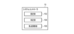
本実施形態に係るシステムコントローラ10のうち、焦点調節に係る機能を、図2に示す機能ブロック図を参照して説明する。図2に示すように、システムコントローラ10は、設定部102、判定部104及び焦点調節部106としての機能を有する。これらの機能は、CPU11、AF制御回路12、動きベクトル算出回路17等によって実現される。設定部102は、撮像素子24によって生成された撮像信号が表す撮像領域の内部に焦点検出領域を設定し、また、少なくとも一部が焦点検出領域に含まれる動き検出領域を設定する。判定部104は、動き検出領域の内部に係る動きについての被写体の不安定さを判定する。焦点調節部106は、焦点検出領域の内部についての合焦度を判定し、合焦度に基づいて焦点調節のためにレンズ群21に含まれるフォーカスレンズを移動させる焦点調節動作を行う。
In the system controller 10 according to the present embodiment, functions related to focus adjustment will be described with reference to a functional block diagram shown in FIG. As illustrated in FIG. 2, the system controller 10 has functions as a setting unit 102, a determination unit 104, and a focus adjustment unit 106. These functions are realized by the CPU 11, the AF control circuit 12, the motion vector calculation circuit 17, and the like. The setting unit 102 sets a focus detection area inside the imaging area represented by the imaging signal generated by the imaging element 24, and sets a motion detection area at least partially included in the focus detection area. The determination unit 104 determines instability of the subject with respect to the movement related to the inside of the motion detection area. The focus adjustment unit 106 determines a focus degree for the inside of the focus detection area, and performs a focus adjustment operation for moving a focus lens included in the lens group 21 for focus adjustment based on the focus degree.
[撮像装置の動作の概要]
本実施形態に係る撮像装置1のAFに係る動作の概要を説明する。本実施形態では、特に動画撮影中のAF動作について説明する。動画撮影においては、AF動作中のフォーカスレンズの動きが全て動画として記録されるので、特に見映えのよい安定したAF動作が求められる。撮像装置1では、AF動作のフェーズとして、3種類のフェーズが存在する。すなわち、微小駆動フェーズ(微小駆動;微小駆動動作)と、サーチフェーズ(サーチ;サーチ動作)と、待機フェーズ(待機;待機動作)とが存在する。 [Overview of operation of imaging device]
An outline of the operation related to AF of theimaging apparatus 1 according to the present embodiment will be described. In the present embodiment, an AF operation particularly during moving image shooting will be described. In moving image shooting, since all the movements of the focus lens during the AF operation are recorded as moving images, a particularly stable and stable AF operation is required. In the imaging apparatus 1, there are three types of phases as AF operation phases. That is, there are a minute drive phase (minute drive; minute drive operation), a search phase (search; search operation), and a standby phase (standby; standby operation).
本実施形態に係る撮像装置1のAFに係る動作の概要を説明する。本実施形態では、特に動画撮影中のAF動作について説明する。動画撮影においては、AF動作中のフォーカスレンズの動きが全て動画として記録されるので、特に見映えのよい安定したAF動作が求められる。撮像装置1では、AF動作のフェーズとして、3種類のフェーズが存在する。すなわち、微小駆動フェーズ(微小駆動;微小駆動動作)と、サーチフェーズ(サーチ;サーチ動作)と、待機フェーズ(待機;待機動作)とが存在する。 [Overview of operation of imaging device]
An outline of the operation related to AF of the
微小駆動フェーズにおいて行われるAF動作について図3及び図4を参照して説明する。微小駆動フェーズでは、フォーカスレンズは、例えば1フレーム毎に無限遠方向と至近方向とに交互に微小に動かされる。このような微小に往復させながら徐々に往復運動の中心位置を移動させることで、フォーカスの微調整が行われたり、合焦位置の方向の判定が行われたりする。このようなフォーカスレンズの動作を微小駆動動作と称することにする。なお、微小駆動動作はウォブリング動作とも呼ばれる。
AF operation performed in the minute drive phase will be described with reference to FIGS. In the minute driving phase, the focus lens is minutely moved alternately in the infinity direction and the closest direction, for example, every frame. By gradually moving the center position of the reciprocating motion while reciprocating slightly, the focus is finely adjusted or the direction of the in-focus position is determined. Such an operation of the focus lens will be referred to as a minute driving operation. Note that the minute driving operation is also called a wobbling operation.
図3は、微小駆動動作による合焦位置の方向の判定方法を説明するための図である。図3において、実線は、時間経過に対するレンズ位置の変化を示し、破線は、レンズ位置に対して得られる画像のコントラスト値を示す。図3の実線に示すように、レンズ位置が無限遠方向と至近方向とに交互に移動するとき、コントラスト値の変化が得られる。このコントラスト値の変化に基づいて、合焦位置の方向が判定され得る。無限遠方向と至近方向とのうち、コントラスト値が高くなる方向が合焦位置の方向である。
FIG. 3 is a diagram for explaining a method for determining the direction of the in-focus position by the minute driving operation. In FIG. 3, the solid line indicates the change in the lens position with time, and the broken line indicates the contrast value of the image obtained with respect to the lens position. As shown by the solid line in FIG. 3, when the lens position is moved alternately between the infinity direction and the close direction, a change in contrast value is obtained. Based on the change in the contrast value, the direction of the in-focus position can be determined. Of the infinity direction and the closest direction, the direction in which the contrast value increases is the direction of the in-focus position.
図4は、微小駆動動作によるフォーカスの微調整の方法について説明するための図である。図4において、実線は、時間経過に対するレンズ位置の変化を示し、破線は、レンズ位置に対して得られる画像のコントラスト値の変化を示す。フォーカスの微調整を行うとき、図4に示すように、無限遠方向と至近方向とに移動させるレンズ位置の変動の中心位置は徐々に移動する。この移動は、取得されたコントラスト値の情報に基づいて、コントラスト値が最大となるように行われる。この移動によって、フォーカスは、微調整される。
FIG. 4 is a diagram for explaining a method of finely adjusting the focus by a minute driving operation. In FIG. 4, the solid line indicates the change in the lens position with time, and the broken line indicates the change in the contrast value of the image obtained with respect to the lens position. When performing fine adjustment of the focus, as shown in FIG. 4, the center position of the fluctuation of the lens position to be moved in the infinity direction and the closest direction gradually moves. This movement is performed based on the acquired contrast value information so as to maximize the contrast value. By this movement, the focus is finely adjusted.
サーチフェーズにおいて行われるAF動作について図5を参照して説明する。図5において、実線は、時間経過に対するレンズ位置の変化を示し、破線は、レンズ位置に対して得られる画像のコントラスト値の変化を示す。サーチフェーズでは、フォーカスレンズは、一方向に連続的に移動する。このようなフォーカスレンズの駆動をスキャン駆動(サーチ動作)と称することにする。フォーカスレンズがスキャン駆動されているとき、その合焦度に応じてコントラスト値は変化する。スキャン駆動によっても、合焦位置が探索され得る。また、フォーカスレンズが一方向にしか移動しないので、スキャン駆動によるフォーカスレンズの移動は、微小駆動によるフォーカスレンズの移動よりも早い。
The AF operation performed in the search phase will be described with reference to FIG. In FIG. 5, the solid line indicates the change in the lens position with time, and the broken line indicates the change in the contrast value of the image obtained with respect to the lens position. In the search phase, the focus lens moves continuously in one direction. Such driving of the focus lens is referred to as scan driving (search operation). When the focus lens is driven to scan, the contrast value changes according to the degree of focus. The in-focus position can also be searched by scan driving. Further, since the focus lens moves only in one direction, the movement of the focus lens by scan driving is faster than the movement of the focus lens by minute driving.
待機フェーズは、レンズ駆動を行わず、被写体等の変化を監視する制御状態である。このようにレンズ駆動を行わずに合焦度を評価する状態を待機動作と称することにする。
The standby phase is a control state in which the lens is not driven and changes in the subject are monitored. Such a state in which the degree of focus is evaluated without driving the lens is referred to as a standby operation.
次にAF動作のフェーズの遷移について、図6を参照して説明する。本実施形態の撮像装置1は、動画撮影中において、動画AFとして、常に被写体に焦点を合わせるように動作する。この動画AFでは、撮像装置1は、制御フェーズを遷移させながら動作を継続する。前述のとおり、本実施形態に係る制御フェーズには、微小駆動フェーズ(微小駆動)と、サーチフェーズ(サーチ)と、待機フェーズ(待機)とがある。動画記録開始時は、微小駆動フェーズから制御が開始される。
Next, the transition of the phase of the AF operation will be described with reference to FIG. The imaging apparatus 1 of the present embodiment operates so as to always focus on a subject as moving image AF during moving image shooting. In this moving image AF, the imaging device 1 continues to operate while changing the control phase. As described above, the control phase according to the present embodiment includes a micro drive phase (micro drive), a search phase (search), and a standby phase (standby). At the start of moving image recording, control starts from the minute drive phase.
微小駆動フェーズにおいて、フォーカスレンズのレンズ位置が合焦位置から遠いと判断されたとき、すなわち、コントラスト値のピークが遠いと判断されたとき、動作フェーズはサーチフェーズに遷移する。サーチフェーズに遷移することによって、レンズ位置は素早く合焦位置へと移動する。一方、微小駆動フェーズにおいて、レンズ位置は合焦位置に到達したと判断されたとき、動作フェーズは待機フェーズに遷移し、レンズ駆動は止められる。
In the micro drive phase, when it is determined that the lens position of the focus lens is far from the in-focus position, that is, when it is determined that the peak of the contrast value is far, the operation phase shifts to the search phase. By shifting to the search phase, the lens position quickly moves to the in-focus position. On the other hand, when it is determined in the minute driving phase that the lens position has reached the in-focus position, the operation phase transitions to the standby phase, and the lens driving is stopped.
サーチフェーズにおいて、レンズ位置が合焦位置付近だと判定されたとき、すなわち、コントラスト値がピーク付近だと判断されたとき、動作フェーズは微小駆動フェーズに遷移する。この後、微小駆動動作によって、レンズ位置は合焦位置まで移動させられる。
In the search phase, when it is determined that the lens position is near the in-focus position, that is, when it is determined that the contrast value is near the peak, the operation phase shifts to the minute drive phase. Thereafter, the lens position is moved to the in-focus position by a minute driving operation.
待機フェーズにおいて、例えばジャイロセンサ回路28によって撮像装置1の動きが検出されたとき、画像におけるコントラスト値の変化や顔情報の変化があったとき等、すなわち、変化が検出されたとき、動作フェーズは微小駆動フェーズに遷移する。すなわち、合焦状態を維持するために、微小駆動動作が再開される。
In the standby phase, for example, when the movement of the imaging device 1 is detected by the gyro sensor circuit 28, when there is a change in contrast value or face information in the image, that is, when a change is detected, the operation phase is Transition to the micro drive phase. That is, the minute driving operation is resumed in order to maintain the in-focus state.
ここで、本実施形態で用いられるAFエリア群80について図7を参照して説明する。撮像領域89には、複数の焦点検出領域を含むAFエリア群80が設けられている。AFエリア群80には、中エリア82と、9個の小エリア83とが含まれる。ここで、小エリア83のうち、上段左側、上段中央、上段右側、中段左側、中段中央、中段右側、下段左側、下段中央及び下段右側のエリアをそれぞれ、第1の小エリア91、第2の小エリア92、第3の小エリア93、第4の小エリア94、第5の小エリア95、第6の小エリア96、第7の小エリア97、第8の小エリア98及び第9の小エリア99と称することにする。中エリア82、及び9個の小エリア83の合計10個の焦点検出領域であるAFエリアが組み合わされて用いられることで、様々な被写体に対して適当なAF動作が行われ得る。
Here, the AF area group 80 used in this embodiment will be described with reference to FIG. The imaging area 89 is provided with an AF area group 80 including a plurality of focus detection areas. The AF area group 80 includes a middle area 82 and nine small areas 83. Here, of the small areas 83, the upper left area, upper middle area, upper right area, middle left area, middle middle area, middle right area, lower left area, lower middle area, and lower right area are designated as the first small area 91 and the second lower area, respectively. Small area 92, third small area 93, fourth small area 94, fifth small area 95, sixth small area 96, seventh small area 97, eighth small area 98, and ninth small area This will be referred to as area 99. By using a combination of AF areas, which are a total of 10 focus detection areas including the middle area 82 and the nine small areas 83, an appropriate AF operation can be performed on various subjects.
次に、動きベクトルの検出について図8を参照して説明する。動きベクトルとは、連続撮影によって得られた連続した画像において、前の画像にある特徴点と相関の強い特徴点を後の画像において探索することで得られる、特徴点の移動方向及び移動量を表すベクトルである。動きベクトルの決定には、動き検出領域としての動きベクトル検出エリア71が用いられる。図8において、破線で示す人物78は、連続する前後の画像のうち前の画像の注目被写体の位置を示し、実線で示す人物79は、連続する前後の画像のうち後の画像の注目被写体の位置を示す。動きベクトル検出エリア71は、その中央部に配置された評価エリア72と、評価エリア72の周囲に設けられた探索エリア73とを含む。動きベクトルの決定では、前の画像において評価エリア72の画像を特徴点として指定し、当該特徴点と相関の強い特徴点を後の画像における探索エリア73内で探索する。前の画像の評価エリア72と後の画像において探索された特徴点とを結ぶベクトルが動きベクトルとなる。本実施形態では、動きベクトルが被写体の安定性の評価に利用される。
Next, motion vector detection will be described with reference to FIG. A motion vector refers to a moving direction and a moving amount of a feature point obtained by searching a subsequent image for a feature point having a strong correlation with a feature point in a previous image in a continuous image obtained by continuous shooting. It is a vector that represents. For the determination of the motion vector, a motion vector detection area 71 as a motion detection area is used. In FIG. 8, a person 78 indicated by a broken line indicates the position of the subject of interest of the previous image among consecutive images before and after, and a person 79 indicated by a solid line indicates the subject of interest of the subsequent image among consecutive images. Indicates the position. The motion vector detection area 71 includes an evaluation area 72 arranged at the center thereof and a search area 73 provided around the evaluation area 72. In determining the motion vector, the image in the evaluation area 72 is designated as a feature point in the previous image, and a feature point having a strong correlation with the feature point is searched in the search area 73 in the subsequent image. A vector connecting the evaluation area 72 of the previous image and the feature point searched for in the subsequent image is a motion vector. In the present embodiment, the motion vector is used for evaluating the stability of the subject.
動きベクトル検出エリア71の配置について図9を参照して説明する。本実施形態では、上述の中エリア82又は小エリア83としてのAFエリア81の位置に応じて動きベクトル検出エリア71が設定される。動きベクトル検出エリア71は、AFエリア81内を広くカバーできることが望ましい。AFエリア81内で動きベクトル検出エリア71がカバーしている範囲が狭いと、AF評価値であるコントラスト値に影響を与えるような被写体の動きを検出できない可能性がある。一方で、AFエリア81の外まで動きベクトル検出エリア71を広げてもよいが、AF評価値に直接的に影響を与えない被写体の動きまで検出してしまうことがないように配慮する必要がある。本実施形態では、動きベクトル検出エリア71は、1つのAFエリア81内に複数設けられる。例えば、図9に示すように、4行×4列に合計16個の動きベクトル検出エリア71が1つのAFエリア81内に設けられる。1個の動きベクトル検出エリア71が小さく、エリア数が多いほど、被写体の細かい動きを検出することができる。しかしながら、その分、演算負荷は大きくなるため、動きベクトル算出回路17の処理能力と必要な検出精度とを考慮して動きベクトル検出エリア71の大きさ及び数は設定される。
The arrangement of the motion vector detection area 71 will be described with reference to FIG. In the present embodiment, the motion vector detection area 71 is set according to the position of the AF area 81 as the middle area 82 or the small area 83 described above. It is desirable that the motion vector detection area 71 can cover the AF area 81 widely. If the range covered by the motion vector detection area 71 in the AF area 81 is narrow, there is a possibility that the movement of the subject that affects the contrast value that is the AF evaluation value cannot be detected. On the other hand, although the motion vector detection area 71 may be extended outside the AF area 81, it is necessary to take care not to detect a subject motion that does not directly affect the AF evaluation value. . In the present embodiment, a plurality of motion vector detection areas 71 are provided in one AF area 81. For example, as shown in FIG. 9, a total of 16 motion vector detection areas 71 are provided in one AF area 81 in 4 rows × 4 columns. As one motion vector detection area 71 is smaller and the number of areas is larger, the fine motion of the subject can be detected. However, since the calculation load increases accordingly, the size and number of motion vector detection areas 71 are set in consideration of the processing capability of the motion vector calculation circuit 17 and the required detection accuracy.
[撮像装置のAF動作]
撮像装置1の微小駆動フェーズにおけるAFに係る動作について説明する。図10は、動画撮影中の微小駆動制御処理の一例の概略を示す図である。 [AF operation of imaging device]
An operation related to AF in the minute driving phase of theimaging apparatus 1 will be described. FIG. 10 is a diagram illustrating an outline of an example of a minute drive control process during moving image shooting.
撮像装置1の微小駆動フェーズにおけるAFに係る動作について説明する。図10は、動画撮影中の微小駆動制御処理の一例の概略を示す図である。 [AF operation of imaging device]
An operation related to AF in the minute driving phase of the
ステップS101において、CPU11は、動画記録が開始されたか否かを判定する。例えば、カメラ操作スイッチ27のうちの1つである録画ボタンが押されたとき、動画記録が開始される。動画記録が開始されていないと判定されたとき、処理はステップS101を繰り返して待機する。一方、動画記録が開始されたと判定されたとき、処理はステップS102に進む。なお、動画記録が開始されると、撮像素子24は、フォーカスレンズを含むレンズ群21を介して被写体からの光を受光して、撮像信号を生成する。この撮像信号は、画像処理回路14で画像処理され、記録メディア43に記録されたり、表示素子25に表示されたりする。
In step S101, the CPU 11 determines whether moving image recording has been started. For example, when a recording button which is one of the camera operation switches 27 is pressed, moving image recording is started. When it is determined that moving image recording has not started, the process repeats step S101 and waits. On the other hand, when it is determined that moving image recording has started, the process proceeds to step S102. When moving image recording is started, the image sensor 24 receives light from the subject via the lens group 21 including the focus lens and generates an image signal. The imaging signal is subjected to image processing by the image processing circuit 14 and is recorded on the recording medium 43 or displayed on the display element 25.
ステップS102において、システムコントローラ10は、被写体不安定判定処理を行う。被写体不安定判定処理は、後に詳述するが、被写体の状態が、「安定」であるか、「不安定」であるか、「安定確定待ち」であるかを判定する処理である。
In step S102, the system controller 10 performs subject instability determination processing. The subject instability determination process, which will be described in detail later, is a process for determining whether the state of the subject is “stable”, “unstable”, or “waiting for stability determination”.
ステップS103において、システムコントローラ10は、AF制御処理を行う。AF制御処理は、後に詳述するが、被写体の合焦状態を求め、合焦させるために必要なレンズ群21に含まれるフォーカスレンズの移動方向及び移動量を求め、フォーカスレンズを移動させる処理である。
In step S103, the system controller 10 performs AF control processing. As will be described in detail later, the AF control process is a process for obtaining the in-focus state of the subject, obtaining the moving direction and moving amount of the focus lens included in the lens group 21 necessary for focusing, and moving the focus lens. is there.
ステップS104において、CPU11は、動画記録が終了されたか否かを判定する。例えば、録画ボタンが再び押されたとき、動画記録が終了する。動画記録が終了されていないと判定されたとき、処理はステップS102に戻り、被写体不安定判定処理及びAF制御処理が繰り返される。このステップS102乃至ステップS104の繰り返し処理は、例えば動画撮影の1フレーム毎に行われる。一方、動画記録が終了されたと判定されたとき、微小駆動制御処理は終了する。
In step S104, the CPU 11 determines whether the moving image recording has been completed. For example, when the recording button is pressed again, the moving image recording ends. When it is determined that the moving image recording has not ended, the process returns to step S102, and the subject instability determination process and the AF control process are repeated. The repetitive processing from step S102 to step S104 is performed for each frame of moving image shooting, for example. On the other hand, when it is determined that the moving image recording is finished, the minute drive control process is finished.
ステップS102で行われる被写体不安定判定処理について図11を参照して説明する。被写体の不安定さに係る状態として、「安定」、「不安定」、「安定確定待ち」の3つの状態を定義する。ここで、安定状態とは、被写体が安定している状態である。判定開始時は安定状態とする。不安定状態とは、被写体が不安定な状態である。安定状態において、動きベクトルが不安定化したとき、状態は不安定状態に遷移する。安定確定待ち状態とは、不安定だった被写体が安定して間もない状態である。すなわち、不安定状態において、動きベクトルが安定化したとき、状態は安定確定待ち状態に遷移する。安定確定待ち状態において、動きベクトルが不安定化したとき、状態は不安定状態に遷移する。安定確定待ち状態において、動きベクトルが安定のまま所定期間が経過したら、状態は安定状態に遷移する。被写体不安定判定処理では、被写体の不安定さが安定、不安定及び安定確定待ちのうち何れの状態であるかを決定する。本実施形態では、被写体の不安定さが安定と判定された場合のみ、AF動作が行われる。なお、AFの安定性よりも追従性を重視したい場合には、安定確定待ちでもAF動作をするようにしてもよい。
The subject instability determination process performed in step S102 will be described with reference to FIG. Three states of “stable”, “unstable”, and “waiting for stability confirmation” are defined as states relating to instability of the subject. Here, the stable state is a state where the subject is stable. A stable state is assumed at the start of judgment. The unstable state is a state where the subject is unstable. When the motion vector becomes unstable in the stable state, the state transitions to the unstable state. The stabilization waiting state is a state in which an unstable subject is stable and shortly after. That is, when the motion vector is stabilized in the unstable state, the state transitions to the stability determination waiting state. When the motion vector becomes unstable in the stability determination waiting state, the state transitions to an unstable state. If a predetermined period of time elapses while the motion vector is stable in the stability determination waiting state, the state transitions to the stable state. In the subject instability determination process, it is determined whether the subject instability is stable, unstable, or waiting for stability confirmation. In the present embodiment, the AF operation is performed only when it is determined that the instability of the subject is stable. If it is desired to emphasize followability rather than AF stability, the AF operation may be performed even while waiting for stability confirmation.
被写体不安定判定処理について、図12に示すフローチャートを参照して説明する。ステップS201乃至ステップS204の処理は、4行×4列に合計16個ある動きベクトル検出エリア71についてそれぞれ行われる繰り返し処理であり、動きベクトルに係る演算である。
The subject instability determination process will be described with reference to the flowchart shown in FIG. The processing from step S201 to step S204 is an iterative process performed for each of the 16 motion vector detection areas 71 in a total of 4 rows × 4 columns, and is an operation related to motion vectors.
ステップS201において、動きベクトル算出回路17は、動きベクトル絶対値算出処理を行う。すなわち、動きベクトル算出回路17は、X方向の動きベクトルの値とY方向の動きベクトルの値とについて、それぞれ絶対値をとり、これら絶対値を足し合わせる。このようにして得られた値を、被写体の不安定さを評価する不安定評価値とする。すなわち、ある動きベクトル検出エリアareaにおけるX方向動きベクトルをvec_x[area]とし、Y方向動きベクトルをvec_y[area]とし、絶対値を取る関数をabs(X)としたときに、不安定評価値unstable_val[area]は、
unstable_val[area] = abs(vec_x[area]) + abs(vec_y[area])
で表される。不安定評価値は、被写体の不安定さを判定するための値であるため、X方向とY方向の動きベクトルの値の絶対値をとって足し合わせることとした。 In step S201, the motionvector calculation circuit 17 performs a motion vector absolute value calculation process. That is, the motion vector calculation circuit 17 takes absolute values for the value of the motion vector in the X direction and the value of the motion vector in the Y direction, and adds these absolute values. The value thus obtained is used as an instability evaluation value for evaluating the instability of the subject. That is, when the X-direction motion vector in a certain motion vector detection area area is vec_x [area], the Y-direction motion vector is vec_y [area], and the function that takes an absolute value is abs (X), the unstable evaluation value unstable_val [area] is
unstable_val [area] = abs (vec_x [area]) + abs (vec_y [area])
It is represented by Since the instability evaluation value is a value for determining instability of the subject, the absolute value of the motion vector values in the X direction and the Y direction is taken and added.
unstable_val[area] = abs(vec_x[area]) + abs(vec_y[area])
で表される。不安定評価値は、被写体の不安定さを判定するための値であるため、X方向とY方向の動きベクトルの値の絶対値をとって足し合わせることとした。 In step S201, the motion
unstable_val [area] = abs (vec_x [area]) + abs (vec_y [area])
It is represented by Since the instability evaluation value is a value for determining instability of the subject, the absolute value of the motion vector values in the X direction and the Y direction is taken and added.
なお、例えば撮像素子24に被写体像の位相差を検出するための位相差画素が配置されており、位相差画素の出力に基づいて位相差が算出される撮像装置1においては、この位相差に基づいて、撮像装置1から被写体までの距離が求められる。そこで、この場合、算出された測距値(デプスデータ)のフレーム間の差分を奥行き方向の動きベクトルとし、X方向及びY方向の動きベクトルと併せて同様の演算が行われてもよい。
For example, in the imaging device 1 in which a phase difference pixel for detecting the phase difference of the subject image is arranged in the imaging element 24 and the phase difference is calculated based on the output of the phase difference pixel, this phase difference is included. Based on this, the distance from the imaging device 1 to the subject is obtained. Therefore, in this case, the difference between the calculated distance values (depth data) between frames may be used as a motion vector in the depth direction, and the same calculation may be performed together with the motion vectors in the X direction and the Y direction.
ステップS202において、動きベクトル算出回路17は、動きベクトル非採用判定処理を行う。すなわち、本実施形態では、動きベクトル算出回路17は、動きベクトルの検出結果の信頼性が低いとき、当該動きベクトルの検出結果を判定に反映しない。また、動きベクトル算出回路17は、被写体又は撮像装置1の状態が所定の条件を満たす場合においては、動きベクトル情報を用いない。より具体的には、以下の(1)乃至(3)の条件を用いる。
(1)動きベクトル検出エリア内の被写体のコントラストが低いと判断されるとき
(2)動きベクトル検出エリア内の被写体が周期性被写体であると判断されるとき
(3)ジャイロセンサ回路28で撮像装置1の動きを検出中であるとき
条件(1)乃至(3)の何れかを満たすとき、動きベクトルを非採用とし、不安定評価値unstable_val[area]を0に設定する。条件(1)乃至(3)の何れをも満たさないとき、動きベクトルを採用とし、ステップS201で算出された値を不安定評価値unstable_val[area]に決定する。 In step S202, the motionvector calculation circuit 17 performs motion vector non-adoption determination processing. That is, in the present embodiment, the motion vector calculation circuit 17 does not reflect the motion vector detection result in the determination when the reliability of the motion vector detection result is low. The motion vector calculation circuit 17 does not use motion vector information when the subject or the state of the imaging device 1 satisfies a predetermined condition. More specifically, the following conditions (1) to (3) are used.
(1) When it is determined that the contrast of the subject in the motion vector detection area is low (2) When it is determined that the subject in the motion vector detection area is a periodic subject (3) The imaging device with thegyro sensor circuit 28 When motion of 1 is being detected When any of the conditions (1) to (3) is satisfied, the motion vector is not adopted, and the unstable evaluation value unstable_val [area] is set to 0. When none of the conditions (1) to (3) is satisfied, the motion vector is adopted, and the value calculated in step S201 is determined as the unstable evaluation value unstable_val [area].
(1)動きベクトル検出エリア内の被写体のコントラストが低いと判断されるとき
(2)動きベクトル検出エリア内の被写体が周期性被写体であると判断されるとき
(3)ジャイロセンサ回路28で撮像装置1の動きを検出中であるとき
条件(1)乃至(3)の何れかを満たすとき、動きベクトルを非採用とし、不安定評価値unstable_val[area]を0に設定する。条件(1)乃至(3)の何れをも満たさないとき、動きベクトルを採用とし、ステップS201で算出された値を不安定評価値unstable_val[area]に決定する。 In step S202, the motion
(1) When it is determined that the contrast of the subject in the motion vector detection area is low (2) When it is determined that the subject in the motion vector detection area is a periodic subject (3) The imaging device with the
条件(1)としての動きベクトル検出エリア71内の被写体のコントラストが低いと判断されるときは、動きベクトル検出の信頼性が低い。信頼性が低い値に基づいて処理を行うことは好ましくないため、不安定評価値unstable_val[area]を0に設定する。また、被写体のコントラストが低いときは、デフォーカス状態で被写体がボケている可能性がある。このような場合に、不安定であると評価されてAF動作が停止されることは好ましくないため、不安定評価値unstable_val[area]を0に設定する。
When it is determined that the contrast of the subject in the motion vector detection area 71 as the condition (1) is low, the reliability of the motion vector detection is low. Since it is not preferable to perform processing based on a value with low reliability, the unstable evaluation value unstable_val [area] is set to zero. When the contrast of the subject is low, the subject may be blurred in the defocused state. In such a case, since it is not preferable that the AF operation is stopped because it is evaluated as unstable, the unstable evaluation value unstable_val [area] is set to zero.
条件(2)としての動きベクトル検出エリア71内の被写体が周期性被写体であると判断されるときは、動きベクトル検出の信頼性が低い。すなわち、周期性被写体を対象とする場合、特徴点と相関の強い点が複数検出され得る。このため、動きベクトル検出の信頼性が低くなる。被写体が周期性を有しているか否かの判定方法としては、エリア内の特徴点の相関値のバラつきが大きいときに被写体が周期性を有していると判定する方法が知られている。
When it is determined that the subject in the motion vector detection area 71 as the condition (2) is a periodic subject, the reliability of motion vector detection is low. That is, when a periodic subject is targeted, a plurality of points having strong correlation with feature points can be detected. For this reason, the reliability of motion vector detection becomes low. As a method for determining whether or not a subject has periodicity, there is known a method for determining that a subject has periodicity when the correlation value of feature points in an area has a large variation.
条件(3)としてのジャイロセンサ回路28で動きを検出中であるとき、撮像装置1の動きに応じて被写体が変化するので、動きベクトルも検出される。しかしながら、ユーザが撮像装置1を動かしているときは、ユーザが動く被写体を追っている最中である可能性も高い。動く被写体を追っているときは、多少不安定さがあっても積極的にAF動作を行いたいので、不安定評価値unstable_val[area]を0に設定する。
When the motion is being detected by the gyro sensor circuit 28 as the condition (3), the subject changes in accordance with the motion of the imaging device 1, so that the motion vector is also detected. However, when the user is moving the imaging apparatus 1, there is a high possibility that the user is chasing a moving subject. When chasing a moving subject, the instability evaluation value unstable_val [area] is set to 0 because the AF operation is to be performed actively even if there is some instability.
ステップS203において、動きベクトル算出回路17は、動きベクトル履歴加算演算処理を行う。すなわち、動きベクトル算出回路17は、所定フレーム分の不安定評価値unstable_val[area]を加算し、合計値である履歴加算値を算出する。ここで、加算するフレーム数は、例えば8フレームである。この履歴加算により、動きベクトルの誤検出による影響を低減する。
In step S203, the motion vector calculation circuit 17 performs motion vector history addition calculation processing. That is, the motion vector calculation circuit 17 adds the unstable evaluation value unstable_val [area] for a predetermined frame to calculate a history addition value that is a total value. Here, the number of frames to be added is, for example, 8 frames. This history addition reduces the influence caused by erroneous detection of motion vectors.
ステップS204において、動きベクトル算出回路17は、不安定エリア判定処理を行う。ステップS203で算出された履歴加算値が所定の閾値を超えたとき、動きベクトル算出回路17は、当該動きベクトル検出エリア71の被写体は不安定であると判定する。不安定であると判定されたとき、動きベクトル算出回路17は、不安定エリアカウントをインクリメントする。不安定エリアカウントは、複数ある動きベクトル検出エリア71のうち被写体が不安定であると判定された動きベクトル検出エリア71の数を数えるための値である。動きベクトル検出エリア71の被写体は不安定でないと判定されたとき、動きベクトル算出回路17は、不安定エリアカウントを変更しない。
In step S204, the motion vector calculation circuit 17 performs unstable area determination processing. When the history addition value calculated in step S203 exceeds a predetermined threshold value, the motion vector calculation circuit 17 determines that the subject in the motion vector detection area 71 is unstable. When it is determined to be unstable, the motion vector calculation circuit 17 increments the unstable area count. The unstable area count is a value for counting the number of motion vector detection areas 71 in which the subject is determined to be unstable among the plurality of motion vector detection areas 71. When it is determined that the subject in the motion vector detection area 71 is not unstable, the motion vector calculation circuit 17 does not change the unstable area count.
ステップS201乃至ステップS204の処理が全ての動きベクトル検出エリア71について行われると、被写体が不安定であると判定された動きベクトル検出エリア71の数が不安定エリアカウントとして求まる。
When the processing from step S201 to step S204 is performed for all the motion vector detection areas 71, the number of motion vector detection areas 71 determined that the subject is unstable is obtained as the unstable area count.
ステップS205において、CPU11は、不安定エリアカウントを用いて不安定状態更新処理を行う。不安定状態更新処理について図13に示すフローチャートを参照して説明する。
In step S205, the CPU 11 performs an unstable state update process using the unstable area count. The unstable state update process will be described with reference to the flowchart shown in FIG.
ステップS301において、CPU11は、不安定エリアカウントが所定の閾値より大きいか否かを判定する。例えば動きベクトル検出エリア71の数が上述のとおり16であるとき、閾値は例えば2に設定される。不安定エリアカウントが閾値より大きいとき、処理はステップS302に進む。ステップS302において、CPU11は、被写体の不安定さを表す不安定状態パラメータを「不安定」に設定する。ステップS303において、CPU11は、安定確定待ちの期間を計るためのHISカウンタを0にクリアする。以上で不安定状態更新処理は終了する。
In step S301, the CPU 11 determines whether or not the unstable area count is greater than a predetermined threshold value. For example, when the number of motion vector detection areas 71 is 16, as described above, the threshold is set to 2, for example. When the unstable area count is larger than the threshold value, the process proceeds to step S302. In step S <b> 302, the CPU 11 sets the unstable state parameter indicating the instability of the subject to “unstable”. In step S <b> 303, the CPU 11 clears the HIS counter for measuring the stabilization waiting period to 0. Thus, the unstable state update process ends.
ステップS301において、不安定エリアカウントが閾値より大きくないと判定されたとき、処理はステップS304に進む。ステップS304において、CPU11は、被写体は安定しているか否かを判定する。ここで、現在の不安定状態パラメータが「安定」に設定されているとき、安定であると判定される。また、HISカウンタの値が所定の閾値よりも大きくなったとき、被写体がしっかりと安定したと考えられ、被写体は安定であると判定される。ここで所定の閾値は例えば5である。安定であると判定されたとき、処理はステップS305に進む。ステップS305において、CPU11は、不安定状態パラメータを「安定」に設定する。ステップS306において、CPU11は、HISカウンタを0にクリアする。以上で不安定状態更新処理は終了する。
If it is determined in step S301 that the unstable area count is not greater than the threshold, the process proceeds to step S304. In step S304, the CPU 11 determines whether or not the subject is stable. Here, when the current unstable state parameter is set to “stable”, it is determined to be stable. Further, when the value of the HIS counter becomes larger than a predetermined threshold value, it is considered that the subject is firmly stabilized, and it is determined that the subject is stable. Here, the predetermined threshold is 5, for example. When it is determined to be stable, the process proceeds to step S305. In step S305, the CPU 11 sets the unstable state parameter to “stable”. In step S306, the CPU 11 clears the HIS counter to zero. Thus, the unstable state update process ends.
ステップS304において安定していないと判定されたとき、処理はステップS307に進む。このとき、被写体はまだしっかりと安定しきっていない可能性がある。そこで、ステップS307において、CPU11は、不安定状態パラメータを「安定確定待ち」に設定する。ステップS308において、CPU11は、HISカウンタをインクリメントする。以上で不安定状態更新処理は終了する。
When it is determined in step S304 that it is not stable, the process proceeds to step S307. At this time, there is a possibility that the subject is not yet firmly stabilized. Therefore, in step S307, the CPU 11 sets the unstable state parameter to “waiting for stable determination”. In step S308, the CPU 11 increments the HIS counter. Thus, the unstable state update process ends.
被写体不安定判定処理によって、不安定状態パラメータは、「安定」、「不安定」又は「安定確定待ち」の何れかに決定される。ここで本実施形態では、不安定エリア数が閾値を超えた状態から閾値以下に変化したとき、HISカウンタの値が閾値を超えるまで、不安定状態パラメータは「安定確定待ち」に設定され、HISカウンタの値が閾値を超えたとき、不安定状態パラメータは「安定」に設定される。このように、不安定状態から安定状態への状態遷移に猶予期間が設けられている。このような猶予期間が設けられることで、不安定状態パラメータが安定と不安定とで交互に連続的に切り換わることが防止される。
By the subject instability determination process, the unstable state parameter is determined as “stable”, “unstable”, or “waiting for stability determination”. Here, in this embodiment, when the number of unstable areas changes from a state exceeding the threshold value to a threshold value or less, the unstable state parameter is set to “waiting for stable determination” until the value of the HIS counter exceeds the threshold value. When the value of the counter exceeds the threshold value, the unstable state parameter is set to “stable”. Thus, a grace period is provided for the state transition from the unstable state to the stable state. By providing such a grace period, it is possible to prevent the unstable state parameter from being continuously switched alternately between stable and unstable.
ステップS103で行われるAF制御処理について、図14に示すフローチャートを参照して説明する。
The AF control process performed in step S103 will be described with reference to the flowchart shown in FIG.
ステップS401において、AF制御回路12は、ステップS102で決定された不安定状態について、現在の被写体の不安定状態パラメータが安定であるか否かを判定する。安定であると判定されたとき、処理はステップS402に進む。
In step S401, the AF control circuit 12 determines whether or not the current unstable state parameter of the subject is stable for the unstable state determined in step S102. If it is determined to be stable, the process proceeds to step S402.
ステップS402において、AF制御回路12は、被写体の不安定状態パラメータが安定となった直後であるか否かを判定する。ここで、不安定状態パラメータが安定に変化して初めてのステップS402の判定であったり、後述する合焦状態確認処理を継続中であったりする場合に、安定となった直後であると判定される。ステップS402では、不安定状態パラメータが前回は安定確定待ちであり、今回は安定であることを判別することで、安定に変化して初めてと判定する。また、合焦状態確認処理継続のフラグを参照して1であれば継続中と判定する。安定となった直後であるとき、処理はステップS403に進む。
In step S402, the AF control circuit 12 determines whether or not it is immediately after the unstable state parameter of the subject becomes stable. Here, when the determination in step S402 is performed for the first time after the unstable state parameter is stably changed, or when an in-focus state confirmation process to be described later is being continued, it is determined that the state is immediately after becoming stable. The In step S <b> 402, it is determined that the unstable state parameter is changed only stably by determining that the unstable state parameter is waiting for stability determination last time and is stable this time. In addition, referring to the in-focus state confirmation processing flag, if it is 1, it is determined that it is continuing. If it is immediately after becoming stable, the process proceeds to step S403.
ステップS403において、AF制御回路12は、合焦状態確認処理を行う。合焦状態確認処理は、被写体の不安定状態パラメータが安定確定待ちから安定に変化したとき、つまり被写体が不安定な状態から安定な状態に変化したとき、被写体が変化している可能性があるので、被写体が変化しているかを確認し、また、合焦状態を確認する処理である。
In step S403, the AF control circuit 12 performs an in-focus state confirmation process. In-focus state confirmation processing, the subject may have changed when the subject's instability parameter has changed stably from waiting for stability confirmation, that is, when the subject has changed from an unstable state to a stable state. Therefore, it is processing for confirming whether the subject has changed and confirming the in-focus state.
合焦状態確認処理では、その他の動作の場合と比べてフォーカスレンズを大きく移動させる。被写体が不安定な状態から安定な状態に遷移して間もない状態であるので、多少合焦位置が大きく動いても動画の見映えに対して与える影響は相対的に小さくなる。このため、フォーカスレンズの移動量を比較的大きくすることができる。
In the in-focus state confirmation process, the focus lens is moved largely compared to other operations. Since the subject is in a state just after the transition from the unstable state to the stable state, the influence on the appearance of the moving image is relatively small even if the in-focus position is slightly moved. For this reason, the amount of movement of the focus lens can be made relatively large.
合焦状態確認処理について、図15に示すフローチャートを参照して説明する。
The focused state confirmation processing will be described with reference to the flowchart shown in FIG.
ステップS501において、AF制御回路12は、現在用いているAFエリア81のサイズに比較して、主要被写体が小さい可能性があるか否かを判定する。AFエリア81に比べて主要被写体が小さいとき、AFエリア81内に主要被写体と背景とが混在してしまう。その結果、フォーカスレンズの位置が背景に合焦するように固定されてしまい、主要被写体に合焦しないおそれがある。一方で、主要被写体に比べてAFエリア81が小さいと、コントラスト情報が被写体ブレや手ブレ等の影響を受けやすくなり、AF動作が不安定になってしまうおそれがある。そこで、本実施形態では、主要被写体が小さいときにのみ、AFエリア81が小さく設定される。AFエリア81のサイズに比べて主要被写体が小さいと判定されたとき、処理はステップS502に進む。ステップS502において、AF制御回路12は、被写体は小被写体であると確定する。その後、処理はステップS509に進む。
In step S501, the AF control circuit 12 determines whether or not there is a possibility that the main subject is small compared to the size of the AF area 81 currently used. When the main subject is smaller than the AF area 81, the main subject and the background are mixed in the AF area 81. As a result, the position of the focus lens is fixed so as to focus on the background, and the main subject may not be focused. On the other hand, if the AF area 81 is smaller than the main subject, the contrast information is likely to be affected by subject blur, camera shake, and the like, and the AF operation may become unstable. Therefore, in the present embodiment, the AF area 81 is set small only when the main subject is small. If it is determined that the main subject is smaller than the size of the AF area 81, the process proceeds to step S502. In step S502, the AF control circuit 12 determines that the subject is a small subject. Thereafter, the process proceeds to step S509.
主要被写体が小さいか否かの判断は、例えば次のように行ってもよい。すなわち、例えば第5の小エリア95と中エリア82のように、一方のエリアが他方のエリアを含んでいて面積が異なるAFエリア81のそれぞれに基づいて、合焦するためにフォーカスレンズを移動させるべき方向を算出する。AFエリア81の面積が異なると得られるフォーカスレンズの移動方向が逆向きとなるとき、主要被写体は小被写体であると決定することができる。このときは主要被写体と背景が混在している可能性が高い。
The determination as to whether or not the main subject is small may be performed as follows, for example. That is, for example, like the fifth small area 95 and the middle area 82, the focus lens is moved for focusing based on each of the AF areas 81 that include the other area and have different areas. Calculate the power direction. When the movement direction of the focus lens obtained when the areas of the AF area 81 are different is reversed, the main subject can be determined to be a small subject. At this time, there is a high possibility that the main subject and the background are mixed.
ステップS501においてAFエリア81のサイズに比べて主要被写体が小さくないと判定されたとき、処理はステップS503に進む。ステップS503において、AF制御回路12は、被写体の状態が安定したときに既に焦点位置は合焦付近であるか否かを判定する。焦点位置が合焦付近であるときは、フォーカスレンズの移動量を小さめに抑えることで、焦点位置変化のちらつきを目立ちにくくすることが好ましい。例えば次の3つの条件のうち、何れかを満たすとき、焦点位置が合焦付近であると判定する。
(1)AF評価値(コントラスト値)の絶対値が所定の値以上であること
(2)カットオフ周波数が高いハイパスフィルタを通過したコントラスト値で所定値より大きなコントラスト値の変化が検出されていること
(3)撮像素子24に位相差検出画素が設けられている場合等において、位相差に基づき算出されたデフォーカス量が所定値以内であること
焦点位置は合焦位置付近であると判定されたとき、処理はステップS504に進む。ステップS504において、AF制御回路12は、焦点位置は合焦位置付近であると確定する。その後、処理はステップS509に進む。 If it is determined in step S501 that the main subject is not smaller than the size of theAF area 81, the process proceeds to step S503. In step S503, the AF control circuit 12 determines whether or not the focal position is already in the focus when the state of the subject is stabilized. When the focal position is near the in-focus position, it is preferable to make the change in the focal position inconspicuous by suppressing the moving amount of the focus lens to be small. For example, when any one of the following three conditions is satisfied, it is determined that the focal position is near the in-focus position.
(1) The absolute value of the AF evaluation value (contrast value) is greater than or equal to a predetermined value. (2) A change in contrast value greater than the predetermined value is detected in the contrast value that has passed through the high-pass filter having a high cutoff frequency. (3) When a phase difference detection pixel is provided in theimage sensor 24, the defocus amount calculated based on the phase difference is within a predetermined value. It is determined that the focal position is near the in-focus position. If so, the process proceeds to step S504. In step S504, the AF control circuit 12 determines that the focal position is near the in-focus position. Thereafter, the process proceeds to step S509.
(1)AF評価値(コントラスト値)の絶対値が所定の値以上であること
(2)カットオフ周波数が高いハイパスフィルタを通過したコントラスト値で所定値より大きなコントラスト値の変化が検出されていること
(3)撮像素子24に位相差検出画素が設けられている場合等において、位相差に基づき算出されたデフォーカス量が所定値以内であること
焦点位置は合焦位置付近であると判定されたとき、処理はステップS504に進む。ステップS504において、AF制御回路12は、焦点位置は合焦位置付近であると確定する。その後、処理はステップS509に進む。 If it is determined in step S501 that the main subject is not smaller than the size of the
(1) The absolute value of the AF evaluation value (contrast value) is greater than or equal to a predetermined value. (2) A change in contrast value greater than the predetermined value is detected in the contrast value that has passed through the high-pass filter having a high cutoff frequency. (3) When a phase difference detection pixel is provided in the
ステップS503において焦点位置は合焦位置付近でないと判定されたとき、処理はステップS505に進む。ステップS505において、AF制御回路12は、合焦状態確認継続カウンタをインクリメントする。その後、処理はステップS506に進む。なお、合焦状態確認継続カウンタ、合焦状態確認継続フラグは、微小駆動制御処理の最初で初期化されている。
When it is determined in step S503 that the focal position is not near the in-focus position, the process proceeds to step S505. In step S505, the AF control circuit 12 increments the in-focus state confirmation continuation counter. Thereafter, the process proceeds to step S506. The in-focus state check continuation counter and the in-focus state check continuation flag are initialized at the beginning of the minute drive control process.
ステップS506において、AF制御回路12は、合焦状態確認継続カウンタの値が所定の閾値よりも大きいか否かを判定する。被写体は小被写体であるとも焦点位置は合焦位置付近だとも確定されずに所定期間が経過したとき、被写体に非合焦の状態又は何かしらイレギュラーなことが発生している状態だと推測される。合焦状態確認継続カウンタの値が所定の閾値よりも大きいとき、処理はステップS507に進む。ステップS507において、AF制御回路12は、デフォーカス状態であると確定する。また、合焦状態確認継続カウンタと合焦状態確認継続フラグがクリアされる。その後、処理はステップS509に進む。
In step S506, the AF control circuit 12 determines whether or not the value of the in-focus state confirmation continuation counter is greater than a predetermined threshold value. Whether the subject is a small subject or the focal position is near the in-focus position, it is assumed that the subject is in an out-of-focus state or something irregular occurs when a predetermined period has passed. The When the value of the focused state confirmation continuation counter is larger than the predetermined threshold, the process proceeds to step S507. In step S507, the AF control circuit 12 determines that it is in the defocused state. Further, the focus state confirmation continuation counter and the focus state confirmation continuation flag are cleared. Thereafter, the process proceeds to step S509.
ステップS506において合焦状態確認継続カウンタの値が所定の閾値よりも大きくないと判定されたとき、処理はステップS508に進む。ステップS508において、AF制御回路12は、合焦状態確認処理を継続すると決定する。また、合焦状態確認継続フラグをセットする。その結果、ステップS402の判定で、被写体は安定となった直後であると判定され、合焦状態確認処理が繰り返し実施される。このように、合焦状態確認処理が継続している間は、被写体の状態が安定となった直後であるとして扱われ、その間、後述する待機動作への遷移やサーチ動作への遷移が禁止されることになる。
When it is determined in step S506 that the value of the in-focus state confirmation continuation counter is not greater than the predetermined threshold value, the process proceeds to step S508. In step S508, the AF control circuit 12 determines to continue the focus state confirmation process. Also, a focus state confirmation continuation flag is set. As a result, it is determined in step S402 that the subject has just been stabilized, and the in-focus state confirmation process is repeatedly performed. In this way, while the in-focus state confirmation process continues, it is treated as immediately after the subject's state becomes stable, and during that time, a transition to a standby operation or a search operation described later is prohibited. Will be.
ステップS509において、AF制御回路12は、上述の判定の結果に基づいて、AFに係る動作パラメータを更新する。ここで更新される動作パラメータには、例えばAFエリア81のサイズ、レンズ移動量、サーチフェーズへの遷移等が含まれる。動作パラメータの設定の一例を表1に示す。
In step S509, the AF control circuit 12 updates the operation parameter related to AF based on the result of the above determination. The operation parameters updated here include, for example, the size of the AF area 81, the lens movement amount, the transition to the search phase, and the like. An example of operation parameter settings is shown in Table 1.

この例のように、AFエリア81のサイズについては、被写体が小被写体である場合には、小サイズのAFエリア81である小エリア83の何れかに設定される。その他の場合である、焦点位置が合焦位置付近である場合、デフォーカス状態である場合、及び合焦状態確認処理を継続している場合は、中サイズのAFエリア81である中エリア82に設定される。
As in this example, when the subject is a small subject, the size of the AF area 81 is set to any one of the small areas 83 that are the small size AF areas 81. In other cases, when the focal position is in the vicinity of the in-focus position, in the defocused state, and when the in-focus state confirmation process is continued, the medium area 82 that is the medium-size AF area 81 is displayed. Is set.
レンズの移動量として、フォーカスレンズが往復運動するときの至近側と無限遠側との距離である振幅又は振幅中心の移動量等が次のように設定され得る。すなわち、レンズ移動量は、焦点位置が合焦位置付近である場合には、1回のレンズ移動量は小さくするように設定され、デフォーカス状態である場合には、1回のレンズ移動量は大きくするように設定される。被写体が小被写体である場合、及び合焦状態確認処理を継続している場合は、1回のレンズ移動量は中くらいに設定される。
As the moving amount of the lens, the moving amount of the amplitude or the amplitude center that is the distance between the close side and the infinity side when the focus lens reciprocates can be set as follows. That is, the lens movement amount is set so that the lens movement amount for one time is small when the focal position is near the in-focus position, and the lens movement amount for one time is set in the defocus state. It is set to increase. When the subject is a small subject and when the in-focus state confirmation process is continued, the amount of lens movement at one time is set to a middle level.
サーチフェーズへの遷移は、被写体が小被写体である場合、及び焦点位置が合焦位置付近である場合には、抑制される。また、サーチフェーズへの遷移は、デフォーカス状態である場合には、促進される。
The transition to the search phase is suppressed when the subject is a small subject and when the focus position is near the in-focus position. Also, the transition to the search phase is facilitated when in the defocused state.
ステップS509の動作パラメータの更新の後、処理は図14を参照して説明しているAF制御処理に戻る。ステップS403の合焦状態確認処理の後、処理はステップS404に進む。
After the operation parameter update in step S509, the process returns to the AF control process described with reference to FIG. After the focus state confirmation process in step S403, the process proceeds to step S404.
ステップS404において、AF制御回路12は、方向判断処理を行う。方向判断処理においてAF制御回路12は、現在のフォーカスレンズの移動方向とコントラスト値の変化とに基づいて、合焦位置の方向を判断する。ステップS404の方向判断処理の後、処理はステップS409に進む。
In step S404, the AF control circuit 12 performs direction determination processing. In the direction determination process, the AF control circuit 12 determines the direction of the in-focus position based on the current moving direction of the focus lens and the change in contrast value. After the direction determination process in step S404, the process proceeds to step S409.
ステップS402の判定において、被写体の不安定状態パラメータが安定となった直後ではないと判定されたとき、処理はステップS405に進む。ステップS405において、AF制御回路12は、方向判断処理を行う。方向判断処理においてAF制御回路12は、現在のフォーカスレンズの移動方向とコントラスト値の変化とに基づいて、合焦位置の方向を判断する。
If it is determined in step S402 that it is not immediately after the unstable state parameter of the subject becomes stable, the process proceeds to step S405. In step S405, the AF control circuit 12 performs direction determination processing. In the direction determination process, the AF control circuit 12 determines the direction of the in-focus position based on the current moving direction of the focus lens and the change in contrast value.
ステップS406において、AF制御回路12は、合焦判断処理を行う。合焦判断処理において、AF制御回路12は、現在のフォーカスレンズ位置が合焦位置であるか否かを確認する。合焦位置付近であるとき、AF制御回路12は、AF動作のフェーズを待機フェーズとする。例えば、コントラスト値が高くなる方向にフォーカスレンズを移動させている場合において、一定範囲内でフォーカスレンズの移動方向の反転が繰り返し行われるとき、当該フォーカスレンズの移動の中心付近が合焦位置であると特定され得る。AF動作のフェーズが待機フェーズへと遷移すると、ここで説明している微小駆動制御処理を抜けることになる。待機フェーズへと遷移しないとき、処理はステップS407に進む。
In step S406, the AF control circuit 12 performs focus determination processing. In the focus determination process, the AF control circuit 12 checks whether or not the current focus lens position is the focus position. When near the in-focus position, the AF control circuit 12 sets the phase of the AF operation as a standby phase. For example, when the focus lens is moved in the direction in which the contrast value increases, when the reversal of the movement direction of the focus lens is repeatedly performed within a certain range, the focus position is near the center of the focus lens movement. Can be identified. When the phase of the AF operation transitions to the standby phase, the minute drive control process described here is exited. When the transition to the standby phase is not made, the process proceeds to step S407.
なお、本実施形態では、ステップS406の合焦判断処理が行われるのは、被写体状態が安定であり、しかも安定した直後ではないときのみである。したがって、合焦していると判定され、AFの動作フェーズが待機フェーズに遷移させられるのは、被写体状態が安定して所定時間が経過したときのみである。また、さらに、被写体状態が安定してからタイマーを設けて経過時間を計測し、所定時間は待機フェーズへの遷移を禁止することで、さらにAFの安定性を高めるようにしてもよい。
In the present embodiment, the focus determination process in step S406 is performed only when the subject state is stable and not immediately after it is stabilized. Therefore, it is determined that the subject is in focus and the AF operation phase is changed to the standby phase only when the subject state is stable and a predetermined time has elapsed. Further, after the subject state is stabilized, a timer is provided to measure the elapsed time, and the transition to the standby phase is prohibited for a predetermined time, thereby further improving the AF stability.
ステップS407において、AF制御回路12は、サーチ遷移判断処理を行う。すなわち、AF制御回路12は、現在のフォーカスレンズのレンズ位置が合焦位置から遠いか否かを判定し、遠ければAFの動作フェーズをサーチフェーズに遷移させる。サーチフェーズに遷移することでレンズ位置は素早く合焦位置に移動できる。AF動作のフェーズがサーチフェーズへと遷移すると、ここで説明している微小駆動制御処理を抜けることになる。サーチフェーズへと遷移しないとき、処理はステップS409に進む。
In step S407, the AF control circuit 12 performs a search transition determination process. That is, the AF control circuit 12 determines whether or not the current lens position of the focus lens is far from the in-focus position. If it is far, the AF operation phase is shifted to the search phase. By shifting to the search phase, the lens position can be quickly moved to the in-focus position. When the phase of the AF operation transitions to the search phase, the minute drive control process described here is exited. If the process does not transition to the search phase, the process proceeds to step S409.
合焦状態確認処理の結果が、被写体が小被写体である場合、及び焦点位置が合焦位置付近である場合には、サーチフェーズへの遷移が抑制される。ステップS407の処理の後、処理はステップS409に進む。
If the result of the focus state confirmation process is that the subject is a small subject and the focus position is near the focus position, the transition to the search phase is suppressed. After the process of step S407, the process proceeds to step S409.
なお、本実施形態では、ステップS407のサーチ遷移判断処理が行われるのは、被写体状態が安定であり、しかも安定した直後ではないときのみである。したがって、合焦位置から遠いと判定され、AFの動作フェーズがサーチフェーズに遷移させられるのは、被写体状態が安定して所定の時間が経過したときのみである。また、さらに、被写体状態が安定してからタイマーを設けて経過時間を計測し、所定時間はサーチフェーズへの遷移を禁止することで、さらにAFの安定性を高めるようにしてもよい。
In the present embodiment, the search transition determination process in step S407 is performed only when the subject state is stable and not immediately after it is stabilized. Therefore, it is determined that the subject is far from the in-focus position, and the AF operation phase is shifted to the search phase only when the subject state is stable and a predetermined time has elapsed. Furthermore, after the subject state is stabilized, a timer may be provided to measure the elapsed time, and the transition to the search phase may be prohibited for a predetermined time, thereby further improving AF stability.
ステップS401の判定において現在の被写体の不安定状態パラメータが安定でないと判定されたとき、すなわち、不安定状態パラメータが、安定確定待ち又は不安定であるとき、処理はステップS408に進む。ステップS408において、AF制御回路12は、フォーカスレンズの移動量を0に設定する。すなわち、AF動作を停止させる。AF動作の状態が微小駆動の状態であるとき、フォーカスレンズの振動振幅はそのまま維持し、振動の中心位置の移動量を0に設定してもよい。その後、処理はステップS409に進む。
When it is determined in step S401 that the unstable state parameter of the current subject is not stable, that is, when the unstable state parameter is waiting for stability confirmation or unstable, the process proceeds to step S408. In step S408, the AF control circuit 12 sets the movement amount of the focus lens to zero. That is, the AF operation is stopped. When the state of the AF operation is a minute driving state, the vibration amplitude of the focus lens may be maintained as it is, and the movement amount of the center position of the vibration may be set to zero. Thereafter, the process proceeds to step S409.
ステップS409において、CPU11は、レンズ駆動処理を行う。すなわち、CPU11は、ステップS403の合焦状態確認処理、ステップS404又はステップS405の方向判断処理等で定められた方向へ、各種判定処理で決定された移動量だけフォーカスレンズを移動させる。その後、AF制御処理は終了し、処理は図10を参照して説明している微小駆動制御処理に戻る。
In step S409, the CPU 11 performs a lens driving process. That is, the CPU 11 moves the focus lens by the amount of movement determined in the various determination processes in the direction determined in the in-focus state confirmation process in step S403, the direction determination process in step S404 or step S405, and the like. Thereafter, the AF control process ends, and the process returns to the minute drive control process described with reference to FIG.
本実施形態に係る撮像装置1の動作の概要を図16に示す模式図を参照して説明する。図16において、横軸は経過時間を示し、縦軸は検出される動きベクトル値を示す。グラフ下の被写体の状態として示した(1)の期間は不安定状態パラメータが安定と判定される期間であり、(2)の期間は、不安定状態パラメータが不安定と判定される期間であり、(3)の期間は、不安定状態パラメータが安定確定待ちと判定される期間である。
The outline of the operation of the imaging apparatus 1 according to the present embodiment will be described with reference to a schematic diagram shown in FIG. In FIG. 16, the horizontal axis indicates the elapsed time, and the vertical axis indicates the detected motion vector value. The period (1) shown as the state of the subject below the graph is a period in which the unstable state parameter is determined to be stable, and the period (2) is a period in which the unstable state parameter is determined to be unstable. , (3) is a period in which the unstable state parameter is determined to be stable waiting.
時刻t1までは、動きベクトルの値は小さく、被写体は安定している。このとき、微小駆動によるAF動作は行われる。時刻t1において、動きベクトルの値が不安定閾値を超えたとする。時刻t1以降において被写体の状態は不安定と判定される。その後、動きベクトルの値が不安定閾値より大きいとき、被写体の状態は不安定と判定され続ける。一方、動きベクトルの値が不安定閾値以下となったとき、被写体の状態は安定確定待ちとなる。安定確定待ちの状態で所定期間が経過する前に、動きベクトルの値が不安定閾値より大きくなったとき、被写体の状態は再び不安定と判定される。安定確定待ちの状態で所定期間が経過すると、被写体の状態は安定となる。図16において、時刻t2のとき、被写体の状態は安定となる。本実施形態では、被写体が不安定又は安定確定待ちである時刻t1から時刻t2までの間、AF動作は停止する。時刻t2において、AF動作は再開し、動きベクトルの値が不安定閾値を超えるまで、AF動作は継続する。一方で、被写体の状態が安定に変わった後に所定の期間が経過するまでの時刻t2から時刻t3までの間は、AF動作フェーズは、待機フェーズ又はサーチフェーズへと変更されない。時刻t3以降において、状況に応じてAF動作フェーズは、待機フェーズ又はサーチフェーズに変更され得る。
Until time t1, the value of the motion vector is small and the subject is stable. At this time, AF operation by minute driving is performed. Assume that the value of the motion vector exceeds the instability threshold at time t1. It is determined that the state of the subject is unstable after time t1. Thereafter, when the value of the motion vector is larger than the instability threshold, it is determined that the state of the subject is unstable. On the other hand, when the value of the motion vector becomes equal to or less than the instability threshold, the state of the subject waits for stability determination. If the value of the motion vector becomes larger than the instability threshold before the predetermined period has elapsed in the state of waiting for stability confirmation, the state of the subject is determined to be unstable again. When a predetermined period elapses while waiting for stability confirmation, the state of the subject becomes stable. In FIG. 16, the state of the subject is stable at time t2. In the present embodiment, the AF operation is stopped from time t1 to time t2 when the subject is unstable or waiting for stability determination. At time t2, the AF operation resumes, and the AF operation continues until the motion vector value exceeds the instability threshold. On the other hand, the AF operation phase is not changed to the standby phase or the search phase from time t2 to time t3 until the predetermined period elapses after the state of the subject changes stably. After time t3, the AF operation phase can be changed to a standby phase or a search phase depending on the situation.
本実施形態に係る撮像装置1によれば、動きベクトルの情報を用いることで、AF動作の安定性が向上する。すなわち、撮像装置1は、被写体が不安定であるときに、不要なAF動作は行わないため、AF動作の安定性が向上する。一方で、撮像装置1は、必要なAF動作は行うために、AFの追従性も低下しない。
According to the imaging apparatus 1 according to the present embodiment, the stability of the AF operation is improved by using the motion vector information. That is, since the imaging apparatus 1 does not perform unnecessary AF operation when the subject is unstable, the stability of the AF operation is improved. On the other hand, since the imaging apparatus 1 performs a necessary AF operation, the AF tracking ability does not deteriorate.
さらに、被写体が不安定であると判定された後に安定と判定されたとき、撮像装置1は、直ちにAF動作を再開せずに、被写体が不安定な状態に直ちに戻らないこと、すなわち所定期間安定な状態が継続することを確認したうえでAF動作を再開する。このため、AF動作の安定性はさらに向上する。
Further, when it is determined that the subject is stable after it is determined that the subject is unstable, the imaging apparatus 1 does not immediately resume the AF operation and does not immediately return to the unstable state, that is, stable for a predetermined period. After confirming that the normal state continues, the AF operation is resumed. For this reason, the stability of the AF operation is further improved.
また、撮像装置1は、AFの再開時には、合焦の状態を把握し、その状態に応じてAFの動作パラメータを調節する。この調整により、AFの追従性は落ちず、焦点位置変化のちらつきによる動画品位の低下は抑制される。また、微小駆動によるAF動作が再開した直後は、撮像装置1はサーチフェーズ又は待機フェーズには遷移しない。その結果、AF動作はさらに安定化する。
In addition, when the AF is resumed, the imaging apparatus 1 grasps the in-focus state and adjusts the AF operation parameters according to the state. By this adjustment, the AF tracking performance does not deteriorate, and the deterioration of the moving image quality due to the flickering of the focal position change is suppressed. Immediately after the AF operation by the minute driving is resumed, the imaging apparatus 1 does not transition to the search phase or the standby phase. As a result, the AF operation is further stabilized.
上述の実施形態では、動画撮影について特に説明したが、動画撮影に限らず、静止画撮影のためのライブビュー表示中のAF動作などについても同様に機能することはもちろんである。また、上述の実施形態では、画像のコントラストに基づいて合焦度を評価するコントラストAF評価方式について説明したが、これに限らない。上述の被写体の安定度を評価してAF動作を行うか否かを変更する技術等は、被写体像の位相差に基づいて合焦度を評価する位相差AF評価方式にも同様に適用され得る。
In the above-described embodiment, the moving image shooting has been particularly described. However, not only the moving image shooting but also the AF operation during live view display for still image shooting functions in a similar manner. In the above-described embodiment, the contrast AF evaluation method for evaluating the degree of focus based on the contrast of the image has been described. However, the present invention is not limited to this. The above-described technique for changing whether or not to perform the AF operation by evaluating the stability of the subject can be similarly applied to the phase difference AF evaluation method for evaluating the degree of focus based on the phase difference of the subject image. .
また、上述の実施形態では、特に微小駆動の場合を例に挙げて説明したが、上述の技術はフォーカスレンズが往復するように移動する場合に適用されるに限らない。例えば、フォーカスレンズを相対的(ステップ的)に移動させて焦点を調節する場合にも適用され得る。この場合、微小駆動において振幅と説明したレンズ駆動量は、相対的(ステップ的)に移動する場合の相対(ステップ)移動量に置き換えられ得る。
In the above-described embodiment, the case of micro driving is described as an example. However, the above-described technique is not limited to the case where the focus lens moves so as to reciprocate. For example, the present invention can also be applied to a case where the focus is adjusted by moving the focus lens relatively (stepwise). In this case, the lens driving amount described as the amplitude in the minute driving can be replaced with the relative (step) moving amount when moving relative (stepwise).
上述の実施形態に係るAF動作は、コンシューマ用のデジタルカメラに限らず、例えばスマートフォンやタブレット端末といった情報携帯端末にも適用され得る。情報携帯端末には、ウェアラブル端末も含まれる。また、本実施形態に係るAF動作は、監視カメラや、顕微鏡用のカメラや、検査用等の産業用機器や、各種医療用の観察装置や内視鏡にも適用され得る。例えば本実施形態に係るAF動作が内視鏡に用いられるとき、例えば臓器の拍動等によって被写体が不安定になった場合、又は撮影範囲内に臓器ではなく処置具が入り込んだ場合等において、AFの誤動作が抑制される。また、例えば本実施形態に係るAF動作が監視カメラに用いられるとき、行き交う人物の動きのためにAFが誤動作することが防がれる。
The AF operation according to the above-described embodiment can be applied not only to a consumer digital camera but also to an information portable terminal such as a smartphone or a tablet terminal. The information portable terminal includes a wearable terminal. The AF operation according to the present embodiment can also be applied to surveillance cameras, cameras for microscopes, industrial equipment such as inspection, various medical observation apparatuses and endoscopes. For example, when the AF operation according to the present embodiment is used for an endoscope, for example, when a subject becomes unstable due to pulsation of an organ, or when a treatment tool enters an imaging range instead of an organ, etc. AF malfunction is suppressed. In addition, for example, when the AF operation according to the present embodiment is used for a surveillance camera, it is possible to prevent the AF from malfunctioning due to the movement of a person who goes and goes.
上述の実施形態で説明した技術のうち、主にフローチャートで説明した制御に関しては、プログラムを用いて実現され得る。このプログラムは、記録媒体や記録部に収められ得る。この記録媒体又は記録部への記録の方法は様々であり、製品出荷時に記録されてもよく、配布された記録媒体が利用されて記録されてもよく、インターネットを介したダウンロードが利用されて記録されてもよい。
Among the technologies described in the above-described embodiments, the control mainly described in the flowchart can be realized using a program. This program can be stored in a recording medium or a recording unit. There are various methods of recording on this recording medium or recording unit, which may be recorded at the time of product shipment, may be recorded using a distributed recording medium, or may be recorded using download via the Internet. May be.
Claims (24)
- フォーカスレンズを含む撮影レンズを介して被写体からの光を受光して所定の撮像領域の撮像信号を生成する撮像素子と、
前記撮像領域の内部に焦点検出領域と、少なくとも一部が前記焦点検出領域に含まれる動き検出領域とを設定する設定部と、
前記動き検出領域の内部に対応する前記撮像信号に基づいて、動きについての前記被写体の不安定さを判定する判定部と、
前記焦点検出領域の内部に対応する前記撮像信号に基づいて合焦度を判定し、前記合焦度に基づいて焦点調節のために前記フォーカスレンズを移動させる焦点調節動作を行う焦点調節部と
を備え、
前記焦点調節部は、前記判定部により前記被写体が不安定と判定されたときには前記焦点調節動作を停止し、前記判定部により前記被写体が安定と判定された後に前記焦点調節動作を開始し、前記判定部により一度前記被写体が不安定と判定されて前記焦点調節動作を停止しその後前記被写体が安定と判定されて前記焦点調節動作を再開する際には、前記焦点調節動作の動作パラメータを異ならせる、
撮像装置。 An image sensor that receives light from a subject via a photographing lens including a focus lens and generates an imaging signal of a predetermined imaging region;
A setting unit for setting a focus detection area inside the imaging area and a motion detection area at least partially included in the focus detection area;
A determination unit that determines instability of the subject with respect to movement based on the imaging signal corresponding to the inside of the movement detection region;
A focus adjustment unit that determines a focus degree based on the imaging signal corresponding to the inside of the focus detection area, and performs a focus adjustment operation for moving the focus lens for focus adjustment based on the focus degree; and Prepared,
The focus adjustment unit stops the focus adjustment operation when the determination unit determines that the subject is unstable, starts the focus adjustment operation after the determination unit determines that the subject is stable, and When the determination unit once determines that the subject is unstable and stops the focus adjustment operation, and then determines that the subject is stable and restarts the focus adjustment operation, the operation parameter of the focus adjustment operation is changed. ,
Imaging device. - 前記焦点調節部は、前記焦点調節動作において、前記フォーカスレンズを所定の振幅で往復させながら振幅の中心を移動させる微小駆動を用いて焦点調節動作を行って前記合焦度を判定し、
前記動作パラメータは、前記フォーカスレンズの前記振幅又は前記移動の量である、
請求項1に記載の撮像装置。 In the focus adjustment operation, the focus adjustment unit performs the focus adjustment operation using a micro drive that moves the center of the amplitude while reciprocating the focus lens at a predetermined amplitude, and determines the focus degree.
The operating parameter is the amplitude or the amount of movement of the focus lens.
The imaging device according to claim 1. - 前記焦点調節部は、前記焦点調節動作を再開する際には、前記振幅を所定の値よりも大きな第1の値として前記焦点調節動作を行って前記合焦度を判定し、前記合焦度が所定の値よりも大きくなったとき前記振幅を前記第1の値よりも小さい第2の値として前記焦点調節動作を行い、前記合焦度が所定の値よりも小さくなったとき前記振幅を前記第1の値よりも大きい第3の値として前記焦点調節動作を行う、請求項2に記載の撮像装置。 When resuming the focus adjustment operation, the focus adjustment unit performs the focus adjustment operation with the amplitude set to a first value larger than a predetermined value, determines the focus degree, and determines the focus degree. When the focus level is larger than a predetermined value, the focus adjustment operation is performed by setting the amplitude as a second value smaller than the first value, and when the focus degree is smaller than the predetermined value, the amplitude is The imaging apparatus according to claim 2, wherein the focus adjustment operation is performed as a third value that is larger than the first value.
- 前記焦点調節部は、前記フォーカスレンズを相対的に移動させて前記焦点調節動作を行い、
前記動作パラメータは、前記焦点調節動作における前記フォーカスレンズの相対移動量である、
請求項1に記載の撮像装置。 The focus adjustment unit performs the focus adjustment operation by relatively moving the focus lens;
The operation parameter is a relative movement amount of the focus lens in the focus adjustment operation.
The imaging device according to claim 1. - 前記焦点調節部は、前記焦点調節動作を再開する際には、前記相対移動量を所定の値よりも大きな第1の値として前記焦点調節動作を行って前記合焦度を判定し、前記合焦度が所定の値よりも大きくなったとき前記相対移動量を前記第1の値よりも小さい第2の値として前記焦点調節動作を行い、前記合焦度が所定の値よりも小さくなったとき前記相対移動量を前記第1の値よりも大きい第3の値として前記焦点調節動作を行う、請求項4に記載の撮像装置。 When resuming the focus adjustment operation, the focus adjustment unit performs the focus adjustment operation with the relative movement amount as a first value larger than a predetermined value, determines the focus degree, and performs the focus adjustment. When the degree of focus becomes larger than a predetermined value, the focus adjustment operation is performed by setting the relative movement amount as a second value smaller than the first value, and the degree of focus becomes smaller than the predetermined value. The imaging apparatus according to claim 4, wherein the focus adjustment operation is performed using the relative movement amount as a third value larger than the first value.
- 前記判定部は、前記動き検出領域において動きベクトルを検出し、前記動きベクトルに基づいて前記被写体の不安定さを判定する、請求項1に記載の撮像装置。 The imaging apparatus according to claim 1, wherein the determination unit detects a motion vector in the motion detection region and determines instability of the subject based on the motion vector.
- 前記判定部は、前記撮像信号の所定数のフレーム分の前記動きベクトルの絶対値の合計値を求め、前記合計値と所定値とを比較して前記被写体の不安定さを判定する、請求項6に記載の撮像装置。 The determination unit calculates a total value of absolute values of the motion vectors for a predetermined number of frames of the imaging signal, and compares the total value with a predetermined value to determine instability of the subject. 6. The imaging device according to 6.
- 前記設定部は、前記動き検出領域として複数の領域を設定し、
前記判定部は、前記複数の領域の各々について前記被写体の不安定さを判定し、前記被写体は不安定であると判定された前記領域の数が所定値を越える場合に、前記被写体は不安定であると判定する、
請求項1に記載の撮像装置。 The setting unit sets a plurality of areas as the motion detection area,
The determination unit determines instability of the subject for each of the plurality of regions, and the subject is unstable when the number of the regions determined that the subject is unstable exceeds a predetermined value. It is determined that
The imaging device according to claim 1. - 前記撮像装置の振れを検出する手振れ検出部をさらに備え、
前記手振れ検出部が振れを検出しているとき、前記判定部は前記被写体の不安定さの判定を行わない、
請求項1に記載の撮像装置。 A camera shake detection unit for detecting a shake of the imaging device;
When the camera shake detection unit detects a shake, the determination unit does not determine the instability of the subject.
The imaging device according to claim 1. - 前記動き検出領域の内部に対応する前記撮像信号のコントラストが所定値より小さいとき、前記判定部は前記被写体の不安定さの判定を行わない、請求項1に記載の撮像装置。 The imaging apparatus according to claim 1, wherein when the contrast of the imaging signal corresponding to the inside of the motion detection area is smaller than a predetermined value, the determination unit does not determine instability of the subject.
- 前記判定部は、一度前記被写体は不安定であると判定した後は、前記被写体は安定であると判定できる期間が前記撮像信号の所定数のフレーム分だけ継続する場合に、前記被写体は安定であると判定する、請求項1に記載の撮像装置。 After the determination unit determines that the subject is unstable once, the subject is stable when a period during which the subject can be determined to be stable continues for a predetermined number of frames of the imaging signal. The imaging device according to claim 1, wherein the imaging device is determined to be present.
- 前記設定部は、前記焦点検出領域として、第1の焦点検出領域と前記第1の焦点検出領域よりも面積が大きい第2の焦点検出領域とを設定し、前記判定部により一度前記被写体は不安定であると判定されて前記焦点調節動作を停止し、その後前記被写体は安定であると判定されて前記焦点調節動作を再開する際に、
前記焦点調節部は、前記第1の焦点検出領域に基づく焦点検出結果と前記第2の焦点検出領域に基づく焦点検出結果とが前記フォーカスレンズの移動の方向について互いに逆向きを示すとき、前記設定部に前記第2の焦点検出領域の面積を縮小させる、
請求項1に記載の撮像装置。 The setting unit sets a first focus detection region and a second focus detection region having a larger area than the first focus detection region as the focus detection region, and the object is not detected once by the determination unit. When the focus adjustment operation is determined to be stable and the subject is determined to be stable and then the focus adjustment operation is resumed,
When the focus detection result based on the first focus detection area and the focus detection result based on the second focus detection area indicate opposite directions with respect to the direction of movement of the focus lens, Reducing the area of the second focus detection region to the part,
The imaging device according to claim 1. - 前記焦点調節部は、前記フォーカスレンズを一方向に連続して移動させながら前記撮像信号を取得して前記焦点調節動作を行うサーチ動作を行うことが可能であり、前記判定部により一度前記被写体は不安定であると判定されて前記焦点調節動作を停止し、その後前記被写体は安定であると判定されて前記焦点調節動作を再開する際には、前記安定と判定されてから所定時間経過するまでは、前記サーチ動作を禁止する、請求項1に記載の撮像装置。 The focus adjustment unit can perform a search operation to acquire the imaging signal and perform the focus adjustment operation while continuously moving the focus lens in one direction. When the focus adjustment operation is determined to be unstable and then the subject is determined to be stable and the focus adjustment operation is resumed, until a predetermined time elapses after the determination that the subject is stable. The imaging apparatus according to claim 1, wherein the search operation is prohibited.
- 前記焦点調節部は、前記フォーカスレンズを停止している状態で前記撮像信号を取得する待機動作を行うことが可能であり、前記判定部により一度前記被写体は不安定であると判定されて前記焦点調節動作を停止し、その後前記被写体は安定であると判定されて前記焦点調節動作を再開する際には、前記安定と判定されてから所定時間経過するまでは、前記待機動作を禁止する、請求項1に記載の撮像装置。 The focus adjustment unit can perform a standby operation for acquiring the imaging signal while the focus lens is stopped, and the determination unit determines that the subject is unstable once and the focus is When the adjustment operation is stopped and then the subject is determined to be stable and the focus adjustment operation is resumed, the standby operation is prohibited until a predetermined time elapses after the determination is made. Item 2. The imaging device according to Item 1.
- フォーカスレンズを含む撮影レンズを介して被写体からの光を受光して所定の撮像領域の撮像信号を生成することと、
前記撮像領域の内部に焦点検出領域と、少なくとも一部が前記焦点検出領域に含まれる動き検出領域とを設定することと、
前記動き検出領域の内部に対応する前記撮像信号に基づいて、動きについての前記被写体の不安定さを判定することと、
前記焦点検出領域の内部に対応する前記撮像信号に基づいて合焦度を判定することと、
前記合焦度に基づいて焦点調節のために前記フォーカスレンズを移動させる焦点調節動作を行うことであって、前記被写体が不安定と判定されたときには前記焦点調節動作を停止し、前記被写体が安定と判定された後に前記焦点調節動作を開始し、一度前記被写体が不安定と判定されて前記焦点調節動作を停止しその後前記被写体が安定と判定されて前記焦点調節動作を再開する際には、前記焦点調節動作の動作パラメータを異ならせることと
を含む撮像装置の制御方法。 Receiving light from a subject through a photographing lens including a focus lens and generating an imaging signal of a predetermined imaging region;
Setting a focus detection area within the imaging area and a motion detection area at least partially included in the focus detection area;
Determining instability of the subject with respect to movement based on the imaging signal corresponding to the interior of the motion detection area;
Determining the degree of focus based on the imaging signal corresponding to the inside of the focus detection area;
A focus adjustment operation for moving the focus lens for focus adjustment based on the degree of focus is performed. When the subject is determined to be unstable, the focus adjustment operation is stopped and the subject is stable. The focus adjustment operation is started after being determined, and once the subject is determined to be unstable and the focus adjustment operation is stopped, and then the subject is determined to be stable and the focus adjustment operation is restarted, Differentiating operation parameters of the focus adjustment operation. - 前記焦点調節動作において、前記フォーカスレンズを所定の振幅で往復させながら振幅の中心を移動させる微小駆動を用いて焦点調節動作を行って前記合焦度を判定し、
前記動作パラメータは、前記フォーカスレンズの前記振幅又は前記移動の量である、
請求項15に記載の撮像装置の制御方法。 In the focus adjustment operation, a focus adjustment operation is performed using a micro-drive that moves the center of the amplitude while reciprocating the focus lens with a predetermined amplitude, and the degree of focus is determined.
The operating parameter is the amplitude or the amount of movement of the focus lens.
The method for controlling an imaging apparatus according to claim 15. - 前記焦点調節動作を再開する際には、前記振幅を所定の値よりも大きな第1の値として前記焦点調節動作を行って前記合焦度を判定し、
前記合焦度が所定の値よりも大きくなったとき前記振幅を前記第1の値よりも小さい第2の値として前記焦点調節動作を行い、
前記合焦度が所定の値よりも小さくなったとき前記振幅を前記第1の値よりも大きい第3の値として前記焦点調節動作を行う、請求項16に記載の撮像装置の制御方法。 When resuming the focus adjustment operation, the focus adjustment operation is performed with the amplitude set to a first value larger than a predetermined value to determine the degree of focus.
Performing the focus adjustment operation by setting the amplitude as a second value smaller than the first value when the in-focus degree is larger than a predetermined value;
The method of controlling an imaging apparatus according to claim 16, wherein the focus adjustment operation is performed with the amplitude set to a third value larger than the first value when the focus degree becomes smaller than a predetermined value. - 前記フォーカスレンズを相対的に移動させて前記焦点調節動作を行い、
前記動作パラメータは、前記焦点調節動作における前記フォーカスレンズの相対移動量である、
請求項15に記載の撮像装置の制御方法。 Performing the focus adjustment operation by relatively moving the focus lens;
The operation parameter is a relative movement amount of the focus lens in the focus adjustment operation.
The method for controlling an imaging apparatus according to claim 15. - 前記焦点調節動作を再開する際には、前記相対移動量を所定の値よりも大きな第1の値として前記焦点調節動作を行って前記合焦度を判定し、前記合焦度が所定の値よりも大きくなったとき前記相対移動量を前記第1の値よりも小さい第2の値として前記焦点調節動作を行い、前記合焦度が所定の値よりも小さくなったとき前記相対移動量を前記第1の値よりも大きい第3の値として前記焦点調節動作を行う、請求項18に記載の撮像装置の制御方法。 When resuming the focus adjustment operation, the focus adjustment operation is performed using the relative movement amount as a first value larger than a predetermined value to determine the focus degree, and the focus degree is a predetermined value. The relative movement amount is set to a second value smaller than the first value, and the focus adjustment operation is performed. When the degree of focus is smaller than a predetermined value, the relative movement amount is The method of controlling an imaging apparatus according to claim 18, wherein the focus adjustment operation is performed as a third value that is larger than the first value.
- フォーカスレンズを含む撮影レンズを介して被写体からの光を受光して所定の撮像領域の撮像信号を生成する撮像素子から前記撮像信号を取得するコンピュータによって実行される焦点調節プログラムを記憶したコンピュータ読み取り可能な非一時的記録媒体であって、前記焦点調節プログラムは、
前記撮像領域の内部に焦点検出領域と、少なくとも一部が前記焦点検出領域に含まれる動き検出領域とを設定することと、
前記動き検出領域の内部に対応する前記撮像信号に基づいて、動きについての前記被写体の不安定さを判定することと、
前記焦点検出領域の内部に対応する前記撮像信号に基づいて合焦度を判定することと、
前記合焦度に基づいて焦点調節のために前記フォーカスレンズを移動させる焦点調節動作を行うことであって、前記被写体が不安定と判定されたときには前記焦点調節動作を停止し、前記被写体が安定と判定された後に前記焦点調節動作を開始し、一度前記被写体が不安定と判定されて前記焦点調節動作を停止しその後前記被写体が安定と判定されて前記焦点調節動作を再開する際には、前記焦点調節動作の動作パラメータを異ならせることと
を前記コンピュータに実行させる、非一時的記録媒体。 Computer-readable storage of a focus adjustment program executed by a computer that receives light from a subject through an imaging lens including a focus lens and generates an imaging signal of a predetermined imaging area and acquires the imaging signal A non-temporary recording medium, wherein the focusing program is
Setting a focus detection area within the imaging area and a motion detection area at least partially included in the focus detection area;
Determining instability of the subject with respect to movement based on the imaging signal corresponding to the interior of the motion detection area;
Determining the degree of focus based on the imaging signal corresponding to the inside of the focus detection area;
A focus adjustment operation for moving the focus lens for focus adjustment based on the degree of focus is performed. When the subject is determined to be unstable, the focus adjustment operation is stopped and the subject is stable. The focus adjustment operation is started after being determined, and once the subject is determined to be unstable and the focus adjustment operation is stopped, and then the subject is determined to be stable and the focus adjustment operation is restarted, A non-transitory recording medium that causes the computer to execute different operating parameters of the focus adjustment operation. - 前記焦点調節プログラムは、前記コンピュータに、前記焦点調節動作において、前記フォーカスレンズを所定の振幅で往復させながら振幅の中心を移動させる微小駆動を用いて焦点調節動作を行って前記合焦度を判定することを行わせ、
前記動作パラメータは、前記フォーカスレンズの前記振幅又は前記移動の量である、
請求項20に記載の非一時的記録媒体。 The focus adjustment program determines the degree of focus by performing a focus adjustment operation in the focus adjustment operation using a micro drive that moves the center of the amplitude while reciprocating the focus lens at a predetermined amplitude. Let's do what
The operating parameter is the amplitude or the amount of movement of the focus lens.
The non-transitory recording medium according to claim 20. - 前記焦点調節プログラムは、前記コンピュータに、
前記焦点調節動作を再開する際には、前記振幅を所定の値よりも大きな第1の値として前記焦点調節動作を行って前記合焦度を判定することと、
前記合焦度が所定の値よりも大きくなったとき前記振幅を前記第1の値よりも小さい第2の値として前記焦点調節動作を行うことと、
前記合焦度が所定の値よりも小さくなったとき前記振幅を前記第1の値よりも大きい第3の値として前記焦点調節動作を行うことと
を行わせる、請求項21に記載の非一時的記録媒体。 The focus adjustment program is stored in the computer.
When resuming the focus adjustment operation, performing the focus adjustment operation with the amplitude set to a first value larger than a predetermined value to determine the degree of focus;
Performing the focus adjustment operation with the amplitude set to a second value smaller than the first value when the focus degree is greater than a predetermined value;
The non-temporary operation according to claim 21, wherein when the in-focus degree becomes smaller than a predetermined value, the focus adjustment operation is performed with the amplitude set to a third value larger than the first value. Recording medium. - 前記焦点調節プログラムは、前記コンピュータに、前記フォーカスレンズを相対的に移動させて前記焦点調節動作を行わせ、
前記動作パラメータは、前記焦点調節動作における前記フォーカスレンズの相対移動量である、
請求項20に記載の非一時的記録媒体。 The focus adjustment program causes the computer to perform the focus adjustment operation by relatively moving the focus lens,
The operation parameter is a relative movement amount of the focus lens in the focus adjustment operation.
The non-transitory recording medium according to claim 20. - 前記焦点調節プログラムは、前記コンピュータに、
前記焦点調節動作を再開する際には、前記相対移動量を所定の値よりも大きな第1の値として前記焦点調節動作を行って前記合焦度を判定することと、
前記合焦度が所定の値よりも大きくなったとき前記相対移動量を前記第1の値よりも小さい第2の値として前記焦点調節動作を行うことと、
前記合焦度が所定の値よりも小さくなったとき前記相対移動量を前記第1の値よりも大きい第3の値として前記焦点調節動作を行うことと
を行わせる、請求項23に記載の非一時的記録媒体。 The focus adjustment program is stored in the computer.
When resuming the focus adjustment operation, performing the focus adjustment operation with the relative movement amount as a first value larger than a predetermined value to determine the degree of focus;
Performing the focus adjustment operation with the relative movement amount as a second value smaller than the first value when the degree of focus becomes larger than a predetermined value;
The focus adjustment operation is performed as the third value larger than the first value when the focusing degree is smaller than a predetermined value. Non-temporary recording medium.
Priority Applications (1)
| Application Number | Priority Date | Filing Date | Title |
|---|---|---|---|
| US16/416,112 US10841480B2 (en) | 2016-11-28 | 2019-05-17 | Imaging device, control method of imaging device, and recording medium storing focus adjustment program |
Applications Claiming Priority (2)
| Application Number | Priority Date | Filing Date | Title |
|---|---|---|---|
| JP2016230166A JP2018087860A (en) | 2016-11-28 | 2016-11-28 | Imaging device and control method for imaging device |
| JP2016-230166 | 2016-11-28 |
Related Child Applications (1)
| Application Number | Title | Priority Date | Filing Date |
|---|---|---|---|
| US16/416,112 Continuation US10841480B2 (en) | 2016-11-28 | 2019-05-17 | Imaging device, control method of imaging device, and recording medium storing focus adjustment program |
Publications (1)
| Publication Number | Publication Date |
|---|---|
| WO2018096790A1 true WO2018096790A1 (en) | 2018-05-31 |
Family
ID=62194872
Family Applications (1)
| Application Number | Title | Priority Date | Filing Date |
|---|---|---|---|
| PCT/JP2017/035820 WO2018096790A1 (en) | 2016-11-28 | 2017-10-02 | Imaging device, method for controlling imaging device, and recording medium storing focus adjustment program |
Country Status (3)
| Country | Link |
|---|---|
| US (1) | US10841480B2 (en) |
| JP (1) | JP2018087860A (en) |
| WO (1) | WO2018096790A1 (en) |
Families Citing this family (4)
| Publication number | Priority date | Publication date | Assignee | Title |
|---|---|---|---|---|
| CN107257433B (en) * | 2017-06-16 | 2020-01-17 | Oppo广东移动通信有限公司 | Focusing method, device, terminal and computer readable storage medium |
| JP7047725B2 (en) * | 2018-11-27 | 2022-04-05 | オムロン株式会社 | Inspection system, inspection method and program |
| US11722771B2 (en) * | 2018-12-28 | 2023-08-08 | Canon Kabushiki Kaisha | Information processing apparatus, imaging apparatus, and information processing method each of which issues a notification of blur of an object, and control method for the imaging apparatus |
| US11381730B2 (en) * | 2020-06-25 | 2022-07-05 | Qualcomm Incorporated | Feature-based image autofocus |
Citations (6)
| Publication number | Priority date | Publication date | Assignee | Title |
|---|---|---|---|---|
| JPS57208520A (en) * | 1981-06-19 | 1982-12-21 | Hitachi Ltd | Automatic focusing device |
| JPH07322129A (en) * | 1994-05-27 | 1995-12-08 | Mitsubishi Electric Corp | Still picture image pickup device |
| JP2000156849A (en) * | 1998-06-29 | 2000-06-06 | Toshiba Corp | Portable information terminal equipment |
| JP2003215439A (en) * | 2002-01-23 | 2003-07-30 | Nikon Corp | Focus detector |
| JP2012085199A (en) * | 2010-10-14 | 2012-04-26 | Panasonic Corp | Noise elimination device |
| JP2016038427A (en) * | 2014-08-06 | 2016-03-22 | キヤノン株式会社 | Imaging apparatus, control method thereof, and control program |
Family Cites Families (7)
| Publication number | Priority date | Publication date | Assignee | Title |
|---|---|---|---|---|
| US5623309A (en) * | 1987-02-12 | 1997-04-22 | Canon Kabushiki Kaisha | Automatic focusing device with adaptive signal filtering |
| GB2209446B (en) * | 1987-09-02 | 1992-09-30 | Canon Kk | Automatic focusing device |
| JP2592985B2 (en) * | 1990-09-25 | 1997-03-19 | キヤノン株式会社 | Imaging device |
| US6236431B1 (en) * | 1993-05-27 | 2001-05-22 | Canon Kabushiki Kaisha | Video camera apparatus with distance measurement area adjusted based on electronic magnification |
| US6222588B1 (en) * | 1993-05-28 | 2001-04-24 | Canon Kabushiki Kaisha | Automatic focus adjusting device with driving direction control |
| JP2003230043A (en) | 2002-02-01 | 2003-08-15 | Matsushita Electric Ind Co Ltd | Video camera |
| JP4919637B2 (en) * | 2005-09-14 | 2012-04-18 | 株式会社日立製作所 | Imaging apparatus and imaging method |
-
2016
- 2016-11-28 JP JP2016230166A patent/JP2018087860A/en active Pending
-
2017
- 2017-10-02 WO PCT/JP2017/035820 patent/WO2018096790A1/en active Application Filing
-
2019
- 2019-05-17 US US16/416,112 patent/US10841480B2/en active Active
Patent Citations (6)
| Publication number | Priority date | Publication date | Assignee | Title |
|---|---|---|---|---|
| JPS57208520A (en) * | 1981-06-19 | 1982-12-21 | Hitachi Ltd | Automatic focusing device |
| JPH07322129A (en) * | 1994-05-27 | 1995-12-08 | Mitsubishi Electric Corp | Still picture image pickup device |
| JP2000156849A (en) * | 1998-06-29 | 2000-06-06 | Toshiba Corp | Portable information terminal equipment |
| JP2003215439A (en) * | 2002-01-23 | 2003-07-30 | Nikon Corp | Focus detector |
| JP2012085199A (en) * | 2010-10-14 | 2012-04-26 | Panasonic Corp | Noise elimination device |
| JP2016038427A (en) * | 2014-08-06 | 2016-03-22 | キヤノン株式会社 | Imaging apparatus, control method thereof, and control program |
Also Published As
| Publication number | Publication date |
|---|---|
| US20190273860A1 (en) | 2019-09-05 |
| JP2018087860A (en) | 2018-06-07 |
| US10841480B2 (en) | 2020-11-17 |
Similar Documents
| Publication | Publication Date | Title |
|---|---|---|
| US10841480B2 (en) | Imaging device, control method of imaging device, and recording medium storing focus adjustment program | |
| US9253391B2 (en) | Image capture apparatus and control method for tracking of focus position | |
| JP5829360B2 (en) | IMAGING DEVICE AND IMAGING DEVICE OPERATING METHOD | |
| US7860387B2 (en) | Imaging apparatus and control method therefor | |
| US9635280B2 (en) | Image pickup apparatus, method of controlling image pickup apparatus, and non-transitory computer-readable storage medium | |
| JP2016142925A (en) | Imaging apparatus, method of controlling the same, program, and storage medium | |
| US10148866B2 (en) | Imaging device and imaging method | |
| JP6581474B2 (en) | Image blur correction apparatus, control method therefor, program, and storage medium | |
| WO2018004001A1 (en) | Camera | |
| US20190297269A1 (en) | Control apparatus, imaging apparatus, and control method | |
| JP6501536B2 (en) | Imaging device, control method therefor, program, storage medium | |
| US10367991B2 (en) | Focus adjustment device and control method of focus adjustment device | |
| JP6087536B2 (en) | Imaging apparatus and control method thereof | |
| JP6164978B2 (en) | FOCUS ADJUSTMENT DEVICE, ITS CONTROL METHOD, CONTROL PROGRAM, AND IMAGING DEVICE | |
| JP6639151B2 (en) | Imaging control device, imaging device, and imaging control program | |
| JP2017063340A (en) | Image blur correction device, imaging device, and control method | |
| JP5927273B2 (en) | Focus control device and control method of focus control device | |
| JP6858022B2 (en) | Focus detector, its control method and program, and imaging device | |
| JP2017194554A (en) | Imaging device and control method of the same | |
| JPWO2016157569A1 (en) | Imaging apparatus and focus evaluation apparatus | |
| JP2005338514A (en) | Lens controlling device and imaging equipment | |
| JP2010276768A (en) | Imaging apparatus having automatic focusing device | |
| JP2017207554A (en) | Imaging device and method for controlling the same, program, and storage medium | |
| JP2015015591A (en) | Imaging device, zoom switching control method, and zoom switching control program for imaging device | |
| JPH04306080A (en) | Image pickup device |
Legal Events
| Date | Code | Title | Description |
|---|---|---|---|
| 121 | Ep: the epo has been informed by wipo that ep was designated in this application |
Ref document number: 17873456 Country of ref document: EP Kind code of ref document: A1 |
|
| NENP | Non-entry into the national phase |
Ref country code: DE |
|
| 122 | Ep: pct application non-entry in european phase |
Ref document number: 17873456 Country of ref document: EP Kind code of ref document: A1 |