WO2016089902A1 - Sodium-halogen secondary cell - Google Patents

Sodium-halogen secondary cell Download PDF

Info

Publication number
WO2016089902A1
WO2016089902A1 PCT/US2015/063244 US2015063244W WO2016089902A1 WO 2016089902 A1 WO2016089902 A1 WO 2016089902A1 US 2015063244 W US2015063244 W US 2015063244W WO 2016089902 A1 WO2016089902 A1 WO 2016089902A1
Authority
WO
WIPO (PCT)
Prior art keywords
sodium
secondary cell
positive
positive electrode
electrolyte
Prior art date
Application number
PCT/US2015/063244
Other languages
French (fr)
Inventor
Sai Bhavaraju
Alexis Eccleston
Mathew Robins
Original Assignee
Ceramatec, Inc.
Priority date (The priority date is an assumption and is not a legal conclusion. Google has not performed a legal analysis and makes no representation as to the accuracy of the date listed.)
Filing date
Publication date
Application filed by Ceramatec, Inc. filed Critical Ceramatec, Inc.
Priority to EP15865518.3A priority Critical patent/EP3227951B1/en
Priority to KR1020177017918A priority patent/KR20170092619A/en
Priority to JP2017529996A priority patent/JP6659691B2/en
Publication of WO2016089902A1 publication Critical patent/WO2016089902A1/en

Links

Classifications

    • HELECTRICITY
    • H01ELECTRIC ELEMENTS
    • H01MPROCESSES OR MEANS, e.g. BATTERIES, FOR THE DIRECT CONVERSION OF CHEMICAL ENERGY INTO ELECTRICAL ENERGY
    • H01M10/00Secondary cells; Manufacture thereof
    • H01M10/36Accumulators not provided for in groups H01M10/05-H01M10/34
    • H01M10/39Accumulators not provided for in groups H01M10/05-H01M10/34 working at high temperature
    • H01M10/399Cells with molten salts
    • HELECTRICITY
    • H01ELECTRIC ELEMENTS
    • H01MPROCESSES OR MEANS, e.g. BATTERIES, FOR THE DIRECT CONVERSION OF CHEMICAL ENERGY INTO ELECTRICAL ENERGY
    • H01M10/00Secondary cells; Manufacture thereof
    • H01M10/05Accumulators with non-aqueous electrolyte
    • H01M10/056Accumulators with non-aqueous electrolyte characterised by the materials used as electrolytes, e.g. mixed inorganic/organic electrolytes
    • H01M10/0561Accumulators with non-aqueous electrolyte characterised by the materials used as electrolytes, e.g. mixed inorganic/organic electrolytes the electrolyte being constituted of inorganic materials only
    • H01M10/0562Solid materials
    • HELECTRICITY
    • H01ELECTRIC ELEMENTS
    • H01MPROCESSES OR MEANS, e.g. BATTERIES, FOR THE DIRECT CONVERSION OF CHEMICAL ENERGY INTO ELECTRICAL ENERGY
    • H01M4/00Electrodes
    • H01M4/02Electrodes composed of, or comprising, active material
    • H01M4/36Selection of substances as active materials, active masses, active liquids
    • H01M4/38Selection of substances as active materials, active masses, active liquids of elements or alloys
    • H01M4/381Alkaline or alkaline earth metals elements
    • HELECTRICITY
    • H01ELECTRIC ELEMENTS
    • H01MPROCESSES OR MEANS, e.g. BATTERIES, FOR THE DIRECT CONVERSION OF CHEMICAL ENERGY INTO ELECTRICAL ENERGY
    • H01M4/00Electrodes
    • H01M4/02Electrodes composed of, or comprising, active material
    • H01M4/36Selection of substances as active materials, active masses, active liquids
    • H01M4/58Selection of substances as active materials, active masses, active liquids of inorganic compounds other than oxides or hydroxides, e.g. sulfides, selenides, tellurides, halogenides or LiCoFy; of polyanionic structures, e.g. phosphates, silicates or borates
    • H01M4/582Halogenides
    • HELECTRICITY
    • H01ELECTRIC ELEMENTS
    • H01MPROCESSES OR MEANS, e.g. BATTERIES, FOR THE DIRECT CONVERSION OF CHEMICAL ENERGY INTO ELECTRICAL ENERGY
    • H01M4/00Electrodes
    • H01M4/02Electrodes composed of, or comprising, active material
    • H01M4/64Carriers or collectors
    • H01M4/66Selection of materials
    • H01M4/661Metal or alloys, e.g. alloy coatings
    • H01M4/662Alloys
    • HELECTRICITY
    • H01ELECTRIC ELEMENTS
    • H01MPROCESSES OR MEANS, e.g. BATTERIES, FOR THE DIRECT CONVERSION OF CHEMICAL ENERGY INTO ELECTRICAL ENERGY
    • H01M4/00Electrodes
    • H01M4/02Electrodes composed of, or comprising, active material
    • H01M4/64Carriers or collectors
    • H01M4/66Selection of materials
    • H01M4/663Selection of materials containing carbon or carbonaceous materials as conductive part, e.g. graphite, carbon fibres
    • HELECTRICITY
    • H01ELECTRIC ELEMENTS
    • H01MPROCESSES OR MEANS, e.g. BATTERIES, FOR THE DIRECT CONVERSION OF CHEMICAL ENERGY INTO ELECTRICAL ENERGY
    • H01M4/00Electrodes
    • H01M4/02Electrodes composed of, or comprising, active material
    • H01M4/64Carriers or collectors
    • H01M4/70Carriers or collectors characterised by shape or form
    • H01M4/72Grids
    • H01M4/74Meshes or woven material; Expanded metal
    • HELECTRICITY
    • H01ELECTRIC ELEMENTS
    • H01MPROCESSES OR MEANS, e.g. BATTERIES, FOR THE DIRECT CONVERSION OF CHEMICAL ENERGY INTO ELECTRICAL ENERGY
    • H01M4/00Electrodes
    • H01M4/02Electrodes composed of, or comprising, active material
    • H01M4/64Carriers or collectors
    • H01M4/70Carriers or collectors characterised by shape or form
    • H01M4/80Porous plates, e.g. sintered carriers
    • H01M4/808Foamed, spongy materials
    • HELECTRICITY
    • H01ELECTRIC ELEMENTS
    • H01MPROCESSES OR MEANS, e.g. BATTERIES, FOR THE DIRECT CONVERSION OF CHEMICAL ENERGY INTO ELECTRICAL ENERGY
    • H01M2300/00Electrolytes
    • H01M2300/0017Non-aqueous electrolytes
    • H01M2300/0048Molten electrolytes used at high temperature
    • H01M2300/0054Halogenides
    • H01M2300/0057Chlorides
    • HELECTRICITY
    • H01ELECTRIC ELEMENTS
    • H01MPROCESSES OR MEANS, e.g. BATTERIES, FOR THE DIRECT CONVERSION OF CHEMICAL ENERGY INTO ELECTRICAL ENERGY
    • H01M2300/00Electrolytes
    • H01M2300/0017Non-aqueous electrolytes
    • H01M2300/0065Solid electrolytes
    • H01M2300/0068Solid electrolytes inorganic
    • YGENERAL TAGGING OF NEW TECHNOLOGICAL DEVELOPMENTS; GENERAL TAGGING OF CROSS-SECTIONAL TECHNOLOGIES SPANNING OVER SEVERAL SECTIONS OF THE IPC; TECHNICAL SUBJECTS COVERED BY FORMER USPC CROSS-REFERENCE ART COLLECTIONS [XRACs] AND DIGESTS
    • Y02TECHNOLOGIES OR APPLICATIONS FOR MITIGATION OR ADAPTATION AGAINST CLIMATE CHANGE
    • Y02EREDUCTION OF GREENHOUSE GAS [GHG] EMISSIONS, RELATED TO ENERGY GENERATION, TRANSMISSION OR DISTRIBUTION
    • Y02E60/00Enabling technologies; Technologies with a potential or indirect contribution to GHG emissions mitigation
    • Y02E60/10Energy storage using batteries

Definitions

  • the disclosed invention relates to an intermediate temperature, sodium - halogen secondary cell (or rechargeable battery) with a sodium ion conductive electrolyte membrane and a positive electrolyte that comprises one or more sodium haloaluminate salts and a sodium halide.
  • the battery system utilizes a molten eutectic mixture of sodium haloaluminate salts having a relatively low melting point.
  • Batteries are known devices that are used to store and release electrical energy for a variety of uses. In order to produce electrical energy, batteries typically convert chemical energy directly into electrical energy. Generally, a single battery includes one or more galvanic cells, wherein each of the cells is made of two half-cells that are electrically isolated except through an external circuit. During discharge, electrochemical reduction occurs at the cell's positive electrode, while electrochemical oxidation occurs at the cell's negative electrode. While the positive electrode and the negative electrode in the cell do not physically touch each other, they are generally chemically connected by at least one (or more) ionically conductive and electrically insulative electrolytes, which can either be in a solid state, a liquid state, or in a combination of such states. When an external circuit, or a load, is connected to a terminal that is connected to the negative electrode and to a terminal that is connected to the positive electrode, the battery drives electrons through the external circuit, while ions migrate through the electrolyte.
  • Batteries can be classified in a variety of manners. For example, batteries that are completely discharged only once are often referred to as primary batteries or primary cells. In contrast, batteries that can be discharged and recharged more than once are often referred to as secondary batteries or secondary cells. The ability of a cell or battery to be charged and discharged multiple times depends on the Faradaic efficiency of each charge and discharge cycle.
  • rechargeable batteries based on sodium can comprise a variety of materials and designs, most, if not all, sodium batteries that require a high Faradaic efficiency employ a solid primary electrolyte separator, such as a solid ceramic primary electrolyte membrane.
  • a solid primary electrolyte separator such as a solid ceramic primary electrolyte membrane.
  • the principal advantage of using a solid ceramic primary electrolyte membrane is that the Faradaic efficiency of the resulting cell approaches 100%. Indeed, in almost all other cell designs, electrode solutions in the cell are able to intermix over time and, thereby, cause a drop in Faradaic efficiency and loss of battery capacity.
  • the primary electrolyte separators used in sodium batteries that require a high Faradaic efficiency often consist of ionically conductive polymers, porous materials infiltrated with ionically conductive liquids or gels, or dense ceramics.
  • many rechargeable sodium batteries that are presently available for commercial applications comprise a molten sodium metal negative electrode, a sodium ⁇ ''-alumina ceramic electrolyte separator, and a molten positive electrode, which may include a composite of molten sulfur and carbon (called a sodium/sulfur cell).
  • sodium-based rechargeable batteries may have significant shortcomings.
  • the sodium ⁇ "-alumina ceramic electrolyte separator is typically more conductive and is better wetted by molten sodium at a temperature in excess of about 270° C and/or because the molten positive electrode typically requires relatively high temperatures (e.g., temperatures above about 170° or 180° C) to remain molten
  • many conventional sodium-based rechargeable batteries operate at temperatures higher than about 270° C and are subject to significant thermal management problems and thermal sealing issues.
  • some sodium-based rechargeable batteries may have difficulty dissipating heat from the batteries or maintaining the negative electrode and the positive electrode at the relatively high operating temperatures.
  • the relatively high operating temperatures of some sodium-based batteries can create significant safety issues.
  • the relatively high operating temperatures of some sodium-based batteries require their components to be resistant to, and operable at, such high temperatures. Accordingly, such components can be relatively expensive.
  • such batteries can be expensive to operate and energy inefficient.
  • Examples of sodium-halogen secondary cells are disclosed in Applicant's copending U.S. Patent Application No. 14/019,651, published as U.S. Publication No. 2014/0065456 entitled "Sodium-Halogen Secondary Cell.”
  • the disclosed secondary cells include a positive electrode compartment housing a current collector disposed in a liquid positive electrode solution.
  • suitable positive electrode solution materials include organic solvents such as dimethyl sulfoxide, NMF (N-methylformamide), and ionic liquids.
  • the present disclosure provides an improvement to the positive electrode solution of the sodium-halogen secondary cells disclosed in Applicant's copending application. More specifically, the disclosed invention utilizes a positive electrolyte that comprises sodium halide in a molten haloaluminate electrolyte. In some disclosed embodiments, the battery system utilizes a molten eutectic mixture of sodium haloaluminate salts having a relatively low melting point.
  • a sodium ion conductive solid electrolyte separates the negative electrode and the positive electrode.
  • the sodium ion conductive solid electrolyte comprises a NaSICON electrolyte material.
  • the NaSICON electrolyte material has high sodium conductivity at cell operating temperatures.
  • the battery operates at a temperature in the range from 80 °C to 210 °C.
  • the rechargeable sodium-halogen battery includes a negative electrode comprising metallic sodium in molten state.
  • the negative electrode may comprise metallic sodium in a solid state.
  • the positive electrode comprises NaX, where X is a halogen selected from CI, Br and I.
  • the positive electrode is disposed in a molten salt positive electrolyte comprising AIX 3 .
  • the positive electrolyte is a mixture of at least two AIX 3 salts that can be represented by the formula where 0 ⁇ ⁇ ⁇ 4, wherein X' and X" are different halogens selected from CI, Br and I.
  • the mixed molten salt positive electrolyte comprises at least two salts of the general formula NaAlX'4 and NaAlX" 4 at various molar ratios, wherein X' and X" are different halogens selected from CI, Br and I.
  • the molar ratio of NaAlX'4 to NaAlX" 4 is in the range of 9:1 to 1 :9 with corresponding ⁇ values of 0.4 to 3.6.
  • the positive electrode comprises additional NaX or a mixture of NaX compounds added in a molar ratio to the mixed molten salt positive electrolyte ranging from 1 :1 to 3 : 1 of NaX : NaAlX sX'
  • the excess NaX renders the positive electrolyte highly basic.
  • the positive electrode and mixed molten salt positive electrolyte is a molten liquid or a two phase mixture wherein the mixed molten salt positive electrolyte is predominantly a liquid phase and the additional NaX or mixture of NaX compounds is a solid phase.
  • the positive electrode is disposed in a mixed molten salt positive electrolyte comprising at least three salts that can be represented by the formula NaAlX' 4 _ 5 _ ro X" 5 X'" ro , where X', X" and X' " are three different halogens selected from CI, Br, and I, where 0 ⁇ ⁇ ⁇ 4, 0 ⁇ in ⁇ 4, and 0 ⁇ ⁇ + ⁇ ⁇ 4.
  • the mixed molten salt positive electrolyte comprises NaAlCl 4 , NaAlBr 4 , and NaAlI 4 , at various molar ratios.
  • Fig. 1 depicts a schematic diagram of a representative embodiment of a molten sodium-halogen secondary cell, wherein the cell is in the process of being discharged.
  • Fig. 2 depicts a schematic diagram of a representative embodiment of the molten sodium-halogen secondary cell, wherein the cell is in the process of being recharged.
  • Fig. 3 A depicts one potential reaction, designated Battery Chemistry 1 , at the positive current collector.
  • Fig. 3B depicts another potential reaction, designated Battery Chemistry 2, at the positive current collector.
  • Fig. 4 is a graph comparing the conductivity of Nal in a molten salt electrolyte and in an organic solvent as a function of temperature.
  • Figs. 5A and 5B are graphs comparing the oxidation of iodide in a sodium-iodine secondary cell containing Nal in A1C1 3 at basic and acidic ratios of NaI:AlCl 3 .
  • Fig. 6 is a graph of the current vs. voltage for the operation of the symmetrical cells described in Example 3.
  • the present embodiments provide a sodium-halogen secondary cell, which includes a molten or solid state sodium negative electrode and a sodium halide positive electrode disposed in a molten positive electrolyte that comprises one or more haloaluminate salts.
  • the secondary cell utilizes a molten eutectic mixture of sodium haloaluminate salts having a relatively low melting point.
  • Figure 1 shows a representative embodiment in which the sodium secondary cell 10 comprises a negative electrode compartment 15 that includes a sodium metal negative electrode 20 and a positive electrode compartment 25 that comprises a sodium halide positive electrode.
  • the positive electrode includes a current collector 30 disposed in a positive electrolyte 35 comprising one or more molten haloaluminate salts (AICI 3 , AlBr 3 , and A1I 3 ).
  • a sodium ion conductive electrolyte membrane 40 separates the negative electrode from the positive electrode and positive electrolyte 35.
  • the sodium ion conductive electrolyte membrane 40 separates a first terminal 45 from a second terminal 50.
  • Figure 1 illustrates that as the cell 10 is discharged and electrons (e ) flow from the negative electrode 20 (e.g., via the first terminal 45), sodium is oxidized from the negative electrode 20 to form sodium ions (Na + ).
  • Figure 1 shows that these sodium ions are respectively transported from the sodium negative electrode 20, through the sodium ion conductive membrane 40, and to the positive electrolyte 35.
  • Figure 2 shows that as the secondary cell 10 is recharged and electrons (e ) flow into the sodium negative electrode 20 from an external power source (not shown), such as a recharger, the chemical reactions that occurred when the cell 10 was discharged (as shown in Figure 1) are reversed.
  • Figure 2 shows that as the cell 10 is recharged, sodium ions (Na + ) are respectively transported from the positive electrolyte 35, through the electrolyte membrane 40, and to the negative electrode 20, where the sodium ions are reduced to form sodium metal (Na).
  • the cell can comprise a negative electrode compartment 15 and a positive electrode compartment 25.
  • the two compartments can be any suitable shape and have any other suitable characteristic that allows the cell 10 to function as intended.
  • the negative electrode and the positive electrode compartments can be tubular, rectangular, or be any other suitable shape.
  • the two compartments can have any suitable spatial relationship with respect to each other.
  • FIG. 2 shows that the negative electrode compartment 15 and the positive electrode compartment 25 can be adjacent to each other, in other embodiments (not shown), one compartment (e.g., the negative electrode compartment) is disposed, at least partially, in the other compartment (e.g., the positive electrode compartment), while the contents of the two compartments remain separated by the electrolyte membrane 40 and any other compartmental walls.
  • one compartment e.g., the negative electrode compartment
  • the other compartment e.g., the positive electrode compartment
  • the cell 10 can comprise any suitable sodium negative electrode 20 that allows the cell 10 to function (e.g., be discharged and recharged) as intended.
  • suitable sodium negative electrode materials include, but are not limited to, a sodium sample that is substantially pure and a sodium alloy comprising any other suitable sodium-containing negative electrode material.
  • the negative electrode comprises or consists of an amount of sodium that is substantially pure. In such embodiments, because the melting point of pure sodium is around 98° C, the sodium negative electrode will become molten above that temperature.
  • the positive electrode compartment 25 can comprise any suitable positive electrode that allows the cell to be charged and discharged as intended.
  • the positive electrode can comprise virtually any current collector 30 in combination with a halogen, shown generically as "X" in Figs. 1 and 2, in a positive electrolyte 35 comprising one or more sodium haloaluminate salts.
  • the current collector 30 can be disposed in any suitable location in the positive electrode compartment 25 that allows the cell 10 to function as intended.
  • the cell 10 can comprise any suitable current collector that allows the cell to be charged and discharged as intended.
  • the current collector can comprise virtually any current collector configuration that has been successfully used in a sodium-based rechargeable battery system.
  • the current collector comprises at least one of wires, felts, foils, plates, parallel plates, tubes, meshes, mesh screens, foams, and/or other suitable current collector configuration.
  • the foam may include, without limitation, metal foams and carbon foams.
  • the current collector comprises a configuration having a relatively large surface area which may include one or more mesh screens and metal foams.
  • the current collector 30 can comprise any suitable material that allows the cell 10 to function as intended.
  • suitable current collector materials include tungsten, stainless steel, carbon, molybdenum, titanium, platinum, copper, nickel, zinc, a sodium intercalation material (e.g., Na x Mn0 2 , etc.), nickel foam, nickel, a sulfur composite, a sulfur halide (e.g., sulfuric chloride), and/or another suitable material.
  • these materials may coexist or exist in combinations.
  • the current collector comprises tungsten, carbon, molybdenum, titanium.
  • the reactions that may occur at the negative electrode 20, the positive electrode/current collector 30, and the overall reaction as the cell 10 is discharged may occur in at least two steps. These two potential reactions are shown below and designated Battery Chemistry 1 (shown schematically in Fig. 3A for battery recharge) and Battery Chemistry 2 (shown schematically in Fig. 3B for battery recharge). It has been observed that these reactions may be individual steps of a multi-step reaction, or depending upon the battery conditions, one step may be favored over another step.
  • X comprises iodine, bromine, or chlorine.
  • the cell 10 may have the following chemical reactions and the following theoretical voltage (V vs. SHE (standard hydrogen electrode)) and theoretical specific energy (Wh/kg):
  • the charging reactions at the positive electrode may occur in two steps: 1) iodide to triiodide and 2) triiodide to iodine.
  • discharging reactions at the positive electrode may occur in two steps: 1) iodine to triiodide and 2) triiodide to iodide.
  • the charging and discharging reactions may occur using the combination of reaction chemistries above.
  • the cell 10 may have the following chemical reactions and the following theoretical voltage (V vs. SHE) and theoretical specific energy (Wh/kg):
  • the charging reactions at the positive electrode may occur in two steps: 1) bromide to tribromide and 2) tribromide to bromine.
  • discharging reactions at the positive electrode may occur in two steps: 1) bromine to tribromide and 2) tribromide to bromide.
  • the charging and discharging reactions may occur using the combination of reaction chemistries above.
  • an alternative positive electrode chemistry may include:
  • the membrane can comprise any suitable material that selectively transports sodium ions and permits the cell 10 to function with a positive electrolyte 35.
  • the electrolyte membrane comprises a NaSICON-type (sodium Super Ion CONductive) material.
  • the NaSICON-type material may comprise any known or novel NaSICON-type material that is suitable for use with the described cell 10.
  • the NaSICON-type membrane comprises Na 3 Si 2 Zr 2 POi 2 .
  • the NaSICON-type membrane comprises one or more NaSELECi® materials, produced by Ceramatec, Inc. in Salt Lake City, Utah.
  • the positive electrode comprises NaX, where X is a halogen selected from CI, Br and I.
  • the positive electrode is preferably NaT
  • the positive electrode is disposed in a molten salt positive electrolyte comprising A1X 3 .
  • NaX and A1X 3 may combine to form NaAlX 4 as follows:
  • the positive electrode is combined with a mixture of at least two A1X 3 salts.
  • the combination of positive electrode and positive electrolyte can be represented by the general formula where 0 ⁇ ⁇ ⁇ 4, wherein X' and X" are different halogens selected from CI, Br and I.
  • the mixed molten salt positive electrolyte comprises at least two salts of the general formula NaAlX' 4 and NaAlX" 4 at various molar ratios, wherein X' and X" are different halogens selected from CI, Br and I.
  • the molar ratio of NaAlX' 4 to NaAlX" 4 is in the range of 9: 1 to 1 :9 with corresponding ⁇ values of 0.4 to 3.6.
  • the positive electrode comprises additional NaX or a mixture of NaX compounds added in a molar ratio to the mixed molten salt positive electrolyte ranging from 1 : 1 to 3 : 1 of NaX : NaAlX sX'
  • the excess NaX renders the positive electrolyte highly basic.
  • the positive electrode and mixed molten salt positive electrolyte is a molten liquid or a two phase mixture wherein the mixed molten salt positive electrolyte is predominantly a liquid phase and the additional NaX or mixture of NaX compounds is a solid phase.
  • the positive electrode is disposed in a mixed molten salt positive electrolyte comprising at least three salts that can be represented by the formula NaAlX' 4 _ 5 _ ro X" 5 X"' ro , where X', X" and X' " are three different halogens selected from CI, Br, and I, where 0 ⁇ ⁇ ⁇ 4, 0 ⁇ in ⁇ 4, and 0 ⁇ ⁇ + ⁇ ⁇ 4.
  • the mixed molten salt positive electrolyte comprises NaAlCl 4 , NaAlBr 4 , and NaAlI 4 , at various molar ratios.
  • the positive electrolyte 35 also comprises one or more halogens and/or halides.
  • the halogens and halides, as well polyhalides and/or metal halides that form therefrom can perform any suitable function, including, without limitation, acting as the positive electrode as the cell 10 operates.
  • suitable halogens include bromine, iodine, and chlorine.
  • suitable halides include bromide ions, polybromide ions, iodide ions, polyiodide ions, chloride ions, and polychloride ions. While the halogens/halides can be introduced into the positive electrode solution in any suitable manner, in some embodiments, they are added as NaX, wherein X is selected from Br, I, CI, etc.
  • the cell 10 can comprise any suitable terminals that are capable of electrically connecting the cell with an external circuit (not shown), including without limitation, to one or more cells.
  • the terminals can comprise any suitable material, be of any suitable shape, and be of any suitable size.
  • the cell 10 can optionally comprise any other suitable component.
  • Figures 1 and 2 show an embodiment in which the cell 10 comprises a heat management system 55, 60. Independent heat management systems may be associated with the negative electrode and positive electrode compartments. Alternatively, a single heat management system may be disposed in only one compartment or to the exterior of the cell 10 generally.
  • the cell can comprise any suitable type of heat management system that is capable of maintaining the cell within a suitable operating temperature range. Some examples of such heat management systems include, but are not limited to, a heater, a cooler, one or more temperature sensors, and appropriate temperature control circuitry.
  • the described cell 10 may function at any suitable operating temperature.
  • the sodium negative electrode and the positive electrolyte may have any suitable temperature.
  • the negative and positive electrode compartments may operate at the same or different temperatures.
  • the cell functions at an intermediate operating temperature in the range from about 80 °C to about 210 °C.
  • the cell may function at an intermediate operating temperature in the range from about 1 10 °C to about 180 °C.
  • the operating temperature of the cell in the range of about 150 °C to about 170 °C.
  • the conductivity of Nal in a molten salt positive electrolyte AICI 3 was compared to the conductivity of Nal in an organic solvent solution that included N-methyl formamide.
  • the molten salt positive electrolyte had a general formula of NaAl x I y Cl z .
  • the conductivity of Nal in a molten salt positive electrolyte was approximately three times the conductivity of the organic solvent-based electrolyte at 120 °C, as shown in Fig. 4. Cells utilizing a molten salt positive electrolyte will be more energy dense due to higher molarity of Nal. Furthermore, cells utilizing a molten salt positive electrolyte are safer than organic solvent based positive electrolyte solutions because if molten sodium happens to contact the molten salt positive electrolyte, the chemical reaction would only produce non-flammable salts.
  • a sodium-iodine secondary cell was prepared as described herein containing sodium iodide in molten AICI 3 in a 60:40 NaI:AlCl 3 ratio (a "basic" electrolyte). Tungsten wire was used as the positive current collector. NaSICON was used to separate a molten sodium negative electrode from the positive electrode/positive electrolyte. The oxidation of iodide was measured and found to produce two oxidation peaks, consistent with Battery Chemistry 1 and Battery Chemistry 2, described herein. Experimental results are shown in Fig. 5A. The oxidation peaks were found to be reversible.
  • FIG. 6 A graph of the current vs. voltage for the operation of the symmetrical cells is shown in Fig. 6. Because there is little or no hysteresis shown in Fig. 6, it may be concluded that the oxidation / reduction reactions that occur in the positive electrode / positive electrolyte are highly reversible.

Abstract

An intermediate temperature sodium-halogen secondary cell that includes a negative electrode compartment housing a negative, molten sodium-based electrode and a positive electrode compartment housing a current collector disposed in a highly conductive molten positive electrolyte. A sodium halide (NaX) positive electrode is disposed in a molten positive electrolyte comprising one or more AlX3 salts, wherein X may be the same or different halogen selected from Cl, Br, and I, wherein the ratio of NaX to AlX3 is greater than or equal to one. A sodium ion conductive solid electrolyte membrane separates the molten sodium negative electrode from the molten positive electrolyte. The secondary cell operates at a temperature in the range from about 80° C to 210° C.

Description

SODIUM-HALOGEN SECONDARY CELL
STATEMENT REGARDING FEDERALLY FUNDED RESEARCH
[0001] This invention was made with government support under Contract No. 1189875 awarded by the Sandia National Lab. The government has certain rights in the invention.
CROSS-REFERENCE TO RELATED APPLICATIONS
[0002] This application claims the benefit of and priority to U.S. Provisional Patent Application Serial No. 62/087,507 entitled "SODIUM-HALOGEN SECONDARY CELL" filed December 4, 2014. This application is also a continuation-in-part of U.S. Patent Application No. 14/511,031, entitled "SODIUM-HALOGEN SECONDARY CELL," filed October 9, 2014, which claims the benefit of U.S. Provisional Patent Application Serial No. 61/888,933 entitled "NASICON MEMBRANE BASED Na-I2 BATTERY," filed October 9, 2013. This application is also a continuation-in-part of U.S. Patent Application No. 14/019,651, entitled "SODIUM-HALOGEN BATTERY," filed September 6, 2013, which claims the benefit of U.S. Provisional Patent Application Serial No. 61/697,608 entitled "SODIUM-HALOGEN BATTERY," filed September 6, 2012, and which also claims the benefit of U.S. Provisional Patent Application Serial No. 61/777,967 entitled "SODIUM- HALOGEN SECONDARY CELL," filed March 12, 2013, and which also claims the benefit of U.S. Provisional Patent Application Serial No. 61/781,530 entitled "SODIUM-HALOGEN SECONDARY FLOW CELL," filed March 14, 2013, and which also claims the benefit of U.S. Provisional Patent Application Serial No. 61/736,444 entitled "BATTERY WITH BROMINE OR BROMIDE ELECTRODE AND SODIUM SELECTIVE MEMBRANE," filed December 12, 2012. All of these prior patent applications are expressly incorporated herein by reference.
TECHNICAL FIELD
[0003] The disclosed invention relates to an intermediate temperature, sodium - halogen secondary cell (or rechargeable battery) with a sodium ion conductive electrolyte membrane and a positive electrolyte that comprises one or more sodium haloaluminate salts and a sodium halide. In some disclosed embodiments, the battery system utilizes a molten eutectic mixture of sodium haloaluminate salts having a relatively low melting point. BACKGROUND
[0004] Batteries are known devices that are used to store and release electrical energy for a variety of uses. In order to produce electrical energy, batteries typically convert chemical energy directly into electrical energy. Generally, a single battery includes one or more galvanic cells, wherein each of the cells is made of two half-cells that are electrically isolated except through an external circuit. During discharge, electrochemical reduction occurs at the cell's positive electrode, while electrochemical oxidation occurs at the cell's negative electrode. While the positive electrode and the negative electrode in the cell do not physically touch each other, they are generally chemically connected by at least one (or more) ionically conductive and electrically insulative electrolytes, which can either be in a solid state, a liquid state, or in a combination of such states. When an external circuit, or a load, is connected to a terminal that is connected to the negative electrode and to a terminal that is connected to the positive electrode, the battery drives electrons through the external circuit, while ions migrate through the electrolyte.
[0005] Batteries can be classified in a variety of manners. For example, batteries that are completely discharged only once are often referred to as primary batteries or primary cells. In contrast, batteries that can be discharged and recharged more than once are often referred to as secondary batteries or secondary cells. The ability of a cell or battery to be charged and discharged multiple times depends on the Faradaic efficiency of each charge and discharge cycle.
[0006] While rechargeable batteries based on sodium can comprise a variety of materials and designs, most, if not all, sodium batteries that require a high Faradaic efficiency employ a solid primary electrolyte separator, such as a solid ceramic primary electrolyte membrane. The principal advantage of using a solid ceramic primary electrolyte membrane is that the Faradaic efficiency of the resulting cell approaches 100%. Indeed, in almost all other cell designs, electrode solutions in the cell are able to intermix over time and, thereby, cause a drop in Faradaic efficiency and loss of battery capacity.
[0007] The primary electrolyte separators used in sodium batteries that require a high Faradaic efficiency often consist of ionically conductive polymers, porous materials infiltrated with ionically conductive liquids or gels, or dense ceramics. In this regard, many rechargeable sodium batteries that are presently available for commercial applications comprise a molten sodium metal negative electrode, a sodium β''-alumina ceramic electrolyte separator, and a molten positive electrode, which may include a composite of molten sulfur and carbon (called a sodium/sulfur cell). Because these conventional high temperature sodium-based rechargeable batteries have relatively high specific energy densities and only modest power densities, such rechargeable batteries are typically used in certain specialized applications that require high specific energy densities where high power densities are typically not encountered, such as in stationary storage and uninterruptable power supplies.
[0008] Despite the beneficial characteristics associated with some conventional sodium- based rechargeable batteries, such batteries may have significant shortcomings. In one example, because the sodium β "-alumina ceramic electrolyte separator is typically more conductive and is better wetted by molten sodium at a temperature in excess of about 270° C and/or because the molten positive electrode typically requires relatively high temperatures (e.g., temperatures above about 170° or 180° C) to remain molten, many conventional sodium-based rechargeable batteries operate at temperatures higher than about 270° C and are subject to significant thermal management problems and thermal sealing issues. For example, some sodium-based rechargeable batteries may have difficulty dissipating heat from the batteries or maintaining the negative electrode and the positive electrode at the relatively high operating temperatures. In another example, the relatively high operating temperatures of some sodium-based batteries can create significant safety issues. In still another example, the relatively high operating temperatures of some sodium-based batteries require their components to be resistant to, and operable at, such high temperatures. Accordingly, such components can be relatively expensive. In yet another example, because it may require a relatively large amount of energy to heat some conventional sodium-based batteries to the relatively high operating temperatures, such batteries can be expensive to operate and energy inefficient.
[0009] Thus, while sodium-based rechargeable batteries are available, challenges with such batteries also exist, including those previously mentioned. Accordingly, it would be an improvement in the art to augment or even replace certain conventional sodium-based rechargeable batteries with other sodium-based rechargeable batteries that operate effectively at intermediate temperatures.
SUMMARY OF THE INVENTION
[0010] Examples of sodium-halogen secondary cells are disclosed in Applicant's copending U.S. Patent Application No. 14/019,651, published as U.S. Publication No. 2014/0065456 entitled "Sodium-Halogen Secondary Cell." The disclosed secondary cells include a positive electrode compartment housing a current collector disposed in a liquid positive electrode solution. Some examples of suitable positive electrode solution materials include organic solvents such as dimethyl sulfoxide, NMF (N-methylformamide), and ionic liquids.
[0011] The present disclosure provides an improvement to the positive electrode solution of the sodium-halogen secondary cells disclosed in Applicant's copending application. More specifically, the disclosed invention utilizes a positive electrolyte that comprises sodium halide in a molten haloaluminate electrolyte. In some disclosed embodiments, the battery system utilizes a molten eutectic mixture of sodium haloaluminate salts having a relatively low melting point.
[0012] A sodium ion conductive solid electrolyte separates the negative electrode and the positive electrode. In a non-limiting embodiment, the sodium ion conductive solid electrolyte comprises a NaSICON electrolyte material. The NaSICON electrolyte material has high sodium conductivity at cell operating temperatures.
[0013] In one non-limiting embodiment, the battery operates at a temperature in the range from 80 °C to 210 °C.
[0014] In one non-limiting embodiment of the disclosed invention, the rechargeable sodium-halogen battery includes a negative electrode comprising metallic sodium in molten state. In another embodiment, the negative electrode may comprise metallic sodium in a solid state. The positive electrode comprises NaX, where X is a halogen selected from CI, Br and I. The positive electrode is disposed in a molten salt positive electrolyte comprising AIX3. In some embodiments, the positive electrolyte is a mixture of at least two AIX3 salts that can be represented by the formula
Figure imgf000005_0001
where 0 < δ < 4, wherein X' and X" are different halogens selected from CI, Br and I.
[0015] The mixed molten salt positive electrolyte comprises at least two salts of the general formula NaAlX'4 and NaAlX"4 at various molar ratios, wherein X' and X" are different halogens selected from CI, Br and I. In one non-limiting embodiment, the molar ratio of NaAlX'4 to NaAlX"4 is in the range of 9:1 to 1 :9 with corresponding δ values of 0.4 to 3.6.
[0016] The positive electrode comprises additional NaX or a mixture of NaX compounds added in a molar ratio to the mixed molten salt positive electrolyte ranging from 1 :1 to 3 : 1 of NaX : NaAlX sX' The excess NaX renders the positive electrolyte highly basic. At cell operating temperatures, the positive electrode and mixed molten salt positive electrolyte is a molten liquid or a two phase mixture wherein the mixed molten salt positive electrolyte is predominantly a liquid phase and the additional NaX or mixture of NaX compounds is a solid phase.
[0017] In other embodiments, the positive electrode is disposed in a mixed molten salt positive electrolyte comprising at least three salts that can be represented by the formula NaAlX'4_5_roX"5X'"ro, where X', X" and X' " are three different halogens selected from CI, Br, and I, where 0 < δ < 4, 0 < in < 4, and 0 < δ + τπ < 4. The mixed molten salt positive electrolyte comprises NaAlCl4, NaAlBr4, and NaAlI4, at various molar ratios.
[0018] The disclosed sodium haloaluminate molten salts are highly conductive at relatively low temperatures enabling the sodium-halogen battery to be highly efficient and reversible. These features and advantages of the present embodiments will become more fully apparent from the following description and appended claims.
BRIEF DESCRIPTION OF THE DRAWINGS
[0019] In order that the manner in which the above -recited and other features and advantages of the invention are obtained will be readily understood, a more particular description of the invention briefly described above will be rendered by reference to specific embodiments thereof that are illustrated in the appended drawings. Understanding that these drawings depict only typical embodiments of the invention and are not therefore to be considered to be limiting of its scope, the invention will be described and explained with additional specificity and detail through the use of the accompanying drawings in which:
[0020] Fig. 1 depicts a schematic diagram of a representative embodiment of a molten sodium-halogen secondary cell, wherein the cell is in the process of being discharged.
[0021] Fig. 2 depicts a schematic diagram of a representative embodiment of the molten sodium-halogen secondary cell, wherein the cell is in the process of being recharged.
[0022] Fig. 3 A depicts one potential reaction, designated Battery Chemistry 1 , at the positive current collector.
[0023] Fig. 3B depicts another potential reaction, designated Battery Chemistry 2, at the positive current collector.
[0024] Fig. 4 is a graph comparing the conductivity of Nal in a molten salt electrolyte and in an organic solvent as a function of temperature.
[0025] Figs. 5A and 5B are graphs comparing the oxidation of iodide in a sodium-iodine secondary cell containing Nal in A1C13 at basic and acidic ratios of NaI:AlCl3. [0026] Fig. 6 is a graph of the current vs. voltage for the operation of the symmetrical cells described in Example 3.
DETAILED DESCRIPTION
[0027] Reference throughout this specification to "one embodiment," "an embodiment," or similar language means that a particular feature, structure, or characteristic described in connection with the embodiment is included in at least one embodiment of the present invention. Thus, appearances of the phrases "in one embodiment," "in an embodiment," "in another embodiment," and similar language throughout this specification may, but do not necessarily, all refer to the same embodiment. Additionally, while the following description refers to several embodiments and examples of the various components and aspects of the described invention, all of the described embodiments and examples are to be considered, in all respects, as illustrative only and not as being limiting in any manner.
[0028] Furthermore, the described features, structures, or characteristics of the invention may be combined in any suitable manner in one or more embodiments. In the following description, numerous specific details are provided, such as examples of suitable sodium- based negative electrodes, liquid positive electrode solutions, current collectors, sodium ion conductive electrolyte membranes, etc., to provide a thorough understanding of embodiments of the invention. One having ordinary skill in the relevant art will recognize, however, that the invention may be practiced without one or more of the specific details, or with other methods, components, materials, and so forth. In other embodiments, well-known structures, materials, or operations are not shown or described in detail to avoid obscuring aspects of the invention.
[0029] As stated above, secondary cells can be discharged and recharged and this specification describes cell arrangements and methods for both states. Although the term "recharging" in its various forms implies a second charging, one of skill in the art will understand that discussions regarding recharging would be valid for, and applicable to, the first or initial charge, and vice versa. Thus, for the purposes of this specification, the terms "recharge," "recharged," and "rechargeable" shall be interchangeable with the terms "charge," "charged," and "chargeable," respectively.
[0030] The present embodiments provide a sodium-halogen secondary cell, which includes a molten or solid state sodium negative electrode and a sodium halide positive electrode disposed in a molten positive electrolyte that comprises one or more haloaluminate salts. In some disclosed embodiments, the secondary cell utilizes a molten eutectic mixture of sodium haloaluminate salts having a relatively low melting point. Although the described cell can comprise any suitable component, Figure 1 shows a representative embodiment in which the sodium secondary cell 10 comprises a negative electrode compartment 15 that includes a sodium metal negative electrode 20 and a positive electrode compartment 25 that comprises a sodium halide positive electrode. The positive electrode includes a current collector 30 disposed in a positive electrolyte 35 comprising one or more molten haloaluminate salts (AICI3, AlBr3, and A1I3). A sodium ion conductive electrolyte membrane 40 separates the negative electrode from the positive electrode and positive electrolyte 35. The sodium ion conductive electrolyte membrane 40 separates a first terminal 45 from a second terminal 50. To provide a better understanding of the described cell 10, a brief description of how the cell functions is provided below. Following this discussion, each of the cell's components shown in Figure 1 is discussed in more detail.
[0031] Turning now to the manner in which the sodium secondary cell 10 functions, the cell can function in virtually any suitable manner. In one example, Figure 1 illustrates that as the cell 10 is discharged and electrons (e ) flow from the negative electrode 20 (e.g., via the first terminal 45), sodium is oxidized from the negative electrode 20 to form sodium ions (Na+). Figure 1 shows that these sodium ions are respectively transported from the sodium negative electrode 20, through the sodium ion conductive membrane 40, and to the positive electrolyte 35.
[0032] In a contrasting example, Figure 2 shows that as the secondary cell 10 is recharged and electrons (e ) flow into the sodium negative electrode 20 from an external power source (not shown), such as a recharger, the chemical reactions that occurred when the cell 10 was discharged (as shown in Figure 1) are reversed. Specifically, Figure 2 shows that as the cell 10 is recharged, sodium ions (Na+) are respectively transported from the positive electrolyte 35, through the electrolyte membrane 40, and to the negative electrode 20, where the sodium ions are reduced to form sodium metal (Na).
[0033] Referring now to the various components of the cell 10, the cell, as mentioned above, can comprise a negative electrode compartment 15 and a positive electrode compartment 25. In this regard, the two compartments can be any suitable shape and have any other suitable characteristic that allows the cell 10 to function as intended. By way of example, the negative electrode and the positive electrode compartments can be tubular, rectangular, or be any other suitable shape. Furthermore, the two compartments can have any suitable spatial relationship with respect to each other. For instance, while Figure 2 shows that the negative electrode compartment 15 and the positive electrode compartment 25 can be adjacent to each other, in other embodiments (not shown), one compartment (e.g., the negative electrode compartment) is disposed, at least partially, in the other compartment (e.g., the positive electrode compartment), while the contents of the two compartments remain separated by the electrolyte membrane 40 and any other compartmental walls.
[0034] With respect to the negative electrode 20, the cell 10 can comprise any suitable sodium negative electrode 20 that allows the cell 10 to function (e.g., be discharged and recharged) as intended. Some examples of suitable sodium negative electrode materials include, but are not limited to, a sodium sample that is substantially pure and a sodium alloy comprising any other suitable sodium-containing negative electrode material. In certain embodiments, however, the negative electrode comprises or consists of an amount of sodium that is substantially pure. In such embodiments, because the melting point of pure sodium is around 98° C, the sodium negative electrode will become molten above that temperature.
[0035] With respect to the positive current collector 30, the positive electrode compartment 25 can comprise any suitable positive electrode that allows the cell to be charged and discharged as intended. For instance, the positive electrode can comprise virtually any current collector 30 in combination with a halogen, shown generically as "X" in Figs. 1 and 2, in a positive electrolyte 35 comprising one or more sodium haloaluminate salts. The current collector 30 can be disposed in any suitable location in the positive electrode compartment 25 that allows the cell 10 to function as intended.
[0036] With respect to the current collector 30, the cell 10 can comprise any suitable current collector that allows the cell to be charged and discharged as intended. For instance, the current collector can comprise virtually any current collector configuration that has been successfully used in a sodium-based rechargeable battery system. In some embodiments, the current collector comprises at least one of wires, felts, foils, plates, parallel plates, tubes, meshes, mesh screens, foams, and/or other suitable current collector configuration. It will be appreciated by those of skill in the art that the foam may include, without limitation, metal foams and carbon foams. Indeed, in some embodiments, the current collector comprises a configuration having a relatively large surface area which may include one or more mesh screens and metal foams.
[0037] The current collector 30 can comprise any suitable material that allows the cell 10 to function as intended. In this regard, some non-limiting examples of suitable current collector materials include tungsten, stainless steel, carbon, molybdenum, titanium, platinum, copper, nickel, zinc, a sodium intercalation material (e.g., NaxMn02, etc.), nickel foam, nickel, a sulfur composite, a sulfur halide (e.g., sulfuric chloride), and/or another suitable material. Furthermore, these materials may coexist or exist in combinations. In some embodiments, however, the current collector comprises tungsten, carbon, molybdenum, titanium.
[0038] In some non-limiting embodiments, the reactions that may occur at the negative electrode 20, the positive electrode/current collector 30, and the overall reaction as the cell 10 is discharged may occur in at least two steps. These two potential reactions are shown below and designated Battery Chemistry 1 (shown schematically in Fig. 3A for battery recharge) and Battery Chemistry 2 (shown schematically in Fig. 3B for battery recharge). It has been observed that these reactions may be individual steps of a multi-step reaction, or depending upon the battery conditions, one step may be favored over another step.
[0039] Negative electrode Na ^ Na+ + le~
[0040] Positive electrode X3- + 2e" ^ 3X (Battery
Chemistry 1)
[0041] Positive electrode 3X + 2e" ^ 2X3 (Battery
Chemistry 2)
[0042] Overall 2Na + X3 ~ ^ 2Na+ + 3X (Battery
Chemistry 1)
[0043] Overall 2Na + 3X? ^ 2Na+ + 2X3 (Battery
Chemistry 2)
[0044] Where X comprises iodine, bromine, or chlorine.
[0045] Where X comprises iodine, the cell 10 may have the following chemical reactions and the following theoretical voltage (V vs. SHE (standard hydrogen electrode)) and theoretical specific energy (Wh/kg):
[0046] Negative electrode Na <→Na+ + le (-2.71V)
[0047] Positive electrode I3 ~ + 2e~→ 3Γ (0.29V, Chemistry
1)
[0048] Positive electrode 3I2 + 2e" 2 (0.74V, Chemistry
2)
[0049] Overall 2Na + 13 2Na+ + 31" (2.8V, Chemistry
1) (388 Wh/kg)
[0050] Overall 2Na + 3I2 ^ 2Na+ + 2I3 " (3.25V, Chemistry
2) (193 Wh/kg)
[0051] Where X is iodine, the charging reactions at the positive electrode may occur in two steps: 1) iodide to triiodide and 2) triiodide to iodine. Similarly, discharging reactions at the positive electrode may occur in two steps: 1) iodine to triiodide and 2) triiodide to iodide. Alternatively, the charging and discharging reactions may occur using the combination of reaction chemistries above.
[0052] Where X is bromine, the cell 10 may have the following chemical reactions and the following theoretical voltage (V vs. SHE) and theoretical specific energy (Wh/kg):
[0053] Negative electrode Na «→Na + le (-2.71V)
[0054] Positive electrode Br3 " + 2e~→ 3Br" (0.82V, Chemistry
1)
[0055] Positive electrode 3Br2 + 2e~→ 2Br3 " (1.04V, Chemistry
2)
[0056] Overall 2Na + Br3 " ^ 2Na4 (3.53V, Chemistry
1) (658 Wh/kg)
[0057] Overall 2Na + 3Br2 ^ 2Na+ + 2Br3 " (3.75V, Chemistry
2) (329 Wh/kg)
[0058] The charging reactions at the positive electrode may occur in two steps: 1) bromide to tribromide and 2) tribromide to bromine. Similarly, discharging reactions at the positive electrode may occur in two steps: 1) bromine to tribromide and 2) tribromide to bromide. Alternatively, the charging and discharging reactions may occur using the combination of reaction chemistries above.
[0059] It will be appreciated by those of skill in the art that an alternative positive electrode chemistry may include:
[0060] Positive electrode X2 + 2e ~ <→ 2X~ (Battery
Chemistry 3)
[0061] With an overall battery chemistry of:
[0062] Overall 2Na + X2 ^ 2Na+ + 2X~ (Battery
Chemistry 3)
[0063] With regards now to the sodium ion conductive electrolyte membrane 40, the membrane can comprise any suitable material that selectively transports sodium ions and permits the cell 10 to function with a positive electrolyte 35. In some embodiments, the electrolyte membrane comprises a NaSICON-type (sodium Super Ion CONductive) material. Where the electrolyte membrane comprises a NaSICON-type material, the NaSICON-type material may comprise any known or novel NaSICON-type material that is suitable for use with the described cell 10. Some suitable examples of NaSICON-type compositions include, but are not limited to, Na Zr2Si2POi2, Nai+xSixZr2P _xOi2 (where x is between about 1.6 and about 2.4), Y-doped NaSICON (Nai+x+yZr2-yYySixP3-xOi2, Nai+xZr2-yYy SixP3-xOi2-y (where x = 2, y = 0.12)), Nai_xZr2SixP3-xOi2 (where x is between about 0 and about 3, and in some cases between about 2 and about 2.5), and Fe-doped NaSICON (Na3Zr2/3Fe4/3P3Oi2). Indeed, in certain embodiments, the NaSICON-type membrane comprises Na3Si2Zr2POi2. In other embodiments, the NaSICON-type membrane comprises one or more NaSELECi® materials, produced by Ceramatec, Inc. in Salt Lake City, Utah.
[0064] The positive electrode comprises NaX, where X is a halogen selected from CI, Br and I. The positive electrode is preferably NaT
[0065] The positive electrode is disposed in a molten salt positive electrolyte comprising A1X3. NaX and A1X3 may combine to form NaAlX4 as follows:
[0066] NaX + A1X3 ^ A1X4
[0067] In some embodiments, the positive electrode is combined with a mixture of at least two A1X3 salts. The combination of positive electrode and positive electrolyte can be represented by the general formula
Figure imgf000012_0001
where 0 < δ < 4, wherein X' and X" are different halogens selected from CI, Br and I.
[0068] The mixed molten salt positive electrolyte comprises at least two salts of the general formula NaAlX'4 and NaAlX"4 at various molar ratios, wherein X' and X" are different halogens selected from CI, Br and I. In one non-limiting embodiment, the molar ratio of NaAlX'4 to NaAlX"4 is in the range of 9: 1 to 1 :9 with corresponding δ values of 0.4 to 3.6.
[0069] The positive electrode comprises additional NaX or a mixture of NaX compounds added in a molar ratio to the mixed molten salt positive electrolyte ranging from 1 : 1 to 3 : 1 of NaX : NaAlX sX' The excess NaX renders the positive electrolyte highly basic. At cell operating temperatures, the positive electrode and mixed molten salt positive electrolyte is a molten liquid or a two phase mixture wherein the mixed molten salt positive electrolyte is predominantly a liquid phase and the additional NaX or mixture of NaX compounds is a solid phase.
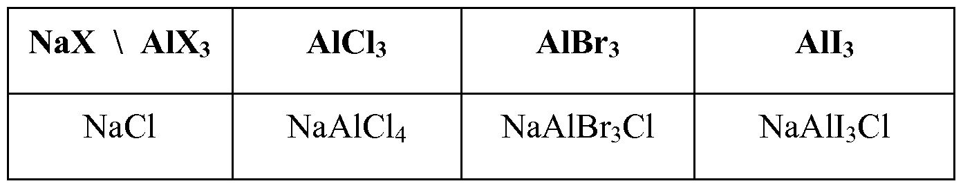
[0070] The following Table 1 illustrates some non- limiting combinations of NaX and
AlX3 to form NaAlX4.
[0071] Table 1
Figure imgf000012_0002
NaBr NaAlCl3Br NaAlBr4 NaAlI3Br
Nal NaAlCl3I NaAlBr3I NaAlI4
[0072] In other embodiments, the positive electrode is disposed in a mixed molten salt positive electrolyte comprising at least three salts that can be represented by the formula NaAlX'4_5_roX"5X"'ro, where X', X" and X' " are three different halogens selected from CI, Br, and I, where 0 < δ < 4, 0 < in < 4, and 0 < δ + τπ < 4. The mixed molten salt positive electrolyte comprises NaAlCl4, NaAlBr4, and NaAlI4, at various molar ratios.
[0073] In some embodiments, the positive electrolyte 35 also comprises one or more halogens and/or halides. In this regard, the halogens and halides, as well polyhalides and/or metal halides that form therefrom (e.g. , where the current collector 30 comprises a metal, such as copper, nickel, zinc, etc. (as discussed below)) can perform any suitable function, including, without limitation, acting as the positive electrode as the cell 10 operates. Some examples of suitable halogens include bromine, iodine, and chlorine. Similarly, some examples of suitable halides include bromide ions, polybromide ions, iodide ions, polyiodide ions, chloride ions, and polychloride ions. While the halogens/halides can be introduced into the positive electrode solution in any suitable manner, in some embodiments, they are added as NaX, wherein X is selected from Br, I, CI, etc.
[0074] With reference now to the terminals 45 and 50, the cell 10 can comprise any suitable terminals that are capable of electrically connecting the cell with an external circuit (not shown), including without limitation, to one or more cells. In this regard, the terminals can comprise any suitable material, be of any suitable shape, and be of any suitable size.
[0075] In addition to the aforementioned components, the cell 10 can optionally comprise any other suitable component. By way of non-limiting illustration Figures 1 and 2 show an embodiment in which the cell 10 comprises a heat management system 55, 60. Independent heat management systems may be associated with the negative electrode and positive electrode compartments. Alternatively, a single heat management system may be disposed in only one compartment or to the exterior of the cell 10 generally. In such embodiments, the cell can comprise any suitable type of heat management system that is capable of maintaining the cell within a suitable operating temperature range. Some examples of such heat management systems include, but are not limited to, a heater, a cooler, one or more temperature sensors, and appropriate temperature control circuitry. [0076] The described cell 10 may function at any suitable operating temperature. In other words, as the cell is discharged and/or recharged, the sodium negative electrode and the positive electrolyte may have any suitable temperature. The negative and positive electrode compartments may operate at the same or different temperatures. Indeed, in some embodiments, the cell functions at an intermediate operating temperature in the range from about 80 °C to about 210 °C. In other embodiments, the cell may function at an intermediate operating temperature in the range from about 1 10 °C to about 180 °C. In yet another embodiment, the operating temperature of the cell in the range of about 150 °C to about 170 °C.
[0077] The following examples are given to illustrate various embodiments within, and aspects of, the scope of the present invention. These are given by way of example only, and it is understood that the following examples are not comprehensive or exhaustive of the many types of embodiments of the present invention that can be prepared in accordance with the present invention.
[0078] Example 1
[0079] The conductivity of Nal in a molten salt positive electrolyte AICI3 was compared to the conductivity of Nal in an organic solvent solution that included N-methyl formamide. The molten salt positive electrolyte had a general formula of NaAlxIyClz. The conductivity of Nal in a molten salt positive electrolyte was approximately three times the conductivity of the organic solvent-based electrolyte at 120 °C, as shown in Fig. 4. Cells utilizing a molten salt positive electrolyte will be more energy dense due to higher molarity of Nal. Furthermore, cells utilizing a molten salt positive electrolyte are safer than organic solvent based positive electrolyte solutions because if molten sodium happens to contact the molten salt positive electrolyte, the chemical reaction would only produce non-flammable salts.
[0080] Example 2
[0081] A sodium-iodine secondary cell was prepared as described herein containing sodium iodide in molten AICI3 in a 60:40 NaI:AlCl3 ratio (a "basic" electrolyte). Tungsten wire was used as the positive current collector. NaSICON was used to separate a molten sodium negative electrode from the positive electrode/positive electrolyte. The oxidation of iodide was measured and found to produce two oxidation peaks, consistent with Battery Chemistry 1 and Battery Chemistry 2, described herein. Experimental results are shown in Fig. 5A. The oxidation peaks were found to be reversible. Additional tests were performed using an "acidic" electrolyte comprising sodium iodide in molten AICI3 in a 40:60 NaI:AlCl3 ratio. Experimental results are shown in Fig. 5B. The results suggest that the second oxidation peak in the basic electrolyte occurs at a similar potential as the first iodide oxidation peak in the acidic electrolyte. The reduction peak in acidic electrolyte occurs at a higher potential. This suggests that whether the electrolyte is acidic or basic affects the potential of I2 generation.
[0082] Example 3
[0083] Three symmetrical sodium-iodine secondary cells were prepared to test the reversibility of the oxidation / reduction reactions that occur in the positive electrode / positive electrolyte. The symmetrical cells were prepared as set forth in Table 2, below:
[0084] Table 2
Figure imgf000015_0001
[0085] The symmetrical cells were operated as set forth in Table 3, below: [0086] Table 3
Figure imgf000015_0002
[0087] A graph of the current vs. voltage for the operation of the symmetrical cells is shown in Fig. 6. Because there is little or no hysteresis shown in Fig. 6, it may be concluded that the oxidation / reduction reactions that occur in the positive electrode / positive electrolyte are highly reversible.
[0088] Embodiments of the present invention may be embodied in other specific forms without departing from its spirit or essential characteristics. The described embodiments and examples are to be considered in all respects only as illustrative and not as restrictive. The scope of the invention is, therefore, indicated by the appended claims rather than by the foregoing description. All changes that come within the meaning and range of equivalency of the claims are to be embraced within their scope.
[0089] What is claimed is:

Claims

CLAIMS:
1. A sodium-halogen secondary cell, comprising:
a negative electrode compartment comprising a negative electrode that comprises metallic sodium in molten or solid state, wherein the negative electrode electrochemically oxidizes to release sodium ions during discharge and electrochemically reduces sodium ions to form sodium metal during recharge;
a positive electrode comprising NaX disposed in a molten positive electrolyte comprising one or more AIX3 salts, wherein X may be the same or different halogen selected from CI, Br, and I, wherein the ratio of NaX to AIX3 is greater than or equal to one; and
a sodium ion conductive solid electrolyte membrane that separates the negative electrode from the liquid positive electrode solution.
2. The secondary cell of claim 1, wherein the molten positive electrolyte comprises two different AIX3 salts and is represented by the general formula
Figure imgf000017_0001
where 0 < δ < 4, wherein X' and X" are different halogens selected from CI, Br and I.
3. The secondary cell of claim 2, wherein the positive electrode and the molten positive electrolyte are in the form of a mixed molten salt comprising at least two salts of the general formula NaAlX'4 and NaAlX"4 at various molar ratios.
4. The secondary cell of claim 3, wherein the molar ratio of NaAlX'4 to NaAlX"4 is in the range of 9: 1 to 1 :9 with corresponding δ values of 0.4 to 3.6.
5. The secondary cell of claim 3, wherein the positive electrode comprises additional NaX or a mixture of NaX compounds added in a molar ratio to the mixed molten salt positive electrolyte ranging from 1 : 1 to 3: 1 of NaX : NaAlX gX'
6. The secondary cell of claim 1, wherein the secondary cell operates at a temperature between about 80 °C and 210° C.
7. The secondary cell of claim 1, wherein the electrolyte membrane comprises a NaSICON-type material.
8. The secondary cell of claim 1 , wherein molten salt positive electrolyte comprises three different A1X3 salts and is represented by the general formula NaAlX'4_
Figure imgf000018_0001
where X', X" and X' " are three different halogens selected from CI, Br, and I, where 0 < δ < 4, 0 < in < 4, and 0 < δ + in < 4.
9. The secondary cell of claim 8, wherein the positive electrode and the molten positive electrolyte are in the form of a mixed molten salt comprising at least three salts of the formula NaAlCl4, NaAlBr4, and NaAlI4, at various molar ratios.
10. The secondary cell of claim 8, wherein the positive electrode comprises additional NaX or a mixture of NaX compounds added in a molar ratio to the mixed molten salt positive electrolyte ranging from 1 : 1 to 3 : 1 of NaX : NaAlX'4_5_raX"5X'"ra, where 0 < δ < 4, 0 < τπ < 4, and 0 < δ + τπ < 4.
1 1. The secondary cell of claim 10, wherein the additional NaX is present as a solid phase within the current collector.
12. The secondary cell of claim 1, wherein the positive electrode comprises a current collector comprising at least one of carbon, tungsten, molybdenum, and titanium.
13. The secondary cell of claim 1 1 , wherein the current collector comprises at least one of wires, felts, foils, plates, parallel plates, tubes, meshes, mesh screens, and foams.
14. A sodium-halogen secondary cell, comprising:
a negative electrode compartment comprising a negative electrode that comprises metallic sodium in molten state, wherein the negative electrode electrochemically oxidizes to release sodium ions during discharge and electrochemically reduces sodium ions to form sodium metal during recharge;
a positive electrode comprising Nal disposed in a molten positive electrolyte comprising one or more AIX3 salts, wherein X may be the same or different halogen selected from CI, Br, and I, wherein the ratio of Nal to AIX3 is greater than one; and
a sodium ion conductive solid electrolyte membrane that separates the negative electrode from the liquid positive electrode solution.
PCT/US2015/063244 2014-12-04 2015-12-01 Sodium-halogen secondary cell WO2016089902A1 (en)

Priority Applications (3)

Application Number Priority Date Filing Date Title
EP15865518.3A EP3227951B1 (en) 2014-12-04 2015-12-01 Sodium-halogen secondary cell
KR1020177017918A KR20170092619A (en) 2014-12-04 2015-12-01 Sodium-halogen secondary cell
JP2017529996A JP6659691B2 (en) 2014-12-04 2015-12-01 Sodium-halogen secondary battery

Applications Claiming Priority (2)

Application Number Priority Date Filing Date Title
US201462087507P 2014-12-04 2014-12-04
US62/087,507 2014-12-04

Publications (1)

Publication Number Publication Date
WO2016089902A1 true WO2016089902A1 (en) 2016-06-09

Family

ID=56092343

Family Applications (1)

Application Number Title Priority Date Filing Date
PCT/US2015/063244 WO2016089902A1 (en) 2014-12-04 2015-12-01 Sodium-halogen secondary cell

Country Status (4)

Country Link
EP (1) EP3227951B1 (en)
JP (1) JP6659691B2 (en)
KR (1) KR20170092619A (en)
WO (1) WO2016089902A1 (en)

Cited By (1)

* Cited by examiner, † Cited by third party
Publication number Priority date Publication date Assignee Title
EP3357123A4 (en) * 2015-10-01 2019-05-15 Dynantis Corp. Sodium metal batteries with intercalating cathode

Citations (5)

* Cited by examiner, † Cited by third party
Publication number Priority date Publication date Assignee Title
US20110104526A1 (en) * 2009-11-05 2011-05-05 Chett Boxley Solid-state sodium-based secondary cell having a sodium ion conductive ceramic separator
US20120015256A1 (en) * 2009-03-27 2012-01-19 Tokyo University Of Science Educational Foundation Administrative Organization Sodium ion secondary battery
US20130052525A1 (en) * 2011-08-24 2013-02-28 Sumitomo Chemical Company, Limited Sodium secondary battery
US20130196224A1 (en) * 2012-02-01 2013-08-01 Battelle Memorial Institute Intermediate Temperature Sodium Metal-Halide Energy Storage Devices
WO2013154349A1 (en) * 2012-04-10 2013-10-17 Sk Innovation Co.,Ltd. Sodium secondary battery

Family Cites Families (6)

* Cited by examiner, † Cited by third party
Publication number Priority date Publication date Assignee Title
US3632448A (en) * 1968-07-29 1972-01-04 Exxon Research Engineering Co Aluminum-halogen secondary battery method with molten electrolyte
FR2115522A5 (en) * 1970-11-23 1972-07-07 Accumulateurs Fixes Sodium-sodium halide cell - using aluminium chloride-sodium halide complexes
US3877984A (en) * 1974-04-24 1975-04-15 Esb Inc Alkali metal-metal chloride battery
ZA828603B (en) * 1981-12-10 1983-09-28 South African Inventions Electrochemical cell
US10224577B2 (en) * 2011-11-07 2019-03-05 Field Upgrading Usa, Inc. Battery charge transfer mechanisms
KR102114716B1 (en) * 2012-09-06 2020-05-26 필드 업그레이딩 유에스에이, 인코포레이티드 Sodium-halogen secondary cell

Patent Citations (5)

* Cited by examiner, † Cited by third party
Publication number Priority date Publication date Assignee Title
US20120015256A1 (en) * 2009-03-27 2012-01-19 Tokyo University Of Science Educational Foundation Administrative Organization Sodium ion secondary battery
US20110104526A1 (en) * 2009-11-05 2011-05-05 Chett Boxley Solid-state sodium-based secondary cell having a sodium ion conductive ceramic separator
US20130052525A1 (en) * 2011-08-24 2013-02-28 Sumitomo Chemical Company, Limited Sodium secondary battery
US20130196224A1 (en) * 2012-02-01 2013-08-01 Battelle Memorial Institute Intermediate Temperature Sodium Metal-Halide Energy Storage Devices
WO2013154349A1 (en) * 2012-04-10 2013-10-17 Sk Innovation Co.,Ltd. Sodium secondary battery

Cited By (2)

* Cited by examiner, † Cited by third party
Publication number Priority date Publication date Assignee Title
EP3357123A4 (en) * 2015-10-01 2019-05-15 Dynantis Corp. Sodium metal batteries with intercalating cathode
US10601062B2 (en) 2015-10-01 2020-03-24 Dynantis Corp. Sodium metal batteries with intercalating cathode

Also Published As

Publication number Publication date
EP3227951A1 (en) 2017-10-11
EP3227951A4 (en) 2018-08-01
EP3227951B1 (en) 2019-08-28
KR20170092619A (en) 2017-08-11
JP2017536683A (en) 2017-12-07
JP6659691B2 (en) 2020-03-04

Similar Documents

Publication Publication Date Title
CA2983001C (en) Sodium-aluminum battery with sodium ion conductive ceramic separator
EP2893590B1 (en) Sodium-halogen secondary cell
US9537179B2 (en) Intermediate temperature sodium-metal halide battery
CA2902908C (en) Low temperature battery with molten sodium-fsa electrolyte
US20130244085A1 (en) Battery with non-porous alkali metal ion conductive honeycomb structure separator
JP2015515723A (en) Batteries having non-polar alkali metal ion conducting honeycomb structure separator
US10854929B2 (en) Sodium-halogen secondary cell
EP2973838B1 (en) Low temperature secondary cell with sodium intercalation electrode
DK3050153T3 (en) MIDDLE-TEMPERATURE SODIUM METAL HALOGENIDE BATTERY
WO2015035427A1 (en) Sodium-halogen secondary cell
EP3227951B1 (en) Sodium-halogen secondary cell
US20150030896A1 (en) Sodium-halogen secondary cell

Legal Events

Date Code Title Description
121 Ep: the epo has been informed by wipo that ep was designated in this application

Ref document number: 15865518

Country of ref document: EP

Kind code of ref document: A1

ENP Entry into the national phase

Ref document number: 2017529996

Country of ref document: JP

Kind code of ref document: A

NENP Non-entry into the national phase

Ref country code: DE

ENP Entry into the national phase

Ref document number: 20177017918

Country of ref document: KR

Kind code of ref document: A

REEP Request for entry into the european phase

Ref document number: 2015865518

Country of ref document: EP