EP3227951B1 - Sodium-halogen secondary cell - Google Patents
Sodium-halogen secondary cell Download PDFInfo
- Publication number
- EP3227951B1 EP3227951B1 EP15865518.3A EP15865518A EP3227951B1 EP 3227951 B1 EP3227951 B1 EP 3227951B1 EP 15865518 A EP15865518 A EP 15865518A EP 3227951 B1 EP3227951 B1 EP 3227951B1
- Authority
- EP
- European Patent Office
- Prior art keywords
- sodium
- positive electrode
- secondary cell
- positive
- electrolyte
- Prior art date
- Legal status (The legal status is an assumption and is not a legal conclusion. Google has not performed a legal analysis and makes no representation as to the accuracy of the status listed.)
- Active
Links
Images

Classifications
-
- H—ELECTRICITY
- H01—ELECTRIC ELEMENTS
- H01M—PROCESSES OR MEANS, e.g. BATTERIES, FOR THE DIRECT CONVERSION OF CHEMICAL ENERGY INTO ELECTRICAL ENERGY
- H01M10/00—Secondary cells; Manufacture thereof
- H01M10/36—Accumulators not provided for in groups H01M10/05-H01M10/34
- H01M10/39—Accumulators not provided for in groups H01M10/05-H01M10/34 working at high temperature
- H01M10/399—Cells with molten salts
-
- H—ELECTRICITY
- H01—ELECTRIC ELEMENTS
- H01M—PROCESSES OR MEANS, e.g. BATTERIES, FOR THE DIRECT CONVERSION OF CHEMICAL ENERGY INTO ELECTRICAL ENERGY
- H01M10/00—Secondary cells; Manufacture thereof
- H01M10/05—Accumulators with non-aqueous electrolyte
- H01M10/056—Accumulators with non-aqueous electrolyte characterised by the materials used as electrolytes, e.g. mixed inorganic/organic electrolytes
- H01M10/0561—Accumulators with non-aqueous electrolyte characterised by the materials used as electrolytes, e.g. mixed inorganic/organic electrolytes the electrolyte being constituted of inorganic materials only
- H01M10/0562—Solid materials
-
- H—ELECTRICITY
- H01—ELECTRIC ELEMENTS
- H01M—PROCESSES OR MEANS, e.g. BATTERIES, FOR THE DIRECT CONVERSION OF CHEMICAL ENERGY INTO ELECTRICAL ENERGY
- H01M4/00—Electrodes
- H01M4/02—Electrodes composed of, or comprising, active material
- H01M4/36—Selection of substances as active materials, active masses, active liquids
- H01M4/38—Selection of substances as active materials, active masses, active liquids of elements or alloys
- H01M4/381—Alkaline or alkaline earth metals elements
-
- H—ELECTRICITY
- H01—ELECTRIC ELEMENTS
- H01M—PROCESSES OR MEANS, e.g. BATTERIES, FOR THE DIRECT CONVERSION OF CHEMICAL ENERGY INTO ELECTRICAL ENERGY
- H01M4/00—Electrodes
- H01M4/02—Electrodes composed of, or comprising, active material
- H01M4/36—Selection of substances as active materials, active masses, active liquids
- H01M4/58—Selection of substances as active materials, active masses, active liquids of inorganic compounds other than oxides or hydroxides, e.g. sulfides, selenides, tellurides, halogenides or LiCoFy; of polyanionic structures, e.g. phosphates, silicates or borates
- H01M4/582—Halogenides
-
- H—ELECTRICITY
- H01—ELECTRIC ELEMENTS
- H01M—PROCESSES OR MEANS, e.g. BATTERIES, FOR THE DIRECT CONVERSION OF CHEMICAL ENERGY INTO ELECTRICAL ENERGY
- H01M4/00—Electrodes
- H01M4/02—Electrodes composed of, or comprising, active material
- H01M4/64—Carriers or collectors
- H01M4/66—Selection of materials
- H01M4/661—Metal or alloys, e.g. alloy coatings
- H01M4/662—Alloys
-
- H—ELECTRICITY
- H01—ELECTRIC ELEMENTS
- H01M—PROCESSES OR MEANS, e.g. BATTERIES, FOR THE DIRECT CONVERSION OF CHEMICAL ENERGY INTO ELECTRICAL ENERGY
- H01M4/00—Electrodes
- H01M4/02—Electrodes composed of, or comprising, active material
- H01M4/64—Carriers or collectors
- H01M4/66—Selection of materials
- H01M4/663—Selection of materials containing carbon or carbonaceous materials as conductive part, e.g. graphite, carbon fibres
-
- H—ELECTRICITY
- H01—ELECTRIC ELEMENTS
- H01M—PROCESSES OR MEANS, e.g. BATTERIES, FOR THE DIRECT CONVERSION OF CHEMICAL ENERGY INTO ELECTRICAL ENERGY
- H01M4/00—Electrodes
- H01M4/02—Electrodes composed of, or comprising, active material
- H01M4/64—Carriers or collectors
- H01M4/70—Carriers or collectors characterised by shape or form
- H01M4/72—Grids
- H01M4/74—Meshes or woven material; Expanded metal
-
- H—ELECTRICITY
- H01—ELECTRIC ELEMENTS
- H01M—PROCESSES OR MEANS, e.g. BATTERIES, FOR THE DIRECT CONVERSION OF CHEMICAL ENERGY INTO ELECTRICAL ENERGY
- H01M4/00—Electrodes
- H01M4/02—Electrodes composed of, or comprising, active material
- H01M4/64—Carriers or collectors
- H01M4/70—Carriers or collectors characterised by shape or form
- H01M4/80—Porous plates, e.g. sintered carriers
- H01M4/808—Foamed, spongy materials
-
- H—ELECTRICITY
- H01—ELECTRIC ELEMENTS
- H01M—PROCESSES OR MEANS, e.g. BATTERIES, FOR THE DIRECT CONVERSION OF CHEMICAL ENERGY INTO ELECTRICAL ENERGY
- H01M2300/00—Electrolytes
- H01M2300/0017—Non-aqueous electrolytes
- H01M2300/0048—Molten electrolytes used at high temperature
- H01M2300/0054—Halogenides
- H01M2300/0057—Chlorides
-
- H—ELECTRICITY
- H01—ELECTRIC ELEMENTS
- H01M—PROCESSES OR MEANS, e.g. BATTERIES, FOR THE DIRECT CONVERSION OF CHEMICAL ENERGY INTO ELECTRICAL ENERGY
- H01M2300/00—Electrolytes
- H01M2300/0017—Non-aqueous electrolytes
- H01M2300/0065—Solid electrolytes
- H01M2300/0068—Solid electrolytes inorganic
-
- Y—GENERAL TAGGING OF NEW TECHNOLOGICAL DEVELOPMENTS; GENERAL TAGGING OF CROSS-SECTIONAL TECHNOLOGIES SPANNING OVER SEVERAL SECTIONS OF THE IPC; TECHNICAL SUBJECTS COVERED BY FORMER USPC CROSS-REFERENCE ART COLLECTIONS [XRACs] AND DIGESTS
- Y02—TECHNOLOGIES OR APPLICATIONS FOR MITIGATION OR ADAPTATION AGAINST CLIMATE CHANGE
- Y02E—REDUCTION OF GREENHOUSE GAS [GHG] EMISSIONS, RELATED TO ENERGY GENERATION, TRANSMISSION OR DISTRIBUTION
- Y02E60/00—Enabling technologies; Technologies with a potential or indirect contribution to GHG emissions mitigation
- Y02E60/10—Energy storage using batteries
Definitions
- the disclosed invention relates to an intermediate temperature, sodium - halogen secondary cell (or rechargeable battery) with a sodium ion conductive electrolyte membrane and a positive electrolyte that comprises one or more sodium haloaluminate salts and a sodium halide.
- the battery system utilizes a molten eutectic mixture of sodium haloaluminate salts having a relatively low melting point.
- Batteries are known devices that are used to store and release electrical energy for a variety of uses. In order to produce electrical energy, batteries typically convert chemical energy directly into electrical energy. Generally, a single battery includes one or more galvanic cells, wherein each of the cells is made of two half-cells that arc electrically isolated except through an external circuit. During discharge, electrochemical reduction occurs at the cell's positive electrode, while electrochemical oxidation occurs at the cell's negative electrode. While the positive electrode and the negative electrode in the cell do not physically touch each other, they arc generally chemically connected by at least one (or more) ionically conductive and electrically insulative electrolytes, which can either be in a solid state, a liquid state, or in a combination of such states. When an external circuit, or a load, is connected to a terminal that is connected to the negative electrode and to a terminal that is connected to the positive electrode, the battery drives electrons through the external circuit, while ions migrate through the electrolyte.
- Batteries can be classified in a variety of manners. For example, batteries that are completely discharged only once arc often referred to as primary batteries or primary cells. In contrast, batteries that can be discharged and recharged more than once are often referred to as secondary batteries or secondary cells. The ability of a cell or battery to be charged and discharged multiple times depends on the Faradaic efficiency of each charge and discharge cycle.
- While rechargeable batteries based on sodium can comprise a variety of materials and designs, most, if not all, sodium batteries that require a high Faradaic efficiency employ a solid primary electrolyte separator, such as a solid ceramic primary electrolyte membrane.
- a solid primary electrolyte separator such as a solid ceramic primary electrolyte membrane.
- the principal advantage of using a solid ceramic primary electrolyte membrane is that the Faradaic efficiency of the resulting cell approaches 100%. Indeed, in almost all other cell designs, electrode solutions in the cell are able to intermix over time and, thereby, cause a drop in Faradaic cfficicncy and loss of battery capacity.
- the primary electrolyte separators used in sodium batteries that require a high Faradaic efficiency often consist of ionically conductive polymers, porous materials infiltrated with ionically conductive liquids or gels, or dense ceramics.
- many rechargeable sodium batteries that are presently available for commercial applications comprise a molten sodium metal negative electrode, a sodium ⁇ "-alumina ceramic electrolyte separator, and a molten positive electrode, which may include a composite of molten sulfur and carbon (called a sodium/sulfur cell).
- sodium-based rechargeable batteries may have significant shortcomings.
- the sodium ⁇ "-alumina ceramic electrolyte separator is typically more conductive and is better wetted by molten sodium at a temperature in excess of about 270° C and/or because the molten positive electrode typically requires relatively high temperatures (e.g., temperatures above about 170° or 180° C) to remain molten
- many conventional sodium-based rechargeable batteries operate at temperatures higher than about 270° C and arc subject to significant thermal management problems and thermal sealing issues.
- some sodium-based rechargeable batteries may have difficulty dissipating heat from the batteries or maintaining the negative electrode and the positive electrode at the relatively high operating temperatures.
- the relatively high operating temperatures of some sodium-based batteries can create significant safety issues.
- the relatively high operating temperatures of some sodium-based batteries require their components to be resistant to, and operable at, such high temperatures. Accordingly, such components can be relatively expensive.
- such batteries can be expensive to operate and energy inefficient.
- FR 2115522 discloses a non-aqueous rechargeable cell operating at 110-200, preferably 150, degrees C, wherein the cell comprises (Na/beta Al 2 O 3 (Na)/NaI(Br, Cl).AlCl 3 ) discharged or (Na/beta Al 2 O 3 (Na)/I 2 (Br 2 , Cl 2 ) plus NaCl(Br).AlCl 3 ) when charged.
- Iodine is the preferred halogen and the AlCl 3 forms low melting complexes and suppresses the formation of polyhalides such as NaI 3 .
- the mixed halides are contained in carbon felt.
- the operating temperature is lower than sodium/sulphur cells (300 degrees C).
- the active material for the positive compartment is prepared by mixing the solid halides, melting, homogenising, freezing and grinding.
- US 4546055 discloses an electrochemical cell that is provided with a molten sodium anode and a molten sodium aluminium halide salt electrolyte.
- the cathode comprises FeCl 2 , NiCl 2 , CoCl 2 or CrCl 2 as active cathode substance dispersed in an electronically conductive electrolyte-permeable matrix which is impregnated by the electrolyte.
- a solid conductor of sodium ions or a micromolecular sieve which contains sodium sorbed therein.
- the proportions of sodium and aluminium ions in the electrolyte are selected so that the solubility of the active cathode substance in the electrolyte is at or near its minimum.
- US 2014/030571 discloses a secondary cell having a negative electrode compartment and a positive electrode compartment, which are separated by an alkali ion conductive electrolyte membrane.
- An alkali metal negative electrode disposed in the negative electrode compartment oxidizes to release alkali ions as the cell discharges and reduces the alkali ions to alkali metal during recharge.
- the positive electrode compartment includes a positive electrode contacting a positive electrode solution that includes an alkali metal compound and a metal halide.
- the alkali metal compound can be selected from an alkali halide and an alkali pseudo-halide.
- the metal ion reduces to form metal plating on the positive electrode.
- the metal plating oxidizes to strip the metal plating to form metal halide or pseudo halide or corresponding metal complex.
- US 3877984 discloses a secondary battery utilizing a molten alkali metal negative reactant, a metal chloride positive reactant, a molten alkali metal chloraluminate electrolyte and a selectively-ionically-conductive separator positioned between the negative and the positive reactants.
- the present invention provides a sodium-halogen secondary cell, comprising:
- the disclosed secondary cells include a positive electrode compartment housing a current collector disposed in a liquid positive electrode solution.
- suitable positive electrode solution materials include organic solvents such as dimethyl sulfoxide, NMF (N-methylformamide), and ionic liquids.
- the present disclosure provides an improvement to the positive electrode solution of the sodium-halogen secondary cells disclosed in Applicant's copending application.
- the battery system utilizes a molten eutectic mixture of sodium haloaluminate salts having a relatively low melting point.
- a sodium ion conductive solid electrolyte separates the negative electrode and the liquid positive electrode solution.
- the sodium ion conductive solid electrolyte comprises a NaSICON electrolyte material.
- the NaSICON electrolyte material has high sodium conductivity at cell operating temperatures.
- the battery operates at a temperature in the range from 80 °C to 210 °C.
- the rechargeable sodium-halogen battery includes a negative electrode comprising metallic sodium in molten or solid state.
- the positive electrode comprises NaX, where X is a halogen selected from Cl, Br and I.
- the positive electrode is disposed in a molten salt positive electrolyte comprising a mixture of at least two AlX 3 salts that can be represented by the formula NaAlX' 4- ⁇ , where 0 ⁇ ⁇ ⁇ 4, wherein X' and X" are different halogens selected from Cl, Br and I.
- the mixed molten salt positive electrolyte comprises at least two salts of the general formula NaAlX' 4 and NaAlX" 4 at various molar ratios, wherein X' and X" are different halogens selected from Cl, Br and I.
- the molar ratio of NaAlX' 4 to NaAlX" 4 is in the range of 9:1 to 1:9 with corresponding ⁇ values of 0.4 to 3.6.
- the positive electrode comprises NaX or a mixture of NaX compounds added in a molar ratio to the mixed molten salt positive electrolyte ranging from 1:1 to 3:1 of NaX : NaAlX' 4- ⁇ X" ⁇ .
- the excess NaX renders the positive electrolyte highly basic.
- the positive electrode and mixed molten salt positive electrolyte is a molten liquid or a two phase mixture wherein the mixed molten salt positive electrolyte is predominantly a liquid phase and the NaX or mixture of NaX compounds is a solid phase.
- the positive electrode is disposed in a mixed molten salt positive electrolyte comprising at least three salts that can be represented by the formula where X', X" and X''' are three different halogens selected from Cl, Br, and I, where 0 ⁇ 6 ⁇ 4, 0 ⁇ ⁇ ⁇ 4 , and 0 ⁇ ⁇ + ⁇ ⁇ 4 .
- the mixed molten salt positive electrolyte comprises NaAlCl 4 , NaAlBr 4 , and NaAlI 4 , at various molar ratios.
- the embodiments according to the Invention provide a sodium-halogen secondary cell, which includes a molten or solid state sodium negative electrode and a sodium halide positive electrode disposed in a molten positive electrolyte that comprises one or more haloaluminatc salts.
- the secondary cell utilizes as the positive electrolyte a molten eutectic mixture of sodium haloaluminate salts having a relatively low melting point.
- Figure 1 shows a representative embodiment in which the sodium secondary cell 10 comprises a negative electrode compartment 15 that includes a sodium metal negative electrode 20 and a positive electrode compartment 25 that comprises a sodium halide positive electrode.
- the positive electrode includes a current collector 30 disposed in a positive electrolyte 35 comprising one or more molten haloaluminate salts (AlCl 3 , AlBr 3 , and AlI 3 )
- a sodium ion conductive electrolyte membrane 40 separates the negative electrode from the liquid positive electrode solution and positive electrolyte 35.
- the sodium ion conductive electrolyte membrane 40 separates a first terminal 45 from a second terminal 50.
- Figure 1 illustrates that as the cell 10 is discharged and electrons (c - ) flow from the negative electrode 20 ( e.g., via the first terminal 45), sodium is oxidized from the negative electrode 20 to form sodium ions (Na + ).
- Figure 1 shows that these sodium ions arc respectively transported from the sodium negative electrode 20, through the sodium ion conductive membrane 40, and to the positive electrolyte 35.
- Figure 2 shows that as the secondary cell 10 is recharged and electrons (c - ) flow into the sodium negative electrode 20 from an external power source (not shown), such as a recharger, the chemical reactions that occurred when the cell 10 was discharged (as shown in Figure 1 ) are reversed.
- Figure 2 shows that as the cell 10 is recharged, sodium ions (Na) arc respectively transported from the positive electrolyte 35, through the electrolyte membrane 40, and to the negative electrode 20, where the sodium ions are reduced to form sodium metal (Na).
- the cell as mentioned above comprises a negative electrode compartment 15 and a positive electrode compartment 25.
- the two compartments can be any suitable shape and have any other suitable characteristic that allows the cell 10 to function as intended.
- the negative electrode and the positive electrode compartments can be tubular, rectangular, or be any other suitable shape.
- the two compartments can have any suitable spatial relationship with respect to each other.
- FIG. 2 shows that the negative electrode compartment 15 and the positive electrode compartment 25 can be adjacent to each other, in other embodiments (not shown), one compartment (e.g., the negative electrode compartment) is disposed, at least partially, in the other compartment (e.g., the positive electrode compartment), while the contents of the two compartments remain separated by the electrolyte membrane 40 and any other compartmental walls.
- one compartment e.g., the negative electrode compartment
- the other compartment e.g., the positive electrode compartment
- the cell 10 can comprise any suitable sodium negative electrode 20 that allows the cell 10 to function (e.g., be discharged and recharged) as intended.
- suitable sodium negative electrode materials include, but arc not limited to, a sodium sample that is substantially pure and a sodium alloy comprising any other suitable sodium-containing negative electrode material.
- the negative electrode comprises or consists of an amount of sodium that is substantially pure. In such embodiments, because the melting point of pure sodium is around 98° C, the sodium negative electrode will become molten above that temperature.
- the positive electrode compartment 25 can comprise any suitable positive electrode that allows the cell to be charged and discharged as intended.
- the positive electrode can comprise virtually any current collector 30 in combination with a halogen, shown generically as "X" in Figs. 1 and 2 , in a positive electrolyte 35 comprising at least two sodium haloaluminate salts.
- the current collector 30 can be disposed in any suitable location in the positive electrode compartment 25 that allows the cell 10 to function as intended.
- the cell 10 can comprise any suitable current collector that allows the cell to be charged and discharged as intended.
- the current collector can comprise virtually any current collector configuration that has been successfully used in a sodium-based rechargeable battery system.
- the current collector comprises at least one of wires, felts, foils, plates, parallel plates, tubes, meshes, mesh screens, foams, and/or other suitable current collector configuration.
- the foam may include, without limitation, metal foams and carbon foams.
- the current collector comprises a configuration having a relatively large surface area which may include one or more mesh screens and metal foams.
- the current collector 30 can comprise any suitable material that allows the cell 10 to function as intended.
- suitable current collector materials include tungsten, stainless steel, carbon, molybdenum, titanium, platinum, copper, nickel, zinc, a sodium intercalation material (e.g., Na X MnO 2 , etc.), nickel foam, nickel, a sulfur composite, a sulfur halide (e.g., sulfuric chloride), and/or another suitable material.
- these materials may coexist or exist in combinations.
- the current collector comprises tungsten, carbon, molybdenum, titanium.
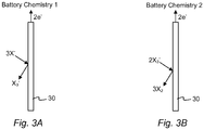
- the reactions that may occur at the negative electrode 20, the positive electrode/current collector 30, and the overall reaction as the cell 10 is discharged may occur in at least two steps. These two potential reactions arc shown below and designated Battery Chemistry 1 (shown schematically in Fig. 3A for battery recharge) and Battery Chemistry 2 (shown schematically in Fig. 3B for battery recharge). It has been observed that these reactions may be individual steps of a multi-step reaction, or depending upon the battery conditions, one step may be favored over another step.
- X comprises iodine, bromine, or chlorine.
- the cell 10 may have the following chemical reactions and the following theoretical voltage (V vs. SHE (standard hydrogen electrode)) and theoretical specific energy (Wh/kg):
- the charging reactions at the positive electrode may occur in two steps: 1) iodide to triiodide and 2) triiodide to iodine.
- discharging reactions at the positive electrode may occur in two steps: 1) iodine to triiodide and 2) triiodide to iodide.
- the charging and discharging reactions may occur using the combination of reaction chemistries above.
- the cell 10 may have the following chemical reactions and the following theoretical voltage (V vs. SHE) and theoretical specific energy (Wh/kg):
- the charging reactions at the positive electrode may occur in two steps: 1) bromide to tribromide and 2) tribromide to bromine.
- discharging reactions at the positive electrode may occur in two steps: 1) bromine to tribromide and 2) tribromide to bromide.
- the charging and discharging reactions may occur using the combination of reaction chemistries above.
- an alternative positive electrode chemistry may include:
- the membrane can comprise any suitable material that selectively transports sodium ions and permits the cell 10 to function with a positive electrolyte 35.
- the electrolyte membrane comprises a NaSICON-type (sodium Super Ion CONductive) material.
- the NaSICON-type material may comprise any known or novel NaSICON-type material that is suitable for use with the described cell 10.
- the NaSICON-type membrane comprises Na 3 Si 2 Zr 2 PO 12
- the NaSICON-type membrane comprises one or more NaSELECT x materials, produced by Ccramatcc, Inc. in Salt Lake City, Utah.
- the positive electrode comprises NaX, where X is a halogen selected from Cl, Br and I.
- the positive electrode is preferably NaI.
- the positive electrode is disposed in a molten salt positive electrolyte comprising AlX 3 , NaX and AlX 3 combine to form NaAlX 4 as follows: NaX + AlX 3 ⁇ NaAlX 4
- the positive electrode is combined with a mixture of at least two AlX 3 salts.
- the combination of positive electrode and positive electrolyte can be represented by the general formula NaAlX' 4- ⁇ X" ⁇ , where 0 ⁇ ⁇ ⁇ 4, wherein X' and X" are different halogens selected from Cl, Br and I.
- the mixed molten salt positive electrolyte comprises at least two salts of the general formula NaAlX' 4 and NaAlX" 4 at various molar ratios, wherein X' and X" arc different halogens selected from Cl, Br and I.
- the molar ratio of NaAlX' 4 to NaAlX" 4 is in the range of 9:1 to 1:9 with corresponding ⁇ values of 0.4 to 3.6.
- the positive electrode comprises NaX or a mixture of NaX compounds added in a molar ratio to the mixed molten salt positive electrolyte ranging from 1:1 to 3:1 of NaX : NaAlX' 4- ⁇ X" ⁇ .
- the excess NaX renders the positive electrolyte highly basic.
- the positive electrode and mixed molten salt positive electrolyte is a molten liquid or a two phase mixture wherein the mixed molten salt positive electrolyte is predominantly a liquid phase and the additional NaX or mixture of NaX compounds is a solid phase.
- Table 1 illustrates some non-limiting combinations of NaX and AlX 3 to form NaAlX 4 .
- Table 1 NaX ⁇ AlX 3 AlCl 3 AlBr 3 AlI 3 NaCl NaAlCl 4 NaAlBr 3 Cl NaAlI 3 Cl NaBr NaAlCl 3 Br NaAlBr 4 NaAlI 3 Br Nal NaAlCl 3 I NaAlBr 3 I NaAlI 4
- the positive electrode is disposed in a mixed molten salt positive electrolyte comprising at least three salts that can be represented by the formula where X', X" and X''' are three different halogens selected from Cl, Br, and I, where 0 ⁇ ⁇ ⁇ 4, 0 ⁇ ⁇ ⁇ 4 , and 0 ⁇ ⁇ + ⁇ ⁇ 4 .
- the mixed molten salt positive electrolyte comprises NaAlCl 4 , NaAlBr 4 , and NaAlI 4 , at various molar ratios.
- the positive electrolyte 35 also comprises one or more halogens and/or halides.
- the halogens and halides, as well polyhalides and/or metal halides that form therefrom can perform any suitable function, including, without limitation, acting as the positive electrode as the cell 10 operates.
- suitable halogens include bromine, iodine, and chlorine.
- suitable halides include bromide ions, polybromidc ions, iodide ions, polyiodide ions, chloride ions, and polychloride ions. While the halogens/halides can be introduced into the positive electrode solution in any suitable manner, in some embodiments, they are added as NaX, wherein X is selected from Br, I, Cl, etc.
- the cell 10 can comprise any suitable terminals that are capable of electrically connecting the cell with an external circuit (not shown), including without limitation, to one or more cells.
- the terminals can comprise any suitable material, be of any suitable shape, and be of any suitable size.
- the cell 10 can optionally comprise any other suitable component.
- Figures 1 and 2 show an embodiment in which the cell 10 comprises a heat management system 55, 60. Independent heat management systems may be associated with the negative electrode and positive electrode compartments. Alternatively, a single heat management system may be disposed in only one compartment or to the exterior of the cell 10 generally.
- the cell can comprise any suitable type of heat management system that is capable of maintaining the cell within a suitable operating temperature range. Some examples of such heat management systems include, but are not limited to, a heater, a cooler, one or more temperature sensors, and appropriate temperature control circuitry.
- the described cell 10 may function at any suitable operating temperature.
- the sodium negative electrode and the positive electrolyte may have any suitable temperature.
- the negative and positive electrode compartments may operate at the same or different temperatures.
- the cell functions at an intermediate operating temperature in the range from 80 °C to 210 °C.
- the cell may function at an intermediate operating temperature in the range from about 110 °C to about 180 °C.
- the operating temperature of the cell in the range of about 150 °C to about 170 °C.
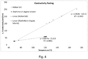
- the conductivity of NaI in a molten salt positive electrolyte AlCl 3 was compared to the conductivity of NaI in an organic solvent solution that included N-methyl formamide.
- the molten salt positive electrolyte had a general formula of NaAl x l y Cl z .
- the conductivity of Nal in a molten salt positive elcctrolyte was approximately three times the conductivity of the organic solvent-based electrolyte at 120 °C, as shown in Fig. 4 .
- Cells utilizing a molten salt positive electrolyte will be more energy dense due to higher molarity of NaI.
- cells utilizing a molten salt positive electrolyte are safer than organic solvent based positive electrolyte solutions because if molten sodium happens to contact the molten salt positive electrolyte, the chemical reaction would only produce non-flammable salts.
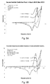
- a sodium-iodine secondary cell was prepared as described herein containing sodium iodide in molten AlCl 3 in a 60:40 NaI:AlCl 3 ratio (a "basic" electrolyte). Tungsten wire was used as the positive current collector. NaSICON was used to separate a molten sodium negative electrode from the positive electrode/positive electrolyte. The oxidation of iodide was measured and found to produce two oxidation peaks, consistent with Battery Chemistry 1 and Battery Chemistry 2, described herein. Experimental results arc shown in Fig. 5A . The oxidation peaks were found to be reversible.
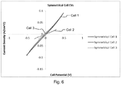
- symmetrical sodium-iodine secondary cells were prepared to te reversibility of the oxidation / reduction reactions that occur in the positive electr positive electrolyte.
- the symmetrical cells were prepared as set forth in Table 2, below:
- FIG. 6 A graph of the current vs. voltage for the operation of the symmetrical cells is shown in Fig. 6 . Because there is little or no hysteresis shown in Fig. 6 , it may be concluded that the oxidation / reduction reactions that occur in the positive electrode / positive electrolyte arc highly reversible.
Description
- The disclosed invention relates to an intermediate temperature, sodium - halogen secondary cell (or rechargeable battery) with a sodium ion conductive electrolyte membrane and a positive electrolyte that comprises one or more sodium haloaluminate salts and a sodium halide. In some disclosed embodiments, the battery system utilizes a molten eutectic mixture of sodium haloaluminate salts having a relatively low melting point.
- Batteries are known devices that are used to store and release electrical energy for a variety of uses. In order to produce electrical energy, batteries typically convert chemical energy directly into electrical energy. Generally, a single battery includes one or more galvanic cells, wherein each of the cells is made of two half-cells that arc electrically isolated except through an external circuit. During discharge, electrochemical reduction occurs at the cell's positive electrode, while electrochemical oxidation occurs at the cell's negative electrode. While the positive electrode and the negative electrode in the cell do not physically touch each other, they arc generally chemically connected by at least one (or more) ionically conductive and electrically insulative electrolytes, which can either be in a solid state, a liquid state, or in a combination of such states. When an external circuit, or a load, is connected to a terminal that is connected to the negative electrode and to a terminal that is connected to the positive electrode, the battery drives electrons through the external circuit, while ions migrate through the electrolyte.
- Batteries can be classified in a variety of manners. For example, batteries that are completely discharged only once arc often referred to as primary batteries or primary cells. In contrast, batteries that can be discharged and recharged more than once are often referred to as secondary batteries or secondary cells. The ability of a cell or battery to be charged and discharged multiple times depends on the Faradaic efficiency of each charge and discharge cycle.
- While rechargeable batteries based on sodium can comprise a variety of materials and designs, most, if not all, sodium batteries that require a high Faradaic efficiency employ a solid primary electrolyte separator, such as a solid ceramic primary electrolyte membrane. The principal advantage of using a solid ceramic primary electrolyte membrane is that the Faradaic efficiency of the resulting cell approaches 100%. Indeed, in almost all other cell designs, electrode solutions in the cell are able to intermix over time and, thereby, cause a drop in Faradaic cfficicncy and loss of battery capacity.
- The primary electrolyte separators used in sodium batteries that require a high Faradaic efficiency often consist of ionically conductive polymers, porous materials infiltrated with ionically conductive liquids or gels, or dense ceramics. In this regard, many rechargeable sodium batteries that are presently available for commercial applications comprise a molten sodium metal negative electrode, a sodium β"-alumina ceramic electrolyte separator, and a molten positive electrode, which may include a composite of molten sulfur and carbon (called a sodium/sulfur cell). Because these conventional high temperature sodium-based rechargeable batteries have relatively high specific energy densities and only modest power densities, such rechargeable batteries are typically used in certain specialized applications that require high specific energy densities where high power densities arc typically not encountered, such as in stationary storage and uninterruptable power supplies.
- Despite the beneficial characteristics associated with some conventional sodium-based rechargeable batteries, such batteries may have significant shortcomings. In one example, because the sodium β"-alumina ceramic electrolyte separator is typically more conductive and is better wetted by molten sodium at a temperature in excess of about 270° C and/or because the molten positive electrode typically requires relatively high temperatures (e.g., temperatures above about 170° or 180° C) to remain molten, many conventional sodium-based rechargeable batteries operate at temperatures higher than about 270° C and arc subject to significant thermal management problems and thermal sealing issues. For example, some sodium-based rechargeable batteries may have difficulty dissipating heat from the batteries or maintaining the negative electrode and the positive electrode at the relatively high operating temperatures. In another example, the relatively high operating temperatures of some sodium-based batteries can create significant safety issues. In still another example, the relatively high operating temperatures of some sodium-based batteries require their components to be resistant to, and operable at, such high temperatures. Accordingly, such components can be relatively expensive. In yet another example, because it may require a relatively large amount of energy to heat some conventional sodium-based batteries to the relatively high operating temperatures, such batteries can be expensive to operate and energy inefficient.
- Thus, while sodium-based rechargeable batteries are available, challenges with such batteries also exist, including those previously mentioned. Accordingly, it would be an improvement in the art to augment or even replace certain conventional sodium-based rechargeable batteries with other sodium-based rechargeable batteries that operate effectively at intermediate temperatures.
-
FR 2115522 -
US 4546055 discloses an electrochemical cell that is provided with a molten sodium anode and a molten sodium aluminium halide salt electrolyte. The cathode comprises FeCl2, NiCl2, CoCl2 or CrCl2 as active cathode substance dispersed in an electronically conductive electrolyte-permeable matrix which is impregnated by the electrolyte. Between the anode and the electrolyte, and isolating them from each other, is a solid conductor of sodium ions or a micromolecular sieve which contains sodium sorbed therein. The proportions of sodium and aluminium ions in the electrolyte are selected so that the solubility of the active cathode substance in the electrolyte is at or near its minimum. -
US 2014/030571 discloses a secondary cell having a negative electrode compartment and a positive electrode compartment, which are separated by an alkali ion conductive electrolyte membrane. An alkali metal negative electrode disposed in the negative electrode compartment oxidizes to release alkali ions as the cell discharges and reduces the alkali ions to alkali metal during recharge. The positive electrode compartment includes a positive electrode contacting a positive electrode solution that includes an alkali metal compound and a metal halide. The alkali metal compound can be selected from an alkali halide and an alkali pseudo-halide. During discharge, the metal ion reduces to form metal plating on the positive electrode. As the cell charges, the metal plating oxidizes to strip the metal plating to form metal halide or pseudo halide or corresponding metal complex. -
US 3877984 discloses a secondary battery utilizing a molten alkali metal negative reactant, a metal chloride positive reactant, a molten alkali metal chloraluminate electrolyte and a selectively-ionically-conductive separator positioned between the negative and the positive reactants. - The present invention provides a sodium-halogen secondary cell, comprising:
- a negative electrode compartment comprising a negative electrode that comprises metallic sodium in molten or solid state, wherein the negative electrode electrochemically oxidizes to release sodium ions during discharge and electrochemically reduces sodium ions to form sodium metal during recharge;
- a positive electrode comprising NaX disposed in a mixed molten positive electrolyte comprising at least two different NaAlX4 salts and is represented by the general formula NaAlX'4-δX"δ, where 0 < δ < 4, wherein X' and X" are different halogens selected from Cl, Br and I; and
- a sodium ion conductive solid electrolyte membrane that separates the negative electrode from the liquid positive electrode solution;
- the overall battery chemistry of the sodium-halogen secondary cell is 2Na + X2 ↔ 2Na+ + 2X- and
- the positive electrode comprises NaX or a mixture of NaX compounds present in a molar ratio to the mixed molten salt positive electrolyte ranging from 1:1 to 3:1 of NaX : NaAlX'4-δX"δ.
- Examples of sodium-halogen secondary cells are disclosed in Applicant's copending
U.S. Patent Application No. 14/019,651 , published asU.S. Publication No. 2014/0065456 entitled "Sodium-Halogen Secondary Cell." The disclosed secondary cells include a positive electrode compartment housing a current collector disposed in a liquid positive electrode solution. Some examples of suitable positive electrode solution materials include organic solvents such as dimethyl sulfoxide, NMF (N-methylformamide), and ionic liquids. - The present disclosure provides an improvement to the positive electrode solution of the sodium-halogen secondary cells disclosed in Applicant's copending application. In some disclosed embodiments, the battery system utilizes a molten eutectic mixture of sodium haloaluminate salts having a relatively low melting point.
- A sodium ion conductive solid electrolyte separates the negative electrode and the liquid positive electrode solution. In a non-limiting embodiment, the sodium ion conductive solid electrolyte comprises a NaSICON electrolyte material. The NaSICON electrolyte material has high sodium conductivity at cell operating temperatures.
- In one non-limiting embodiment, the battery operates at a temperature in the range from 80 °C to 210 °C.
- The rechargeable sodium-halogen battery includes a negative electrode comprising metallic sodium in molten or solid state. The positive electrode comprises NaX, where X is a halogen selected from Cl, Br and I. The positive electrode is disposed in a molten salt positive electrolyte comprising a mixture of at least two AlX3 salts that can be represented by the formula NaAlX'4-δ, where 0 < δ <4, wherein X' and X" are different halogens selected from Cl, Br and I.
- The mixed molten salt positive electrolyte comprises at least two salts of the general formula NaAlX'4 and NaAlX"4 at various molar ratios, wherein X' and X" are different halogens selected from Cl, Br and I. In one non-limiting embodiment, the molar ratio of NaAlX'4 to NaAlX"4 is in the range of 9:1 to 1:9 with corresponding δ values of 0.4 to 3.6.
- The positive electrode comprises NaX or a mixture of NaX compounds added in a molar ratio to the mixed molten salt positive electrolyte ranging from 1:1 to 3:1 of NaX : NaAlX'4-δX"δ. The excess NaX renders the positive electrolyte highly basic. At cell operating temperatures, the positive electrode and mixed molten salt positive electrolyte is a molten liquid or a two phase mixture wherein the mixed molten salt positive electrolyte is predominantly a liquid phase and the NaX or mixture of NaX compounds is a solid phase.
In other embodiments, the positive electrode is disposed in a mixed molten salt positive electrolyte comprising at least three salts that can be represented by the formula where X', X" and X''' are three different halogens selected from Cl, Br, and I, where 0 < 6 < 4,

- The disclosed sodium haloaluminate molten salts arc highly conductivc at relatively low temperatures enabling the sodium-halogen battery to be highly efficient and reversible. These features and advantages of the present embodiments will become more fully apparent from the following description and appended claims.
- In order that the manner in which the above-recited and other features and advantages of the invention are obtained will be readily understood, a more particular description of the invention briefly described above will be rendered by reference to specific embodiments thereof that are illustrated in the appended drawings. Understanding that these drawings depict only typical embodiments of the invention and are not therefore to be considered to be limiting of its scope, the invention will be described and explained with additional specificity and detail through the use of the accompanying drawings in which:
-
Fig. 1 depicts a schematic diagram of a representative embodiment of a molten sodium-halogen secondary cell, wherein the cell is in the process of being discharged. -
Fig. 2 depicts a schematic diagram of a representative embodiment of the molten sodium-halogen secondary cell, wherein the cell is in the process of being recharged. -
Fig. 3A depicts one potential reaction, designatedBattery Chemistry 1, at the positive current collector. -
Fig. 3B depicts another potential reaction, designatedBattery Chemistry 2, at the positive current collector. -
Fig. 4 is a graph comparing the conductivity of NaI in a molten salt electrolyte and in an organic solvent as a function of temperature. -
Figs. 5A and 5B are graphs comparing the oxidation of iodide in a sodium-iodine secondary cell containing NaI in AlCl3 at basic and acidic ratios of NaI:AlCl3. -
Fig. 6 is a graph of the current vs. voltage for the operation of the symmetrical cells described in Example 3. - Reference throughout this specification to "one embodiment," "an embodiment," or similar language means that a particular feature, structure, or characteristic described in connection with the embodiment is included in at least one embodiment of the present invention. Thus, appearances of the phrases "in one embodiment," "in an embodiment," "in another embodiment," and similar language throughout this specification may, but do not necessarily, all refer to the same embodiment. Additionally, while the following description refers to several embodiments and examples of the various components and aspects of the described invention, all of the described embodiments and examples are to be considered, in all respects, as illustrative only and not as being limiting in any manner.
- Furthermore, the described features, structures, or characteristics of the invention may be combined in any suitable manner in one or more embodiments. In the following description, numerous specific details are provided, such as examples of suitable sodium-based negative electrodes, liquid positive electrode solutions, current collectors, sodium ion conductive electrolyte membranes, etc., to provide a thorough understanding of embodiments of the invention. One having ordinary skill in the relevant art will recognize, however, that the invention may be practiced without one or more of the specific details, or with other methods, components, materials, and so forth. In other embodiments, well-known structures, materials, or operations are not shown or described in detail to avoid obscuring aspects of the invention. The Invention is set out In the appended claims.
- As stated above, secondary cells can be discharged and recharged and this specification describes cell arrangements and methods for both states. Although the term "recharging" in its various forms implies a second charging, one of skill in the art will understand that discussions regarding recharging would be valid for, and applicable to, the first or initial charge, and vice versa. Thus, for the purposes of this specification, the terms "recharge," "recharged," and "rechargeable" shall be interchangeable with the terms "charge," "charged," and "chargeable," respectively.
- The embodiments according to the Invention provide a sodium-halogen secondary cell, which includes a molten or solid state sodium negative electrode and a sodium halide positive electrode disposed in a molten positive electrolyte that comprises one or more haloaluminatc salts. According to the invention, the secondary cell utilizes as the positive electrolyte a molten eutectic mixture of sodium haloaluminate salts having a relatively low melting point. Although the described cell can comprise any suitable component,
Figure 1 shows a representative embodiment in which the sodiumsecondary cell 10 comprises anegative electrode compartment 15 that includes a sodium metalnegative electrode 20 and apositive electrode compartment 25 that comprises a sodium halide positive electrode. The positive electrode includes acurrent collector 30 disposed in apositive electrolyte 35 comprising one or more molten haloaluminate salts (AlCl3, AlBr3, and AlI3) A sodium ionconductive electrolyte membrane 40 separates the negative electrode from the liquid positive electrode solution andpositive electrolyte 35. The sodium ionconductive electrolyte membrane 40 separates a first terminal 45 from asecond terminal 50. To provide a better understanding of the describedcell 10, a brief description of how the cell functions is provided below. Following this discussion, each of the cell's components shown inFigure 1 is discussed in more detail. - Turning now to the manner in which the sodium
secondary cell 10 functions, the cell can function in virtually any suitable manner. In one example,Figure 1 illustrates that as thecell 10 is discharged and electrons (c-) flow from the negative electrode 20 (e.g., via the first terminal 45), sodium is oxidized from thenegative electrode 20 to form sodium ions (Na+).Figure 1 shows that these sodium ions arc respectively transported from the sodiumnegative electrode 20, through the sodium ionconductive membrane 40, and to thepositive electrolyte 35. - In a contrasting example.
Figure 2 shows that as thesecondary cell 10 is recharged and electrons (c-) flow into the sodiumnegative electrode 20 from an external power source (not shown), such as a recharger, the chemical reactions that occurred when thecell 10 was discharged (as shown inFigure 1 ) are reversed. Specifically,Figure 2 shows that as thecell 10 is recharged, sodium ions (Na) arc respectively transported from thepositive electrolyte 35, through theelectrolyte membrane 40, and to thenegative electrode 20, where the sodium ions are reduced to form sodium metal (Na). - Referring now to the various components of the
cell 10, the cell, as mentioned above comprises anegative electrode compartment 15 and apositive electrode compartment 25. In this regard, the two compartments can be any suitable shape and have any other suitable characteristic that allows thecell 10 to function as intended. By way of example, the negative electrode and the positive electrode compartments can be tubular, rectangular, or be any other suitable shape. Furthermore, the two compartments can have any suitable spatial relationship with respect to each other. For instance, whileFigure 2 shows that thenegative electrode compartment 15 and thepositive electrode compartment 25 can be adjacent to each other, in other embodiments (not shown), one compartment (e.g., the negative electrode compartment) is disposed, at least partially, in the other compartment (e.g., the positive electrode compartment), while the contents of the two compartments remain separated by theelectrolyte membrane 40 and any other compartmental walls. - With respect to the
negative electrode 20, thecell 10 can comprise any suitable sodiumnegative electrode 20 that allows thecell 10 to function (e.g., be discharged and recharged) as intended. Some examples of suitable sodium negative electrode materials include, but arc not limited to, a sodium sample that is substantially pure and a sodium alloy comprising any other suitable sodium-containing negative electrode material. In certain embodiments, however, the negative electrode comprises or consists of an amount of sodium that is substantially pure. In such embodiments, because the melting point of pure sodium is around 98° C, the sodium negative electrode will become molten above that temperature. - With respect to the positive
current collector 30, thepositive electrode compartment 25 can comprise any suitable positive electrode that allows the cell to be charged and discharged as intended. For instance, the positive electrode can comprise virtually anycurrent collector 30 in combination with a halogen, shown generically as "X" inFigs. 1 and 2 , in apositive electrolyte 35 comprising at least two sodium haloaluminate salts. Thecurrent collector 30 can be disposed in any suitable location in thepositive electrode compartment 25 that allows thecell 10 to function as intended. - With respect to the
current collector 30, thecell 10 can comprise any suitable current collector that allows the cell to be charged and discharged as intended. For instance, the current collector can comprise virtually any current collector configuration that has been successfully used in a sodium-based rechargeable battery system. In some embodiments, the current collector comprises at least one of wires, felts, foils, plates, parallel plates, tubes, meshes, mesh screens, foams, and/or other suitable current collector configuration. It will be appreciated by those of skill in the art that the foam may include, without limitation, metal foams and carbon foams. Indeed, in some embodiments, the current collector comprises a configuration having a relatively large surface area which may include one or more mesh screens and metal foams. - The
current collector 30 can comprise any suitable material that allows thecell 10 to function as intended. In this regard, some non-limiting examples of suitable current collector materials include tungsten, stainless steel, carbon, molybdenum, titanium, platinum, copper, nickel, zinc, a sodium intercalation material (e.g., NaXMnO2, etc.), nickel foam, nickel, a sulfur composite, a sulfur halide (e.g., sulfuric chloride), and/or another suitable material. Furthermore, these materials may coexist or exist in combinations. In some embodiments, however, the current collector comprises tungsten, carbon, molybdenum, titanium. - In some non-limiting embodiments, the reactions that may occur at the
negative electrode 20, the positive electrode/current collector 30, and the overall reaction as thecell 10 is discharged may occur in at least two steps. These two potential reactions arc shown below and designated Battery Chemistry 1 (shown schematically inFig. 3A for battery recharge) and Battery Chemistry 2 (shown schematically inFig. 3B for battery recharge). It has been observed that these reactions may be individual steps of a multi-step reaction, or depending upon the battery conditions, one step may be favored over another step. - Negative electrode Na ↔ Na- + 1e-
- Positive electrode X3 - + 2e- ↔ 3X- (Battery Chemistry 1)
-
Positive electrode 3X2 + 2e- ↔ 2X3 - (Battery Chemistry 2) - Overall 2Na + X3 - ↔ 2Na+ + 3X- (Battery Chemistry 1)
- Overall 2Na + 3X2 ↔ 2Na+ + 2X3 - (Battery Chemistry 2)
- Where X comprises iodine, bromine, or chlorine.
- Where X comprises iodine, the
cell 10 may have the following chemical reactions and the following theoretical voltage (V vs. SHE (standard hydrogen electrode)) and theoretical specific energy (Wh/kg): - Negative electrode Na ↔ Na- + 1c (-2.71V)
- Positive electrode I3 - + 2e- ↔ 3I- (0.29V, Chemistry 1)
- Positive electrode 3I2 + 2e- ↔ 2I3 - (0.74V, Chemistry 2)
- Overall 2Na + I3 - ↔ 2Na+ + 3I- (2.8V, Chemistry 1) (388 Wh/kg)
- Overall 2Na + 3I2 ↔ 2Na' + 2I3 - (3.25V, Chemistry 2) (193 Wh/kg)
- Where X is iodine, the charging reactions at the positive electrode may occur in two steps: 1) iodide to triiodide and 2) triiodide to iodine. Similarly, discharging reactions at the positive electrode may occur in two steps: 1) iodine to triiodide and 2) triiodide to iodide. Alternatively, the charging and discharging reactions may occur using the combination of reaction chemistries above.
- Where X is bromine, the
cell 10 may have the following chemical reactions and the following theoretical voltage (V vs. SHE) and theoretical specific energy (Wh/kg): - Negative electrode Na ↔ Na- + 1e- (-2.71V)
- Positive electrode Br3 - + 2e- ↔ 3Br- (0.82V, Chemistry 1)
- Positive electrode 3Br2 + 2e- ↔ 2Br3 - (1.04V, Chemistry 2)
- Overall 2Na + Br3 - ↔ 2Na- + 3Br- (3.53V, Chemistry 1) (658 Wh/kg)
- Overall 2Na + 3Br2 ↔ 2Na+ + 2Br3 - (3.75V, Chemistry 2) (329 Wh/kg)
- The charging reactions at the positive electrode may occur in two steps: 1) bromide to tribromide and 2) tribromide to bromine. Similarly, discharging reactions at the positive electrode may occur in two steps: 1) bromine to tribromide and 2) tribromide to bromide. Alternatively, the charging and discharging reactions may occur using the combination of reaction chemistries above.
- It will be appreciated by those of skill in the art that an alternative positive electrode chemistry may include:
- Positive electrode X2 + 2e- ↔ 2X- (Battery Chemistry 3)
- With an overall battery chemistry of:
- Overall 2Na + X2 ↔ 2Na+ + 2X- (Battery Chemistry 3)
- With regards now to the sodium ion
conductive electrolyte membrane 40, the membrane can comprise any suitable material that selectively transports sodium ions and permits thecell 10 to function with apositive electrolyte 35. In some embodiments, the electrolyte membrane comprises a NaSICON-type (sodium Super Ion CONductive) material. Where the electrolyte membrane comprises a NaSICON-type material, the NaSICON-type material may comprise any known or novel NaSICON-type material that is suitable for use with the describedcell 10. Some suitable examples of NaSICON-type compositions include, but are not limited to, Na3Zr2Si2PO12, Na1+xSixZr2P3-xO12 (where x is between about 1.6 and about 2.4), Y-doped NaSICON (Na1-x+yZr2-yYySixP3-xO12, Na1-xZr2-yYy SixP3-xO12-y (where x = 2, y = 0.12)), Na1-xZr2SixP3-xO12 (where x is between about 0 and about 3, and in some cases between about 2 and about 2.5), and Fe-doped NaSICON (Na3Zr2/3Fe4/3P3O12). Indeed, in certain embodiments, the NaSICON-type membrane comprises Na3Si2Zr2PO12 In other embodiments, the NaSICON-type membrane comprises one or more NaSELECT x materials, produced by Ccramatcc, Inc. in Salt Lake City, Utah. - The positive electrode comprises NaX, where X is a halogen selected from Cl, Br and I. The positive electrode is preferably NaI.
- The positive electrode is disposed in a molten salt positive electrolyte comprising AlX3, NaX and AlX3 combine to form NaAlX4 as follows:
NaX + AlX3 ↔ NaAlX4
- According to the invention, the positive electrode is combined with a mixture of at least two AlX3 salts. The combination of positive electrode and positive electrolyte can be represented by the general formula NaAlX'4-δX"δ, where 0 < δ < 4, wherein X' and X" are different halogens selected from Cl, Br and I.
- The mixed molten salt positive electrolyte comprises at least two salts of the general formula NaAlX'4 and NaAlX"4 at various molar ratios, wherein X' and X" arc different halogens selected from Cl, Br and I. In one non-limiting embodiment, the molar ratio of NaAlX'4 to NaAlX"4 is in the range of 9:1 to 1:9 with corresponding δ values of 0.4 to 3.6.
- The positive electrode comprises NaX or a mixture of NaX compounds added in a molar ratio to the mixed molten salt positive electrolyte ranging from 1:1 to 3:1 of NaX : NaAlX'4-δX"δ. The excess NaX renders the positive electrolyte highly basic. At cell operating temperatures, the positive electrode and mixed molten salt positive electrolyte is a molten liquid or a two phase mixture wherein the mixed molten salt positive electrolyte is predominantly a liquid phase and the additional NaX or mixture of NaX compounds is a solid phase.
- The following Table 1 illustrates some non-limiting combinations of NaX and AlX3 to form NaAlX4.
Table 1 NaX \ AlX3 AlCl3 AlBr3 AlI3 NaCl NaAlCl4 NaAlBr3Cl NaAlI3Cl NaBr NaAlCl3Br NaAlBr4 NaAlI3Br Nal NaAlCl3I NaAlBr3I NaAlI4 - In other embodiments, the positive electrode is disposed in a mixed molten salt positive electrolyte comprising at least three salts that can be represented by the formula where X', X" and X''' are three different halogens selected from Cl, Br, and I, where 0 < δ < 4,


- In some embodiments, the
positive electrolyte 35 also comprises one or more halogens and/or halides. In this regard, the halogens and halides, as well polyhalides and/or metal halides that form therefrom (e.g., where thecurrent collector 30 comprises a metal, such as copper, nickel, zinc, ctc. (as discussed below)) can perform any suitable function, including, without limitation, acting as the positive electrode as thecell 10 operates. Some examples of suitable halogens include bromine, iodine, and chlorine. Similarly, some examples of suitable halides include bromide ions, polybromidc ions, iodide ions, polyiodide ions, chloride ions, and polychloride ions. While the halogens/halides can be introduced into the positive electrode solution in any suitable manner, in some embodiments, they are added as NaX, wherein X is selected from Br, I, Cl, etc. - With reference now to the
terminals cell 10 can comprise any suitable terminals that are capable of electrically connecting the cell with an external circuit (not shown), including without limitation, to one or more cells. In this regard, the terminals can comprise any suitable material, be of any suitable shape, and be of any suitable size. - In addition to the aforementioned components, the
cell 10 can optionally comprise any other suitable component. By way of non-limiting illustrationFigures 1 and 2 show an embodiment in which thecell 10 comprises aheat management system cell 10 generally. In such embodiments, the cell can comprise any suitable type of heat management system that is capable of maintaining the cell within a suitable operating temperature range. Some examples of such heat management systems include, but are not limited to, a heater, a cooler, one or more temperature sensors, and appropriate temperature control circuitry. - The described
cell 10 may function at any suitable operating temperature. In other words, as the cell is discharged and/or recharged, the sodium negative electrode and the positive electrolyte may have any suitable temperature. The negative and positive electrode compartments may operate at the same or different temperatures. Indeed, in some embodiments, the cell functions at an intermediate operating temperature in the range from 80 °C to 210 °C. In other embodiments, the cell may function at an intermediate operating temperature in the range from about 110 °C to about 180 °C. In yet another embodiment, the operating temperature of the cell in the range of about 150 °C to about 170 °C. - The following examples are given to illustrate various embodiments within, and aspects of, the scope of the present invention as set out in the appended claims. These are given by way of example only, and it is understood that the following examples are not comprehensive or exhaustive of the many types of embodiments of the present invention that can be prepared in accordance with the present invention.
- The conductivity of NaI in a molten salt positive electrolyte AlCl3 was compared to the conductivity of NaI in an organic solvent solution that included N-methyl formamide. The molten salt positive electrolyte had a general formula of NaAlxlyClz. The conductivity of Nal in a molten salt positive elcctrolyte was approximately three times the conductivity of the organic solvent-based electrolyte at 120 °C, as shown in
Fig. 4 . Cells utilizing a molten salt positive electrolyte will be more energy dense due to higher molarity of NaI. Furthermore, cells utilizing a molten salt positive electrolyte are safer than organic solvent based positive electrolyte solutions because if molten sodium happens to contact the molten salt positive electrolyte, the chemical reaction would only produce non-flammable salts. - A sodium-iodine secondary cell was prepared as described herein containing sodium iodide in molten AlCl3 in a 60:40 NaI:AlCl3 ratio (a "basic" electrolyte). Tungsten wire was used as the positive current collector. NaSICON was used to separate a molten sodium negative electrode from the positive electrode/positive electrolyte. The oxidation of iodide was measured and found to produce two oxidation peaks, consistent with
Battery Chemistry 1 andBattery Chemistry 2, described herein. Experimental results arc shown inFig. 5A . The oxidation peaks were found to be reversible. Additional tests were performed using an "acidic" electrolyte comprising sodium iodide in molten AlCl3 in a 40:60 NaI:AlCl3 ratio. Experimental results are shown inFig. 5B . The results suggest that the s oxidation peak in the basic electrolyte occurs at a similar potential as the first : oxidation peak in the acidic electrolyte. The reduction peak in acidic electrolyte occur higher potential. This suggests that whether the electrolyte is acidic or basic affec potential of I2 generation. - Three symmetrical sodium-iodine secondary cells were prepared to te reversibility of the oxidation / reduction reactions that occur in the positive electr positive electrolyte. The symmetrical cells were prepared as set forth in Table 2, below:

- The symmetrical cells were operated as set forth in Table 3, below:

- A graph of the current vs. voltage for the operation of the symmetrical cells is shown in
Fig. 6 . Because there is little or no hysteresis shown inFig. 6 , it may be concluded that the oxidation / reduction reactions that occur in the positive electrode / positive electrolyte arc highly reversible.
Claims (10)
- A sodium-halogen secondary cell, comprising:a negative electrode compartment comprising a negative electrode that comprises metallic sodium in molten or solid state, wherein the negative electrode electrochemically oxidizes to release sodium ions during discharge and electrochemically reduces sodium ions to form sodium metal during recharge;a positive electrode comprising NaX disposed in a mixed molten positive electrolyte comprising at least two different NaAlX4 salts and is represented by the general formula NaAlX'4-6X"δ, where 0 < δ < 4, wherein X' and X" are different halogens selected from Cl, Br and I; anda sodium ion conductive solid electrolyte membrane that separates the negative electrode from the liquid positive electrode solution;wherein;the overall battery chemistry of the sodium-halogen secondary cell is 2Na + X2 ↔ 2Na+ + 2X- andthe positive electrode comprises NaX or a mixture of NaX compounds present in a molar ratio to the mixed molten salt positive electrolyte ranging from 1:1 to 3:1 of NaX : NaAlX'4-δX"δ.
- The secondary cell of claim 1, wherein the molten salt positive electrolyte comprises three different NaAlX4 salts and is represented by the general formula where X', X" and X''' are three different halogens selected from Cl, Br, and I, where 0 < δ< 4,


wherein the positive electrode comprises NaX or a mixture of NaX compounds present in a molar ratio to the mixed molten salt positive electrolyte ranging from 1:1 to 3:1 of
- The secondary cell of claim 2, wherein the positive electrode and the ωmolten positive electrolyte are in the form of a mixed molten salt comprising at least three salts of the formula NaAlCl4, NaAlBr4, and NaAlI4, at various molar ratios.
- The secondary cell of any preceding claim, wherein the secondary cell operates at a temperature between 80 °C and 210° C.
- The secondary cell of any preceding claim, wherein the electrolyte membrane comprises a NaSICON-type material.
- The secondary cell of claim 1, wherein the additional NaX is present as a solid phase within the positive electrode.
- The secondary cell of any preceding claim wherein the positive electrode comprises a current collector.
- The secondary cell of claim 7, wherein the positive electrode comprises a current collector comprising at least one of carbon, tungsten, molybdenum, and titanium.
- The secondary cell of claim 7 or claim 8, wherein the current collector comprises at least one of wires, felts, foils, plates, parallel plates, tubes, meshes, mesh screens, and foams.
- The sodium-halogen secondary cell of any preceding claim, comprising:a negative electrode compartment comprising a negative electrode that comprises metallic sodium in molten state, wherein the negative electrode electrochemically oxidizes to release sodium ions during discharge and electrochemically reduces sodium ions to form sodium metal during recharge;a positive electrode comprising NaI disposed in a mixed molten positive electrolyte comprising at least two different NaAlX4 salts and is represented by the general formula NaAlX'4-δX"δ, where 0 < δ < 4, wherein X' and X" are different halogens selected from Cl, Br and I; anda sodium ion conductive solid electrolyte membrane that separates the negative electrode from the liquid positive electrode solution;wherein the overall battery chemistry of the sodium-halogen secondary cell is 2Na + 12 ↔ 2Na+ + 2I-; andthe positive electrode comprises NaI present in a molar ratio to the mixed molten salt positive electrolyte ranging from 1:1 to 3:1 of NaI : NaAlX'4-δX"δ.
Applications Claiming Priority (2)
| Application Number | Priority Date | Filing Date | Title |
|---|---|---|---|
| US201462087507P | 2014-12-04 | 2014-12-04 | |
| PCT/US2015/063244 WO2016089902A1 (en) | 2014-12-04 | 2015-12-01 | Sodium-halogen secondary cell |
Publications (3)
| Publication Number | Publication Date |
|---|---|
| EP3227951A1 EP3227951A1 (en) | 2017-10-11 |
| EP3227951A4 EP3227951A4 (en) | 2018-08-01 |
| EP3227951B1 true EP3227951B1 (en) | 2019-08-28 |
Family
ID=56092343
Family Applications (1)
| Application Number | Title | Priority Date | Filing Date |
|---|---|---|---|
| EP15865518.3A Active EP3227951B1 (en) | 2014-12-04 | 2015-12-01 | Sodium-halogen secondary cell |
Country Status (4)
| Country | Link |
|---|---|
| EP (1) | EP3227951B1 (en) |
| JP (1) | JP6659691B2 (en) |
| KR (1) | KR20170092619A (en) |
| WO (1) | WO2016089902A1 (en) |
Families Citing this family (1)
| Publication number | Priority date | Publication date | Assignee | Title |
|---|---|---|---|---|
| US10601062B2 (en) * | 2015-10-01 | 2020-03-24 | Dynantis Corp. | Sodium metal batteries with intercalating cathode |
Family Cites Families (11)
| Publication number | Priority date | Publication date | Assignee | Title |
|---|---|---|---|---|
| US3632448A (en) * | 1968-07-29 | 1972-01-04 | Exxon Research Engineering Co | Aluminum-halogen secondary battery method with molten electrolyte |
| FR2115522A5 (en) * | 1970-11-23 | 1972-07-07 | Accumulateurs Fixes | Sodium-sodium halide cell - using aluminium chloride-sodium halide complexes |
| US3877984A (en) * | 1974-04-24 | 1975-04-15 | Esb Inc | Alkali metal-metal chloride battery |
| ZA828603B (en) * | 1981-12-10 | 1983-09-28 | South African Inventions | Electrochemical cell |
| KR101635850B1 (en) * | 2009-03-27 | 2016-07-04 | 도쿄 유니버시티 오브 사이언스 에듀케이셔널 파운데이션 애드미니스트레이티브 오거니제이션 | Sodium ion secondary battery |
| DK2497133T3 (en) * | 2009-11-05 | 2019-04-08 | Field Upgrading Usa Inc | SODIUM BASED SOLID SECONDARY CELL WITH A CERAMIC SODIUM CONDUCTIVE SEPARATOR |
| US20130052525A1 (en) * | 2011-08-24 | 2013-02-28 | Sumitomo Chemical Company, Limited | Sodium secondary battery |
| US10224577B2 (en) * | 2011-11-07 | 2019-03-05 | Field Upgrading Usa, Inc. | Battery charge transfer mechanisms |
| US20130196224A1 (en) * | 2012-02-01 | 2013-08-01 | Battelle Memorial Institute | Intermediate Temperature Sodium Metal-Halide Energy Storage Devices |
| WO2013154349A1 (en) * | 2012-04-10 | 2013-10-17 | Sk Innovation Co.,Ltd. | Sodium secondary battery |
| JP6436906B2 (en) * | 2012-09-06 | 2018-12-12 | フィールド アップグレーディング ユーエスエー・インク | Sodium-halogen secondary battery |
-
2015
- 2015-12-01 JP JP2017529996A patent/JP6659691B2/en active Active
- 2015-12-01 WO PCT/US2015/063244 patent/WO2016089902A1/en active Application Filing
- 2015-12-01 KR KR1020177017918A patent/KR20170092619A/en unknown
- 2015-12-01 EP EP15865518.3A patent/EP3227951B1/en active Active
Non-Patent Citations (1)
| Title |
|---|
| None * |
Also Published As
| Publication number | Publication date |
|---|---|
| JP6659691B2 (en) | 2020-03-04 |
| KR20170092619A (en) | 2017-08-11 |
| JP2017536683A (en) | 2017-12-07 |
| WO2016089902A1 (en) | 2016-06-09 |
| EP3227951A4 (en) | 2018-08-01 |
| EP3227951A1 (en) | 2017-10-11 |
Similar Documents
| Publication | Publication Date | Title |
|---|---|---|
| EP3284134B1 (en) | Sodium-aluminum battery with sodium ion conductive ceramic separator | |
| EP2893590B1 (en) | Sodium-halogen secondary cell | |
| US9537179B2 (en) | Intermediate temperature sodium-metal halide battery | |
| KR102217751B1 (en) | Low temperature battery with molten sodium-fsa electrolyte | |
| EP2973838B1 (en) | Low temperature secondary cell with sodium intercalation electrode | |
| EP3050153B1 (en) | Intermediate temperature sodium-metal halide battery | |
| US10854929B2 (en) | Sodium-halogen secondary cell | |
| EP3042415A1 (en) | Sodium-halogen secondary cell | |
| EP3227951B1 (en) | Sodium-halogen secondary cell | |
| US20150030896A1 (en) | Sodium-halogen secondary cell | |
| EP3180815A1 (en) | Na-fecl2 zebra type battery |
Legal Events
| Date | Code | Title | Description |
|---|---|---|---|
| STAA | Information on the status of an ep patent application or granted ep patent |
Free format text: STATUS: THE INTERNATIONAL PUBLICATION HAS BEEN MADE |
|
| PUAI | Public reference made under article 153(3) epc to a published international application that has entered the european phase |
Free format text: ORIGINAL CODE: 0009012 |
|
| STAA | Information on the status of an ep patent application or granted ep patent |
Free format text: STATUS: REQUEST FOR EXAMINATION WAS MADE |
|
| 17P | Request for examination filed |
Effective date: 20170703 |
|
| AK | Designated contracting states |
Kind code of ref document: A1 Designated state(s): AL AT BE BG CH CY CZ DE DK EE ES FI FR GB GR HR HU IE IS IT LI LT LU LV MC MK MT NL NO PL PT RO RS SE SI SK SM TR |
|
| AX | Request for extension of the european patent |
Extension state: BA ME |
|
| RAP1 | Party data changed (applicant data changed or rights of an application transferred) |
Owner name: FIELD UPGRADING LIMITED |
|
| RAP1 | Party data changed (applicant data changed or rights of an application transferred) |
Owner name: FIELD UPGRADING USA |
|
| RAP3 | Party data changed (applicant data changed or rights of an application transferred) |
Owner name: FIELD UPGRADING USA, INC. |
|
| DAV | Request for validation of the european patent (deleted) | ||
| DAX | Request for extension of the european patent (deleted) | ||
| A4 | Supplementary search report drawn up and despatched |
Effective date: 20180629 |
|
| RIC1 | Information provided on ipc code assigned before grant |
Ipc: H01M 4/58 20100101ALI20180625BHEP Ipc: H01M 10/39 20060101ALI20180625BHEP Ipc: H01M 4/38 20060101ALI20180625BHEP Ipc: H01M 4/66 20060101ALI20180625BHEP Ipc: H01M 4/70 20060101ALI20180625BHEP Ipc: H01M 10/054 20100101AFI20180625BHEP Ipc: H01M 4/13 20100101ALI20180625BHEP Ipc: H01M 10/0562 20100101ALI20180625BHEP |
|
| GRAP | Despatch of communication of intention to grant a patent |
Free format text: ORIGINAL CODE: EPIDOSNIGR1 |
|
| STAA | Information on the status of an ep patent application or granted ep patent |
Free format text: STATUS: GRANT OF PATENT IS INTENDED |
|
| RAP1 | Party data changed (applicant data changed or rights of an application transferred) |
Owner name: FIELD UPGRADING USA, INC. |
|
| INTG | Intention to grant announced |
Effective date: 20190326 |
|
| GRAJ | Information related to disapproval of communication of intention to grant by the applicant or resumption of examination proceedings by the epo deleted |
Free format text: ORIGINAL CODE: EPIDOSDIGR1 |
|
| STAA | Information on the status of an ep patent application or granted ep patent |
Free format text: STATUS: REQUEST FOR EXAMINATION WAS MADE |
|
| GRAR | Information related to intention to grant a patent recorded |
Free format text: ORIGINAL CODE: EPIDOSNIGR71 |
|
| GRAS | Grant fee paid |
Free format text: ORIGINAL CODE: EPIDOSNIGR3 |
|
| STAA | Information on the status of an ep patent application or granted ep patent |
Free format text: STATUS: GRANT OF PATENT IS INTENDED |
|
| INTC | Intention to grant announced (deleted) | ||
| GRAA | (expected) grant |
Free format text: ORIGINAL CODE: 0009210 |
|
| STAA | Information on the status of an ep patent application or granted ep patent |
Free format text: STATUS: THE PATENT HAS BEEN GRANTED |
|
| AK | Designated contracting states |
Kind code of ref document: B1 Designated state(s): AL AT BE BG CH CY CZ DE DK EE ES FI FR GB GR HR HU IE IS IT LI LT LU LV MC MK MT NL NO PL PT RO RS SE SI SK SM TR |
|
| INTG | Intention to grant announced |
Effective date: 20190719 |
|
| REG | Reference to a national code |
Ref country code: GB Ref legal event code: FG4D |
|
| REG | Reference to a national code |
Ref country code: CH Ref legal event code: EP |
|
| REG | Reference to a national code |
Ref country code: AT Ref legal event code: REF Ref document number: 1173539 Country of ref document: AT Kind code of ref document: T Effective date: 20190915 |
|
| REG | Reference to a national code |
Ref country code: IE Ref legal event code: FG4D |
|
| REG | Reference to a national code |
Ref country code: DE Ref legal event code: R096 Ref document number: 602015036944 Country of ref document: DE |
|
| REG | Reference to a national code |
Ref country code: NL Ref legal event code: MP Effective date: 20190828 |
|
| REG | Reference to a national code |
Ref country code: LT Ref legal event code: MG4D |
|
| PG25 | Lapsed in a contracting state [announced via postgrant information from national office to epo] |
Ref country code: FI Free format text: LAPSE BECAUSE OF FAILURE TO SUBMIT A TRANSLATION OF THE DESCRIPTION OR TO PAY THE FEE WITHIN THE PRESCRIBED TIME-LIMIT Effective date: 20190828 Ref country code: PT Free format text: LAPSE BECAUSE OF FAILURE TO SUBMIT A TRANSLATION OF THE DESCRIPTION OR TO PAY THE FEE WITHIN THE PRESCRIBED TIME-LIMIT Effective date: 20191230 Ref country code: SE Free format text: LAPSE BECAUSE OF FAILURE TO SUBMIT A TRANSLATION OF THE DESCRIPTION OR TO PAY THE FEE WITHIN THE PRESCRIBED TIME-LIMIT Effective date: 20190828 Ref country code: NL Free format text: LAPSE BECAUSE OF FAILURE TO SUBMIT A TRANSLATION OF THE DESCRIPTION OR TO PAY THE FEE WITHIN THE PRESCRIBED TIME-LIMIT Effective date: 20190828 Ref country code: NO Free format text: LAPSE BECAUSE OF FAILURE TO SUBMIT A TRANSLATION OF THE DESCRIPTION OR TO PAY THE FEE WITHIN THE PRESCRIBED TIME-LIMIT Effective date: 20191128 Ref country code: BG Free format text: LAPSE BECAUSE OF FAILURE TO SUBMIT A TRANSLATION OF THE DESCRIPTION OR TO PAY THE FEE WITHIN THE PRESCRIBED TIME-LIMIT Effective date: 20191128 Ref country code: LT Free format text: LAPSE BECAUSE OF FAILURE TO SUBMIT A TRANSLATION OF THE DESCRIPTION OR TO PAY THE FEE WITHIN THE PRESCRIBED TIME-LIMIT Effective date: 20190828 Ref country code: HR Free format text: LAPSE BECAUSE OF FAILURE TO SUBMIT A TRANSLATION OF THE DESCRIPTION OR TO PAY THE FEE WITHIN THE PRESCRIBED TIME-LIMIT Effective date: 20190828 |
|
| PG25 | Lapsed in a contracting state [announced via postgrant information from national office to epo] |
Ref country code: RS Free format text: LAPSE BECAUSE OF FAILURE TO SUBMIT A TRANSLATION OF THE DESCRIPTION OR TO PAY THE FEE WITHIN THE PRESCRIBED TIME-LIMIT Effective date: 20190828 Ref country code: IS Free format text: LAPSE BECAUSE OF FAILURE TO SUBMIT A TRANSLATION OF THE DESCRIPTION OR TO PAY THE FEE WITHIN THE PRESCRIBED TIME-LIMIT Effective date: 20191228 Ref country code: GR Free format text: LAPSE BECAUSE OF FAILURE TO SUBMIT A TRANSLATION OF THE DESCRIPTION OR TO PAY THE FEE WITHIN THE PRESCRIBED TIME-LIMIT Effective date: 20191129 Ref country code: AL Free format text: LAPSE BECAUSE OF FAILURE TO SUBMIT A TRANSLATION OF THE DESCRIPTION OR TO PAY THE FEE WITHIN THE PRESCRIBED TIME-LIMIT Effective date: 20190828 Ref country code: LV Free format text: LAPSE BECAUSE OF FAILURE TO SUBMIT A TRANSLATION OF THE DESCRIPTION OR TO PAY THE FEE WITHIN THE PRESCRIBED TIME-LIMIT Effective date: 20190828 Ref country code: ES Free format text: LAPSE BECAUSE OF FAILURE TO SUBMIT A TRANSLATION OF THE DESCRIPTION OR TO PAY THE FEE WITHIN THE PRESCRIBED TIME-LIMIT Effective date: 20190828 |
|
| REG | Reference to a national code |
Ref country code: AT Ref legal event code: MK05 Ref document number: 1173539 Country of ref document: AT Kind code of ref document: T Effective date: 20190828 |
|
| PG25 | Lapsed in a contracting state [announced via postgrant information from national office to epo] |
Ref country code: TR Free format text: LAPSE BECAUSE OF FAILURE TO SUBMIT A TRANSLATION OF THE DESCRIPTION OR TO PAY THE FEE WITHIN THE PRESCRIBED TIME-LIMIT Effective date: 20190828 |
|
| PG25 | Lapsed in a contracting state [announced via postgrant information from national office to epo] |
Ref country code: IT Free format text: LAPSE BECAUSE OF FAILURE TO SUBMIT A TRANSLATION OF THE DESCRIPTION OR TO PAY THE FEE WITHIN THE PRESCRIBED TIME-LIMIT Effective date: 20190828 Ref country code: PL Free format text: LAPSE BECAUSE OF FAILURE TO SUBMIT A TRANSLATION OF THE DESCRIPTION OR TO PAY THE FEE WITHIN THE PRESCRIBED TIME-LIMIT Effective date: 20190828 Ref country code: EE Free format text: LAPSE BECAUSE OF FAILURE TO SUBMIT A TRANSLATION OF THE DESCRIPTION OR TO PAY THE FEE WITHIN THE PRESCRIBED TIME-LIMIT Effective date: 20190828 Ref country code: DK Free format text: LAPSE BECAUSE OF FAILURE TO SUBMIT A TRANSLATION OF THE DESCRIPTION OR TO PAY THE FEE WITHIN THE PRESCRIBED TIME-LIMIT Effective date: 20190828 Ref country code: AT Free format text: LAPSE BECAUSE OF FAILURE TO SUBMIT A TRANSLATION OF THE DESCRIPTION OR TO PAY THE FEE WITHIN THE PRESCRIBED TIME-LIMIT Effective date: 20190828 Ref country code: RO Free format text: LAPSE BECAUSE OF FAILURE TO SUBMIT A TRANSLATION OF THE DESCRIPTION OR TO PAY THE FEE WITHIN THE PRESCRIBED TIME-LIMIT Effective date: 20190828 |
|
| PG25 | Lapsed in a contracting state [announced via postgrant information from national office to epo] |
Ref country code: CZ Free format text: LAPSE BECAUSE OF FAILURE TO SUBMIT A TRANSLATION OF THE DESCRIPTION OR TO PAY THE FEE WITHIN THE PRESCRIBED TIME-LIMIT Effective date: 20190828 Ref country code: SK Free format text: LAPSE BECAUSE OF FAILURE TO SUBMIT A TRANSLATION OF THE DESCRIPTION OR TO PAY THE FEE WITHIN THE PRESCRIBED TIME-LIMIT Effective date: 20190828 Ref country code: IS Free format text: LAPSE BECAUSE OF FAILURE TO SUBMIT A TRANSLATION OF THE DESCRIPTION OR TO PAY THE FEE WITHIN THE PRESCRIBED TIME-LIMIT Effective date: 20200224 Ref country code: SM Free format text: LAPSE BECAUSE OF FAILURE TO SUBMIT A TRANSLATION OF THE DESCRIPTION OR TO PAY THE FEE WITHIN THE PRESCRIBED TIME-LIMIT Effective date: 20190828 |
|
| REG | Reference to a national code |
Ref country code: DE Ref legal event code: R097 Ref document number: 602015036944 Country of ref document: DE |
|
| PLBE | No opposition filed within time limit |
Free format text: ORIGINAL CODE: 0009261 |
|
| STAA | Information on the status of an ep patent application or granted ep patent |
Free format text: STATUS: NO OPPOSITION FILED WITHIN TIME LIMIT |
|
| PG2D | Information on lapse in contracting state deleted |
Ref country code: IS |
|
| REG | Reference to a national code |
Ref country code: CH Ref legal event code: PL |
|
| 26N | No opposition filed |
Effective date: 20200603 |
|
| REG | Reference to a national code |
Ref country code: BE Ref legal event code: MM Effective date: 20191231 |
|
| PG25 | Lapsed in a contracting state [announced via postgrant information from national office to epo] |
Ref country code: MC Free format text: LAPSE BECAUSE OF FAILURE TO SUBMIT A TRANSLATION OF THE DESCRIPTION OR TO PAY THE FEE WITHIN THE PRESCRIBED TIME-LIMIT Effective date: 20190828 Ref country code: SI Free format text: LAPSE BECAUSE OF FAILURE TO SUBMIT A TRANSLATION OF THE DESCRIPTION OR TO PAY THE FEE WITHIN THE PRESCRIBED TIME-LIMIT Effective date: 20190828 |
|
| PG25 | Lapsed in a contracting state [announced via postgrant information from national office to epo] |
Ref country code: IE Free format text: LAPSE BECAUSE OF NON-PAYMENT OF DUE FEES Effective date: 20191201 Ref country code: LU Free format text: LAPSE BECAUSE OF NON-PAYMENT OF DUE FEES Effective date: 20191201 |
|
| PG25 | Lapsed in a contracting state [announced via postgrant information from national office to epo] |
Ref country code: CH Free format text: LAPSE BECAUSE OF NON-PAYMENT OF DUE FEES Effective date: 20191231 Ref country code: BE Free format text: LAPSE BECAUSE OF NON-PAYMENT OF DUE FEES Effective date: 20191231 Ref country code: LI Free format text: LAPSE BECAUSE OF NON-PAYMENT OF DUE FEES Effective date: 20191231 |
|
| PG25 | Lapsed in a contracting state [announced via postgrant information from national office to epo] |
Ref country code: CY Free format text: LAPSE BECAUSE OF FAILURE TO SUBMIT A TRANSLATION OF THE DESCRIPTION OR TO PAY THE FEE WITHIN THE PRESCRIBED TIME-LIMIT Effective date: 20190828 |
|
| PG25 | Lapsed in a contracting state [announced via postgrant information from national office to epo] |
Ref country code: HU Free format text: LAPSE BECAUSE OF FAILURE TO SUBMIT A TRANSLATION OF THE DESCRIPTION OR TO PAY THE FEE WITHIN THE PRESCRIBED TIME-LIMIT; INVALID AB INITIO Effective date: 20151201 Ref country code: MT Free format text: LAPSE BECAUSE OF FAILURE TO SUBMIT A TRANSLATION OF THE DESCRIPTION OR TO PAY THE FEE WITHIN THE PRESCRIBED TIME-LIMIT Effective date: 20190828 |
|
| PG25 | Lapsed in a contracting state [announced via postgrant information from national office to epo] |
Ref country code: MK Free format text: LAPSE BECAUSE OF FAILURE TO SUBMIT A TRANSLATION OF THE DESCRIPTION OR TO PAY THE FEE WITHIN THE PRESCRIBED TIME-LIMIT Effective date: 20190828 |
|
| PGFP | Annual fee paid to national office [announced via postgrant information from national office to epo] |
Ref country code: GB Payment date: 20221223 Year of fee payment: 8 Ref country code: FR Payment date: 20221222 Year of fee payment: 8 Ref country code: DE Payment date: 20221213 Year of fee payment: 8 |
|
| P01 | Opt-out of the competence of the unified patent court (upc) registered |
Effective date: 20230517 |