WO2016084819A1 - Vehicle door module - Google Patents
Vehicle door module Download PDFInfo
- Publication number
- WO2016084819A1 WO2016084819A1 PCT/JP2015/082981 JP2015082981W WO2016084819A1 WO 2016084819 A1 WO2016084819 A1 WO 2016084819A1 JP 2015082981 W JP2015082981 W JP 2015082981W WO 2016084819 A1 WO2016084819 A1 WO 2016084819A1
- Authority
- WO
- WIPO (PCT)
- Prior art keywords
- window glass
- base
- cable
- vehicle door
- inner panel
- Prior art date
Links
Images


Classifications
-
- B—PERFORMING OPERATIONS; TRANSPORTING
- B60—VEHICLES IN GENERAL
- B60J—WINDOWS, WINDSCREENS, NON-FIXED ROOFS, DOORS, OR SIMILAR DEVICES FOR VEHICLES; REMOVABLE EXTERNAL PROTECTIVE COVERINGS SPECIALLY ADAPTED FOR VEHICLES
- B60J5/00—Doors
- B60J5/04—Doors arranged at the vehicle sides
- B60J5/0412—Lower door structure
- B60J5/0419—Windows in lower door structures
-
- B—PERFORMING OPERATIONS; TRANSPORTING
- B60—VEHICLES IN GENERAL
- B60J—WINDOWS, WINDSCREENS, NON-FIXED ROOFS, DOORS, OR SIMILAR DEVICES FOR VEHICLES; REMOVABLE EXTERNAL PROTECTIVE COVERINGS SPECIALLY ADAPTED FOR VEHICLES
- B60J1/00—Windows; Windscreens; Accessories therefor
- B60J1/08—Windows; Windscreens; Accessories therefor arranged at vehicle sides
- B60J1/12—Windows; Windscreens; Accessories therefor arranged at vehicle sides adjustable
- B60J1/16—Windows; Windscreens; Accessories therefor arranged at vehicle sides adjustable slidable
- B60J1/17—Windows; Windscreens; Accessories therefor arranged at vehicle sides adjustable slidable vertically
-
- B—PERFORMING OPERATIONS; TRANSPORTING
- B60—VEHICLES IN GENERAL
- B60J—WINDOWS, WINDSCREENS, NON-FIXED ROOFS, DOORS, OR SIMILAR DEVICES FOR VEHICLES; REMOVABLE EXTERNAL PROTECTIVE COVERINGS SPECIALLY ADAPTED FOR VEHICLES
- B60J5/00—Doors
- B60J5/04—Doors arranged at the vehicle sides
- B60J5/0412—Lower door structure
- B60J5/0416—Assembly panels to be installed in doors as a module with components, e.g. lock or window lifter, attached thereto
-
- E—FIXED CONSTRUCTIONS
- E05—LOCKS; KEYS; WINDOW OR DOOR FITTINGS; SAFES
- E05F—DEVICES FOR MOVING WINGS INTO OPEN OR CLOSED POSITION; CHECKS FOR WINGS; WING FITTINGS NOT OTHERWISE PROVIDED FOR, CONCERNED WITH THE FUNCTIONING OF THE WING
- E05F15/00—Power-operated mechanisms for wings
- E05F15/60—Power-operated mechanisms for wings using electrical actuators
- E05F15/603—Power-operated mechanisms for wings using electrical actuators using rotary electromotors
- E05F15/665—Power-operated mechanisms for wings using electrical actuators using rotary electromotors for vertically-sliding wings
- E05F15/689—Power-operated mechanisms for wings using electrical actuators using rotary electromotors for vertically-sliding wings specially adapted for vehicle windows
-
- B—PERFORMING OPERATIONS; TRANSPORTING
- B60—VEHICLES IN GENERAL
- B60J—WINDOWS, WINDSCREENS, NON-FIXED ROOFS, DOORS, OR SIMILAR DEVICES FOR VEHICLES; REMOVABLE EXTERNAL PROTECTIVE COVERINGS SPECIALLY ADAPTED FOR VEHICLES
- B60J5/00—Doors
- B60J5/04—Doors arranged at the vehicle sides
- B60J5/0412—Lower door structure
-
- E—FIXED CONSTRUCTIONS
- E05—LOCKS; KEYS; WINDOW OR DOOR FITTINGS; SAFES
- E05Y—INDEXING SCHEME RELATING TO HINGES OR OTHER SUSPENSION DEVICES FOR DOORS, WINDOWS OR WINGS AND DEVICES FOR MOVING WINGS INTO OPEN OR CLOSED POSITION, CHECKS FOR WINGS AND WING FITTINGS NOT OTHERWISE PROVIDED FOR, CONCERNED WITH THE FUNCTIONING OF THE WING
- E05Y2201/00—Constructional elements; Accessories therefore
- E05Y2201/60—Suspension or transmission members; Accessories therefore
- E05Y2201/622—Suspension or transmission members elements
- E05Y2201/644—Flexible elongated pulling elements; Members cooperating with flexible elongated pulling elements
- E05Y2201/654—Cables
-
- E—FIXED CONSTRUCTIONS
- E05—LOCKS; KEYS; WINDOW OR DOOR FITTINGS; SAFES
- E05Y—INDEXING SCHEME RELATING TO HINGES OR OTHER SUSPENSION DEVICES FOR DOORS, WINDOWS OR WINGS AND DEVICES FOR MOVING WINGS INTO OPEN OR CLOSED POSITION, CHECKS FOR WINGS AND WING FITTINGS NOT OTHERWISE PROVIDED FOR, CONCERNED WITH THE FUNCTIONING OF THE WING
- E05Y2201/00—Constructional elements; Accessories therefore
- E05Y2201/60—Suspension or transmission members; Accessories therefore
- E05Y2201/622—Suspension or transmission members elements
- E05Y2201/644—Flexible elongated pulling elements; Members cooperating with flexible elongated pulling elements
- E05Y2201/658—Members cooperating with flexible elongated pulling elements
- E05Y2201/668—Pulleys; Wheels
-
- E—FIXED CONSTRUCTIONS
- E05—LOCKS; KEYS; WINDOW OR DOOR FITTINGS; SAFES
- E05Y—INDEXING SCHEME RELATING TO HINGES OR OTHER SUSPENSION DEVICES FOR DOORS, WINDOWS OR WINGS AND DEVICES FOR MOVING WINGS INTO OPEN OR CLOSED POSITION, CHECKS FOR WINGS AND WING FITTINGS NOT OTHERWISE PROVIDED FOR, CONCERNED WITH THE FUNCTIONING OF THE WING
- E05Y2900/00—Application of doors, windows, wings or fittings thereof
- E05Y2900/50—Application of doors, windows, wings or fittings thereof for vehicles
- E05Y2900/53—Application of doors, windows, wings or fittings thereof for vehicles characterised by the type of wing
- E05Y2900/55—Windows
Definitions
- the present invention relates to a vehicle door module having a window glass lifting device.
- Patent Document 1 As a window glass elevating device, a technique described in Patent Document 1 is known.
- the window glass lifting device is attached to the inner panel.
- various devices mounted in the inner panel may be integrated into a module.
- a window glass lifting device is attached to the base of a vehicle door module (for example, Patent Document 2).
- the vehicle door module has the following problems. That is, when the window glass stops at the top dead center or the bottom dead center, an impact force is applied to the pulley of the window glass lifting device, and the base is deformed. Such deformation of the base occurs every time the window glass stops at the top dead center or the bottom dead center of the window glass, so that the deterioration of the base may be promoted.
- An object of the present invention is to provide a vehicle door module that can suppress deterioration of a base.
- a vehicle door module that solves the above problems includes a base that is attached to an opening of an inner panel, a window glass lifting device that is attached to the base, a window glass cable that pulls the window glass, and the window glass cable.
- FIG. 5 is a sectional view taken along line 5-5 in FIG. 2; The perspective view of the modification of a support part.
- FIG. 1 is a plan view of the vehicle 1.
- a steering wheel 1 a is disposed on the front side of the vehicle 1.
- the direction that coincides with the vertical direction of the vehicle 1 with the slide door 10 attached to the vehicle body 2 is defined as the “vertical direction DZ” of the vehicle door module 30.
- a direction that coincides with the front-rear direction of the vehicle 1 is defined as the “front-rear direction DY” of the vehicle door module 30.
- a direction coinciding with the vehicle width direction of the vehicle 1 is defined as the “vehicle width direction DX” of the vehicle door module 30.
- the sliding door 10 is attached to the entrance / exit 3 of the vehicle body 2.
- the slide door 10 moves along a door rail laid on the vehicle body 2 in a range from a fully closed position where the entrance / exit 3 is closed to a fully open position where the entrance / exit 3 is fully opened.
- the slide door 10 is attached to the vehicle main body 2 so as to be movable in the vehicle width direction DX from the fully closed position and to be movable in the front-rear direction DY while being moved outward from the fully closed position.
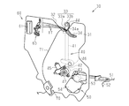
- FIG. 2 is a schematic diagram showing the internal structure of the slide door 10.
- the slide door 10 includes an outer panel 11, an inner panel 12, a vehicle door module 30 attached to the inner panel 12, and a window glass 4.
- An interior panel is attached to the inner side (vehicle inner side) of the inner panel 12.
- the inner panel 12 is attached to the inner side of the outer panel 11.
- the inner panel 12 is provided with an opening 12a in which the vehicle door module 30 is disposed.
- the inner panel 12 has an attachment portion 12c to which a pulley 44 of a window glass elevating device 40 described later is attached on the upper side of the edge portion 12b of the opening portion 12a.
- the attachment portion 12c extends toward the center of the opening 12a.
- the attachment portion 12c is configured in a mountain shape that widens the skirt from the distal end (protruding end) toward the base end when viewed from the vehicle width direction DX.
- the attachment portion 12c is formed in a shape (a bowl shape) that swells outward in a cross-sectional view (see FIG.
- the portion located on the outermost side in the attachment portion 12c is configured as a portion where the pulley 44 is disposed (hereinafter referred to as “center portion 12d”).
- the central portion 12d is provided with a through hole 12e for fixing the rotation shaft of the pulley 44.
- the window glass 4 can be accommodated in a space between the outer panel 11 and an inner member constituted by the inner panel 12 and the vehicle door module 30.
- the first lock device 13 is disposed on the front side of the slide door 10
- the second lock device 14 is disposed on the rear side of the slide door 10
- the third lock device 15 is disposed on the lower portion of the slide door 10.
- the first to third lock devices 13 to 15 are disposed between the outer panel 11 and the inner panel 12.
- the first locking device 13 engages with a striker 16a (see FIG. 1) provided at the front edge of the entrance 3 of the vehicle body 2.
- the second locking device 14 engages with a striker 16b (see FIG. 1) provided at the rear edge of the entrance / exit 3 of the vehicle main body 2.
- the third locking device 15 engages with a striker (not shown) provided at the lower edge portion of the entrance / exit 3 of the vehicle body 2.
- a striker not shown
- the slide door 10 is restrained by the third lock device 15 when it is in the fully open position.
- the movement of the sliding door 10 is restricted by being restrained by the first and second locking devices 13 and 14 or the third locking device 15.
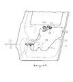
- the vehicle door module 30 will be described with reference to FIG.
- the vehicle door module 30 operates a resin base 31, a window glass elevating device 40 that elevates and lowers the window glass 4, a door moving device 50 that moves the slide door 10, and the first to third lock devices 13 to 15. And a door opening / closing device 60.
- the window glass lifting device 40, the door moving device 50, and the door opening / closing device 60 are attached to the base 31.
- the window glass elevating device 40 includes first and second cables (window glass cables) 41 and 42 that pull the window glass 4, and a drum (window glass drum) 43 that winds the first and second cables 41 and 42. And a pulley 44 that stretches the first and second cables 41, 42 in cooperation with the drum 43, a window glass raising / lowering motor 45 that rotates the drum 43, and a carrier 46 that is attached to the lower end of the window glass 4.
- the drum 43 and the pulley 44 are disposed on the outer surface of the base 31.
- the pulley 44 is disposed above the lower end of the window glass 4 when the window glass 4 is located at the bottom dead center (the lowest point in the moving range of the window glass 4).
- the window glass raising / lowering motor 45 is disposed on the inner surface of the base 31 (the vehicle inner surface in the vehicle width direction DX. The same applies hereinafter).
- the window glass raising / lowering motor 45 and the drum 43 are connected via a speed reducer 47.
- the output shaft of the speed reducer 47 is connected to the drum 43 through a through hole provided in the base 31.
- the first cable 41 is stretched so as to be folded back by a pulley 44.
- the first cable 41 has one end connected to the drum 43 and the other end connected to the carrier 46.
- the second cable 42 is stretched so as to extend in a direction opposite to the first cable 41 with respect to the carrier 46.
- the second cable 42 has one end connected to the carrier 46 and the other end connected to the drum 43.
- the carrier 46 moves with the movement of the first cable 41 and the second cable 42.
- the window glass 4 moves up and down within a predetermined movement range.
- the door moving device 50 includes third and fourth cables (door cables) 51 and 52 that pull the slide door 10, a drum (door drum) 53 around which the third and fourth cables 51 and 52 are wound, and a drum 53. And a door moving motor 54 that rotates the door.
- the drum 53 and the door moving motor 54 are connected via a speed reducer.
- the third cable 51 has one end connected to the vehicle body 2 and the other end connected to the drum 53.
- the fourth cable 52 has one end connected to the vehicle body 2 and the other end connected to the drum 53.
- the winding direction of the third cable 51 around the drum 53 and the winding direction of the fourth cable 52 around the drum 53 are opposite to each other.
- the door opening / closing device 60 includes an inner handle 61 disposed inside the slide door 10 and a transmission mechanism 63 that operates the first to third lock devices 13 to 15 based on various operations.
- An outer handle 62 attached to the outside of the slide door 10 is connected to the door opening / closing device 60.
- the inner handle 61 is rotatably attached to the base 31 of the vehicle door module 30.
- the inner handle 61 protrudes from the interior panel to the inside (seat side) in the vehicle width direction DX.
- closure operation When the inner handle 61 is rotated in the first predetermined direction by a first predetermined operation (hereinafter referred to as “closing operation”), this rotation operation is transmitted to the third locking device 15 by the transmission mechanism 63, and the third The lock device 15 is operated.
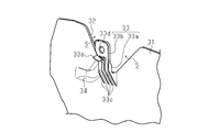
- FIG. 4 is a perspective view of the support portion 33 of the vehicle door module 30 shown in FIG. 3 as viewed from the outside.
- the base 31 is molded from resin.
- the base 31 is formed of a foamed resin. According to the foamed resin, the thickness of the base 31 can be increased as compared with a resin that does not foam, thereby increasing the strength and rigidity of the base 31.
- a waterproof seal is attached to the periphery of the base 31.
- the vehicle door module 30 is attached to the opening 12a of the inner panel 12 so that the waterproof seal is crushed. Thereby, it is suppressed that water permeates from the gap between the peripheral edge of the base 31 and the opening 12a of the inner panel 12.
- the upper edge portion of the base 31 is provided with a portion entering toward the center (hereinafter referred to as a “notch portion 32” because it appears to be formed by notching).
- a support portion 33 that supports the pulley 44 of the window glass lifting device 40 protrudes from the base 31.
- the support portion 33 is aligned with the notch portion 32 as viewed from the vehicle width direction DX.
- the notch 32 is configured so that the mounting portion 12c of the inner panel 12 fits.
- the notch 32 is configured in a V shape when viewed from the vehicle width direction DX.
- the support part 33 has an extension part 33a extending from the edge of the notch part 32 and a part (hereinafter referred to as a pulley arrangement part 33b) provided in the extension part 33a where the pulley 44 of the window glass elevating device 40 is arranged.
- the support portion 33 extends obliquely from the lowermost portion of the notch portion 32 upward and outward in the vehicle width direction DX.
- the pulley arrangement portion 33b is arranged in a different manner from the base 31, in other words, arranged in a shifted manner.
- the support part 33 is comprised, and, thereby, the clearance gap S which spreads in the vehicle width direction DX and the front-back direction DY is comprised in the both sides of the support part 33.
- the support portion 33 is configured such that the pulley arrangement portion 33b is arranged on the outer surface side of the attachment portion 12c when the attachment portion 12c of the inner panel 12 is fitted into the notch portion 32 of the base 31.
- the pulley 44 is arranged outside the pulley arrangement portion 33b in the vehicle width direction DX.
- a reinforcing portion for reinforcing the extending portion 33a is provided on the outer surface of the extending portion 33a.
- the reinforcing portion is, for example, a plurality of ribs 33 c that are integrally formed with the support portion 33.
- the rib 33 c extends to the base 31. That is, the rib 33 c has one end connected to the base 31 and the other end extending to the tip of the extension portion 33 a of the support portion 33.
- the pulley arrangement portion 33 b is provided with a through hole 33 d for supporting the rotation shaft of the pulley 44.
- a wall 33e surrounding the pulley 44 is provided in the pulley arrangement portion 33b.
- the window glass elevating device 40 is arranged on the base 31 as follows (see FIG. 3). That is, the window glass raising / lowering motor 45 and the speed reducer 47 are arranged on the inner surface of the center lower portion of the base 31, and the drum 43 of the window glass raising / lowering device 40 is arranged on the outer surface of the base 31.
- a door opening / closing device 60 is disposed on the inner surface of the upper front portion of the base 31.
- the door opening / closing device 60 includes an inner handle 61 and a plurality of levers (transmission mechanism 63). Some of these levers are connected to the first to third locking devices 13 to 15 by a power transmission cable 17.
- These power transmission cables 17 extend from the door opening / closing device 60, pass through the notch portion 32 of the base 31, are handed over to the outer surface side of the base 31, and extend along a guide groove 34 described later.
- the power transmission cable 17 is connected to the first to third lock devices 13 to 15, respectively.
- the base 31 is attached with a power supply module 70 for supplying electric power to each electrical component such as a window glass raising / lowering motor 45.
- the power supply module 70 has a plurality of power supply cables 71. Several of these power supply cables 71 are connected to electrical components arranged on the inner surface side of the base 31, and the remaining power supply cables 71 pass through the notch portions 32 of the base 31 and are handed over to the outer surface side of the base 31. Furthermore, it extends along the guide groove 34 and is connected to an electrical component arranged on the outer surface side of the base 31.
- the notch 32 of the base 31 is provided with a guide groove 34 for guiding the power transmission cable 17 and the power feeding cable 71.
- the guide groove 34 extends from a portion other than the support portion 33 at the edge of the notch portion 32 of the base 31 and is recessed inside the vehicle width direction DX.
- An end portion of the guide groove 34 corresponding to the notch portion 32 is configured as an open end surface including a surface perpendicular to a surface including the notch portion 32 (generally, a plane extending in a direction in which the base 31 expands). . That is, the guide groove 34 has an open end 34a (see FIG. 3) perpendicular to the direction in which the base 31 spreads.
- the power transmission cable 17 and the power feeding cable 71 are arranged so as to pass through the opening end 34a and extend from the inner surface side to the outer surface side of the base 31, the power transmission cable 17 and the power feeding cable 71 are large in the range from the inner surface side to the outer surface side of the base 31. Not bent. Further, since the opening end 34 a of the guide groove 34 is formed at the edge of the notch 32, the power transmission cable 17 and the power supply cable 71 can be obtained simply by hooking the power transmission cable 17 and the power supply cable 71 on the notch 32. Are arranged so as to extend from the inner surface side of the base 31 to the outer surface side. Such an operation is simpler than the operation of inserting the power transmission cable 17 and the power feeding cable 71 into the through hole provided in the base 31.
- the opening end 34a of the guide groove 34 is perpendicular to the direction in which the base 31 spreads (the surface of the base 31), when the vehicle door module 30 is disposed in the opening 12a of the inner panel 12, the power transmission cable 17 and the feeding cable 71 are not sandwiched and pressed between the mounting portion 12c of the inner panel 12 and the base 31. For this reason, it is suppressed that the function of the power transmission cable 17 and the electric power feeding cable 71 is impaired.
- the base 31 is provided with a support portion 33 that supports the pulley 44 of the window glass lifting device 40.
- the support portion 33 is supported by the edge portion 12 b of the opening portion 12 a of the inner panel 12.
- the pulley 44 is fixed to the inner panel 12 via the support portion 33, when the window glass 4 stops at the top dead center or the bottom dead center, the pulley 44 is added to the pulley 44 of the window glass lifting / lowering device 40.
- the impact force can be distributed to the inner panel 12.
- the attachment portion 12c provided on the edge portion 12b of the opening portion 12a of the inner panel 12 to which the pulley 44 is attached extends toward the center of the opening portion 12a.
- the base 31 is provided with a notch 32 into which the mounting portion 12c of the inner panel 12 is fitted.
- the support portion 33 protrudes from the edge of the notch portion 32 so as to be arranged in a step with respect to the base 31.
- the gap S having a width in the vehicle width direction DX is provided between the peripheral portion of the notch portion 32 and the support portion 33 arranged in a step with respect to the base 31.
- the attachment portion 12c of the inner panel 12 is inserted into the cutout portion 32, and the base 31 is disposed in the opening 12a of the inner panel 12.
- the support portion 33 and the attachment portion 12c interfere with each other.
- since there is a gap S between the peripheral portion of the notch 32 and the support portion 33 interference between the support portion 33 and the mounting portion 12c is reduced. Installation is easy.
- the base 31 is provided with the feed cable 71 and the guide groove 34 that guides the power transmission cable 17 arranged on the inner surface side of the base 31 to the outer surface side of the base 31.
- the guide groove 34 is recessed inward in the vehicle width direction DX and has an open end 34 a at the edge of the notch 32.
- the support portion 33 is reinforced by the rib 33c (reinforcement portion). According to this configuration, deterioration of the support portion 33 is suppressed.
- the opening end 34 a of the guide groove 34 is perpendicular to the direction in which the base 31 spreads. For this reason, when the vehicle door module 30 is arrange
- the pulley 44 is arrange
- a waterproof seal is provided on the periphery of the base 31, no waterproof seal is attached around the support portion 33. This is because the support portion 33 protrudes from the edge of the notch portion 32 so that the support portion 33 is disposed so as to overlap the mounting portion 12 c of the inner panel 12. For this reason, when the window glass 4 is wet and accommodated between the inner panel 12 and the outer panel 11, water may leak from the periphery of the support portion 33 to the inside (seat side) of the vehicle door module 30. .
- the pulley 44 and the support portion 33 are wetted by water droplets falling from the lower end of the window glass 4, and this water Enters the inside of the vehicle door module 30 through the support portion 33.
- the configuration in which the pulley 44 is disposed above the lower end of the window glass 4 when the window glass 4 is located at the bottom dead center water drops falling from the lower end of the window glass 4 can be obtained. Since it does not fall on the pulley 44 and the support part 33, intrusion of water in such a path is suppressed.
- the support portion 33 of the base 31 is configured to bisect the space inside the notch portion 32, but the configuration of the support portion 33 is this. It is not limited to.
- the support portion 33 extends so as to intersect the extension direction DA of the attachment portion 12 c when the base 31 is disposed in the opening portion 12 a of the inner panel 12. That is, one of the two gaps SA and SB existing on both sides of the support portion 33 is larger than the other.
- the extension direction DA of the attachment portion 12c indicates a direction in which the attachment portion 12c extends from the lower edge of the window frame.
- the attachment portion 12c substantially extends downward.
- the vehicle door module 30 When the vehicle door module 30 is attached to the inner panel 12, the vehicle door module 30 is brought close to the opening 12a of the inner panel 12 so that the attachment portion 12c is inserted into a gap having a large dimension among the two gaps SA and SB. Specifically, the vehicle door module 30 can be moved along the front-rear direction DY of the inner panel 12, and the support portion 33 can be disposed outside the mounting portion 12 c of the inner panel 12.
- FIG. 7 is a view of the inner panel 12 as viewed from the outside.
- the vehicle door module 30 is attached to the inner panel 12 first, the vehicle door module 30 is disposed in front of the inner panel 12. Then, the vehicle door module 30 is moved rearward. As described above, the attachment portion 12c of the inner panel 12 enters the gap SB between the support portion 33 and the base 31, and the support portion 33 is disposed outside the vehicle width direction DX in the attachment portion 12c.
- the vehicle door module 30 When the two gaps SA and SB on both sides of the support portion 33 are formed to have substantially the same size, the vehicle door module 30 is disposed on the lower side of the inner panel 12 and moved upward from that state.
- the support portion 33 is disposed outside the attachment portion 12c of the inner panel 12.
- the work of lifting the vehicle door module 30 upward is burdensome for the operator. In this regard, according to the above-described configuration, there is no work of lifting the vehicle door module 30 upward, so that the burden is relatively small.
- the cables 51 and 52 drawn from the door moving device 50 are directed to the inner panel 12. That is, the moving direction of the third and fourth cables 51 and 52 matches the pulling direction of the third and fourth cables 51 and 52 with respect to the door moving device 50. Therefore, the third and fourth cables 51 and 52 can be easily inserted through the cable insertion hole 12 f of the inner panel 12. That is, the arrangement of the third and fourth cables 51 and 52 with respect to the inner panel 12 is simple.
- a device different from the device described above can be attached to the base 31 of the vehicle door module 30.
- an acoustic speaker unit or the like can be attached.
- the door opening / closing device 60 is constituted by a plurality of levers, but the structure of the door opening / closing device 60 is not limited to this.
- the structure of the inner handle 61 is not limited to the embodiment.
- the window glass elevating device 40 extends the cables 41 and 42 with one pulley 44 and the drum 43, but the configuration of the window glass elevating device 40 is not limited to this.
- the window glass elevating device 40 may be one in which the cables 41 and 42 are stretched by two pulleys and the drum 43, or the cable 41 and 42 are stretched by four pulleys and the drum 43.
- the present invention is applied to the vehicle door module 30 attached to the slide door 10, but the technology can also be applied to the vehicle door module 30 attached to the swing door.
Abstract
The vehicle door module according to the present invention is provided with: a base attached to an opening of an inner panel; a window glass raising/lowering device attached to the base, the window glass raising/lowering device provided with a window glass cable for pulling a window glass, a window glass drum for winding the window glass cable, a window glass raising/lowering motor for rotating the window glass drum, and at least one pulley for guiding the window glass cable; and a support for supporting the pulley, the support being provided to the base and supported by an edge part of the opening of the inner panel.
Description
本発明は、窓ガラス昇降装置を有する車両ドアモジュールに関する。
The present invention relates to a vehicle door module having a window glass lifting device.
窓ガラス昇降装置として、特許文献1に記載の技術が知られている。特許文献1に記載の技術では、窓ガラス昇降装置はインナーパネルに取り付けられる。
車両ドアの生産効率の向上を目的として、インナーパネル内に実装される各種装置が一体にモジュール化される場合もある。この技術では、車両ドアモジュールのベースに窓ガラス昇降装置が取り付けられる(例えば、特許文献2)。 As a window glass elevating device, a technique described inPatent Document 1 is known. In the technique described in Patent Document 1, the window glass lifting device is attached to the inner panel.
In order to improve the production efficiency of the vehicle door, various devices mounted in the inner panel may be integrated into a module. In this technique, a window glass lifting device is attached to the base of a vehicle door module (for example, Patent Document 2).
車両ドアの生産効率の向上を目的として、インナーパネル内に実装される各種装置が一体にモジュール化される場合もある。この技術では、車両ドアモジュールのベースに窓ガラス昇降装置が取り付けられる(例えば、特許文献2)。 As a window glass elevating device, a technique described in
In order to improve the production efficiency of the vehicle door, various devices mounted in the inner panel may be integrated into a module. In this technique, a window glass lifting device is attached to the base of a vehicle door module (for example, Patent Document 2).
しかし、車両ドアモジュールでは次の課題がある。すなわち、窓ガラスが上死点または下死点で停止するときに窓ガラス昇降装置のプーリに衝撃力が加わり、ベースが変形する。このようなベースの変形は、窓ガラスの上死点または下死点で停止する度に生じるため、ベースの劣化が促進される恐れがある。
However, the vehicle door module has the following problems. That is, when the window glass stops at the top dead center or the bottom dead center, an impact force is applied to the pulley of the window glass lifting device, and the base is deformed. Such deformation of the base occurs every time the window glass stops at the top dead center or the bottom dead center of the window glass, so that the deterioration of the base may be promoted.
本発明の目的は、ベースの劣化を抑制することができる車両ドアモジュールを提供することにある。
An object of the present invention is to provide a vehicle door module that can suppress deterioration of a base.
上記課題を解決する車両ドアモジュールは、インナーパネルの開口部に取り付けられるベースと、前記ベースに取り付けられる窓ガラス昇降装置であって、窓ガラスを牽引する窓ガラス用ケーブルと、前記窓ガラス用ケーブルを巻く窓ガラス用ドラムと、前記窓ガラス用ドラムを回転させる窓ガラス昇降用モータと、前記窓ガラス用ケーブルを案内する少なくとも1個のプーリと、を備える前記窓ガラス昇降装置と、前記ベースに設けられ、前記プーリを支持しかつ前記インナーパネルの前記開口部の縁部に支持される支持部と、を備える。
A vehicle door module that solves the above problems includes a base that is attached to an opening of an inner panel, a window glass lifting device that is attached to the base, a window glass cable that pulls the window glass, and the window glass cable. A window glass drum, a window glass lift motor for rotating the window glass drum, and at least one pulley for guiding the window glass cable; And a support portion that supports the pulley and is supported by an edge of the opening of the inner panel.
図1~図5を参照して、車両ドアモジュール30について説明する。
図1は、車両1の平面図である。図1に示すように、ステアリングホイール1aが車両1の前側に配置されている。以降の説明では、スライドドア10が車両本体2に取り付けられた状態で、車両1の上下方向と一致する方向を車両ドアモジュール30の「上下方向DZ」と規定する。車両1の前後方向と一致する方向を車両ドアモジュール30の「前後方向DY」と規定する。車両1の車幅方向と一致する方向を車両ドアモジュール30の「車幅方向DX」と規定する。 Thevehicle door module 30 will be described with reference to FIGS.
FIG. 1 is a plan view of thevehicle 1. As shown in FIG. 1, a steering wheel 1 a is disposed on the front side of the vehicle 1. In the following description, the direction that coincides with the vertical direction of the vehicle 1 with the slide door 10 attached to the vehicle body 2 is defined as the “vertical direction DZ” of the vehicle door module 30. A direction that coincides with the front-rear direction of the vehicle 1 is defined as the “front-rear direction DY” of the vehicle door module 30. A direction coinciding with the vehicle width direction of the vehicle 1 is defined as the “vehicle width direction DX” of the vehicle door module 30.
図1は、車両1の平面図である。図1に示すように、ステアリングホイール1aが車両1の前側に配置されている。以降の説明では、スライドドア10が車両本体2に取り付けられた状態で、車両1の上下方向と一致する方向を車両ドアモジュール30の「上下方向DZ」と規定する。車両1の前後方向と一致する方向を車両ドアモジュール30の「前後方向DY」と規定する。車両1の車幅方向と一致する方向を車両ドアモジュール30の「車幅方向DX」と規定する。 The
FIG. 1 is a plan view of the
スライドドア10は、車両本体2の乗降口3に取り付けられる。
スライドドア10は、乗降口3を閉鎖する全閉位置から、乗降口3を全開する全開位置までの範囲で、車両本体2に敷設されたドアレールに沿って移動する。スライドドア10は、全閉位置から車幅方向DXに移動可能に、かつ全閉位置から外側に移動した状態で前後方向DYに移動可能に、車両本体2に取り付けられている。 The slidingdoor 10 is attached to the entrance / exit 3 of the vehicle body 2.
Theslide door 10 moves along a door rail laid on the vehicle body 2 in a range from a fully closed position where the entrance / exit 3 is closed to a fully open position where the entrance / exit 3 is fully opened. The slide door 10 is attached to the vehicle main body 2 so as to be movable in the vehicle width direction DX from the fully closed position and to be movable in the front-rear direction DY while being moved outward from the fully closed position.
スライドドア10は、乗降口3を閉鎖する全閉位置から、乗降口3を全開する全開位置までの範囲で、車両本体2に敷設されたドアレールに沿って移動する。スライドドア10は、全閉位置から車幅方向DXに移動可能に、かつ全閉位置から外側に移動した状態で前後方向DYに移動可能に、車両本体2に取り付けられている。 The sliding
The
図2は、スライドドア10の内部構造を示す模式図である。
スライドドア10は、アウターパネル11と、インナーパネル12と、インナーパネル12に取り付けられる車両ドアモジュール30と、窓ガラス4とを備えている。インナーパネル12の内側(車内側)には内装パネルが取り付けられる。 FIG. 2 is a schematic diagram showing the internal structure of theslide door 10.
Theslide door 10 includes an outer panel 11, an inner panel 12, a vehicle door module 30 attached to the inner panel 12, and a window glass 4. An interior panel is attached to the inner side (vehicle inner side) of the inner panel 12.
スライドドア10は、アウターパネル11と、インナーパネル12と、インナーパネル12に取り付けられる車両ドアモジュール30と、窓ガラス4とを備えている。インナーパネル12の内側(車内側)には内装パネルが取り付けられる。 FIG. 2 is a schematic diagram showing the internal structure of the
The
インナーパネル12は、アウターパネル11の内側に取り付けられる。インナーパネル12には、車両ドアモジュール30が配置される開口部12aが設けられている。インナーパネル12は、開口部12aの縁部12bの上辺に、後述の窓ガラス昇降装置40のプーリ44が取り付けられる取付部12cを有する。取付部12cは、開口部12aの中央に向けて延びる。取付部12cは、車幅方向DXからみて、先端(突出端)から基端に向かって裾野を広げる山形に構成されている。取付部12cは、前後方向DYからみた断面視(図5参照)で、外側に膨らむ形状(ボウル型)に形成されている。この構成により、取付部12cの曲げ強度が高められている。取付部12cにおいて最も外側に位置する部分は、プーリ44が配置される部分(以下、「中央部12d」という。)として構成されている。この中央部12dには、プーリ44の回転軸を固定するための貫通孔12eが設けられている。
The inner panel 12 is attached to the inner side of the outer panel 11. The inner panel 12 is provided with an opening 12a in which the vehicle door module 30 is disposed. The inner panel 12 has an attachment portion 12c to which a pulley 44 of a window glass elevating device 40 described later is attached on the upper side of the edge portion 12b of the opening portion 12a. The attachment portion 12c extends toward the center of the opening 12a. The attachment portion 12c is configured in a mountain shape that widens the skirt from the distal end (protruding end) toward the base end when viewed from the vehicle width direction DX. The attachment portion 12c is formed in a shape (a bowl shape) that swells outward in a cross-sectional view (see FIG. 5) viewed from the front-rear direction DY. With this configuration, the bending strength of the attachment portion 12c is increased. The portion located on the outermost side in the attachment portion 12c is configured as a portion where the pulley 44 is disposed (hereinafter referred to as “center portion 12d”). The central portion 12d is provided with a through hole 12e for fixing the rotation shaft of the pulley 44.
窓ガラス4は、インナーパネル12及び車両ドアモジュール30により構成されるインナー部材と、アウターパネル11との間の空間に収容され得る。
第1ロック装置13がスライドドア10の前側に配置され、第2ロック装置14がスライドドア10の後側に配置され、第3ロック装置15がスライドドア10の下部に配置される。第1~第3ロック装置13~15は、アウターパネル11とインナーパネル12との間に配置される。 The window glass 4 can be accommodated in a space between theouter panel 11 and an inner member constituted by the inner panel 12 and the vehicle door module 30.
Thefirst lock device 13 is disposed on the front side of the slide door 10, the second lock device 14 is disposed on the rear side of the slide door 10, and the third lock device 15 is disposed on the lower portion of the slide door 10. The first to third lock devices 13 to 15 are disposed between the outer panel 11 and the inner panel 12.
第1ロック装置13がスライドドア10の前側に配置され、第2ロック装置14がスライドドア10の後側に配置され、第3ロック装置15がスライドドア10の下部に配置される。第1~第3ロック装置13~15は、アウターパネル11とインナーパネル12との間に配置される。 The window glass 4 can be accommodated in a space between the
The
第1ロック装置13は、車両本体2の乗降口3の前縁部に設けられたストライカ16a(図1参照)に係合する。
第2ロック装置14は、車両本体2の乗降口3の後縁部に設けられたストライカ16b(図1参照)に係合する。 Thefirst locking device 13 engages with a striker 16a (see FIG. 1) provided at the front edge of the entrance 3 of the vehicle body 2.
Thesecond locking device 14 engages with a striker 16b (see FIG. 1) provided at the rear edge of the entrance / exit 3 of the vehicle main body 2.
第2ロック装置14は、車両本体2の乗降口3の後縁部に設けられたストライカ16b(図1参照)に係合する。 The
The
第3ロック装置15は、車両本体2の乗降口3の下縁部に設けられたストライカ(図示省略)に係合する。
スライドドア10は、全閉位置に位置するとき、第1及び第2ロック装置13,14に拘束される。スライドドア10は、全開位置に位置するとき、第3ロック装置15に拘束される。スライドドア10は、第1及び第2ロック装置13,14または第3ロック装置15により拘束されることによりその移動が制限される。 Thethird locking device 15 engages with a striker (not shown) provided at the lower edge portion of the entrance / exit 3 of the vehicle body 2.
When the slidingdoor 10 is located at the fully closed position, the sliding door 10 is restrained by the first and second locking devices 13 and 14. The slide door 10 is restrained by the third lock device 15 when it is in the fully open position. The movement of the sliding door 10 is restricted by being restrained by the first and second locking devices 13 and 14 or the third locking device 15.
スライドドア10は、全閉位置に位置するとき、第1及び第2ロック装置13,14に拘束される。スライドドア10は、全開位置に位置するとき、第3ロック装置15に拘束される。スライドドア10は、第1及び第2ロック装置13,14または第3ロック装置15により拘束されることによりその移動が制限される。 The
When the sliding
図3を参照して、車両ドアモジュール30について説明する。
車両ドアモジュール30は、樹脂製のベース31と、窓ガラス4を昇降させる窓ガラス昇降装置40と、スライドドア10を移動させるドア移動装置50と、第1~第3ロック装置13~15を操作するドア開閉装置60とを備える。窓ガラス昇降装置40、ドア移動装置50及びドア開閉装置60はベース31に取り付けられている。 Thevehicle door module 30 will be described with reference to FIG.
Thevehicle door module 30 operates a resin base 31, a window glass elevating device 40 that elevates and lowers the window glass 4, a door moving device 50 that moves the slide door 10, and the first to third lock devices 13 to 15. And a door opening / closing device 60. The window glass lifting device 40, the door moving device 50, and the door opening / closing device 60 are attached to the base 31.
車両ドアモジュール30は、樹脂製のベース31と、窓ガラス4を昇降させる窓ガラス昇降装置40と、スライドドア10を移動させるドア移動装置50と、第1~第3ロック装置13~15を操作するドア開閉装置60とを備える。窓ガラス昇降装置40、ドア移動装置50及びドア開閉装置60はベース31に取り付けられている。 The
The
窓ガラス昇降装置40は、窓ガラス4を牽引する第1及び第2ケーブル(窓ガラス用ケーブル)41,42と、第1及び第2ケーブル41,42を巻くドラム(窓ガラス用ドラム)43と、ドラム43と協働して第1及び第2ケーブル41,42を張るプーリ44と、ドラム43を回転させる窓ガラス昇降用モータ45と、窓ガラス4の下端に取り付けられるキャリア46とを備える。
The window glass elevating device 40 includes first and second cables (window glass cables) 41 and 42 that pull the window glass 4, and a drum (window glass drum) 43 that winds the first and second cables 41 and 42. And a pulley 44 that stretches the first and second cables 41, 42 in cooperation with the drum 43, a window glass raising / lowering motor 45 that rotates the drum 43, and a carrier 46 that is attached to the lower end of the window glass 4.
ドラム43及びプーリ44は、ベース31の外面に配置される。プーリ44は、窓ガラス4が下死点(窓ガラス4の移動範囲における最下点)に位置するときの窓ガラス4の下端よりも上方に配置される。窓ガラス昇降用モータ45は、ベース31の内面(車幅方向DXにおける車内側の面。以下、同じ。)に配置される。窓ガラス昇降用モータ45とドラム43とは減速機47を介して接続される。減速機47の出力軸は、ベース31に設けられた貫通孔を挿通して、ドラム43に接続される。
The drum 43 and the pulley 44 are disposed on the outer surface of the base 31. The pulley 44 is disposed above the lower end of the window glass 4 when the window glass 4 is located at the bottom dead center (the lowest point in the moving range of the window glass 4). The window glass raising / lowering motor 45 is disposed on the inner surface of the base 31 (the vehicle inner surface in the vehicle width direction DX. The same applies hereinafter). The window glass raising / lowering motor 45 and the drum 43 are connected via a speed reducer 47. The output shaft of the speed reducer 47 is connected to the drum 43 through a through hole provided in the base 31.
第1ケーブル41はプーリ44で折り返されるように張られる。第1ケーブル41は、ドラム43に接続される一端と、キャリア46に接続される他端とを有する。
第2ケーブル42は、キャリア46に対して第1ケーブル41とは反対方向に延びるように張られる。第2ケーブル42は、キャリア46に接続される一端と、ドラム43に接続される他端とを有する。 Thefirst cable 41 is stretched so as to be folded back by a pulley 44. The first cable 41 has one end connected to the drum 43 and the other end connected to the carrier 46.
Thesecond cable 42 is stretched so as to extend in a direction opposite to the first cable 41 with respect to the carrier 46. The second cable 42 has one end connected to the carrier 46 and the other end connected to the drum 43.
第2ケーブル42は、キャリア46に対して第1ケーブル41とは反対方向に延びるように張られる。第2ケーブル42は、キャリア46に接続される一端と、ドラム43に接続される他端とを有する。 The
The
ドラム43の回転により第1ケーブル41または第2ケーブル42がドラム43に巻かれると、第1ケーブル41及び第2ケーブル42の移動に伴ってキャリア46が移動する。これにより、窓ガラス4が所定移動範囲内で昇降する。
When the first cable 41 or the second cable 42 is wound around the drum 43 by the rotation of the drum 43, the carrier 46 moves with the movement of the first cable 41 and the second cable 42. Thereby, the window glass 4 moves up and down within a predetermined movement range.
ドア移動装置50は、スライドドア10を牽引する第3及び第4ケーブル(ドア用ケーブル)51,52と、第3及び第4ケーブル51,52を巻くドラム(ドア用ドラム)53と、ドラム53を回転させるドア移動用モータ54とを備える。ドラム53とドア移動用モータ54とは減速機を介して接続されている。
The door moving device 50 includes third and fourth cables (door cables) 51 and 52 that pull the slide door 10, a drum (door drum) 53 around which the third and fourth cables 51 and 52 are wound, and a drum 53. And a door moving motor 54 that rotates the door. The drum 53 and the door moving motor 54 are connected via a speed reducer.
第3ケーブル51は、車両本体2に接続される一端と、ドラム53に接続される他端とを有する。第4ケーブル52は、車両本体2に接続される一端と、ドラム53に接続される他端とを有する。第3ケーブル51のドラム53に対する巻き方向と第4ケーブル52のドラム53に対する巻き方向とは互いに逆である。ドラム53の回転により第3ケーブル51または第4ケーブル52がドラム53に巻かれると、スライドドア10が移動する。
The third cable 51 has one end connected to the vehicle body 2 and the other end connected to the drum 53. The fourth cable 52 has one end connected to the vehicle body 2 and the other end connected to the drum 53. The winding direction of the third cable 51 around the drum 53 and the winding direction of the fourth cable 52 around the drum 53 are opposite to each other. When the third cable 51 or the fourth cable 52 is wound around the drum 53 by the rotation of the drum 53, the slide door 10 moves.
ドア開閉装置60は、スライドドア10の内側に配置されるインナーハンドル61と、各種の動作に基づいて第1~第3ロック装置13~15を動作させる伝達機構63とを備える。スライドドア10の外側に取り付けられるアウターハンドル62は、ドア開閉装置60に接続される。
The door opening / closing device 60 includes an inner handle 61 disposed inside the slide door 10 and a transmission mechanism 63 that operates the first to third lock devices 13 to 15 based on various operations. An outer handle 62 attached to the outside of the slide door 10 is connected to the door opening / closing device 60.
インナーハンドル61は、回転可能に車両ドアモジュール30のベース31に取り付けられている。インナーハンドル61は、内装パネルから車幅方向DXの内側(座席側)に突出する。
The inner handle 61 is rotatably attached to the base 31 of the vehicle door module 30. The inner handle 61 protrudes from the interior panel to the inside (seat side) in the vehicle width direction DX.
第1の所定操作(以下、「閉操作」という。)によりインナーハンドル61が第1の所定方向に回転するとき、この回転動作が伝達機構63によって第3ロック装置15に伝達されて、第3ロック装置15が操作される。
When the inner handle 61 is rotated in the first predetermined direction by a first predetermined operation (hereinafter referred to as “closing operation”), this rotation operation is transmitted to the third locking device 15 by the transmission mechanism 63, and the third The lock device 15 is operated.
第2の所定操作(以下、「開操作」という。)によりインナーハンドル61が第2の所定方向に回転するとき、この回転動作が伝達機構63によって第1及び第2ロック装置13,14それぞれに伝達されて第1及び第2ロック装置13,14が操作される。
When the inner handle 61 is rotated in the second predetermined direction by a second predetermined operation (hereinafter referred to as “opening operation”), this rotation operation is applied to each of the first and second lock devices 13 and 14 by the transmission mechanism 63. The first and second lock devices 13 and 14 are operated by being transmitted.
所定操作によりアウターハンドル62が所定方向に回転するとき、この回転動作が伝達機構63によって第1~第3ロック装置13~15に伝達されて、伝達された動力により第1~第3ロック装置13~15が操作される。
When the outer handle 62 is rotated in a predetermined direction by a predetermined operation, the rotation operation is transmitted to the first to third lock devices 13 to 15 by the transmission mechanism 63, and the first to third lock devices 13 are transmitted by the transmitted power. ~ 15 are operated.
図3及び図4を参照して、ベース31の構造及び各装置の配置について説明する。図4は、図3に示す車両ドアモジュール30の支持部33を外側から見た斜視図である。
ベース31は樹脂で成形される。例えば、ベース31は、発泡樹脂により形成される。発泡樹脂によれば、発泡しない樹脂に比べて、ベース31の厚みを増すことができ、これによりベース31の強度及び剛性が高まる。 With reference to FIG.3 and FIG.4, the structure of thebase 31 and arrangement | positioning of each apparatus are demonstrated. FIG. 4 is a perspective view of the support portion 33 of the vehicle door module 30 shown in FIG. 3 as viewed from the outside.
Thebase 31 is molded from resin. For example, the base 31 is formed of a foamed resin. According to the foamed resin, the thickness of the base 31 can be increased as compared with a resin that does not foam, thereby increasing the strength and rigidity of the base 31.
ベース31は樹脂で成形される。例えば、ベース31は、発泡樹脂により形成される。発泡樹脂によれば、発泡しない樹脂に比べて、ベース31の厚みを増すことができ、これによりベース31の強度及び剛性が高まる。 With reference to FIG.3 and FIG.4, the structure of the
The
ベース31の周縁には、防水用シールが貼り付けられている。車両ドアモジュール30は、防水用シールが押し潰されるように、インナーパネル12の開口部12aに取り付けられる。これにより、ベース31の周縁とインナーパネル12の開口部12aとの間の隙間から水が浸入することが抑制される。
A waterproof seal is attached to the periphery of the base 31. The vehicle door module 30 is attached to the opening 12a of the inner panel 12 so that the waterproof seal is crushed. Thereby, it is suppressed that water permeates from the gap between the peripheral edge of the base 31 and the opening 12a of the inner panel 12.
ベース31の上縁部には、中央に向かって入り込む部分(切り欠いて形成されたように見えるため、以下では「切欠き部32」という。)が設けられている。窓ガラス昇降装置40のプーリ44を支持する支持部33が、ベース31から突出している。車幅方向DXから見て、支持部33は切欠き部32と位置的に整合する。切欠き部32は、インナーパネル12の取付部12cが嵌るように構成されている。例えば、切欠き部32は、車幅方向DXからみてV字形状に構成される。
The upper edge portion of the base 31 is provided with a portion entering toward the center (hereinafter referred to as a “notch portion 32” because it appears to be formed by notching). A support portion 33 that supports the pulley 44 of the window glass lifting device 40 protrudes from the base 31. The support portion 33 is aligned with the notch portion 32 as viewed from the vehicle width direction DX. The notch 32 is configured so that the mounting portion 12c of the inner panel 12 fits. For example, the notch 32 is configured in a V shape when viewed from the vehicle width direction DX.
支持部33は、切欠き部32の縁から延びる延長部33aと、延長部33aに設けられて窓ガラス昇降装置40のプーリ44が配置される部分(以下、プーリ配置部33b)とを有する。
The support part 33 has an extension part 33a extending from the edge of the notch part 32 and a part (hereinafter referred to as a pulley arrangement part 33b) provided in the extension part 33a where the pulley 44 of the window glass elevating device 40 is arranged.
図4及び図5に示されるように、支持部33は、切欠き部32の最下部から上方向かつ車幅方向DX外側に向かって斜めに延びる。すなわち、車幅方向DX(ベース31の厚さ方向、或いはベース31の面と直交する方向)において、プーリ配置部33bがベース31と段違いに配置されるように、言い換えれば、ずれて配置されるように、支持部33が構成され、これにより、支持部33の両側に車幅方向DX及び前後方向DYに広がる隙間Sが構成される。
As shown in FIGS. 4 and 5, the support portion 33 extends obliquely from the lowermost portion of the notch portion 32 upward and outward in the vehicle width direction DX. In other words, in the vehicle width direction DX (the thickness direction of the base 31 or the direction orthogonal to the surface of the base 31), the pulley arrangement portion 33b is arranged in a different manner from the base 31, in other words, arranged in a shifted manner. Thus, the support part 33 is comprised, and, thereby, the clearance gap S which spreads in the vehicle width direction DX and the front-back direction DY is comprised in the both sides of the support part 33. FIG.
ベース31の切欠き部32にインナーパネル12の取付部12cが嵌ったときにプーリ配置部33bが取付部12cの外面側に配置されるように、支持部33が構成されている。プーリ44は、プーリ配置部33bの車幅方向DX外側に配置される。
The support portion 33 is configured such that the pulley arrangement portion 33b is arranged on the outer surface side of the attachment portion 12c when the attachment portion 12c of the inner panel 12 is fitted into the notch portion 32 of the base 31. The pulley 44 is arranged outside the pulley arrangement portion 33b in the vehicle width direction DX.
図4に示されるように、延長部33aの外面には、延長部33aを補強するための補強部が設けられている。補強部は、例えば、支持部33と一体成形される複数本のリブ33cである。リブ33cはベース31にまで延長する。すなわち、リブ33cは、ベース31に接続される一端と、支持部33の延長部33aの先端部まで延びる他端とを有する。プーリ配置部33bには、プーリ44の回転軸を支持するための貫通孔33dが設けられている。プーリ配置部33bには、プーリ44を囲む壁33eが設けられている。
As shown in FIG. 4, a reinforcing portion for reinforcing the extending portion 33a is provided on the outer surface of the extending portion 33a. The reinforcing portion is, for example, a plurality of ribs 33 c that are integrally formed with the support portion 33. The rib 33 c extends to the base 31. That is, the rib 33 c has one end connected to the base 31 and the other end extending to the tip of the extension portion 33 a of the support portion 33. The pulley arrangement portion 33 b is provided with a through hole 33 d for supporting the rotation shaft of the pulley 44. A wall 33e surrounding the pulley 44 is provided in the pulley arrangement portion 33b.
窓ガラス昇降装置40は次のようにベース31に配置される(図3参照)。すなわち、ベース31の中央下部における内面に、窓ガラス昇降用モータ45及び減速機47が配置され、ベース31の外面には、窓ガラス昇降装置40のドラム43が配置される。
The window glass elevating device 40 is arranged on the base 31 as follows (see FIG. 3). That is, the window glass raising / lowering motor 45 and the speed reducer 47 are arranged on the inner surface of the center lower portion of the base 31, and the drum 43 of the window glass raising / lowering device 40 is arranged on the outer surface of the base 31.
ベース31の上方前部の内面には、ドア開閉装置60が配置される。ドア開閉装置60は、インナーハンドル61と複数個のレバー(伝達機構63)とを備える。このうちの幾つかのレバーは、動力伝達ケーブル17によって上記第1~第3ロック装置13~15に接続されている。これら動力伝達ケーブル17は、ドア開閉装置60から延びてベース31の切欠き部32を通過してベース31の外面側に引き渡されて後述の案内溝34に沿うように延ばされる。動力伝達ケーブル17は第1~第3ロック装置13~15にそれぞれ接続される。
A door opening / closing device 60 is disposed on the inner surface of the upper front portion of the base 31. The door opening / closing device 60 includes an inner handle 61 and a plurality of levers (transmission mechanism 63). Some of these levers are connected to the first to third locking devices 13 to 15 by a power transmission cable 17. These power transmission cables 17 extend from the door opening / closing device 60, pass through the notch portion 32 of the base 31, are handed over to the outer surface side of the base 31, and extend along a guide groove 34 described later. The power transmission cable 17 is connected to the first to third lock devices 13 to 15, respectively.
ベース31には、窓ガラス昇降用モータ45等の各電装品に電力を供給するための給電モジュール70が取り付けられる。給電モジュール70は、複数本の給電ケーブル71を有する。このうちの数本の給電ケーブル71はベース31の内面側に配置されている電装品に接続され、残りの給電ケーブル71はベース31の切欠き部32を通過してベース31の外面側に引き渡され更に案内溝34に沿うように延ばされて、ベース31の外面側に配置される電装品に接続される。
The base 31 is attached with a power supply module 70 for supplying electric power to each electrical component such as a window glass raising / lowering motor 45. The power supply module 70 has a plurality of power supply cables 71. Several of these power supply cables 71 are connected to electrical components arranged on the inner surface side of the base 31, and the remaining power supply cables 71 pass through the notch portions 32 of the base 31 and are handed over to the outer surface side of the base 31. Furthermore, it extends along the guide groove 34 and is connected to an electrical component arranged on the outer surface side of the base 31.
図4に示されるように、ベース31の切欠き部32には、動力伝達ケーブル17及び給電ケーブル71を案内する案内溝34が設けられている。案内溝34は、ベース31の切欠き部32の縁において支持部33以外の部分から延び、かつ車幅方向DXの内側に窪む。案内溝34における切欠き部32に対応する側の端部は、切欠き部32を含む面(概ね、ベース31が広がる方向に延びる平面)に対して垂直な面を含む開口端面として構成される。すなわち、案内溝34は、ベース31が広がる方向に対して垂直な開口端34a(図3参照)を有する。動力伝達ケーブル17及び給電ケーブル71は、このような開口端34aを通過してベース31の内面側から外面側に渡るように配置されるため、ベース31の内面側から外面側に渡る範囲において大きく屈曲されない。更に、案内溝34の開口端34aが切欠き部32の縁に形成されていることにより、動力伝達ケーブル17及び給電ケーブル71を切欠き部32に掛けるだけで、動力伝達ケーブル17及び給電ケーブル71は、ベース31の内面側から外面側に渡るように配置される。このような作業は、ベース31に設けた貫通孔に動力伝達ケーブル17及び給電ケーブル71を挿通する作業に比べて、簡単である。
As shown in FIG. 4, the notch 32 of the base 31 is provided with a guide groove 34 for guiding the power transmission cable 17 and the power feeding cable 71. The guide groove 34 extends from a portion other than the support portion 33 at the edge of the notch portion 32 of the base 31 and is recessed inside the vehicle width direction DX. An end portion of the guide groove 34 corresponding to the notch portion 32 is configured as an open end surface including a surface perpendicular to a surface including the notch portion 32 (generally, a plane extending in a direction in which the base 31 expands). . That is, the guide groove 34 has an open end 34a (see FIG. 3) perpendicular to the direction in which the base 31 spreads. Since the power transmission cable 17 and the power feeding cable 71 are arranged so as to pass through the opening end 34a and extend from the inner surface side to the outer surface side of the base 31, the power transmission cable 17 and the power feeding cable 71 are large in the range from the inner surface side to the outer surface side of the base 31. Not bent. Further, since the opening end 34 a of the guide groove 34 is formed at the edge of the notch 32, the power transmission cable 17 and the power supply cable 71 can be obtained simply by hooking the power transmission cable 17 and the power supply cable 71 on the notch 32. Are arranged so as to extend from the inner surface side of the base 31 to the outer surface side. Such an operation is simpler than the operation of inserting the power transmission cable 17 and the power feeding cable 71 into the through hole provided in the base 31.
案内溝34の開口端34aは、ベース31が広がる方向(ベース31の面)に対して垂直であるため、車両ドアモジュール30がインナーパネル12の開口部12aに配置されたときに、動力伝達ケーブル17及び給電ケーブル71が、インナーパネル12の取付部12cとベース31とによって挟まれて押圧されるようなことがない。このため、動力伝達ケーブル17及び給電ケーブル71の機能が損なわれることが抑制される。
Since the opening end 34a of the guide groove 34 is perpendicular to the direction in which the base 31 spreads (the surface of the base 31), when the vehicle door module 30 is disposed in the opening 12a of the inner panel 12, the power transmission cable 17 and the feeding cable 71 are not sandwiched and pressed between the mounting portion 12c of the inner panel 12 and the base 31. For this reason, it is suppressed that the function of the power transmission cable 17 and the electric power feeding cable 71 is impaired.
次に、本実施形態に係る車両ドアモジュール30の効果を説明する。
(1)本実施形態では、ベース31には、窓ガラス昇降装置40のプーリ44を支持する支持部33が設けられている。支持部33は、インナーパネル12の開口部12aの縁部12bに支持される。 Next, effects of thevehicle door module 30 according to the present embodiment will be described.
(1) In this embodiment, thebase 31 is provided with a support portion 33 that supports the pulley 44 of the window glass lifting device 40. The support portion 33 is supported by the edge portion 12 b of the opening portion 12 a of the inner panel 12.
(1)本実施形態では、ベース31には、窓ガラス昇降装置40のプーリ44を支持する支持部33が設けられている。支持部33は、インナーパネル12の開口部12aの縁部12bに支持される。 Next, effects of the
(1) In this embodiment, the
この構成によれば、プーリ44が支持部33を介してインナーパネル12に固定されるため、窓ガラス4が上死点または下死点で停止するときに窓ガラス昇降装置40のプーリ44に加わる衝撃力をインナーパネル12に分散させることができる。これにより、ベース31及び支持部33に加わる衝撃力が低下するため、ベース31の劣化が抑制される。
According to this configuration, since the pulley 44 is fixed to the inner panel 12 via the support portion 33, when the window glass 4 stops at the top dead center or the bottom dead center, the pulley 44 is added to the pulley 44 of the window glass lifting / lowering device 40. The impact force can be distributed to the inner panel 12. Thereby, since the impact force added to the base 31 and the support part 33 falls, deterioration of the base 31 is suppressed.
(2)上記実施形態では、インナーパネル12の開口部12aの縁部12bに設けられてプーリ44が取り付けられる取付部12cは、開口部12aの中央に向かって延びる。ベース31には、インナーパネル12の取付部12cが嵌る切欠き部32が設けられている。支持部33は、ベース31に対して段違いに配置されるように、切欠き部32の縁から突出する。インナーパネル12の取付部12cとベース31の切欠き部32とが嵌合するように当該ベース31がインナーパネル12の開口部12aに配置されたときに、支持部33のプーリ配置部33bが取付部12cと位置的に整合するように配置される。
(2) In the above embodiment, the attachment portion 12c provided on the edge portion 12b of the opening portion 12a of the inner panel 12 to which the pulley 44 is attached extends toward the center of the opening portion 12a. The base 31 is provided with a notch 32 into which the mounting portion 12c of the inner panel 12 is fitted. The support portion 33 protrudes from the edge of the notch portion 32 so as to be arranged in a step with respect to the base 31. When the base 31 is disposed in the opening 12a of the inner panel 12 so that the mounting portion 12c of the inner panel 12 and the cutout portion 32 of the base 31 are fitted, the pulley arrangement portion 33b of the support portion 33 is attached. It arrange | positions so that it may align in position with the part 12c.
この構成によれば、切欠き部32の周辺部と、ベース31に対して段違いに配置された支持部33との間に、車幅方向DXに幅のある隙間Sが設けられる。
車両ドアモジュール30をインナーパネル12に取り付けるとき、インナーパネル12の取付部12cを切欠き部32に挿入してベース31をインナーパネル12の開口部12aに配置する。インナーパネル12のこのような取り付けに際して、支持部33と取付部12cとが互いに干渉し合う。この点、上記構成によれば、切欠き部32の周辺部と支持部33との間に隙間Sがあることにより支持部33と取付部12cとの干渉が少なくなるため、車両ドアモジュール30の取り付けが容易となる。 According to this configuration, the gap S having a width in the vehicle width direction DX is provided between the peripheral portion of thenotch portion 32 and the support portion 33 arranged in a step with respect to the base 31.
When thevehicle door module 30 is attached to the inner panel 12, the attachment portion 12c of the inner panel 12 is inserted into the cutout portion 32, and the base 31 is disposed in the opening 12a of the inner panel 12. When such an attachment of the inner panel 12 is performed, the support portion 33 and the attachment portion 12c interfere with each other. In this regard, according to the above configuration, since there is a gap S between the peripheral portion of the notch 32 and the support portion 33, interference between the support portion 33 and the mounting portion 12c is reduced. Installation is easy.
車両ドアモジュール30をインナーパネル12に取り付けるとき、インナーパネル12の取付部12cを切欠き部32に挿入してベース31をインナーパネル12の開口部12aに配置する。インナーパネル12のこのような取り付けに際して、支持部33と取付部12cとが互いに干渉し合う。この点、上記構成によれば、切欠き部32の周辺部と支持部33との間に隙間Sがあることにより支持部33と取付部12cとの干渉が少なくなるため、車両ドアモジュール30の取り付けが容易となる。 According to this configuration, the gap S having a width in the vehicle width direction DX is provided between the peripheral portion of the
When the
(3)上記実施形態では、ベース31には、ベース31の内面側に配置される給電ケーブル71及び動力伝達ケーブル17をベース31の外面側に案内する案内溝34が設けられている。案内溝34は、車幅方向DXにおいて内方に窪みかつ切欠き部32の縁に開口端34aを有する。
(3) In the above embodiment, the base 31 is provided with the feed cable 71 and the guide groove 34 that guides the power transmission cable 17 arranged on the inner surface side of the base 31 to the outer surface side of the base 31. The guide groove 34 is recessed inward in the vehicle width direction DX and has an open end 34 a at the edge of the notch 32.
給電ケーブル71及び動力伝達ケーブル17等のケーブルをベース31の内面側から外面側に渡るように配置する手段として、例えば、ベース31に貫通孔を設ける方法もある。この場合、ケーブル17,71を貫通孔に挿通させる必要があり、手間を要する。この点、上記構成では、ケーブル17,71を案内する案内溝34がベース31の切欠き部32に設けられているため、ケーブル17,71を切欠き部32に掛けるようにするだけで、ケーブル17,71をベース31の内面側から外面側に渡るように配置することができる。このため、ケーブル17,71の取付作業が容易になる。
As a means for arranging cables such as the power supply cable 71 and the power transmission cable 17 from the inner surface side to the outer surface side of the base 31, for example, there is a method of providing a through hole in the base 31. In this case, it is necessary to insert the cables 17 and 71 through the through holes, which is troublesome. In this respect, in the above configuration, since the guide groove 34 for guiding the cables 17 and 71 is provided in the notch 32 of the base 31, the cable 17 and 71 can be simply hooked on the notch 32. 17 and 71 can be arranged so as to extend from the inner surface side of the base 31 to the outer surface side. For this reason, the installation work of the cables 17 and 71 becomes easy.
(4)上記実施形態では、支持部33はリブ33c(補強部)により補強されている。この構成によれば、支持部33の劣化が抑制される。
(5)上記実施形態では、案内溝34の開口端34aは、ベース31が広がる方向に対して垂直である。このため、車両ドアモジュール30がインナーパネル12の開口部12aに配置されたときに、動力伝達ケーブル17及び給電ケーブル71が、インナーパネル12の取付部12cとベース31とによって挟まれることがないため、動力伝達ケーブル17及び給電ケーブル71の機能が損なわれることが抑制される。 (4) In the above embodiment, thesupport portion 33 is reinforced by the rib 33c (reinforcement portion). According to this configuration, deterioration of the support portion 33 is suppressed.
(5) In the above embodiment, the opening end 34 a of theguide groove 34 is perpendicular to the direction in which the base 31 spreads. For this reason, when the vehicle door module 30 is arrange | positioned at the opening part 12a of the inner panel 12, the power transmission cable 17 and the electric power feeding cable 71 are not pinched by the attaching part 12c and the base 31 of the inner panel 12. It is suppressed that the functions of the power transmission cable 17 and the power supply cable 71 are impaired.
(5)上記実施形態では、案内溝34の開口端34aは、ベース31が広がる方向に対して垂直である。このため、車両ドアモジュール30がインナーパネル12の開口部12aに配置されたときに、動力伝達ケーブル17及び給電ケーブル71が、インナーパネル12の取付部12cとベース31とによって挟まれることがないため、動力伝達ケーブル17及び給電ケーブル71の機能が損なわれることが抑制される。 (4) In the above embodiment, the
(5) In the above embodiment, the opening end 34 a of the
(6)上記実施形態では、プーリ44は、窓ガラス4が下死点に位置するときの窓ガラス4の下端よりも上方に配置される。
ベース31の周縁には防水用シールが設けられているが、支持部33の周囲には防水用シールが取り付けられない。これは、支持部33がインナーパネル12の取付部12cに重なって配置されるように、支持部33が切欠き部32の縁から段違いに突出するためである。このため、窓ガラス4が濡れた状態でインナーパネル12とアウターパネル11との間に収容されると、支持部33の周囲から車両ドアモジュール30の内側(座席側)に水が漏れるおそれがある。特に、プーリ44が、窓ガラス4が下死点に位置するときの窓ガラス4の下端よりも下方に位置すると、窓ガラス4の下端から落ちる水滴によりプーリ44及び支持部33が濡れ、この水が支持部33を伝って車両ドアモジュール30の内側に浸入する。この点、上記構成、すなわち、プーリ44が、窓ガラス4が下死点に位置するときの窓ガラス4の下端よりも上方に配置される構成によれば、窓ガラス4の下端から落ちる水滴がプーリ44及び支持部33に落ちることがなくなるため、このような経路での水の浸入が抑制されるようになる。 (6) In the said embodiment, thepulley 44 is arrange | positioned above the lower end of the window glass 4 when the window glass 4 is located in a bottom dead center.
Although a waterproof seal is provided on the periphery of thebase 31, no waterproof seal is attached around the support portion 33. This is because the support portion 33 protrudes from the edge of the notch portion 32 so that the support portion 33 is disposed so as to overlap the mounting portion 12 c of the inner panel 12. For this reason, when the window glass 4 is wet and accommodated between the inner panel 12 and the outer panel 11, water may leak from the periphery of the support portion 33 to the inside (seat side) of the vehicle door module 30. . In particular, when the pulley 44 is positioned below the lower end of the window glass 4 when the window glass 4 is located at the bottom dead center, the pulley 44 and the support portion 33 are wetted by water droplets falling from the lower end of the window glass 4, and this water Enters the inside of the vehicle door module 30 through the support portion 33. In this regard, according to the above-described configuration, that is, the configuration in which the pulley 44 is disposed above the lower end of the window glass 4 when the window glass 4 is located at the bottom dead center, water drops falling from the lower end of the window glass 4 can be obtained. Since it does not fall on the pulley 44 and the support part 33, intrusion of water in such a path is suppressed.
ベース31の周縁には防水用シールが設けられているが、支持部33の周囲には防水用シールが取り付けられない。これは、支持部33がインナーパネル12の取付部12cに重なって配置されるように、支持部33が切欠き部32の縁から段違いに突出するためである。このため、窓ガラス4が濡れた状態でインナーパネル12とアウターパネル11との間に収容されると、支持部33の周囲から車両ドアモジュール30の内側(座席側)に水が漏れるおそれがある。特に、プーリ44が、窓ガラス4が下死点に位置するときの窓ガラス4の下端よりも下方に位置すると、窓ガラス4の下端から落ちる水滴によりプーリ44及び支持部33が濡れ、この水が支持部33を伝って車両ドアモジュール30の内側に浸入する。この点、上記構成、すなわち、プーリ44が、窓ガラス4が下死点に位置するときの窓ガラス4の下端よりも上方に配置される構成によれば、窓ガラス4の下端から落ちる水滴がプーリ44及び支持部33に落ちることがなくなるため、このような経路での水の浸入が抑制されるようになる。 (6) In the said embodiment, the
Although a waterproof seal is provided on the periphery of the
その他の実施形態を説明する。
・上記実施形態では、図3に示されるように、ベース31の支持部33は切欠き部32の内側の空間を略二等分するように構成されているが、支持部33の構成はこれに限定されない。 Other embodiments will be described.
In the above embodiment, as shown in FIG. 3, thesupport portion 33 of the base 31 is configured to bisect the space inside the notch portion 32, but the configuration of the support portion 33 is this. It is not limited to.
・上記実施形態では、図3に示されるように、ベース31の支持部33は切欠き部32の内側の空間を略二等分するように構成されているが、支持部33の構成はこれに限定されない。 Other embodiments will be described.
In the above embodiment, as shown in FIG. 3, the
図6に示されるように、例えば、支持部33は、ベース31がインナーパネル12の開口部12aに配置された状態のとき取付部12cの延長方向DAに対して交差するように延びる。すなわち、支持部33の両側に存在する2つの隙間SA,SBのうちの一方が他方に比べて大きくなる。取付部12cの延長方向DAとは、窓枠の下縁からの取付部12cの延びる方向を示す。実質的に、取付部12cは下方に延びる。
As shown in FIG. 6, for example, the support portion 33 extends so as to intersect the extension direction DA of the attachment portion 12 c when the base 31 is disposed in the opening portion 12 a of the inner panel 12. That is, one of the two gaps SA and SB existing on both sides of the support portion 33 is larger than the other. The extension direction DA of the attachment portion 12c indicates a direction in which the attachment portion 12c extends from the lower edge of the window frame. The attachment portion 12c substantially extends downward.
車両ドアモジュール30をインナーパネル12に取り付けるとき、2つの隙間SA,SBのうち寸法が大きい隙間に取付部12cを挿入するように車両ドアモジュール30をインナーパネル12の開口部12aに近づける。具体的には、車両ドアモジュール30をインナーパネル12の前後方向DYに沿うように移動させて、支持部33をインナーパネル12の取付部12cの外側に配置させることが可能である。
When the vehicle door module 30 is attached to the inner panel 12, the vehicle door module 30 is brought close to the opening 12a of the inner panel 12 so that the attachment portion 12c is inserted into a gap having a large dimension among the two gaps SA and SB. Specifically, the vehicle door module 30 can be moved along the front-rear direction DY of the inner panel 12, and the support portion 33 can be disposed outside the mounting portion 12 c of the inner panel 12.
図7を参照して、車両ドアモジュール30をインナーパネル12に取り付ける方法を説明する。図7は、インナーパネル12を外側から見た図である。
車両ドアモジュール30をインナーパネル12に取り付けるとき、まず、車両ドアモジュール30が、インナーパネル12の前方に配置される。そして、車両ドアモジュール30は後方に移動される。上述したように、支持部33とベース31との間の隙間SBにインナーパネル12の取付部12cが入り、取付部12cにおける車幅方向DX外側に支持部33が配置される。 A method for attaching thevehicle door module 30 to the inner panel 12 will be described with reference to FIG. FIG. 7 is a view of the inner panel 12 as viewed from the outside.
When thevehicle door module 30 is attached to the inner panel 12, first, the vehicle door module 30 is disposed in front of the inner panel 12. Then, the vehicle door module 30 is moved rearward. As described above, the attachment portion 12c of the inner panel 12 enters the gap SB between the support portion 33 and the base 31, and the support portion 33 is disposed outside the vehicle width direction DX in the attachment portion 12c.
車両ドアモジュール30をインナーパネル12に取り付けるとき、まず、車両ドアモジュール30が、インナーパネル12の前方に配置される。そして、車両ドアモジュール30は後方に移動される。上述したように、支持部33とベース31との間の隙間SBにインナーパネル12の取付部12cが入り、取付部12cにおける車幅方向DX外側に支持部33が配置される。 A method for attaching the
When the
支持部33の両側の2つの隙間SA,SBが略同様の大きさに形成されている場合は、車両ドアモジュール30をインナーパネル12の下側に配置し、その状態から上方に移動させることにより、支持部33をインナーパネル12の取付部12cの外側に配置させる。車両ドアモジュール30を上方に持ち上げる作業は作業者にとって負担が大きい。この点、上記構成によれば、車両ドアモジュール30を上方に持ち上げる作業がないため、比較的負担が小さい。このように、上述の支持部33の構造によれば、2つの隙間SA,SBが略同様の大きさに形成されている場合に比べて、車両ドアモジュール30をインナーパネル12に取り付けるときの作業者の負担が軽減される。
When the two gaps SA and SB on both sides of the support portion 33 are formed to have substantially the same size, the vehicle door module 30 is disposed on the lower side of the inner panel 12 and moved upward from that state. The support portion 33 is disposed outside the attachment portion 12c of the inner panel 12. The work of lifting the vehicle door module 30 upward is burdensome for the operator. In this regard, according to the above-described configuration, there is no work of lifting the vehicle door module 30 upward, so that the burden is relatively small. As described above, according to the structure of the support portion 33 described above, the work when the vehicle door module 30 is attached to the inner panel 12 as compared with the case where the two gaps SA and SB are formed in substantially the same size. The burden on the person is reduced.
図7に示されるように、第3,第4ケーブル51,52がドア移動装置50から引き出される方向と支持部33が突き出る方向とが一致する場合、次のような効果が得られる。
車両ドアモジュール30をインナーパネル12に取り付けられるとき、上述したように、車両ドアモジュール30は後方に移動される。 As shown in FIG. 7, when the direction in which the third and fourth cables 51 and 52 are pulled out from the door moving device 50 coincides with the direction in which the support portion 33 protrudes, the following effects are obtained.
When thevehicle door module 30 is attached to the inner panel 12, the vehicle door module 30 is moved rearward as described above.
車両ドアモジュール30をインナーパネル12に取り付けられるとき、上述したように、車両ドアモジュール30は後方に移動される。 As shown in FIG. 7, when the direction in which the third and
When the
このとき、ドア移動装置50から引き出されているケーブル51,52は、インナーパネル12に向かう。すなわち、第3,第4ケーブル51,52の移動方向は、ドア移動装置50に対する第3,第4ケーブル51,52の引き出し方向と一致する。このため、第3,第4ケーブル51,52をインナーパネル12のケーブル用挿通孔12fに簡単に挿通させることができる。すなわち、インナーパネル12に対する第3,第4ケーブル51,52の配置が簡単である。
At this time, the cables 51 and 52 drawn from the door moving device 50 are directed to the inner panel 12. That is, the moving direction of the third and fourth cables 51 and 52 matches the pulling direction of the third and fourth cables 51 and 52 with respect to the door moving device 50. Therefore, the third and fourth cables 51 and 52 can be easily inserted through the cable insertion hole 12 f of the inner panel 12. That is, the arrangement of the third and fourth cables 51 and 52 with respect to the inner panel 12 is simple.
・上記実施形態において、車両ドアモジュール30のベース31には、上記に示した装置とは別の装置が取り付けられ得る。例えば、音響用のスピーカユニット等が取り付けられ得る。
In the above embodiment, a device different from the device described above can be attached to the base 31 of the vehicle door module 30. For example, an acoustic speaker unit or the like can be attached.
・上記実施形態では、ドア開閉装置60は複数本のレバーにより構成されているが、ドア開閉装置60の構造はこれに限定されない。インナーハンドル61の構造も実施形態に限定されない。
In the above embodiment, the door opening / closing device 60 is constituted by a plurality of levers, but the structure of the door opening / closing device 60 is not limited to this. The structure of the inner handle 61 is not limited to the embodiment.
・上記実施形態では、窓ガラス昇降装置40は、1個のプーリ44とドラム43とでケーブル41,42を張るものであるが、窓ガラス昇降装置40の構成はこれに限定されない。例えば、窓ガラス昇降装置40は、2個のプーリとドラム43とによりケーブル41,42を張るもの、または4個のプーリとドラム43とによりケーブル41,42を張るものであってもよい。
In the above embodiment, the window glass elevating device 40 extends the cables 41 and 42 with one pulley 44 and the drum 43, but the configuration of the window glass elevating device 40 is not limited to this. For example, the window glass elevating device 40 may be one in which the cables 41 and 42 are stretched by two pulleys and the drum 43, or the cable 41 and 42 are stretched by four pulleys and the drum 43.
・上記実施形態では、スライドドア10に取り付けられる車両ドアモジュール30に適用されているが、当該技術は、スイングドアに取り付けられる車両ドアモジュール30にも適用されうる。
In the above embodiment, the present invention is applied to the vehicle door module 30 attached to the slide door 10, but the technology can also be applied to the vehicle door module 30 attached to the swing door.
Claims (7)
- インナーパネルの開口部に取り付けられるベースと、
前記ベースに取り付けられる窓ガラス昇降装置であって、窓ガラスを牽引する窓ガラス用ケーブルと、前記窓ガラス用ケーブルを巻く窓ガラス用ドラムと、前記窓ガラス用ドラムを回転させる窓ガラス昇降用モータと、前記窓ガラス用ケーブルを案内する少なくとも1個のプーリと、を備える前記窓ガラス昇降装置と、
前記ベースに設けられ、前記プーリを支持しかつ前記インナーパネルの前記開口部の縁部に支持される支持部と、を備える車両ドアモジュール。 A base attached to the opening of the inner panel;
A window glass lifting device attached to the base, the window glass cable for pulling the window glass, the window glass drum for winding the window glass cable, and the window glass lifting motor for rotating the window glass drum And at least one pulley for guiding the window glass cable, and the window glass lifting device,
A vehicle door module comprising: a support provided on the base and supporting the pulley and supported by an edge of the opening of the inner panel. - 前記インナーパネルの前記開口部の前記縁部には、前記プーリが取り付けられる取付部が設けられ、該取付部は前記開口部の中央に向かって延び、
前記ベースには、前記取付部が嵌る切欠き部が設けられ、前記支持部が前記ベースに対して段違いに配置されるように前記切欠き部の縁から突出し、
前記支持部は前記プーリが配置される部分であるプーリ配置部を有し、前記取付部が前記切欠き部に嵌合するように前記ベースが前記インナーパネルの前記開口部に配置されたときに、前記プーリ配置部が前記取付部と位置的に整合するように配置される
請求項1に記載の車両ドアモジュール。 An attachment portion to which the pulley is attached is provided at the edge portion of the opening portion of the inner panel, and the attachment portion extends toward the center of the opening portion,
The base is provided with a notch portion into which the attachment portion fits, and the support portion protrudes from an edge of the notch portion so as to be arranged in a step with respect to the base,
The support portion has a pulley arrangement portion which is a portion where the pulley is arranged, and when the base is arranged in the opening portion of the inner panel so that the attachment portion fits into the notch portion. The vehicle door module according to claim 1, wherein the pulley arrangement part is arranged so as to be aligned with the attachment part. - 前記支持部は、前記ベースが前記インナーパネルの前記開口部に配置された状態のとき前記取付部の延長方向に対して交差する
請求項2に記載の車両ドアモジュール。 The vehicle door module according to claim 2, wherein the support portion intersects with an extension direction of the attachment portion when the base is disposed in the opening of the inner panel. - 前記ベースに設けられ、前記インナーパネルを有する車両ドアを移動させるドア移動装置をさらに備え、
前記ドア移動装置は、車両本体に接続されるドア用ケーブルと、前記ドア用ケーブルを巻くドア用ドラムと、を有し、前記ドア用ケーブルを前記ドア用ドラムで巻くことにより前記車両ドアを移動させるように構成され、前記ドア用ケーブルが前記ドア移動装置から引き出される方向と前記支持部が突き出る方向とが一致する
請求項3に記載の車両ドアモジュール。 A door moving device for moving a vehicle door provided on the base and having the inner panel;
The door moving device has a door cable connected to a vehicle main body and a door drum for winding the door cable, and moves the vehicle door by winding the door cable with the door drum. The vehicle door module according to claim 3, wherein a direction in which the door cable is pulled out from the door moving device matches a direction in which the support portion protrudes. - 前記ベースは、前記ベースの内面側に配置される給電ケーブル及び動力伝達ケーブルのうちの少なくとも一方を前記ベースの外面側に案内する案内溝を有し、前記案内溝は、車幅方向において内方に窪みかつ前記切欠き部の縁に開口端を有する
請求項2~請求項4のいずれか一項に記載の車両ドアモジュール。 The base has a guide groove that guides at least one of a power feeding cable and a power transmission cable arranged on the inner surface side of the base to the outer surface side of the base, and the guide groove is inward in the vehicle width direction. The vehicle door module according to any one of claims 2 to 4, wherein the vehicle door module has a recess and an open end at an edge of the notch. - 前記支持部を補強する補強部を備える
請求項1~請求項5のいずれか一項に記載の車両ドアモジュール。 The vehicle door module according to any one of claims 1 to 5, further comprising a reinforcing portion that reinforces the support portion. - 前記プーリは、前記窓ガラスがその移動範囲における最下点に位置するときの前記窓ガラスの下端よりも上方に配置されている
請求項1~請求項6のいずれか一項に記載の車両ドアモジュール。 The vehicle door according to any one of claims 1 to 6, wherein the pulley is disposed above a lower end of the window glass when the window glass is positioned at a lowest point in the moving range. module.
Priority Applications (3)
| Application Number | Priority Date | Filing Date | Title |
|---|---|---|---|
| EP15863178.8A EP3225442B1 (en) | 2014-11-26 | 2015-11-25 | Vehicle door module |
| US15/512,971 US10166846B2 (en) | 2014-11-26 | 2015-11-25 | Vehicle door module |
| CN201590001122.0U CN207449588U (en) | 2014-11-26 | 2015-11-25 | door module |
Applications Claiming Priority (2)
| Application Number | Priority Date | Filing Date | Title |
|---|---|---|---|
| JP2014239254A JP6384292B2 (en) | 2014-11-26 | 2014-11-26 | Vehicle door module |
| JP2014-239254 | 2014-11-26 |
Publications (1)
| Publication Number | Publication Date |
|---|---|
| WO2016084819A1 true WO2016084819A1 (en) | 2016-06-02 |
Family
ID=56074371
Family Applications (1)
| Application Number | Title | Priority Date | Filing Date |
|---|---|---|---|
| PCT/JP2015/082981 WO2016084819A1 (en) | 2014-11-26 | 2015-11-25 | Vehicle door module |
Country Status (5)
| Country | Link |
|---|---|
| US (1) | US10166846B2 (en) |
| EP (1) | EP3225442B1 (en) |
| JP (1) | JP6384292B2 (en) |
| CN (1) | CN207449588U (en) |
| WO (1) | WO2016084819A1 (en) |
Cited By (2)
| Publication number | Priority date | Publication date | Assignee | Title |
|---|---|---|---|---|
| CN108316804A (en) * | 2017-01-16 | 2018-07-24 | 德昌电机(深圳)有限公司 | The car door of vehicle window driving device and application the vehicle window driving device |
| JP2019010948A (en) * | 2017-06-30 | 2019-01-24 | 本田技研工業株式会社 | Door structure |
Families Citing this family (6)
| Publication number | Priority date | Publication date | Assignee | Title |
|---|---|---|---|---|
| DE202015104812U1 (en) * | 2015-05-05 | 2016-08-08 | Brose Fahrzeugteile Gmbh & Co. Kommanditgesellschaft, Bamberg | Module carrier for a door module of a motor vehicle door |
| JP6595534B2 (en) * | 2017-06-30 | 2019-10-23 | アイシン精機株式会社 | Module panel |
| JP6898957B2 (en) * | 2019-02-08 | 2021-07-07 | 株式会社城南製作所 | Wind regulator |
| JP6807418B2 (en) * | 2019-02-08 | 2021-01-06 | 株式会社城南製作所 | Wind regulator |
| JP6898956B2 (en) * | 2019-02-08 | 2021-07-07 | 株式会社城南製作所 | Wind regulator |
| CN111873926B (en) * | 2020-07-21 | 2022-09-13 | 福耀玻璃工业集团股份有限公司 | Wire harness structure |
Citations (2)
| Publication number | Priority date | Publication date | Assignee | Title |
|---|---|---|---|---|
| JP2009126488A (en) * | 2007-11-28 | 2009-06-11 | Daikyo Nishikawa Kk | Door module |
| JP2011174337A (en) * | 2010-02-25 | 2011-09-08 | Daikyonishikawa Corp | Mounting structure of window regulator device |
Family Cites Families (18)
| Publication number | Priority date | Publication date | Assignee | Title |
|---|---|---|---|---|
| US5469662A (en) * | 1994-11-03 | 1995-11-28 | Chrysler Corporation | Vehicle door construction facilitating window regulator installation and mounting |
| DE19709835B4 (en) * | 1997-02-26 | 2004-05-27 | Sommer Allibert-Lignotock Gmbh | vehicle door |
| FR2761104B1 (en) * | 1997-03-21 | 1999-06-25 | Rockwell Lvs | MOTOR VEHICLE DOOR MODULE EQUIPPED WITH A WINDOW-FREE WINDOW REGULATOR |
| JP2002293137A (en) | 2001-03-30 | 2002-10-09 | Hyundai Motor Co Ltd | Door assembly for automobile and producing method thereof |
| US6910730B2 (en) * | 2002-12-25 | 2005-06-28 | Shiroki Corporation | Mounting device for mounting a cable-operated window regulator |
| JP4254327B2 (en) * | 2003-04-22 | 2009-04-15 | スズキ株式会社 | Modular structure of vehicle door |
| US7591104B2 (en) * | 2003-07-23 | 2009-09-22 | Ohi Seisakusho Co., Ltd. | Mounting structure of a power window apparatus |
| ES2306062T3 (en) * | 2005-06-16 | 2008-11-01 | Grupo Antolin-Ingenieria, S.A. | MODULAR SUPPORT FOR DOORS OF MOTOR VEHICLES, DOOR ASSEMBLY FOR A MOTOR VEHICLE, AND PROCEDURE FOR MOUNTING THE MODULAR SUPPORT ON A DOOR FRAME. |
| JP5148870B2 (en) * | 2006-12-15 | 2013-02-20 | 三井金属アクト株式会社 | Car door structure |
| CN101801698B (en) * | 2007-03-13 | 2015-07-29 | 英特瓦产品有限责任公司 | Cable regulator rail and the carrier with snap-in pulley |
| WO2008138122A1 (en) * | 2007-05-09 | 2008-11-20 | Magna Closures Inc. | Window regulator assembly for a vehicle |
| WO2010135562A2 (en) * | 2009-05-20 | 2010-11-25 | Inteva Products Llc. | Integrated module carrier plate |
| JP2011046321A (en) | 2009-08-28 | 2011-03-10 | Shiroki Corp | Door structure |
| FR2964347B1 (en) * | 2010-09-02 | 2012-09-28 | Faurecia Interieur Ind | AUTOMOTIVE VEHICLE DOOR MODULE COMPRISING A WINDOW LIFTING SYSTEM |
| DE102011056233A1 (en) * | 2011-12-09 | 2013-06-13 | Brose Fahrzeugteile Gmbh & Co. Kommanditgesellschaft, Hallstadt | Carrier component for a motor vehicle window regulator with stiffening structure |
| JP2014020005A (en) * | 2012-07-12 | 2014-02-03 | Shiroki Corp | Guide pulley support structure for wind regulator |
| JP6364996B2 (en) * | 2014-06-23 | 2018-08-01 | アイシン精機株式会社 | lift device |
| JP6409534B2 (en) * | 2014-12-02 | 2018-10-24 | アイシン精機株式会社 | Door opening and closing device and vehicle door module |
-
2014
- 2014-11-26 JP JP2014239254A patent/JP6384292B2/en active Active
-
2015
- 2015-11-25 US US15/512,971 patent/US10166846B2/en active Active
- 2015-11-25 CN CN201590001122.0U patent/CN207449588U/en active Active
- 2015-11-25 EP EP15863178.8A patent/EP3225442B1/en active Active
- 2015-11-25 WO PCT/JP2015/082981 patent/WO2016084819A1/en active Application Filing
Patent Citations (2)
| Publication number | Priority date | Publication date | Assignee | Title |
|---|---|---|---|---|
| JP2009126488A (en) * | 2007-11-28 | 2009-06-11 | Daikyo Nishikawa Kk | Door module |
| JP2011174337A (en) * | 2010-02-25 | 2011-09-08 | Daikyonishikawa Corp | Mounting structure of window regulator device |
Non-Patent Citations (1)
| Title |
|---|
| See also references of EP3225442A4 * |
Cited By (2)
| Publication number | Priority date | Publication date | Assignee | Title |
|---|---|---|---|---|
| CN108316804A (en) * | 2017-01-16 | 2018-07-24 | 德昌电机(深圳)有限公司 | The car door of vehicle window driving device and application the vehicle window driving device |
| JP2019010948A (en) * | 2017-06-30 | 2019-01-24 | 本田技研工業株式会社 | Door structure |
Also Published As
| Publication number | Publication date |
|---|---|
| US10166846B2 (en) | 2019-01-01 |
| EP3225442A1 (en) | 2017-10-04 |
| JP6384292B2 (en) | 2018-09-05 |
| CN207449588U (en) | 2018-06-05 |
| EP3225442B1 (en) | 2019-03-27 |
| EP3225442A4 (en) | 2017-11-29 |
| US20170297418A1 (en) | 2017-10-19 |
| JP2016097941A (en) | 2016-05-30 |
Similar Documents
| Publication | Publication Date | Title |
|---|---|---|
| WO2016084819A1 (en) | Vehicle door module | |
| KR20080082927A (en) | Automatically operable side window roller blind | |
| EP3051046B1 (en) | Attachment structure for door lock device | |
| JP2009114752A (en) | Automatic opening/closing device of sliding door for vehicle | |
| JP6328542B2 (en) | Sliding door module | |
| JP2009255724A (en) | Automatic opening/closing device for vehicle | |
| JP2010077716A (en) | Power sliding door device for vehicle | |
| KR101605287B1 (en) | Door module for motor vehicles | |
| JP5813376B2 (en) | Window regulator | |
| US10422177B2 (en) | Vehicular window regulator and inclination restraining mechanism | |
| KR101983073B1 (en) | Integral Structure for Car's Window Dual Regulator | |
| KR102053882B1 (en) | Door regulator for vehicle | |
| WO2015198815A1 (en) | Lifting device and vehicle door with said lifting device | |
| WO2018116581A1 (en) | Mechanism for raising and lowering vehicle window glass | |
| JP2011057034A (en) | Routing structure of operating cable of vehicle comprising power slide door | |
| JP6435823B2 (en) | Sliding door module | |
| KR200430946Y1 (en) | Door module panel for vehicle | |
| JP5064961B2 (en) | Wind regulator device | |
| US11408217B2 (en) | Cable routing structure and window-glass lifting device using same | |
| WO2022092174A1 (en) | Carrier plate and object movement device | |
| JP2019001355A (en) | Door module | |
| JP5332553B2 (en) | Power sliding door device and pulley unit | |
| KR101786124B1 (en) | Pulley | |
| JP3798646B2 (en) | Window regulator | |
| JP2011098707A (en) | Handle device and vehicle having the same |
Legal Events
| Date | Code | Title | Description |
|---|---|---|---|
| 121 | Ep: the epo has been informed by wipo that ep was designated in this application |
Ref document number: 15863178 Country of ref document: EP Kind code of ref document: A1 |
|
| REEP | Request for entry into the european phase |
Ref document number: 2015863178 Country of ref document: EP |
|
| WWE | Wipo information: entry into national phase |
Ref document number: 15512971 Country of ref document: US Ref document number: 2015863178 Country of ref document: EP |
|
| NENP | Non-entry into the national phase |
Ref country code: DE |