WO2016084383A1 - ガラスパネルユニット - Google Patents
ガラスパネルユニット Download PDFInfo
- Publication number
- WO2016084383A1 WO2016084383A1 PCT/JP2015/005908 JP2015005908W WO2016084383A1 WO 2016084383 A1 WO2016084383 A1 WO 2016084383A1 JP 2015005908 W JP2015005908 W JP 2015005908W WO 2016084383 A1 WO2016084383 A1 WO 2016084383A1
- Authority
- WO
- WIPO (PCT)
- Prior art keywords
- glass panel
- glass
- spacer
- panel unit
- glass substrate
- Prior art date
Links
Images


Classifications
-
- E—FIXED CONSTRUCTIONS
- E06—DOORS, WINDOWS, SHUTTERS, OR ROLLER BLINDS IN GENERAL; LADDERS
- E06B—FIXED OR MOVABLE CLOSURES FOR OPENINGS IN BUILDINGS, VEHICLES, FENCES OR LIKE ENCLOSURES IN GENERAL, e.g. DOORS, WINDOWS, BLINDS, GATES
- E06B3/00—Window sashes, door leaves, or like elements for closing wall or like openings; Layout of fixed or moving closures, e.g. windows in wall or like openings; Features of rigidly-mounted outer frames relating to the mounting of wing frames
- E06B3/66—Units comprising two or more parallel glass or like panes permanently secured together
- E06B3/6612—Evacuated glazing units
-
- C—CHEMISTRY; METALLURGY
- C03—GLASS; MINERAL OR SLAG WOOL
- C03C—CHEMICAL COMPOSITION OF GLASSES, GLAZES OR VITREOUS ENAMELS; SURFACE TREATMENT OF GLASS; SURFACE TREATMENT OF FIBRES OR FILAMENTS MADE FROM GLASS, MINERALS OR SLAGS; JOINING GLASS TO GLASS OR OTHER MATERIALS
- C03C27/00—Joining pieces of glass to pieces of other inorganic material; Joining glass to glass other than by fusing
- C03C27/06—Joining glass to glass by processes other than fusing
- C03C27/10—Joining glass to glass by processes other than fusing with the aid of adhesive specially adapted for that purpose
-
- E—FIXED CONSTRUCTIONS
- E06—DOORS, WINDOWS, SHUTTERS, OR ROLLER BLINDS IN GENERAL; LADDERS
- E06B—FIXED OR MOVABLE CLOSURES FOR OPENINGS IN BUILDINGS, VEHICLES, FENCES OR LIKE ENCLOSURES IN GENERAL, e.g. DOORS, WINDOWS, BLINDS, GATES
- E06B3/00—Window sashes, door leaves, or like elements for closing wall or like openings; Layout of fixed or moving closures, e.g. windows in wall or like openings; Features of rigidly-mounted outer frames relating to the mounting of wing frames
- E06B3/66—Units comprising two or more parallel glass or like panes permanently secured together
- E06B3/663—Elements for spacing panes
- E06B3/66304—Discrete spacing elements, e.g. for evacuated glazing units
-
- E—FIXED CONSTRUCTIONS
- E06—DOORS, WINDOWS, SHUTTERS, OR ROLLER BLINDS IN GENERAL; LADDERS
- E06B—FIXED OR MOVABLE CLOSURES FOR OPENINGS IN BUILDINGS, VEHICLES, FENCES OR LIKE ENCLOSURES IN GENERAL, e.g. DOORS, WINDOWS, BLINDS, GATES
- E06B3/00—Window sashes, door leaves, or like elements for closing wall or like openings; Layout of fixed or moving closures, e.g. windows in wall or like openings; Features of rigidly-mounted outer frames relating to the mounting of wing frames
- E06B3/66—Units comprising two or more parallel glass or like panes permanently secured together
- E06B3/663—Elements for spacing panes
- E06B3/66309—Section members positioned at the edges of the glazing unit
- E06B3/66314—Section members positioned at the edges of the glazing unit of tubular shape
- E06B3/66319—Section members positioned at the edges of the glazing unit of tubular shape of rubber, plastics or similar materials
-
- E—FIXED CONSTRUCTIONS
- E06—DOORS, WINDOWS, SHUTTERS, OR ROLLER BLINDS IN GENERAL; LADDERS
- E06B—FIXED OR MOVABLE CLOSURES FOR OPENINGS IN BUILDINGS, VEHICLES, FENCES OR LIKE ENCLOSURES IN GENERAL, e.g. DOORS, WINDOWS, BLINDS, GATES
- E06B3/00—Window sashes, door leaves, or like elements for closing wall or like openings; Layout of fixed or moving closures, e.g. windows in wall or like openings; Features of rigidly-mounted outer frames relating to the mounting of wing frames
- E06B3/66—Units comprising two or more parallel glass or like panes permanently secured together
- E06B3/663—Elements for spacing panes
- E06B3/66309—Section members positioned at the edges of the glazing unit
- E06B3/66328—Section members positioned at the edges of the glazing unit of rubber, plastics or similar materials
-
- E—FIXED CONSTRUCTIONS
- E06—DOORS, WINDOWS, SHUTTERS, OR ROLLER BLINDS IN GENERAL; LADDERS
- E06B—FIXED OR MOVABLE CLOSURES FOR OPENINGS IN BUILDINGS, VEHICLES, FENCES OR LIKE ENCLOSURES IN GENERAL, e.g. DOORS, WINDOWS, BLINDS, GATES
- E06B3/00—Window sashes, door leaves, or like elements for closing wall or like openings; Layout of fixed or moving closures, e.g. windows in wall or like openings; Features of rigidly-mounted outer frames relating to the mounting of wing frames
- E06B3/66—Units comprising two or more parallel glass or like panes permanently secured together
- E06B3/663—Elements for spacing panes
- E06B3/66309—Section members positioned at the edges of the glazing unit
- E06B3/66333—Section members positioned at the edges of the glazing unit of unusual substances, e.g. wood or other fibrous materials, glass or other transparent materials
-
- Y—GENERAL TAGGING OF NEW TECHNOLOGICAL DEVELOPMENTS; GENERAL TAGGING OF CROSS-SECTIONAL TECHNOLOGIES SPANNING OVER SEVERAL SECTIONS OF THE IPC; TECHNICAL SUBJECTS COVERED BY FORMER USPC CROSS-REFERENCE ART COLLECTIONS [XRACs] AND DIGESTS
- Y02—TECHNOLOGIES OR APPLICATIONS FOR MITIGATION OR ADAPTATION AGAINST CLIMATE CHANGE
- Y02A—TECHNOLOGIES FOR ADAPTATION TO CLIMATE CHANGE
- Y02A30/00—Adapting or protecting infrastructure or their operation
- Y02A30/24—Structural elements or technologies for improving thermal insulation
- Y02A30/249—Glazing, e.g. vacuum glazing
-
- Y—GENERAL TAGGING OF NEW TECHNOLOGICAL DEVELOPMENTS; GENERAL TAGGING OF CROSS-SECTIONAL TECHNOLOGIES SPANNING OVER SEVERAL SECTIONS OF THE IPC; TECHNICAL SUBJECTS COVERED BY FORMER USPC CROSS-REFERENCE ART COLLECTIONS [XRACs] AND DIGESTS
- Y02—TECHNOLOGIES OR APPLICATIONS FOR MITIGATION OR ADAPTATION AGAINST CLIMATE CHANGE
- Y02B—CLIMATE CHANGE MITIGATION TECHNOLOGIES RELATED TO BUILDINGS, e.g. HOUSING, HOUSE APPLIANCES OR RELATED END-USER APPLICATIONS
- Y02B80/00—Architectural or constructional elements improving the thermal performance of buildings
- Y02B80/22—Glazing, e.g. vaccum glazing
Definitions
- a glass panel unit is disclosed.
- a glass panel unit in which two or more glass panels are stacked to form a sealed space and the space is evacuated.
- a glass panel unit is also called a multi-layer glass.
- Such a glass panel unit is also called vacuum heat insulating glass.
- the glass panel unit has high heat insulation. In the glass panel unit, it is important that a vacuum is maintained.
- spacers in order to maintain the thickness of the vacuum space of the glass panel unit.
- the spacer is a material sandwiched between two glass panels.
- the spacer is required to have strength, and a metal is well known as a material thereof.
- a spacer using a polymer as disclosed in US Pat. No. 6,541,084 is also disclosed. In this technique, flexibility is imparted to the spacer by using a polymer as the material of the spacer. However, it is not easy to form the vacuum space with a polymer spacer.
- An object of the present disclosure is to provide a glass panel unit that can stably form a vacuum space.
- a glass panel unit includes a first glass panel, a second glass panel, a seal, a vacuum space, and at least one spacer.
- the second glass panel is disposed to face the first glass panel.
- the seal joins the first glass panel and the second glass panel in a frame shape in an airtight manner.
- the vacuum space is surrounded by the first glass panel, the second glass panel, and the seal.
- the spacer is disposed between the first glass panel and the second glass panel.
- the spacer includes polyimide having a benzoxazole structure.
- the spacer includes a polymer having a viscoelastic coefficient at 400 ° C. larger than 500 MPa.
- the vacuum space can be stably formed.
- a glass panel unit is disclosed below. More specifically, a glass panel unit having a vacuum space between a pair of glass panels is disclosed.
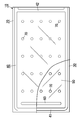
- the glass panel unit 10 of this embodiment is a vacuum heat insulating glass unit.
- the vacuum heat insulating glass unit is a kind of multilayer glass panel including at least a pair of glass panels, and has a vacuum space 50 between the pair of glass panels.
- a part (lower left) of the first glass panel 20 is broken and drawn so that the internal structure can be easily understood. Note that the top, bottom, left, and right directions in the figure are based on directions in which numbers can be read correctly.
- the glass panel unit 10 includes a first glass panel 20, a second glass panel 30, a seal 40, a vacuum space 50, and a spacer 70.
- the second glass panel 30 is disposed so as to face the first glass panel 20.
- the seal 40 joins the first glass panel 20 and the second glass panel 30 in a frame shape in an airtight manner.
- the vacuum space 50 is surrounded by the first glass panel 20, the second glass panel 30, and the seal 40.
- the spacer 70 is disposed between the first glass panel 20 and the second glass panel 30.
- the spacer 70 includes polyimide having a benzoxazole structure.
- the spacer 70 includes polyimide having a benzoxazole structure, the strength of the spacer 70 is increased. Furthermore, the spacer 70 is provided with elasticity by containing polyimide having a benzoxazole structure. Furthermore, the spacer 70 includes a polyimide having a benzoxazole structure, so that the heat resistance is increased. Therefore, the vacuum space 50 is formed well, and the glass panel unit 10 that is strong against external impact can be obtained.
- the first glass panel 20 includes a main body 21 that defines a planar shape of the first glass panel 20 and a coating 22.
- the main body 21 has a rectangular shape and has a first surface (outer surface; upper surface in FIG. 1) and a second surface (inner surface; lower surface in FIG. 1) parallel to each other in the thickness direction. Both the first surface and the second surface of the main body 21 are flat surfaces.
- the material of the main body 21 of the first glass panel 20 is, for example, soda lime glass, high strain point glass, chemically tempered glass, alkali-free glass, quartz glass, neoceram, or physically tempered glass. Note that the first glass panel 20 may not have the coating 22.
- the first glass panel 20 may be configured only from the main body 21.
- the coating 22 is formed on the second surface of the main body 21.
- the coating 22 is preferably an infrared reflecting film.
- the coating 22 is not limited to the infrared reflecting film, and may be a film having desired physical characteristics.
- the second glass panel 30 includes a main body 31 that defines the planar shape of the second glass panel 30.
- the main body 31 is rectangular and has a first surface (inner surface; upper surface in FIG. 1) and a second surface (outer surface; lower surface in FIG. 1) in the thickness direction parallel to each other. Both the first surface and the second surface of the main body 31 are flat surfaces.
- the material of the main body 31 of the second glass panel 30 is, for example, soda lime glass, high strain point glass, chemically tempered glass, alkali-free glass, quartz glass, neoceram, or physically tempered glass.
- the material of the main body 31 may be the same as the material of the main body 21.
- the planar shape of the main body 31 is the same as that of the main body 21. That is, the planar shape of the second glass panel 30 is the same as that of the first glass panel 20.
- the second glass panel 30 is composed only of the main body 31. That is, the main body 31 itself is the second glass panel 30.
- the second glass panel 30 may have a coating.
- the coating can be formed on the first surface of the body 31. This coating may be the same as the coating 22 of the first glass panel 20.
- the first glass panel 20 and the second glass panel 30 are arranged so that the second surface of the main body 21 and the first surface of the main body 31 are parallel to and opposed to each other. That is, the first surface of the main body 21 is directed to the outside of the glass panel unit 10, and the second surface of the main body 21 is directed to the inside of the glass panel unit 10. Further, the first surface of the main body 31 is directed to the inside of the glass panel unit 10, and the second surface of the main body 31 is directed to the outside of the glass panel unit 10.
- the thickness of the first glass panel 20 is not particularly limited, but is, for example, in the range of 1 to 10 mm.
- the thickness of the second glass panel 30 is not particularly limited, but is, for example, in the range of 1 to 10 mm.
- the first glass panel 20 and the second glass panel 30 may have the same thickness or different thicknesses. When the thickness of the 1st glass panel 20 and the 2nd glass panel 30 is the same, formation of the glass panel unit 10 becomes easy.
- the first glass panel 20 and the second glass panel 30 have the same outer edge in plan view.
- the glass panel unit 10 further includes a gas adsorber 60.
- the gas adsorber 60 is disposed in the vacuum space 50.
- the gas adsorber 60 has a long shape.
- the gas adsorber 60 is formed along the width direction of the second glass panel 30 on the second end side in the length direction of the second glass panel 30 (left end side in FIG. 2). That is, the gas adsorber 60 is disposed at the end of the vacuum space 50. In this way, the gas adsorber 60 can be made inconspicuous. Further, if the gas adsorber 60 is directly arranged on the glass panel, the gas adsorber 60 can be easily arranged. Note that the gas adsorber 60 can be provided at any location in the vacuum space 50.
- the gas adsorber 60 is used for adsorbing unnecessary gas (residual gas or the like).
- the unnecessary gas is, for example, a gas released when the seal 40 is formed.
- unnecessary gas is gas that enters the inside through the gap of the seal 40. When the gas increases, the degree of vacuum decreases and the heat insulating property may decrease.
- the gas adsorber 60 has a getter.
- a getter is a material that has the property of adsorbing molecules smaller than a predetermined size.
- the getter is, for example, an evaporation type getter.
- the evaporative getter is, for example, a zeolite or an ion exchanged zeolite.
- the seal 40 completely surrounds the vacuum space 50 and airtightly joins the first glass panel 20 and the second glass panel 30.
- the seal 40 is disposed between the first glass panel 20 and the second glass panel 30.
- the seal 40 has a rectangular frame shape.
- the degree of vacuum in the vacuum space 50 is a predetermined value or less.
- the predetermined value is, for example, 0.1 Pa.
- the vacuum space 50 can be formed by exhaust. Exhaust can be performed by forming a hole for exhausting at least one of the first glass panel 20, the second glass panel 30, and the seal 40, and sucking the gas inside. However, it is preferable that exhaust air to be described later is performed and no exhaust port exists in both the first glass panel 20 and the second glass panel 30. Thereby, the glass panel unit 10 with a good appearance can be obtained. In FIG. 1, the 1st glass panel 20 and the 2nd glass panel 30 do not have an exhaust port.
- Vacuum can be formed in the vacuum space 50 by exhausting while heating. Vacuum is enhanced by heating. Further, the seal 40 can be formed by heating. The heating temperature for forming the vacuum may be 300 ° C. or higher. Thereby, the vacuum property is further improved. A specific method for forming the vacuum space 50 will be described later.
- the seal 40 is formed with a thermal adhesive.
- the thermal adhesive is, for example, a glass frit.
- the glass frit is, for example, a low melting point glass frit.
- the low melting point glass frit is, for example, a bismuth glass frit, a lead glass frit, or a vanadium glass frit.
- the seal 40 may be formed of a plurality of thermal adhesives as will be described later.
- the glass panel unit 10 includes a plurality of spacers 70.
- the plurality of spacers 70 are used to maintain the distance between the first glass panel 20 and the second glass panel 30 at a predetermined distance.
- the space between the first glass panel 20 and the second glass panel 30 is more reliably secured by the spacer 70.
- the number of the spacers 70 may be one, in order to ensure the thickness between glass panels, two or more are preferable. When the plurality of spacers 70 are used, the strength of the glass panel unit 10 is increased.
- the plurality of spacers 70 are arranged in the vacuum space 50. Specifically, the plurality of spacers 70 are arranged at intersections of virtual rectangular grids. For example, the interval between the plurality of spacers 70 is in the range of 1 to 10 cm, specifically 2 cm. However, the size of the spacers 70, the number of the spacers 70, the interval between the spacers 70, and the arrangement pattern of the spacers 70 can be selected as appropriate.
- the spacer 70 has a columnar shape having a height substantially equal to the predetermined interval (the interval between the first glass panel 20 and the second glass panel 30).
- the spacer 70 may have a diameter in the range of 0.1 to 10 mm and a height in the range of 10 to 1000 ⁇ m.
- the spacer 70 may have a diameter of 0.5 mm and a height of 100 ⁇ m.
- Each spacer 70 may have a desired shape such as a prismatic shape or a spherical shape.
- the height of the spacer 70 defines the distance between the first glass panel 20 and the second glass panel 30, that is, the thickness of the vacuum space 50.
- the thickness of the vacuum space 50 may be in the range of 10 to 1000 ⁇ m, for example. Specifically, the thickness of the vacuum space 50 may be 100 ⁇ m.
- the spacer 70 is formed using a transparent material. Thereby, the spacer 70 becomes inconspicuous. However, each spacer 70 may be formed using an opaque material as long as it is sufficiently small.
- the material of the spacer 70 is selected so that the spacer 70 is not deformed in a first melting process, an exhaust process, and a second melting process, which will be described later.
- the material of the spacer 70 is selected to have a softening point (softening temperature) that is higher than the first softening point of the first thermal adhesive and the second softening point of the second thermal adhesive.
- the spacer 70 includes polyimide having a benzoxazole structure.
- Polyimide is a polymer having a structure represented by the following general formula (1).
- R and R ′ independently represent an organic group, and n represents an integer of 1 or more.
- Benzoxazole structure is introduced into the structure represented by the general formula (1).
- the benzoxazole structure is preferably introduced into the organic group R ′ of the general formula (1).
- Benzoxazole is represented by formula (2).
- the benzoxazole structure can be introduced into the polyimide by replacing hydrogen in the benzoxazole of formula (2) with other elements in the polyimide. Preferably, two or more hydrogens are replaced to introduce a benzoxazole structure into the polymer backbone.
- the polyimide having a benzoxazole structure may have a phenylbenzoxazole structure.
- Phenylbenzoxazole is represented by formula (3).
- the phenylbenzoxazole structure can be introduced into the polyimide by replacing hydrogen in the phenylbenzoxazole of formula (3) with other elements in the polyimide. Preferably, two or more hydrogens are replaced to introduce a phenylbenzoxazole structure into the polymer backbone.
- the polyimide having a benzoxazole structure may have a phenylenebisbenzoxazole structure.
- Phenylenebisbenzoxazole is shown by Formula (4).
- the phenylenebisbenzoxazole structure can be introduced into the polyimide by replacing hydrogen in the phenylenebisbenzoxazole of formula (4) with other elements in the polyimide. Preferably, two or more hydrogens are replaced to introduce a phenylenebisbenzoxazole structure into the polymer backbone.
- the polyimide having a benzoxazole structure may have a diphenylbenzobisoxazole structure.
- Diphenylbenzobisoxazole is represented by formula (5).
- the diphenylbenzobisoxazole structure can be introduced into the polyimide by replacing hydrogen in the diphenylbenzobisoxazole of formula (5) with another element in the polyimide. Preferably, two or more hydrogens are replaced to introduce a diphenylbenzobisoxazole structure into the polymer backbone.
- Polyimide is obtained by polycondensation of diamines and tetracarboxylic anhydrides.
- the diamine is preferably an aromatic diamine.
- the tetracarboxylic acid anhydrides are preferably aromatic tetracarboxylic acid anhydrides.
- a polyimide obtained by a reaction between an aromatic diamine and an aromatic tetracarboxylic anhydride is preferably used.
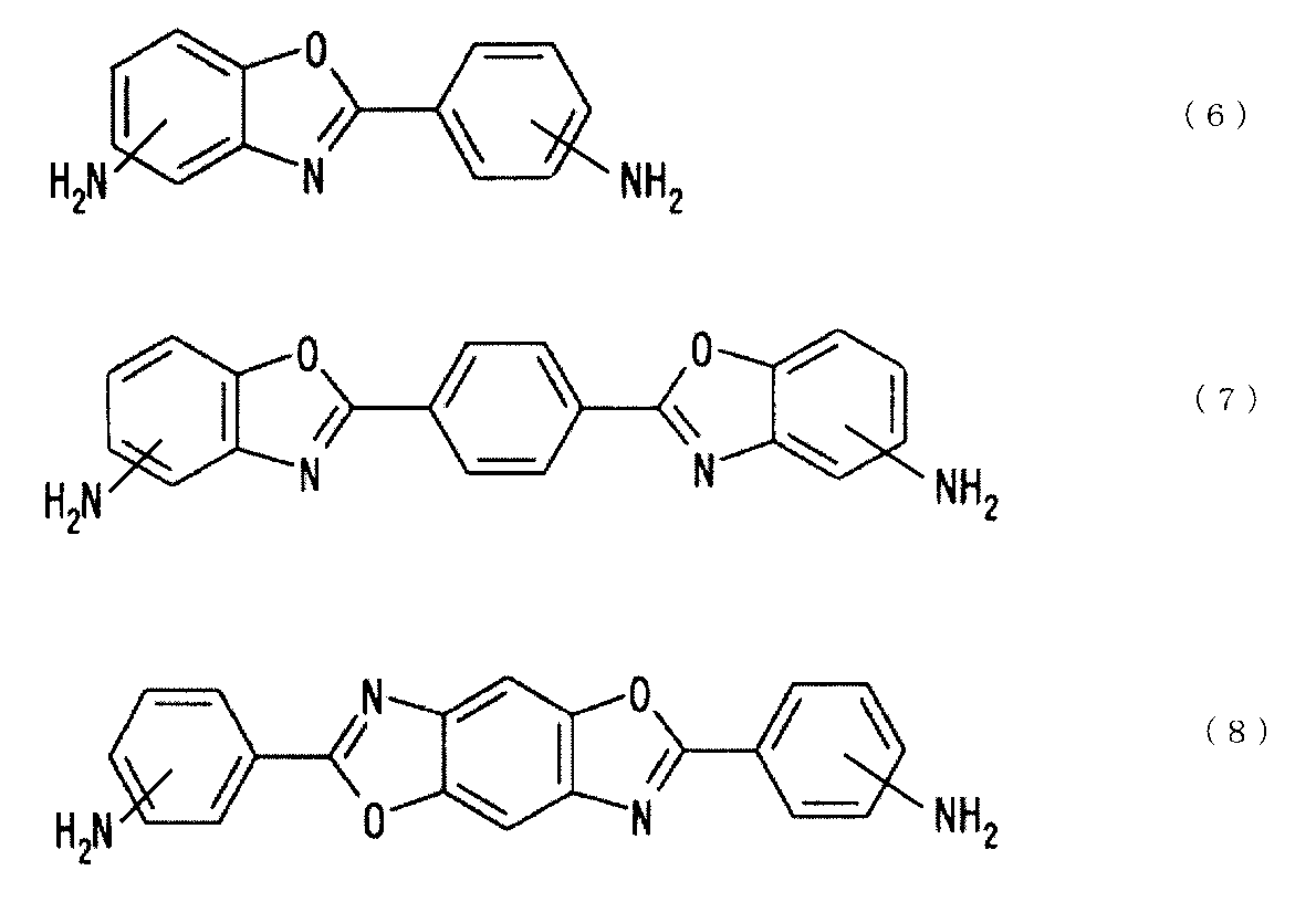
- Aromatic diamines preferably have a benzoxazole structure. By using aromatic diamines having a benzoxazole structure, the benzoxazole structure can be introduced into the polyimide.
- aromatic diamine having a benzoxazole structure examples include those represented by any of the following formulas (6), (7), and (8).
- aromatic diamine having the benzoxazole structure examples include 5-amino-2- (p-aminophenyl) benzoxazole, 6-amino-2- (p-aminophenyl) benzoxazole, 5- Amino-2- (m-aminophenyl) benzoxazole, 6-amino-2- (m-aminophenyl) benzoxazole, 2,2-p-phenylenebis (5-aminobenzoxazole), 1,5- (5 -Aminobenzoxazolo) -4- (5-aminobenzoxazolo) benzene, 2,6- (4,4'-diaminodiphenyl) benzo [1,2-d: 5,4-d '] bisoxazole, 2,6- (4,4′-diaminodiphenyl) benzo [1,2-d: 4,5-d ′] bisoxazole, 2,6- (3,4′-diaminodiph Nyl) benzo [1,2-
- aromatic diamines can be used alone or in combination of two or more.
- aromatic tetracarboxylic acid anhydrides include pyromellitic acid anhydride, 3,3 ′, 4,4′-biphenyltetracarboxylic acid anhydride, 4,4′-oxydiphthalic acid anhydride, 3,3 ′. , 4,4′-benzophenonetetracarboxylic anhydride, 3,3 ′, 4,4′-diphenylsulfonetetracarboxylic anhydride, 2,2-bis [4- (3,4-dicarboxyphenoxy) phenyl] Propanoic acid anhydride.
- aromatic tetracarboxylic acid anhydrides can be used alone or in combination of two or more.
- metal is widely used as a spacer for glass panel units.
- metals have high thermal conductivity and are disadvantageous for heat insulation.
- the glass panel unit tends to be weak against the impact.
- it is conceivable to use glass or ceramic for the spacer but in that case, the strength tends to decrease.
- a method using a resin having low thermal conductivity is also conceivable, it is difficult to select it in terms of strength and heat resistance.
- the spacer 70 having high strength is obtained by the polyimide described above.
- the spacer 70 has elasticity and improves impact resistance.
- the spacer 70 is resistant to heat and is not easily crushed.
- the spacer 70 has low thermal conductivity and improves heat insulation.
- the spacer 70 is preferably formed of polyimide having a viscoelastic coefficient at 400 ° C. larger than 500 MPa. Thereby, the glass panel unit 10 with high strength is obtained.
- the polyimide may have a viscoelastic coefficient at 400 ° C. of less than 1 ⁇ 10 6 MPa.
- the polyimide preferably has a viscoelastic coefficient at 400 ° C. of greater than 1000 MPa, more preferably greater than 1500 MPa, and even more preferably greater than 2000 MPa.
- the viscoelastic coefficient is measured with a viscoelasticity measuring device. For example, DMA (dynamic viscoelasticity measuring device) and TMA (thermomechanical analyzer) are exemplified.
- V 400 / V 20 to the viscoelastic coefficient V 20 at 20 ° C.
- V 400 / V 20 of the polyimide contained in the spacer 70 is preferably 0.1 or more.
- the ratio (V 400 / V 20 ) is more preferably 0.2 or more, further preferably 0.3 or more, and still more preferably 0.4 or more.
- the spacer 70 is preferably formed of polyimide having a thermal expansion coefficient smaller than 10 ppm / ° C. at 400 ° C. Thereby, the glass panel unit 10 with high strength is obtained.
- Polyimide may have a thermal expansion coefficient greater than 0.1 ppm / ° C. at 400 ° C. The thermal expansion coefficient is measured by a thermal expansion coefficient measuring device.
- TMA thermomechanical analyzer
- the spacer 70 is more preferably made of polyimide having a viscoelastic coefficient at 400 ° C. larger than 500 MPa and a thermal expansion coefficient smaller than 10 ppm / ° C. at 400 ° C.
- the spacer 70 is preferably formed of at least one polyimide film.
- the use of the polyimide film facilitates the formation of the spacer 70.
- the polyimide film can be cut into the shape of the spacer 70 and used as the spacer 70.
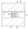
- FIG. 3 shows an example of the spacer 70.
- the spacer 70 is preferably a laminate of two or more films. At least one film of the laminate may be a polyimide film.
- the spacer 70 comprised by the laminated body of the two or more films 71 is shown.
- the spacer 70 shown in FIG. 3 can be incorporated in the glass panel unit 10 of FIG. In FIG. 3, three films 71 are used.
- the number of films 71 may be two, or four or more. If the thickness of the polyimide film increases, the physical properties may become unstable and the strength may vary. However, if a laminate is used, the thickness of one polyimide film can be reduced, so the thickness of the laminate increases. However, the physical properties can be stabilized. Therefore, the spacer 70 with stable strength and the like can be obtained.
- the thickness of the film 71 may be in the range of 1 to 50 ⁇ m, for example. When the thickness of the film 71 is within this range, the impact resistance can be increased efficiently. Moreover, the thickness for forming the space of the vacuum space 50 efficiently can be ensured, suppressing that the physical property of resin becomes unstable as the thickness of the film 71 is this range.
- the thickness of the film 71 may be 5 ⁇ m or more, may be 10 ⁇ m or more, and may be 20 ⁇ m or more. A thicker film 71 is advantageous in securing space.
- the film 71 may have a thickness of 45 ⁇ m or less, or 40 ⁇ m or less. The one where the thickness of the film 71 is smaller can suppress the destabilization of the resin.
- the one where the thickness of a polyimide film is smaller can suppress instability. If the thickness of the polyimide film becomes too large, the solvent may not be easily volatilized during production, and the physical properties may be lowered. Polyimide films have the advantages of low thermal expansion and high elasticity.
- the polyimide film can be manufactured using the aromatic diamine having the benzoxazole structure described above and the aromatic tetracarboxylic acid anhydride described above as raw materials. For example, first, they are condensed in a solvent to obtain a polyamic acid solution. Next, the polyamic acid solution is applied onto the support and dried to such an extent that self-supporting property is obtained, thereby obtaining a green film. Next, the green film is heat-treated to be imidized. Thus, a polyimide film is formed. At this time, the film may be stretched, but it is preferably unstretched. Thereby, the physical properties are further stabilized. An unstretched polyimide film is preferably used.
- the film 71 other than the polyimide film may be a film 71 formed of an appropriate material.
- a film other than a polyimide film is defined as another film. All of the film 71 included in the spacer 70 may be a polyimide film, or a part of the film 71 included in the spacer 70 may be a polyimide film and the other part may be another film.
- the other film includes one or more materials selected from glass, metal, ceramic, and graphite.
- the other film can be a glass film.
- the other film can be a metal film.
- the other film can be a ceramic film.
- the other film can be a graphite film.
- the glass film may be a thin glass.
- the glass film may contain glass fiber.
- the glass film may be a glass woven fabric.
- the glass film may be a glass nonwoven fabric.
- the metal film may be a metal foil.
- the metal film may be a rolled metal.
- a preferred example of the material for the metal film is stainless steel (SUS).
- the film described above may be read as a sheet.
- the ceramic film can be referred to as a ceramic sheet.
- the spacer 70 may have a structure in which, for example, a polyimide film is disposed on both sides in the stacking direction of the laminate, and another film is disposed between the two polyimide films. Thereby, the impact resistance is effectively increased.
- the stacking direction of the laminate is equal to the thickness direction of the glass panel unit 10.
- the two or more films 71 are bonded with an adhesive.
- An adhesive layer 72 is formed from the adhesive.
- a resin adhesive is used as the adhesive.
- the resin include a thermosetting resin and an ultraviolet curable resin.
- Lamination of the film 71 is performed in advance before the first glass panel 20 and the second glass panel 30 are bonded.
- the spacer 70 has two or more films 71 and one or more adhesive layers 72.
- the adhesive layer 72 is disposed between the two films 71.
- polyamic acid As the adhesive for adhering the film 71, polyamic acid is preferable.
- the two or more films 71 are bonded with polyamic acid.
- Polyamic acid has excellent adhesive strength and high heat resistance.
- the adhesive layer 72 is preferably formed from polyamic acid.
- the thickness of the adhesive layer 72 may be in the range of 0.1 to 10 ⁇ m, for example.
- the adhesive layer 72 is preferably smaller in thickness than the film 71.
- the thickness of the adhesive layer 72 is more preferably less than half the thickness of the film 71, and even more preferably less than 1/10.
- the thickness of the adhesive layer 72 may be 0.5 ⁇ m or more, or may be 0.8 ⁇ m or more.
- the thickness of the adhesive layer 72 may be 5 ⁇ m or less, or 3 ⁇ m or less.
- a laminate of films 71 is formed by placing an adhesive between two adjacent films 71, stacking two or more films 71, and heating and pressurizing a stack of films 71 (unbonded laminate). can do. At this time, it is preferable to heat and press with a vacuum press.
- the heating temperature of the press may be in the range of 300 to 500 ° C., for example.
- the pressure of the press may be in the range of 8 to 12 MPa, for example.
- the pressing time may be in the range of 5 minutes to 2 hours, for example.
- the laminated body of the film 71 can be used as the spacer 70 by cutting out according to the shape of the spacer 70 after two or more films 71 are bonded with an adhesive.
- the laminate can be cut by punching or the like.
- a cylindrical spacer 70 is obtained by cutting into a circular shape.
- the lamination direction of the film 71 may coincide with the thickness direction of the glass panel unit 10.
- the spacer 70 preferably has an area ratio with respect to the glass panel unit 10 in a range of 0.01 to 0.2% in plan view. Thereby, while making the spacer 70 inconspicuous, the intensity
- the plan view means that the glass panel unit 10 is viewed in the thickness direction. The thickness direction of the glass panel unit 10 is equal to the height direction of the spacer 70.
- the spacer 70 there is a spacer 70 including at least one material selected from glass, metal, ceramic, and graphite.
- the function of the spacer 70 can be improved.
- the strength of the spacer 70 can be increased.
- the thermal conductivity of the spacer 70 can be lowered.
- At least one material selected from glass, metal, ceramic, and graphite is defined herein as a functional material.
- the functional material may be included in the film 71 as described above, or may be included in the adhesive layer 72.
- a functional material may be included in the polyimide film. More preferably, the functional material is included in the adhesive layer 72. In that case, the functional material can be easily included in the spacer 70.
- the adhesive layer 72 containing a functional material is formed by mix
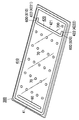
- FIGS. 4 to 10 are production examples of the glass panel unit 10.
- the glass panel unit 10 shown in FIGS. 1 to 3 can be manufactured by the method shown in FIGS. 4 to 10, the glass panel unit 10 having no exhaust port is manufactured.
- the glass panel unit 10 first obtains the temporary assembly 100 as shown in FIGS. 4 to 6, and then obtains the assembly 110 shown in FIGS. 7 to 9 by a predetermined process. Thereafter, as shown in FIG. 10, a glass panel unit 10 can be obtained by cutting a part from the assembly 110.
- the manufacturing method of the glass panel unit 10 has a preparation process, an assembly process, a sealing process, and a removal process. Note that the preparation step may be omitted.
- the preparation step is a step of preparing the first glass substrate 200, the second glass substrate 300, the frame 410, the partition 420, the gas adsorbent 60, and the plurality of spacers 70.
- the internal space 500, the air passage 600, and the exhaust port 700 can be formed by the preparation process.
- the first glass substrate 200 is a substrate used for the first glass panel 20.
- the first glass substrate 200 includes a glass plate 210 that defines a planar shape of the first glass substrate 200 and a coating 220.
- the glass plate 210 is a rectangular flat plate and has a first surface and a second surface in the thickness direction parallel to each other.
- the coating 220 is formed on the second surface of the glass plate 210.
- the glass plate 210 constitutes the main body 21 of the first glass panel 20.
- the first surface of the glass plate 210 corresponds to the first surface of the main body 21, and the second surface of the glass plate 210 corresponds to the second surface of the main body 21.
- the coating 220 constitutes the coating 22 of the first glass panel 20.
- the coating 220 may not be present.
- the second glass substrate 300 is a substrate used for the second glass panel 30.
- the second glass substrate 300 includes a glass plate 310 that defines the planar shape of the second glass substrate 300.
- the glass plate 310 is a rectangular flat plate and has a first surface and a second surface in the thickness direction parallel to each other.
- the second glass substrate 300 constitutes the main body 31 of the second glass panel 30.
- the first surface of the glass plate 310 corresponds to the first surface of the main body 31, and the second surface of the glass plate 310 corresponds to the second surface of the main body 31.
- the planar shape and planar size of the glass plate 310 are the same as those of the glass plate 210. That is, the planar shape of the second glass substrate 300 is the same as that of the first glass substrate 200.
- the thickness of the glass plate 310 is the same as that of the glass plate 210.
- the second glass substrate 300 is composed only of the glass plate 310. That is, the glass plate 310 is the second glass substrate 300 itself.
- the second glass substrate 300 is disposed so as to face the first glass substrate 200. Specifically, the first glass substrate 200 and the second glass substrate 300 are arranged such that the second surface of the glass plate 210 and the first surface of the glass plate 310 are parallel to and face each other.
- the frame body 410 is disposed between the first glass substrate 200 and the second glass substrate 300, and joins the first glass substrate 200 and the second glass substrate 300 in an airtight manner. As a result, as shown in FIG. 6, an internal space 500 surrounded by the frame body 410, the first glass substrate 200, and the second glass substrate 300 is formed.
- the frame body 410 is formed of a thermal adhesive (a first thermal adhesive having a first softening point).
- the first thermal adhesive is, for example, a glass frit.
- the glass frit is, for example, a low melting point glass frit.
- the low melting point glass frit is, for example, a bismuth glass frit, a lead glass frit, or a vanadium glass frit.
- the frame 410 has a rectangular frame shape.
- the planar shape of the frame 410 is the same as that of the glass plates 210 and 310, but the planar size of the frame 410 is smaller than the glass plates 210 and 310.
- the frame body 410 is formed along the outer periphery of the second glass substrate 300. That is, the frame 410 is formed so as to surround almost all the region on the second glass substrate 300.
- the partition 420 is disposed in the internal space 500. As shown in FIG. 6, the partition 420 partitions the internal space 500 into an exhaust space 510 and a ventilation space 520.
- the exhaust space 510 is a space to be exhausted later, and the ventilation space 520 is a space used for exhausting the exhaust space 510.
- the partition 420 has a first end side in the length direction (left-right direction in FIG. 4) of the second glass substrate 300 from the center of the second glass substrate 300 so that the exhaust space 510 is larger than the ventilation space 520. 4 on the right end side).
- the partition 420 includes a wall portion 421 and a pair of blocking portions 422 (a first blocking portion 4221 and a second blocking portion 4222).
- the wall portion 421 is formed along the width direction of the second glass substrate 300.
- the width direction means a direction along the short side of the rectangular temporary assembly 100 in FIG. However, both ends in the length direction of the wall portion 421 are not in contact with the frame body 410.
- the pair of blocking portions 422 extend from both ends in the length direction of the wall portion 421 to the first end side in the length direction of the second glass substrate 300.
- the partition 420 is formed of a thermal adhesive (second thermal adhesive having a second softening point).
- the second thermal adhesive is, for example, a glass frit.
- the glass frit is, for example, a low melting point glass frit.
- the low melting point glass frit is, for example, a bismuth glass frit, a lead glass frit, or a vanadium glass frit.
- the second thermal adhesive is the same as the first thermal adhesive, and the second softening point and the first softening point are equal.
- the gas adsorber 60 is disposed in the exhaust space 510. Specifically, the gas adsorber 60 is disposed at the end of the exhaust space 510. Further, the gas adsorber 60 is located away from the partition 420 and the ventilation path 600. Therefore, it is possible to reduce the possibility that the gas adsorber 60 hinders exhaust when exhausting the exhaust space 510.
- the plurality of spacers 70 are the same as those described with reference to FIGS. That is, the spacer 70 can be preferably composed of a laminate of the film 71 shown in FIG. As described above, the spacer 70 is obtained by bonding two or more films 71 including at least one polyimide film with an adhesive, and then cutting the adhesive. A step of forming the spacer 70 may be added to the preparation step. As shown in FIG. 4, the plurality of spacers 70 can be arranged at predetermined intervals in the vertical and horizontal directions.
- the spacer 70 as a member before being incorporated into the glass panel unit 10 and the spacer 70 after the glass panel unit 10 is formed may have different heights.
- the spacer 70 can be compressed in the height direction by being sandwiched between two glass panels.
- the spacer 70 includes polyimide having a benzoxazole structure, the strength is increased, so that the spacer 70 can be prevented from being compressed too much. Therefore, it becomes easy to ensure the thickness of the vacuum space 50.
- strength of the glass panel unit 10 can be raised. Further, the collapse of the spacer 70 is suppressed, and the appearance (aesthetics) of the glass panel unit 10 can be improved.
- the ventilation path 600 connects the exhaust space 510 and the ventilation space 520 in the internal space 500.
- the ventilation path 600 includes a first ventilation path 610 and a second ventilation path 620.
- the first air passage 610 is a space formed between the first blocking portion 4221 and the portion of the frame 410 that faces the first blocking portion 4221.
- the second ventilation path 620 is a space formed between the second blocking portion 4222 and the portion of the frame 410 that faces the second blocking portion 4222.
- the exhaust port 700 is a hole that connects the ventilation space 520 and the external space.
- the exhaust port 700 is used to exhaust the exhaust space 510 through the ventilation space 520 and the ventilation path 600. Therefore, the ventilation path 600, the ventilation space 520, and the exhaust port 700 constitute an exhaust path for exhausting the exhaust space 510.
- the exhaust port 700 is formed in the second glass substrate 300 so as to connect the ventilation space 520 and the external space. Specifically, the exhaust port 700 is located at a corner portion of the second glass substrate 300.
- the preparation process is performed by the members as described above.
- the preparation step includes first to sixth steps. Note that the order of the second to sixth steps may be changed as appropriate.
- the first step is a step of forming the first glass substrate 200 and the second glass substrate 300 (substrate forming step). For example, in the first step, the first glass substrate 200 and the second glass substrate 300 are produced. In the first step, the first glass substrate 200 and the second glass substrate 300 are cleaned as necessary.
- the second step is a step of forming the exhaust port 700.
- the exhaust port 700 is formed in the second glass substrate 300.
- the second glass substrate 300 is cleaned as necessary.
- the exhaust port 700 may be provided in the first glass substrate 200.
- the third step is a step of forming the frame body 410 and the partition 420 (sealing material forming step).
- the material of the frame 410 (first thermal adhesive) and the material of the partition 420 (second thermal adhesive) are used for the second glass substrate 300 (first surface of the glass plate 310) using a dispenser or the like. ) Apply on top.
- the material of the frame 410 and the material of the partition 420 are dried and temporarily fired.
- coated is heated at 480 degreeC for 20 minutes.
- the first glass substrate 200 may be heated together with the second glass substrate 300. That is, the first glass substrate 200 may be heated under the same conditions as the second glass substrate 300 (20 minutes at 480 ° C.). Thereby, the difference of the curvature of the 1st glass substrate 200 and the 2nd glass substrate 300 can be reduced.
- the fourth step is a step of installing the spacer 70 (spacer installation step).
- a plurality of spacers 70 are formed in advance, and the plurality of spacers 70 are installed at predetermined positions on the second glass substrate 300 using a chip mounter or the like.
- the plurality of spacers 70 may be formed using a known thin film forming technique.
- the spacer 70 may be formed by applying polyimide or a composition for forming polyimide onto the second glass substrate 300.
- the fifth step is a step of forming the gas adsorbent 60 (gas adsorbent forming step).
- the gas adsorber 60 is formed by applying a solution in which getter powder is dispersed to a predetermined position of the second glass substrate 300 and drying the solution.
- the frame 410, the partition 420, the ventilation path 600, the exhaust port 700, the gas adsorbent 60, and the plurality of spacers 70 as shown in FIG. 4 are formed. Two glass substrates 300 are obtained.
- the sixth step is a step of arranging the first glass substrate 200 and the second glass substrate 300 (arrangement step).
- the first glass substrate 200 and the second glass substrate 300 are arranged such that the second surface of the glass plate 210 and the first surface of the glass plate 310 are parallel to and face each other.
- FIG. 5 shows a state in which the first glass substrate 200 is overlaid on the second glass substrate 300.
- each member (frame body 410, partition 420, etc.) is arranged on the second glass substrate 300, but each member may be arranged on the first glass substrate 200.
- the assembly process is a process of preparing the temporary assembly 100. Specifically, in the assembly process, the first glass substrate 200 and the second glass substrate 300 are joined to prepare the temporary assembly 100. That is, the assembly process is a process (first melting process) in which the first glass substrate 200 and the second glass substrate 300 are hermetically bonded by the frame body 41.
- the first glass substrate 200 and the second glass substrate 300 are hermetically bonded by once melting the first thermal adhesive at a predetermined temperature (first melting temperature) equal to or higher than the first softening point. .
- the first glass substrate 200 and the second glass substrate 300 are hermetically bonded by the frame body 410.
- the first glass substrate 200 and the second glass substrate 300 are placed in a melting furnace and heated at a first melting temperature for a predetermined time (first melting time).
- the first glass substrate 200 and the second glass substrate 300 are hermetically bonded by the thermal adhesive of the frame 410, but the air passage 600 is blocked by the partition 420. It is set so that there is no. That is, the lower limit of the first melting temperature is the first softening point, but the upper limit of the first melting temperature is set so that the air passage 600 is not blocked by the partition 420. For example, when the first softening point and the second softening point are 434 ° C., the first melting temperature is set to 440 ° C.
- the first melting time is, for example, 10 minutes.
- gas is released from the frame 410, but this gas may be adsorbed by the gas adsorber 60.
- the temporary assembly 100 shown in FIG. 6 is obtained by the assembly process (first melting process) described above.
- the temporary assembly 100 includes a first glass substrate 200, a second glass substrate 300, a frame body 410, an internal space 500, a partition 420, an air passage 600, an exhaust port 700, a gas adsorber 60, A plurality of spacers 70.
- the sealing step is a step of obtaining the assembly 110 by performing the predetermined processing on the temporary assembly 100.
- the sealing process includes an exhaust process and a melting process (second melting process). That is, the exhaust process and the second melting process correspond to the predetermined process.
- the exhaust process is a process of exhausting the exhaust space 510 at a predetermined temperature (exhaust temperature) through the ventilation path 600, the ventilation space 520, and the exhaust port 700 to form the vacuum space 50.
- a predetermined temperature exhaust temperature
- a vacuum property increases.
- Exhaust is performed using, for example, a vacuum pump.
- the vacuum pump is connected to the temporary assembly 100 by an exhaust pipe 810 and a seal head 820.
- the exhaust pipe 810 is joined to the second glass substrate 300 so that the inside of the exhaust pipe 810 and the exhaust port 700 communicate with each other.
- a seal head 820 is attached to the exhaust pipe 810, whereby the suction port of the vacuum pump is connected to the exhaust port 700.
- the first melting step, the exhausting step, and the second melting step are performed while the first glass substrate 200 and the second glass substrate 300 are placed in the melting furnace.
- the second glass substrate 300 is provided with a frame body 410, a partition 420, an air passage 600, an exhaust port 700, a gas adsorber 60, and a plurality of spacers 70.
- the exhaust pipe 810 is joined to the second glass substrate 300 at least before the first melting step.
- the exhaust space 510 is exhausted through the ventilation path 600, the ventilation space 520, and the exhaust port 700 for a predetermined time (exhaust time) at a predetermined exhaust temperature.
- the exhaust temperature is set higher than the activation temperature of the getter of the gas adsorber 60 (for example, 350 ° C.) and lower than the first softening point and the second softening point (for example, 434 ° C.).
- the exhaust temperature is preferably 300 ° C. or higher.
- the exhaust temperature is 390 ° C. In this way, the frame body 410 and the partition 420 are not deformed. Further, the getter of the gas adsorber 60 is activated, and molecules (gas) adsorbed by the getter are released from the getter.
- the exhaust time is set so that a vacuum space 50 having a desired degree of vacuum (for example, a degree of vacuum of 0.1 Pa or less) is obtained.
- the exhaust time is set to 120 minutes.
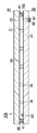
- the second melting step is a step of forming the seal 40 that surrounds the vacuum space 50 by deforming the partition 420 to form the partition wall 42 that closes the ventilation path 600.
- the partition wall 42 is formed by deforming the partition 420 by once melting the second thermal adhesive at a predetermined temperature (second melting temperature) equal to or higher than the second softening point.
- second melting temperature a predetermined temperature
- the first glass substrate 200 and the second glass substrate 300 are heated for a predetermined time (second melting time) at the second melting temperature in the melting furnace.
- the second melting temperature and the second melting time are set so that the second thermal adhesive is softened and the partition wall 42 that blocks the air passage 600 is formed.
- the lower limit of the second melting temperature is the second softening point (434 ° C.).
- the second melting step aims to deform the partition 420, and therefore the second melting temperature is higher than the first melting temperature (440 ° C.).
- the second melting temperature is set to 460 ° C.
- the second melting time is, for example, 30 minutes.
- the vacuum space 50 is separated from the ventilation space 520. Therefore, the vacuum space 50 cannot be exhausted with the vacuum pump.
- the frame body 410 and the partition wall 42 are heated, and thus gas may be released from the frame body 410 and the partition wall 42.
- the gas released from the frame body 410 and the partition wall 42 is adsorbed by the gas adsorber 60 in the vacuum space 50. Therefore, the vacuum degree of the vacuum space 50 is prevented from deteriorating. That is, it is prevented that the heat insulation of the glass panel unit 10 deteriorates.
- the gas adsorber 60 can sufficiently adsorb the gas released from the frame body 410 and the partition wall 42 in the second melting step. That is, it is possible to prevent the gas adsorber 60 from sufficiently adsorbing the gas released from the frame body 410 and the partition wall 42 and deteriorating the vacuum degree of the vacuum space 50.
- the exhaust space 510 is exhausted through the vent path 600, the vent space 520, and the exhaust port 700 continuously from the exhaust step. That is, in the second melting step, the partition wall 42 that blocks the air passage 600 by deforming the partition 420 while exhausting the exhaust space 510 through the air passage 600, the air space 520, and the exhaust port 700 at the second melting temperature. Form. This further prevents the vacuum degree of the vacuum space 50 from being deteriorated during the second melting step. However, in the second melting step, it is not always necessary to exhaust the exhaust space 510 through the vent path 600, the vent space 520, and the exhaust port 700.
- the exhaust space 510 is evacuated to the vacuum space 50 through the ventilation path 600, the ventilation space 520, and the exhaust port 700 at a predetermined temperature (exhaust temperature).
- the exhaust temperature is higher than the activation temperature of the getter of the gas adsorber 60.
- the partition 420 is deformed to form the partition wall 42 that closes the ventilation path 600, thereby forming the seal 40 surrounding the vacuum space 50 (see FIG. 8). Since the partition 420 contains the second thermal adhesive, the partition 420 is deformed by once melting the second thermal adhesive at a predetermined temperature (second melting temperature) that is equal to or higher than the second softening point. Can be formed. The first melting temperature is lower than the second melting temperature. Thereby, when joining the 1st glass substrate 200 and the 2nd glass substrate 300 with the frame 410, it can prevent that the partition 420 deform
- the partition 420 may be formed of a material that is more deformable when melted than the frame body 410.
- the partition 420 is modified such that the first blocking part 4221 closes the first ventilation path 610 and the second blocking part 4222 blocks the second ventilation path 620.
- the partition wall 42 obtained by deforming the partition 420 in this way separates (vacually) the vacuum space 50 from the ventilation space 520.
- the partition (second portion) 42 and the portion (first portion) 41 corresponding to the vacuum space 50 in the frame 410 constitute the seal 40 surrounding the vacuum space 50.
- the vacuum space 50 is formed by exhausting the exhaust space 510 through the ventilation space 520 and the exhaust port 700. Since the vacuum space 50 is completely sealed by the first glass substrate 200, the second glass substrate 300, and the seal 40, the vacuum space 50 is separated from the ventilation space 520 and the exhaust port 700.
- the seal 40 has a first portion 41 and a second portion 42.
- the first portion 41 is a portion corresponding to the vacuum space 50 in the frame 410. That is, the first portion 41 is a portion facing the vacuum space 50 in the frame body 410.
- the first portion 41 is substantially U-shaped and constitutes three sides of the four sides of the seal 40.
- the second portion 42 is a partition wall obtained by deforming the partition 420.
- the second portion 42 is I-shaped and constitutes the remaining one of the four sides of the seal 40.
- the spacer 70 secures a space between the first glass substrate 200 and the second glass substrate 300.
- the spacer 70 containing polyimide having a benzoxazole structure when used, it becomes easier to secure the thickness of the vacuum space 50 than in other cases. This is because polyimide having a benzoxazole structure has high heat resistance and strength.
- polyimide having a benzoxazole structure has high heat resistance and strength.
- the spacer is liable to be crushed. When crushing occurs, the thickness of the vacuum space can be reduced. Moreover, the occurrence of crushing tends to cause a decrease in heat insulation. Further, the collapse of the spacer may cause a decrease in strength. Further, the collapse of the spacer may cause deterioration of the appearance of the glass panel unit.
- the assembly 110 shown in FIGS. 7 to 9 is obtained by the sealing process described above.
- the assembly 110 includes a first glass substrate 200, a second glass substrate 300, a seal 40, a vacuum space 50, a ventilation space 520, a gas adsorber 60, and a plurality of spacers 70.
- a part (lower right) of the first glass substrate 200 is broken and drawn so that the internal structure can be easily understood.
- the removal step is a step of obtaining the glass panel unit 10 that is a portion having the vacuum space 50 by removing the portion 11 having the ventilation space 520 from the assembly 110.
- the assembly 110 taken out from the melting furnace is cut along a cutting line 900, and a predetermined portion (glass panel unit) 10 having a vacuum space 50, and a ventilation space. And a portion (unnecessary portion) 11 having 520.
- the unnecessary portion 11 mainly includes a portion 230 corresponding to the ventilation space 520 in the first glass substrate 200, a portion 320 corresponding to the ventilation space 520 in the second glass substrate 300, and a ventilation space in the frame 410. And a portion 411 corresponding to 520. Considering the manufacturing cost of the glass panel unit 10, it is preferable that the unnecessary portion 11 is small.
- FIG. 10 shows a state where the unnecessary portion 11 is removed from the assembly 110.
- Cutting is performed by an appropriate cutting device.
- the cutting device include a scriber and a laser. If the 1st glass substrate 200 and the 2nd glass substrate 300 are cut
- the shape of the cutting line 900 is determined by the shape of the glass panel unit 10. Since the glass panel unit 10 is rectangular, the cutting line 900 is a straight line along the length direction of the wall 42.
- the first glass panel 20 is a portion corresponding to the vacuum space 50 in the first glass substrate 200.
- the second glass panel 30 is a portion corresponding to the vacuum space 50 in the second glass substrate 300.
- the exhaust port 700 for forming the vacuum space 50 exists in the part 320 corresponding to the ventilation space 520 in the second glass substrate 300, and the exhaust pipe 810 is connected to the part 320. Therefore, the second glass panel 30 does not have the exhaust port 700.
- the glass panel unit (10) has a rectangular shape, but the glass panel unit (10) may have a desired shape such as a circular shape or a polygonal shape. That is, the first glass panel (20), the second glass panel (30), and the seal (40) may have a desired shape such as a circular shape or a polygonal shape instead of a rectangular shape.
- each shape of a 1st glass substrate (200), a 2nd glass substrate (300), a frame (410), and a partition (42) is not limited to the shape of the said embodiment, Desired shape What is necessary is just a shape which can obtain a glass panel unit (10).
- size of a glass panel unit (10) are determined according to the use of a glass panel unit (10).
- first surface and the second surface of the main body (21) of the first glass panel (20) are not limited to planes.
- neither the first surface nor the second surface of the main body (31) of the second glass panel (30) is limited to a flat surface.
- the main body (21) of the first glass panel (20) and the main body (31) of the second glass panel (30) may not have the same planar shape and planar size. Moreover, the main body (21) and the main body (31) may not have the same thickness. Moreover, the main body (21) and the main body (31) may not be formed of the same material. Similarly, the glass plate (210) of the first glass substrate (200) and the glass plate (310) of the second glass substrate (300) may not have the same planar shape and planar size. Moreover, the glass plate (210) and the glass plate (310) do not need to have the same thickness. The glass plate (210) and the glass plate (310) may not be formed of the same material.
- the seal (40) may not have the same planar shape as the first glass panel (20) and the second glass panel (30).
- the frame (410) may not have the same planar shape as the first glass substrate (200) and the second glass substrate (300).
- the first glass panel (20) may further include a coating having desired physical properties and formed on the second plane of the main body (21).
- the first glass panel (20) may not include the coating (22). That is, the 1st glass panel (20) may be comprised only with the main body (21).
- the second glass panel (30) may further include a coating having desired physical characteristics.
- the coating only needs to include at least one of thin films formed on the first plane and the second plane of the main body (31), for example.
- the coating is, for example, a film that reflects light of a specific wavelength (infrared reflective film, ultraviolet reflective film).
- the frame (410) is formed of the first thermal adhesive.
- the frame (410) may include other elements such as a core material in addition to the first thermal adhesive. That is, the frame (410) only needs to contain the first thermal adhesive.
- the frame (410) is formed so that the substantially all area
- the frame (410) only needs to be formed so as to surround a predetermined region on the second glass substrate (300). That is, the frame (410) does not need to be formed so as to surround almost the entire region of the second glass substrate (300).
- the assembly (110) may have two or more frames (410). That is, the assembly (110) may have two or more internal spaces (500). In this case, two or more glass panel units (10) can be obtained from one assembly (110).
- the partition (420) is formed of the second thermal adhesive.
- the partition (420) may include other elements such as a core material in addition to the second thermal adhesive. That is, the partition (420) only needs to contain the second thermal adhesive.
- the both ends of the partition (420) are not connected with the frame (410).
- the clearance gap between the both ends of a partition (420) and a frame (410) is a ventilation path (610,620).
- only one of the both ends of the partition (420) may not be connected to the frame (410). In this case, one air passage (between the partition (420) and the frame (410) is provided. 600) is formed. Or the both ends of the partition (420) may be connected with the frame (410).
- the ventilation path (600) may be a through hole formed in the partition (420).
- the air passage (600) may be a gap between the partition (420) and the first glass substrate (200).
- the partition (420) may be formed of two or more partitions arranged at intervals. In this case, the ventilation path (600) may be a gap between two or more partitions.
- the internal space (500) is partitioned into one exhaust space (510) and one ventilation space (520).
- the internal space (500) may be partitioned into one or more exhaust spaces (510) and one or more ventilation spaces (520).
- two or more glass panel units (10) can be obtained from one assembly (110).
- the second thermal adhesive is the same as the first thermal adhesive, and the second softening point and the first softening point are equal.
- the second thermal adhesive may be a material different from the first thermal adhesive.
- the second thermal adhesive may have a second softening point different from the first softening point of the first thermal adhesive.
- the second softening point is preferably higher than the first softening point.
- the first melting temperature can be set to be equal to or higher than the first softening point and lower than the second softening point. By doing so, it is possible to prevent the partition (420) from being deformed in the first melting step.
- first adhesive and the second thermal adhesive are not limited to glass frit, and may be, for example, a low melting point metal or a hot melt adhesive.
- a melting furnace is used for heating the frame (410), the gas adsorber (60), and the partition (420).
- the heating can be performed by an appropriate heating means.
- the heating means is, for example, a laser or a heat transfer plate connected to a heat source.
- the air passage (600) includes two air passages (610, 620). However, the air passage (600) may include only one air passage, or three or more air passages (600, 620). You may be comprised with the ventilation path. Moreover, the shape of the ventilation path (600) is not specifically limited.
- the exhaust port (700) is formed in the second glass substrate (300).
- the exhaust port (700) may be formed in the glass plate (210) of the first glass substrate (200), or may be formed in the frame (410). In short, the exhaust port (700) should just be formed in the unnecessary part (11).
- the getter of the gas adsorbent (60) is an evaporative getter, but the getter may be a non-evaporable getter.
- the non-evaporable getter reaches a predetermined temperature (activation temperature) or higher, the adsorbed ability is recovered by allowing the adsorbed molecules to enter the inside.
- activation temperature a predetermined temperature
- it does not release adsorbed molecules, so if non-evaporable getters adsorb more than a certain amount of molecules, the adsorption capacity is restored even if heated above the activation temperature. No longer.
- the gas adsorbent (60) is elongated, but may be other shapes. Further, the gas adsorber (60) does not necessarily have to be at the end of the vacuum space (50).
- the gas adsorber (60) is a liquid containing getter powder (for example, a dispersion obtained by dispersing getter powder in the liquid, or dissolving the getter powder in the liquid. The solution obtained in this manner is applied.
- the gas adsorber (60) may include a substrate and a getter fixed to the substrate. Such a gas adsorber (60) can be obtained by immersing the substrate in a liquid containing getter powder and drying it.
- the substrate may have a desired shape, for example, a long rectangular shape.
- the gas adsorbent (60) may be a film formed entirely or partially on the surface (first surface) of the glass plate (310) of the second glass substrate (300). Such a gas adsorbent (60) can be obtained by coating the surface (first surface) of the glass plate (310) of the second glass substrate (300) with a liquid containing getter powder.
- the gas adsorber (60) may be included in the spacer (70).
- the spacer (70) is formed of a material including a getter
- the spacer (70) including the gas adsorbent (60) can be obtained.
- the adhesive layer (72) may contain a getter.
- the gas adsorber (60) may be a solid formed by a getter. Such a gas adsorber (60) is relatively large and may not be disposed between the first glass substrate (200) and the second glass substrate (300). In this case, a recess may be formed in the glass plate (310) of the second glass substrate (300), and the gas adsorber (60) may be disposed in this recess.
- the gas adsorber (60) may be arranged in advance in the package so that the getter does not adsorb molecules. In this case, after the second melting step, the package is broken and the gas adsorber (60) is exposed to the vacuum space (50).
- the glass panel unit (10) includes the gas adsorber (60), but the glass panel unit (10) may not include the gas adsorber (60).
- the glass panel unit (10) includes a plurality of spacers (70), but the glass panel unit (10) may include a single spacer (70).
- the spacer (70) includes polyimide having a benzoxazole structure.
- the spacer (70) does not contain a polyimide having a benzoxazole structure, and may contain a polymer having a viscoelastic coefficient greater than 500 MPa at 400 ° C. Also in that case, a glass panel unit (10) with high strength is obtained.
- the polymer contained in the spacer (70) may have a viscoelastic coefficient of less than 1 ⁇ 10 6 MPa at 400 ° C.
- the polymer preferably has a viscoelastic coefficient at 400 ° C. of more than 1000 MPa, more preferably more than 1500 MPa, and still more preferably more than 2000 MPa.
- the spacer (70) may be a laminate of such polymer films.
- the spacer (70) does not contain polyimide having a benzoxazole structure, and the ratio of the viscoelastic coefficient V 400 at 400 ° C. to the viscoelastic coefficient V 20 at 20 ° C. (V 400 / V 20 ) May contain a polymer of 0.1 or more.
- the ratio (V 400 / V 20 ) is more preferably 0.2 or more, further preferably 0.3 or more, and still more preferably 0.4 or more.
- the spacer (70) does not contain the polyimide which has a benzoxazole structure, and may contain the polymer whose thermal expansion coefficient in 400 degreeC is smaller than 10 ppm / degreeC.
- the polymer contained in the spacer (70) may have a thermal expansion coefficient greater than 0.1 ppm / ° C. at 400 ° C. Furthermore, the spacer (70) does not contain a polyimide having a benzoxazole structure, and the viscoelastic coefficient at 400 ° C. is larger than 500 MPa, and the thermal expansion coefficient at 400 ° C. is smaller than 10 ppm / ° C. It may contain a polymer.
- the glass panel unit (10) having no exhaust port is formed by removing the unnecessary portion (11).
- the glass panel unit (10) has the exhaust port. You may do it.
- an exhaust port may be provided in at least any one of a 1st glass panel (20) and a 2nd glass panel (30). In order to maintain the vacuum of the vacuum space (50), the exhaust port is closed.
- the exhaust port can be closed by a cap material.
- the glass panel unit (10) does not have an exhaust port.
- FIG. 11 shows a modification of the glass panel unit (glass panel unit 10A).
- the glass panel unit 10 ⁇ / b> A has an exhaust port 700 in the second glass panel 30.
- the exhaust port 700 is closed by a sealing portion 81.
- the sealing part 81 is formed from the exhaust pipe 810.
- Sealing portion 81 can be formed by, for example, thermal welding of glass constituting exhaust pipe 810.
- a cap 80 is disposed outside the sealing portion 81.
- the cap 80 covers the sealing portion 81. Since the cap 80 covers the sealing portion 81, the exhaust port 700 can be closed high. Further, the cap 80 can suppress damage at the exhaust port 700 portion.
- the glass panel unit 10A is the same as the glass panel unit 10 of FIGS.
- the same components as those in the glass panel unit 10 in FIGS. 1 to 3 are denoted by the same reference numerals, and the descriptions given in FIGS. 1 to 3 can be appropriately applied to these components.
- the glass panel unit 10 ⁇ / b> A can be manufactured according to the method for manufacturing the temporary assembly 100. Since it is not necessary to remove the portion having the exhaust port 700, the glass panel unit 10A can be easily manufactured.
- Example 2 About the glass panel unit, the difference in the physical property by the difference in a spacer was tested.
- a spacer a spacer using a polyimide film having a benzoxazole structure (Example 1), a spacer using a polyimide film having no benzoxazole structure (Comparative Examples 1 and 2), and a stainless steel spacer (Comparative Example) 3) and were prepared.
- the spacer of Example 1 had a diameter of 0.5 mm and a height of 0.116 mm.
- the spacer of Comparative Example 1 had a diameter of 0.5 mm and a height of 0.125 mm.
- the spacer of Comparative Example 2 had a diameter of 0.8 mm and a height of 0.125 mm.
- the spacer of Comparative Example 3 was SUS304, the diameter was 0.4 mm, and the height was 0.15 mm.
- the size of the spacer is a value before being incorporated into the glass panel unit.
- Example 1 Toyobo “Zenomax” (registered trademark) was used as a polyimide film.
- the polyimide film used in Example 1 is a polyimide whose viscoelastic coefficient at 400 ° C. is larger than 500 MPa (2500 MPa) and whose thermal expansion coefficient at 400 ° C. is smaller than 10 ppm / ° C. (about 1 ppm / ° C.). Is formed.
- Kaneka's “Apical” (registered trademark) was used as the polyimide film.
- the polyimides of Comparative Examples 1 and 2 are condensates (abbreviation: PDMA / ODA) of pyromellitic dianhydride and 4,4'-diaminodiphenyl ether.
- the polyimide films used in Comparative Examples 1 and 2 have a viscoelastic coefficient at 400 ° C. smaller than 500 MPa (250 MPa) and a thermal expansion coefficient at 400 ° C. larger than 10 ppm / ° C. (about 28 ppm / ° C.). It is made of polyimide.
- Table 1 shows the results of comparing the strength (impact strength), thermal conductivity (glass thermal permeability), and spacer diameter of the glass panel unit.
- the impact strength is an average height (unit: cm) in which a 225 g sphere is dropped on the glass panel unit and the surface of the glass panel unit is damaged.
- the glass thermal conductivity (unit: W / m 2 ⁇ K) is measured with a heat conduction measuring device.
- the spacer diameter is the spacer diameter after the glass panel unit is formed. The spacer can be sandwiched between the two glass panels, and the spacer diameter can be increased as compared with the case before the spacer is incorporated into the glass panel unit. If the spacer diameter is too large, the spacer becomes conspicuous and the aesthetics deteriorate.
- the impact strength is preferably more than 50 cm.
- the thermal conductivity is preferably 1.0 W / m 2 ⁇ K or less.
- the spacer diameter is preferably 0.6 mm or less.
- the glass panel unit of Example 1 has high impact strength, low thermal conductivity, and a small spacer diameter.
- Comparative Example 3 has low impact strength and high thermal conductivity.
- Comparative Example 2 has high thermal conductivity and a large spacer diameter. In Comparative Example 2, the spacer diameter was increased because the spacer was selected so that the impact strength exceeded 50 cm. In Comparative Example 1, the impact strength is low and the spacer diameter is large.
- the spacer diameter after forming the glass panel unit can be compared between the spacer containing polyimide having a benzoxazole structure (diameter 500 ⁇ m) and the spacer containing polyimide not having a benzoxazole structure (diameter 500 ⁇ m) (implementation).
- the exhaust conditions for forming the vacuum space are 450 ° C. and 15 minutes.
- the diameter was increased but remained at 560 ⁇ m, whereas in the spacer containing the polyimide not having the benzoxazole structure, the diameter was increased to 700 ⁇ m.
- an increase in the spacer diameter is suppressed.
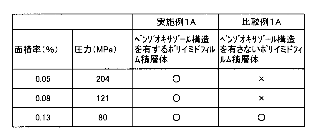
- Example 1A As shown in Table 2, in Example 1A, a high-strength glass panel unit was obtained.
- the spacer used in Example 1 is made of polyimide having a benzoxazole structure and has a diameter of 0.5 mm.
- the spacer used in Comparative Example 1 is made of polyimide having no benzoxazole structure and has a diameter of 0.5 mm.
- the press pressure was 200 MPa.
- the spacer shape was “X” when crushing was confirmed by visual inspection, and “ ⁇ ” when crushing was not confirmed. The results are shown in Table 3.
- the viscoelastic coefficient suddenly decreased at 300 ° C. or higher.
- the degree of decrease in the viscoelastic coefficient is small.
- the viscoelastic coefficient at 400 ° C. is larger than 500 MPa.
- the ratio of the viscoelastic coefficient V 400 at 400 ° C. to the viscoelastic coefficient V 20 at 20 ° C. is 0.1 or more. It is advantageous.
Abstract
Description


ガラスパネルユニットについて、スペーサの違いによる物性の違いを試験した。スペーサとして、ベンゾオキサゾール構造を有するポリイミドフィルムを用いたスペーサ(実施例1)と、ベンゾオキサゾール構造を有さないポリイミドフィルムを用いたスペーサ(比較例1、2)と、ステンレス製のスペーサ(比較例3)と、を準備した。実施例1のスペーサは、直径0.5mm、高さ0.116mmとした。比較例1のスペーサは、直径0.5mm、高さ0.125mmとした。比較例2のスペーサは、直径0.8mm、高さ0.125mmとした。比較例3のスペーサは、SUS304、直径0.4mm、高さ0.15mmとした。なお、スペーサのサイズは、ガラスパネルユニットに組み込まれる前の値である。


Claims (8)
- 第1ガラスパネルと、
前記第1ガラスパネルと対向するように配置された第2ガラスパネルと、
前記第1ガラスパネルと前記第2ガラスパネルとを枠状に気密に接合するシールと、
前記第1ガラスパネルと前記第2ガラスパネルと前記シールとで囲まれた真空空間と、
前記第1ガラスパネルと前記第2ガラスパネルとの間に配置された少なくとも1つのスペーサと、を備え、
前記スペーサは、ベンゾオキサゾール構造を有するポリイミドを含む、
ガラスパネルユニット。 - 第1ガラスパネルと、
前記第1ガラスパネルと対向するように配置された第2ガラスパネルと、
前記第1ガラスパネルと前記第2ガラスパネルとを枠状に気密に接合するシールと、
前記第1ガラスパネルと前記第2ガラスパネルと前記シールとで囲まれた真空空間と、
前記第1ガラスパネルと前記第2ガラスパネルとの間に配置された少なくとも1つのスペーサと、を備え、
前記スペーサは、400℃のときの粘弾性係数が500MPaよりも大きいポリマーを含む、
ガラスパネルユニット。 - 前記スペーサは、2以上のフィルムの積層体である、
請求項1又は2に記載のガラスパネルユニット。 - 前記真空空間は、加熱しながら排気することによって真空が形成された、
請求項1乃至3のいずれか1項に記載のガラスパネルユニット。 - 前記加熱の温度は、300℃以上である、
請求項4に記載のガラスパネルユニット。 - 前記第1ガラスパネル及び前記第2ガラスパネルは、排気口を有していない、
請求項1乃至5のいずれか1項に記載のガラスパネルユニット。 - 前記スペーサは、平面視したときの前記ガラスパネルユニットに対する面積率が、0.01~0.2%の範囲内である、
請求項1乃至6のいずれか1項に記載のガラスパネルユニット。 - 前記スペーサは、ガラス、金属、セラミック、及びグラファイトから選ばれる少なくとも1つの材料を含む、
請求項1乃至7のいずれか1項に記載のガラスパネルユニット。
Priority Applications (9)
| Application Number | Priority Date | Filing Date | Title |
|---|---|---|---|
| PL15862623T PL3225601T3 (pl) | 2014-11-27 | 2015-11-27 | Szyba zespolona |
| ES15862623T ES2758546T3 (es) | 2014-11-27 | 2015-11-27 | Unidad de panel de vidrio |
| EA201791159A EA034127B1 (ru) | 2014-11-27 | 2015-11-27 | Блок стеклянных панелей |
| EP15862623.4A EP3225601B1 (en) | 2014-11-27 | 2015-11-27 | Glass panel unit |
| JP2016561255A JP6384799B2 (ja) | 2014-11-27 | 2015-11-27 | ガラスパネルユニット |
| US15/528,165 US10519710B2 (en) | 2014-11-27 | 2015-11-27 | Glass panel unit |
| DK15862623T DK3225601T3 (da) | 2014-11-27 | 2015-11-27 | Glaspanelenhed |
| CN201580063726.2A CN107001132B (zh) | 2014-11-27 | 2015-11-27 | 玻璃面板单元 |
| US16/683,021 US11047166B2 (en) | 2014-11-27 | 2019-11-13 | Glass panel unit |
Applications Claiming Priority (2)
| Application Number | Priority Date | Filing Date | Title |
|---|---|---|---|
| JP2014240319 | 2014-11-27 | ||
| JP2014-240319 | 2014-11-27 |
Related Child Applications (2)
| Application Number | Title | Priority Date | Filing Date |
|---|---|---|---|
| US15/528,165 A-371-Of-International US10519710B2 (en) | 2014-11-27 | 2015-11-27 | Glass panel unit |
| US16/683,021 Continuation US11047166B2 (en) | 2014-11-27 | 2019-11-13 | Glass panel unit |
Publications (1)
| Publication Number | Publication Date |
|---|---|
| WO2016084383A1 true WO2016084383A1 (ja) | 2016-06-02 |
Family
ID=56073971
Family Applications (1)
| Application Number | Title | Priority Date | Filing Date |
|---|---|---|---|
| PCT/JP2015/005908 WO2016084383A1 (ja) | 2014-11-27 | 2015-11-27 | ガラスパネルユニット |
Country Status (10)
| Country | Link |
|---|---|
| US (2) | US10519710B2 (ja) |
| EP (1) | EP3225601B1 (ja) |
| JP (1) | JP6384799B2 (ja) |
| CN (2) | CN107001132B (ja) |
| DK (1) | DK3225601T3 (ja) |
| EA (2) | EA201992438A3 (ja) |
| ES (1) | ES2758546T3 (ja) |
| HU (1) | HUE047463T2 (ja) |
| PL (1) | PL3225601T3 (ja) |
| WO (1) | WO2016084383A1 (ja) |
Cited By (4)
| Publication number | Priority date | Publication date | Assignee | Title |
|---|---|---|---|---|
| JPWO2016084382A1 (ja) * | 2014-11-27 | 2017-10-12 | パナソニックIpマネジメント株式会社 | ガラスパネルユニット |
| JPWO2017169731A1 (ja) * | 2016-03-31 | 2019-02-14 | パナソニックIpマネジメント株式会社 | ガラスパネルユニット |
| US10450792B2 (en) | 2014-12-10 | 2019-10-22 | Panasonic Intellectual Property Management Co., Ltd. | Glass panel unit |
| US20210300822A1 (en) * | 2018-07-18 | 2021-09-30 | Panasonic Intellectual Property Management Co., Ltd. | Glass panel unit and method for manufacturing the glass panel unit |
Families Citing this family (6)
| Publication number | Priority date | Publication date | Assignee | Title |
|---|---|---|---|---|
| EA201992438A3 (ru) * | 2014-11-27 | 2020-10-30 | Панасоник Интеллекчуал Проперти Менеджмент Ко., Лтд. | Блок стеклянных панелей |
| CN107428602A (zh) * | 2015-03-13 | 2017-12-01 | 松下知识产权经营株式会社 | 制造玻璃面板单元的方法、制造玻璃窗的方法以及制造具有间隔件的玻璃基板的设备 |
| EP3438063B1 (en) * | 2016-03-31 | 2022-11-02 | Panasonic Intellectual Property Management Co., Ltd. | Glass panel unit and glass window |
| CN107337358B (zh) * | 2017-01-26 | 2018-12-14 | 连玉琦 | 一种真空玻璃及其制备方法 |
| US20220081961A1 (en) * | 2019-01-14 | 2022-03-17 | Vkr Holding A/S | Frame providing restriction of thermal deflection of a vig unit edge |
| US20210087872A1 (en) * | 2019-09-23 | 2021-03-25 | Guardian Glass, LLC | Low thermal conductivity metal-polymer-metal sandwich composite spacer system for vacuum insulated glass (vig) units, vig units including composite spacers, and methods of making the same |
Citations (3)
| Publication number | Priority date | Publication date | Assignee | Title |
|---|---|---|---|---|
| US20020106463A1 (en) * | 2001-02-05 | 2002-08-08 | Wang Yei-Ping (Mimi) H. | Vacuum IG window unit with polymer spacers |
| US20120088045A1 (en) * | 2010-10-08 | 2012-04-12 | Guardian Industries Corp. | Vacuum insulated glass (VIG) unit including nano-composite pillars, and/or methods of making the same |
| WO2013172034A1 (ja) * | 2012-05-18 | 2013-11-21 | パナソニック株式会社 | 複層ガラスの製造方法 |
Family Cites Families (15)
| Publication number | Priority date | Publication date | Assignee | Title |
|---|---|---|---|---|
| US5124185A (en) * | 1989-10-03 | 1992-06-23 | Ppg Industries, Inc. | Vacuum insulating unit |
| US5173561A (en) * | 1990-07-24 | 1992-12-22 | Daychem Laboratories, Inc. | Heat resistant polyimide-benzoxazole polymers and composites thereof |
| JPH11315668A (ja) * | 1998-05-07 | 1999-11-16 | Nippon Sheet Glass Co Ltd | ガラスパネル |
| JP4567894B2 (ja) * | 2001-01-29 | 2010-10-20 | 日本板硝子株式会社 | ガラスパネル |
| JP2002294185A (ja) | 2001-03-29 | 2002-10-09 | Ube Ind Ltd | 粘着テ−プ |
| CN101065336A (zh) * | 2004-11-26 | 2007-10-31 | 旭硝子株式会社 | 复层玻璃及其制造方法 |
| JP2008044229A (ja) * | 2006-08-16 | 2008-02-28 | Toyobo Co Ltd | 多層ポリイミドフィルム及びその製造方法 |
| CN101945965A (zh) * | 2007-12-28 | 2011-01-12 | 3M创新有限公司 | 柔性封装膜系统 |
| JP2011094059A (ja) | 2009-10-30 | 2011-05-12 | Teijin Dupont Films Japan Ltd | 二軸配向ポリエステルフィルムおよびその製造方法 |
| DE102009058789B4 (de) * | 2009-12-18 | 2011-09-22 | Futech Gmbh | Wärmedämmendes Verglasungselement und Verfahren zu dessen Herstellung |
| KR20140112477A (ko) | 2011-12-08 | 2014-09-23 | 닛토덴코 가부시키가이샤 | 점탄성체 |
| WO2013132866A1 (ja) * | 2012-03-07 | 2013-09-12 | パナソニック株式会社 | 複層ガラス |
| US9878954B2 (en) * | 2013-09-13 | 2018-01-30 | 3M Innovative Properties Company | Vacuum glazing pillars for insulated glass units |
| US10533365B2 (en) * | 2014-11-27 | 2020-01-14 | Panasonic Intellectual Property Management Co., Ltd. | Glass panel unit |
| EA201992438A3 (ru) * | 2014-11-27 | 2020-10-30 | Панасоник Интеллекчуал Проперти Менеджмент Ко., Лтд. | Блок стеклянных панелей |
-
2015
- 2015-11-27 EA EA201992438A patent/EA201992438A3/ru unknown
- 2015-11-27 ES ES15862623T patent/ES2758546T3/es active Active
- 2015-11-27 HU HUE15862623A patent/HUE047463T2/hu unknown
- 2015-11-27 CN CN201580063726.2A patent/CN107001132B/zh active Active
- 2015-11-27 EA EA201791159A patent/EA034127B1/ru not_active IP Right Cessation
- 2015-11-27 JP JP2016561255A patent/JP6384799B2/ja active Active
- 2015-11-27 PL PL15862623T patent/PL3225601T3/pl unknown
- 2015-11-27 EP EP15862623.4A patent/EP3225601B1/en active Active
- 2015-11-27 WO PCT/JP2015/005908 patent/WO2016084383A1/ja active Application Filing
- 2015-11-27 US US15/528,165 patent/US10519710B2/en active Active
- 2015-11-27 DK DK15862623T patent/DK3225601T3/da active
- 2015-11-27 CN CN202010083993.9A patent/CN111170656A/zh active Pending
-
2019
- 2019-11-13 US US16/683,021 patent/US11047166B2/en active Active
Patent Citations (3)
| Publication number | Priority date | Publication date | Assignee | Title |
|---|---|---|---|---|
| US20020106463A1 (en) * | 2001-02-05 | 2002-08-08 | Wang Yei-Ping (Mimi) H. | Vacuum IG window unit with polymer spacers |
| US20120088045A1 (en) * | 2010-10-08 | 2012-04-12 | Guardian Industries Corp. | Vacuum insulated glass (VIG) unit including nano-composite pillars, and/or methods of making the same |
| WO2013172034A1 (ja) * | 2012-05-18 | 2013-11-21 | パナソニック株式会社 | 複層ガラスの製造方法 |
Non-Patent Citations (1)
| Title |
|---|
| See also references of EP3225601A4 * |
Cited By (8)
| Publication number | Priority date | Publication date | Assignee | Title |
|---|---|---|---|---|
| JPWO2016084382A1 (ja) * | 2014-11-27 | 2017-10-12 | パナソニックIpマネジメント株式会社 | ガラスパネルユニット |
| US10450792B2 (en) | 2014-12-10 | 2019-10-22 | Panasonic Intellectual Property Management Co., Ltd. | Glass panel unit |
| EP3231777B1 (en) * | 2014-12-10 | 2020-08-05 | Panasonic Intellectual Property Management Co., Ltd. | Glass panel unit |
| JPWO2017169731A1 (ja) * | 2016-03-31 | 2019-02-14 | パナソニックIpマネジメント株式会社 | ガラスパネルユニット |
| EP3438064A4 (en) * | 2016-03-31 | 2019-04-10 | Panasonic Intellectual Property Management Co., Ltd. | GLASS |
| EP3611142A1 (en) * | 2016-03-31 | 2020-02-19 | Panasonic Intellectual Property Management Co., Ltd. | Method of manufacturing a glass panel unit |
| US10619403B2 (en) | 2016-03-31 | 2020-04-14 | Panasonic Intellectual Property Management Co., Ltd. | Glass panel unit |
| US20210300822A1 (en) * | 2018-07-18 | 2021-09-30 | Panasonic Intellectual Property Management Co., Ltd. | Glass panel unit and method for manufacturing the glass panel unit |
Also Published As
| Publication number | Publication date |
|---|---|
| ES2758546T3 (es) | 2020-05-05 |
| CN111170656A (zh) | 2020-05-19 |
| EA201992438A3 (ru) | 2020-10-30 |
| US20170328122A1 (en) | 2017-11-16 |
| PL3225601T3 (pl) | 2020-03-31 |
| US20200080363A1 (en) | 2020-03-12 |
| DK3225601T3 (da) | 2019-12-02 |
| JPWO2016084383A1 (ja) | 2017-09-28 |
| EA201992438A2 (ru) | 2020-07-31 |
| EP3225601B1 (en) | 2019-09-04 |
| EA034127B1 (ru) | 2019-12-30 |
| US10519710B2 (en) | 2019-12-31 |
| US11047166B2 (en) | 2021-06-29 |
| CN107001132B (zh) | 2020-03-10 |
| HUE047463T2 (hu) | 2020-04-28 |
| EP3225601A4 (en) | 2017-11-01 |
| JP6384799B2 (ja) | 2018-09-05 |
| EP3225601A1 (en) | 2017-10-04 |
| EA201791159A1 (ru) | 2017-10-31 |
| CN107001132A (zh) | 2017-08-01 |
Similar Documents
| Publication | Publication Date | Title |
|---|---|---|
| JP6384799B2 (ja) | ガラスパネルユニット | |
| WO2016084382A1 (ja) | ガラスパネルユニット | |
| JP6447935B2 (ja) | ガラスパネルユニット | |
| JP6528335B2 (ja) | ガラスパネルユニット | |
| JP6471916B2 (ja) | ガラスパネルユニット、ガラスパネルユニットの仮組立て品、ガラスパネルユニットの組立て品、ガラスパネルユニットの製造方法 | |
| JP6767702B2 (ja) | ガラスパネルユニットおよびガラス窓 | |
| JP2016069232A (ja) | ガラスパネルユニット、ガラスパネルユニットの組立て品、ガラスパネルユニットの製造方法 | |
| JP2019178063A (ja) | ガラスパネルユニットの製造方法 | |
| JPWO2016051714A1 (ja) | ガラスパネルユニット及びその検査方法 | |
| WO2018062140A1 (ja) | ガラスパネルユニット、ガラス窓およびガラスパネルユニットの製造方法 | |
| WO2017169731A1 (ja) | ガラスパネルユニット | |
| JPWO2019239846A1 (ja) | ガラスパネルユニットの製造方法 |
Legal Events
| Date | Code | Title | Description |
|---|---|---|---|
| 121 | Ep: the epo has been informed by wipo that ep was designated in this application |
Ref document number: 15862623 Country of ref document: EP Kind code of ref document: A1 |
|
| ENP | Entry into the national phase |
Ref document number: 2016561255 Country of ref document: JP Kind code of ref document: A |
|
| REEP | Request for entry into the european phase |
Ref document number: 2015862623 Country of ref document: EP |
|
| WWE | Wipo information: entry into national phase |
Ref document number: 15528165 Country of ref document: US |
|
| NENP | Non-entry into the national phase |
Ref country code: DE |
|
| WWE | Wipo information: entry into national phase |
Ref document number: 201791159 Country of ref document: EA |