WO2016079977A1 - 車両用空調装置 - Google Patents
車両用空調装置 Download PDFInfo
- Publication number
- WO2016079977A1 WO2016079977A1 PCT/JP2015/005702 JP2015005702W WO2016079977A1 WO 2016079977 A1 WO2016079977 A1 WO 2016079977A1 JP 2015005702 W JP2015005702 W JP 2015005702W WO 2016079977 A1 WO2016079977 A1 WO 2016079977A1
- Authority
- WO
- WIPO (PCT)
- Prior art keywords
- air
- heat exchanger
- unit case
- vehicle
- right direction
- Prior art date
- Legal status (The legal status is an assumption and is not a legal conclusion. Google has not performed a legal analysis and makes no representation as to the accuracy of the status listed.)
- Ceased
Links
Images




Classifications
-
- B—PERFORMING OPERATIONS; TRANSPORTING
- B60—VEHICLES IN GENERAL
- B60H—ARRANGEMENTS OF HEATING, COOLING, VENTILATING OR OTHER AIR-TREATING DEVICES SPECIALLY ADAPTED FOR PASSENGER OR GOODS SPACES OF VEHICLES
- B60H1/00—Heating, cooling or ventilating devices
-
- B—PERFORMING OPERATIONS; TRANSPORTING
- B60—VEHICLES IN GENERAL
- B60H—ARRANGEMENTS OF HEATING, COOLING, VENTILATING OR OTHER AIR-TREATING DEVICES SPECIALLY ADAPTED FOR PASSENGER OR GOODS SPACES OF VEHICLES
- B60H1/00—Heating, cooling or ventilating devices
- B60H1/00007—Combined heating, ventilating, or cooling devices
- B60H1/00021—Air flow details of HVAC devices
- B60H1/00064—Air flow details of HVAC devices for sending air streams of different temperatures into the passenger compartment
-
- B—PERFORMING OPERATIONS; TRANSPORTING
- B60—VEHICLES IN GENERAL
- B60H—ARRANGEMENTS OF HEATING, COOLING, VENTILATING OR OTHER AIR-TREATING DEVICES SPECIALLY ADAPTED FOR PASSENGER OR GOODS SPACES OF VEHICLES
- B60H1/00—Heating, cooling or ventilating devices
- B60H1/00007—Combined heating, ventilating, or cooling devices
- B60H1/00021—Air flow details of HVAC devices
- B60H2001/00078—Assembling, manufacturing or layout details
- B60H2001/00092—Assembling, manufacturing or layout details of air deflecting or air directing means inside the device
Definitions
- the present disclosure relates to a vehicle air conditioner in which cold air flowing out from an air outflow surface of a cooling heat exchanger and hot air flowing out from an air outflow surface of a heating heat exchanger are mixed and blown out as conditioned air into a vehicle interior. It relates to the device.
- This vehicle air conditioner is an air mix type vehicle air conditioner that adjusts the air volume ratio between the warm air flowing through the heating heat exchanger and the cold air flowing bypassing the heating heat exchanger.
- the baffle member is formed to extend toward the case wall surface facing the air outflow surface.
- Each baffle member has a hook shape in which the windward side portion in the cold air flow direction is closed and the leeward side portion is opened.
- the baffle member guides the hot air from the air outflow surface of the heating heat exchanger toward the case wall surface. Then, the warm air flowing through the baffle members flows in a direction intersecting the flow direction of the cold air flowing between the baffle members, and flows to the opposing case wall surfaces. Thereby, the ratio of the warm air flow which reaches
- the configuration of a member that guides wind is simple, and the mixing of cold air and hot air is controlled so that the air at a desired temperature can be supplied to each outlet with easy adjustment. It aims at providing the vehicle air conditioner which can do.
- the vehicle air conditioner of the present disclosure includes a unit case, a cooling heat exchanger, a heating heat exchanger, an air mix door, a blowout port, a stepped portion, a corner hot air passage, and a guide member.
- the unit case forms an air passage through which air flows.
- the cooling heat exchanger is disposed across a cool air passage formed in the unit case, and cools the air.
- the heating heat exchanger is disposed downstream of the cooling heat exchanger in the air flow direction, and heats the air.
- the air mix door is provided between the cooling heat exchanger and the heating heat exchanger in the air flow direction, and passes through the cold air and the heating heat exchanger that bypass the heating heat exchanger in the unit case. Adjust the air volume ratio with warm air.
- a blower outlet is provided in a unit case, and blows off the conditioned air temperature-controlled by the air mix door to the several site
- the step portion is provided in a wall portion of the unit case downstream of the cooling heat exchanger in the unit case, and a portion of the unit case that has a narrow width in the left-right direction for housing the cooling heat exchanger, A portion having a width in the left-right direction wider than a portion for accommodating the heat exchanger for cooling is connected, and the width in the left-right direction of the unit case is expanded more than the cool air passage.
- the corner hot air passage is formed at the corners on both sides in the left-right direction adjacent to the step portion, and a part of the hot air that has passed through the heating heat exchanger flows.
- the guide member is provided on the downstream side of the cooling heat exchanger, and guides the cold air that has passed through the cooling heat exchanger in the left-right direction toward the corner hot air passage.
- the guide member branches the cold air that has passed through the air outflow surface of the cooling heat exchanger and guides it toward the left and right steps.
- the step portion can provide a hot air passage having a larger left-right width than the cold air passage on the downstream side of the cooling heat exchanger.
- a part of the warm air from the heat exchanger for heating rising the corner hot air passage located at the left and right ends of the warm air passage, and the cold air from the cooling heat exchanger branched to the left and right by the guide member, Can be mixed at the corners of the unit case. Since the corner hot air passage improves the mixing of the cold air and the hot air, the required volume in the unit case can be reduced.
- a desired temperature can be supplied to each of the plurality of outlets by adjusting the shape and size of the guide member.
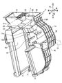
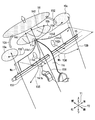
- FIG. 1st Embodiment It is a schematic block diagram in the unit case of the vehicle air conditioner in 1st Embodiment. It is a perspective view which shows the structure in the unit case of FIG. It is explanatory drawing explaining the effect
- the arrow Y1 indicates the vertical direction (vertical direction) of the vehicle
- the arrow Y2 indicates the front-rear direction based on the traveling direction of the vehicle.
- the upper direction in the vertical direction indicates the ceiling side of the vehicle
- the lower side indicates the floor side of the vehicle.
- the left and right directions refer to the left and right with respect to the traveling direction of the vehicle.
- FIG. 1 schematically illustrates a configuration of a unit case 1 of a vehicle air conditioner according to the present disclosure.
- the unit case 1 that forms an air passage through which air flows toward the passenger compartment flows conditioned air from a blower (not shown) toward the downstream side of the air passage.
- the unit case 1 includes a heating heat exchanger 3 for heating air and a cooling heat exchanger 4 for cooling air, and the air flowing in the unit case 1 is heated for heating and the cooling unit 3. It arrange
- cool air flows above the heating heat exchanger 3 from the cooling heat exchanger 4 as indicated by arrows Y33, Y41, Y42, and Y34.
- the cooling heat exchanger 4 exchanges heat between the fluid flowing inside the cooling heat exchanger 4 and the air passing through the cooling heat exchanger 4, and the air flows out of the cooling heat exchanger 4 as cold air. It has an air outflow surface 4a.
- a warm air passage through which the warm air flows through the heating heat exchanger 3 toward the upper side of the unit case 1.
- This hot air passage is a passage through which the hot air that has passed through the heating heat exchanger 3 flows upward.
- the warm air passages include a central warm air passage through which the warm air flowing out from the heating heat exchanger 3 through the central portion of the unit case 1 flows as shown by an arrow Y38 in FIG.
- the corner hot air passages 10a and 10c that flow from the heat exchanger 3 as indicated by arrows Y37 and Y39 in FIG.
- the corner hot air passages 10a and 10c are a pair of corner hot air passages facing in the left-right direction.
- the central hot air passages and the corner hot air passages 10a and 10c are not passages partitioned by walls, but are one passage communicating with each other.
- the central hot air passages and the corner hot air passages 10a and 10c are also mixed regions in which the cold air and the hot air cooled by the cooling heat exchanger are mixed.
- the air mix door 6 is a well-known slide door, and is provided on the upstream side of the heat exchanger 3 for heating.
- the air mix door 6 passes through the cooling heat exchanger 4, then passes through the cooling heat exchanger 3, cool air that bypasses the heating heat exchanger 3, and then passes through the heating heat exchanger 3. Adjust the air volume ratio with the warm air. Thereby, the air mix door 6 adjusts the temperature of the conditioned air mixed with the cold air and the hot air.
- a plurality of air outlets 7, 81, 82 for blowing the conditioned air to a plurality of parts in the vehicle compartment are provided in the unit case 1 and open upward.
- the unit case 1 is formed with step portions 91 and 92 for causing wall portions to bulge at right angles on the left and right sides of the downstream side of the air outflow surface 4a of the cooling heat exchanger 4.
- the wall surface of the unit case has a step of dimension Wa due to the presence of the step portions 91 and 92.
- the step portions 91 and 92 increase the right and left width of the air passage, and a space for forming the corner hot air passages 10a and 10c through which part of the hot air flows as indicated by arrows Y37 and Y39 is secured.
- 2 illustrates only one of the unit case 1 in the left-right direction, but the step portions 91 and 92 are symmetrically present on both sides of the unit case 1 in the left-right direction.
- the unit case 1 includes a unit case portion (first case portion 1a) having a narrow width in the left-right direction that houses the cooling heat exchanger 4, and a downstream of the first case portion 1a in the air flow direction.
- the step portions 91 and 92 connect the first case portion 1a and the second case portion 1b, and expand the width of the unit case 1 in the left-right direction.
- the step portions 91 and 92 extend in the left-right direction from the first case portion 1a downstream of the cooling heat exchanger 4 and are connected to the second case portion 1b, and the second case portion 1b is connected to the first case portion. It expands in the left-right direction from 1a.
- the corner hot air passage 10a is defined by the second case portion 1b and the step portion 91
- the corner hot air passage 10b is defined by the second case portion 1b and the step portion 92.
- the step portions 91 and 92 extend from the lower end in the vertical direction Y1 of the unit case 1 to the vicinity of the guide member 11.
- the step portions 91 and 92 may extend from above the lower end in the vertical direction Y1 of the unit case 1 to the vicinity of the guide member 11, so long as the hot air can be guided and a corner hot air passage can be formed. good.
- the guide member 11 is provided on the downstream side of the air outflow surface 4a of the heat exchanger 4 for cooling.
- the guide member 11 branches the cool air that has not passed toward the heat exchanger 3 for heating out of the cool air that has passed through the air outflow surface 4a, as shown by arrows Y33, Y41, Y42, and Y34 in FIG.
- the guide member 11 guides the cold air from the cooling heat exchanger 4 toward the left and right corner hot air passages 10a and 10c.
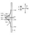
- the guide member 11 has a shape (gull shape) that spreads to the left and right as shown in FIG.
- the cold air flowing as shown by the arrows Y33 and Y34 branched by the guide member 11 collides with the hot air in the corner hot air passages 10a and 10c rising from below and is mixed to become the conditioned air 56. It flows to the center face air outlet 7 and the side face air outlets 81 and 82.
- the evaporator which comprises the heat exchanger 4 for cooling is provided so that the air path (1st case part 1a) in the unit case 1 may be crossed.
- the air passage in which the cooling heat exchanger 4 is provided is a cold air passage.
- a heater core constituting the heating heat exchanger 3 is formed on the downstream side of the evaporator.
- hot water serving as engine cooling water flows, and heats the air passing through the heating heat exchanger 3.
- a part of the warm air heated by the heating heat exchanger 3 rises in the corner warm air passages 10a and 10c along the step portions 91 and 92 as indicated by arrows Y37 and Y39 in FIG. .
- the guide member 11 includes a first guide blade portion 11b1, a second guide blade portion 11b2, a top portion 11a, and a wall portion 11c connected to the top portion 11a.
- the guide member 11 is fixed to the wall surface of the unit case 1 by a fixed shaft 15 penetrating the wall portion 11c.
- a defroster air outlet 21 that blows warm air to the windshield is provided.
- a defroster door 21d for adjusting the amount of air blown to the windshield is provided so as to rotate with the shaft.
- FIG. 1 is a partially broken view of the defroster outlet 21 and virtually shows the internal defroster door 21d.
- the face door 23 is connected to the rotary shaft 22 so as to control the air flow flowing out from the center face air outlet 7.
- the pair of left and right side face doors 24 is provided on the rotating shaft 22 and controls the air flow flowing out from the side face outlets 81 and 82.
- FIG. 2 shows only one side face door 24, and the other side face door is located in the side face outlet 82.
- the guide member 11 includes a first guide blade portion 11b1 extending from the top portion 11a toward one side (right side in FIG. 3) in the left-right direction, and a second guide extending from the top portion 11a toward the other side (left side in FIG. 3) in the left-right direction. And a wing part 11b2.
- the first guide blade portion 11b1 and the second guide blade portion 11b2 extend so as to curve (convex) in a direction away from the cooling heat exchanger 4 (air flow downstream).
- the first guide wing part 11b1 and the second guide wing part 11b2 are respectively connected to the fixed shaft 15 at the ends opposite to the top part 11a in the left-right direction (first end part 11d1 and second end part 11d2 described later). Are combined.
- the guide member 11 is formed of an integral resin molded product together with the fixed shaft 15, and the guide member 11 is supported on the wall surface (inner wall surface) in the unit case 1 via the fixed shaft 15.
- a foot outlet 26 that blows out conditioned air is provided on the wall surface of the unit case 1 above the heating heat exchanger 3 as indicated by an arrow Y3 in FIG.
- the foot blower outlet 26 is formed, a relatively warm wind can be blown out to the feet of the occupant as indicated by the arrow Y3.
- the amount and temperature of the conditioned air are controlled by the rotation of the foot door 25.
- the guide member 11 branches the cold wind which passed the air outflow surface 4a of the heat exchanger 4 for cooling to right and left.
- the branched cold air is guided toward the corner hot air passages 10a and 10c as indicated by arrows Y33 and Y34.
- the warm air that has passed through the heating heat exchanger 3 rises in the corner warm air passages 10a and 10c along the step portions 91 and 92 as indicated by arrows Y37 and Y39.
- This warm air and the cold air branched to the left and right by the guide member 11 can be mixed at the end in the left-right direction in the unit case 1.
- the volume of the unit case 1 can be reduced. Further, by adjusting the shape and dimensions of the guide member 11, a desired temperature can be supplied to each of the plurality of outlets 21, 7, 81, 82.
- the guide member 11 has the top part 11a, the 1st guide blade part 11b1, and the 2nd guide blade part 11b2.
- the top part 11 a is located closest to the air outflow surface 4 a of the cooling heat exchanger 4 in the guide member 11.
- the first guide blade portion 11b1 and the second guide blade portion 11b2 extend from the top portion 11a so as to branch in the left-right direction.
- Each of the first guide blade portion 11b1 and the second guide blade portion 11b2 is curved (convex) in a direction away from the cooling heat exchanger 4. Therefore, the air flowing out from the cooling heat exchanger 4 can be smoothly guided toward the corner hot air passages 10a and 10c.
- the guide member 11 has a simple configuration, and can adjust the mixing ratio of cold air and hot air so that conditioned air at a desired temperature can be supplied to each outlet.
- the guide member 11 extends in the up-down direction Y1 and branches the cool air in the up-down direction Y1, diffuses it in the left-right direction, and guides it toward the rear hot air passage 10b.
- first guide vane portion 11b1 extends from the top portion 11a to the first end portion 11d1 toward one side in the left-right direction.
- the second guide blade portion 11b2 extends from the top portion 11a to the second end portion 11d2 toward the other side in the left-right direction.
- the distance in the left-right direction between each of the first end portion 11d1 and the second end portion 11d2 and the air outflow surface 4a is the distance between each of the corner hot air passages 10a and 10c and the air outflow surface 4a. It is larger than the distance in the left-right direction.
- the left and right ends 11d1 and 11d2 of the guide member 11 are positioned downstream of the corner hot air passages 10a and 10c in the air flow direction.
- the distance in the left-right direction between the top portion 11a and the air outflow surface 4a is shorter than the distance between the air outflow surface 4a and each of the pair of corner hot air passages 10a and 10c.
- the corner hot air passages 10a and 10c are defined by the second case portion 1b and the step portions 91 and 92, and are located downstream of the step portions 91 and 92 in the air flow direction. Since the width of the unit case 1 in the left-right direction is expanded by the step portions 91 and 92, the cooling wind is cooled by the cooling heat exchanger 4 and the wind speed of the cold air flowing through the first case portion 1a is the second case portion. If it flows into 1b, it will decelerate. Therefore, the warm air heated by the heating heat exchanger 3 can be easily raised along the step portions 91 and 92 in the corner warm air passages 10a and 10c.
- the warm air passing through the corner warm air passages 10a and 10c rises along the step portions 91 and 92 having the width dimension Wa.
- the width dimension Wa is the length of the step portions 91 and 92 in the left-right direction.
- the warm air of arrows Y37 and Y39 flowing through the corner warm air passages 10a and 10c flows to the defroster outlet 21 and the like.
- the guide member 11 adjusts the distribution of the cold air flowing in the left and right directions of the center face air outlet 7 and the side face air outlets 81 and 82, and adjusts the amount of cold air and hot air flowing to the defroster air outlet 21.
- the width dimension Wa of the stepped portions 91 and 92, the spread dimension Wb of the guide member 11, and the height dimension Wc of the guide member 11 are involved in these adjustments.
- the spread dimension Wb is a length in the left-right direction between the first end 11d1 of the first guide vane portion 11b1 and the second end 11d2 of the second guide vane portion 11b2.
- the height dimension Wc is the length of the guide member 11 in the vertical direction Y1.
- the warm air indicated by the arrow Y38 passing through the central portion of the guide member 11 and the cold air indicated by the arrows Y41h and Y42h are mixed in the mixing region (hot air passage 10b).
- the air having an appropriate temperature by mixing flows as indicated by arrows Y31 and Y32, and is blown out from the center face air outlet 7 and the side face air outlets 81 and 82 as the conditioned air 56 into the vehicle interior.
- the height dimension Wc of the guide member 11 is increased, and the width dimension Wa of the step portions 91 and 92 is increased. It is good to reduce.
- the temperature difference between the face air outlet and the foot air outlet in the case of a vehicle air conditioner having a bi-level mode for blowing air from both the face air outlet and the foot air outlet arranged in the vertical direction Y1, or the foot It is necessary to enlarge the temperature difference between the blowout port 26 and the defroster blowout port 21.
- the width dimension Wa of the step portions 91 and 92 and the height dimension Wc of the guide member 11 are decreased and the spread dimension Wb of the guide member 11 is increased.
- the reason why the guide blades 11b1 and 11b2 of the guide member 11 are curved is to minimize the influence of the ventilation resistance when the cold air having a high flow velocity at the center is branched in the left-right direction.
- the dimensions Wa, Wb, Wc are the amount and angle of the cold air when it collides with the guide member 11, the direction when it is guided to the guide member 11 and flows out into the air passage in the unit case 1, and the air outlets 21, It is necessary to set based on the air volume of 7, 81, 82. Therefore, in actual design, the guide member 11 is first set at a position as shown in FIG. 1, and the final shape and dimensions of the guide member 11 are determined by numerical calculation and simulation.
- the passage width WU of the unit case 1 is 165 mm
- the width dimension Wa of the step portions 91 and 92 is 25 mm
- the spread dimension Wb of the guide member 11 is 160 mm
- the height dimension Wc of the guide member 11 is 30 mm.
- the guide member 11 has a wall portion 11c coupled to the top portion 11a, and is fixed to the wall surface of the unit case 1 by a fixed shaft 15 penetrating the wall portion 11c. According to this, the guide member 11 can be firmly attached to the central portion of the unit case 1 by the fixed shaft 15.
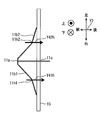
- FIG. 4 shows a schematic configuration of the guide member 11 used in the second embodiment as viewed from above. Moreover, the effect
- the guide member 11 passes through the first opening 11h1 formed by the through-hole penetrating the first guide blade 11b1 and the second guide blade 11b2. It has an opening 11h2 formed by a through hole.
- the first opening 11h1 and the second opening 11h2 are open on the surface of the guide member 11.
- a part of the cold air flows toward the rear of the guide member 11 through the first opening 11h1 and the second opening 11h2. If it does in this way, the warm air which raises the center part in the back of the guide member 11 as shown by arrow Y38, and the cool air which passed through opening part 11h1, 11h2 can be mixed.
- the increase in the weight of the guide member 11 and ventilation resistance can be relieved by providing opening part 11h1, 11h2.
- the openings 11h1 and 11h2 are formed in the guide blade portions 11b1 and 11b2, the cold air and the hot air can be mixed more efficiently.
- the first guide blade portion 11b1 and the second guide blade portion 11b2 form an acute angle at the top portion 11a, and the tip portion of the top portion 11a in the air flow direction is sharp.
- the shape in which the top part 11a is not sharp may be sufficient as long as the air flow can be branched in the left-right direction.
- the tip of the top portion 11a is flat.
- the first guide blade portion 11b1 and the second guide blade portion 11b2 have the first opening portion 11h1 and the second opening portion 11h2.
- the openings 11h1 and 11h2 may be grooves having a U-shaped cross section with one end opened.
- FIG. 7 A fourth embodiment will be described.
- the guide blade portions 11b1 and 11b2 are formed so that the cross-sectional shape is not a curved line but a broken line. Further, openings 11h1 and 11h2 are provided at the bent portions of the broken lines. Thereby, as shown by arrows Y41h and Y42h, air flows through the openings 11h1 and 11h2.
- the guide blade portions 11b1 and 11b2 extend from the top portion 11a toward the wall surface of the unit case 1 in a polygonal line shape. Therefore, the guide blade portions 11b1 and 11b2 are easy to manufacture, and the simulation of the wind flow by the guide blade portions 11b1 and 11b2 is also easy.
- the guide member 11 has a first wall portion 11c1 and a second wall portion 11c2 that extend in the front-rear direction Y2 and face each other in the left-right direction.
- the top part 11a has the 1st top part 11a1 and the 2nd top part 11a2 which were mutually spaced apart. Clearances are formed between the first top part 11a1 and the second top part 11a2 and between the first wall part 11c1 and the second wall part 11c2, respectively.
- the guide blade portions 11b1 and 11b2 extend from the pair of top portions 11a1 and 11a2 toward the left and right wall surfaces of the unit case 1, respectively.
- the first guide vane portion 11b1 extends from the first apex portion 11a1 to the first end portion 11d1 toward one side in the left-right direction
- the second guide vane portion 11b2 extends from the second apex portion 11a2 to the second end portion. Extends toward the other end in the left-right direction. According to this, it is possible to form a wind passage of an arbitrary size between the guide blade portions 11b1 and 11b2.
- the shape of the 1st guide blade part 11b1 and the 2nd guide blade part 11b2 does not need to be completely symmetrical.
- the heating heat exchanger 3 is not limited to the one through which hot water flows from the engine, but may be an electric heater or a heat pump condenser.
- the air mix door 6 that adjusts the air volume ratio between the hot air that passes through the heating heat exchanger 3 and the cold air that passes through the cooling heat exchanger 4 rotates around an axis instead of a sliding door if space permits. It may be a door having an air mix damper.
- the step portions 91 and 92 in the above embodiment extend in the left-right direction perpendicular to the front-rear direction Y2.
- the step portions 91 and 92 may be inclined with respect to the front-rear direction Y2 to gradually increase the cross-sectional area of the air passage in the unit case 1.
- the corner hot air passages 10a and 10c are formed by the step portions 91 and 92 and the second case portion 1b, and a part of the hot air that has passed through the heating heat exchanger 3 is indicated by arrows Y37 and Y39. As long as the corner warm air passages 10a and 10c can be raised along the step portions 91 and 92 as described above.
- the guide member 11 is composed of a single resin member, but each of the guide wing portions 11b1 and 11b2 may be independently fixed to the inner wall surface of the unit case 1. Moreover, you may abbreviate
- the fixed shaft 15 is not limited to a circular cross section, and any shaft that can reinforce the guide member 11 may be used.
- the fixing shaft 15 may be omitted as long as the tips of the guide blade portions 11b1 and 11b2 can be firmly fixed to the wall of the unit case 1. Further, in the case where the guide blade portions 11b1 and 11b2 are configured separately from the fixed shaft 15, if the guide blade portions 11b1 and 11b2 are brought into contact with a part of the fixed shaft 15, the vibration of the guide member is fixed. Can be absorbed by the shaft.
- the guide blade portions 11b1 and 11b2 of the guide member 11 and the fixed shaft 15 are integrally formed of the same material, but the fixed shaft 15 may be made of metal. Further, in FIG. 4, the guide blade portions 11 b 1 and 11 b 2 and the fixed shaft 15 may be separated. In that case, the claw portions integral with the guide blade portions 11b1 and 11b2 are fitted into the fitting holes formed in the fixed shaft 15, and the fixed shaft 15 and the guide blade portions 11b1 and 11b2 are fitted and fixed. You may fix by 11b3 and 11b4.
- the guide vane portions 11b1 and 11b2 can be easily replaced by the attachment and detachment at the fitting and fixing portions 11b3 and 11b4, so that the specification of the vehicle air conditioner can be easily changed.
- the surfaces of the guide blade portions 11b1 and 11b2 are desirably formed in a curved surface smoothly, but dimple-like irregularities may be formed in order to reduce the ventilation resistance or adjust the wind direction.
- the front-rear direction Y2 and the left-right direction are based on the traveling direction of the vehicle, and the up-down direction Y1 is the vertical direction.
- the mounting direction of the vehicle air conditioner is not limited to the direction of the above-described embodiment.
Landscapes
- Physics & Mathematics (AREA)
- Thermal Sciences (AREA)
- Engineering & Computer Science (AREA)
- Mechanical Engineering (AREA)
- Air-Conditioning For Vehicles (AREA)
Abstract
車両用空調装置は、ユニットケース(1)、冷房用熱交換器(4)、暖房用熱交換器(3)、エアミックスドア(6)、吹出口(21、7、81、82)、段部(91、92)、隅部温風通路(10a、10c)、および案内部材(11)を備える。段部は、ユニットケースのうち冷房用熱交換器の下流のユニットケースの壁部分に設けられ、ユニットケースのうち冷房用熱交換器を収納する左右方向の幅が狭い部分と、ユニットケースのうち冷房用熱交換器を収容する部分よりも左右方向の幅が広い部分とを連絡し、冷風通路よりもユニットケースの左右方向の幅を拡大する。隅部温風通路は、段部に隣接する左右方向の両側の隅に形成され暖房用熱交換器を通過した温風の一部が流れる。案内部材は、冷房用熱交換器の下流側に設けられ、冷房用熱交換器を通過した冷風を左右方向に分岐させて隅部温風通路に向けて案内する。
Description
本出願は、当該開示内容が参照によって本出願に組み込まれた、2014年11月21日に出願された日本特許出願2014-236860号を基にしている。
本開示は、冷却用熱交換器の空気流出面から流出した冷風と暖房用熱交換器の空気流出面から流出した温風とが混合されて、車室内に空調風として吹出される車両用空調装置に関するものである。
従来、特許文献1に記載の車両用空調装置がある。この車両用空調装置は、暖房用熱交換器を通過して流れる温風と暖房用熱交換器をバイパスして流れる冷風との風量割合を調整するエアミックス方式の車両用空調装置である。暖房用熱交換器の空気流出面の空気流れ方向の下流側には、空気流出面から温風が吹出す温風吹出空間の範囲内に複数のバッフル部材が暖房用熱交換器に近接して配置されている。このバッフル部材は、空気流出面と対向するケース壁面に向かって延びるように形成されている。夫々のバッフル部材は、冷風流れ方向の風上側部位が閉塞し、風下側部位が開口する樋形状を有している。バッフル部材は、暖房用熱交換器の空気流出面からの温風をケース壁面に向かって案内する。そして、バッフル部材の中を流れる温風が、バッフル部材間を流れる冷風の流れ方向と交差する方向に流れて、対向するケース壁面まで流れる。これにより、ケース壁面に到達する温風流れの比率を増大させ、冷風と温風との混合性を向上させている。
上記特許文献1の技術によると、複数のバッフル部材が必要となり、構成が複雑である。また、バッフル部材の延伸方向の寸法が大きくなる。従来は、ユニットケースの中には十分な大きさのエアミックス領域を設けることができるため、簡素なガイドや比較的小さいバッフル部材で温度制御の調整ができていた。
ところが、近年、ユニットケースに対しても小型軽量化が求められており、エアミックス領域も更に小型化せざるをえず、バッフル部材もより複雑で密度が高いものになってしまっている。
本開示は、上記点に鑑み、風を案内する部材の構成が単純であり、各吹き出し口に所望温度の風を容易な調整で供給できるように冷風と温風との混合性を制御させることができる車両用空調装置を提供することを目的とする。
従来技術として列挙された特許文献の記載内容は、この明細書に記載された技術的要素の説明として、参照によって導入ないし援用することができる。
本開示の車両用空調装置は、ユニットケース、冷房用熱交換器、暖房用熱交換器、エアミックスドア、吹出口、段部、隅部温風通路、および案内部材を備える。
ユニットケースは、空気が流れる空気通路を形成する。冷房用熱交換器は、ユニットケース内に形成された冷風通路を横切って配置され、空気を冷却する。暖房用熱交換器は、冷房用熱交換器の空気流れ方向における下流に配置され、空気を暖房する。エアミックスドアは、空気流れ方向において冷房用熱交換器と暖房用熱交換器との間に設けられ、ユニットケースの中において暖房用熱交換器をバイパスする冷風と暖房用熱交換器を通過した温風との風量割合を調整する。吹出口は、ユニットケースに設けられ、エアミックスドアにより温度調整された空調風を車室内の複数の部位に吹出す。
段部は、ユニットケースのうち冷房用熱交換器の下流のユニットケースの壁部分に設けられ、ユニットケースのうち冷房用熱交換器を収納する左右方向の幅が狭い部分と、ユニットケースのうち冷房用熱交換器を収容する部分よりも左右方向の幅が広い部分とを連絡し、冷風通路よりもユニットケースの左右方向の幅を拡大する。隅部温風通路は、段部に隣接する左右方向の両側の隅に形成され暖房用熱交換器を通過した温風の一部が流れる。案内部材は、冷房用熱交換器の下流側に設けられ、冷房用熱交換器を通過した冷風を左右方向に分岐させて隅部温風通路に向けて案内する。
この開示によれば、案内部材が、冷房用熱交換器の空気流出面を通過した冷風を分岐させ左右の段部に向けて案内する。段部によって、冷房用熱交換器より下流側における冷風通路よりも、左右幅の大きい温風通路を提供できる。この温風通路の左右端に位置する隅部温風通路を上昇する暖房用熱交換器からの温風の一部と、案内部材によって左右に分岐された冷房用熱交換器からの冷風と、をユニットケースの隅において混合させることができる。この隅部温風通路によって、冷風と温風との混合性が向上するため、必要なユニットケース内の容積を小型化することができる。また案内部材の形状寸法を調整することで複数の吹出口の夫々に所望の温度を供給することができる。
本開示についての上記目的およびその他の目的、特徴や利点は、添付の図面を参照しながら下記の詳細な記述により、より明確になる。
第1実施形態における車両用空調装置のユニットケース内の概略構成図である。
図1のユニットケース内の構成を示す斜視図である。
図1の案内部材の作用を説明する説明図である。
第2実施形態における案内部材の形状を示す概略構成図である。
図4の案内部材の作用を説明する説明図である。
第3実施形態における案内部材の形状を示す概略構成図である。
第4実施形態における案内部材の形状を示す概略構成図である。
第5実施形態における案内部材の形状を示す概略構成図である。
以下に、図面を参照しながら本開示を実施するための複数の形態を説明する。各形態において先行する形態で説明した事項に対応する部分には同一の参照符号を付して重複する説明を省略する場合がある。各形態において構成の一部を説明している場合は、構成の他の部分については先行して説明した他の形態を適用することができる。
各実施形態で具体的に組合せが可能であることを明示している部分同士の組合せばかりではなく、特に組合せに支障が生じなければ、明示していなくても実施形態同士を部分的に組合せることも可能である。
図面において、矢印Y1は車両の上下方向(鉛直方向)を示し、矢印Y2は車両の進行方向を基準とした前後方向を示している。上下方向における上方は車両の天井側、下方は車両の床側を指す。また、左右方向は車両の進行方向を基準とした左および右を指している。
(第1実施形態)
以下、第1実施形態について図1ないし図3を用いて詳細に説明する。図1は、本開示の車両用空調装置のユニットケース1の構成を概略的に示す。車室内に向かって空気が流れる空気通路を形成するユニットケース1は、空気通路の下流側に向けて図示しない送風機からの空調風を流す。
以下、第1実施形態について図1ないし図3を用いて詳細に説明する。図1は、本開示の車両用空調装置のユニットケース1の構成を概略的に示す。車室内に向かって空気が流れる空気通路を形成するユニットケース1は、空気通路の下流側に向けて図示しない送風機からの空調風を流す。
ユニットケース1の中には、空気を暖房する暖房用熱交換器3と、空気を冷却する冷房用熱交換器4とが、ユニットケース1内を流れる空気が暖房用熱交換器3と冷房用熱交換器4を通過するように配置されている。ユニットケース1の中において暖房用熱交換器3の上方を冷房用熱交換器4から矢印Y33、Y41、Y42、Y34に示すように冷風が流れる。冷房用熱交換器4は、冷房用熱交換器4の内部を流れる流体と冷房用熱交換器4を通過する空気とを熱交換し、当該空気が冷風として冷房用熱交換器4から流出する空気流出面4aを有している。
また、ユニットケース1の内部には、暖房用熱交換器3を通過してユニットケース1の上方に向かって温風が流れる温風通路が設けられている。この温風通路は、暖房用熱交換器3を通過した温風が上方に向かって流れる通路である。この温風通路は、ユニットケース1の中央部を暖房用熱交換器3から流出した温風が図3の矢印Y38に示すように流れる中央部温風通路と、ユニットケース1の両端部を暖房用熱交換器3から図3の矢印Y37、Y39に示すように流れる隅部温風通路10a、10cとからなる。隅部温風通路10a、10cは、左右方向に対向する一対の隅部温風通路である。これらの中央部温風通路と、隅部温風通路10a、10cとは、壁により区画された通路でなく、互いに連通する一つの通路である。なお、中央部温風通路や隅部温風通路10a、10cは、冷房用熱交換器で冷却された冷風と温風とが混合される混合領域でもある。
エアミックスドア6は周知のスライドドアであり、暖房用熱交換器3の上流側に設けられている。エアミックスドア6は、冷房用熱交換器4を通過した後、暖房用熱交換器3をバイパスする冷風と、冷房用熱交換器4を通過した後、暖房用熱交換器3を通過して温風となる冷風との風量割合を調整する。これにより、エアミックスドア6は、当該冷風と当該温風が混合した空調風の温度を調整する。この空調風を車室内の複数の部位に吹出す複数の吹出口7、81、82がユニットケース1に設けられ、上方に向かって開口している。
ユニットケース1には、冷房用熱交換器4の空気流出面4aの下流側における左右両側に壁部分を直角に膨出させる段部91、92が形成されている。ユニットケースの壁面は段部91、92の存在により寸法Waの段差を生じている。段部91、92は、空気通路の左右幅を増加させ、温風の一部が矢印Y37、Y39に示すように流れる隅部温風通路10a、10cを形成するスペースが確保される。なお図2は、ユニットケース1内の左右方向の一方のみを図示しているが、段部91、92は、ユニットケース1の左右方向の両側に対称的に存在する。
より具体的には、ユニットケース1は、冷房用熱交換器4を収納する左右方向の幅の狭いユニットケース部分(第1ケース部1a)と、第1ケース部1aの空気流れ方向の下流に位置し、第1ケース部1aよりも左右方向の幅が広いユニットケース部分(第2ケース部1b)と、を有している。段部91、92は、第1ケース部1aと第2ケース部1bとを連絡し、ユニットケース1の左右方向の幅を拡大する。換言すれば、段部91、92は、冷房用熱交換器4の下流において第1ケース部1aから左右方向に延びて第2ケース部1bに接続し、第2ケース部1bを第1ケース部1aよりも左右方向に拡大している。そして、第2ケース部1bおよび段部91によって隅部温風通路10aが画成され、第2ケース部1bおよび段部92によって隅部温風通路10bが画成される。
本実施形態では、段部91、92はユニットケース1の上下方向Y1における下端から案内部材11の近辺まで延びている。しかしながら、段部91、92は、ユニットケース1の上下方向Y1における下端の上方から案内部材11の近辺まで延びていても良く、温風を導くことができて、隅部温風通路を形成できれば良い。
案内部材11が、冷房用熱交換器4の空気流出面4aの下流側に設けられている。案内部材11は、空気流出面4aを通過した冷風のうち暖房用熱交換器3の方に向かわない冷風を図3の矢印Y33、Y41、Y42、Y34に示すように左右に分岐させる。そして、案内部材11は、左右の隅部温風通路10a、10cに向けて、冷房用熱交換器4からの冷風を案内している。この案内部材11は、上から見ると図1に示すように左右に広がった形状(カモメ形状)を有している。
この案内部材11で分岐された矢印Y33、Y34に示すように流れる冷風は、下方から上昇する隅部温風通路10a、10cの温風と衝突して混合され、空調風56となって上方のセンターフェイス吹出口7とサイドフェイス吹出口81、82に流れる。
図2に示すように、ユニットケース1の中の空気通路(第1ケース部1a)を横断するように冷房用熱交換器4を構成する蒸発器が設けられている。冷房用熱交換器4が設けられるこの空気通路は、換言すれば冷風通路である。この蒸発器の下流側には暖房用熱交換器3を構成するヒータコアが形成されている。暖房用熱交換器3の中ではエンジン冷却水となる温水が流れ、暖房用熱交換器3を通過する空気を加温する。暖房用熱交換器3によって加温された温風の一部は、図3の矢印Y37、Y39にて示すように、段部91、92に沿って隅部温風通路10a、10cを上昇する。
案内部材11は、第1案内翼部11b1、第2案内翼部11b2、頂部11a、および頂部11aに接続された壁部11cを有している。この壁部11cを貫通する固定軸15によって、ユニットケース1の壁面に案内部材11が固定されている。
センターフェイス吹出口7の前側には、フロントガラスに温風を吹き出すデフロスタ吹出口21が設けられている。デフロスタ吹出口21の中には、フロントガラスに吹き出される風の量を調整するデフロスタドア21dが軸と共に回転するように設けられている。なお、図1は、デフロスタ吹出口21の一部を破断して図示し、内部のデフロスタドア21dを仮想的に示している。
センターフェイス吹出口7の前側には、フロントガラスに温風を吹き出すデフロスタ吹出口21が設けられている。デフロスタ吹出口21の中には、フロントガラスに吹き出される風の量を調整するデフロスタドア21dが軸と共に回転するように設けられている。なお、図1は、デフロスタ吹出口21の一部を破断して図示し、内部のデフロスタドア21dを仮想的に示している。
また、フェイスドア23は、センターフェイス吹出口7を流れ出る空気流を制御するように回転軸22に連結されている。左右一対のサイドフェイスドア24は、回転軸22に設けられ、サイドフェイス吹出口81、82から流れ出る空気流を制御する。なお、図2には一方のサイドフェイスドア24だけが図示されており、他方のサイドフェイスドアはサイドフェイス吹出口82の中に位置している。
案内部材11は、頂部11aから左右方向における一方(図3の右側)に向かって延びる第1案内翼部11b1と、頂部11aから左右方向における他方(図3の左側)に向かって延びる第2案内翼部11b2とを有している。第1案内翼部11b1および第2案内翼部11b2は、冷房用熱交換器4から離れる方向(空気流れ下流)に向けて湾曲する(凸となる)ように延びている。第1案内翼部11b1および第2案内翼部11b2はそれぞれ、頂部11aとは左右方向の反対側の端部(後述する第1の端部11d1、第2の端部11d2)において固定軸15に結合されている。案内翼部11b1、11b2を固定軸15に結合することで、案内翼部11b1、11b2の振動を抑制することができる。
案内部材11は、固定軸15と共に一体の樹脂成型品で構成されており、案内部材11が固定軸15を介してユニットケース1の中の壁面(内壁面)に支持されている。ユニットケース1の壁面のうち暖房用熱交換器3の上部には、図2の矢印Y3にて示すように空調風を吹き出すフット吹出口26が設けられている。このように、フット吹出口26が形成されているから、乗員の足元に比較的暖かい風を矢印Y3に示すように吹出すことができる。この場合の空調風の量及び温度は、フットドア25の回転によって制御される。
第1実施形態の作用効果を説明する。第1実施形態においては、案内部材11が、冷房用熱交換器4の空気流出面4aを通過した冷風を左右に分岐させる。分岐された冷風は、隅部温風通路10a、10cに向けて矢印Y33、Y34に示すように案内される。
暖房用熱交換器3を通過した温風は、矢印Y37、Y39に示すように、段部91、92に沿って隅部温風通路10a、10c上昇する。この温風と、案内部材11によって左右に分岐された冷風とをユニットケース1内の左右方向の端部において混合させることができる。
かつ、空気を混合するために必要な前後方向Y2におけるユニットケース1の寸法を小さくできるのでユニットケース1の容積を小型化することができる。また案内部材11の形状及び寸法を調整することで、複数の吹出口21、7、81、82の夫々に所望の温度を供給することができる。
また、案内部材11は、頂部11a、第1案内翼部11b1、および第2案内翼部11b2を有している。頂部11aは、案内部材11のうち冷房用熱交換器4の空気流出面4aのもっとも近くに位置している。第1案内翼部11b1および第2案内翼部11b2は、この頂部11aから左右方向に分岐するように延びている。第1案内翼部11b1および第2案内翼部11b2はそれぞれ、冷房用熱交換器4から離れる方向に向けて湾曲している(凸になっている)。それ故、冷房用熱交換器4から流出した空気を隅部温風通路10a、10cに向けてスムーズに案内することができる。案内部材11は、単純な構成を有しつつ、各吹出口に所望温度の空調風を供給できるように冷風と温風との混合割合を調整することができる。また、案内部材11は、上下方向Y1に延びており、冷風を上下方向Y1に分岐させるとともに、左右方向に拡散させ、後方の温風通路10bに向けて案内する。
さらに、第1案内翼部11b1は、頂部11aから第1の端部11d1にかけて左右方向における一方に向かって延びている。第2案内翼部11b2は、頂部11aから第2の端部11d2にかけて左右方向における他方に向かって延びている。第1の端部11d1および第2の端部11d2のそれぞれと、空気流出面4aとの間の左右方向における距離は、隅部温風通路10a、10cのそれぞれと空気流出面4aとの間の左右方向における距離よりも大きくなっている。換言すれば、案内部材11の左右方向の両端部11d1、11d2が、空気流れ方向において隅部温風通路10a、10cの下流に位置している。これにより、冷房用熱交換器4から流出した冷風を、第1案内翼部11b1及び第2案内翼部11b2によって、確実に隅部温風通路10a、10cに導くことができる。
また、頂部11aと空気流出面4aとの間の左右方向の距離は、空気流出面4aと一対の隅部温風通路10a、10cのそれぞれとの間の距離よりも短くなっている。これにより、冷房用熱交換器4から流出した冷風を、第1案内翼部11b1及び第2案内翼部11b2によって、更に確実に隅部温風通路10a、10cに導くことができる。
隅部温風通路10a、10cは、第2ケース部1bと段部91、92によって画成されており、空気流れ方向において段部91、92の下流に位置している。ユニットケース1の左右方向の幅が段部91、92によって拡大されているため、冷房用熱交換器4により冷却されて第1ケース部1aを流れる冷風の風速は、当該冷風が第2ケース部1bに流入すると減速する。従って、暖房用熱交換器3によって加熱された温風を、段部91、92に沿って隅部温風通路10a、10cを容易に上昇させることができる。
矢印Y37、Y39に示すように隅部温風通路10a、10cを通る温風は、幅寸法Waの大きさを持つ段部91、92に沿って上昇する。幅寸法Waは、左右方向における段部91、92の長さである。隅部温風通路10a、10cを流れる矢印Y37、Y39の温風は、デフロスタ吹出口21等へ流れる。案内部材11は、センターフェイス吹出口7と、サイドフェイス吹出口81、82に流れる冷風の左右方向の分布を調整すると共に、デフロスタ吹出口21へ流れる冷風と温風の風量を調整する。段部91、92の幅寸法Waと、案内部材11の広がり寸法Wbと、案内部材11の高さ寸法Wcとがこれらの調整に関与する。広がり寸法Wbとは、第1案内翼部11b1の第1の端部11d1と第2案内翼部11b2の第2の端部11d2との間の左右方向における長さである。高さ寸法Wcとは、上下方向Y1における案内部材11の長さである。幅寸法Wa、広がり寸法Wbおよび高さ寸法Wcを増減させることで、吹出口7、81、82から車室内に流入する空調風が所望の温度になるように調整することができる。
案内部材11の下部において、図3において矢印Y35、Y36に示すように左右方向に分岐した冷風が、矢印Y37、Y39に示すように隅部温風通路10a、10cを上昇する温風の一部と混合される。更に、案内部材11の中央部を通る矢印Y38にて示す温風と矢印Y41h、Y42hにて示す冷風とが混合領域(温風通路10b)で混合される。混合されることで適度な温度となった空気は矢印Y31、Y32に示すように流れ、空調風56として、センターフェイス吹出口7、サイドフェイス吹出口81、82から車室内に吹出される。
センターフェイス吹出口7とサイドフェイス吹出口81、82との間のフェイス吹出温度のばらつきを低減する場合は、案内部材11の高さ寸法Wcを増加させ、段部91、92の幅寸法Waを減らすと良い。
例えば、上下方向Y1に並ぶフェイス吹出口とフット吹出口の双方から空気を吹出すバイレベルモードを持つ車両用空調装置の場合のフェイス吹出口とフット吹出口との間の温度差、又は、フット吹出口26とデフロスタ吹出口21との間の温度差を拡大する必要がある。この場合は、段部91、92の幅寸法Waと案内部材11の高さ寸法Wcとを減少させ、案内部材11の広がり寸法Wbを増加させると良い。このように寸法Wa、Wb、Wcを調整することで、狙いの温度ばらつきと上下方向Y1に並ぶ2つの吹出口から流出する空気の温度の間の温度差を所望のように成立させることができる。
なお、案内部材11の案内翼部11b1、11b2が湾曲しているのは、中央部の流速の高い冷風を左右方向に分岐させる際に通風抵抗の影響を最小化するためである。上記寸法Wa、Wb、Wcは、冷風が案内部材11に衝突するときの風量や角度、案内部材11に導かれてユニットケース1内の空気通路に流出するときの方向、および各吹出口21、7、81、82の風量に基づいて設定する必要がある。そのため、実際の設計では、最初に図1のような位置に案内部材11を設定し、数値計算やシミュレーションによって最終的な案内部材11の形状と寸法とを決める。
具体例として、ユニットケース1の通路幅WUが165mm、段部91、92の幅寸法Waが25mm、案内部材11の広がり寸法Wbが160mm、案内部材11の高さ寸法Wcが30mmである。これにより、バイレベルモードにおけるフェイス吹出口から流出する空気の温度とフット吹出口から流出する空気の温度との間の温度差を21.2℃とし、フット吹出口26から流出する空気の温度とデフロスタ吹出口21から流出する空気の温度との間の温度差を12.4℃とすることができる。
また、案内部材11は、頂部11aに結合された壁部11cを有し、この壁部11cを貫通する固定軸15によってユニットケース1の壁面に固定されている。これによれば、固定軸15によって強固に案内部材11をユニットケース1の中央部に位置するように取り付けることができる。
(第2実施形態)
次に、第2実施形態について説明する。図4は、第2実施形態で用いる案内部材11を上方から見た概略構成を示す。また、図5を用いて、図4の案内部材11の作用を説明する。
次に、第2実施形態について説明する。図4は、第2実施形態で用いる案内部材11を上方から見た概略構成を示す。また、図5を用いて、図4の案内部材11の作用を説明する。
図4および5に示すように、本実施形態では、案内部材11は、第1案内翼部11b1を貫通する貫通孔によって形成された第1開口部11h1と、第2案内翼部11b2を貫通する貫通穴によって形成された開口部11h2を有している。第1開口部11h1と第2開口部11h2は、案内部材11の表面において開口している。矢印Y41h、Y42hに示すように、冷風の一部が、第1開口部11h1および第2開口部11h2を通って案内部材11の後方に向かって流れる。このようにすれば、案内部材11の後方における中央部を矢印Y38に示すように上昇する温風と、開口部11h1、11h2を通過した冷風とを混合することができる。また、開口部11h1、11h2を設けることで案内部材11の重量及び通風抵抗の増加を緩和できる。このように、案内翼部11b1、11b2に開口部11h1、11h2が形成されていることにより、冷風と温風を更に効率よく混合することができる。
(第3実施形態)
次に、第3実施形態について説明する。第1実施形態においては、第1案内翼部11b1と第2案内翼部11b2が頂部11aにおいて鋭角をなし、頂部11aの空気流れ方向における先端部が尖っている。しかしながら、空気の流れを左右方向に分岐できればよく頂部11aが尖っていない形状でも良い。例えば、図6に示すように、本実施形態では、頂部11aの先端部は平坦になっている。本実施形態においても、第2実施形態と同様に、第1案内翼部11b1および第2案内翼部11b2が第1開口部11h1および第2開口部11h2を有している。矢印Y41h、Y42hに示すように、冷風の一部が第1開口部11h1および第2開口部11h2を通って案内部材11の前後方向Y2における後方に向かって流れる。なお、開口部11h1、11h2は、一端が開放されてU字形の断面を有する溝であっても良い。
次に、第3実施形態について説明する。第1実施形態においては、第1案内翼部11b1と第2案内翼部11b2が頂部11aにおいて鋭角をなし、頂部11aの空気流れ方向における先端部が尖っている。しかしながら、空気の流れを左右方向に分岐できればよく頂部11aが尖っていない形状でも良い。例えば、図6に示すように、本実施形態では、頂部11aの先端部は平坦になっている。本実施形態においても、第2実施形態と同様に、第1案内翼部11b1および第2案内翼部11b2が第1開口部11h1および第2開口部11h2を有している。矢印Y41h、Y42hに示すように、冷風の一部が第1開口部11h1および第2開口部11h2を通って案内部材11の前後方向Y2における後方に向かって流れる。なお、開口部11h1、11h2は、一端が開放されてU字形の断面を有する溝であっても良い。
(第4実施形態)
第4実施形態について説明する。図7において案内翼部11b1、11b2は、断面形状が曲線状でなく、折れ線状となるように形成されている。また折れ線の折れ曲がり部分に開口部11h1、11h2を設けている。これにより、矢印Y41h、Y42hに示すように、開口部11h1、11h2を通って空気が流れる。この第4実施形態においては、案内翼部11b1、11b2が、頂部11aから折れ線状にユニットケース1の壁面に向かって延在している。よって案内翼部11b1、11b2が製作しやすく、案内翼部11b1、11b2による風流れのシミュレーションも容易である。
第4実施形態について説明する。図7において案内翼部11b1、11b2は、断面形状が曲線状でなく、折れ線状となるように形成されている。また折れ線の折れ曲がり部分に開口部11h1、11h2を設けている。これにより、矢印Y41h、Y42hに示すように、開口部11h1、11h2を通って空気が流れる。この第4実施形態においては、案内翼部11b1、11b2が、頂部11aから折れ線状にユニットケース1の壁面に向かって延在している。よって案内翼部11b1、11b2が製作しやすく、案内翼部11b1、11b2による風流れのシミュレーションも容易である。
(第5実施形態)
次に、第5実施形態について説明する。図8に示すように、案内部材11は、前後方向Y2に伸びるとともに左右方向に対向する第1壁部11c1および第2壁部11c2を有している。また、頂部11aは、互いに離間した第1頂部11a1および第2頂部11a2を有している。第1頂部11a1と第2頂部11a2との間、及び第1壁部11c1と第2壁部11c2との間にはそれぞれ隙間が形成されており、矢印Y41hに示すようにこれらの隙間を冷風が流れる。この第5実施形態においては、案内翼部11b1、11b2は、一対の頂部11a1、11a2の夫々からユニットケース1の左右両側の壁面に向かって延在している。具体的に、第1案内翼部11b1は、第1頂部11a1から第1の端部11d1にかけて左右方向における一方に向かって延びており、第2案内翼部11b2は、第2頂部11a2から第2の端部11d2にかけて左右方向における他方に向かって延びている。これによれば、案内翼部11b1、11b2相互間に任意の大きさの風の通路を形成することができる。なお、第1案内翼部11b1および第2案内翼部11b2の形状は、完全に対称でなくても良い。
次に、第5実施形態について説明する。図8に示すように、案内部材11は、前後方向Y2に伸びるとともに左右方向に対向する第1壁部11c1および第2壁部11c2を有している。また、頂部11aは、互いに離間した第1頂部11a1および第2頂部11a2を有している。第1頂部11a1と第2頂部11a2との間、及び第1壁部11c1と第2壁部11c2との間にはそれぞれ隙間が形成されており、矢印Y41hに示すようにこれらの隙間を冷風が流れる。この第5実施形態においては、案内翼部11b1、11b2は、一対の頂部11a1、11a2の夫々からユニットケース1の左右両側の壁面に向かって延在している。具体的に、第1案内翼部11b1は、第1頂部11a1から第1の端部11d1にかけて左右方向における一方に向かって延びており、第2案内翼部11b2は、第2頂部11a2から第2の端部11d2にかけて左右方向における他方に向かって延びている。これによれば、案内翼部11b1、11b2相互間に任意の大きさの風の通路を形成することができる。なお、第1案内翼部11b1および第2案内翼部11b2の形状は、完全に対称でなくても良い。
(他の実施形態)
上記の実施形態では、本開示の好ましい実施形態について説明したが、本開示は上記した実施形態に何ら制限されることなく、本開示の主旨を逸脱しない範囲において種々変形して実施することが可能である。上記実施形態の構造は、あくまで例示であって、本開示の範囲はこれらの記載の範囲に限定されるものではない。本開示の範囲は、特許請求の範囲の記載によって示され、更に、特許請求の範囲の記載と均等の意味及び範囲内での全ての変更を含むものである。
上記の実施形態では、本開示の好ましい実施形態について説明したが、本開示は上記した実施形態に何ら制限されることなく、本開示の主旨を逸脱しない範囲において種々変形して実施することが可能である。上記実施形態の構造は、あくまで例示であって、本開示の範囲はこれらの記載の範囲に限定されるものではない。本開示の範囲は、特許請求の範囲の記載によって示され、更に、特許請求の範囲の記載と均等の意味及び範囲内での全ての変更を含むものである。
暖房用熱交換器3は、エンジンからの温水が流れるものに限らず、電気ヒータ、又は、ヒートポンプの凝縮器であっても良い。暖房用熱交換器3を通過する温風と冷房用熱交換器4を通過する冷風との風量割合を調整するエアミックスドア6は、スペースが許せば、スライドドアでなく軸周りを回動するエアミックスダンパを有するドアであっても良い。
上記実施形態における段部91、92は、前後方向Y2と垂直な左右方向に延びている。しかしながら、段部91、92は、前後方向Y2に対して傾斜して、ユニットケース1内の空気通路の断面積を徐々に拡大しても良い。要は、段部91、92と第2ケース部1bによって隅部温風通路10a、10cが形成されて、暖房用熱交換器3を通過した温風の一部が、矢印Y37、Y39に示すように段部91、92に沿って隅部温風通路10a、10cを上昇することができれば良い。
案内部材11は、単一の樹脂部材で構成したが、案内翼部11b1および11b2の夫々が独立してユニットケース1の内壁面に固定されていても良い。また、壁部11cは省略しても良い。更に、固定軸15は断面円形に限らず、案内部材11を補強できるものであれば良い。強固に案内翼部11b1、11b2の先端をユニットケース1の壁に固定できれば、固定軸15を省略しても良い。また、案内翼部11b1、11b2が、固定軸15と別体に構成されている場合において、案内翼部11b1、11b2を、固定軸15の一部に接触させれば、案内部材の振動を固定軸によって吸収することができる。
更に、上述した実施形態では案内部材11の案内翼部11b1、11b2と固定軸15とを同一材料で一体成型したが、固定軸15は金属製であっても良い。更には、図4において、案内翼部11b1、11b2と固定軸15とを別体としてもよい。その場合は、固定軸15に形成した嵌合孔の中に、案内翼部11b1、11b2と一体の爪部を嵌合して、固定軸15と案内翼部11b1、11b2とを嵌合固定部11b3、11b4にて固定しても良い。
この場合は、嵌合固定部11b3、11b4での脱着により、案内翼部11b1、11b2の取り換えが容易であるため、車両用空調装置の仕様変更に対応しやすい。案内翼部11b1、11b2の表面は曲面状に滑らかに形成することが望ましいが、通風抵抗を小さくしたり風向きを調整したりするために、ディンプル状の凹凸を形成しても良い。
また、上述した各実施形態において、前後方向Y2および左右方向を車両の進行方向を基準とし、上下方向Y1を鉛直方向としている。しかしながら、本開示の効果が得られるのであれば、車両用空調装置の搭載方向は上述した実施形態の方向に限定されない。
Claims (18)
- 空気が流れる空気通路を形成するユニットケース(1)と、
前記ユニットケース(1)内に形成された冷風通路を横切って配置され、空気を冷却する冷房用熱交換器(4)と、
前記冷房用熱交換器(4)の空気流れ方向における下流に配置され、空気を暖房する暖房用熱交換器(3)と、
前記空気流れ方向において前記冷房用熱交換器(4)と前記暖房用熱交換器(3)との間に設けられ、前記ユニットケース(1)の中において前記暖房用熱交換器(3)をバイパスする冷風と前記暖房用熱交換器(3)を通過した温風との風量割合を調整するエアミックスドア(6)と、
前記ユニットケース(1)に設けられ、前記エアミックスドア(6)により温度調整された空調風を車室内の複数の部位に吹出す吹出口(21、7、81、82)と、
前記ユニットケース(1)のうち前記冷房用熱交換器(4)の下流の前記ユニットケース(1)の壁部分に設けられ、前記ユニットケース(1)のうち前記冷房用熱交換器(4)を収納する左右方向の幅が狭い部分と、前記ユニットケース(1)のうち前記冷房用熱交換器(4)を収容する部分よりも前記左右方向の幅が広い部分とを連絡し、前記冷風通路よりもユニットケース(1)の左右方向の幅を拡大する段部(91、92)と、
前記段部(91、92)に隣接する前記左右方向の両側の隅に形成され前記暖房用熱交換器(3)を通過した温風の一部が流れる隅部温風通路(10a、10c)と、
前記冷房用熱交換器(4)の下流側に設けられ、前記冷房用熱交換器(4)を通過した前記冷風を前記左右方向に分岐させて前記隅部温風通路(10a、10c)に向けて案内する案内部材(11)と、を備える車両用空調装置。 - 前記案内部材(11)は、前記冷房用熱交換器(4)側に設けられた頂部(11a)と、この頂部(11a)から前記左右方向に延在する案内翼部(11b1、11b2)とを有する請求項1に記載の車両用空調装置。
- 前記案内部材(11)は、前記頂部(11a)に結合された壁部(11c)を有し、この壁部(11c)を貫通する固定軸(15)によって前記ユニットケース(1)の壁面に支持されている請求項2に記載の車両用空調装置。
- 前記案内翼部(11b1、11b2)は、前記固定軸(15)と一体に構成されている請求項3に記載の車両用空調装置。
- 前記案内部材(11)は、前記固定軸(15)と共に一体の樹脂成型品で構成されている請求項4に記載の車両用空調装置。
- 前記案内翼部(11b1、11b2)は、前記固定軸(15)と別体に構成されて、前記固定軸(15)に接触する請求項3に記載の車両用空調装置。
- 前記案内翼部(11b1、11b2)が、前記頂部(11a)から曲線状に前記ユニットケース(1)の壁面に向かって延在している請求項2から6のいずれか一項に記載の車両用空調装置。
- 前記案内翼部(11b1、11b2)が、前記頂部(11a)から折れ線状に前記ユニットケース(1)の壁面に向かって延在している請求項2から6のいずれか一項に記載の車両用空調装置。
- 前記案内翼部(11b1、11b2)は、前記冷房用熱交換器(4)から離れる方向に向けて凸となっている請求項7または8に記載の車両用空調装置。
- 前記頂部は、一対の頂部(11a1、11a2)から成り、前記案内翼部(11b1、11b2)は、前記一対の頂部(11a1、11a2)の夫々から前記ユニットケース(1)の前記左右方向の両側の壁面に向かって延在している請求項2から9のいずれか一項に記載の車両用空調装置。
- 前記案内翼部(11b1、11b2)は、前記冷風が貫通して流れる開口部(11h1、11h2)を有している請求項2から10のいずれか一項に記載の車両用空調装置。
- 前記案内部材(11)は上下方向(Y1)に延び、前記冷風を前記上下方向(Y1)に分岐させる請求項1から11のいずれか一項に記載の車両用空調装置。
- 前記隅部温風通路(10a、10c)は、前記空気流れ方向において前記段部(91、92)の下流に位置している請求項1から12のいずれか一項に記載の車両用空調装置。
- 前記冷房用熱交換器(4)は、前記冷風が流出する空気流出面(4a)を有し、
前記隅部温風通路(10a、10c)は、前記ユニットケース(1)において、前記左右方向に離間して設けられ、
前記案内部材(11)は、前記左右方向において前記隅部温風通路の間に設けられ、
前記案内翼部(11b1、11b2)は、
前記頂部(11a)から第1の端部(11d1)にかけて前記左右方向における一方に向かって延びる第1案内翼部(11b1)と、
前記頂部(11a)から第2の端部(11d2)にかけて前記左右方向における他方に向かって延びる第2案内翼部(11b2)と、を有しており、
前記第1の端部(11d1)および前記第2の端部(11d2)のそれぞれと、前記空気流出面(4a)との間の前記左右方向における距離は、前記隅部温風通路のそれぞれと前記空気流出面(4a)との間の前記左右方向における距離よりも大きくなっている請求項2から13のいずれか一項に記載の車両用空調装置。 - 前記頂部(11a)と前記空気流出面(4a)との間の前記左右方向における距離は、前記隅部温風通路のそれぞれと前記空気流出面(4a)との間の前記左右方向における距離よりも小さくなっている請求項14に記載の車両用空調装置。
- 前記ユニットケース(1)における前記暖房用熱交換器(3)の前記空気流れ方向の下流には、乗員の足元に前記空調風を吹出すフット吹出口(26)が形成されている請求項1から15のいずれか一項に記載の車両用空調装置。
- 前記ユニットケース(1)における前記段部(91、92)の上方には、前記車室内に前記空調風を送風するセンターフェイス吹出口(7)と、サイドフェイス吹出口(81、82)と、デフロスタ吹出口(21)と、が開口している請求項1から16のいずれか一項に記載の車両用空調装置。
- 空気が流れる空気通路が内部に形成され、第1ケース部(1a)、および前記第1ケース部(1a)の空気流れ方向の下流に位置して前記第1ケース部(1a)よりも左右方向に拡大した第2ケース部(1b)を有するユニットケース(1)と、
前記第1ケース部(1a)内に配置され、空気を冷却する冷房用熱交換器(4)と、
前記空気流れ方向において前記冷房用熱交換器(4)の下流に配置され、空気を暖房する暖房用熱交換器(3)と、
前記冷房用熱交換器(4)によって冷却されて前記暖房用熱交換器(3)をバイパスする冷風と、前記暖房用熱交換器(3)を通過して暖房される温風との風量割合を調整するエアミックスドア(6)と、
前記ユニットケース(1)に設けられ、前記冷風と前記温風とが混合した空調風を車室内の複数の部位に吹出す吹出口(21、7、81、82)と、
前記冷房用熱交換器(4)の下流において前記第1ケース部(1a)および前記第2ケース部(1b)を接続する段部(91、92)と、
前記第2ケース部(1b)および前記段部(91、92)によって画成され、前記温風の一部が流れる隅部温風通路(10a、10c)と、
前記冷房用熱交換器(4)の下流に設けられ、前記冷風を前記左右方向に分岐させて前記隅部温風通路(10a、10c)に向けて案内する案内部材(11)と、を備える車両用空調装置。
Priority Applications (2)
| Application Number | Priority Date | Filing Date | Title |
|---|---|---|---|
| DE112015005239.9T DE112015005239T5 (de) | 2014-11-21 | 2015-11-16 | Klimatisierungsvorrichtung für Fahrzeug |
| CN201580029008.3A CN106414124B (zh) | 2014-11-21 | 2015-11-16 | 车辆用空调装置 |
Applications Claiming Priority (2)
| Application Number | Priority Date | Filing Date | Title |
|---|---|---|---|
| JP2014-236860 | 2014-11-21 | ||
| JP2014236860A JP6287777B2 (ja) | 2014-11-21 | 2014-11-21 | 車両用空調装置 |
Publications (1)
| Publication Number | Publication Date |
|---|---|
| WO2016079977A1 true WO2016079977A1 (ja) | 2016-05-26 |
Family
ID=56013550
Family Applications (1)
| Application Number | Title | Priority Date | Filing Date |
|---|---|---|---|
| PCT/JP2015/005702 Ceased WO2016079977A1 (ja) | 2014-11-21 | 2015-11-16 | 車両用空調装置 |
Country Status (4)
| Country | Link |
|---|---|
| JP (1) | JP6287777B2 (ja) |
| CN (1) | CN106414124B (ja) |
| DE (1) | DE112015005239T5 (ja) |
| WO (1) | WO2016079977A1 (ja) |
Cited By (2)
| Publication number | Priority date | Publication date | Assignee | Title |
|---|---|---|---|---|
| CN115923433A (zh) * | 2021-08-20 | 2023-04-07 | 马勒国际有限公司 | 低声排放的散流器以及包括该散流器的空调系统 |
| US20230182529A1 (en) * | 2020-05-13 | 2023-06-15 | Truma Geraetetechnik Gmbh & Co.Kg | Air-conditioning system |
Families Citing this family (2)
| Publication number | Priority date | Publication date | Assignee | Title |
|---|---|---|---|---|
| JP6934274B2 (ja) * | 2017-06-28 | 2021-09-15 | ダイハツ工業株式会社 | 車両用空調装置 |
| JP2021110269A (ja) * | 2020-01-08 | 2021-08-02 | 本田技研工業株式会社 | 車両における蓄熱器付近の冷媒用配管のレイアウト構造 |
Citations (4)
| Publication number | Priority date | Publication date | Assignee | Title |
|---|---|---|---|---|
| JPS5814010U (ja) * | 1981-07-20 | 1983-01-28 | カルソニックカンセイ株式会社 | 自動車用空気調和装置 |
| JPH10236134A (ja) * | 1996-06-17 | 1998-09-08 | Denso Corp | 車両用空調装置 |
| JP2001150926A (ja) * | 1999-11-24 | 2001-06-05 | Zexel Valeo Climate Control Corp | 自動車用空調装置 |
| JP2007526170A (ja) * | 2004-03-03 | 2007-09-13 | ベール フランス ルファッシェ エス・アー・エス | 自動車用の空調装置 |
Family Cites Families (2)
| Publication number | Priority date | Publication date | Assignee | Title |
|---|---|---|---|---|
| JP2005112297A (ja) * | 2003-10-10 | 2005-04-28 | Denso Corp | 車両用空調装置 |
| JP4464427B2 (ja) * | 2007-06-28 | 2010-05-19 | カルソニックカンセイ株式会社 | 自動車用空調装置 |
-
2014
- 2014-11-21 JP JP2014236860A patent/JP6287777B2/ja not_active Expired - Fee Related
-
2015
- 2015-11-16 DE DE112015005239.9T patent/DE112015005239T5/de not_active Ceased
- 2015-11-16 WO PCT/JP2015/005702 patent/WO2016079977A1/ja not_active Ceased
- 2015-11-16 CN CN201580029008.3A patent/CN106414124B/zh not_active Expired - Fee Related
Patent Citations (4)
| Publication number | Priority date | Publication date | Assignee | Title |
|---|---|---|---|---|
| JPS5814010U (ja) * | 1981-07-20 | 1983-01-28 | カルソニックカンセイ株式会社 | 自動車用空気調和装置 |
| JPH10236134A (ja) * | 1996-06-17 | 1998-09-08 | Denso Corp | 車両用空調装置 |
| JP2001150926A (ja) * | 1999-11-24 | 2001-06-05 | Zexel Valeo Climate Control Corp | 自動車用空調装置 |
| JP2007526170A (ja) * | 2004-03-03 | 2007-09-13 | ベール フランス ルファッシェ エス・アー・エス | 自動車用の空調装置 |
Cited By (3)
| Publication number | Priority date | Publication date | Assignee | Title |
|---|---|---|---|---|
| US20230182529A1 (en) * | 2020-05-13 | 2023-06-15 | Truma Geraetetechnik Gmbh & Co.Kg | Air-conditioning system |
| CN115923433A (zh) * | 2021-08-20 | 2023-04-07 | 马勒国际有限公司 | 低声排放的散流器以及包括该散流器的空调系统 |
| US12539740B2 (en) | 2021-08-20 | 2026-02-03 | Mahle International Gmbh | Low sound emission flow diffusor as well as air conditioning system comprising the same |
Also Published As
| Publication number | Publication date |
|---|---|
| JP6287777B2 (ja) | 2018-03-07 |
| JP2016097823A (ja) | 2016-05-30 |
| CN106414124B (zh) | 2018-12-07 |
| DE112015005239T5 (de) | 2017-09-28 |
| CN106414124A (zh) | 2017-02-15 |
Similar Documents
| Publication | Publication Date | Title |
|---|---|---|
| JP4883080B2 (ja) | 車両用空調装置 | |
| JP4971963B2 (ja) | 自動車用空気調和装置 | |
| JP6269561B2 (ja) | 車両用空調ユニット | |
| KR101928334B1 (ko) | 3 또는 4 구역 자동차 공기 조절 설비의 제3 구역 및/또는 제4 구역을 위한 공기 분배 시스템 | |
| US20090215379A1 (en) | Vehicular air-conditioning system | |
| JP2017094753A (ja) | 車両用空調ユニット | |
| WO2016079977A1 (ja) | 車両用空調装置 | |
| WO2012157183A1 (ja) | 車両用空調装置 | |
| KR102182344B1 (ko) | 차량용 공조장치 | |
| KR102056123B1 (ko) | 자동차 공조 시스템용 공기 분배 어셈블리 | |
| WO2014058009A1 (ja) | 車両用空調装置 | |
| CN112292274B (zh) | 车辆用空调装置 | |
| JP6371533B2 (ja) | 車両用空調装置 | |
| US20240174046A1 (en) | Device for thermal treatment of air for a vehicle with improved temperature management | |
| EP3199391B1 (en) | Vehicle air-conditioning apparatus | |
| JP2018188070A (ja) | 車両用空調装置 | |
| JP6208686B2 (ja) | 車両用空調装置のドア保持構造及びこれを備えた車両用空調装置 | |
| JP2014148186A (ja) | 空調ユニット用ドア構造および空調ユニット | |
| JP5398170B2 (ja) | 車両用空調装置 | |
| JP6235271B2 (ja) | 車両用空調ユニット | |
| JP6783082B2 (ja) | 空気調和ユニット及び車両用空気調和装置 | |
| JP2017013732A (ja) | 車両用空調装置 | |
| JP2020175765A (ja) | 車両用空調装置 | |
| WO2013047562A1 (ja) | 空調用ダクト | |
| JP2012232662A (ja) | 空気調和ユニットおよび車両用空気調和装置 |
Legal Events
| Date | Code | Title | Description |
|---|---|---|---|
| 121 | Ep: the epo has been informed by wipo that ep was designated in this application |
Ref document number: 15861209 Country of ref document: EP Kind code of ref document: A1 |
|
| WWE | Wipo information: entry into national phase |
Ref document number: 112015005239 Country of ref document: DE |
|
| 122 | Ep: pct application non-entry in european phase |
Ref document number: 15861209 Country of ref document: EP Kind code of ref document: A1 |