WO2016076095A1 - Method for assembling wire harness, interference suppressing member, and wire harness assembly structure - Google Patents
Method for assembling wire harness, interference suppressing member, and wire harness assembly structure Download PDFInfo
- Publication number
- WO2016076095A1 WO2016076095A1 PCT/JP2015/079781 JP2015079781W WO2016076095A1 WO 2016076095 A1 WO2016076095 A1 WO 2016076095A1 JP 2015079781 W JP2015079781 W JP 2015079781W WO 2016076095 A1 WO2016076095 A1 WO 2016076095A1
- Authority
- WO
- WIPO (PCT)
- Prior art keywords
- interference suppression
- reinforcement
- suppression member
- wire harness
- bracket
- Prior art date
Links
- 238000000034 method Methods 0.000 title claims abstract description 43
- 230000002787 reinforcement Effects 0.000 claims abstract description 147
- 230000001629 suppression Effects 0.000 claims description 160
- 239000000463 material Substances 0.000 claims description 34
- 238000005452 bending Methods 0.000 claims description 13
- 230000002093 peripheral effect Effects 0.000 claims description 10
- 230000004048 modification Effects 0.000 description 10
- 238000012986 modification Methods 0.000 description 10
- 239000011347 resin Substances 0.000 description 7
- 229920005989 resin Polymers 0.000 description 7
- 230000001681 protective effect Effects 0.000 description 3
- 238000003466 welding Methods 0.000 description 3
- 239000000853 adhesive Substances 0.000 description 2
- 230000001070 adhesive effect Effects 0.000 description 2
- 238000010586 diagram Methods 0.000 description 2
- 238000001125 extrusion Methods 0.000 description 2
- 239000000123 paper Substances 0.000 description 2
- 230000000149 penetrating effect Effects 0.000 description 2
- 238000004804 winding Methods 0.000 description 2
- 238000007765 extrusion coating Methods 0.000 description 1
- 238000003780 insertion Methods 0.000 description 1
- 230000037431 insertion Effects 0.000 description 1
- 238000005304 joining Methods 0.000 description 1
- 238000004519 manufacturing process Methods 0.000 description 1
- 239000002184 metal Substances 0.000 description 1
- 238000000465 moulding Methods 0.000 description 1
- 239000004745 nonwoven fabric Substances 0.000 description 1
- 239000013307 optical fiber Substances 0.000 description 1
- 230000002940 repellent Effects 0.000 description 1
- 239000005871 repellent Substances 0.000 description 1
- 239000000758 substrate Substances 0.000 description 1
- XLYOFNOQVPJJNP-UHFFFAOYSA-N water Substances O XLYOFNOQVPJJNP-UHFFFAOYSA-N 0.000 description 1
Images


Classifications
-
- B—PERFORMING OPERATIONS; TRANSPORTING
- B60—VEHICLES IN GENERAL
- B60R—VEHICLES, VEHICLE FITTINGS, OR VEHICLE PARTS, NOT OTHERWISE PROVIDED FOR
- B60R16/00—Electric or fluid circuits specially adapted for vehicles and not otherwise provided for; Arrangement of elements of electric or fluid circuits specially adapted for vehicles and not otherwise provided for
- B60R16/02—Electric or fluid circuits specially adapted for vehicles and not otherwise provided for; Arrangement of elements of electric or fluid circuits specially adapted for vehicles and not otherwise provided for electric constitutive elements
- B60R16/0207—Wire harnesses
- B60R16/0215—Protecting, fastening and routing means therefor
-
- F—MECHANICAL ENGINEERING; LIGHTING; HEATING; WEAPONS; BLASTING
- F16—ENGINEERING ELEMENTS AND UNITS; GENERAL MEASURES FOR PRODUCING AND MAINTAINING EFFECTIVE FUNCTIONING OF MACHINES OR INSTALLATIONS; THERMAL INSULATION IN GENERAL
- F16L—PIPES; JOINTS OR FITTINGS FOR PIPES; SUPPORTS FOR PIPES, CABLES OR PROTECTIVE TUBING; MEANS FOR THERMAL INSULATION IN GENERAL
- F16L3/00—Supports for pipes, cables or protective tubing, e.g. hangers, holders, clamps, cleats, clips, brackets
- F16L3/08—Supports for pipes, cables or protective tubing, e.g. hangers, holders, clamps, cleats, clips, brackets substantially surrounding the pipe, cable or protective tubing
- F16L3/12—Supports for pipes, cables or protective tubing, e.g. hangers, holders, clamps, cleats, clips, brackets substantially surrounding the pipe, cable or protective tubing comprising a member substantially surrounding the pipe, cable or protective tubing
-
- H—ELECTRICITY
- H01—ELECTRIC ELEMENTS
- H01B—CABLES; CONDUCTORS; INSULATORS; SELECTION OF MATERIALS FOR THEIR CONDUCTIVE, INSULATING OR DIELECTRIC PROPERTIES
- H01B7/00—Insulated conductors or cables characterised by their form
- H01B7/0045—Cable-harnesses
-
- H—ELECTRICITY
- H02—GENERATION; CONVERSION OR DISTRIBUTION OF ELECTRIC POWER
- H02G—INSTALLATION OF ELECTRIC CABLES OR LINES, OR OF COMBINED OPTICAL AND ELECTRIC CABLES OR LINES
- H02G3/00—Installations of electric cables or lines or protective tubing therefor in or on buildings, equivalent structures or vehicles
- H02G3/02—Details
- H02G3/04—Protective tubing or conduits, e.g. cable ladders or cable troughs
- H02G3/0406—Details thereof
-
- H—ELECTRICITY
- H02—GENERATION; CONVERSION OR DISTRIBUTION OF ELECTRIC POWER
- H02G—INSTALLATION OF ELECTRIC CABLES OR LINES, OR OF COMBINED OPTICAL AND ELECTRIC CABLES OR LINES
- H02G3/00—Installations of electric cables or lines or protective tubing therefor in or on buildings, equivalent structures or vehicles
- H02G3/30—Installations of cables or lines on walls, floors or ceilings
- H02G3/32—Installations of cables or lines on walls, floors or ceilings using mounting clamps
Definitions
- This invention relates to a method of assembling a wire harness to a reinforcement disposed on the back side of an instrument panel.
- an electric wire may be fixed to a reinforcement (hereinafter referred to as instrument panel reinforcement) disposed on the back side of an instrument panel.
- instrument panel reinforcement a reinforcement
- a plurality of electric wires bundled by tape winding are fixed to the instrument panel reinforcement by the harness clamp shown in Patent Document 1.
- the tape wound around the electric wire functions as a protective member that suppresses the electric wire from coming into contact with the instrument panel reinforcement and the peripheral components.
- This invention aims at providing the technique which can suppress the increase in the number of parts which comprise the wire harness arrange
- a method of assembling a wire harness includes: (a) an elongated reinforcement disposed on the back side of an instrument panel of a vehicle so as to extend in the width direction of the vehicle; A step of attaching an interference suppression member to at least a part; and (b) a step of arranging a wire harness so as to face the reinforcement with the interference suppression member interposed therebetween after the step (a). .
- the method for assembling the wire harness according to the second aspect is the method for assembling the wire harness according to the first aspect, wherein the interference suppression member is a sheet-like member whose width dimension is larger than the width dimension of the reinforcement.
- the portion of the sheet-like member is formed such that a portion of the interference suppression member surrounding the reinforcement is formed.
- the method further includes a step of bending at least a part.
- the method for assembling the wire harness according to the third aspect is the method for assembling the wire harness according to the second aspect, wherein at least one bracket is attached to the reinforcement so as to extend in a direction crossing the longitudinal direction. (C1) at the end in the width direction of the sheet-like member along the longitudinal direction of the sheet-like member so that an opening in which the bracket extends to the outside is formed in the interference suppression member.
- the method further includes a step of bending a pair of side surface portions corresponding to each other with an interval greater than the width dimension.
- a method of assembling a wire harness according to a fourth aspect is the method of assembling a wire harness according to any one of the first to third aspects, wherein an attachment hole is formed in the reinforcement, and the interference suppressing member A through hole is formed at a position corresponding to the mounting hole, the wire harness is provided with a clamp that engages with the mounting hole, and (b1) the mounting hole is passed through the through hole. It is further provided with the process of fixing the said wire harness to the said reinforcement by engaging with.
- the interference suppression member according to the fifth aspect is an interference suppression member that is formed from a sheet-like member and is attached to a reinforcement that is disposed on the back side of the vehicle instrument panel so as to extend in the vehicle width direction. And a bottom portion extending along the longitudinal direction of the reinforcement.
- the interference suppression member according to the sixth aspect is the interference suppression member according to the fifth aspect, and further includes a side surface portion where the widthwise end portion of the bottom portion is bent.
- the interference suppression member according to a seventh aspect is the interference suppression member according to the sixth aspect, wherein the reinforcement is attached with at least one bracket in a mode extending in a direction crossing the longitudinal direction, An opening is formed in the side surface portion of the interference suppressing member so that the bracket can extend to the outside.
- An interference suppression member according to an eighth aspect is the interference suppression member according to the seventh aspect, wherein the interference suppression member extends from the inner peripheral edge of the opening in the extending direction of the bracket so as to cover the bracket. A lateral protrusion extending further is further provided.
- the assembly structure of the wire harness according to the ninth aspect is a long reinforcement disposed on the back side of the instrument panel of the vehicle so as to extend in the width direction of the vehicle, and a fifth attached to the reinforcement.
- a wire harness disposed so as to face the reinforcement with the interference suppression member interposed therebetween.
- the interference suppression member is a sheet-like member whose width dimension is larger than the width dimension of the reinforcement, and the interference suppression member is attached to the reinforcement. Since it further includes a step (c) of bending at least a part of the sheet-like member so that the interference suppression member surrounds the periphery of the reinforcement, the interference between the electric wire and the reinforcement in a wider range is facilitated. Can be suppressed.
- the longitudinal direction of the sheet-like member is formed at the widthwise end of the sheet-like member so that the interference suppressing member has an opening in which the bracket extends to the outside. Since it further includes a step (c1) of bending the pair of side surface portions corresponding to each other with a gap equal to or larger than the width dimension of the bracket along the direction, the sheet-like member can be bent while avoiding the bracket. Thereby, interference with the electric wire and reinforcement in a wider range can be suppressed easily.
- the method further includes the step (b1) of fixing the wire harness to the reinforcement by passing the clamp through the through hole and then engaging with the attachment hole.
- the interference suppression member is also fixed to the reinforcement together. At this time, rattling of the interference suppression member is suppressed by sandwiching the peripheral portion of the through hole in the interference suppression member between the wire harness and the reinforcement.
- the interference suppression member since the bottom portion extending along the longitudinal direction of the reinforcement is provided, the interference suppression member is attached to the reinforcement before the wire harness. The increase in the number of parts constituting the wire harness arranged around the ment and the complexity of the assembly work can be suppressed.
- the interference suppression member since the interference suppression member includes the side surface portion, the interference suppression member can surround the periphery of the reinforcement. Thereby, it can suppress more reliably that reinforcement and a wire harness interfere.
- the side surface portion avoids the bracket and is reinforced. Can enclose the ment.
- the interference suppression member further includes a side protrusion extending from the inner peripheral edge of the opening in the extending direction of the bracket so as to cover the bracket. It can suppress that it interferes with the electric wire which constitutes.
- the elongated reinforcement disposed on the back side of the instrument panel of the vehicle so as to extend in the width direction of the vehicle, and the fifth attached to the reinforcement.
- An interference suppression member according to any one of the eighth aspect and a wire harness disposed so as to face the reinforcement with the interference suppression member interposed therebetween are provided.
- FIG. 9 is a cross-sectional view taken along line IX-IX in FIG. FIG.
- FIG. 9 is a cross-sectional view taken along line XX of FIG. It is a perspective view which shows the interference suppression member which concerns on a modification. It is a perspective view which shows a mode that the interference suppression member which concerns on a modification was attached to reinforcement.
- the method of assembling the wire harness according to the embodiment includes attaching an interference suppression member to a reinforcement (instrument reinforcement) arranged to extend in the width direction of the vehicle on the back side of the instrument panel of the vehicle.
- a harness is disposed.
- FIG. 1 is an explanatory diagram showing the location of the reinforcement 40 in the vehicle 80.
- FIG. 2 is a perspective view showing the reinforcement 40.
- the reinforcement 40 is disposed on the back side of the instrument panel 82 of the vehicle 80 so as to extend in the width direction of the vehicle 80.
- the reinforcement 40 is formed in a long shape (here, a long cylindrical shape).
- attachment holes 42 and 43 are formed in the reinforcement 40.
- a bracket 50 is attached to the reinforcement 40.
- the mounting holes 42 and 43 are for fixing the wire harness 60 to the reinforcement 40.
- the wire harness 60 is provided with a clamp 70, and the clamp 70 is inserted into mounting holes 42 and 43 formed in a through hole shape penetrating from the outer surface to the inner surface of the cylindrical reinforcement 40. As a result, the wire harness 60 is fixed to the reinforcement 40.
- a pair of mounting holes 42 and 43 are formed.
- One attachment hole 43 of the pair of attachment holes 42, 43 is formed in an elliptical shape, and the major axis direction thereof is set to be parallel to the extending direction of the reinforcement 40. Thereby, the dimensional tolerance of the space
- At least one bracket 50 is attached along the longitudinal direction of the reinforcement 40.
- the bracket 50 is attached to the reinforcement 40 by welding or the like, for example.
- the two brackets 50 are attached to the reinforcement 40 so as to extend in opposite directions.
- the bracket 50 is also formed with a through-hole-shaped mounting hole 52.
- the mounting hole 52 of the bracket 50 is used for fixing the reinforcement 40 to the vehicle body. Moreover, it may be used for fixing the wire harness 60 to the reinforcement 40.
- the reinforcement 40 shall be formed in the elongate cylindrical shape here, the shape of the reinforcement 40 is not restricted to this.
- the reinforcement may have a square cross section.
- the reinforcement may be formed in a columnar shape.
- the reinforcement 40 is described as extending linearly, but the reinforcement may extend two-dimensionally or three-dimensionally.
- FIG. 3 is a perspective view showing the interference suppressing member 10 before being bent.
- FIG. 4 is a perspective view showing the interference suppressing member 10 after being bent.
- the interference suppression member 10 is formed using a sheet-like member as a material.
- the interference suppression member 10 is attached to the reinforcement 40 in the form of a sheet as shown in FIG. 3, as it is, or as bent as shown in FIG.
- the former is referred to as a sheet-like interference suppression member 14 and the latter is referred to as a three-dimensional interference suppression member. 30. If it is not necessary to distinguish between the two, the interference suppression member 10 is simply used.
- the material constituting the interference suppressing member 10 may be anything as long as it can suppress interference between the reinforcement 40 and the electric wire constituting the wire harness 60, such as resin. Preferably, it is softer than the reinforcement 40, and is less likely to be damaged such as cracks due to burrs or edges produced by welding the bracket 50. More preferably, it is a nonwoven fabric or a hollow plate 90. Here, the interference suppression member 10 will be described as being formed of the hollow plate 90.
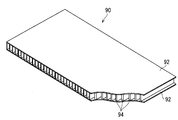
- FIG. 5 is a partially cutaway perspective view showing an example of the hollow plate member 90.
- the hollow plate member 90 includes a plurality of (here, two) plate-like portions 92 and an interposition portion 94 sandwiched between the plurality of plate-like portions 92.
- the material for forming the plurality of plate-like portions 92 and the interposition portions 94 is not particularly limited.
- the plurality of plate-like portions 92 and the interposition portions 94 may be formed of paper, may be formed of resin, or may be configured by a combination thereof.
- the plate-like portion 92 is formed in a flat plate shape. A plurality of plate-like portions 92 are connected via an interposition portion 94 with a space therebetween.
- a plurality of interposition parts 94 are provided in parallel between the plurality of plate-like parts 92 with a space therebetween.
- Each interposition part 94 is formed in an elongated plate shape, and is connected to the plate-like part 92 in a posture orthogonal to the plate-like parts 92 on both sides.
- Such a hollow plate 90 can be continuously manufactured by, for example, an extrusion molding apparatus that extrudes a resin from an extrusion hole corresponding to the ladder-shaped cross section, whereby the plate is easily manufactured at low cost. be able to.
- the hollow plate 90 can also be manufactured by joining two plate-like portions 92 to both sides of a plurality of interposition portions 94 arranged in parallel with each other by heat welding, an adhesive, or the like.
- the plate having a hollow structure is not limited to the above example.
- the plate member may have a configuration in which an intervening portion in which a crest and a trough are continuous in a wave shape is sandwiched between a plurality of plate-like portions.
- the plate material may be one in which intervening portions present between a plurality of plate-like portions form a polygonal columnar hollow shape such as a triangular prism, and in particular, a honeycomb structure. .
- the following advantages can be obtained by forming the interference suppressing member 10 using a hollow plate material. That is, since the plurality of interposition portions 94 are arranged in parallel with the gaps, the hollow plate 90 is difficult to bend along the extending direction of the interposition portions 94, but is easy to bend along the parallel direction of the interposition portions 94. . Further, the strength of the hollow plate 90 is excellent due to the structure forming the hollow structure. Furthermore, since the hollow plate 90 has a hollow structure, it is relatively lightweight for its strength. Further, the material used for the hollow plate 90 is also small for the strength. For this reason, material cost can be held down.
- the sheet-like interference suppression member 14 and the three-dimensional interference suppression member 30 will be described.
- the three-dimensional interference suppression member 30 will be described first.
- the three-dimensional interference suppression member 30 includes a bottom 32 and a side surface 34 as shown in FIG. Furthermore, here, the three-dimensional interference suppression member 30 includes side protrusions 36 and 37.
- the bottom 32 extends along the extending direction of the reinforcement 40 and covers the reinforcement 40 from one direction.
- the bottom portion 32 is formed so as to be dotted with at least one through hole.
- a pair of attachment holes 42 and 43 are provided in the reinforcement 40, a pair of through holes 12 and 13 are formed in the bottom portion 32 with a space therebetween.
- the through holes 12 and 13 are provided at positions corresponding to the attachment holes 42 and 43 provided in the reinforcement 40 in a state where the bottom portion 32 covers the reinforcement 40.
- the through holes 12 and 13 suppress interference when the engagement pieces 73 of the clamps 70 of the wire harness 60 disposed so as to face the reinforcement 40 with the interference suppression member 10 interposed therebetween are fitted into the attachment holes 42 and 43. It is provided so that the member 10 can be inserted.
- the through holes 12 and 13 are formed to be the same as or larger than the attachment holes 42 and 43 (here, slightly larger).
- the through hole 13 formed at a position corresponding to the one attachment hole 43 is also formed in an elliptical shape.
- the side surface portion 34 is a portion that stands on the width direction end of the bottom portion 32 and covers the reinforcement 40 from a direction different from the bottom portion 32. Thereby, the bottom part 32 and the side part 34 surround the periphery of the reinforcement 40. More specifically, here, the side surface portion 34 is erected in a direction perpendicular to the width direction of the bottom portion 32. However, the side surface portion 34 may be erected so as to be continuous with the end portion of the bottom portion 32 in a curved shape.
- the three-dimensional interference suppression member 30 has a hook shape by the side portions 34 being erected on both ends in the width direction of the bottom portion 32. Here, an opening 38 is formed in the side surface portion 34.
- the side surface 34 is separated by the opening 38 into a first side surface 34 a and a second side surface 34 b. From another viewpoint, the first side surface portion 34a and the second side surface portion 34b are provided so as to face each other with the opening 38 interposed therebetween.
- the opening 38 is formed to allow the bracket 50 to extend to the outside.
- a concave portion that is recessed toward the bottom portion 32 from an end portion of the side surface portion 34 opposite to the side connected to the bottom portion 32 is formed.
- the width dimension of the recess is set to be equal to or larger than the width dimension of the bracket 50 (here, slightly larger).
- the side protrusions 36 and 37 are formed so as to extend from the inner peripheral edge of the opening 38.
- the side protrusions 36 and 37 are portions that cover the bracket 50. More specifically, here, the recess is formed until it reaches the bottom 32, and the side protrusions 36, 37 extend from the bottom 32 of the inner peripheral edge of the recess.
- the sheet-like interference suppressing member 14 includes a sheet-like base material 15 as shown in FIG. 16 and slits 18 and 19 are provided.
- a hollow plate material 90 is used as the base material 15.
- the crease 16 is provided at the position of the reference line L extending along the longitudinal direction of the base material 15 at the intermediate portion in the width direction of the base material 15.
- a pair of the reference line L and the fold line 16 are provided.
- the distance between the pair of reference lines L and the crease 16 may be the same as or different from the width dimension of the reinforcement 40.
- the side part 34 is erected so as to be orthogonal to the bottom part 32, so that the distance between the pair of reference lines L and the crease 16 is equal to or larger than the width dimension of the reinforcement 40. (Slightly larger here) is set.
- the fold 16 can be provided along the extending direction of the interposition part 94. Thereby, the base material 15 is easily bent along the crease 16.
- the portion of the base material 15 located between the pair of reference lines L is the bottom equivalent portion 22 that constitutes the bottom 32 of the three-dimensional interference suppression member 30.
- a portion of the base material 15 located on the side of the bottom equivalent portion 22 (a portion located on the opposite side of the bottom equivalent portion 22 across the reference line L) constitutes the side surface portion 34 of the three-dimensional interference suppression member 30.
- side protrusions corresponding to the side protrusions 24 and the side protrusions 36 and 37 of the three-dimensional interference suppression member 30 are examples of the base material 15 located between the pair of reference lines L.
- the slits 18 and 19 are formed in the base material 15 so as to extend from the end in the width direction toward the center in the width direction.
- a pair of slits 18 and 19 are provided in portions of the base material 15 located on both sides of the bottom equivalent portion 22.
- the interval between the pair of slits 18 and 19 is set to be equal to or larger than the width dimension of the bracket 50 (here, slightly larger).
- the slits 18 and 19 are provided until reaching the bottom equivalent portion 22.
- the portions located on the side of the bottom equivalent portion 22 are the side protrusion equivalent portions 26 and 27.
- the part located in the both sides of the side protrusion part equivalent parts 26 and 27 seeing from the width direction of the base material 15 among the parts located in the side of bottom part equivalent part 22 is side part equivalent part 24, One of them is a first side surface portion equivalent 24a, and the other is a second side surface portion equivalent 24b.
- the side protrusion corresponding portions 26 and 27 are left without being bent, and the pair of side surface corresponding portions 24 a and 24 b are bent along the fold line 16, whereby the three-dimensional interference suppression member 30 is changed from the sheet-like interference suppression member 14. Is formed.
- the three-dimensional interference suppression member is formed between the pair of side surface portions 34a and 34b formed by bending the pair of side surface corresponding portions 24a and 24b. Thirty openings 38 are formed.
- the interference suppression member 10 is formed from a sheet-like member.
- the interference suppression member 10 may be formed by resin molding so as to have the same shape as the three-dimensional interference suppression member 30.
- the interference suppression member 10 is formed using a sheet-like member as a material, even if it is bent into a three-dimensional shape later, it can be conveyed in the form of a sheet at the time of conveyance, thereby suppressing the cost of conveyance. Can do.
- adopting a three-dimensional interference suppression member as the interference suppression member 10 compared with the case where it forms by forming a three-dimensional interference suppression member by bending a sheet-like member, it is a metal mold
- the three-dimensional interference suppression member 30 is formed in a bowl shape.
- the three-dimensional interference suppression member 30 may have an L-shaped or V-shaped cross section.
- the sheet-like interference suppression member 14 is provided with only one fold line 16.
- the three-dimensional interference suppression member 30 may be partially formed in a cylindrical shape by connecting the side surface portions 34 at the end opposite to the side connected to the bottom portion 32.
- the side protrusions 36 and 37 may protrude from the bottom part 32, and the side protrusions may protrude from the side part 34.
- the first slit is inserted from the width direction end portion of the base material 15 to the intermediate position of the side surface portion, and the first slit is provided along the longitudinal direction of the base material 15 from the tip of the first slit.
- the portion from the tip of the second slit to the end in the width direction of the base material is a crease, so that the portion of the base material 15 between the second slit and the end in the width direction of the base material 15 is the side It becomes a part corresponding to the protruding part.
- ⁇ Wire harness 60> In the wire harness 60 (see FIG. 7), a plurality of electric wires are bundled in such a manner that at least one branch line portion 64 branches from the main line portion 62. The plurality of electric wires are bundled with a binding member such as a tape or a binding band, for example.
- the wire harness 60 is provided with a clamp 70.
- the electric wire has a configuration in which a covering portion is formed by extrusion coating of resin on the outer periphery of the core wire.
- a connector is provided at an end portion of the electric wire, and is used to electrically connect various electric devices mounted on the vehicle 80 or the like in a state where the connector is disposed at an arrangement target location of the vehicle 80 or the like.
- an optical fiber or the like may be disposed along the electric wire.
- the clamp 70 is a member for fixing the wire harness 60.
- the clamp 70 includes an engaging portion 72 that can be engaged with the mounting holes 42 and 43.
- the clamp 70 is provided in the wire harness 60, and the wire harness 60 is fixed to the reinforcement 40 by engaging the engaging portions 72 of the clamp 70 with the attachment holes 42 and 43 provided in the reinforcement 40.
- the band clamp 70 integrally formed with the band portion 76 is employed as the clamp 70, and also serves as a binding member.
- the band clamp 70 further includes a band portion 76 formed in a band shape and a band locking portion 78 capable of locking the tip of the band portion 76 wound around the electric wire.
- a pair of band clamps 70 are attached to the trunk portion 62.
- the engaging portion 72 can be inserted into the mounting holes 42 and 43 and is formed in a disc spring shape with an engaging piece 73 that can be locked after the insertion, and the engaging piece 73 is formed in the mounting holes 42 and 43.
- a plate portion 74 that holds the edge portions of the mounting holes 42 and 43 in a state of being locked to each other.
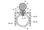
- the band locking portion 78 is formed inside the engagement piece 73 (see FIG. 10).
- a band clamp 70 in which a band locking portion 78 is formed inside the engagement piece 73 is employed as the clamp 70, but other types of clamps 70 may be employed as the clamp 70.
- Other types of clamps 70 include, for example, a band clamp in which a band locking portion is provided under the dish portion, or a fixing plate that is provided under the dish portion, and fixing the fixing plate and the electric wire by tape winding or the like. A type of clamp or the like is conceivable.
- FIG. 6 to FIG. 8 are diagrams showing one step in the method of assembling the wire harness according to the embodiment.
- FIG. 9 is a cross-sectional view taken along line IX-IX in FIG. 10 is a cross-sectional view taken along line XX of FIG.
- FIG. 8 is also a perspective view showing the assembly structure 100 of the wire harness.
- the interference suppression member 10 is attached to at least a part of the elongated reinforcement 40 arranged to extend in the width direction of the vehicle 80 on the back side of the instrument panel 82 of the vehicle 80. Attach (step (a)).
- the three-dimensional interference suppression member 30 is attached to the reinforcement 40. More specifically, the three-dimensional interference suppression member 30 is disposed so that the bottom portion 32 is along the reinforcement 40 and the reinforcement 40 is positioned between the side portions 34 provided at both ends of the bottom portion. Further, the three-dimensional interference suppression member 30 is disposed so that the bracket 50 extends from the opening 38 and the side protrusions 36 and 37 cover the bracket 50.
- the interference suppression member 10 attached at this stage may be a sheet-like interference suppression member 14. Further, the sheet-like base material 15 not provided with the slits 18 and 19 and the crease 16 is attached to the reinforcement 40 as the interference suppression member 10 as it is or a resin molded product having an external shape such as the three-dimensional interference suppression member 30. May be.
- a portion of the bottom portion that covers the reinforcement 40 in a portion where the bracket 50 extends may be formed so as to cover the bracket 50 by protruding sideways. possible.
- step (b) the wire harness 60 is disposed so as to face the reinforcement 40 with the interference suppression member 10 interposed therebetween.
- the trunk portion 62 is disposed so as to face the reinforcement 40 with the bottom portion 32 of the three-dimensional interference suppression member 30 interposed therebetween.
- the branch line portion 64 is disposed so that the base end portion thereof faces the bracket 50 with the side protrusion 37 interposed therebetween.
- the attachment holes 42 and 43 are formed in the reinforcement 40, and the through holes 12 and 13 are formed in the interference suppression member 10 at positions corresponding to the attachment holes 42 and 43.
- the wire harness 60 is provided with a clamp 70 that engages with the mounting holes 42 and 43. Then, the wire harness 60 is fixed to the reinforcement 40 by passing the clamp 70 through the through holes 12 and 13 and then engaging with the attachment holes 42 and 43 (step (b1)).
- the engagement piece 73 of the engagement portion 72 of the clamp 70 is passed through the through hole 12 (13) of the interference suppression member 10, and then the attachment hole 42 (43 of the reinforcement 40 (43). ).
- the plate portion 74 of the clamp 70 is in contact with the interference suppression member 10, but this is not essential.
- the dish part 74 may also pass through the through holes 12 and 13, and the dish part 74 may be in contact with the reinforcement 40.
- the interference suppression member 10 is sandwiched between the electric wire and the reinforcement 40 around the edges of the through holes 12 and 13.
- the interference suppression member 10 is fixed to the reinforcement 40 with a double-sided tape, and the clamp 70 of the wire harness 60 is not provided with the interference suppression member 10.
- the interference suppression member 10 and the wire harness 60 may be separately fixed to the reinforcement 40, for example, when engaged with each other.
- the interference suppression member 10 may be fixed to the reinforcement 40 or may not be fixed.
- a tape which may be a single-sided tape or a double-sided tape
- an adhesive or a protrusion that is inserted into the attachment hole of the reinforcement 40 or the bracket is separately provided on the interference suppressing member. Conceivable.
- the interference suppression member 10 is positioned by arrange
- step (a) the three-dimensional interference suppression member 30 formed by bending the sheet-like interference suppression member 14 is attached to the reinforcement 40. That is, here, the interference suppression member 10 is formed using a sheet-like member whose width dimension is larger than the width dimension of the reinforcement 40. Then, before the step (a), a sheet-like shape is formed so that the interference suppression member 10 and the wire harness 60 are attached to the reinforcement 40 so that a portion of the interference suppression member 10 surrounding the reinforcement 40 is formed. At least a part of the member is bent (step (c)).
- At least one bracket 50 is attached to the reinforcement 40 in such a manner as to extend in a direction crossing the longitudinal direction. Then, at the end in the width direction of the sheet-like member, the width of the bracket 50 is equal to or larger than the width dimension of the bracket 50 so that the opening 38 in which the bracket 50 extends to the outside is formed in the interference suppression member 10. A pair of side surface equivalent portions 24a and 24b facing each other with a gap are bent (step (c1)).
- the side surface portion equivalent portion 24 of the sheet-like interference suppression member 14 is bent along the fold line 16. At this time, the sheet-like interference suppressing member 14 is bent in a bent shape here, but may be bent in a curved shape.
- the pair of side surface equivalent portions 24a and 24b facing each other with the side protrusion corresponding portions 26 and 27 interposed therebetween are bent, leaving the side protrusion corresponding portions 26 and 27.
- the opening 38 from which the bracket 50 extends outside is formed between the pair of side surface portions 34a, 34b formed by bending the pair of side surface portion corresponding portions 24a, 24b.
- step (c) it is not essential that the step (c) is performed before the step (a). Step (c) may be performed between step (a) and step (b), or may be performed after step (b). Moreover, you may be simultaneous with any of process (a) and (b). That is, step (c) may be performed at any stage.
- the sheet-like interference suppression member 14 when the sheet-like interference suppression member 14 is attached to the reinforcement 40 or after the sheet-like interference suppression member 14 is attached, the sheet-like interference suppression member 14 may be bent to form the three-dimensional interference suppression member 30. At this time, the sheet-like interference suppressing member 14 may be bent to form the three-dimensional interference suppressing member 30 before or after the wire harness 60 is disposed on the reinforcement 40. Moreover, it may be simultaneous.
- interference suppression is applied to at least a part of the long reinforcement 40 disposed on the back side of the instrument panel 82 of the vehicle 80 so as to extend in the width direction of the vehicle 80. Since the step (a) of attaching the member 10 is performed before the step (b) of arranging the wire harness 60 so as to face the reinforcement 40 with the interference suppression member 10 interposed therebetween, the periphery of the instrument panel reinforcement 40 The increase in the number of parts constituting the wire harness 60 disposed in the assembly and the complexity of the assembly work can be suppressed.
- a step of bending at least a part of the sheet-like member so that a portion in which the interference suppression member 10 surrounds the reinforcement 40 is formed in a state where the interference suppression member 10 and the wire harness 60 are attached to the reinforcement 40 (c ),
- the interference between the electric wire and the reinforcement 40 in a wider range can be easily suppressed.
- the width of the bracket 50 is equal to or greater than the width dimension of the bracket 50 so that the opening 38 in which the bracket 50 extends to the outside is formed in the interference suppression member 10. Since it further includes the step (c1) of bending the pair of side surface portions 24a and 24b facing each other with a gap, the sheet member can be bent while avoiding the bracket 50. Thereby, interference with the electric wire and reinforcement 40 in a wider range can be suppressed easily.
- the wire harness 60 is further provided with a step (b1) of fixing the wire harness 60 to the reinforcement 40 by passing the clamp 70 through the through holes 12 and 13 and then engaging with the mounting holes 42 and 43.
- the interference suppressing member 10 is also fixed to the reinforcement 40 together. At this time, rattling of the interference suppression member 10 is suppressed by sandwiching the peripheral portions of the through holes 12 and 13 of the interference suppression member 10 between the wire harness 60 and the reinforcement 40.
- the interference suppression member 10 includes the bottom 32 extending along the longitudinal direction of the reinforcement 40, and therefore, before the wire harness 60.
- the three-dimensional interference suppression member 30 further includes the side surface portion 34 in which the width direction end portion of the bottom portion 32 is bent, the three-dimensional interference suppression member 30 can surround the reinforcement 40. Thereby, interference with the wire harness 60 and the reinforcement 40 can be suppressed more reliably.
- the side surface portion 34 avoids the bracket 50 and surrounds the reinforcement 40. be able to.
- the three-dimensional interference suppression member 30 further includes side protrusions 36 and 37 extending in the extending direction of the bracket 50 from the inner peripheral edge of the opening 38 so as to cover the bracket 50, the bracket 50 attaches the wire harness 60. Interference with the electric wire which comprises can be suppressed.
- FIG. 11 is a perspective view showing an interference suppression member 10A according to a modification.
- FIG. 12 is a perspective view illustrating a state in which the wire harness 60 and the interference suppression member 10 ⁇ / b> A according to the modification are attached to the reinforcement 40.
- 11 is a view showing the sheet-like interference suppressing member 14A
- FIG. 12 is also a view showing the assembly structure 100A of the three-dimensional interference suppressing member 30A and the wire harness.
- the same components as those described in the embodiment are denoted by the same reference numerals, and the description thereof is omitted.
- the sheet-like interference suppression member 14 ⁇ / b> A according to the modification is related to the embodiment in that a recess 20 is formed between a pair of side surface equivalent portions 24 a and 24 b located at one end in the width direction of the base material 15. Different from the sheet-like interference suppression member 14. That is, the side protrusion corresponding portion 26 is not provided at one end in the width direction of the base material 15 of the sheet-like interference suppressing member 14A according to the modification. Thereby, in the three-dimensional interference suppression member 30 ⁇ / b> A according to the modification, the side protrusion 36 that protrudes from the inner peripheral edge of the opening 38 is not provided in the one opening 38.
- the interference suppression member 10 ⁇ / b> A includes a bracket 50 attached to the reinforcement 40 and forms an assembly structure 100 ⁇ / b> A of the wire harness. It may be applied when not arranged along the bracket 50.
- the side protrusion corresponding portion 26 in the sheet-like interference suppressing member 14A and the side protrusion 36 in the three-dimensional interference suppressing member 30A are provided.
- the sheet-like interference suppression member 14A and the three-dimensional interference suppression member 30A can be reduced in weight.
Abstract
The purpose of the present invention is to provide a technique whereby it is possible to suppress an increase in the number of components constituting a wire harness arranged on the periphery of an instrument panel reinforcement and an increase in the complexity of assembling the wire harness. The method for assembling a wire harness according to the present invention is provided with (a) a step for attaching an interference suppressing member to at least a portion of a long reinforcement arranged so as to extend in the width direction of a vehicle on the back of the instrument panel of the vehicle, and (b) a step for arranging a wire harness so as to face the reinforcement across the interference suppressing member after the (a) step.
Description
この発明は、インストルメントパネルの裏側に配設されるリインフォースメントにワイヤーハーネスを組み付ける方法に関する。
This invention relates to a method of assembling a wire harness to a reinforcement disposed on the back side of an instrument panel.
自動車等の車両に搭載されるワイヤーハーネスにおいて、電線が、インストルメントパネルの裏側に配設されるリインフォースメント(以降、インパネ用リインフォースメントと称する)に固定されることがある。
In a wire harness mounted on a vehicle such as an automobile, an electric wire may be fixed to a reinforcement (hereinafter referred to as instrument panel reinforcement) disposed on the back side of an instrument panel.
例えば、テープ巻きにより束ねられた複数本の電線が、特許文献1に示されるハーネスクランプによってインパネ用リインフォースメントに固定される。この場合、電線に巻き付けられたテープは、電線がインパネ用リインフォースメント及び周辺部品と接触することを抑制する保護部材として機能する。
For example, a plurality of electric wires bundled by tape winding are fixed to the instrument panel reinforcement by the harness clamp shown in Patent Document 1. In this case, the tape wound around the electric wire functions as a protective member that suppresses the electric wire from coming into contact with the instrument panel reinforcement and the peripheral components.
ところで、電線が固定されたインパネ用リインフォースメントに、この電線の付近に配設された他の電線が接触することがある。この場合、他の電線にも保護部材が必要となる。
By the way, there is a case where another electric wire arranged near the electric wire is in contact with the instrument panel reinforcement to which the electric wire is fixed. In this case, a protective member is also required for the other electric wires.
しかしながら、インパネ用リインフォースメントに配線された複数の電線それぞれに保護部材を取り付ける必要があり、部品点数の増大及び組立て作業の煩雑化が懸念される。
However, it is necessary to attach a protective member to each of the plurality of electric wires wired to the instrument panel reinforcement, which may increase the number of parts and make the assembly work complicated.
本発明は、インパネ用リインフォースメントの周辺に配設されるワイヤーハーネスを構成する部品点数の増大及び組立て作業の煩雑化を抑制できる技術を提供することを目的とする。
This invention aims at providing the technique which can suppress the increase in the number of parts which comprise the wire harness arrange | positioned around the instrument panel reinforcement, and complication of an assembly operation.
上記課題を解決するため、第1の態様に係るワイヤーハーネスの組み付け方法は、(a)車両のインストルメントパネルの裏側に車両の幅方向に延びるように配設される長尺状のリインフォースメントの少なくとも一部に干渉抑制部材を取り付ける工程と、(b)前記工程(a)の後で、前記干渉抑制部材を挟んで前記リインフォースメントに対向するようにワイヤーハーネスを配設する工程と、を備える。
In order to solve the above-described problem, a method of assembling a wire harness according to a first aspect includes: (a) an elongated reinforcement disposed on the back side of an instrument panel of a vehicle so as to extend in the width direction of the vehicle; A step of attaching an interference suppression member to at least a part; and (b) a step of arranging a wire harness so as to face the reinforcement with the interference suppression member interposed therebetween after the step (a). .
第2の態様に係るワイヤーハーネスの組み付け方法は、第1の態様に係るワイヤーハーネスの組み付け方法であって、前記干渉抑制部材が、その幅寸法が前記リインフォースメントの幅寸法よりも大きいシート状部材を材料として形成されており、(c)前記干渉抑制部材が前記リインフォースメントに取り付けられた状態で前記干渉抑制部材が前記リインフォースメントの周囲を囲う部分が形成されるように、前記シート状部材の少なくとも一部を曲げる工程をさらに備える。
The method for assembling the wire harness according to the second aspect is the method for assembling the wire harness according to the first aspect, wherein the interference suppression member is a sheet-like member whose width dimension is larger than the width dimension of the reinforcement. (C) In the state where the interference suppression member is attached to the reinforcement, the portion of the sheet-like member is formed such that a portion of the interference suppression member surrounding the reinforcement is formed. The method further includes a step of bending at least a part.
第3の態様に係るワイヤーハーネスの組み付け方法は、第2の態様に係るワイヤーハーネスの組み付け方法であって、前記リインフォースメントにはその長手方向と交差する方向に延びる態様で少なくとも1つのブラケットが取り付けられ、(c1)前記干渉抑制部材に前記ブラケットが外部に延出する開口が形成されるように、前記シート状部材の幅方向端部において、前記シート状部材の長手方向に沿って前記ブラケットの幅寸法以上の間隔をあけて対向する一対の側面部相当部を曲げる工程をさらに備える。
The method for assembling the wire harness according to the third aspect is the method for assembling the wire harness according to the second aspect, wherein at least one bracket is attached to the reinforcement so as to extend in a direction crossing the longitudinal direction. (C1) at the end in the width direction of the sheet-like member along the longitudinal direction of the sheet-like member so that an opening in which the bracket extends to the outside is formed in the interference suppression member. The method further includes a step of bending a pair of side surface portions corresponding to each other with an interval greater than the width dimension.
第4の態様に係るワイヤーハーネスの組み付け方法は、第1~第3のいずれか1つの態様に係るワイヤーハーネスの組み付け方法であって、前記リインフォースメントには取付孔が形成され、前記干渉抑制部材には前記取付孔に対応する位置に貫通孔が形成され、前記ワイヤーハーネスには前記取付孔に係合するクランプが設けられ、(b1)前記クランプを前記貫通孔に通したうえで前記取付孔に係合させることで、前記ワイヤーハーネスを前記リインフォースメントに固定する工程をさらに備える。
A method of assembling a wire harness according to a fourth aspect is the method of assembling a wire harness according to any one of the first to third aspects, wherein an attachment hole is formed in the reinforcement, and the interference suppressing member A through hole is formed at a position corresponding to the mounting hole, the wire harness is provided with a clamp that engages with the mounting hole, and (b1) the mounting hole is passed through the through hole. It is further provided with the process of fixing the said wire harness to the said reinforcement by engaging with.
第5の態様に係る干渉抑制部材は、シート状部材を材料として形成され、車両のインストルメントパネルの裏側に車両の幅方向に延びるように配設されるリインフォースメントに取り付けられる干渉抑制部材であって、前記リインフォースメントの長手方向に沿って延在する底部を備える。
The interference suppression member according to the fifth aspect is an interference suppression member that is formed from a sheet-like member and is attached to a reinforcement that is disposed on the back side of the vehicle instrument panel so as to extend in the vehicle width direction. And a bottom portion extending along the longitudinal direction of the reinforcement.
第6の態様に係る干渉抑制部材は、第5の態様に係る干渉抑制部材であって、前記底部の幅方向端部が曲げられた側面部をさらに備える。
The interference suppression member according to the sixth aspect is the interference suppression member according to the fifth aspect, and further includes a side surface portion where the widthwise end portion of the bottom portion is bent.
第7の態様に係る干渉抑制部材は、第6の態様に係る干渉抑制部材であって、前記リインフォースメントには、その長手方向と交差する方向に延びる態様で少なくとも1つのブラケットが取り付けられ、前記干渉抑制部材の前記側面部には前記ブラケットが外部に延出可能となるように開口が形成されている。
The interference suppression member according to a seventh aspect is the interference suppression member according to the sixth aspect, wherein the reinforcement is attached with at least one bracket in a mode extending in a direction crossing the longitudinal direction, An opening is formed in the side surface portion of the interference suppressing member so that the bracket can extend to the outside.
第8の態様に係る干渉抑制部材は、第7の態様に係る干渉抑制部材であって、前記干渉抑制部材は、前記ブラケットに被さるように前記開口の内周縁部から前記ブラケットの延出方向に延びる側方突出部をさらに備える。
An interference suppression member according to an eighth aspect is the interference suppression member according to the seventh aspect, wherein the interference suppression member extends from the inner peripheral edge of the opening in the extending direction of the bracket so as to cover the bracket. A lateral protrusion extending further is further provided.
第9の態様に係るワイヤーハーネスの組付構造は、車両のインストルメントパネルの裏側に車両の幅方向に延びるように配設される長尺状のリインフォースメントと、前記リインフォースメントに取り付けられる第5~第8のいずれか1つの態様に係る干渉抑制部材と、前記干渉抑制部材を挟んで前記リインフォースメントに対向するように配設されるワイヤーハーネスと、を備える。
The assembly structure of the wire harness according to the ninth aspect is a long reinforcement disposed on the back side of the instrument panel of the vehicle so as to extend in the width direction of the vehicle, and a fifth attached to the reinforcement. To an interference suppression member according to any one of the eighth aspect, and a wire harness disposed so as to face the reinforcement with the interference suppression member interposed therebetween.
第1~第4の態様に係るワイヤーハーネスの組み付け方法によると、車両のインストルメントパネルの裏側に車両の幅方向に延びるように配設される長尺状のリインフォースメントの少なくとも一部に、干渉抑制部材を取り付ける工程(a)が、干渉抑制部材を挟んでリインフォースメントに対向するようにワイヤーハーネスを配設する工程(b)の前に行われるため、インパネ用リインフォースメントの周辺に配設されるワイヤーハーネスを構成する部品点数の増大及び組立て作業の煩雑化を抑制できる。
According to the method for assembling the wire harness according to the first to fourth aspects, the interference with at least a part of the elongated reinforcement disposed on the back side of the instrument panel of the vehicle so as to extend in the width direction of the vehicle. Since the step (a) for attaching the suppression member is performed before the step (b) for arranging the wire harness so as to face the reinforcement with the interference suppression member interposed therebetween, the step (a) is arranged around the instrument panel reinforcement. The increase in the number of parts constituting the wire harness and the complexity of the assembly work can be suppressed.
特に、第2の態様に係るワイヤーハーネスの組み付け方法によると、干渉抑制部材がその幅寸法がリインフォースメントの幅寸法よりも大きいシート状部材からなり、干渉抑制部材がリインフォースメントに取り付けられた状態で干渉抑制部材がリインフォースメントの周囲を囲う部分が形成されるように、シート状部材の少なくとも一部を曲げる工程(c)をさらに備えるため、より広範囲での電線とリインフォースメントとの干渉を容易に抑制できる。
In particular, according to the assembling method of the wire harness according to the second aspect, the interference suppression member is a sheet-like member whose width dimension is larger than the width dimension of the reinforcement, and the interference suppression member is attached to the reinforcement. Since it further includes a step (c) of bending at least a part of the sheet-like member so that the interference suppression member surrounds the periphery of the reinforcement, the interference between the electric wire and the reinforcement in a wider range is facilitated. Can be suppressed.
特に、第3の態様に係るワイヤーハーネスの組み付け方法によると、干渉抑制部材にブラケットが外部に延出する開口が形成されるように、シート状部材の幅方向端部において、シート状部材の長手方向に沿ってブラケットの幅寸法以上の間隔をあけて対向する一対の側面部相当部を曲げる工程(c1)をさらに備えるため、ブラケットを回避してシート状部材を曲げることができる。これにより、より広範囲での電線とリインフォースメントとの干渉を容易に抑制できる。
In particular, according to the method of assembling the wire harness according to the third aspect, the longitudinal direction of the sheet-like member is formed at the widthwise end of the sheet-like member so that the interference suppressing member has an opening in which the bracket extends to the outside. Since it further includes a step (c1) of bending the pair of side surface portions corresponding to each other with a gap equal to or larger than the width dimension of the bracket along the direction, the sheet-like member can be bent while avoiding the bracket. Thereby, interference with the electric wire and reinforcement in a wider range can be suppressed easily.
特に、第4の態様に係るワイヤーハーネスの組み付け方法によると、クランプを貫通孔に通したうえで取付孔に係合させることで、ワイヤーハーネスをリインフォースメントに固定する工程(b1)をさらに備えるため、干渉抑制部材も合わせてリインフォースメントに固定される。この際、干渉抑制部材のうち貫通孔の周辺部分がワイヤーハーネスとリインフォースメントとによって挟まれることで干渉抑制部材のがたつきが抑えられる。
Particularly, according to the method of assembling the wire harness according to the fourth aspect, the method further includes the step (b1) of fixing the wire harness to the reinforcement by passing the clamp through the through hole and then engaging with the attachment hole. The interference suppression member is also fixed to the reinforcement together. At this time, rattling of the interference suppression member is suppressed by sandwiching the peripheral portion of the through hole in the interference suppression member between the wire harness and the reinforcement.
第5~第8の態様に係る干渉抑制部材によると、リインフォースメントの長手方向に沿って延在する底部を備えるため、ワイヤーハーネスより先に干渉抑制部材をリインフォースメントに取り付けることで、インパネ用リインフォースメントの周辺に配設されるワイヤーハーネスを構成する部品点数の増大及び組立て作業の煩雑化を抑制できる。
According to the interference suppression member according to the fifth to eighth aspects, since the bottom portion extending along the longitudinal direction of the reinforcement is provided, the interference suppression member is attached to the reinforcement before the wire harness. The increase in the number of parts constituting the wire harness arranged around the ment and the complexity of the assembly work can be suppressed.
特に、第6の態様に係る干渉抑制部材によると、干渉抑制部材が側面部を備えるため、干渉抑制部材がリインフォースメントの周囲を囲うことができる。これにより、リインフォースメントとワイヤーハーネスとが干渉することをより確実に抑制することができる。
Particularly, according to the interference suppression member according to the sixth aspect, since the interference suppression member includes the side surface portion, the interference suppression member can surround the periphery of the reinforcement. Thereby, it can suppress more reliably that reinforcement and a wire harness interfere.
特に、第7の態様に係る干渉抑制部材によると、干渉抑制部材の側面部にはブラケットが外部に延出可能となるように開口が形成されているため、側面部がブラケットを回避してリインフォースメントを囲うことができる。
In particular, according to the interference suppression member according to the seventh aspect, since the opening is formed in the side surface portion of the interference suppression member so that the bracket can extend to the outside, the side surface portion avoids the bracket and is reinforced. Can enclose the ment.
特に、第8の態様に係る干渉抑制部材によると、干渉抑制部材は、ブラケットに被さるように開口の内周縁部からブラケットの延出方向に延びる側方突出部をさらに備えるため、ブラケットがワイヤーハーネスを構成する電線と干渉することを抑制することができる。
In particular, according to the interference suppression member according to the eighth aspect, the interference suppression member further includes a side protrusion extending from the inner peripheral edge of the opening in the extending direction of the bracket so as to cover the bracket. It can suppress that it interferes with the electric wire which constitutes.
第9の態様に係るワイヤーハーネスの組付構造によると、車両のインストルメントパネルの裏側に車両の幅方向に延びるように配設される長尺状のリインフォースメントと、リインフォースメントに取り付けられる第5~第8のいずれか1つの態様に係る干渉抑制部材と、干渉抑制部材を挟んでリインフォースメントに対向するように配設されるワイヤーハーネスと、を備えるため、ワイヤーハーネスより先に干渉抑制部材をリインフォースメントに取り付けることで、インパネ用リインフォースメントの周辺に配設されるワイヤーハーネスを構成する部品点数の増大及び組立て作業の煩雑化を抑制できる。
According to the assembling structure of the wire harness according to the ninth aspect, the elongated reinforcement disposed on the back side of the instrument panel of the vehicle so as to extend in the width direction of the vehicle, and the fifth attached to the reinforcement. An interference suppression member according to any one of the eighth aspect and a wire harness disposed so as to face the reinforcement with the interference suppression member interposed therebetween are provided. By attaching to the reinforcement, it is possible to suppress an increase in the number of parts constituting the wire harness disposed around the instrument panel reinforcement and a complicated assembly operation.
{実施形態}
以下、実施形態に係るワイヤーハーネスの組み付け方法について説明する。実施形態に係るワイヤーハーネスの組み付け方法は、車両のインストルメントパネルの裏側に車両の幅方向に延びるように配設されるリインフォースメント(インパネ用リインフォースメント)に、干渉抑制部材を取り付けた後に、ワイヤーハーネスを配設するものである。 {Embodiment}
Hereinafter, a method for assembling the wire harness according to the embodiment will be described. The method of assembling the wire harness according to the embodiment includes attaching an interference suppression member to a reinforcement (instrument reinforcement) arranged to extend in the width direction of the vehicle on the back side of the instrument panel of the vehicle. A harness is disposed.
ここで、実施形態に係るワイヤーハーネスの組み付け方法に用いる各部材について説明する。
Here, each member used for the assembly method of the wire harness according to the embodiment will be described.
<リインフォースメント>
図1は、車両80におけるリインフォースメント40の配設箇所を示す説明図である。図2は、リインフォースメント40を示す斜視図である。 <Reinforcement>
FIG. 1 is an explanatory diagram showing the location of thereinforcement 40 in the vehicle 80. FIG. 2 is a perspective view showing the reinforcement 40.
図1は、車両80におけるリインフォースメント40の配設箇所を示す説明図である。図2は、リインフォースメント40を示す斜視図である。 <Reinforcement>
FIG. 1 is an explanatory diagram showing the location of the
リインフォースメント40は、車両80のインストルメントパネル82の裏側に車両80の幅方向に延びるように配設される。リインフォースメント40は、長尺状(ここでは、長尺な円筒状)に形成されている。ここでは、リインフォースメント40には、取付孔42,43が形成されている。また、ここでは、リインフォースメント40には、ブラケット50が取り付けられている。
The reinforcement 40 is disposed on the back side of the instrument panel 82 of the vehicle 80 so as to extend in the width direction of the vehicle 80. The reinforcement 40 is formed in a long shape (here, a long cylindrical shape). Here, attachment holes 42 and 43 are formed in the reinforcement 40. Here, a bracket 50 is attached to the reinforcement 40.
取付孔42,43は、ワイヤーハーネス60をリインフォースメント40に固定するためのものである。詳しくは後述するが、ここでは、ワイヤーハーネス60にクランプ70が設けられ、当該クランプ70が筒状のリインフォースメント40の外面から内面にかけて貫通する貫通孔状に形成された取付孔42,43に挿入されることでワイヤーハーネス60がリインフォースメント40に固定されている。
The mounting holes 42 and 43 are for fixing the wire harness 60 to the reinforcement 40. Although details will be described later, here, the wire harness 60 is provided with a clamp 70, and the clamp 70 is inserted into mounting holes 42 and 43 formed in a through hole shape penetrating from the outer surface to the inner surface of the cylindrical reinforcement 40. As a result, the wire harness 60 is fixed to the reinforcement 40.
また、ここでは、取付孔42,43は、一対形成されている。一対の取付孔42,43のうちの一方の取付孔43は楕円状に形成され、その長軸方向がリインフォースメント40の延在方向と平行となるように設定されている。これにより、ワイヤーハーネス60に設けられた一対のクランプ70の間隔の寸法公差を吸収することができる。
Further, here, a pair of mounting holes 42 and 43 are formed. One attachment hole 43 of the pair of attachment holes 42, 43 is formed in an elliptical shape, and the major axis direction thereof is set to be parallel to the extending direction of the reinforcement 40. Thereby, the dimensional tolerance of the space | interval of a pair of clamp 70 provided in the wire harness 60 can be absorbed.
ブラケット50は、リインフォースメント40の長手方向に沿って少なくとも1つ取り付けられている。ブラケット50は、例えば、溶接等によりリインフォースメント40に取り付けられる。ここでは、2つのブラケット50が互いに反対方向に延びるようにリインフォースメント40に取り付けられている。
At least one bracket 50 is attached along the longitudinal direction of the reinforcement 40. The bracket 50 is attached to the reinforcement 40 by welding or the like, for example. Here, the two brackets 50 are attached to the reinforcement 40 so as to extend in opposite directions.
ブラケット50にも、貫通孔状の取付孔52が形成されている。ブラケット50の取付孔52は、リインフォースメント40を車体に固定するために用いられる。また、ワイヤーハーネス60をリインフォースメント40に固定するために用いられる場合もあり得る。
The bracket 50 is also formed with a through-hole-shaped mounting hole 52. The mounting hole 52 of the bracket 50 is used for fixing the reinforcement 40 to the vehicle body. Moreover, it may be used for fixing the wire harness 60 to the reinforcement 40.
なお、ここでは、リインフォースメント40は、長尺な円筒状に形成されているものとしたが、リインフォースメント40の形状はこれに限られるものではない。例えば、リインフォースメントは、その断面が角形状に形成されていてもよい。また、例えば、リインフォースメントは、柱状に形成されていてもよい。また、ここでは、リインフォースメント40は、直線状に延びているものとして説明するが、リインフォースメントは、二次元状又は三次元状に延びているものであってもよい。
In addition, although the reinforcement 40 shall be formed in the elongate cylindrical shape here, the shape of the reinforcement 40 is not restricted to this. For example, the reinforcement may have a square cross section. For example, the reinforcement may be formed in a columnar shape. In addition, here, the reinforcement 40 is described as extending linearly, but the reinforcement may extend two-dimensionally or three-dimensionally.
<干渉抑制部材10>
図3は、曲げられる前の干渉抑制部材10を示す斜視図である。図4は、曲げられた後の干渉抑制部材10を示す斜視図である。 <Interference suppression member 10>
FIG. 3 is a perspective view showing theinterference suppressing member 10 before being bent. FIG. 4 is a perspective view showing the interference suppressing member 10 after being bent.
図3は、曲げられる前の干渉抑制部材10を示す斜視図である。図4は、曲げられた後の干渉抑制部材10を示す斜視図である。 <
FIG. 3 is a perspective view showing the
図3に示すように、ここでは、干渉抑制部材10は、シート状の部材を材料として形成されている。干渉抑制部材10は、図3のようにシート状のまま、このまま、若しくは、図4のように曲げられた状態で、リインフォースメント40に取り付けられる。以降、干渉抑制部材10がシート状である場合と、シート状を曲げたものである場合とを区別する必要が有る場合、前者をシート状干渉抑制部材14と称し、後者を立体状干渉抑制部材30と称する。また、両者を区別する必要がない場合は、単に干渉抑制部材10とする。
As shown in FIG. 3, here, the interference suppression member 10 is formed using a sheet-like member as a material. The interference suppression member 10 is attached to the reinforcement 40 in the form of a sheet as shown in FIG. 3, as it is, or as bent as shown in FIG. Henceforth, when it is necessary to distinguish between the case where the interference suppression member 10 is a sheet shape and the case where the interference suppression member 10 is bent, the former is referred to as a sheet-like interference suppression member 14 and the latter is referred to as a three-dimensional interference suppression member. 30. If it is not necessary to distinguish between the two, the interference suppression member 10 is simply used.
干渉抑制部材10を構成する材料は、樹脂等、リインフォースメント40とワイヤーハーネス60を構成する電線との干渉を抑制できるものであれば何であってもよい。好ましくは、リインフォースメント40よりも柔らかいものであって、ブラケット50を溶接することによって生じるバリまたはエッジ等でひび割れ等の傷がつきにくいものであるとよい。より好ましくは、不織布、又は、中空板材90であるとよい。ここでは、干渉抑制部材10は、中空板材90で形成されているものとして説明する。
The material constituting the interference suppressing member 10 may be anything as long as it can suppress interference between the reinforcement 40 and the electric wire constituting the wire harness 60, such as resin. Preferably, it is softer than the reinforcement 40, and is less likely to be damaged such as cracks due to burrs or edges produced by welding the bracket 50. More preferably, it is a nonwoven fabric or a hollow plate 90. Here, the interference suppression member 10 will be described as being formed of the hollow plate 90.
ここで、このような中空板材90の構成について先に説明する。図5は、中空板材90の一例を示す部分切欠き斜視図である。
Here, the configuration of the hollow plate 90 will be described first. FIG. 5 is a partially cutaway perspective view showing an example of the hollow plate member 90.
この中空板材90は、複数(ここでは2つ)の板状部92と、複数の板状部92に挟込まれた介在部94とを備える。
The hollow plate member 90 includes a plurality of (here, two) plate-like portions 92 and an interposition portion 94 sandwiched between the plurality of plate-like portions 92.
複数の板状部92及び介在部94を形成する材質は特に限定されない。複数の板状部92及び介在部94は、紙によって形成されていてもよいし、樹脂によって形成されていてもよいし、また、これらの組み合わせによって構成されていてもよい。複数の板状部92及び介在部94の少なくとも1つを紙によって形成する場合には、その表面に撥水処理等を施すことが好ましい。
The material for forming the plurality of plate-like portions 92 and the interposition portions 94 is not particularly limited. The plurality of plate-like portions 92 and the interposition portions 94 may be formed of paper, may be formed of resin, or may be configured by a combination thereof. When at least one of the plurality of plate-like portions 92 and the interposition portion 94 is formed of paper, it is preferable to perform a water repellent treatment or the like on the surface.
板状部92は、平板状に形成されている。複数の板状部92が介在部94を介して間隔をあけた状態で連結されている。
The plate-like portion 92 is formed in a flat plate shape. A plurality of plate-like portions 92 are connected via an interposition portion 94 with a space therebetween.
ここでは、複数の板状部92の間に、複数の介在部94が相互間に間隔をあけた並列状態で設けられている。
Here, a plurality of interposition parts 94 are provided in parallel between the plurality of plate-like parts 92 with a space therebetween.
各介在部94は、細長い板状に形成されており、両側の板状部92に対して直交する姿勢で、当該板状部92に対して繋がっている。
Each interposition part 94 is formed in an elongated plate shape, and is connected to the plate-like part 92 in a posture orthogonal to the plate-like parts 92 on both sides.
このため、中空板材90を、介在部94の延在方向に対して直交する面で切断すると、一対の板状部92の間に複数の介在部94が並列状に存在するはしご状断面を示す。
For this reason, when the hollow plate member 90 is cut along a plane orthogonal to the extending direction of the interposition part 94, a ladder-like cross section in which a plurality of interposition parts 94 exist in parallel between the pair of plate-like parts 92 is shown. .
このような中空板材90は、例えば、前記はしご状断面に応じた押出孔から樹脂を押出す押出成型装置によって、連続的に製造することができ、これにより、板材を容易に低コストで製造することができる。或は、並列状態に配設される複数の介在部94の両側部に、2つ板状部92を熱溶着、接着剤等で接合することによっても、中空板材90を製造することができる。
Such a hollow plate 90 can be continuously manufactured by, for example, an extrusion molding apparatus that extrudes a resin from an extrusion hole corresponding to the ladder-shaped cross section, whereby the plate is easily manufactured at low cost. be able to. Alternatively, the hollow plate 90 can also be manufactured by joining two plate-like portions 92 to both sides of a plurality of interposition portions 94 arranged in parallel with each other by heat welding, an adhesive, or the like.
中空構造を有する板材の例は上記例に限られない。例えば、板材は、複数の板状部の間に、山部と谷部とが波状に連続する介在部が挟込まれた構成であってもよい。或は、板材は、複数の板状部の間に存在する介在部が三角柱等の多角柱状の中空形状を形成するものであってもよく、特に、ハニカム構造を形成するものであってもよい。
The example of the plate having a hollow structure is not limited to the above example. For example, the plate member may have a configuration in which an intervening portion in which a crest and a trough are continuous in a wave shape is sandwiched between a plurality of plate-like portions. Alternatively, the plate material may be one in which intervening portions present between a plurality of plate-like portions form a polygonal columnar hollow shape such as a triangular prism, and in particular, a honeycomb structure. .
これらの中空構造を有する板材のうち樹脂によって形成されたものは、プラスチックダンボールと呼ばれることもある。
Of these plate materials having a hollow structure, those made of resin are sometimes called plastic corrugated cardboard.
中空板材を材料として干渉抑制部材10を形成することにより、以下の利点を得ることができる。即ち、中空板材90は、複数の介在部94が間隙を設けて並列に配置されているため、介在部94の延在方向に沿って曲がり難い反面、介在部94の並列方向に沿って曲がり易い。また、中空構造を形成する構造体によって、中空板材90の強度は優れたものとなっている。さらに、中空板材90は、中空構造を有するため、強度の割に比較的軽量である。また、中空板材90に使用される材料も、強度の割に少ない。このため、材料費を抑えることができる。
The following advantages can be obtained by forming the interference suppressing member 10 using a hollow plate material. That is, since the plurality of interposition portions 94 are arranged in parallel with the gaps, the hollow plate 90 is difficult to bend along the extending direction of the interposition portions 94, but is easy to bend along the parallel direction of the interposition portions 94. . Further, the strength of the hollow plate 90 is excellent due to the structure forming the hollow structure. Furthermore, since the hollow plate 90 has a hollow structure, it is relatively lightweight for its strength. Further, the material used for the hollow plate 90 is also small for the strength. For this reason, material cost can be held down.
図3及び図4に戻って、シート状干渉抑制部材14及び立体状干渉抑制部材30について説明する。ここでは、説明の便宜上、立体状干渉抑制部材30から先に説明する。
3 and 4, the sheet-like interference suppression member 14 and the three-dimensional interference suppression member 30 will be described. Here, for convenience of explanation, the three-dimensional interference suppression member 30 will be described first.
立体状干渉抑制部材30は、図4に示されるように、底部32と、側面部34とを備える。さらにここでは、立体状干渉抑制部材30は、側方突出部36,37を備える。
The three-dimensional interference suppression member 30 includes a bottom 32 and a side surface 34 as shown in FIG. Furthermore, here, the three-dimensional interference suppression member 30 includes side protrusions 36 and 37.
底部32は、リインフォースメント40の延在方向に沿って延出し、リインフォースメント40に対して1方向から覆う部分である。底部32には、少なくとも1つの貫通孔が点在するように形成されている。ここでは、リインフォースメント40に一対の取付孔42,43が設けられているため、底部32には、一対の貫通孔12,13が間隔をあけて形成されている。
The bottom 32 extends along the extending direction of the reinforcement 40 and covers the reinforcement 40 from one direction. The bottom portion 32 is formed so as to be dotted with at least one through hole. Here, since a pair of attachment holes 42 and 43 are provided in the reinforcement 40, a pair of through holes 12 and 13 are formed in the bottom portion 32 with a space therebetween.
貫通孔12,13は、底部32がリインフォースメント40を覆った状態で、リインフォースメント40に設けられた取付孔42,43に対応する位置に設けられる。貫通孔12,13は、干渉抑制部材10を挟んでリインフォースメント40に対向するように配設されたワイヤーハーネス60のクランプ70の係合片73を取付孔42,43に嵌める際に、干渉抑制部材10を挿通できるように設けられている。具体的には、貫通孔12,13は取付孔42,43と同じかそれよりも大きく(ここでは、若干大きく)形成されている。また、一方の取付孔43が楕円状に形成されているため、一方の取付孔43に対応する位置に形成されている貫通孔13も楕円状に形成されている。
The through holes 12 and 13 are provided at positions corresponding to the attachment holes 42 and 43 provided in the reinforcement 40 in a state where the bottom portion 32 covers the reinforcement 40. The through holes 12 and 13 suppress interference when the engagement pieces 73 of the clamps 70 of the wire harness 60 disposed so as to face the reinforcement 40 with the interference suppression member 10 interposed therebetween are fitted into the attachment holes 42 and 43. It is provided so that the member 10 can be inserted. Specifically, the through holes 12 and 13 are formed to be the same as or larger than the attachment holes 42 and 43 (here, slightly larger). In addition, since one attachment hole 43 is formed in an elliptical shape, the through hole 13 formed at a position corresponding to the one attachment hole 43 is also formed in an elliptical shape.
側面部34は、底部32の幅方向端部に立設され、リインフォースメント40に対して底部32とは異なる方向から覆う部分である。これにより、底部32と側面部34とでリインフォースメント40の周囲を囲っている。より具体的には、ここでは、側面部34は、底部32の幅方向に直交する方向に立設されている。もっとも、側面部34は、底部32の端部と湾曲状に連なるように立設されていてもよい。底部32の幅方向両端にそれぞれ側面部34が立設されることで、立体状干渉抑制部材30は、樋状をなしている。ここでは、側面部34には、開口38が形成されている。当該開口38により側面部34は、第1側面部34aと第2側面部34bとに隔てられている。別の見方をすると、開口38を挟んで対向するように第1側面部34aと第2側面部34bとが設けられている。
The side surface portion 34 is a portion that stands on the width direction end of the bottom portion 32 and covers the reinforcement 40 from a direction different from the bottom portion 32. Thereby, the bottom part 32 and the side part 34 surround the periphery of the reinforcement 40. More specifically, here, the side surface portion 34 is erected in a direction perpendicular to the width direction of the bottom portion 32. However, the side surface portion 34 may be erected so as to be continuous with the end portion of the bottom portion 32 in a curved shape. The three-dimensional interference suppression member 30 has a hook shape by the side portions 34 being erected on both ends in the width direction of the bottom portion 32. Here, an opening 38 is formed in the side surface portion 34. The side surface 34 is separated by the opening 38 into a first side surface 34 a and a second side surface 34 b. From another viewpoint, the first side surface portion 34a and the second side surface portion 34b are provided so as to face each other with the opening 38 interposed therebetween.
開口38は、ブラケット50が外部に延出することを可能にするように形成されている。ここでは、開口38として、側面部34のうち底部32とつながる側とは反対側の端部から、底部32に向かって凹む凹部が形成されている。凹部の幅寸法はブラケット50の幅寸法と同じかそれよりも大きく(ここでは、若干大きく)設定されている。もっとも、開口38として凹部が形成されることは必須ではなく、開口38として側面部34を貫く貫通孔が形成されていてもよい。
The opening 38 is formed to allow the bracket 50 to extend to the outside. Here, as the opening 38, a concave portion that is recessed toward the bottom portion 32 from an end portion of the side surface portion 34 opposite to the side connected to the bottom portion 32 is formed. The width dimension of the recess is set to be equal to or larger than the width dimension of the bracket 50 (here, slightly larger). However, it is not essential that a recess is formed as the opening 38, and a through-hole penetrating the side surface portion 34 may be formed as the opening 38.
側方突出部36,37は、開口38の内周縁部から延びるように形成されている。側方突出部36,37は、ブラケット50を覆う部分である。より具体的には、ここでは、凹部が底部32に達するまで形成されており、側方突出部36,37は、凹部の内周縁部のうち底部32から延出している。
The side protrusions 36 and 37 are formed so as to extend from the inner peripheral edge of the opening 38. The side protrusions 36 and 37 are portions that cover the bracket 50. More specifically, here, the recess is formed until it reaches the bottom 32, and the side protrusions 36, 37 extend from the bottom 32 of the inner peripheral edge of the recess.
次に、シート状干渉抑制部材14について説明する。上記立体状干渉抑制部材30をシート状干渉抑制部材14から得るため、シート状干渉抑制部材14は、図3に示されるように、シート状の基材15を備え、基材15には、折り目16とスリット18,19とが設けられている。ここでは、当該基材15として、中空板材90が用いられている。
Next, the sheet-like interference suppressing member 14 will be described. In order to obtain the three-dimensional interference suppression member 30 from the sheet-like interference suppression member 14, the sheet-like interference suppression member 14 includes a sheet-like base material 15 as shown in FIG. 16 and slits 18 and 19 are provided. Here, a hollow plate material 90 is used as the base material 15.
折り目16は、基材15の幅方向中間部分に基材15の長手方向に沿って延びる基準線Lの位置に設けられている。ここでは、基準線L及び折り目16は、一対設けられている。一対の基準線L及び折り目16の間の間隔は、リインフォースメント40の幅寸法と同じでもよいし、異なっていてもよい。上記立体状干渉抑制部材30において側面部34が底部32に直交するように立設されるため、一対の基準線L及び折り目16の間隔は、リインフォースメント40の幅寸法と同じかそれよりも大きく(ここでは、若干大きく)設定されている。なお、ここでは、シート状干渉抑制部材14を曲げて立体状干渉抑制部材30を形成する際に、後述する側方突出部相当部26,27は曲げないため、側方突出部相当部26,27と底部相当部22との間には折り目16は設けられていない。このため、基材15の長手方向に沿って折り目16が途切れる部分がある。
The crease 16 is provided at the position of the reference line L extending along the longitudinal direction of the base material 15 at the intermediate portion in the width direction of the base material 15. Here, a pair of the reference line L and the fold line 16 are provided. The distance between the pair of reference lines L and the crease 16 may be the same as or different from the width dimension of the reinforcement 40. In the three-dimensional interference suppression member 30, the side part 34 is erected so as to be orthogonal to the bottom part 32, so that the distance between the pair of reference lines L and the crease 16 is equal to or larger than the width dimension of the reinforcement 40. (Slightly larger here) is set. Here, when the sheet-like interference suppression member 14 is bent to form the three-dimensional interference suppression member 30, side projection corresponding portions 26 and 27 described later are not bent, and therefore the side projection corresponding portions 26 and 27 are not bent. The fold 16 is not provided between the portion 27 and the bottom portion 22. For this reason, there is a portion where the crease 16 is interrupted along the longitudinal direction of the substrate 15.
中空板材90の介在部94の延在方向を基材15の長手方向と一致させると、当該折り目16を介在部94の延在方向に沿って設けることができる。これにより、基材15が折り目16に沿って曲がりやすくなる。
When the extending direction of the interposition part 94 of the hollow plate 90 is made to coincide with the longitudinal direction of the base material 15, the fold 16 can be provided along the extending direction of the interposition part 94. Thereby, the base material 15 is easily bent along the crease 16.
ここでは、基材15のうち当該一対の基準線Lの間に位置する部分が、立体状干渉抑制部材30の底部32を構成する底部相当部22である。また、基材15のうち底部相当部22の側方に位置する部分(基準線Lを挟んで底部相当部22の反対側に位置する部分)が立体状干渉抑制部材30の側面部34を構成する側面部相当部24及び立体状干渉抑制部材30の側方突出部36,37を構成する側方突出部相当部26,27である。
Here, the portion of the base material 15 located between the pair of reference lines L is the bottom equivalent portion 22 that constitutes the bottom 32 of the three-dimensional interference suppression member 30. Further, a portion of the base material 15 located on the side of the bottom equivalent portion 22 (a portion located on the opposite side of the bottom equivalent portion 22 across the reference line L) constitutes the side surface portion 34 of the three-dimensional interference suppression member 30. And side protrusions corresponding to the side protrusions 24 and the side protrusions 36 and 37 of the three-dimensional interference suppression member 30.
スリット18,19は、基材15にその幅方向端部から幅方向中心に向かって延びるように形成されている。ここでは、基材15のうち底部相当部22の両側方に位置する部分にそれぞれ一対のスリット18,19が設けられている。一対のスリット18,19の間の間隔は、ブラケット50の幅寸法と同じかそれよりも大きく(ここでは、若干大きく)設定されている。また、ここでは、スリット18,19は、底部相当部22に達するまで設けられている。
The slits 18 and 19 are formed in the base material 15 so as to extend from the end in the width direction toward the center in the width direction. Here, a pair of slits 18 and 19 are provided in portions of the base material 15 located on both sides of the bottom equivalent portion 22. The interval between the pair of slits 18 and 19 is set to be equal to or larger than the width dimension of the bracket 50 (here, slightly larger). Here, the slits 18 and 19 are provided until reaching the bottom equivalent portion 22.
底部相当部22の側方に位置する部分のうち一対のスリット18,19の間に位置する部分が、側方突出部相当部26,27である。そして、底部相当部22の側方に位置する部分のうち基材15の幅方向から見て側方突出部相当部26,27の両側方に位置する部分が、側面部相当部24であり、このうち一方を第1側面部相当分24aとし、他方を第2側面部相当分24bとする。このため、側方突出部相当部26,27を挟んで対向する一対の側面部相当部24a,24bは、ブラケット50の幅寸法以上の間隔をあけて対向しているととらえることができる。
Of the portions located on the side of the bottom equivalent portion 22, the portions located between the pair of slits 18 and 19 are the side protrusion equivalent portions 26 and 27. And the part located in the both sides of the side protrusion part equivalent parts 26 and 27 seeing from the width direction of the base material 15 among the parts located in the side of bottom part equivalent part 22 is side part equivalent part 24, One of them is a first side surface portion equivalent 24a, and the other is a second side surface portion equivalent 24b. For this reason, it can be understood that the pair of side surface portion corresponding portions 24 a and 24 b facing each other with the side protrusion corresponding portions 26 and 27 facing each other with an interval equal to or larger than the width dimension of the bracket 50.
そして、側方突出部相当部26,27は曲げずに残して、一対の側面部相当部24a,24bを折り目16に沿って曲げることで、シート状干渉抑制部材14から立体状干渉抑制部材30が形成される。この際、側方突出部相当部26,27が曲げられないことによって、一対の側面部相当部24a,24bが曲げられてなる一対の側面部34a,34bの間の部分に立体状干渉抑制部材30の開口38が形成される。
Then, the side protrusion corresponding portions 26 and 27 are left without being bent, and the pair of side surface corresponding portions 24 a and 24 b are bent along the fold line 16, whereby the three-dimensional interference suppression member 30 is changed from the sheet-like interference suppression member 14. Is formed. At this time, since the side protrusion corresponding portions 26 and 27 are not bent, the three-dimensional interference suppression member is formed between the pair of side surface portions 34a and 34b formed by bending the pair of side surface corresponding portions 24a and 24b. Thirty openings 38 are formed.
もっとも、干渉抑制部材10がシート状部材を材料として形成されていることは必須ではない。干渉抑制部材10は、例えば、立体状干渉抑制部材30と同様の形状を有するように樹脂成形により形成されていてもよい。しかしながら、干渉抑制部材10がシート状部材を材料として形成されていると、後に立体状に曲げる場合であっても、搬送時には、シート状のままで搬送することで、搬送に係るコストを抑えることができる。また、干渉抑制部材10として、立体状の干渉抑制部材を採用する場合、立体状の干渉抑制部材を、シート状部材を曲げて形成することで、樹脂成形により形成する場合に比べて、金型等の製造コストを抑えることができる。
However, it is not essential that the interference suppression member 10 is formed from a sheet-like member. For example, the interference suppression member 10 may be formed by resin molding so as to have the same shape as the three-dimensional interference suppression member 30. However, when the interference suppression member 10 is formed using a sheet-like member as a material, even if it is bent into a three-dimensional shape later, it can be conveyed in the form of a sheet at the time of conveyance, thereby suppressing the cost of conveyance. Can do. Moreover, when employ | adopting a three-dimensional interference suppression member as the interference suppression member 10, compared with the case where it forms by forming a three-dimensional interference suppression member by bending a sheet-like member, it is a metal mold | die. The manufacturing cost can be reduced.
また、立体状干渉抑制部材30が樋状に形成されることは必須ではない。例えば、立体状干渉抑制部材30はその断面がL字状又はV字状等に形成されていてもよい。この場合、シート状干渉抑制部材14には、折り目16が1本だけ設けられる。また、例えば、立体状干渉抑制部材30は、底部32とつながる側とは反対側の端部で側面部34同士がつながることで、一部で筒状に形成されていることもあり得る。
Further, it is not essential that the three-dimensional interference suppression member 30 is formed in a bowl shape. For example, the three-dimensional interference suppression member 30 may have an L-shaped or V-shaped cross section. In this case, the sheet-like interference suppression member 14 is provided with only one fold line 16. Further, for example, the three-dimensional interference suppression member 30 may be partially formed in a cylindrical shape by connecting the side surface portions 34 at the end opposite to the side connected to the bottom portion 32.
また、側方突出部36,37が底部32から突出することは必須ではなく、側方突出部は、側面部34から突出していてもよい。この場合、シート状干渉抑制部材の段階で基材15の幅方向端部から側面部の中間位置まで第1スリットを入れるとともに、当該第1スリットの先端から基材15の長手方向に沿って第2スリットを入れ、第2スリットの先端から基材の幅方向端部までを折り目とすることで、基材15のうち第2スリットと基材15の幅方向端部との間の部分が側方突出部相当部となる。これにより、シート状干渉抑制部材から側面部から側方突出部が延びている立体状干渉抑制部材を形成することができる。
Further, it is not essential for the side protrusions 36 and 37 to protrude from the bottom part 32, and the side protrusions may protrude from the side part 34. In this case, at the stage of the sheet-like interference suppressing member, the first slit is inserted from the width direction end portion of the base material 15 to the intermediate position of the side surface portion, and the first slit is provided along the longitudinal direction of the base material 15 from the tip of the first slit. 2 slits are inserted, and the portion from the tip of the second slit to the end in the width direction of the base material is a crease, so that the portion of the base material 15 between the second slit and the end in the width direction of the base material 15 is the side It becomes a part corresponding to the protruding part. Thereby, the three-dimensional interference suppression member in which the side protrusion extends from the side surface portion from the sheet-like interference suppression member can be formed.
<ワイヤーハーネス60>
ワイヤーハーネス60(図7参照)は、複数の電線が、幹線部62から少なくとも1つの枝線部64が分岐する態様で束ねられている。複数の電線は、例えば、テープまたは結束バンド等の結束部材で束ねられている。また、ここでは、ワイヤーハーネス60には、クランプ70が設けられている。 <Wire harness 60>
In the wire harness 60 (see FIG. 7), a plurality of electric wires are bundled in such a manner that at least onebranch line portion 64 branches from the main line portion 62. The plurality of electric wires are bundled with a binding member such as a tape or a binding band, for example. Here, the wire harness 60 is provided with a clamp 70.
ワイヤーハーネス60(図7参照)は、複数の電線が、幹線部62から少なくとも1つの枝線部64が分岐する態様で束ねられている。複数の電線は、例えば、テープまたは結束バンド等の結束部材で束ねられている。また、ここでは、ワイヤーハーネス60には、クランプ70が設けられている。 <
In the wire harness 60 (see FIG. 7), a plurality of electric wires are bundled in such a manner that at least one
電線は、芯線の外周に樹脂が押出被覆等されることで被覆部が形成された構成とされている。電線の端部にはコネクタが設けられ、車両80等の配設対象箇所に配設された状態で、車両80等に搭載された各種電気機器同士を電気的に接続するものとして用いられる。なお、ワイヤーハーネス60には、光ファイバ等が電線に沿って配設されていてもよい。
The electric wire has a configuration in which a covering portion is formed by extrusion coating of resin on the outer periphery of the core wire. A connector is provided at an end portion of the electric wire, and is used to electrically connect various electric devices mounted on the vehicle 80 or the like in a state where the connector is disposed at an arrangement target location of the vehicle 80 or the like. In the wire harness 60, an optical fiber or the like may be disposed along the electric wire.
クランプ70は、ワイヤーハーネス60を固定するための部材である。クランプ70は、取付孔42,43に係合可能な係合部72を含む。ワイヤーハーネス60にクランプ70が設けられ、クランプ70の係合部72がリインフォースメント40に設けられた取付孔42,43に係合することで、ワイヤーハーネス60がリインフォースメント40に固定される。ここでは、クランプ70として、バンド部76と一体成形されたバンドクランプ70が採用され、結束部材としての役割も兼ねている。
The clamp 70 is a member for fixing the wire harness 60. The clamp 70 includes an engaging portion 72 that can be engaged with the mounting holes 42 and 43. The clamp 70 is provided in the wire harness 60, and the wire harness 60 is fixed to the reinforcement 40 by engaging the engaging portions 72 of the clamp 70 with the attachment holes 42 and 43 provided in the reinforcement 40. Here, the band clamp 70 integrally formed with the band portion 76 is employed as the clamp 70, and also serves as a binding member.
バンドクランプ70は、係合部72に加えて、帯状に形成されたバンド部76と、電線の周囲に巻回されたバンド部76の先端を係止可能なバンド係止部78とをさらに含む。ここでは、バンドクランプ70は、幹線部62に一対取り付けられている。また、ここでは、係合部72は、取付孔42,43に挿通可能で、挿通後に係止可能な係合片73と、皿バネ状に形成され、係合片73が取付孔42,43に係止した状態で取付孔42,43の縁部を押さえる皿部74とを含む。また、ここでは、バンド係止部78は係合片73の内部に形成されている(図10参照)。
In addition to the engaging portion 72, the band clamp 70 further includes a band portion 76 formed in a band shape and a band locking portion 78 capable of locking the tip of the band portion 76 wound around the electric wire. . Here, a pair of band clamps 70 are attached to the trunk portion 62. In addition, here, the engaging portion 72 can be inserted into the mounting holes 42 and 43 and is formed in a disc spring shape with an engaging piece 73 that can be locked after the insertion, and the engaging piece 73 is formed in the mounting holes 42 and 43. And a plate portion 74 that holds the edge portions of the mounting holes 42 and 43 in a state of being locked to each other. Here, the band locking portion 78 is formed inside the engagement piece 73 (see FIG. 10).
なお、ここでは、クランプ70として、係合片73の内部にバンド係止部78が形成されたバンドクランプ70が採用されているが、クランプ70として他の種類のクランプ70が採用されていてもよい。他の種類のクランプ70としては、例えば、バンド係止部が皿部の下に設けられたバンドクランプ、又は皿部の下に固定板が設けられ、固定板と電線とをテープ巻等で固定するタイプのクランプ等が考えられる。
Here, a band clamp 70 in which a band locking portion 78 is formed inside the engagement piece 73 is employed as the clamp 70, but other types of clamps 70 may be employed as the clamp 70. Good. Other types of clamps 70 include, for example, a band clamp in which a band locking portion is provided under the dish portion, or a fixing plate that is provided under the dish portion, and fixing the fixing plate and the electric wire by tape winding or the like. A type of clamp or the like is conceivable.
<組み付け方法>
次に、ワイヤーハーネスの組み付け方法について説明する。図6~図8は、それぞれ、実施形態に係るワイヤーハーネスの組み付け方法の一工程を示す図である。図9は、図8のIX-IX線に沿って切断した断面図である。図10は、図8のX-X線に沿って切断した断面図である。なお、図8は、ワイヤーハーネスの組付構造100を示す斜視図でもある。 <Assembly method>
Next, a method for assembling the wire harness will be described. FIG. 6 to FIG. 8 are diagrams showing one step in the method of assembling the wire harness according to the embodiment. FIG. 9 is a cross-sectional view taken along line IX-IX in FIG. 10 is a cross-sectional view taken along line XX of FIG. FIG. 8 is also a perspective view showing theassembly structure 100 of the wire harness.
次に、ワイヤーハーネスの組み付け方法について説明する。図6~図8は、それぞれ、実施形態に係るワイヤーハーネスの組み付け方法の一工程を示す図である。図9は、図8のIX-IX線に沿って切断した断面図である。図10は、図8のX-X線に沿って切断した断面図である。なお、図8は、ワイヤーハーネスの組付構造100を示す斜視図でもある。 <Assembly method>
Next, a method for assembling the wire harness will be described. FIG. 6 to FIG. 8 are diagrams showing one step in the method of assembling the wire harness according to the embodiment. FIG. 9 is a cross-sectional view taken along line IX-IX in FIG. 10 is a cross-sectional view taken along line XX of FIG. FIG. 8 is also a perspective view showing the
まずは、図6にあるように、車両80のインストルメントパネル82の裏側に車両80の幅方向に延びるように配設される長尺状のリインフォースメント40の少なくとも一部に、干渉抑制部材10を取り付ける(工程(a))。
First, as shown in FIG. 6, the interference suppression member 10 is attached to at least a part of the elongated reinforcement 40 arranged to extend in the width direction of the vehicle 80 on the back side of the instrument panel 82 of the vehicle 80. Attach (step (a)).
具体的には、ここでは、立体状干渉抑制部材30をリインフォースメント40に取り付けている。より詳細には、底部32がリインフォースメント40に沿うとともに、底部の両端にそれぞれ設けられた側面部34の間にリインフォースメント40が位置するように立体状干渉抑制部材30を配設する。また、開口38からブラケット50が延出し、側方突出部36,37がブラケット50を覆うように立体状干渉抑制部材30を配設する。
Specifically, here, the three-dimensional interference suppression member 30 is attached to the reinforcement 40. More specifically, the three-dimensional interference suppression member 30 is disposed so that the bottom portion 32 is along the reinforcement 40 and the reinforcement 40 is positioned between the side portions 34 provided at both ends of the bottom portion. Further, the three-dimensional interference suppression member 30 is disposed so that the bracket 50 extends from the opening 38 and the side protrusions 36 and 37 cover the bracket 50.
もっとも、この段階で取り付ける干渉抑制部材10としては、シート状干渉抑制部材14であってもよい。また、スリット18,19及び折り目16の設けられていないシート状の基材15そのまま、或いは、立体状干渉抑制部材30のような外形を有する樹脂成形品を干渉抑制部材10としてリインフォースメント40に取り付けてもよい。
However, the interference suppression member 10 attached at this stage may be a sheet-like interference suppression member 14. Further, the sheet-like base material 15 not provided with the slits 18 and 19 and the crease 16 is attached to the reinforcement 40 as the interference suppression member 10 as it is or a resin molded product having an external shape such as the three-dimensional interference suppression member 30. May be.
干渉抑制部材がシート状の基材15そのままの場合、底部のうちブラケット50が伸びる部分のリインフォースメント40を覆っている部分が側方に張出して、ブラケット50を覆うように形成されていることもあり得る。
When the interference suppression member is the sheet-like base material 15 as it is, a portion of the bottom portion that covers the reinforcement 40 in a portion where the bracket 50 extends may be formed so as to cover the bracket 50 by protruding sideways. possible.
次に、図7にあるように、工程(a)の後で、干渉抑制部材10を挟んでリインフォースメント40に対向するようにワイヤーハーネス60を配設する(工程(b))。
Next, as shown in FIG. 7, after the step (a), the wire harness 60 is disposed so as to face the reinforcement 40 with the interference suppression member 10 interposed therebetween (step (b)).
具体的には、ここでは、幹線部62を立体状干渉抑制部材30の底部32を挟んでリインフォースメント40と対向するように配設する。また、枝線部64をその基端部が側方突出部37を挟んでブラケット50と対向するように配設している。
Specifically, here, the trunk portion 62 is disposed so as to face the reinforcement 40 with the bottom portion 32 of the three-dimensional interference suppression member 30 interposed therebetween. Further, the branch line portion 64 is disposed so that the base end portion thereof faces the bracket 50 with the side protrusion 37 interposed therebetween.
この際、ここでは、リインフォースメント40には取付孔42,43が形成されるとともに、干渉抑制部材10には取付孔42,43に対応する位置に貫通孔12,13が形成されている。また、ワイヤーハーネス60には取付孔42,43に係合するクランプ70が設けられている。そして、クランプ70を貫通孔12,13に通したうえで取付孔42,43に係合させることで、ワイヤーハーネス60をリインフォースメント40に固定する(工程(b1))。
At this time, here, the attachment holes 42 and 43 are formed in the reinforcement 40, and the through holes 12 and 13 are formed in the interference suppression member 10 at positions corresponding to the attachment holes 42 and 43. The wire harness 60 is provided with a clamp 70 that engages with the mounting holes 42 and 43. Then, the wire harness 60 is fixed to the reinforcement 40 by passing the clamp 70 through the through holes 12 and 13 and then engaging with the attachment holes 42 and 43 (step (b1)).
具体的には、図10のように、クランプ70の係合部72の係合片73を干渉抑制部材10の貫通孔12(13)に通したうえで、リインフォースメント40の取付孔42(43)に係合させている。この際に、図10では、クランプ70の皿部74が干渉抑制部材10と接しているが、このことは必須ではない。皿部74も貫通孔12,13を通過し、皿部74がリインフォースメント40と接していてもよい。この場合、干渉抑制部材10は、貫通孔12,13の縁部周辺で電線とリインフォースメント40とに挟み込まれる。
Specifically, as shown in FIG. 10, the engagement piece 73 of the engagement portion 72 of the clamp 70 is passed through the through hole 12 (13) of the interference suppression member 10, and then the attachment hole 42 (43 of the reinforcement 40 (43). ). At this time, in FIG. 10, the plate portion 74 of the clamp 70 is in contact with the interference suppression member 10, but this is not essential. The dish part 74 may also pass through the through holes 12 and 13, and the dish part 74 may be in contact with the reinforcement 40. In this case, the interference suppression member 10 is sandwiched between the electric wire and the reinforcement 40 around the edges of the through holes 12 and 13.
もっとも、工程(b1)が行われることは必須ではなく、例えば、干渉抑制部材10が両面テープによりリインフォースメント40に固定されるとともに、ワイヤーハーネス60のクランプ70が干渉抑制部材10のないところで取付孔に係合している場合など、干渉抑制部材10とワイヤーハーネス60とがそれぞれ別々にリインフォースメント40に固定されていることもあり得る。
However, it is not essential that the step (b1) is performed. For example, the interference suppression member 10 is fixed to the reinforcement 40 with a double-sided tape, and the clamp 70 of the wire harness 60 is not provided with the interference suppression member 10. The interference suppression member 10 and the wire harness 60 may be separately fixed to the reinforcement 40, for example, when engaged with each other.
以上のように、リインフォースメント40に干渉抑制部材10及びワイヤーハーネス60を取り付けることで、図8に示されるワイヤーハーネスの組付構造100が完成となる。
As described above, by attaching the interference suppression member 10 and the wire harness 60 to the reinforcement 40, the assembly structure 100 of the wire harness shown in FIG. 8 is completed.
なお、リインフォースメント40に干渉抑制部材10を取り付ける工程(a)においては、リインフォースメント40に干渉抑制部材10を固定してもよいし、固定しなくてもよい。固定する場合としては、例えば、テープ(片面テープでもよいし、両面テープでもよい)、接着剤、又は、干渉抑制部材にリインフォースメント40またはブラケットの取付孔に挿通される突部を別途設けるなどが考えられる。また、固定しない場合は、工程(b)でワイヤーハーネス60を配設することで、干渉抑制部材10が位置決めされることが好ましい。この場合、干渉抑制部材10は、ワイヤーハーネス60を配設することで位置決めされるまで、例えば、自重により静止している、又は、作業者の手で押さえられていることが考えられる。
In addition, in the process (a) of attaching the interference suppression member 10 to the reinforcement 40, the interference suppression member 10 may be fixed to the reinforcement 40 or may not be fixed. As a case of fixing, for example, a tape (which may be a single-sided tape or a double-sided tape), an adhesive, or a protrusion that is inserted into the attachment hole of the reinforcement 40 or the bracket is separately provided on the interference suppressing member. Conceivable. Moreover, when not fixing, it is preferable that the interference suppression member 10 is positioned by arrange | positioning the wire harness 60 at a process (b). In this case, until the interference suppression member 10 is positioned by disposing the wire harness 60, for example, it is conceivable that the interference suppression member 10 is stationary due to its own weight or is held by the operator's hand.
上述したように、ここでは、工程(a)において、リインフォースメント40にシート状干渉抑制部材14を曲げてなる立体状干渉抑制部材30を取り付けている。即ち、ここでは、干渉抑制部材10が、その幅寸法がリインフォースメント40の幅寸法よりも大きいシート状部材を材料として形成されている。そして、干渉抑制部材10及びワイヤーハーネス60がリインフォースメント40に取り付けられた状態で干渉抑制部材10がリインフォースメント40の周囲を囲う部分が形成されるように、工程(a)の前に、シート状部材の少なくとも一部を曲げている(工程(c))。
As described above, here, in step (a), the three-dimensional interference suppression member 30 formed by bending the sheet-like interference suppression member 14 is attached to the reinforcement 40. That is, here, the interference suppression member 10 is formed using a sheet-like member whose width dimension is larger than the width dimension of the reinforcement 40. Then, before the step (a), a sheet-like shape is formed so that the interference suppression member 10 and the wire harness 60 are attached to the reinforcement 40 so that a portion of the interference suppression member 10 surrounding the reinforcement 40 is formed. At least a part of the member is bent (step (c)).
さらに、ここでは、リインフォースメント40にはその長手方向と交差する方向に延びる態様で少なくとも1つのブラケット50が取り付けられている。そして、干渉抑制部材10にブラケット50が外部に延出する開口38が形成されるように、シート状部材の幅方向端部において、シート状部材の長手方向に沿ってブラケット50の幅寸法以上の間隔をあけて対向する一対の側面部相当部24a,24bを曲げる(工程(c1))。
Further, here, at least one bracket 50 is attached to the reinforcement 40 in such a manner as to extend in a direction crossing the longitudinal direction. Then, at the end in the width direction of the sheet-like member, the width of the bracket 50 is equal to or larger than the width dimension of the bracket 50 so that the opening 38 in which the bracket 50 extends to the outside is formed in the interference suppression member 10. A pair of side surface equivalent portions 24a and 24b facing each other with a gap are bent (step (c1)).
具体的には、折り目16に沿ってシート状干渉抑制部材14の側面部相当部24を曲げる。この際、ここでは、シート状干渉抑制部材14を屈曲状に曲げているが、湾曲状に曲げてもよい。また、ここでは、側方突出部相当部26,27を残して、側方突出部相当部26,27を挟んで対向する一対の側面部相当部24a,24bを曲げる。これにより、一対の側面部相当部24a,24bが曲げられてなる一対の側面部34a,34bの間にブラケット50が外部に延出する開口38が形成される。
Specifically, the side surface portion equivalent portion 24 of the sheet-like interference suppression member 14 is bent along the fold line 16. At this time, the sheet-like interference suppressing member 14 is bent in a bent shape here, but may be bent in a curved shape. In addition, here, the pair of side surface equivalent portions 24a and 24b facing each other with the side protrusion corresponding portions 26 and 27 interposed therebetween are bent, leaving the side protrusion corresponding portions 26 and 27. Thereby, the opening 38 from which the bracket 50 extends outside is formed between the pair of side surface portions 34a, 34b formed by bending the pair of side surface portion corresponding portions 24a, 24b.
なお、工程(c)が工程(a)の前に行われることは必須ではない。工程(c)は、工程(a)と工程(b)との間に行われてもよいし、工程(b)の後に行われてもよい。また、工程(a)、(b)のいずれかと同時であっても構わない。つまり、工程(c)はどの段階で行われても構わない。
In addition, it is not essential that the step (c) is performed before the step (a). Step (c) may be performed between step (a) and step (b), or may be performed after step (b). Moreover, you may be simultaneous with any of process (a) and (b). That is, step (c) may be performed at any stage.
具体的には、シート状干渉抑制部材14のままリインフォースメント40に取り付ける際または取り付けた後に、シート状干渉抑制部材14を曲げて立体状干渉抑制部材30としてもよい。この際、シート状干渉抑制部材14を曲げて立体状干渉抑制部材30となすのは、ワイヤーハーネス60がリインフォースメント40に配設される前であってもよいし、後であってもよい。また、同時であってもよい。
Specifically, when the sheet-like interference suppression member 14 is attached to the reinforcement 40 or after the sheet-like interference suppression member 14 is attached, the sheet-like interference suppression member 14 may be bent to form the three-dimensional interference suppression member 30. At this time, the sheet-like interference suppressing member 14 may be bent to form the three-dimensional interference suppressing member 30 before or after the wire harness 60 is disposed on the reinforcement 40. Moreover, it may be simultaneous.
実施形態に係るワイヤーハーネスの組み付け方法によると、車両80のインストルメントパネル82の裏側に車両80の幅方向に延びるように配設される長尺状のリインフォースメント40の少なくとも一部に、干渉抑制部材10を取り付ける工程(a)が、干渉抑制部材10を挟んでリインフォースメント40に対向するようにワイヤーハーネス60を配設する工程(b)の前に行われるため、インパネ用リインフォースメント40の周辺に配設されるワイヤーハーネス60を構成する部品点数の増大及び組立て作業の煩雑化を抑制できる。
According to the method for assembling the wire harness according to the embodiment, interference suppression is applied to at least a part of the long reinforcement 40 disposed on the back side of the instrument panel 82 of the vehicle 80 so as to extend in the width direction of the vehicle 80. Since the step (a) of attaching the member 10 is performed before the step (b) of arranging the wire harness 60 so as to face the reinforcement 40 with the interference suppression member 10 interposed therebetween, the periphery of the instrument panel reinforcement 40 The increase in the number of parts constituting the wire harness 60 disposed in the assembly and the complexity of the assembly work can be suppressed.
また、干渉抑制部材10及びワイヤーハーネス60がリインフォースメント40に取り付けられた状態で干渉抑制部材10がリインフォースメント40を囲う部分が形成されるように、シート状部材の少なくとも一部を曲げる工程(c)をさらに備えるため、より広範囲での電線とリインフォースメント40との干渉を容易に抑制できる。
In addition, a step of bending at least a part of the sheet-like member so that a portion in which the interference suppression member 10 surrounds the reinforcement 40 is formed in a state where the interference suppression member 10 and the wire harness 60 are attached to the reinforcement 40 (c ), The interference between the electric wire and the reinforcement 40 in a wider range can be easily suppressed.
また、干渉抑制部材10にブラケット50が外部に延出する開口38が形成されるように、シート状部材の幅方向端部において、シート状部材の長手方向に沿ってブラケット50の幅寸法以上の間隔をあけて対向する一対の側面部相当部24a,24bを曲げる工程(c1)をさらに備えるため、ブラケット50を回避してシート状部材を曲げることができる。これにより、より広範囲での電線とリインフォースメント40との干渉を容易に抑制できる。
In addition, at the end in the width direction of the sheet-like member, the width of the bracket 50 is equal to or greater than the width dimension of the bracket 50 so that the opening 38 in which the bracket 50 extends to the outside is formed in the interference suppression member 10. Since it further includes the step (c1) of bending the pair of side surface portions 24a and 24b facing each other with a gap, the sheet member can be bent while avoiding the bracket 50. Thereby, interference with the electric wire and reinforcement 40 in a wider range can be suppressed easily.
また、クランプ70を貫通孔12,13に通したうえで取付孔42,43に係合させることで、ワイヤーハーネス60をリインフォースメント40に固定する工程(b1)をさらに備えるため、ワイヤーハーネス60をリインフォースメント40に固定する際に干渉抑制部材10も合わせてリインフォースメント40に固定される。また、この際、干渉抑制部材10のうち貫通孔12,13の周辺部分がワイヤーハーネス60とリインフォースメント40とによって挟まれることで干渉抑制部材10のがたつきが抑えられる。
Further, the wire harness 60 is further provided with a step (b1) of fixing the wire harness 60 to the reinforcement 40 by passing the clamp 70 through the through holes 12 and 13 and then engaging with the mounting holes 42 and 43. When fixing to the reinforcement 40, the interference suppressing member 10 is also fixed to the reinforcement 40 together. At this time, rattling of the interference suppression member 10 is suppressed by sandwiching the peripheral portions of the through holes 12 and 13 of the interference suppression member 10 between the wire harness 60 and the reinforcement 40.
また、実施形態に係る干渉抑制部材10及びワイヤーハーネスの組付構造100によると、干渉抑制部材10がリインフォースメント40の長手方向に沿って延在する底部32を備えるため、ワイヤーハーネス60より先に干渉抑制部材10をリインフォースメント40に取り付けることで、インパネ用リインフォースメント40の周辺に配設されるワイヤーハーネス60を構成する部品点数の増大及び組立て作業の煩雑化を抑制できる。
In addition, according to the assembly structure 100 of the interference suppression member 10 and the wire harness according to the embodiment, the interference suppression member 10 includes the bottom 32 extending along the longitudinal direction of the reinforcement 40, and therefore, before the wire harness 60. By attaching the interference suppression member 10 to the reinforcement 40, it is possible to suppress an increase in the number of parts constituting the wire harness 60 disposed around the instrument panel reinforcement 40 and complication of the assembly work.
また、立体状干渉抑制部材30が、底部32の幅方向端部が曲げられた側面部34をさらに備えるため、立体状干渉抑制部材30がリインフォースメント40の周囲を囲うことができる。これにより、ワイヤーハーネス60とリインフォースメント40との干渉をより確実に抑制することができる。
Moreover, since the three-dimensional interference suppression member 30 further includes the side surface portion 34 in which the width direction end portion of the bottom portion 32 is bent, the three-dimensional interference suppression member 30 can surround the reinforcement 40. Thereby, interference with the wire harness 60 and the reinforcement 40 can be suppressed more reliably.
また、立体状干渉抑制部材30の側面部34にはブラケット50が外部に延出可能となるように開口38が形成されているため、側面部34がブラケット50を回避してリインフォースメント40を囲うことができる。
Moreover, since the opening 38 is formed in the side surface portion 34 of the three-dimensional interference suppression member 30 so that the bracket 50 can extend to the outside, the side surface portion 34 avoids the bracket 50 and surrounds the reinforcement 40. be able to.
また、立体状干渉抑制部材30は、ブラケット50に被さるように開口38の内周縁部からブラケット50の延出方向に延びる側方突出部36,37をさらに備えるため、ブラケット50がワイヤーハーネス60を構成する電線と干渉することを抑制することができる。
Further, since the three-dimensional interference suppression member 30 further includes side protrusions 36 and 37 extending in the extending direction of the bracket 50 from the inner peripheral edge of the opening 38 so as to cover the bracket 50, the bracket 50 attaches the wire harness 60. Interference with the electric wire which comprises can be suppressed.
{変形例}
図11は、変形例に係る干渉抑制部材10Aを示す斜視図である。図12は、ワイヤーハーネス60及び変形例に係る干渉抑制部材10Aがリインフォースメント40に取り付けられた様子を示す斜視図である。なお、図11は、シート状干渉抑制部材14Aを示す図であり、図12は、立体状干渉抑制部材30A及びワイヤーハーネスの組付構造100Aを示す図でもある。また、本変形例の説明において、実施形態で説明したものと同様構成要素については同一符号を付してその説明を省略する。 {Modifications}
FIG. 11 is a perspective view showing aninterference suppression member 10A according to a modification. FIG. 12 is a perspective view illustrating a state in which the wire harness 60 and the interference suppression member 10 </ b> A according to the modification are attached to the reinforcement 40. 11 is a view showing the sheet-like interference suppressing member 14A, and FIG. 12 is also a view showing the assembly structure 100A of the three-dimensional interference suppressing member 30A and the wire harness. In the description of this modification, the same components as those described in the embodiment are denoted by the same reference numerals, and the description thereof is omitted.
図11は、変形例に係る干渉抑制部材10Aを示す斜視図である。図12は、ワイヤーハーネス60及び変形例に係る干渉抑制部材10Aがリインフォースメント40に取り付けられた様子を示す斜視図である。なお、図11は、シート状干渉抑制部材14Aを示す図であり、図12は、立体状干渉抑制部材30A及びワイヤーハーネスの組付構造100Aを示す図でもある。また、本変形例の説明において、実施形態で説明したものと同様構成要素については同一符号を付してその説明を省略する。 {Modifications}
FIG. 11 is a perspective view showing an
変形例に係るシート状干渉抑制部材14Aは、基材15の幅方向一方側端部に位置する一対の側面部相当部24a,24bの間に凹部20が形成されている点で実施形態に係るシート状干渉抑制部材14とは異なる。つまり、変形例に係るシート状干渉抑制部材14Aの基材15の幅方向一方側端部には、側方突出部相当部26が設けられていない。これにより、変形例に係る立体状干渉抑制部材30Aでは、一方の開口38において開口38の内周縁部から突出する側方突出部36が設けられていない。
The sheet-like interference suppression member 14 </ b> A according to the modification is related to the embodiment in that a recess 20 is formed between a pair of side surface equivalent portions 24 a and 24 b located at one end in the width direction of the base material 15. Different from the sheet-like interference suppression member 14. That is, the side protrusion corresponding portion 26 is not provided at one end in the width direction of the base material 15 of the sheet-like interference suppressing member 14A according to the modification. Thereby, in the three-dimensional interference suppression member 30 </ b> A according to the modification, the side protrusion 36 that protrudes from the inner peripheral edge of the opening 38 is not provided in the one opening 38.
このような干渉抑制部材10Aは、例えば図12のように、リインフォースメント40にブラケット50が取り付けられ、ワイヤーハーネスの組付構造100Aをなすが、ワイヤーハーネス60の幹線部62及び枝線部64が当該ブラケット50に沿って配設されない場合などに適用されるとよい。
For example, as shown in FIG. 12, the interference suppression member 10 </ b> A includes a bracket 50 attached to the reinforcement 40 and forms an assembly structure 100 </ b> A of the wire harness. It may be applied when not arranged along the bracket 50.
変形例に係る干渉抑制部材10A及びワイヤーハーネスの組付構造100Aによると、シート状干渉抑制部材14Aにおける側方突出部相当部26及び立体状干渉抑制部材30Aにおける側方突出部36が設けられていないことで、シート状干渉抑制部材14A及び立体状干渉抑制部材30Aを軽量化できる。
According to the interference suppressing member 10A and the wire harness assembly structure 100A according to the modified example, the side protrusion corresponding portion 26 in the sheet-like interference suppressing member 14A and the side protrusion 36 in the three-dimensional interference suppressing member 30A are provided. By being absent, the sheet-like interference suppression member 14A and the three-dimensional interference suppression member 30A can be reduced in weight.
なお、上記実施形態及び変形例で説明した各構成は、相互に矛盾しない限り適宜組み合わせることができる。
In addition, each structure demonstrated by the said embodiment and modification can be suitably combined unless it mutually contradicts.
以上のようにこの発明は詳細に説明されたが、上記した説明は、すべての局面において、例示であって、この発明がそれに限定されるものではない。例示されていない無数の変形例が、この発明の範囲から外れることなく想定され得るものと解される。
Although the present invention has been described in detail as described above, the above description is illustrative in all aspects, and the present invention is not limited thereto. It is understood that countless variations that are not illustrated can be envisaged without departing from the scope of the present invention.
10,10A 干渉抑制部材
12,13 貫通孔
14,14A シート状干渉抑制部材
15 基材
16 折り目
18,19 スリット
20 凹部
22 底部相当部
24 側面部相当部
26,27 側方突出部相当部
30,30A 立体状干渉抑制部材
32 底部
34 側面部
36,37 側方突出部
38 開口
40 リインフォースメント
42,43 取付孔
50 ブラケット
52 取付孔
60 ワイヤーハーネス
70 バンドクランプ
72 係合部
80 車両
82 インストルメントパネル
90 中空板材
100,100A ワイヤーハーネスの組付構造
L 基準線 DESCRIPTION OF SYMBOLS 10,10A Interference suppression member 12,13 Through- hole 14,14A Sheet-like interference suppression member 15 Base material 16 Fold line 18,19 Slit 20 Recessed part 22 Bottom part equivalent part 24 Side part equivalent part 26, 27 Side protrusion part equivalent part 30, 30A Three-dimensional interference suppression member 32 Bottom portion 34 Side surface portion 36, 37 Side projection portion 38 Opening 40 Reinforcement 42, 43 Mounting hole 50 Bracket 52 Mounting hole 60 Wire harness 70 Band clamp 72 Engaging portion 80 Vehicle 82 Instrument panel 90 Hollow plate material 100, 100A Wire harness assembly structure L Reference line
12,13 貫通孔
14,14A シート状干渉抑制部材
15 基材
16 折り目
18,19 スリット
20 凹部
22 底部相当部
24 側面部相当部
26,27 側方突出部相当部
30,30A 立体状干渉抑制部材
32 底部
34 側面部
36,37 側方突出部
38 開口
40 リインフォースメント
42,43 取付孔
50 ブラケット
52 取付孔
60 ワイヤーハーネス
70 バンドクランプ
72 係合部
80 車両
82 インストルメントパネル
90 中空板材
100,100A ワイヤーハーネスの組付構造
L 基準線 DESCRIPTION OF
Claims (9)
- (a)車両のインストルメントパネルの裏側に車両の幅方向に延びるように配設される長尺状のリインフォースメントの少なくとも一部に干渉抑制部材を取り付ける工程と、
(b)前記工程(a)の後で、前記干渉抑制部材を挟んで前記リインフォースメントに対向するようにワイヤーハーネスを配設する工程と、
を備える、ワイヤーハーネスの組み付け方法。 (A) attaching an interference suppression member to at least a part of the long reinforcement disposed on the back side of the instrument panel of the vehicle so as to extend in the width direction of the vehicle;
(B) After the step (a), a step of disposing a wire harness so as to face the reinforcement with the interference suppression member interposed therebetween;
A method for assembling the wire harness. - 請求項1に記載のワイヤーハーネスの組み付け方法であって、
前記干渉抑制部材が、その幅寸法が前記リインフォースメントの幅寸法よりも大きいシート状部材を材料として形成されており、
(c)前記干渉抑制部材が前記リインフォースメントに取り付けられた状態で前記干渉抑制部材が前記リインフォースメントの周囲を囲う部分が形成されるように、前記シート状部材の少なくとも一部を曲げる工程をさらに備える、ワイヤーハーネスの組み付け方法。 A method of assembling the wire harness according to claim 1,
The interference suppression member is formed from a sheet-like member whose width dimension is larger than the width dimension of the reinforcement,
(C) a step of bending at least a part of the sheet-like member so that a portion of the interference suppression member surrounding the reinforcement is formed in a state where the interference suppression member is attached to the reinforcement. A method for assembling a wire harness. - 請求項2に記載のワイヤーハーネスの組み付け方法であって、
前記リインフォースメントにはその長手方向と交差する方向に延びる態様で少なくとも1つのブラケットが取り付けられ、
(c1)前記干渉抑制部材に前記ブラケットが外部に延出する開口が形成されるように、前記シート状部材の幅方向端部において、前記シート状部材の長手方向に沿って前記ブラケットの幅寸法以上の間隔をあけて対向する一対の側面部相当部を曲げる工程をさらに備える、ワイヤーハーネスの組み付け方法。 A method of assembling the wire harness according to claim 2,
At least one bracket is attached to the reinforcement in a manner extending in a direction intersecting the longitudinal direction,
(C1) The width dimension of the bracket along the longitudinal direction of the sheet-like member at the end in the width direction of the sheet-like member so that an opening in which the bracket extends to the outside is formed in the interference suppression member. A method of assembling a wire harness, further comprising a step of bending a pair of side surface portions corresponding to each other with a gap therebetween. - 請求項1~請求項3のいずれか1項に記載のワイヤーハーネスの組み付け方法であって、
前記リインフォースメントには取付孔が形成され、前記干渉抑制部材には前記取付孔に対応する位置に貫通孔が形成され、前記ワイヤーハーネスには前記取付孔に係合するクランプが設けられ、
(b1)前記クランプを前記貫通孔に通したうえで前記取付孔に係合させることで、前記ワイヤーハーネスを前記リインフォースメントに固定する工程をさらに備える、ワイヤーハーネスの組み付け方法。 A method of assembling the wire harness according to any one of claims 1 to 3,
An attachment hole is formed in the reinforcement, a through hole is formed in the interference suppression member at a position corresponding to the attachment hole, and a clamp that engages the attachment hole is provided in the wire harness,
(B1) A method of assembling a wire harness, further comprising a step of fixing the wire harness to the reinforcement by engaging the clamp with the attachment hole after passing the clamp through the through hole. - シート状部材を材料として形成され、車両のインストルメントパネルの裏側に車両の幅方向に延びるように配設されるリインフォースメントに取り付けられる干渉抑制部材であって、
前記リインフォースメントの長手方向に沿って延在する底部を備える、干渉抑制部材。 An interference suppression member that is formed from a sheet-like member as a material and is attached to a reinforcement arranged to extend in the width direction of the vehicle on the back side of the instrument panel of the vehicle,
An interference suppression member comprising a bottom portion extending along the longitudinal direction of the reinforcement. - 請求項5に記載の干渉抑制部材であって、
前記底部の幅方向端部が曲げられた側面部をさらに備える、干渉抑制部材。 The interference suppression member according to claim 5,
The interference suppression member further comprising a side surface portion where the widthwise end portion of the bottom portion is bent. - 請求項6に記載の干渉抑制部材であって、
前記リインフォースメントには、その長手方向と交差する方向に延びる態様で少なくとも1つのブラケットが取り付けられ、
前記干渉抑制部材の前記側面部には前記ブラケットが外部に延出可能となるように開口が形成されている、干渉抑制部材。 The interference suppression member according to claim 6,
At least one bracket is attached to the reinforcement in a manner extending in a direction intersecting the longitudinal direction,
An interference suppression member, wherein an opening is formed in the side surface portion of the interference suppression member so that the bracket can extend to the outside. - 請求項7に記載の干渉抑制部材であって、
前記干渉抑制部材は、前記ブラケットに被さるように前記開口の内周縁部から前記ブラケットの延出方向に延びる側方突出部をさらに備える、干渉抑制部材。 The interference suppression member according to claim 7,
The interference suppression member further includes a side protrusion that extends in an extending direction of the bracket from an inner peripheral edge of the opening so as to cover the bracket. - 車両のインストルメントパネルの裏側に車両の幅方向に延びるように配設される長尺状のリインフォースメントと、
前記リインフォースメントに取り付けられる請求項5~8のいずれか1項に係る干渉抑制部材と、
前記干渉抑制部材を挟んで前記リインフォースメントに対向するように配設されるワイヤーハーネスと、
を備える、ワイヤーハーネスの組付構造。 A long reinforcement disposed on the back side of the instrument panel of the vehicle so as to extend in the width direction of the vehicle;
The interference suppression member according to any one of claims 5 to 8, which is attached to the reinforcement,
A wire harness disposed so as to face the reinforcement with the interference suppression member interposed therebetween;
An assembly structure of a wire harness comprising:
Priority Applications (4)
| Application Number | Priority Date | Filing Date | Title |
|---|---|---|---|
| CN201580059887.4A CN107148372B (en) | 2014-11-10 | 2015-10-22 | The package assembly of the assemble method of harness, AF panel component and harness |
| EP15858747.7A EP3219554B1 (en) | 2014-11-10 | 2015-10-22 | Method for assembling wire harness, interference suppressing member, and wire harness assembly structure |
| US15/523,151 US9950680B2 (en) | 2014-11-10 | 2015-10-22 | Method for assembling wire harness, interference suppressing member, and wire harness assembly structure |
| EP18195518.8A EP3434531B1 (en) | 2014-11-10 | 2015-10-22 | Method for assembling wire harness, interference suppressing member, and wire harness assembly structure |
Applications Claiming Priority (2)
| Application Number | Priority Date | Filing Date | Title |
|---|---|---|---|
| JP2014-227916 | 2014-11-10 | ||
| JP2014227916A JP6354529B2 (en) | 2014-11-10 | 2014-11-10 | Assembly method of wire harness, interference suppression member, and assembly structure of wire harness |
Publications (1)
| Publication Number | Publication Date |
|---|---|
| WO2016076095A1 true WO2016076095A1 (en) | 2016-05-19 |
Family
ID=55954187
Family Applications (1)
| Application Number | Title | Priority Date | Filing Date |
|---|---|---|---|
| PCT/JP2015/079781 WO2016076095A1 (en) | 2014-11-10 | 2015-10-22 | Method for assembling wire harness, interference suppressing member, and wire harness assembly structure |
Country Status (5)
| Country | Link |
|---|---|
| US (1) | US9950680B2 (en) |
| EP (2) | EP3219554B1 (en) |
| JP (1) | JP6354529B2 (en) |
| CN (1) | CN107148372B (en) |
| WO (1) | WO2016076095A1 (en) |
Families Citing this family (7)
| Publication number | Priority date | Publication date | Assignee | Title |
|---|---|---|---|---|
| JP6870533B2 (en) | 2017-08-23 | 2021-05-12 | 株式会社オートネットワーク技術研究所 | Assembly structure of wire harness with electrical parts and wire harness with electrical parts |
| JP6992430B2 (en) * | 2017-11-17 | 2022-01-13 | 株式会社オートネットワーク技術研究所 | Wire harness arrangement structure |
| JP6575639B1 (en) * | 2018-06-22 | 2019-09-18 | 株式会社オートネットワーク技術研究所 | Wiring member with support member |
| CN112703566B (en) * | 2018-09-19 | 2022-11-18 | 株式会社自动网络技术研究所 | Wiring member and method for manufacturing wiring member |
| WO2020121432A1 (en) * | 2018-12-12 | 2020-06-18 | 株式会社オートネットワーク技術研究所 | Wiring member |
| US11322270B2 (en) | 2018-12-13 | 2022-05-03 | Sumitomo Wiring Systems, Ltd. | Wire harness and method of manufacturing wire harness |
| CN111404093B (en) * | 2020-03-11 | 2021-09-28 | 合肥市深朝电子有限公司 | Wire harness fixing device |
Citations (4)
| Publication number | Priority date | Publication date | Assignee | Title |
|---|---|---|---|---|
| JP2000166061A (en) * | 1998-11-26 | 2000-06-16 | Furukawa Electric Co Ltd:The | Mounting structure for wire harness |
| JP2011055566A (en) * | 2009-08-31 | 2011-03-17 | Yazaki Corp | Structure and method for routing wire harness and alternative member for coating the wire harness |
| WO2012029467A1 (en) * | 2010-09-02 | 2012-03-08 | 矢崎総業株式会社 | Wire harness attachment structure |
| WO2014002308A1 (en) * | 2012-06-28 | 2014-01-03 | 住友電装株式会社 | Wire-harness support member and wire harness with support member |
Family Cites Families (14)
| Publication number | Priority date | Publication date | Assignee | Title |
|---|---|---|---|---|
| JPH0537615Y2 (en) * | 1988-03-25 | 1993-09-22 | ||
| US5390882A (en) * | 1993-09-23 | 1995-02-21 | Chrysler Corporation | Stackable clip with a flat profile on a weld stud, with method |
| US5884875A (en) * | 1995-04-26 | 1999-03-23 | Nissan Motor Co., Ltd. | Structure for mounting automotive installation and mounting method thereof |
| JPH1143227A (en) | 1997-07-25 | 1999-02-16 | Riyuuki Eng:Kk | Powder and granular material feeding device |
| JP3873539B2 (en) * | 1999-09-03 | 2007-01-24 | トヨタ自動車株式会社 | Reinforcement of the instrument panel |
| JP2001136631A (en) * | 1999-11-05 | 2001-05-18 | Auto Network Gijutsu Kenkyusho:Kk | Method for fixing wire harness to vehicle |
| JP3752148B2 (en) * | 2000-12-11 | 2006-03-08 | 矢崎総業株式会社 | Harness protector |
| EP1338494B1 (en) * | 2002-02-21 | 2008-04-16 | Calsonic Kansei Corporation | Vehicle instrument panel |
| US20060026850A1 (en) * | 2004-08-05 | 2006-02-09 | Yazaki North America, Inc. | Compass system for a motor vehicle |
| JP2006320096A (en) * | 2005-05-12 | 2006-11-24 | Auto Network Gijutsu Kenkyusho:Kk | Protector passing structure of wire harness |
| JP4640598B2 (en) * | 2005-08-19 | 2011-03-02 | マツダ株式会社 | Vehicle harness support structure |
| JP2012223057A (en) * | 2011-04-13 | 2012-11-12 | Sumitomo Wiring Syst Ltd | Distribution structure of wire harness |
| JP2013118741A (en) | 2011-12-02 | 2013-06-13 | Sumitomo Wiring Syst Ltd | Harness clamp |
| CN202868051U (en) * | 2012-09-26 | 2013-04-10 | 浙江吉利汽车研究院有限公司杭州分公司 | Engine cable harness fixing support |
-
2014
- 2014-11-10 JP JP2014227916A patent/JP6354529B2/en not_active Expired - Fee Related
-
2015
- 2015-10-22 EP EP15858747.7A patent/EP3219554B1/en not_active Not-in-force
- 2015-10-22 WO PCT/JP2015/079781 patent/WO2016076095A1/en active Application Filing
- 2015-10-22 CN CN201580059887.4A patent/CN107148372B/en active Active
- 2015-10-22 US US15/523,151 patent/US9950680B2/en active Active
- 2015-10-22 EP EP18195518.8A patent/EP3434531B1/en active Active
Patent Citations (4)
| Publication number | Priority date | Publication date | Assignee | Title |
|---|---|---|---|---|
| JP2000166061A (en) * | 1998-11-26 | 2000-06-16 | Furukawa Electric Co Ltd:The | Mounting structure for wire harness |
| JP2011055566A (en) * | 2009-08-31 | 2011-03-17 | Yazaki Corp | Structure and method for routing wire harness and alternative member for coating the wire harness |
| WO2012029467A1 (en) * | 2010-09-02 | 2012-03-08 | 矢崎総業株式会社 | Wire harness attachment structure |
| WO2014002308A1 (en) * | 2012-06-28 | 2014-01-03 | 住友電装株式会社 | Wire-harness support member and wire harness with support member |
Also Published As
| Publication number | Publication date |
|---|---|
| US20170313266A1 (en) | 2017-11-02 |
| US9950680B2 (en) | 2018-04-24 |
| EP3219554A1 (en) | 2017-09-20 |
| JP6354529B2 (en) | 2018-07-11 |
| JP2016088408A (en) | 2016-05-23 |
| EP3434531A1 (en) | 2019-01-30 |
| EP3219554A4 (en) | 2017-11-15 |
| EP3219554B1 (en) | 2018-11-28 |
| CN107148372B (en) | 2019-07-12 |
| EP3434531B1 (en) | 2020-02-19 |
| CN107148372A (en) | 2017-09-08 |
Similar Documents
| Publication | Publication Date | Title |
|---|---|---|
| WO2016076095A1 (en) | Method for assembling wire harness, interference suppressing member, and wire harness assembly structure | |
| US9994169B2 (en) | Wire harness | |
| WO2019244367A1 (en) | Wiring member having attached support member | |
| WO2016117352A1 (en) | Wire module | |
| JP6233195B2 (en) | Wire module with protective member | |
| JP2017139881A (en) | Wire harness and wire harness with clamp | |
| JP2018144812A (en) | Assembling structure of wiring member | |
| JP6806225B2 (en) | Wiring member assembly structure | |
| JP2016040969A (en) | Protector and electric module | |
| JP2016165166A (en) | Arrangement structure for wire with protective member, and wire with protective member | |
| WO2016129377A1 (en) | Wire harness support body, wire harness, and protective member | |
| WO2017130891A1 (en) | Protector-equipped electric wire and arrangement structure for protector-equipped electric wire | |
| WO2017056957A1 (en) | Wire harness and wire harness production method | |
| JP5874347B2 (en) | Route maintenance wire harness, route maintenance member, and method of manufacturing route maintenance wire harness | |
| JP2017050986A (en) | Protector, wiring harness, and manufacturing method of wiring harness | |
| JP2017046443A (en) | Clamp and electric wire with clamp | |
| JP2015180167A (en) | Protection member and wire module | |
| JP2020005496A (en) | Wiring member with support member | |
| JP2015220800A (en) | Electric wire module with soundproof member | |
| JP2017017793A (en) | Wire harness support, wire harness and exterior member | |
| JP5607133B2 (en) | Fixed structure for linear objects | |
| JP2011223702A (en) | In-vehicle electric wire fastener | |
| JP2016039752A (en) | Wire module | |
| JP2016178747A (en) | Wiring harness support, wiring harness and protective member | |
| JP2017034877A (en) | Wire harness, and manufacturing method of wire harness |
Legal Events
| Date | Code | Title | Description |
|---|---|---|---|
| 121 | Ep: the epo has been informed by wipo that ep was designated in this application |
Ref document number: 15858747 Country of ref document: EP Kind code of ref document: A1 |
|
| REEP | Request for entry into the european phase |
Ref document number: 2015858747 Country of ref document: EP |
|
| WWE | Wipo information: entry into national phase |
Ref document number: 2015858747 Country of ref document: EP |
|
| WWE | Wipo information: entry into national phase |
Ref document number: 15523151 Country of ref document: US |
|
| NENP | Non-entry into the national phase |
Ref country code: DE |