WO2016071976A1 - 無線通信システム、基地局装置、端末装置及び送信方法 - Google Patents
無線通信システム、基地局装置、端末装置及び送信方法 Download PDFInfo
- Publication number
- WO2016071976A1 WO2016071976A1 PCT/JP2014/079374 JP2014079374W WO2016071976A1 WO 2016071976 A1 WO2016071976 A1 WO 2016071976A1 JP 2014079374 W JP2014079374 W JP 2014079374W WO 2016071976 A1 WO2016071976 A1 WO 2016071976A1
- Authority
- WO
- WIPO (PCT)
- Prior art keywords
- band
- control information
- control channel
- frequency band
- communication system
- Prior art date
Links
Images


Classifications
-
- H—ELECTRICITY
- H04—ELECTRIC COMMUNICATION TECHNIQUE
- H04L—TRANSMISSION OF DIGITAL INFORMATION, e.g. TELEGRAPHIC COMMUNICATION
- H04L5/00—Arrangements affording multiple use of the transmission path
- H04L5/0001—Arrangements for dividing the transmission path
- H04L5/0003—Two-dimensional division
- H04L5/0005—Time-frequency
-
- H—ELECTRICITY
- H04—ELECTRIC COMMUNICATION TECHNIQUE
- H04W—WIRELESS COMMUNICATION NETWORKS
- H04W72/00—Local resource management
- H04W72/12—Wireless traffic scheduling
- H04W72/1263—Mapping of traffic onto schedule, e.g. scheduled allocation or multiplexing of flows
-
- H—ELECTRICITY
- H04—ELECTRIC COMMUNICATION TECHNIQUE
- H04L—TRANSMISSION OF DIGITAL INFORMATION, e.g. TELEGRAPHIC COMMUNICATION
- H04L5/00—Arrangements affording multiple use of the transmission path
-
- H—ELECTRICITY
- H04—ELECTRIC COMMUNICATION TECHNIQUE
- H04L—TRANSMISSION OF DIGITAL INFORMATION, e.g. TELEGRAPHIC COMMUNICATION
- H04L5/00—Arrangements affording multiple use of the transmission path
- H04L5/003—Arrangements for allocating sub-channels of the transmission path
- H04L5/0053—Allocation of signaling, i.e. of overhead other than pilot signals
-
- H—ELECTRICITY
- H04—ELECTRIC COMMUNICATION TECHNIQUE
- H04W—WIRELESS COMMUNICATION NETWORKS
- H04W16/00—Network planning, e.g. coverage or traffic planning tools; Network deployment, e.g. resource partitioning or cells structures
- H04W16/14—Spectrum sharing arrangements between different networks
-
- H—ELECTRICITY
- H04—ELECTRIC COMMUNICATION TECHNIQUE
- H04W—WIRELESS COMMUNICATION NETWORKS
- H04W72/00—Local resource management
- H04W72/20—Control channels or signalling for resource management
- H04W72/23—Control channels or signalling for resource management in the downlink direction of a wireless link, i.e. towards a terminal
-
- H—ELECTRICITY
- H04—ELECTRIC COMMUNICATION TECHNIQUE
- H04W—WIRELESS COMMUNICATION NETWORKS
- H04W88/00—Devices specially adapted for wireless communication networks, e.g. terminals, base stations or access point devices
- H04W88/02—Terminal devices
- H04W88/06—Terminal devices adapted for operation in multiple networks or having at least two operational modes, e.g. multi-mode terminals
-
- H—ELECTRICITY
- H04—ELECTRIC COMMUNICATION TECHNIQUE
- H04W—WIRELESS COMMUNICATION NETWORKS
- H04W88/00—Devices specially adapted for wireless communication networks, e.g. terminals, base stations or access point devices
- H04W88/08—Access point devices
- H04W88/10—Access point devices adapted for operation in multiple networks, e.g. multi-mode access points
-
- H—ELECTRICITY
- H04—ELECTRIC COMMUNICATION TECHNIQUE
- H04W—WIRELESS COMMUNICATION NETWORKS
- H04W72/00—Local resource management
- H04W72/20—Control channels or signalling for resource management
-
- H—ELECTRICITY
- H04—ELECTRIC COMMUNICATION TECHNIQUE
- H04W—WIRELESS COMMUNICATION NETWORKS
- H04W74/00—Wireless channel access, e.g. scheduled or random access
- H04W74/08—Non-scheduled or contention based access, e.g. random access, ALOHA, CSMA [Carrier Sense Multiple Access]
- H04W74/0808—Non-scheduled or contention based access, e.g. random access, ALOHA, CSMA [Carrier Sense Multiple Access] using carrier sensing, e.g. as in CSMA
Definitions
- the present invention relates to a wireless communication system, a base station device, a terminal device, and a transmission method.
- LAA Licensed Assisted Access
- L-band licensed band
- LAA When LAA is adopted, for example, it is considered that control data and the like are transmitted and received in the L band, and best-effort user data and the like are transmitted and received in the U band.
- a downlink control channel for transmitting control data from a base station apparatus to a terminal apparatus there is an EPDCCH (Enhanced Physical Downlink Control Channel) standardized by 3GPP.
- the EPDCCH uses a part of the frequency band as a control channel like the PDSCH (Physical Downlink Shared Channel).
- the L band is a frequency band that requires a license
- a communication carrier or the like who has obtained a license occupies a specific frequency band belonging to the L band, and interference with communication in other wireless communication systems does not occur.
- the U band does not require a license, and is also used by other wireless communication systems such as a wireless LAN or LAA operated by a different business operator. Therefore, when wireless communication using the U band is performed, other Interference may occur with communications in other wireless communication systems. Therefore, when LAA is employed, it is preferable to introduce a mechanism for preventing interference with other communications.
- LBT Listen Before Talk
- a transmitting apparatus detects reception energy in a frequency band used for transmission and determines whether transmission by another apparatus is being executed. If transmission by another apparatus is not being executed, data transmission is executed using this frequency band. As a result, it is possible to prevent interference due to a communication collision between devices that transmit data in the same frequency band.
- LBT is preferably executed in order to prevent interference with communication in another wireless communication system.
- whether or not data is actually transmitted in the U band is determined based on the execution result. That is, if it is confirmed as a result of LBT that another device is not transmitting data, data transmission by U band is executed. If another device is transmitting data, data by U band is transmitted. Will be postponed. Therefore, it is not determined whether or not data is actually transmitted in the U band until an LBT execution result is obtained.
- mapping of DCI Downlink Control Information
- U-band DCI Downlink Control Information
- An object is to provide a radio communication system, a base station apparatus, a terminal apparatus, and a transmission method.
- a radio communication system disclosed in the present application is, in one aspect, a radio communication system having a base station device and a terminal device, wherein the base station device does not cause interference with communication in another radio communication system.
- a first mapping unit that maps the first control information related to the second frequency band and a second mapping information that maps the second control information related to the second frequency band in which interference with communication in another wireless communication system may occur
- a mapping unit, a generation unit that generates the control channel signal by arranging the first control information and the second control information in different regions, and the control channel signal generated by the generation unit to the terminal device
- control information is transmitted when communication is performed using a frequency band that requires a license and a frequency band that does not require a license. The effect that it can transmit efficiently is produced.
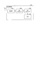
- FIG. 1 is a block diagram showing a configuration of a base station apparatus according to Embodiment 1.
- FIG. 2 is a block diagram showing the configuration of the terminal apparatus according to Embodiment 1.
- FIG. 3 is a flowchart showing a transmission process according to the first embodiment.
- FIG. 4 is a diagram illustrating a specific example of a subframe configuration according to Embodiment 1.
- FIG. 5 is a diagram illustrating a specific example of a subframe configuration according to Embodiment 2.
- FIG. 6 is a diagram illustrating a specific example of the subframe configuration according to Embodiment 3.
- FIG. 7 is a diagram illustrating a specific example of a subframe configuration according to Embodiment 4.
- FIG. 8 is a diagram illustrating a specific example of a subframe configuration according to Embodiment 5.
- FIG. 9 is a block diagram illustrating a hardware configuration example of the base station apparatus.
- FIG. 1 is a block diagram showing a configuration of base station apparatus 100 according to Embodiment 1.
- FIG. 1 includes an L-band receiving unit 101, a U-band receiving unit 102, CP (Cyclic Prefix) removing units 103 and 104, an FFT (Fast Fourier Transform) unit 105, 106, a channel separation unit 107, a decoding unit 108, and a U-band empty determination unit 109.
- These processing units are processing units on the receiving side of the base station apparatus 100.
- the base station apparatus 100 includes a U-band mapping unit 110, an L-band mapping unit 111, an EPDCCH generation unit 112, IFFT (Inverse Fast Fourier Transform) units 113 and 114, and CP addition units 115 and 116. , An L-band transmission unit 117 and a U-band transmission unit 118. These processing units are processing units on the transmission side of the base station apparatus 100.
- the L band receiving unit 101 receives an L band signal. That is, the L-band receiving unit 101 receives a signal in a frequency band that requires a license, such as a 2 GHz band.
- the U band receiving unit 102 receives a U band signal. That is, the U-band receiving unit 102 receives a signal in a frequency band that does not require a license, such as a 5 GHz band.
- CP removing sections 103 and 104 remove CPs added between OFDM (Orthogonal Frequency Division Multiplexing) symbols from L-band and U-band received signals, respectively.
- OFDM Orthogonal Frequency Division Multiplexing
- a CP for preventing intersymbol interference is added between OFDM symbols constituting a wireless signal, so that CP removing sections 103 and 104 remove this CP.
- the present invention is also applicable when wireless communication other than OFDM is performed. Therefore, when wireless communication other than the OFDM scheme is performed, the CP removing units 103 and 104 can be omitted.
- FFT sections 105 and 106 perform fast Fourier transform on L-band and U-band received signals, respectively, and acquire signals of a plurality of subcarriers having mutually orthogonal frequencies. That is, the FFT units 105 and 106 obtain signals of a plurality of subcarriers by converting time domain received signals into frequency domain signals. Note that the FFT units 105 and 106 are processing units that execute processing when OFDM wireless communication is performed, as with the CP removing units 103 and 104 described above, and therefore wireless communication other than OFDM is performed. Can be omitted.
- the channel separation unit 107 separates the signals of a plurality of subcarriers in the L band and the U band into signals for each channel. That is, since the signals of a plurality of channels are frequency-multiplexed and time-multiplexed in the L-band and U-band received signals, the channel separation unit 107 converts the received signals of each band into, for example, data channels and control for each terminal device. Separate into channel signals.
- the decoding unit 108 decodes each channel signal obtained by the channel separation unit 107 to obtain decoded data.
- the U-band availability determination unit 109 detects reception energy in the U-band channel when data to be transmitted using the U-band is generated, and determines whether or not the U-band is available. That is, the U-band availability determination unit 109 performs carrier sense when data to be transmitted using the U-band is generated. Specifically, the U-band availability determining unit 109 determines that the U-band is being used by another device when the received energy in the U-band is equal to or greater than a predetermined threshold. Also, the U band availability determination unit 109 determines that the U band is available when the received energy in the U band is less than a predetermined threshold.
- the U-band availability determination unit 109 continuously performs carrier sense continuously for a predetermined period. That is, even after the U-band availability determining unit 109 determines that the U-band is available, for example, between a predetermined time such as DIFS (Distributed Inter-Frame Space) and a back-off time randomly determined for each device. Execute carrier sense periodically continuously.
- DIFS Distributed Inter-Frame Space
- the U-band availability determining unit 109 When the U-band availability determining unit 109 continues to determine that the U-band is available during the DIFS and the back-off time, it is determined to transmit data using the U-band, and the U-band availability determining unit 109 determines that the U-band is available. Notify the band mapping unit 110. On the other hand, if it is determined that the U band is being used by another device during the DIFS and the back-off time, the U band empty determination unit 109 determines to postpone data transmission using the U band, The carrier sense is executed again after the elapse of time.
- the U-band mapping unit 110 uses a U-band DCI indicating downlink data allocation in the U-band as a component of the control channel when data to be transmitted using the U-band is generated. Map to Element Group). That is, the U-band mapping unit 110 generates U-band DCI that indicates which terminal device stores data addressed to each sub-band in the U-band.
- the U-band mapping unit 110 is notified from the U-band availability determination unit 109 that data is transmitted using the U-band, the U-band DCI mapped in advance to the REG is sent to the EPDCCH generation unit 112. Output.
- the U-band vacancy determination unit 109 does not notify that the data is transmitted using the U-band, the U-band mapping unit 110 temporarily outputs the U-band DCI mapped to the REG without outputting it. Hold on.
- U-band DCI in addition to the above-described DL (DownLink) assignment indicating downlink data allocation, UL for permitting terminal devices to transmit uplink using the U band. (UpLink) Grant may be included.
- the L-band mapping unit 111 maps the L-band DCI indicating the allocation of downlink data in the L band to the REG when data to be transmitted using the L band is generated. That is, the L-band mapping unit 111 generates L-band DCI indicating which terminal device stores data addressed to each sub-band in the L-band. Then, the L-band mapping unit 111 outputs the L-band DCI mapped to the REG to the EPDCCH generation unit 112 regardless of the presence or absence of data transmission using the U band.
- the EPDCCH generation unit 112 arranges the U-band DCI and the L-band DCI output from the U-band mapping unit 110 and the L-band mapping unit 111, respectively, in the L-band EPDCCH region. Specifically, EPDCCH generation section 112 assigns REGs to which U-band DCI and L-band DCI are mapped to subcarriers of different frequencies in the L-band EPDCCH region. Therefore, for example, even when the U-band mapping unit 110 does not output the U-band DCI and the L-band mapping unit 111 outputs the L-band DCI, the EPDCCH generation unit 112 independently generates the L-band DCI. It can be assigned to subcarriers in the EPDCCH region.
- EPDCCH generating section 112 then outputs U-band DCI and L-band DCI allocated to the L-band subcarriers together with data allocated to other sub-carriers in the L-band to IFFT section 113. In addition, EPDCCH generation section 112 outputs data assigned to U-band subcarriers to IFFT section 114.
- the IFFT units 113 and 114 perform inverse fast Fourier transform on the data for each subcarrier of the L band and the U band, respectively, and acquire time-domain OFDM symbols. That is, IFFT sections 113 and 114 obtain the OFDM symbol by converting the frequency domain data allocated to each subcarrier into a time domain signal.
- the IFFT units 113 and 114 are processing units that execute processing when wireless communication of the OFDM scheme is performed, similarly to the CP removal units 103 and 104 and the FFT units 105 and 106 described above. If wireless communication is performed, it can be omitted.
- CP adding sections 115 and 116 add a CP between L-band and U-band OFDM symbols, respectively, and generate L-band and U-band transmission signals.
- the CP adding units 115 and 116 are processing units for performing processing when OFDM wireless communication is performed, as with the IFFT units 113 and 114, wireless communication other than OFDM is performed. Can be omitted.
- the L band transmission unit 117 transmits an L band transmission signal. That is, the L-band transmission unit 117 transmits a transmission signal in a frequency band that requires a license, such as a 2 GHz band.
- the U band transmission unit 118 transmits a U band transmission signal. That is, the U-band transmission unit 118 transmits a transmission signal in a frequency band that does not require a license, such as a 5 GHz band.
- FIG. 2 is a block diagram showing a configuration of terminal apparatus 200 according to Embodiment 1.
- 2 includes an L-band receiving unit 201, a U-band receiving unit 202, CP removal units 203 and 204, FFT units 205 and 206, and a decoding unit 207.
- These processing units are processing units on the receiving side of the terminal device 200.
- the terminal device 200 includes a scheduler unit 208, an encoding unit 209, a channel multiplexing unit 210, IFFT units 211 and 212, CP adding units 213 and 214, an L band transmission unit 215, and a U band transmission unit 216.
- These processing units are processing units on the transmission side of the terminal device 200.
- the L band receiving unit 201 receives an L band signal. That is, the L-band receiving unit 201 receives a signal in a frequency band that requires a license, such as a 2 GHz band.
- the U band receiving unit 202 receives a U band signal. That is, the U band receiving unit 202 receives a signal in a frequency band that does not require a license, such as a 5 GHz band.
- CP removing sections 203 and 204 remove CPs added between OFDM symbols from L-band and U-band received signals, respectively.
- the CP removal units 203 and 204 are processing units that execute processing when wireless communication of the OFDM scheme is performed, similarly to the CP removal units 103 and 104 described above, and therefore wireless communication other than the OFDM scheme is performed. In some cases, it can be omitted.
- FFT sections 205 and 206 perform fast Fourier transform on the L-band and U-band received signals, respectively, and acquire signals of a plurality of subcarriers having frequencies orthogonal to each other.
- the FFT units 205 and 206 are processing units that execute processing when OFDM wireless communication is performed, as with the CP removing units 203 and 204 described above, and when wireless communication other than OFDM is performed. Can be omitted.
- the decoding unit 207 decodes the signals of a plurality of subcarriers in the L band and the U band, and obtains decoded data addressed to the terminal device 200. That is, decoding section 207 decodes signals assigned to subcarriers in the L-band EPDCCH region among a plurality of subcarrier signals to obtain L-band DCI and U-band DCI. Then, decoding section 207 decodes the subcarrier signal included in the subband allocated to terminal apparatus 200 among the subbands in the L band, with reference to Lband DCI. Similarly, decoding section 207 refers to U-band DCI and decodes subcarrier signals included in subbands allocated to terminal apparatus 200 among the subbands in the U band.
- the decoding unit 207 refers to the DL assignment included in the L-band DCI and the U-band DCI, and determines in which subband the data addressed to the terminal apparatus 200 is stored.
- Decoding section 207 outputs UL grant to scheduler section 208 when UL grant is included in U-band DCI.
- scheduler section 208 determines a subframe in which uplink data transmission is permitted based on the UL grant, and executes scheduling for transmitting data in this subframe. To do. Specifically, scheduler section 208 determines, for example, a subframe after a predetermined number of subframes from which the UL grant is received as a subframe in which uplink data transmission is permitted.
- the encoding unit 209 encodes uplink transmission data according to the scheduling in the scheduler unit 208. Then, encoding section 209 outputs the obtained encoded data to channel multiplexing section 210.
- the channel multiplexing unit 210 frequency-multiplexes and time-multiplexes the encoded data output from the encoding unit 209 and, for example, an uplink channel quality measurement reference signal, and assigns them to each channel of the L band and the U band. That is, channel multiplexing section 210 allocates encoded data and reference signals to a plurality of subcarriers and a plurality of subframes in the L band and the U band.
- IFFT sections 211 and 212 perform inverse fast Fourier transform on the data for each subcarrier of the L band and U band, respectively, and acquire time-domain OFDM symbols. That is, IFFT sections 211 and 212 obtain OFDM symbols by converting frequency domain data allocated to each subcarrier into time domain signals.
- IFFT units 211 and 212 are processing units that perform processing when OFDM wireless communication is performed, as with CP removing units 203 and 204 and FFT units 205 and 206 described above. If wireless communication is performed, it can be omitted.
- CP adding sections 213 and 214 add CPs between L-band and U-band OFDM symbols, respectively, and generate L-band and U-band transmission signals.
- the CP adding units 213 and 214 are processing units that execute processing when OFDM wireless communication is performed, similarly to the IFFT units 211 and 212, wireless communication other than OFDM is performed. Can be omitted.
- the L-band transmission unit 215 transmits an L-band transmission signal.
- the L-band transmission unit 215 transmits a transmission signal in a frequency band that requires a license, such as a 2 GHz band.
- the U-band transmission unit 216 transmits a U-band transmission signal. That is, the U-band transmission unit 216 transmits a transmission signal in a frequency band that does not require a license, such as a 5 GHz band.
- DCI including a DL assignment indicating an allocation position of the data in the downlink is generated.
- the L band DCI indicating the subband in the L band to which each data is allocated is mapped to the REG by the L band mapping unit 111 ( Step S101).
- U band DCI indicating the subband in the U band to which each data is allocated is mapped to REG by the U band mapping unit 110 (step S102). ).
- DCI mappings may be executed at an arbitrary timing before the timing at which the DCI is actually transmitted. That is, for example, when data to be transmitted is generated, mapping of each DCI may be executed immediately.
- mapping of each DCI since the L-band DCI and the U-band DCI are mapped to the REG independently of each other, when data is transmitted using only the L band or only the U band, it corresponds to the band to be used.
- One DCI may be mapped to REG.
- the description will be continued assuming that data is transmitted using both the L band and the U band.
- carrier sense is executed by the U band availability determination unit 109 in parallel with the mapping of the U band DCI. That is, the reception energy of the received signal received by the U-band receiving unit 102 is detected by the U-band availability determining unit 109, and it is determined whether or not the U-band is available (step S103). Specifically, when the received energy in the U band is equal to or greater than a predetermined threshold, it is determined that another device is transmitting and the U band is not free, and the received energy in the U band is less than the predetermined threshold. In this case, it is determined that there is no transmitting device and the U band is free.
- the U band DCI mapped by the U band mapping unit 110 is output to the EPDCCH generation unit 112.
- the L-band DCI mapped by the L-band mapping unit 111 is output to the EPDCCH generation unit 112 as needed regardless of the result of the determination by the U-band empty determination unit 109.
- the EPDCCH generation unit 112 arranges the U-band DCI and the L-band DCI in the L-band EPDCCH region. Specifically, REGs to which U-band DCI and L-band DCI are mapped are allocated to subcarriers of different frequencies in the L-band EPDCCH region. As a result, an EPDCCH in which the U-band DCI and the L-band DCI are arranged at different frequencies is generated (step S104).
- the U band DCI mapped by the U band mapping unit 110 is retained as it is (step S105).
- the L-band DCI mapped by the L-band mapping unit 111 is output to the EPDCCH generation unit 112 as needed regardless of the result of the determination by the U-band empty determination unit 109.
- the EPDCCH generation unit 112 arranges the L-band DCI within the L-band EPDCCH region. Specifically, a REG to which L-band DCI is mapped is assigned to a subcarrier in the L-band EPDCCH region. Thereby, EPDCCH including L band DCI is generated (step S106).
- the L-band DCI and the U-band DCI are arranged at different frequencies in the EPDCCH region, the L-band DCI is independently arranged in the EPDCCH regardless of whether or not the U-band DCI is transmitted. can do.
- the U-band DCI is retained even when the U-band is not available, when the U-band is available, the retained U-band DCI can be arranged in the EPDCCH as it is.
- the L-band DCI and the U-band DCI are mapped in advance, and the EPDCCH can be generated in a short time.
- the L-band DCI and the U-band DCI allocated to the subcarriers constituting the L-band EPDCCH are output to the IFFT unit 113 together with the data allocated to the other subcarriers in the L-band according to the L-band DCI. Also, data allocated to each U-band subcarrier according to U-band DCI is output to IFFT section 114. Then, IFFT sections 113 and 114 perform inverse fast Fourier transform on the data allocated to each subcarrier (step S107), and generate L-band and U-band OFDM symbols, respectively.
- CPs are added to the generated OFDM symbols by the CP adding units 115 and 116 (step S108), and the obtained transmission signals are transmitted from the L band transmitting unit 117 and the U band transmitting unit 118, respectively (step S109). .
- the signal transmitted from the base station apparatus 100 is received by the terminal apparatus 200, and the decoding unit 207 decodes the L-band EPDCCH, so that the subcarriers to which the data addressed to the terminal apparatus 200 is allocated can be grasped. That is, the position of data addressed to terminal device 200 in the L band is determined from the DCI for L band of EPDCCH, and the position of data addressed to terminal device 200 in the U band is determined from DCI for U band of EPDCCH. Then, the data destined for the terminal device 200 in the L band and the U band is decoded by the decoding unit 207.
- the scheduler unit 208 executes uplink scheduling according to the UL grant.
- FIG. 4 is a diagram showing data transmitted using each frequency band of the L band and the U band in time series.
- data 301 in which data addressed to three terminal apparatuses UE # 1 to UE # 3 is frequency-multiplexed is transmitted by the base station apparatus.
- the DL assignment 302 related to the data 301 is transmitted in the same subframe as each data.
- the DL assignment 302 is L-band DCI, and is transmitted, for example, arranged at a frequency in the EPDCCH region.
- Each of the terminal devices UE # 1 to UE # 3 can receive and decode the DL assignment 302 in the EPDCCH region, thereby grasping which subband in the L band the data addressed to itself is assigned. it can.
- U-band DCI is arranged and transmitted at a frequency different from the frequency at which DL assignment 302 in the L-band EPDCCH region is arranged. That is, the DL assignment 303 and UL grant 304 related to the U band are arranged at frequencies in the EPDCCH region.
- Each of the terminal apparatuses UE # 1 to UE # 3 receives and decodes the DL assignment 303 in the EPDCCH region, so that each terminal apparatus UE # 1 to # 3 can grasp to which subband in the U band the data addressed to itself is assigned. it can. Also, the terminal apparatuses UE # 1 to # 3 can recognize whether or not the uplink data transmission using the U band is permitted by receiving and decoding the UL grant 304 in the EPDCCH region.
- the L-band DCI 302 and the U-band DCIs 303 and 304 are arranged at different frequencies and transmitted. For this reason, the base station apparatus maps the L-band DCI 302 and the U-band DCIs 303 and 304 in advance, and transmits only the L-band DCI 302 or transmits both bands of DCI according to the result of carrier sense. Can be.
- the U-band frequency band may be occupied by the transmission of data 351 by a wireless LAN.
- the base station apparatus when data to be transmitted is generated from the base station apparatus using the U band, the base station apparatus periodically detects reception energy in the U band and determines whether or not the U band is free.
- the periodic carrier sense is continued even during a predetermined DIFS, and the back-off is randomly determined for each base station apparatus. Continue your career sense for hours.
- the base station apparatus transmits a dummy signal 352 to the head of the next subframe.
- the dummy signal 352 is a signal that occupies the U-band frequency band, and is transmitted to reserve the use of the U-band. That is, the dummy signal 352 is transmitted in the U band in order to prevent the other device from performing carrier sense to determine that the U band is free.
- data 353 in which data addressed to the terminal apparatuses UE # 1 to # 3 is frequency-multiplexed is transmitted by the base station apparatus.
- the DL assignment 303 related to the data 353 is transmitted in the same subframe as each data using the L-band EPDCCH.
- a special subframe 354 is provided after the subframe in which the downlink data 353 is transmitted, and the uplink data 355 is transmitted in a subframe after the special subframe 354.
- Uplink data 355 is scheduled by terminal apparatuses UE # 1 to UE # 3 using UL grant 304 transmitted using the L-band EPDCCH, and is transmitted according to this scheduling.
- L-band DCI and U-band DCI are arranged and transmitted at different frequencies in the L-band EPDCCH region. For this reason, even if transmission of data using the U band is postponed as a result of carrier sense, the L-band DCI mapped in advance can be transmitted independently of the U-band DCI. Also, the U-band DCI mapped in advance can be temporarily held, and when the data transmission using the U-band is executed as a result of carrier sense, the held U-band DCI can be transmitted. . Therefore, control information can be efficiently transmitted when communication is performed using a frequency band that requires a license and a frequency band that does not require a license.
- the example in which the L-band DCI and the U-band DCI are arranged at different frequencies in the L-band EPDCCH region is shown. However, the same effect can be obtained if they are arranged in different regions. Obtainable.
- a feature of the second embodiment is that a DL assignment indicating assignment of downlink data in the U band and a UL grant indicating permission for transmission of uplink data in the U band are arranged at different frequencies.
- the configurations of the base station apparatus and terminal apparatus according to Embodiment 2 are the same as those of base station apparatus 100 and terminal apparatus 200 according to Embodiment 1, description thereof is omitted.
- the operation of the EPDCCH generation unit 112 of the base station apparatus 100 is different from that of the first embodiment.
- the EPDCCH generation unit 112 arranges the U-band DCI and the L-band DCI output from the U-band mapping unit 110 and the L-band mapping unit 111, respectively, in the L-band EPDCCH region. At this time, the EPDCCH generation unit 112 assigns the REG on which the U-band DCI and the L-band DCI are mapped to subcarriers having different frequencies in the L-band EPDCCH region. Furthermore, EPDCCH generation section 112 assigns REGs, in which DL assignments and UL grants, are mapped in U-band DCI to subcarriers of different frequencies in the L-band EPDCCH region.
- the L-band DCI, the U-band DL assignment, and the U-band UL grant are arranged at mutually different frequencies. Therefore, for example, even when the U band DL grant is output without the U band UL grant being output from the U band mapping unit 110, the EPDCCH generation unit 112 is configured to output the L band DCI and the U band. DL assignments can be assigned to subcarriers in the EPDCCH region.
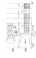
- FIG. 5 is a diagram showing data transmitted using each frequency band of the L band and the U band in time series. 5, the same parts as those in FIG. 4 are denoted by the same reference numerals, and detailed description thereof is omitted.
- data 301 in which data addressed to three terminal apparatuses UE # 1 to UE # 3 are frequency-multiplexed and DL assignment 302 related to data 301 are transmitted.
- U-band DL assignment 401 and UL grant 402 are arranged and transmitted at a frequency different from the frequency at which DL assignment 302 in the L-band EPDCCH region is arranged. That is, DL assignment 401 and UL grant 402 are arranged at different frequencies in the EPDCCH region.
- Each of the terminal apparatuses UE # 1 to # 3 receives and decodes the DL assignment 401 in the EPDCCH region, so that each terminal apparatus UE # 1 to # 3 can grasp to which subband in the U band the data addressed to itself is assigned. it can. Also, the terminal apparatuses UE # 1 to # 3 can recognize whether or not the uplink data transmission using the U band is permitted by receiving and decoding the UL grant 402 in the EPDCCH region.
- the L-band DCI 302, the U-band DL assignment 401, and the U-band UL grant 402 are arranged at different frequencies and transmitted.
- the base station apparatus maps the L-band DCI 302, the U-band DL assignment 401, and the U-band UL grant 402 in advance, and uses only the L-band DCI 302 according to the result of carrier sense. It is possible to transmit or transmit DCI of both bands. Further, for example, when downlink data is transmitted in the U band, but uplink data transmission in the U band is not permitted, the base station apparatus transmits only the DL assignment 401 of the UCI DCI. You can also. The base station apparatus temporarily holds the UL grant 402 mapped in advance, and can transmit the held UL grant 402 when uplink data transmission in the U band is permitted.
- L-band DCI and U-band DCI are arranged and transmitted at different frequencies in the L-band EPDCCH region.
- the DL assignment and the UL grant in the U-band DCI are also arranged and transmitted at different frequencies in the L-band EPDCCH region. Therefore, as a result of carrier sense, for example, downlink data transmission using U band is executed, but even when uplink data transmission is not executed, a pre-mapped DL assignment is transmitted independently of UL grant. can do. Further, when the UL grant mapped in advance is temporarily held, and the uplink data transmission using the U band is executed as a result of the carrier sense, the held UL grant can be transmitted. Therefore, control information can be efficiently transmitted when communication is performed using a frequency band that requires a license and a frequency band that does not require a license.
- the example in which the DL assignment and the UL grant included in the L-band DCI and the U-band DCI are arranged at different frequencies in the L-band EPDCCH region has been described. The same effect can be obtained as long as it is arranged.
- a feature of the third embodiment is that an UL grant indicating permission for transmission of uplink data in the U band is arranged in the U band.
- the configurations of the base station apparatus and terminal apparatus according to Embodiment 3 are the same as those of base station apparatus 100 and terminal apparatus 200 according to Embodiment 1, description thereof is omitted.
- the operation of the EPDCCH generation unit 112 of the base station apparatus 100 is different from that in the first embodiment.
- the EPDCCH generation unit 112 outputs the U-band DCI and the L-band DCI output from the U-band mapping unit 110 and the L-band mapping unit 111, respectively, in the L-band EPDCCH region and the U-band predetermined control channel region. Place in. At this time, the EPDCCH generation unit 112 converts the REG to which the DL assignment is mapped out of the U-band DCI and the REG to which the L-band DCI is mapped into subcarriers having different frequencies in the L-band EPDCCH region. assign. In addition, EPDCCH generation section 112 allocates REG to which UL grant is mapped in Uband DCI to subcarriers in a predetermined control channel region of U band.
- the L-band DCI, the U-band DL assignment, and the U-band UL grant are arranged at mutually different frequencies.
- the UL grant for the U band is arranged not at a frequency in the EPDCCH region of the L band but at a frequency in a predetermined control channel region of the U band. Therefore, it is possible to reduce resources used in the L-band EPDCCH that requires a license and reduce overhead.
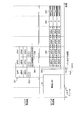
- FIG. 6 is a diagram showing data transmitted using each frequency band of the L band and the U band in time series. 6, the same parts as those in FIGS. 4 and 5 are denoted by the same reference numerals, and detailed description thereof is omitted.
- a U-band DL assignment 401 is arranged and transmitted at a frequency different from the frequency at which the DL assignment 302 in the L-band EPDCCH region is arranged.
- a U-band UL grant 501 is arranged and transmitted at a frequency within a predetermined control channel region of the U-band. That is, the UL grant 501 is arranged not in the L-band EPDCCH region but in the U-band.
- Each of the terminal apparatuses UE # 1 to # 3 receives and decodes the DL assignment 401 in the EPDCCH region, so that each terminal apparatus UE # 1 to # 3 can grasp to which subband in the U band the data addressed to itself is assigned. it can. Also, the terminal devices UE # 1 to UE # 3 receive and decode the UL grant 501 in a predetermined control channel region of the U band, thereby grasping the presence / absence of permission for uplink data transmission using the U band. can do.
- the base station apparatus maps the L-band DCI 302, the U-band DL assignment 401, and the U-band UL grant 501 in advance, and uses only the L-band DCI 302 according to the result of carrier sense. It is possible to transmit or transmit DCI of both bands. Further, for example, when downlink data is transmitted in the U band, but uplink data transmission in the U band is not permitted, the base station apparatus transmits only the DL assignment 401 of the UCI DCI. You can also. The base station apparatus temporarily holds the UL grant 501 mapped in advance, and transmits the held UL grant 501 using the U band when uplink data transmission in the U band is permitted. can do.
- L-band DCI and U-band DCI are arranged and transmitted at different frequencies in the L-band EPDCCH region and the U-band predetermined control channel region.
- the UL grant in the U-band DCI is arranged and transmitted in a predetermined control channel region of the U band. For this reason, DCI arranged in the L-band EPDCCH region can be reduced, and overhead in EPDCCH can be reduced.
- the example in which the DL assignments included in the L-band DCI and the U-band DCI are arranged at different frequencies in the L-band EPDCCH region has been described. If so, the same effect can be obtained.
- a feature of the fourth embodiment is that DL assignment indicating allocation of downlink data in the U band and UL grant indicating permission for transmission of uplink data in the U band are arranged at different frequencies in the U band. is there.
- the EPDCCH generation unit 112 outputs the U-band DCI and the L-band DCI output from the U-band mapping unit 110 and the L-band mapping unit 111, respectively, in the L-band EPDCCH region and the U-band predetermined control channel region. Place in. At this time, EPDCCH generation section 112 assigns REG to which L-band DCI is mapped to subcarriers in the L-band EPDCCH region. Also, the EPDCCH generation unit 112 allocates REGs mapped with U-band DCI to subcarriers having different frequencies in a predetermined control channel region of the U band. That is, the EPDCCH generation unit 112 arranges the DL assignment and UL grant in the U band at different frequencies in a predetermined control channel region of the U band.
- L-band DCI is arranged in the L band, while U-band DCI is arranged in the U band.
- the DL assignment and UL grant included in the U-band DCI are arranged at different frequencies within a predetermined control channel region. Therefore, it is possible to reduce resources used in the L-band EPDCCH that requires a license and reduce overhead.
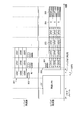
- FIG. 7 is a diagram showing, in time series, data transmitted using each frequency band of the L band and the U band. 7, the same parts as those in FIG. 4 are denoted by the same reference numerals, and detailed description thereof is omitted.
- data 301 in which data addressed to three terminal apparatuses UE # 1 to UE # 3 are frequency-multiplexed and DL assignment 302 related to data 301 are transmitted.
- the DL assignment 302 is arranged and transmitted in the L-band EPDCCH region.
- U-band DCI is arranged and transmitted at a frequency within a predetermined control channel region of U-band.
- U-band DL assignment 601 and UL grant 602 are transmitted at different frequencies in a predetermined control channel region of U-band. That is, the DL assignment 601 and the UL grant 602 are arranged in the U band, not in the L band EPDCCH region.
- Each of the terminal apparatuses UE # 1 to # 3 receives and decodes the DL assignment 601 in the predetermined control channel region of the U band, so that the data addressed to itself is assigned to which subband in the U band. You can figure out what you are doing.
- the terminal apparatuses UE # 1 to # 3 receive and decode the UL grant 602 in a predetermined control channel region of the U band, thereby grasping the presence / absence of permission for uplink data transmission using the U band. can do.
- the L-band DCI 302 is arranged and transmitted in the L-band EPDCCH region, and the U-band DL assignment 601 and the UL grant 602 are mutually connected in the predetermined control channel region of the U-band. It is transmitted at different frequencies. For this reason, the base station apparatus maps the L-band DCI 302, the U-band DL assignment 601 and the U-band UL grant 602 in advance, and performs only the L-band DCI 302 according to the carrier sense result. It is possible to transmit or transmit DCI of both bands. Further, for example, when downlink data is transmitted in the U band but uplink data transmission in the U band is not permitted, the base station apparatus transmits only the DL assignment 601 in the UCI DCI. You can also. Then, the base station apparatus temporarily holds the UL grant 602 mapped in advance, and when the uplink data transmission in the U band is permitted, transmits the held UL grant 602 using the U band. can do.
- L-band DCI and U-band DCI are arranged and transmitted at different frequencies in the L-band EPDCCH region and the U-band predetermined control channel region. Also, the DL assignment and the UL grant included in the U-band DCI are arranged and transmitted at different frequencies within a predetermined control channel region of the U-band. For this reason, DCI arranged in the L-band EPDCCH region can be reduced, and overhead in EPDCCH can be reduced.
- the example in which the DL assignment and the UL grant included in the U-band DCI are arranged at different frequencies within a predetermined control channel area of the U band has been described. If it is done, the same effect can be obtained.
- a feature of the fifth embodiment is that a DL assignment indicating assignment of downlink data in the U band and a UL grant indicating permission for transmission of uplink data in the U band are arranged at the same frequency in the U band. It is.
- the EPDCCH generation unit 112 outputs the U-band DCI and the L-band DCI output from the U-band mapping unit 110 and the L-band mapping unit 111, respectively, in the L-band EPDCCH region and the U-band predetermined control channel region. Place in. At this time, EPDCCH generation section 112 assigns REG to which L-band DCI is mapped to subcarriers in the L-band EPDCCH region. Also, the EPDCCH generation unit 112 assigns the REG mapped with the U-band DCI to subcarriers in a predetermined control channel region of the U band. That is, the EPDCCH generation unit 112 time-multiplexes the DL assignment and UL grant in the U band and arranges them at the same frequency within a predetermined control channel region of the U band.
- the L-band DCI is arranged in the L-band, while the U-band DCI is arranged in the U-band.
- the DL assignment and UL grant included in the U-band DCI are time-multiplexed and arranged at the same frequency within a predetermined control channel region. Therefore, it is possible to reduce resources used in the L-band EPDCCH that requires a license and reduce overhead.
- the terminal apparatus decodes the U-band DCI at one frequency within a predetermined control channel region of the U-band, thereby grasping the downlink data allocation position and the presence / absence of uplink transmission permission. Can do.
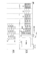
- FIG. 8 is a diagram showing, in time series, data transmitted using each frequency band of the L band and the U band. 8, the same parts as those in FIG. 4 are denoted by the same reference numerals, and detailed description thereof is omitted.
- data 301 in which data addressed to three terminal apparatuses UE # 1 to UE # 3 are frequency-multiplexed and DL assignment 302 related to data 301 are transmitted.
- the DL assignment 302 is arranged and transmitted in the L-band EPDCCH region.
- U-band DCI is arranged and transmitted at a frequency within a predetermined control channel region of U-band.
- the DL assignment 701 for U band and the UL grant 702 are time-multiplexed, arranged at the same frequency within a predetermined control channel region of the U band, and transmitted. That is, the DL assignment 701 and the UL grant 702 are arranged in the U band, not in the L band EPDCCH region.
- Each of the terminal apparatuses UE # 1 to # 3 receives and decodes the DL assignment 701 in the predetermined control channel region of the U band, so that the data addressed to itself is assigned to which subband in the U band. You can figure out what you are doing.
- the terminal devices UE # 1 to UE # 3 receive and decode the UL grant 702 in a predetermined control channel region of the U band, thereby grasping whether or not the uplink data transmission using the U band is permitted. can do.
- the L-band DCI 302 is arranged and transmitted in the L-band EPDCCH region, and the U-band DL assignment 701 and the UL grant 702 are the same in the predetermined control channel region in the U-band. It is arranged at the frequency of and is transmitted. For this reason, the base station apparatus maps in advance the L-band DCI 302, the U-band DL assignment 701, and the U-band UL grant 702, and uses only the L-band DCI 302 according to the carrier sense result. It is possible to transmit or transmit DCI of both bands. That is, for example, when the U-band is not free as a result of carrier sense, the base station apparatus can transmit only the L-band DCI 302.
- the base station apparatus temporarily holds the DL assignment 701 and UL grant 702 for U band that are mapped in advance, and when the U band is free, the DL assignment 701 and UL grant 702 that are held are stored. It can be transmitted using the U band.
- L-band DCI and U-band DCI are arranged and transmitted at different frequencies in the L-band EPDCCH region and the U-band predetermined control channel region. Also, the DL assignment and UL grant included in the U-band DCI are arranged and transmitted at the same frequency within a predetermined control channel region of the U band. For this reason, DCI arranged in the L-band EPDCCH region can be reduced, and overhead in EPDCCH can be reduced. Also, the terminal device can decode the DL assignment and the UL grant from one frequency of the U band.
- the DL assignment and UL grant included in the U-band DCI are arranged at the same frequency within a predetermined control channel region of the U band. The same effect can be obtained as long as it is arranged.
- a base station apparatus 800 illustrated in FIG. 9 includes a wireless unit 801, a baseband processor (hereinafter abbreviated as “BB processor”) 802, an application processor (hereinafter abbreviated as “AP processor”) 803, and a memory 804.
- BB processor baseband processor
- AP processor application processor
- the wireless unit 801 transmits a wireless signal including DCI via an antenna.
- the wireless unit 801 receives a wireless signal via an antenna.
- the wireless unit 801 executes a predetermined wireless transmission process or a predetermined wireless reception process.
- the radio unit 801 corresponds to, for example, the L band receiving unit 101, the U band receiving unit 102, the L band transmitting unit 117, and the U band transmitting unit 118 of the base station apparatus 100 illustrated in FIG.
- the BB processor 802 performs baseband processing on transmitted / received signals. That is, the BB processor 802 executes, for example, signal modulation / demodulation and encoding / decoding.
- the BB processor 802 includes, for example, the CP removal units 103 and 104, the FFT units 105 and 106, the channel separation unit 107, the decoding unit 108, the U-band empty determination unit 109, and the U-band mapping unit of the base station apparatus 100 illustrated in FIG. 110, an L-band mapping unit 111, an EPDCCH generation unit 112, IFFT units 113 and 114, and CP addition units 115 and 116.
- the AP processor 803 executes application processing. That is, the AP processor 803 executes processing using the decoded data obtained in the BB processor 802 and executes processing for determining the contents of DCI.
- the memory 804 stores data used when the AP processor 803 executes processing.
Abstract
Description
図1は、実施の形態1に係る基地局装置100の構成を示すブロック図である。図1に示す基地局装置100は、Lバンド受信部101、Uバンド受信部102、CP(Cyclic Prefix:サイクリックプレフィックス)除去部103、104、FFT(Fast Fourier Transform:高速フーリエ変換)部105、106、チャネル分離部107、復号部108及びUバンド空き判断部109を有する。これらの処理部は、基地局装置100の受信側の処理部である。また、基地局装置100は、Uバンド用マッピング部110、Lバンド用マッピング部111、EPDCCH生成部112、IFFT(Inverse Fast Fourier Transform:逆高速フーリエ変換)部113、114、CP付加部115、116、Lバンド送信部117及びUバンド送信部118を有する。これらの処理部は、基地局装置100の送信側の処理部である。
実施の形態2の特徴は、Uバンドにおける下り回線のデータの割り当てを示すDLアサインメントとUバンドにおける上り回線のデータの送信許可を示すULグラントとを異なる周波数に配置する点である。
実施の形態3の特徴は、Uバンドにおける上り回線のデータの送信許可を示すULグラントをUバンドに配置する点である。
実施の形態4の特徴は、Uバンドにおける下り回線のデータの割り当てを示すDLアサインメントとUバンドにおける上り回線のデータの送信許可を示すULグラントとをUバンド内の異なる周波数に配置する点である。
実施の形態5の特徴は、Uバンドにおける下り回線のデータの割り当てを示すDLアサインメントとUバンドにおける上り回線のデータの送信許可を示すULグラントとをUバンド内の同一の周波数に配置する点である。
102、202 Uバンド受信部
103、104、203、204 CP除去部
105、106、205、206 FFT部
107 チャネル分離部
108、207 復号部
109 Uバンド空き判断部
110 Uバンド用マッピング部
111 Lバンド用マッピング部
112 EPDCCH生成部
113、114、211、212 IFFT部
115、116、213、214 CP付加部
117、215 Lバンド送信部
118、216 Uバンド送信部
208 スケジューラ部
209 符号化部
210 チャネル多重部
Claims (14)
- 基地局装置と端末装置を有する無線通信システムであって、
前記基地局装置は、
他の無線通信システムにおける通信との干渉が発生しない第1の周波数帯域に関する第1の制御情報をマッピングする第1のマッピング部と、
他の無線通信システムにおける通信との干渉が発生し得る第2の周波数帯域に関する第2の制御情報をマッピングする第2のマッピング部と、
前記第1の制御情報と前記第2の制御情報を互いに異なる領域に配置して制御チャネル信号を生成する生成部と、
前記生成部によって生成された制御チャネル信号を前記端末装置へ送信する送信部と
を有することを特徴とする無線通信システム。 - 前記基地局装置は、
前記第2の周波数帯域が空いているか否かを判断する判断部をさらに有し、
前記生成部は、
前記判断部によって前記第2の周波数帯域が空いていると判断された場合に、前記第1の制御情報と前記第2の制御情報を互いに異なる領域に配置して制御チャネル信号を生成し、前記判断部によって前記第2の周波数帯域が空いていないと判断された場合に、前記第1の制御情報を用いて制御チャネル信号を生成する
ことを特徴とする請求項1記載の無線通信システム。 - 前記第2のマッピング部は、
前記判断部によって前記第2の周波数帯域が空いていないと判断された場合に、マッピングされた第2の制御情報を保持することを特徴とする請求項2記載の無線通信システム。 - 前記生成部は、
前記第1の制御情報と前記第2の制御情報を前記第1の周波数帯域の制御チャネル領域内の互いに異なる領域に配置して制御チャネル信号を生成することを特徴とする請求項1記載の無線通信システム。 - 前記生成部は、
前記第1の制御情報を前記第1の周波数帯域の制御チャネル領域内に配置し、前記第2の制御情報を前記第2の周波数帯域の制御チャネル領域内に配置して制御チャネル信号を生成することを特徴とする請求項1記載の無線通信システム。 - 前記第2のマッピング部は、
前記第2の周波数帯域における下り回線のデータ割り当てを示す下り回線制御情報と、前記第2の周波数帯域における上り回線のデータ送信の許可の有無を示す上り回線制御情報とをマッピングし、
前記生成部は、
前記下り回線制御情報及び前記上り回線制御情報を前記第1の制御情報が配置される領域とは異なる領域に配置して制御チャネル信号を生成する
ことを特徴とする請求項1記載の無線通信システム。 - 前記生成部は、
前記下り回線制御情報及び前記上り回線制御情報を前記第1の周波数帯域の制御チャネル領域内の同一の領域に配置して制御チャネル信号を生成することを特徴とする請求項6記載の無線通信システム。 - 前記生成部は、
前記下り回線制御情報及び前記上り回線制御情報を前記第1の周波数帯域の制御チャネル領域内の互いに異なる領域に配置して制御チャネル信号を生成することを特徴とする請求項6記載の無線通信システム。 - 前記生成部は、
前記下り回線制御情報を前記第1の周波数帯域の制御チャネル領域内に配置し、前記上り回線制御情報を前記第2の周波数帯域の制御チャネル領域内に配置して制御チャネル信号を生成することを特徴とする請求項6記載の無線通信システム。 - 前記生成部は、
前記下り回線制御情報及び前記上り回線制御情報を前記第2の周波数帯域の制御チャネル領域内の同一の領域に配置して制御チャネル信号を生成することを特徴とする請求項6記載の無線通信システム。 - 前記生成部は、
前記下り回線制御情報及び前記上り回線制御情報を前記第2の周波数帯域の制御チャネル領域内の互いに異なる領域に配置して制御チャネル信号を生成することを特徴とする請求項6記載の無線通信システム。 - 自装置が属する無線通信システムとは異なる他の無線通信システムにおける通信との干渉が発生しない第1の周波数帯域に関する第1の制御情報をマッピングする第1のマッピング部と、
前記他の無線通信システムにおける通信との干渉が発生し得る第2の周波数帯域に関する第2の制御情報をマッピングする第2のマッピング部と、
前記第1の制御情報と前記第2の制御情報を互いに異なる領域に配置して制御チャネル信号を生成する生成部と、
前記生成部によって生成された制御チャネル信号を送信する送信部と
を有することを特徴とする基地局装置。 - 自装置が属する無線通信システムとは異なる他の無線通信システムにおける通信との干渉が発生しない第1の周波数帯域に関する第1の制御情報と、前記他の無線通信システムにおける通信との干渉が発生し得る第2の周波数帯域に関する第2の制御情報とが互いに異なる領域に配置された制御チャネル信号を受信する受信部と、
前記受信部によって受信された制御チャネル信号を復号し、復号結果に基づいて、前記第1の周波数帯域及び前記第2の周波数帯域において受信されるデータを復号する復号部と
を有することを特徴とする端末装置。 - 無線通信システムに属する基地局装置における送信方法であって、
前記基地局装置が属する無線通信システムとは異なる他の無線通信システムにおける通信との干渉が発生しない第1の周波数帯域に関する第1の制御情報をマッピングし、
前記他の無線通信システムにおける通信との干渉が発生し得る第2の周波数帯域に関する第2の制御情報をマッピングし、
前記第1の制御情報と前記第2の制御情報を互いに異なる領域に配置して制御チャネル信号を生成し、
生成された制御チャネル信号を送信する
処理を有することを特徴とする送信方法。
Priority Applications (11)
| Application Number | Priority Date | Filing Date | Title |
|---|---|---|---|
| PCT/JP2014/079374 WO2016071976A1 (ja) | 2014-11-05 | 2014-11-05 | 無線通信システム、基地局装置、端末装置及び送信方法 |
| JP2016557387A JP6455521B2 (ja) | 2014-11-05 | 2014-11-05 | 無線通信システム、基地局装置、端末装置及び送信方法 |
| CA2965947A CA2965947A1 (en) | 2014-11-05 | 2014-11-05 | Wireless communication system, base station apparatus, terminal device, and transmission method |
| EP14905386.0A EP3217743B1 (en) | 2014-11-05 | 2014-11-05 | Wireless communication system, base station device, terminal device and transmission method |
| KR1020177011368A KR101998001B1 (ko) | 2014-11-05 | 2014-11-05 | 무선 통신 시스템, 기지국 장치, 단말 장치 및 송신 방법 |
| RU2017114657A RU2659480C1 (ru) | 2014-11-05 | 2014-11-05 | Система беспроводной связи, аппарат базовой станции, терминальное устройство и способ передачи |
| BR112017008230-6A BR112017008230A2 (pt) | 2014-11-05 | 2014-11-05 | sistema de comunicação sem fio, dispositivo de estação base, dispositivo terminal e método de transmissão |
| CN201480083178.5A CN107079425B (zh) | 2014-11-05 | 2014-11-05 | 无线通信系统、基站装置、终端装置和发送方法 |
| MX2017005523A MX358707B (es) | 2014-11-05 | 2014-11-05 | Sistema de comunicacion inalambrica, aparato de estacion base, dispositivo terminal y metodo de transmision. |
| AU2014410902A AU2014410902B2 (en) | 2014-11-05 | 2014-11-05 | Wireless communication system, base station device, terminal device and transmission method |
| US15/485,649 US9942915B2 (en) | 2014-11-05 | 2017-04-12 | Wireless communication system, base station apparatus, terminal device, and transmission method |
Applications Claiming Priority (1)
| Application Number | Priority Date | Filing Date | Title |
|---|---|---|---|
| PCT/JP2014/079374 WO2016071976A1 (ja) | 2014-11-05 | 2014-11-05 | 無線通信システム、基地局装置、端末装置及び送信方法 |
Related Child Applications (1)
| Application Number | Title | Priority Date | Filing Date |
|---|---|---|---|
| US15/485,649 Continuation US9942915B2 (en) | 2014-11-05 | 2017-04-12 | Wireless communication system, base station apparatus, terminal device, and transmission method |
Publications (1)
| Publication Number | Publication Date |
|---|---|
| WO2016071976A1 true WO2016071976A1 (ja) | 2016-05-12 |
Family
ID=55908729
Family Applications (1)
| Application Number | Title | Priority Date | Filing Date |
|---|---|---|---|
| PCT/JP2014/079374 WO2016071976A1 (ja) | 2014-11-05 | 2014-11-05 | 無線通信システム、基地局装置、端末装置及び送信方法 |
Country Status (11)
| Country | Link |
|---|---|
| US (1) | US9942915B2 (ja) |
| EP (1) | EP3217743B1 (ja) |
| JP (1) | JP6455521B2 (ja) |
| KR (1) | KR101998001B1 (ja) |
| CN (1) | CN107079425B (ja) |
| AU (1) | AU2014410902B2 (ja) |
| BR (1) | BR112017008230A2 (ja) |
| CA (1) | CA2965947A1 (ja) |
| MX (1) | MX358707B (ja) |
| RU (1) | RU2659480C1 (ja) |
| WO (1) | WO2016071976A1 (ja) |
Families Citing this family (5)
| Publication number | Priority date | Publication date | Assignee | Title |
|---|---|---|---|---|
| KR100466123B1 (ko) * | 2002-10-16 | 2005-01-13 | 현대자동차주식회사 | 차량의 브레이크패드의 분진 여과 장치 |
| US11187288B2 (en) * | 2019-07-31 | 2021-11-30 | Federal-Mogul Motorparts Llc | Vehicle brake component for collecting brake dust |
| KR102261576B1 (ko) * | 2019-12-31 | 2021-06-07 | 호남대학교 산학협력단 | 차량의 브레이크 분진 채집장치 |
| CN115412593B (zh) * | 2021-05-14 | 2024-04-16 | 海能达通信股份有限公司 | 调整功能权限的方法、控制方法、装置、设备及存储介质 |
| KR102558068B1 (ko) * | 2021-06-17 | 2023-07-25 | 한국기계연구원 | 브레이크 패드 마모에 의한 분진 제거장치 |
Citations (1)
| Publication number | Priority date | Publication date | Assignee | Title |
|---|---|---|---|---|
| JP2014500685A (ja) * | 2010-12-06 | 2014-01-09 | インターデイジタル パテント ホールディングス インコーポレイテッド | ライセンス不要スペクトルでワイヤレス動作を可能にする方法 |
Family Cites Families (19)
| Publication number | Priority date | Publication date | Assignee | Title |
|---|---|---|---|---|
| JP2873320B2 (ja) * | 1989-09-19 | 1999-03-24 | 日本電信電話株式会社 | 移動局の在圏セクタ判定方式 |
| JP2748656B2 (ja) * | 1990-06-19 | 1998-05-13 | ソニー株式会社 | 移動無線通信方法 |
| JP2002124916A (ja) | 2000-10-13 | 2002-04-26 | Nec Corp | Point−to−Multipoint無線アクセス・システム |
| US6647426B2 (en) * | 2001-02-26 | 2003-11-11 | Kineto Wireless, Inc. | Apparatus and method for integrating an unlicensed wireless communications system and a licensed wireless communications system |
| KR100822120B1 (ko) * | 2002-10-18 | 2008-04-14 | 키네토 와이어리즈 인코포레이션 | 비인가 무선 통신 시스템을 이용한 인가 무선 통신시스템의 커버리지 영역 확장 장치 및 방법 |
| US20070223508A1 (en) | 2004-07-30 | 2007-09-27 | Koninklijke Philips Electronics, N.V. | Method and Apparatus to Provide Fair Spectrum Sharing in Multiple Physical Transmission Rate Wireless Systems |
| US7440728B2 (en) | 2004-12-03 | 2008-10-21 | Microsoft Corporation | Use of separate control channel to mitigate interference problems in wireless networking |
| JP4430052B2 (ja) * | 2006-06-19 | 2010-03-10 | 株式会社エヌ・ティ・ティ・ドコモ | 移動通信システム、ユーザ装置及び送信方法 |
| JP4531784B2 (ja) * | 2007-03-20 | 2010-08-25 | 株式会社エヌ・ティ・ティ・ドコモ | ユーザ装置および送信方法 |
| KR20110113542A (ko) * | 2010-04-09 | 2011-10-17 | 주식회사 팬택 | 채널 추정 기준 신호의 확장 전송 방법 및 이를 이용한 채널 추정 기준 신호의 송수신 방법 및 장치 |
| WO2012144801A2 (ko) * | 2011-04-18 | 2012-10-26 | 엘지전자 주식회사 | 무선통신시스템에서 신호 전송 방법 및 장치 |
| GB2493154A (en) * | 2011-07-25 | 2013-01-30 | Nec Corp | Communicating control channel reference signal patterns in the control region of a sub-frame in a cellular communication system |
| EP3742793B1 (en) * | 2011-08-10 | 2021-10-27 | Sun Patent Trust | Terminal device, base station device, and transmission/reception method |
| CN103959893B (zh) * | 2011-12-02 | 2018-01-26 | 诺基亚技术有限公司 | 用于多模通信的方法和装置 |
| GB2497780B (en) * | 2011-12-21 | 2014-02-26 | Broadcom Corp | Apparatus and methods for performing sensing operations in carrier aggregation communications |
| WO2013131268A1 (en) * | 2012-03-08 | 2013-09-12 | Renesas Mobile Corporation | Apparatus and methods for pdcch reliability improvement to handle dl cc broken in unlicensed band |
| US8874124B2 (en) * | 2012-06-14 | 2014-10-28 | Netgear, Inc. | Dual band LTE small cell |
| CN110087266B (zh) * | 2012-08-23 | 2021-09-28 | 交互数字专利控股公司 | 向不同服务站点提供物理层资源 |
| US11431459B2 (en) * | 2013-08-13 | 2022-08-30 | Qualcomm Incorporated | Group ACK/NACK for LTE in unlicensed spectrum |
-
2014
- 2014-11-05 BR BR112017008230-6A patent/BR112017008230A2/pt not_active IP Right Cessation
- 2014-11-05 EP EP14905386.0A patent/EP3217743B1/en active Active
- 2014-11-05 RU RU2017114657A patent/RU2659480C1/ru active
- 2014-11-05 JP JP2016557387A patent/JP6455521B2/ja active Active
- 2014-11-05 CN CN201480083178.5A patent/CN107079425B/zh active Active
- 2014-11-05 CA CA2965947A patent/CA2965947A1/en not_active Abandoned
- 2014-11-05 WO PCT/JP2014/079374 patent/WO2016071976A1/ja active Application Filing
- 2014-11-05 MX MX2017005523A patent/MX358707B/es active IP Right Grant
- 2014-11-05 KR KR1020177011368A patent/KR101998001B1/ko active IP Right Grant
- 2014-11-05 AU AU2014410902A patent/AU2014410902B2/en active Active
-
2017
- 2017-04-12 US US15/485,649 patent/US9942915B2/en active Active
Patent Citations (1)
| Publication number | Priority date | Publication date | Assignee | Title |
|---|---|---|---|---|
| JP2014500685A (ja) * | 2010-12-06 | 2014-01-09 | インターデイジタル パテント ホールディングス インコーポレイテッド | ライセンス不要スペクトルでワイヤレス動作を可能にする方法 |
Non-Patent Citations (3)
| Title |
|---|
| CATT: "Resource allocation for NCT", 3GPP TSG RAN WG1 MEETING #72 R1-130042, 18 January 2013 (2013-01-18), XP050663288 * |
| NEC GROUP,: "Requirements and necessary enhancements for Rel-12 NCT", 3GPP TSG RAN WG1 MEETING #71 R1-124856, 2 November 2012 (2012-11-02), XP050662633 * |
| See also references of EP3217743A4 * |
Also Published As
| Publication number | Publication date |
|---|---|
| CN107079425B (zh) | 2020-04-07 |
| MX2017005523A (es) | 2017-06-20 |
| EP3217743A4 (en) | 2017-10-11 |
| AU2014410902B2 (en) | 2018-04-05 |
| MX358707B (es) | 2018-08-31 |
| CA2965947A1 (en) | 2016-05-12 |
| EP3217743A1 (en) | 2017-09-13 |
| KR20170066479A (ko) | 2017-06-14 |
| BR112017008230A2 (pt) | 2019-05-14 |
| RU2659480C1 (ru) | 2018-07-02 |
| EP3217743B1 (en) | 2019-12-11 |
| JP6455521B2 (ja) | 2019-01-23 |
| KR101998001B1 (ko) | 2019-07-08 |
| US20170223724A1 (en) | 2017-08-03 |
| JPWO2016071976A1 (ja) | 2017-07-20 |
| CN107079425A (zh) | 2017-08-18 |
| US9942915B2 (en) | 2018-04-10 |
| AU2014410902A1 (en) | 2017-05-18 |
Similar Documents
| Publication | Publication Date | Title |
|---|---|---|
| US20200163128A1 (en) | Random access configuration method, network device, and terminal device | |
| CN110266462B (zh) | 发射机传输方法和由接收机通过未授权带信道执行的方法 | |
| CN111277532B (zh) | 用于子载波组和帧格式的wlan ofdma设计的装置和方法 | |
| JP2020145715A (ja) | 無線システムにおける信号伝達構成 | |
| CN109905910B (zh) | 一种信息的传输方法和基站以及用户设备 | |
| US20190082433A1 (en) | Allocating transmission resources in communication networks that provide low latency services | |
| AU2017247235B2 (en) | Reception device and transmission device | |
| US9942915B2 (en) | Wireless communication system, base station apparatus, terminal device, and transmission method | |
| US8774160B2 (en) | Method and system for scheduling frequency physical resources based on frequency hopping | |
| JP6356793B2 (ja) | データスケジューリング方法、データスケジューリング装置、基地局、および端末装置 | |
| CN110036679B (zh) | 上行传输的导频-数据重叠设计 | |
| US10499392B2 (en) | Method and apparatus for resource allocation | |
| WO2020025042A1 (zh) | 资源配置的方法和终端设备 | |
| CN111264081A (zh) | 时隙捆绑 | |
| US20170230975A1 (en) | Wireless communication system, base station apparatus, and terminal apparatus | |
| CN106658725B (zh) | 一种数据传输方法及装置 | |
| CN109862616B (zh) | 一种资源分配方法、终端以及基站 | |
| JP2022521484A (ja) | 送受信機デバイスおよびスケジューリングデバイス | |
| US20190159183A1 (en) | Base station, user equipment, and communication control method | |
| CN113892246A (zh) | 用于侧链路传输的解调参考信号配置 | |
| CN111865525A (zh) | 资源配置方法及装置 | |
| KR102199873B1 (ko) | 무선 통신 방법 및 장치 | |
| KR20120015608A (ko) | 무선통신 시스템에서 레인징 신호를 전송하기 위한 방법 및 장치 |
Legal Events
| Date | Code | Title | Description |
|---|---|---|---|
| 121 | Ep: the epo has been informed by wipo that ep was designated in this application |
Ref document number: 14905386 Country of ref document: EP Kind code of ref document: A1 |
|
| ENP | Entry into the national phase |
Ref document number: 2016557387 Country of ref document: JP Kind code of ref document: A |
|
| REEP | Request for entry into the european phase |
Ref document number: 2014905386 Country of ref document: EP |
|
| WWE | Wipo information: entry into national phase |
Ref document number: 2014905386 Country of ref document: EP |
|
| ENP | Entry into the national phase |
Ref document number: 2965947 Country of ref document: CA Ref document number: 20177011368 Country of ref document: KR Kind code of ref document: A |
|
| WWE | Wipo information: entry into national phase |
Ref document number: MX/A/2017/005523 Country of ref document: MX |
|
| NENP | Non-entry into the national phase |
Ref country code: DE |
|
| ENP | Entry into the national phase |
Ref document number: 2014410902 Country of ref document: AU Date of ref document: 20141105 Kind code of ref document: A |
|
| REG | Reference to national code |
Ref country code: BR Ref legal event code: B01A Ref document number: 112017008230 Country of ref document: BR |
|
| ENP | Entry into the national phase |
Ref document number: 2017114657 Country of ref document: RU Kind code of ref document: A |
|
| ENP | Entry into the national phase |
Ref document number: 112017008230 Country of ref document: BR Kind code of ref document: A2 Effective date: 20170420 |