WO2016060409A2 - 전자펜, 전자펜과 연동되는 전자기기 및 전자기기의 제어방법 - Google Patents
전자펜, 전자펜과 연동되는 전자기기 및 전자기기의 제어방법 Download PDFInfo
- Publication number
- WO2016060409A2 WO2016060409A2 PCT/KR2015/010641 KR2015010641W WO2016060409A2 WO 2016060409 A2 WO2016060409 A2 WO 2016060409A2 KR 2015010641 W KR2015010641 W KR 2015010641W WO 2016060409 A2 WO2016060409 A2 WO 2016060409A2
- Authority
- WO
- WIPO (PCT)
- Prior art keywords
- user
- electronic device
- pen
- replay
- time
- Prior art date
Links
Images


Classifications
-
- G—PHYSICS
- G06—COMPUTING; CALCULATING OR COUNTING
- G06F—ELECTRIC DIGITAL DATA PROCESSING
- G06F3/00—Input arrangements for transferring data to be processed into a form capable of being handled by the computer; Output arrangements for transferring data from processing unit to output unit, e.g. interface arrangements
- G06F3/01—Input arrangements or combined input and output arrangements for interaction between user and computer
- G06F3/03—Arrangements for converting the position or the displacement of a member into a coded form
- G06F3/041—Digitisers, e.g. for touch screens or touch pads, characterised by the transducing means
- G06F3/0412—Digitisers structurally integrated in a display
-
- G—PHYSICS
- G06—COMPUTING; CALCULATING OR COUNTING
- G06F—ELECTRIC DIGITAL DATA PROCESSING
- G06F3/00—Input arrangements for transferring data to be processed into a form capable of being handled by the computer; Output arrangements for transferring data from processing unit to output unit, e.g. interface arrangements
- G06F3/01—Input arrangements or combined input and output arrangements for interaction between user and computer
- G06F3/048—Interaction techniques based on graphical user interfaces [GUI]
- G06F3/0487—Interaction techniques based on graphical user interfaces [GUI] using specific features provided by the input device, e.g. functions controlled by the rotation of a mouse with dual sensing arrangements, or of the nature of the input device, e.g. tap gestures based on pressure sensed by a digitiser
- G06F3/0488—Interaction techniques based on graphical user interfaces [GUI] using specific features provided by the input device, e.g. functions controlled by the rotation of a mouse with dual sensing arrangements, or of the nature of the input device, e.g. tap gestures based on pressure sensed by a digitiser using a touch-screen or digitiser, e.g. input of commands through traced gestures
Definitions
- the present invention relates to an electronic pen, an electronic device linked to the electronic pen, and a control method of the electronic device, and more particularly, to an electronic pen, an electronic device linked to the electronic pen, and an electronic device that recognizes and displays a user's handwriting. It relates to a control method.
- the conventional electronic pen is generally located in the center of the body portion the user grips and adopts the configuration of the existing writing instruments, in the non-use state is inserted and stored in the cover.
- a protrusion is formed on the outer surface of the main body and a groove is formed on the inner surface of the cover to insert the main body into the cover in such a manner that the protrusion is inserted into the groove.
- An object of the present invention is to provide an electronic pen, an electronic device linked to the electronic pen, and a control method of the electronic device, which can recognize a user's handwriting and reproduce the recognized user's handwriting in real time.
- an electronic device for reproducing the user's handwriting content for the medium comprising: a communication unit for communicating with the electronic pen for sensing information about the user's handwriting; A display for displaying at least a portion of the medium image corresponding to the medium and visually displaying the user's handwriting on the medium image; And determining, based on the pen data received from the communication unit, whether the writing position of the user satisfies a predetermined condition with respect to the first area which is at least a part of the medium image being displayed through the display, and determines the predetermined condition.
- a control method of an electronic device for reproducing a user's writing on a medium based on pen data received from a communication unit communicating with an electronic pen for detecting information about the user's writing Determining whether the writing position of the user satisfies a predetermined condition with respect to the first area which is at least a part of the medium image being displayed on the display; When the predetermined condition is satisfied, a portion of the medium image being displayed through the display may be different from the first area in the first area so that the display of the reproduction of the user's handwriting is reproduced.
- a control method of an electronic device including a.
- a recording medium on which a program for executing the above-described control method of an electronic device is recorded.
- the user's handwriting contents are shifted to an area corresponding to the position where the user is writing, and the user's handwriting contents are reproduced in real time. There is an effect that can provide to the user that the handwriting is reproduced in real time.
- FIG. 1 is a schematic diagram illustrating a system including an electronic pen and an electronic device interoperating with the electronic pen according to embodiments of the present invention.
- FIG. 2 is a diagram showing an embodiment of the medium related to the embodiments of the present invention.
- FIG. 3 is a diagram illustrating an exemplary appearance of an electronic pen according to embodiments of the present invention.
- FIG. 4 is a block diagram illustrating components of an electronic pen according to embodiments of the present invention.
- FIG. 5 is a block diagram illustrating components of an electronic device according to embodiments of the present disclosure.
- 6 and 7 are diagrams exemplarily illustrating a unit cell constituting a code pattern according to an embodiment of the present invention.
- FIG. 8 is a diagram for describing a method of encoding 2 bits of information in an information code according to embodiments of the present invention.
- FIG. 9 is a diagram for describing a method of generating location information of an electronic pen with respect to a medium according to embodiments of the present disclosure.
- FIG. 10 is a view for explaining an embodiment of reproducing in real time a user's handwriting content according to the present invention.
- 11 to 15 are views for explaining another embodiment of reproducing in real time the user's handwriting content according to the present invention.
- 16 is a diagram for explaining a replay target section according to the present invention.
- FIG. 17 is a diagram illustrating a replay reproduction time determined according to an embodiment of the present invention, for a replay target section as shown in FIG.
- FIG. 18 and 19 are diagrams showing a replay reproduction time determined according to another embodiment of the present invention, for a replay target section as shown in FIG.
- 20 to 24 are diagrams for describing some other embodiments of determining a replay play time for replaying a stroke written by a user according to some other embodiments of the present invention.
- FIG. 25 is a diagram for describing a method of determining a reproduction time of a replay based on the number of strokes according to some embodiments of the present disclosure.
- FIG. 26 is a diagram for describing an embodiment of determining a replay speed of a replay according to the number of strokes included in content of a replay according to some embodiments of the present disclosure.
- FIG. 27 is a view for explaining an embodiment of determining the number of replay strokes per unit time according to a replay playback speed according to some embodiments of the present invention.
- FIG. 28 is a diagram for describing a method of performing a replay operation on a user's handwriting, according to some embodiments of the present disclosure.
- 29 is a view of the entire handwriting content and the target handwriting content in the capture operation of the electronic device according to the present invention.
- 30 to 32 are examples of a user interface for receiving a target section according to the present invention.
- 33 to 35 illustrate another example of a user interface for receiving a target section according to the present invention.
- 36 and 37 illustrate still another example of a user interface for receiving a target section according to the present invention.
- FIG. 38 is a diagram of a screen for outputting the entire handwriting content for receiving a target section according to the present invention.
- 39 and 40 are views relating to screens for identifying the object handwriting content according to the present invention.
- 41 is a view showing a captured image according to the present invention.
- FIG. 42 is a schematic perspective view illustrating an exploded view of a main body and a cap provided in an electronic pen according to an embodiment of the present invention.
- FIG. 43 is a schematic perspective view illustrating a state in which a cap unit provided to an electronic pen according to an embodiment of the present invention is inserted into the other side of the main body unit.
- 44 is a schematic perspective view illustrating an internal configuration and a main body of a cap provided in an electronic pen according to an embodiment of the present invention.
- 46 is a schematic perspective view illustrating a modification of the cap unit provided in the electronic pen according to the embodiment of the present invention.
- 47 is a schematic front view illustrating a main body provided in an electronic pen according to an embodiment of the present invention.
- 48 and 49 are schematic side views illustrating a process of inserting a cap unit into one side of a main body unit provided in an electronic pen according to an embodiment of the present invention.
- 50 and 51 are schematic perspective views illustrating an exploded view of a main body provided in an electronic pen according to an embodiment of the present invention.
- 52 to 54 are schematic perspective views illustrating a substrate part, a camera module, and a lighting module fixed to a body part provided in an electronic pen according to an embodiment of the present invention.
- 55 to 57 are schematic perspective views illustrating a process of inserting a core part into a body part provided in an electronic pen according to an embodiment of the present invention.
- 58 is a flowchart of a first embodiment of a method for real-time reproduction of handwritten content according to the present invention.
- 59 is a flowchart of a second embodiment of a method for real-time reproduction of handwritten content according to the present invention.
- 60 is a flowchart of a first embodiment of a method of replaying written content according to the present invention.
- 61 is a flowchart of a second embodiment of a method of replaying written content according to the present invention.
- 62 is a flowchart of a handwriting capture method according to an embodiment of the present invention.
- Electronic devices associated with the electronic pen described herein such as a mobile phone, smart phone, laptop computer, digital broadcasting terminal, PDA (Personal Digital Assistants), PMP (Portable Multimedia Player), navigation, etc.
- a mobile terminal it may also include fixed terminals such as digital TVs, desktop computers, and the like.
- an electronic device for reproducing the user's handwriting content for the medium comprising: a communication unit for communicating with the electronic pen for sensing information about the user's handwriting; A display for displaying at least a portion of the medium image corresponding to the medium and visually displaying the user's handwriting on the medium image; And determining, based on the pen data received from the communication unit, whether the writing position of the user satisfies a predetermined condition with respect to the first area which is at least a part of the medium image being displayed through the display, and determines the predetermined condition.
- An electronic device including a may be provided.
- the predetermined condition may be whether the writing position of the user is out of the first area.
- the predetermined condition may be whether the writing position of the user is included in an edge region of the first region.
- the second area may be determined based on a writing position of the user with respect to the medium.
- the second area may be determined such that the writing position of the user with respect to the medium is located at the center portion.
- the second region may be determined by further considering the position of the edge of the medium image.
- the second area may be determined so that the edge position of the medium image does not deviate by more than a predetermined distance from the edge area of the screen being displayed on the display.
- the controller may determine whether the predetermined condition is satisfied using at least some pen data among a plurality of pen data for one stroke included in the user's handwriting. Can be.
- the controller may determine whether the predetermined condition is satisfied using first pen data corresponding to a pen down time point among a plurality of pen data for the one stroke.
- the controller may determine the second area based on the location information included in the first pen data when the predetermined condition is satisfied.
- the controller may determine whether the predetermined condition is satisfied using second pen data corresponding to a pen up time point among a plurality of pen data for the one stroke.
- the controller may determine the second area based on location information included in the second pen data when the predetermined condition is satisfied.
- the controller may determine whether the predetermined condition is satisfied for each of the plurality of strokes included in the user's handwriting.
- the electronic device for reproducing the user's handwriting content for the medium comprising: a communication unit for communicating with the electronic pen for sensing information about the user's handwriting; A display for displaying at least a partial region of the medium image corresponding to the medium and visually displaying the user's handwriting on the medium image; And displaying a first stroke included in the writing of the user at a corresponding position of the medium image, receiving pen data constituting a second stroke included in the writing of the user, and configuring the second stroke. Based on at least one pen data among the pen data, it is determined whether the position of the second stroke satisfies a predetermined condition, and when the predetermined condition is satisfied, the at least one pen constituting the second stroke. A controller configured to shift at least a portion of the medium image displayed on the display based on data in correspondence with a distance and a direction of the first stroke; An electronic device including a may be provided.
- the predetermined condition may be whether position information of the at least one pen data constituting the second stroke is out of a partial area of the image of the medium currently being displayed through the display.
- the controller may shift at least a portion of the medium image so that a position corresponding to the at least one pen data is located at the center portion.
- the at least one pen data may be at least one of pen data corresponding to a pen down time point and pen data corresponding to a pen up time point among a plurality of pen data constituting the second stroke.
- the electronic device for reproducing the user's handwriting to the medium comprising: a communication unit for communicating with the electronic pen for sensing information about the user's handwriting; A display for displaying a medium image corresponding to the medium and visually displaying the user's handwriting content on the medium image; And determining whether the user's handwriting content is reproduced through the display in a normal mode or in an enlarged mode.
- an electronic device may be provided.
- a method of controlling an electronic device for reproducing a user's writing on a medium is based on pen data received from a communication unit communicating with an electronic pen that senses information about the user's writing. Determining whether the user's writing position satisfies a predetermined condition with respect to a first area which is at least a part of the medium image being displayed on the display; When the predetermined condition is satisfied, a portion of the medium image being displayed through the display may be different from the first area in the first area so that the display of the reproduction of the user's handwriting is reproduced.
- a control method of an electronic device may be provided.
- the predetermined condition may be whether the writing position of the user is out of the first area.
- the predetermined condition may be whether the writing position of the user is included in an edge area of the first area.
- the second area may be determined based on a writing position of the user with respect to the medium.
- the second area may be determined such that the writing position of the user with respect to the medium is located at the center portion.
- the determining may include determining whether the predetermined condition is satisfied using at least some pen data among a plurality of pen data for one stroke included in the user's handwriting in determining whether the predetermined condition is satisfied. It may be to judge.
- the determining may include determining whether the predetermined condition is satisfied using first pen data corresponding to a pen down time point among a plurality of pen data for the one stroke.
- the second area may be determined based on the location information included in the first pen data.
- the determining may include determining whether the predetermined condition is satisfied using second pen data corresponding to a pen up time point among a plurality of pen data for the one stroke.
- the second area may be determined based on location information included in the second pen data.
- the determining may determine whether the predetermined condition is satisfied for each of the plurality of strokes included in the user's handwriting.
- a control method of an electronic device for reproducing a user's writing on a medium comprising: receiving pen data constituting a first stroke included in the user's writing from an electronic pen; Displaying a first stroke included in the user's handwriting on a corresponding position of the medium image; Receiving pen data constituting a second stroke included in the writing of the user from the electronic pen; Determining whether the position of the second stroke satisfies a predetermined condition based on at least one pen data among the pen data constituting the second stroke; Shifting at least a portion of the medium image being displayed through the display according to a distance and a direction of the first stroke of the at least one pen data constituting the second stroke when the predetermined condition is satisfied; Doing; And displaying the medium image of the second stroke on the shifted partial region.
- a control method of an electronic device may be provided.
- a control method of the electronic device for reproducing the user's handwriting content with respect to the medium determining whether the user's handwriting content is reproduced on the display in the normal mode or enlarged mode ; And reproducing the writing content of the user according to the first reproduction mode in the normal mode, and reproducing the writing content of the user according to the second reproduction mode in the enlarged mode. And reproducing the user's handwriting content according to the second reproduction mode, wherein the controller is configured to set a portion of the medium image displayed on the display through the enlargement mode to the user's handwriting position.
- a control method of an electronic device may be provided.
- a recording medium having recorded thereon a program for executing the method for controlling an electronic device provided by the present invention described above can be provided.
- FIG. 1 is a schematic diagram illustrating a system including an electronic pen and an electronic device interoperating with the electronic pen according to embodiments of the present invention.
- the system may include at least one medium 1000, at least one electronic pen 2000, at least one electronic device 3000, and at least one server 4000.
- the medium 1000 provides a surface for taking notes desired by a user using an electronic pen according to embodiments of the present invention.
- the medium 1000 may be made of a material such as paper, plastic, or metal, and the material of the medium 1000 is not limited by the present invention.
- the medium pen When the electronic pen according to the embodiments of the present invention is an electronic pen (hereinafter, referred to as an optical type electronic pen) implemented using an optical component including a camera module, the medium pen may be used by the electronic pen. It may have a code pattern that can be recognized. A detailed description of the code pattern will be given later.
- the code pattern When a code pattern is provided in the medium 1000, the code pattern may be provided to the medium 1000 through a printing method.
- the electronic pen 2000 may detect information about the user's handwriting and generate pen data.
- the pen data may be used to generate stroke data or the like for a user's handwriting.
- the pen data will be described later.
- the electronic device 3000 may receive pen data from the electronic pen 2000 and analyze the pen data.
- the stroke data may be generated according to the interpretation of the pen data.
- the electronic device 3000 may appropriately process the interpreted stroke data to reproduce and display the user's handwriting in real time according to the stroke data through a display provided in the electronic device 3000, or replay it later.
- the electronic device 3000 may store the pen data and / or stroke data generated according to the interpretation of the pen data in a memory or the like provided in the electronic device 3000, and according to a user's request, the pen data and / or the like. Or appropriate processing for the stroke data can be performed.
- the electronic device 3000 may transmit or receive information necessary to be connected to the server 4000 through a network through a network.
- the server 4000 may be connected to the electronic device 3000 via a network to receive or transmit necessary information.
- the server 4000 may be connected to the plurality of electronic devices 3000 to database pen data (or stroke data) received from the electronic devices 3000.
- the server 4000 may appropriately process pen data (or stroke data) that is databased according to a request of a plurality of electronic devices 3000 or a user's request.
- the server 4000 may perform some or all of the functions of the electronic device 3000 described above.
- the electronic device 3000 may receive pen data from the electronic pen 2000 and directly transmit the pen data to the server 4000 without performing a special processing procedure on the pen data.
- the server 4000 may perform operations such as receiving pen data and generating stroke data, storing stroke data, and further processing the stroke data as described above.
- N N or N: It may correspond according to the correspondence relationship of 1.
- one electronic pen 2000-1 corresponds to one electronic device 3000-1 in FIG. 1, this correspondence relationship between the electronic pen 2000 and the electronic device 3000 is described. Corresponds to 1: N or N: 1.
- a system according to embodiments of the present disclosure may include two or more servers.
- FIG. 1 illustrates that the electronic pen 2000 communicates with the electronic device 3000, and the electronic device 3000 communicates with the electronic pen 2000 and the server 4000. However, if necessary, the electronic pen 2000 may directly communicate with the server 4000.
- FIG. 2 is a diagram illustrating an embodiment of a medium related to embodiments of the present invention.
- a note or book includes a plurality of mediums 1000.
- the pages constituting the notebook or the book may be implemented by the medium 1000 according to the embodiments of the present disclosure.
- the electronic pen 1000 is implemented as an optical electronic pen, at least some or all of the pages constituting the notebook or book may be provided with a code pattern according to embodiments of the present invention.
- the medium 1000 may be embodied in the medium 1000 according to the embodiments of the present invention.
- the code pattern is not provided on the whole surface of the page constituting the notebook or the book, but only the code pattern is provided in only some areas. It may be.
- the medium 1000 according to the embodiments of the present invention may be implemented in the form of a blackboard. That is, the medium 1000 according to the embodiments of the present invention may be implemented in the form of a blackboard (electronic blackboard) provided with a code pattern.
- a blackboard electronic blackboard
- FIG. 3 is a diagram illustrating an exemplary appearance of an electronic pen according to embodiments of the present invention
- FIG. 4 is a block diagram illustrating components of the electronic pen according to embodiments of the present invention.
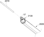
- the electronic pen 2000 includes a main body 2020 for fixing a core portion 2010 (see FIG. 42) to enable writing in a medium 1000, and the core portion 2010 in an unused state. ) May include a cap portion 2030.
- the non-use state may refer to a state in which the electronic pen 2000 is stored according to an embodiment of the present invention.
- the core part 2010 is not exposed to the outside and thus writing is impossible in the medium. It may mean.
- the core part 2010 may be a component capable of writing in the medium 1000, and may include balls and inks, and the inks may be oily, aqueous, or neutral.
- the core portion 2010 may be a black core used for a pencil or a core used for a general writing instrument.
- the main body 2020 is a component that can be inserted to expose a portion of the core portion 2010 to fix the core portion 2010 and may mean a kind of grip portion that can be gripped by a user by hand.
- Cap portion 2030 may have a predetermined internal space that can be inserted into one side of the body portion 2020 in a non-use state to protect the core portion 2010, inserted into the other side of the body portion 2020 If so, a portion of the core part 2010 may be exposed to the outside to enable writing.
- the cap part 2030 when the cap part 2030 allows writing by the core part 2010, the cap part 2030 does not necessarily need to be inserted into the other side of the main body part 2020, and is separated from the main body part 2020 by a predetermined space. It may be arranged in.
- the electronic pen 2000 includes an input unit 2100, an output unit 2200, a pattern detection unit 2300, a communication unit 2400, a sensor unit 2500,
- the memory 2600 may include a power supply 2700, a controller 2800, and the like.
- the components shown in FIG. 4 are not essential, an electronic pen having more components than the illustrated components or fewer components than the illustrated components may be implemented.
- the input unit 2100 may receive a user input from a user.
- the user input may be in various forms, including button input, key input, touch input, and voice lunar calendar.
- the electronic pen 2000 may control a power on / off of the electronic pen 2000 by receiving a button input from a user.
- Examples of the input unit 2100 include a button, a jog wheel, and the like, as well as a touch sensor that senses a user's touch, a microphone that receives a voice signal, a camera that recognizes a gesture through image recognition, and a user's approach.
- a comprehensive sensor that includes a proximity sensor composed of an illuminance sensor, an infrared sensor, etc., a motion sensor that recognizes a user's motion through an acceleration sensor, a gyro sensor, and the like, and various other input means for detecting or receiving various types of user input.
- the output unit 2200 may output various types of information and provide the same to the user.
- the output unit 2200 is a display for outputting visible light that can be recognized through the user's vision, a speaker for outputting the sound that can be recognized through the user's hearing, generating a vibration that can be recognized through the user's tactile sense It should be interpreted as a comprehensive concept that includes both haptic devices and various other forms of output means.
- the electronic pen 2000 may include a buzzer provided in the electronic pen 2000 to provide a user with information about whether the electronic pen 2000 is turned on or off, or whether the electronic pen 2000 is switched off. sound of a predetermined characteristic through a buzzer).
- predetermined visible light may be output through a display such as an LED lamp.
- the pattern detecting unit 2300 is configured to detect a code pattern in which position information for determining the position of the electronic pen 2000 with respect to the medium 1000 is encoded, and includes a camera module 2320 and a lighting module ( 2340).
- the camera module 2320 is for acquiring an image of a code pattern provided to the medium 1000.
- the camera module 2320 is adapted to a predetermined time interval (for example, 1/60 second to 1/240 second, etc.) while the electronic pen 2000 moves on the medium 1000 according to a user's writing or the like. Acquire an image of a partial region of the code pattern provided to the medium 1000. Accordingly, the electronic pen 1000 analyzes the information about the unit cell included in the acquired image according to the method of interpreting the code pattern described later, and then positions the electronic pen 2000 with respect to the medium 1000. Can be interpreted in the form of coordinates.
- the lighting module 2340 irradiates the medium 1000 with light of a predetermined specific frequency so that an image of a code pattern may be obtained through the camera module 2320.
- the code pattern provided to the medium 1000 according to the embodiment of the present invention may be printed using an ink that absorbs infrared rays. In this case, the lighting module 2340 may be well absorbed by the ink. Light of a wavelength may be irradiated to the medium 1000.
- the camera module 2320 may be configured to capture an image of the infrared band, for this purpose, the camera module 2320 may be provided with an infrared filter for selectively passing only the infrared band.
- the communication unit 2400 may perform communication with an external device.
- the electronic pen 2000 may communicate with the electronic device 3000 or the server 4000 through the communication unit 2400. Accordingly, the electronic pen 2000 may transmit and receive various information with the external device.
- the electronic pen 2000 may transmit pen data generated by the electronic pen 2000 to the electronic device 3000 or the server 4000 through the communication unit 2400, and the electronic pen 2000.
- Command and / or data for controlling an operation or providing information necessary for the electronic pen 2000 may be received from the electronic device 3000 or the server 4000 through the communication unit 2400. .
- the communication unit 2400 may include a wired module 2420 and a wireless module 2440.
- the wired module 2420 is a module for wired transmission / reception of data with an external device, and may include a configuration such as a USB port, a PS / 2 port, a parallel port, a serial port, and the like for transmitting and receiving data with an external device.
- the network may include an Ethernet port for connecting to the Internet through a local area network (LAN).
- LAN local area network
- the wireless module 2440 is a mobile communication module that connects to a mobile communication network via a mobile communication base station and transmits and receives data, a wireless local area network (WLAN) -based communication method such as Wi-Fi, Bluetooth, It may include a short range communication module using a communication method of a wireless personal area network (WPAN) series such as Zigbee.
- WLAN wireless local area network
- WPAN wireless personal area network
- the sensor unit 2500 may sense various information.
- the various information may be used to generate a control signal for controlling the operation of the electronic pen 2000 and may be used to generate pen data generated by the electronic pen 2000.
- Various information sensed through the sensor unit 2500 may be provided to the electronic device 3000 or the server 4000.
- the sensor unit 2500 may include a pressure sensor 2520, a pen core sensor 2540, a slip sensor 2560, and the like.
- the pressure sensor 2520 may sense the pressure generated when the user writes. For example, when the user writes using the electronic pen 2000, the contact of the electronic pen 2000 with respect to the writing surface occurs, and the pressure generated at this time is sensed by the pressure sensor 2520. Can be. In particular, the pressure sensor 2520 may be provided at the rear end (the other end of the pen tip other than the pen tip of the pen nib) mounted on the electronic pen 2000 to sense pressure. The electronic pen 2000 may use the pressure value sensed by the pressure sensor 2520 to generate pen data, which will be described later in detail. In this case, the pressure value included in the pen data may be processed into pen pressure information applied to the medium 1000 when the user writes, and may be used to reproduce the content written by the user. Alternatively, the electronic pen 2000 in the off state may be used as a trigger signal for turning on the state of the electronic pen 2000 based on the signal output through the pressure sensor 2520.
- the pen core sensor 2540 may detect a nib identifier for indicating the type of the nib (core portion) 2010 mounted on the electronic pen 2000.
- a nib identifier for indicating the color of the nib (core) 2010 may be provided on an outer side of the nib (core) 2010 mounted on the electronic pen 2000.
- the nib sensor 2540 is provided.
- the pen nib identifier may be detected through an optical method, a magnetic method, or various other available methods.
- Information about the pen core (core) 2010 interpreted by the value sensed by the pen core sensor 2540 or the sensed value may be provided to the electronic device 3000, and the electronic device 3000 may provide the received information. It can be used to reproduce the content written by the user based on.
- the slip sensor 2560 may detect a state of the electronic pen 2000 used to determine whether the electronic pen 2000 in the on state is automatically switched to the off state.
- the slip sensor 2560 may include an acceleration sensor and the like, and the movement of the electronic pen 2000 may be sensed through the acceleration sensor. If it is determined that the electronic pen 2000 is not moving for a predetermined time based on the value sensed by the slip sensor 2560, the electronic pen 2000 automatically turns off the electronic pen 2000. The state can be turned off.
- the electronic pen 2000 when the electronic pen 2000 is in an on state, power is normally supplied to the components provided in the electronic pen 2000 so that the components operate normally as necessary.
- the electronic pen 2000 when the electronic pen 2000 is in an off state, power to all or some of the components of the electronic pen 2000 is cut off and provided to the electronic pen 2000. Some or all of the components may not work properly.
- an analysis module for analyzing a signal output from the pressure sensor 2520 and / or the pressure sensor is normally used. Power may be supplied, whereby the electronic pen 2000 in the off state may be automatically turned on based on the sensing value output from the pressure sensor 2520.
- the memory 2600 may store various kinds of information.
- the memory 2600 may store data temporarily or semi-permanently.
- An operation program such as firmware for driving the electronic pen 2000 may be stored in the memory 2600. If necessary, the pen data and sensor unit 2500 generated by the electronic pen 2000 may be stored. Information, commands, and data necessary for driving the electronic pen 2000 such as a sensing value output by the electronic pen 2000 may be stored.
- Examples of the memory 2600 include a hard disk drive (HDD), a solid state drive (SSD), a flash memory, a read-only memory (ROM), a random access memory (RAM), and the like. This can be.
- HDD hard disk drive
- SSD solid state drive
- flash memory a read-only memory
- RAM random access memory
- the power supply unit 2700 may provide power for operation of each component of the electronic pen 2000.
- the power supply unit 2700 may be implemented as a rechargeable battery.
- the communication unit 2400 of the electronic pen 2000 includes a charging port (for example, a USB port)
- the electronic pen through the charging port
- the battery may be charged.
- the controller 2800 controls overall operations of the electronic pen 2000. To this end, the controller 2800 may calculate and process a variety of information and control the operation of the components of the electronic pen 2000.
- controller 2800 may analyze the image of the code pattern acquired by the pattern detection unit 2300 and decode information encoded in the unit cell included in the image of the obtained code pattern. Furthermore, the position coordinates of the medium 1000 of the electronic pen 2000 and the identification information (for example, book information or page information) of the medium 1000 may be obtained from the decoded information.
- the controller 2800 may generate pen data based on information obtained by decoding information encoded in a unit cell. As described above, the generated pen data is stored in the memory 2600 or the The electronic device 3000 may be transmitted to the electronic device 3000 and / or the server 4000 through the communication unit 2400. A detailed description of the generation of the pen data will be given later.
- the controller 2800 analyzes an image acquired by the first controller and the pattern detector 2300 for controlling a general operation of the electronic pen 2000, decodes information required for a unit cell,
- the controller 2800 may be logically divided into the first controller and the second controller, but the first controller and the second controller are physically divided. It may be implemented in a form that is separated from each other.
- the controller 2800 may be implemented as a computer or a similar device according to hardware software or a combination thereof.
- the controller in the form of hardware may be provided in the form of an electronic circuit that processes an electrical signal to perform a control function, and may be provided in the form of a program for driving the controller in form of hardware.
- the operation of the electronic pen 2000 may be interpreted to be performed by the control of the controller 2800.
- FIG. 5 is a block diagram illustrating components of an electronic device according to embodiments of the present disclosure.
- the electronic device 3000 may include an input module 3100, an output module 3200, a communication module 3300, a memory module 3400, and a control module 3500.
- the components illustrated in FIG. 5 are not essential, an electronic device having more components than the illustrated components or fewer components than the illustrated components may be implemented.
- the input module 3100 may receive a user input from a user.
- the user input may be in various forms, including key input, touch input, and voice lunar calendar.
- Examples of the input module 3100 capable of receiving user input include a conventional keypad, keyboard, and mouse as well as a touch sensor for detecting a user's touch, a microphone for receiving a voice signal, and a gesture recognition through image recognition. Cameras, proximity sensors, which consist of illuminance sensors or infrared sensors that detect user access, motion sensors that recognize user movements through acceleration sensors, gyro sensors, etc. A comprehensive concept that includes all of the input means.
- the touch sensor may be implemented as a piezoelectric or capacitive touch sensor that senses a touch through a touch panel or a touch film attached to the display panel, an optical touch sensor that senses a touch by an optical method, and the like.
- the output module 3200 may output various types of information and provide the same to the user.
- the output module 3200 may include a display for outputting visible light that can be recognized through the user's vision, a speaker for outputting sound that can be recognized through the user's hearing, and a vibration that can be recognized through the user's tactile sense. It is a comprehensive concept that includes both haptic devices and various other forms of output means.
- the display may output an image for reproducing contents written by a user using the electronic pen 2000 and / or the electronic apparatus 3000 according to an embodiment of the present invention.
- the display is a liquid crystal display (LCD),
- LED Light emitting diode
- OLED organic light emitting diode
- FPD flat panel displays
- transparent displays curved displays
- flexible displays concept of a broad image display device including a flexible display, a 3D display, a holographic display, a projector, and various types of devices capable of performing image output functions to be.
- a display may be in the form of a touch display integrated with a touch sensor of the input module 3100.
- the communication module 3300 may communicate with an external device.
- the electronic device 3000 may communicate with the electronic pen 2000 or the server 4000 through the communication module 3300. Accordingly, the electronic device 3000 may transmit and receive various information with the external device.
- the electronic device 3000 may receive pen data generated by the electronic pen 2000 through the communication module 3300 and transmit necessary information to the electronic pen 2000.
- the electronic device 3000 may transmit the pen data received from the electronic pen 2000 or the stroke data obtained by the analysis of the pen data to the server 4000 through the communication module 3300, and necessary information. Can be received from the server 4000.
- the communication module 3300 is a mobile communication via a wired communication module including a LAN port, a USB port, a PS / 2 port, a parallel port, a serial port, and the like, connected to the Internet through a local area network (LAN), and a mobile communication base station.
- Mobile communication module that connects to the network and transmits and receives data.
- WLAN Wireless Local Area Network
- Wi-Fi Wireless Local Area Network
- WPAN Wireless Personal Area Network series
- It may be configured as a short-range communication module using a communication method of, a satellite communication module using a global navigation satellite system (GNSS) such as a global positioning system (GPS), or a combination thereof.
- GNSS global navigation satellite system
- GPS global positioning system
- the memory module 3400 may store various types of information.
- the memory module 3400 may store data temporarily or semi-permanently.
- the memory module 3400 may store an operating program (OS; operating system) for driving the electronic device 3000, and if necessary, various data received from the electronic pen 2000 and the electronic pen 2000.
- An application for processing various data received from the application may be stored.
- Examples of the memory module 3400 include a hard disk drive (HDD), a solid state drive (SSD), a flash memory, a read-only memory (ROM), and a random access memory (RAM). And the like.
- HDD hard disk drive
- SSD solid state drive
- flash memory a read-only memory
- RAM random access memory
- the control module 3500 controls the overall operation of the electronic device 3000. To this end, the control module 3500 may perform calculation and processing of various information and control the operation of the components of the electronic device 3000.
- the control module 3500 may be implemented as a computer or a similar device according to hardware software or a combination thereof.
- the control module in hardware form may be provided in the form of an electronic circuit that processes an electrical signal to perform a control function, and may be provided in the form of a program for driving a control module in hardware form in software.
- the operation of the electronic device 3000 may be interpreted to be performed by the control of the control module 3500.
- a user may write to the medium 1000 according to some embodiments of the present invention using the electronic pen 2000 according to the embodiments of the present invention.
- the electronic pen 2000 acquires an image of at least a portion of the code pattern included in the medium 1000 according to some embodiments of the present invention, and obtains the image.
- Location information may be obtained by analyzing information encoded in a unit cell included therein.
- the electronic pen 2000 continuously acquires and processes / stores an image of a code pattern and position information interpreted therefrom while the user is writing, so that the user may later change the image on the medium 1000.
- Basic data that can be interpreted whether or not writing has been performed along the trajectory can be generated.
- the electronic pen 2000 since the electronic pen 2000 according to the embodiments of the present invention uses a commonly used pen nib (core part) 2010, the writer is only required for the medium 1000 according to some embodiments of the present invention. It is not possible and writing on a general medium (for example, paper without a code pattern) is possible. However, in such a case, since the electronic pen 2000 cannot obtain position information for analyzing the user's writing trajectory, the electronic pen 2000 may perform an operation such as real time reproduction and replay of the user's writing trajectory as described later. 3000) and so on.
- the code pattern according to an embodiment of the present invention is configured in such a way that one unit cell is repeatedly arranged to a desired size in two dimensions.
- 6 and 7 are diagrams exemplarily illustrating a unit cell constituting a code pattern according to an embodiment of the present invention.
- each unit cell includes codes in the form of line segments, and codes in the line segment form can be largely classified into a reference code and an information code.
- the reference code consists of horizontal reference code, vertical reference code and cross-reference code.
- the reference code has a function of confirming an area of a unit cell when decoding a code pattern.
- the information code performs a function for indicating information to be encoded in the unit cell in a manner described later.
- the reference codes and the information codes except the cross-reference code have the same geometric shape. That is, the reference codes and the information codes except the cross-reference code have a rotationally symmetrical shape, and are 'line segments'.
- Cross-reference codes unlike other reference codes and information codes, have a cross-shaped geometry.
- virtual lines may be defined, wherein the virtual lines are composed of a plurality of horizontal virtual lines extending in the horizontal direction and a plurality of vertical virtual lines extending in the vertical direction.
- a component called 'virtual line' may or may not be actually printed on the medium 1000.
- Each of the plurality of horizontal virtual lines may be parallel to each other and spaced apart from each other by a predetermined interval.
- each of the plurality of vertical virtual lines is parallel to each other, and are disposed apart from each other by a predetermined interval.
- the horizontal virtual line of any one of the plurality of horizontal virtual lines is orthogonal to each other with the vertical virtual line of any one of the plurality of vertical virtual lines.
- a plurality of intersections are formed in which a plurality of horizontal virtual lines and a plurality of vertical virtual lines meet and form each other, and the plurality of intersections are hereinafter referred to as virtual reference points.
- a component called 'virtual point' may or may not be actually printed on the medium 1000.
- one unit cell is illustrated as having a total of seven horizontal virtual lines and seven vertical virtual lines, and the horizontal reference codes are arranged on the horizontal virtual line disposed on the top thereof. It is shown that the vertical reference codes are arranged in the vertical virtual line which is arranged on the far left.
- the reference codes are placed on the virtual reference point.
- the reference codes are arranged such that the center of mass is at the virtual reference point. That is, the horizontal reference codes and the vertical reference codes are arranged so that the virtual reference point can be located at the center of both ends of the respective reference codes.
- the cross reference code having a cross shape is arranged so that the center of the cross is at the virtual reference point.
- Information codes are also placed on the virtual reference point.
- the information codes unlike the reference codes, are arranged so that their center of mass is not placed at the virtual reference point. That is, the virtual reference point is not disposed at the center of both ends of the information codes.
- one end of both ends is placed near the virtual reference point and the other end is determined according to the value to be encoded in the information code. It is placed at a location, different from the virtual reference point. This will be described in detail in the method of encoding information in the information codes.
- the code pattern having the shapes and components as described above is formed in the medium 1000, and the code pattern is actually formed in the medium 1000, which may be implemented by printing or the like.
- the code pattern is printed on the medium 1000, only the above-described reference code and information code may be printed as shown in FIG. 7. That is, the horizontal virtual lines, the vertical virtual lines, and the virtual reference points among the components constituting the code pattern may not be actually printed.
- the basic principle of encoding information in an information code is to place one end of the information code in the vicinity of the virtual reference point and the other end of the information code so that the information code passes through the virtual reference point, from the one end to the other.
- the desired information is encoded in the corresponding information code.
- the direction of the information code from one end of the information code (the end disposed closer to the virtual reference point) to the other end (the end disposed farther than the virtual gimmick point) (hereinafter referred to as the direction of the information code).
- the desired information is encoded.
- FIG. 8 is a diagram illustrating a method of encoding 2 bits of information into an information code according to embodiments of the present invention.
- a hypothetical reference point at which the information code to be encoded is to be placed is the origin, and a rectangular coordinate system defined in the direction of the horizontal reference codes and the vertical reference codes provided in the unit cell is assumed.
- one end of the information code (end closer to the virtual reference point) is in the three quadrants of the Cartesian coordinate system and the other end (the The farther end of the virtual reference point) may determine the direction of the information code to be located in the first quadrant of the rectangular coordinate system (see FIG. 8A).
- one end of the information code (end closer to the virtual reference point) is in the quadrant of the rectangular coordinate system and the other end (the virtual reference point). A farther end with respect to) may determine the direction of the information code so that it can be located in two quadrants of the Cartesian coordinate system (see FIG. 8B).
- one end of the information code (end closer to the virtual reference point) is in one quadrant of the Cartesian coordinate system and the other end (the The farther end with respect to the virtual reference point) may determine the direction of the information code so that it can be located in the three quadrants of the rectangular coordinate system (see (c) of FIG. 8).
- one end of the information code (end closer to the virtual reference point) is in the two quadrants of the Cartesian coordinate system and the other end (the The farther end with respect to the virtual reference point) may determine the direction of the information code to be located in the quadrant of the Cartesian coordinate system (see (d) of FIG. 8).
- the other end of the information code from one end of the information code (for example, the end located closer to the virtual reference point)
- the number of bits of information that can be encoded in the information code is not limited to 2 bits, and may be 3 bits or more.
- the direction of the information code is interpreted in units of 45 degrees in order to encode the information into the information code, the information code has a total of 8 distinct directions, and thus, a total of 3 bits of information is stored in one information code. You can encode it.
- the unit cell information encoded in the unit cell may include error verification information, medium identification information, coordinate information, and other additional information.
- the error verification information is information for determining whether an error has occurred during encoding of the unit cell.
- the medium identification information is identification information about the medium 1000 to which the unit cell is provided.
- the medium identification information may include book information, page information, and the like.
- the book information means identification information given to the notebook or book when the plurality of mediums 1000 are manufactured in the form of the notebook or the book.
- the page information may be used to identify on which page the medium 1000 provided with the unit cell is located in the note or book. Means information.
- the medium identification information may be determined by the medium 1000. It may contain information to identify what format it has.
- the coordinate information refers to two-dimensional coordinate information indicating which unit cell is located on the medium 1000 where the unit cell is provided. Accordingly, the coordinate information may include x coordinates and y coordinates.
- the other additional information may include other various necessary information.
- license information about a coordinate code provided to the medium 1000 may be included in the other additional information.
- the electronic pen 2000 analyzes at least one unit cell included in the image acquired through the pattern detecting unit 2300 and decodes the information encoded in the corresponding unit cell.
- the cell information may be obtained, and accordingly, medium identification information, coordinate information, and other additional information included in the unit cell information may be obtained.
- the pen data refers to information used to generate stroke data necessary for reproducing a user's writing trajectory in real time or replaying it later in addition to the unit cell information obtained by the electronic pen 2000.
- the pen data may include visual information, pen pressure information, position information, medium identification information, and the like.
- the visual information is information about a time point at which an image used to generate one unit pen data is acquired, or a time point at which one unit pen data is generated.
- the pen pressure information is pressure information output from the pressure sensor 2520 at the time when an image used to generate one unit pen data is acquired or when one unit pen data is generated.
- the medium identification information is the same as or similar to the information included in the unit cell information, detailed description thereof will be omitted.
- the position information is information about the position of the electronic pen 2000 with respect to the medium 1000 generated by performing a correction operation necessary for the coordinate information obtained from the unit cell information.
- the location information may coincide with or not coincide with coordinate information obtained from unit cell information. A method of generating location information will be described in detail below.
- FIG. 9 is a diagram for describing a method of generating location information of an electronic pen with respect to a medium according to embodiments of the present disclosure.
- an image I acquired by the camera module 2320 of the electronic pen 2000 is exemplarily illustrated.
- the unit cell UC may be included, and the position CC of the unit cell UC may be obtained in the form of coordinates by analyzing the information encoded in the unit cell by the above-described method.
- the unit cell UC used to interpret the coordinate information may not be located at the center of the acquired image I, it is obtained by the analysis of the unit cell UC.
- the coordinate information may be slightly different from the exact position of the electronic pen 2000 with respect to the medium 1000. That is, it can be assumed that the center IC of the acquired image I is closest to the position of the electronic pen 2000 with respect to the medium 1000.
- the center IC of the acquired image I is the unit cell. It may be different from the coordinates (x, y) obtained by the coordinate information obtained from (UC).
- the electronic pen 2000 obtains the coordinate information obtained from the unit cell UC and the acquired image in order to obtain the coordinates (x ', y') of the center (IC) of the acquired image (I).
- the offset value (offset) between the center (IC) of I) is calculated, and the offset value (? X,? Y) calculated by adding or subtracting the calculated offset value (x, y) from the unit cell UC is obtained.
- the coordinates (x ', y') of the center (IC) of the image (I) is calculated.
- the position of the electronic pen 2000 with respect to the medium 1000 may be more accurately calculated, and the coordinate information (x ', y') corrected in the above manner may be the aforementioned position information. to be.
- the electronic pen 2000 may continuously generate pen data, and accordingly, the movement of the position of the electronic pen 2000 with respect to the medium 1000 according to the user's writing is performed in real time in the form of pen data.
- the pen data may be properly processed by the electronic device 3000 or the server 4000 as necessary later.
- the electronic pen 2000 may store the pen data in the memory 2600 or transmit the pen data to the electronic device 3000 through the communication unit 2400.
- the electronic pen 2000 when the electronic pen 2000 is in a state capable of communicating with the electronic device 3000, the electronic pen 2000 may generate pen data and directly transmit the pen data to the electronic device 3000 in real time.
- the electronic pen 2000 When the electronic pen 2000 is not in a state capable of communicating with the electronic device 3000, the electronic pen 2000 generates pen data and stores the pen data in the memory 2600, and later communicates with the electronic device 3000.
- the pen data stored in the electronic device 3000 can be transmitted.
- the electronic device 3000 may reproduce in real time what the user writes on the medium 1000 based on the pen data received from the electronic pen 2000, and display the content on the display of the electronic device 3000.
- a description will be given of a method of reproducing in real time what the user has written and displaying it on the display.
- the electronic device 3000 may acquire information about the target medium 1000 that the user is writing based on the medium identification information included in the pen data received from the electronic pen 2000.
- the electronic device 3000 may be a medium in which a user's writing medium 1000 is a medium having a specific format for a particular use or a part of a product provided in a book or a notebook form. Check whether or not.
- the target medium 1000 is a medium that forms part of a product provided in a book or notebook form, it may be determined whether the target medium 1000 is a medium located on some pages of the book or note. have.
- the electronic device 3000 may display, on the display, a template previously stored for the target medium 1000 or writing contents already written by the user for the target medium 1000 based on the obtained medium identification information. Can be.
- the template for the target medium 1000 previously stored means that the target medium 1000 includes text, an image, a shape, a symbol, and the like already printed in addition to the code pattern.
- a plurality of lines may be printed on the target medium 1000 for easy writing by the user, such that the plurality of lines are printed. It may be included in template information about the target medium 1000 previously stored.
- the target medium 1000 may be printed with a specific date such as February 1, 2015. Special information is printed at 1000 may also be included in the predetermined template information.
- the image displayed for the target medium 1000 including the template information described above may be referred to as a medium image.
- the electronic device 3000 may generate stroke data corresponding to the trajectory of the user's writing to be displayed on the display, based on the positional information and the time information included in the received pen data.
- the electronic device 3000 may generate stroke data corresponding to the trajectory of the user's writing to be displayed on the display, based on the positional information and the time information included in the received pen data.
- at least one or more unit pen data may be used.
- the electronic device 3000 may reproduce the trajectory written by the user with respect to the target medium 1000 according to the generated stroke data as it is at a corresponding position on the predetermined template displayed on the display.
- FIG. 10 illustrates that the contents written by the user in the target medium 1000b are reproduced on the display of the electronic device 3000 in real time.
- the trajectory of the user's handwriting content, the position of the user's handwriting content on the target medium 1000, and the like are located in the pen data information. Based on this, it can be accurately reproduced.
- 11 to 15 are views for explaining another embodiment of reproducing in real time the user's handwriting content according to the present invention.
- the user may use the entire surface of the target medium 1000 to which the user is currently writing the electronic device 3000. Although it may be desired to be displayed through, in some cases, only a part of surface of the target medium 1000 may be desired to be displayed through the electronic device 3000.
- the term 'partial area (or display area) of the target medium' is displayed ' may mean that the area corresponding to the partial area of the target medium is displayed on the display among the entire area of the medium image.
- FIG. 11 only a portion of the target medium 1000 is displayed through the electronic device 3000.
- the electronic device 3000 continues through some areas set as shown in FIG. 11. If it is displayed, the content corresponding to 'E' that the user additionally writes cannot be viewed through the electronic device 3000.
- Another embodiment of reproducing the user's handwriting content in real time according to the present invention is proposed to solve the problem.
- the electronic device 3000 may identify a position (hereinafter, referred to as “writing position”) in the target medium 1000 of the content currently being written by the user based on the received pen data.
- the electronic device 3000 may determine whether the checked writing position satisfies a predetermined condition for the current display area.
- the electronic device 3000 may determine whether the writing position corresponds to a position outside the display area. In this case, when the electronic device 3000 determines that the writing position is in a position outside the display area, the electronic device 3000 may determine that the predetermined condition is satisfied.
- the electronic device 3000 may determine whether the checked writing position corresponds to an edge area of the current display area. That is, the electronic device 3000 may determine whether the writing position corresponds to an edge area of the display area even though the writing position is currently included in the display area. In this case, when it is determined that the writing position corresponds to an edge area of the display area, the electronic device 3000 may determine that the predetermined condition is satisfied.
- the electronic device 3000 determines that the writing position does not satisfy a predetermined condition (for example, when it is determined that the writing position is included in the display area).
- the electronic device 3000 is illustrated in FIG. 12.
- 'E' corresponding to the content written by the user may be reproduced through the electronic device 3000 and displayed on the display without shifting the display area.
- the electronic device 3000 determines that the writing position satisfies a predetermined condition (for example, when it is determined that the writing position is out of the display area), the electronic device 3000 corresponds to the writing position.
- the position of the display area may be shifted so that the position may be displayed on the display of the electronic device 3000.
- the electronic device 3000 shifts the display area as shown in FIG. 13, Content corresponding to the user's handwriting can be reproduced in the shifted display area.
- the electronic device 3000 may determine a direction in which the position of the display area is shifted in consideration of the writing direction of the contents described by the user.
- FIG. 13 illustrates that the position of the display area is shifted in the same direction as the writing direction of 'ABCDE', which is contents written by the user.
- the electronic device 3000 may shift the position of the display area such that the content of the written handwriting out of the original display area is displayed at the center portion of the shifted display area.
- FIG. 14 illustrates that the display area is shifted so that the 'F' described above the position of the original display area may be positioned at the center portion of the shifted display area.
- the electronic device 3000 may shift the position of the display area in consideration of a distance and a direction between the content that was written immediately before and the content of the written content that deviates from the original display area.
- the electronic device 3000 may consider an edge of the media image when shifting the position of the display area. For example, the position of the display area may be shifted so that the edge of the media image does not deviate from the predetermined area of the display screen. That is, the position of the display area may be shifted so that the edge of the media image does not leave the edge area of the display screen. In other words, the position of the display area may be shifted so that the edge of the preview image is not displayed spaced apart from the edge area of the display screen by more than a predetermined distance.
- the electronic device 3000 considers pen data received from the electronic pen 2000 to determine whether the writing position satisfies a predetermined condition, and the electronic device 3000 checks the writing position.
- Various methods may be applied to a method of sampling pen data.
- the electronic device 3000 determines whether the writing position satisfies a predetermined condition for the partial region with respect to all the unit pen data (for example, whether the writing position is outside the display region). can do.
- the electronic device 3000 may reproduce the user's handwriting through the electronic device 3000 close to the real time reproduction, but there may be a problem in that the amount of calculation increases.
- the electronic device 3000 may determine whether a writing position satisfies a predetermined condition for the display area with respect to at least some of the pen data that may be bundled in a stroke unit.
- the stroke refers to a line drawn on the writing surface by the pen until the pen comes off the writing surface after the pen contacts the writing surface, and may be referred to as a 'stroke'. That is, 'A' is generally composed of three strokes, 'B' is generally composed of two strokes, 'C' is generally one stroke, and 'D' is generally two strokes. 'E' generally consists of three strokes.
- 'pen down' an operation in which the user contacts the electronic pen 2000 to the target medium 1000 is referred to as 'pen down', and one stroke is written. Afterwards, an operation in which the user detaches the electronic pen 2000 from the target medium 1000 will be referred to as 'pen up'.
- the electronic pen 2000 includes the pen pressure sensed through the pressure sensor in the pen data, and generates the pen data, and the generated pen data is transmitted to the electronic device 3000, so that the electronic device 3000 includes a pen.
- the pen pressure value included in the data may be used to determine whether the pen is down or the pen is up. That is, when the pen pressure value suddenly rises from '0' to a specific value during the reception of the pen data, the electronic device 3000 may determine that the 'pen down' occurs when the pen pressure value suddenly rises. For convenience, this point will be defined as a 'pen down point'. In addition, when the pen pressure value suddenly becomes “0” during the reception of the pen data, the electronic device 3000 may determine that the “pen up” occurs when the pen pressure value suddenly becomes “0”. For convenience, this point will be defined as a 'pen up point'.
- the electronic device 3000 may determine whether the writing position satisfies a predetermined condition for the display area by using position information included in the pen data corresponding to the pen down time point among the pen data bundled in the stroke unit. (Hereinafter, pen down based shift method). In this case, the electronic device 3000 uses only the writing position at the time of pen down and the position information included in the remaining pen data among the plurality of pen data groups grouped by the stroke unit may be written in advance in the display area. It may not be used in determining whether a predetermined condition is satisfied.
- the electronic device 3000 may determine whether the writing position satisfies a predetermined condition for the display area by using position information included in the pen data corresponding to the pen-up time point among the pen data bundled in the stroke unit. Can be determined (hereinafter, a pen-up based shift method). In this case, the electronic device 3000 uses only the writing position at the time of pen-up and the position information included in the remaining pen data among the plurality of pen data groups grouped by the stroke unit may be written in advance in the display area. It may not be used in determining whether a predetermined condition is satisfied.
- the electronic device 3000 may be configured to determine a writing position of the display area using all of the position information included in the pen data corresponding to the pen up time and the pen down time, among the pen data bundled in a stroke unit. It can be determined whether the condition is satisfied (hereinafter, referred to as a hybrid shift method). In this case, the electronic device 3000 may use only the writing positions at the pen down time and the pen up time, and do not use the remaining pen data.
- the shift of the display area occurs only at the pen down time point, the time point of the stroke input by the user is included in the original display area. If it is out of the display area of, the shift according to the present invention may not occur. That is, as shown in Fig. 15, even after the user completes the stroke S, the start point SP of the stroke S is included in the original display area, so that the end point of the stroke S ( Even if EP is outside the original display area, the screen as shown in FIG. 15B may be shown through the display of the electronic device 3000 even at the pen-up time Tup.
- the electronic device 3000 may not perform the shift operation until the user's stroke input is completed.
- the advantages of the pen down based shift method and the pen down based shift method may be taken.
- the pen data and the pen up time at the time of pen down as described above.
- the determination of the writing position using the pen data selected according to a predetermined time interval may be performed. There may be a way to do this. That is, pen data at the pen down time, pen data at the 0.05 second pass from the pen down point, pen data at the 0.10 second pass from the pen down point, and pen data at the 0.15 second pass down from the pen down point are recorded. There may be a method for making a determination on (if the predetermined time interval is 0.05 seconds).
- the electronic device 3000 may determine whether there is at least one shift operation with respect to one stroke. That is, for each stroke, the electronic device 3000 may determine whether the predetermined condition is satisfied using at least one pen data among the plurality of pen data included in the stroke.
- the electronic device 3000 may include pen data (first pen data) corresponding to a pen down time constituting one stroke, pen data (second pen data) and first pen data corresponding to a pen up time. It is possible to determine whether the predetermined condition is satisfied using at least one pen data among all pen data between the second pen data and the second pen data.
- the screen of the electronic device 3000 is enlarged so that only the display area of the target medium 1000 is enlarged. Even when displayed through the display, the user's handwriting can be reproduced in real time to be displayed on the display of the electronic device 3000.
- a mode in which only a partial region of the target medium 1000 is displayed through the electronic device 3000 may be referred to as an enlarged mode, and the entire region of the target medium 1000 may be referred to. All of these modes displayed through the electronic device 3000 may be referred to as a 'normal mode'.
- the electronic device 3000 may operate in the above-described general reproduction mode or may operate in the enlarged reproduction mode in order to reproduce the user's handwriting contents in real time according to the present invention.
- the electronic device 3000 determines whether the display mode of the current electronic device 3000 is the 'normal mode' or the 'enlarge mode', and according to the determination result, reproduces the user's writing in real time. It can be operated by selecting a mode. That is, when the display mode of the electronic device 3000 is the “normal mode,” the electronic device 3000 reproduces the user's handwriting content in real time according to the aforementioned “normal reproduction mode” and the electronic device 3000.
- the display mode of the 'expanded mode' the user's handwriting can be reproduced in real time according to the above-mentioned 'expanded reproduction mode'.
- the reproduction mode when the reproduction mode is selectively set and operated, the 'expanded reproduction mode', which is relatively more computational, is applied only when the screen is enlarged and displayed, and when the screen is not enlarged and displayed, the relative As a result, the operation amount can be operated in a 'normal reproduction mode' having a smaller amount of computation, and thus, the user's handwriting contents can be reproduced in real time more effectively and efficiently.
- the electronic device 3000 may later replay the contents that the user writes in the medium 1000 based on the pen data received from the electronic pen 2000, and display the content on the display of the electronic device 3000.
- a description will be given of a method of replaying and displaying, on a display, the items being written by a user in real time.
- the electronic pen 2000 and the electronic device 3000 receive and store pen data about a matter written by the user in the target medium 1000 using the electronic pen 2000. do.
- the electronic device 3000 may detect whether a predetermined event for replaying the writing content of the user has occurred.
- the predetermined event may be a request of a user. That is, the electronic device 3000 may provide a user interface (UI) through which the user may request a replay of the writing content through the electronic device 3000, and the user may write through the user interface.
- the electronic device 3000 may request a replay of content, and accordingly, determine that a predetermined event has occurred, and perform a replay operation of the handwritten content according to the present invention.
- UI user interface
- the predetermined event may be a request of an operating system (OS) of the electronic device 3000 or another application installed in the electronic device 3000.
- OS operating system
- the predetermined event may correspond to a predetermined condition. That is, when a predetermined condition of 'reach to a specific time' is set, the electronic device 3000 monitors the current time, determines whether the 'predetermined time' of the predetermined condition is reached, and reaches the corresponding time. In this case, it may be determined that a predetermined event has occurred, and the replay operation for the user's handwriting according to the present invention may be performed.
- the predetermined condition is not limited to the condition for 'time' as described above, but may be set in various forms.
- the electronic device 3000 may determine target content for performing a replay operation on the written content.
- the electronic device 3000 may store all pen data about contents written by the user in the medium 1000 using the electronic pen 2000. Among the writing contents, the replay operation may be performed.
- the handwriting content to be performed may be determined. That is, if the target medium 1000 is provided in the form of a note, the electronic device 3000 writes all the contents written by the user on a plurality of pages of the note in the form of pen data (or stroke data). In this case, the electronic device 3000 may determine which page (one page or a plurality of pages) of a plurality of pages is to be replayed, or any specific page in the same page. It is possible to determine whether to perform a replay operation on the content written in the area.
- the electronic device 3000 may consider the predetermined event in determining the content of the replay.
- the replay target content may be determined according to the user's request.
- the predetermined event is a request of an operating system or another application
- the content to be replayed may be determined in consideration of the request.
- a replay target section may be determined. For example, when the electronic device 3000 determines a specific page of a note as a replay target section as content to be replayed, a plurality of strokes described in the determined specific page are determined as a replay target, and the plurality of replay target sections are included in the plurality of replay target sections. It is defined by the temporal relationship between the replay target strokes and the replay target strokes.
- the replay target section will be described in more detail.
- a replay section RS according to the present invention includes a stroke section SS and a gap section GS.
- FIG. 16 illustrates that the replay target section RS includes first to fourth stroke sections SS1, SS2, SS3, and SS4 and first to third sections GS1, GS2, and GS3. It is.
- the replay target section is defined as a time taken by the user to write the replay target.
- the replay target section is defined as the replay target section from the time when the user starts writing the first stroke of the target writing content requesting the replay to the time when the user finishes writing the last stroke of the target writing content. do.
- the replay target section RS is determined as shown in FIG. 16, the length of the replay target section RS is (t8-t1).
- the stroke section is defined as the time taken when a user inputs one stroke when writing. That is, as described above, the time from the time of pen down to the target medium 1000 to the time of pen up from the target medium 1000 to input one stroke is defined as a stroke section.
- the length of the first stroke section SS1 is (t2-t1)
- the length of the second stroke section SS2 is (t4-t3)
- the third stroke section is (t6-t5)
- the length of the fourth stroke section SS4 is (t8-t7).
- the interval section GS is defined as the time from when a user inputs one stroke to input another stroke immediately following the input stroke. That is, the time from the pen up time point of the stroke on which input is completed to the pen down time point of the next input stroke is defined as the interval section GS.
- the length of the first interval GS1 is (t3, t2)
- the length of the second interval GS2 is (t5-64)
- the third interval ( GS3) is (t7-t6) in length.
- interval section GS When defining an interval section GS, it is explained that it is defined by the relationship of two strokes, wherein two strokes for defining the interval section are defined by the relationship of the strokes included in the content of the replay target determined as the replay target.
- strokes not included in the replay subject matter are not considered. For example, one stroke (stroke A) is written to the first area (eg x pages of A note) and the next stroke (stroke B) is actually the second area (eg y note A). If the next stroke (stroke C) is listed again in the first area, then only page x is selected as the content to be replayed, and if page y is not selected, stroke B is included in the content to be replayed.
- the electronic device 3000 may obtain pen data about strokes included in the replay target content from the memory module 3400 and generate replay data based on the obtained pen data.
- the replay data is data generated to perform a replay operation of replaying the user's handwritten contents, and may be data generated by sampling pen data for strokes.
- the replay data may be interpreted in a very comprehensive sense including a position of a stroke for displaying on a display, a display order between strokes, timing information for displaying strokes, and the like in performing the replay operation.
- the electronic device 3000 then performs a replay operation according to the present invention based on the replay data.
- the replay time of the replay is different from the time taken by the user to write the replay target content.
- a specific page may be selected as the content to be replayed, and part of the content included in the specific page selected as the content to be replayed may be written at 10 am, and another part of the content included in the specific page May be written at 8:00 pm, in this case, the time required for the user to write the replayed content is 10 hours, but when the user replays the written content according to an embodiment of the present invention, playback of the replay is performed. Time can be minutes. That is, the replay playback time of the replay target section may be shorter than the writing duration of the replay target section (length of the replay target section).
- a particular word may be selected as the content to be replayed, and the time it takes for the user to actually enter the specific word selected as the content to be replayed is two seconds, but the replay time for the word is It may be a time of 2 seconds or more. That is, the replay playback time of the replay target section may be longer than the writing duration of the replay target section (length of the replay target section).
- the electronic device 3000 may determine the replay reproduction time of the strokes included in the content of the replay.
- the electronic device 3000 may determine the replay reproduction time for each stroke in consideration of the time taken for the strokes to be replayed to be actually written.
- FIG. 17 is a diagram showing a replay playback time determined according to an embodiment of the present invention for the replay target section RS as shown in FIG.
- the lengths of the first to fourth stroke replay replay times SR1, SR2, SR3, and SR4 for each of the first to fourth stroke sections SS1, SS2, SS3, and SS4 may be the first lengths, respectively.
- the one determined in proportion to the length of the first to fourth stroke sections SS1, SS2, SS3, and SS4 is illustrated.
- the electronic device 3000 may determine the replay reproduction time for the replay target strokes in consideration of the time taken for the replay target strokes to be actually written.
- the replay reproduction time is determined such that the replay reproduction time for each stroke is proportional to the length of each stroke period, but it is not necessarily determined proportionally.
- the time may be determined. For example, according to a method of dividing the time taken to actually write the respective strokes by section and corresponding different replay playback time to different sections, the replay playback time for each stroke is different. May be determined. That is, for the two strokes, even if the length of the actual stroke section is slightly different, when the two strokes are classified into the same section, the replay reproduction time for the two strokes can be determined to be the same.
- the replay playback time may be determined by further considering the length of. The method of considering the length of the stroke when determining the replay reproduction time will be described later.
- the electronic device 3000 may determine replay reproduction times that are the same with respect to the strokes to be replayed.
- the electronic device 3000 may determine the replay playback time for each stroke without considering the time taken for the strokes to be replayed to be actually written.
- the electronic device 3000 may determine the predetermined replay reproduction time as the replay reproduction time for each of the replay object strokes, regardless of the time taken to actually write the replay object strokes. That is, the replay playback time determined for all the strokes included in the replay target content may be the same.
- FIG. 18 and 19 are diagrams showing a replay reproduction time determined according to another embodiment of the present invention for the replay target section RS as shown in FIG.
- the lengths of the first to fourth stroke replay replay times SR1, SR2, SR3, and SR4 are the same for each of the first to fourth stroke sections SS1, SS2, SS3, and SS4. Is determined. As such, the electronic device 3000 may determine the replay reproduction time for the replay target strokes without considering the time taken for the replay target strokes to be actually written.
- the replay reproduction time is determined in the same manner without considering the length of the stroke section at all in determining the replay reproduction time for the respective strokes.
- the replay play time may be determined, and when the replay play time is determined in consideration of the length of the stroke, the replay play time for each stroke may be different. The method of considering the length of the stroke when determining the replay reproduction time will be described later.
- the determined replay playback time may be determined as one 'time point'.
- the electronic device 3000 may display the first at a first time point. Displays the strokes corresponding to the stroke section SS1 at once, displays the strokes corresponding to the second stroke section SS2 at the second time point, and displays the strokes corresponding to the third stroke section SS3 at the third time point. It is possible to display all at once and to display the strokes corresponding to the fourth stroke section SS4 at a time at the fourth time.
- the meaning of displaying the strokes at once may be understood to mean that all the points constituting the strokes are displayed on the display all at once at that time.
- FIG. 18 relates to an embodiment in which the points constituting each stroke are sequentially displayed on the display as the replay proceeds, and FIG. 19 illustrates that the points constituting the strokes are displayed on the display at once. It relates to an embodiment.
- the electronic device 3000 may determine the replay reproduction time for each stroke in consideration of the length of the strokes to be replayed.
- 20 to 24 are diagrams for describing some other embodiments of determining a replay play time for replaying a stroke written by a user according to some other embodiments of the present invention.
- the first to fourth strokes S1, S2, S3, and S4 are written in the target medium 1000.
- the first stroke S1 is written by the user during the first stroke period SS1 shown in FIG. 16, and the second stroke S2 is the second stroke period shown in FIG. 16. It is written by the user during SS2, the third stroke S3 is written by the user during the third stroke section SS3 shown in FIG. 16, and the fourth stroke S4 is shown in FIG. Assume that it is written by the user during the fourth stroke period SS4.
- each of the lengths of the first to fourth strokes S1, S2, S3, and S4 is called SL1, SL2, SL3, and SL4, and similarly to SL4> SL1. Assume that the relationship> SL3> SL2 holds.
- the length of the stroke may be understood to mean the physical length of the stroke actually written by the user in the target medium 1000. In this case, however, the length may be understood as an absolute length, but may be understood as a relative length between strokes.
- the electronic device 3000 may determine the replay reproduction time for each of the strokes in consideration of the lengths of the strokes included in the content of the replay.
- FIG. 21 illustrates the replay playback time determined according to some embodiments of the present invention with respect to the strokes S1, S2, S3, and S4 included in the replay target content as shown in FIG.
- the lengths of the first to fourth stroke replay reproduction times SR1, SR2, SR3, and SR4 for the first to fourth strokes S1, S2, S3, and S4 may be the first lengths, respectively. What is determined in proportion to the length of the fourth to fourth strokes S1, S2, S3, and S4 is shown. As such, the electronic device 3000 may determine the replay reproduction time for the replay target strokes in consideration of the time taken for the replay target strokes to be actually written.
- the replay reproduction time is determined such that the replay reproduction time for each stroke is proportional to the length of each stroke.
- the replay reproduction time is not necessarily determined proportionally. This may be determined.
- the replay reproduction time for each stroke may be determined according to a method in which the written lengths of the respective strokes are divided into sections and correspond to different replay reproduction times in different sections. That is, for the two strokes, if the two strokes are classified into the same section even though the written length of the actual stroke is slightly different, the replay reproduction time for the two strokes can be determined the same.
- the replay reproduction time may be determined by further considering the length of the stroke section (the time taken for the stroke to be actually written).
- the electronic device 3000 may determine, for the strokes to be replayed, the same replay play time with each other, regardless of the written length of the strokes. That is, the electronic device 3000 may determine the replay reproduction time for each stroke without considering the written length of the strokes to be replayed.
- 22 and 23 are diagrams showing the replay reproduction time determined according to some embodiments of the present invention, for the strokes to be replayed as shown in FIG.
- the lengths of the first to fourth stroke replay reproduction times SR1, SR2, SR3, and SR4 are the same for each of the first to fourth strokes S1, S2, S3, and S4. The decision is shown. As such, the electronic device 3000 may determine the replay reproduction time for the replay target strokes without considering the written length of the replay target strokes.
- the determined replay playback time may be determined as one 'time point'.
- the electronic device 3000 when replaying the strokes of the first to fourth strokes S1, S2, S3, and S4, the electronic device 3000 makes the first stroke at the first time point.
- Display the replays for (S1) at once display the replays for the second stroke (S2) at the second time at a time, display the replays for the third stroke (S3) at the third time at a time, and the fourth time
- the replay for the fourth stroke S4 can be displayed at once.
- the electronic device 3000 may determine the replay reproduction time of the interval between the strokes included in the content of the replay.
- the electronic device 3000 may determine the replay play time for each interval between the strokes, considering the actual time interval between the strokes. Can be.
- the method of determining the replay reproduction time for the intervals between is substantially the same as the method of determining the replay reproduction time for the stroke interval with or without considering the length of the stroke interval described above. Similar, only a brief description.
- the lengths of the first to third interval replay playing times GR1, GR2, and GR3 for the first to third intervals GS1, GS2, and GS3 may be the first to third, respectively. It is shown that it is determined in proportion to the length of the intervals between the three (GS1, GS2, GS3).
- the electronic device 3000 may determine the replay reproduction time for the section between the stroke and the stroke in consideration of the time difference between the stroke and the strokes generated while actually writing.
- the replay playback time determined for the interval section does not necessarily have to be proportionally determined for the length of the interval section.
- the electronic device 3000 may determine the same replay reproduction time with respect to sections between replay objects. For example, the electronic device 3000 may determine the replay playback time for each stroke without considering the time taken for the strokes to be replayed to be actually written.
- a replay playback speed with respect to a user's handwriting may be determined, and the electronic device 3000 may write the user's handwriting according to some embodiments of the present disclosure according to the determined replay playback speed.
- a replay operation may be performed on the.
- the electronic device 3000 may determine the replay reproduction speed in consideration of the number of strokes included in the selected replay target section.
- the electronic device 3000 stores at least a first predetermined condition and a second predetermined condition in advance, checks the number of strokes included in the selected replay target section, and confirms the number of the confirmed strokes in the first preliminary manner. If it is less than the predetermined condition, the first replay playback speed corresponding to the first predetermined condition may be determined as the replay playback speed for the selected replay target section, or the number of the identified strokes is greater than the first predetermined condition. If it is less than a predetermined condition, the second replay reproduction speed corresponding to the second predetermined condition may be determined as the replay reproduction speed for the selected replay target section.
- the electronic device 3000 may store more predetermined conditions than the first predetermined condition and the second predetermined condition, and each of the predetermined conditions may correspond to a predetermined replay reproduction speed.
- the first replay playback speed corresponding to the first predetermined condition is slower than the second replay playback speed corresponding to the second predetermined condition.
- the first predetermined replay reproduction speed may be slower than the second predetermined replay reproduction speed.
- the electronic device 3000 may determine the replay reproduction time for the stroke period and the replay reproduction time for the interval section in consideration of the determined replay reproduction speed.
- the stroke interval replay playback time determined when the determined replay playback speed is the first replay playback speed is determined when the determined replay playback speed is the second replay playback speed.
- the stroke duration may be shorter than the replay playback time.
- the interval replay playback time determined when the determined replay playback speed is the first replay playback speed is such that the determined replay playback speed is the second replay playback speed. It may be shorter than the interval replay playback time determined when.
- the process of determining the stroke section replay playback time based on the playback speed and the process of determining the interval replay playback time based on the playback speed operate independently of each other. While the shorter decision may be made, the interval replay reproduction time may be shorter, but only one of the stroke interval replay reproduction time and the interval interval replay reproduction time may be shorter.
- the electronic device 3000 includes, for each of the strokes included in the selected replay target content and the intervals between the strokes, the length of the above-described stroke interval, the length of the interval interval, and the written length of the stroke.
- a playback time may be determined based on at least one of the playback speeds to determine a total playback time for the selected replay target content.
- the electronic device 3000 performs a replay operation on the selected replay target content.
- FIG. 24 is a diagram for illustratively explaining a screen on which a user handwritten content is replayed through a display according to an embodiment of the present invention.
- the electronic device 3000 may replay the strokes sequentially based on the rewriting reproduction time determined for the stroke section determined between the user's writing as shown in FIG. 20 and the inter-sections.
- the electronic device 3000 determines that the first stroke is determined.
- the points constituting the first stroke S1 may be sequentially displayed during the reproduction time SR1, and as a result, a screen as illustrated in FIG. 24A may be displayed through the display of the electronic device 3000.
- the electronic device 3000 maintains the screen as shown in FIG. 24A during the determined first inter-zone replay time GR1, and then, during the determined second stroke reproduction time SR2, the second stroke S2. May be sequentially displayed, and as a result, a screen as shown in FIG. 24B may be displayed through the display of the electronic device 3000.
- the replay operation for the third and fourth strokes can be performed.
- the electronic device 3000 displays a screen as shown in FIG. 24A at the first time point. Is displayed on the display, and the screen as shown in (a) of FIG. 24 is maintained for the determined first inter-zone replay reproduction time GR1, and as shown in (b) of FIG. 24 at the second time point. After displaying the same screen on the display, the screen as shown in FIG. 24B may be maintained for the determined second inter-zone replay reproduction time GR2. In a similar manner, the replay operation for the third and fourth strokes can be performed.
- the replay reproduction time for the stroke section when determining the stroke replay reproduction time in proportion to the length of the stroke section, the replay reproduction time for the interval section is also proportional to the length of the interval section. 17 to determine the inter-replay replay time.
- the replay replay time for the inter-section is also independent of the length of the inter-section.
- the operation of determining the replay playback time for the stroke section and the operation of determining the replay playback time for the section in between are independent of each other, and are necessarily shown in FIGS. 17 and 18.
- stroke section Even if for a replay duration which is dependent on the determined length of the stroke range, ripple mozzarella the duration of the interval between possible embodiment in which independently of determining the length of the interval, and vice versa.
- the electronic device 3000 may replay the contents that the user writes in the medium 1000 based on the pen data received from the electronic pen 2000 to display on the display of the electronic device 3000. Can be.
- another method of replaying and displaying on the display in real time what the user has written will be described.
- the electronic pen 2000 and the electronic device 3000 receive and store pen data on matters written by the user in the target medium 1000 using the electronic pen 2000. Assume that there is.
- the electronic device 3000 may detect whether a predetermined event for replaying the writing content of the user has occurred. Since the predetermined event has already been described above, detailed description thereof will be omitted here.
- the electronic device may determine content of the replay to be replayed among contents written by the user. Decisions on the content of the replay and the content of the content of the replay have already been described above. Therefore, detailed description thereof will be omitted here.
- the electronic device 3000 may determine a reproduction time of the replay operation after the content of the replay is determined. At this time, the electronic device 3000 may check the number of strokes included in the content to be replayed, and determine the reproduction time of the replay operation based on the confirmed number of strokes.
- the electronic device 3000 may store, in advance, the number of strokes to be replayed per unit time in order to determine the playback time of the replay operation based on the identified number of strokes. For example, the electronic device 3000 may previously store the number of strokes to be replayed for 1 second as four. For another example, the electronic device 3000 may previously store the number of strokes to be replayed and reproduced in two for one second. As another example, the electronic device 3000 may prestore the number of strokes to be replayed and reproduced for eight seconds.
- the reproduction time of the replay operation determined by the electronic device 3000 may be determined in proportion to the number of strokes included in the content of the replay. For example, when the number of strokes is 100 and the predetermined number of reproduction strokes per second is 4, the reproduction time may be determined as 25 seconds, but when the number of strokes is confirmed as 200, the reproduction time may be determined as 50 seconds. have.
- the number of strokes included in the writing of the user who is the target of the replay operation may be defined as N, and the number of predetermined strokes reproduced for a predetermined unit time is determined. May be defined as M.
- the reproduction time of the replay operation determined by the electronic device 3000 may be determined as N / M * (predetermined unit time).
- the number of strokes included in the user's handwriting subject to the replay operation is defined as N
- the number of predetermined strokes to be played for one second is defined as M
- N is divided by M.
- the replaying time of the replay may be proportionally determined with respect to the number of strokes, but not completely proportionally. That is, when the number of strokes is 100 and the number of strokes is 200, the replay reproduction time may be twice as different, but when the number of strokes is 101, the number of strokes is 102, and When the number of strokes is 103, the reproduction time of the replay may be determined to be the same.
- FIG. 25 is a diagram for describing a method of determining a play time of a replay based on the number of strokes according to some embodiments of the present disclosure. Referring to FIG. 25, when the number of replay strokes per unit time is 4; When the reproduction time of the replay is determined according to some embodiments of the present invention, the relationship between the number of strokes and the replay reproduction time is schematically shown.
- the electronic device 3000 may store the number of replay strokes per unit time, rather than storing the number of replay strokes per unit time, and according to the predetermined event, per unit time appropriately The number of replay strokes can be determined.
- the electronic device 3000 may determine the reproduction speed of the replay operation. There are various ways in which the electronic device 3000 determines the reproduction speed of the replay operation.
- the electronic device 3000 may determine a reproduction speed of the replay operation according to the predetermined event. There may be a case where a user requests a reproduction speed for a replay operation separately. Accordingly, the electronic device 3000 may determine the replay reproduction speed according to the reproduction speed requested by the user. Alternatively, the operating system of the electronic device 3000 or another application installed in the electronic device 3000 may separately request a reproduction speed for the replay operation. Accordingly, the electronic device 3000 may The replay playback speed may be determined according to the playback speed requested by the operating system or the application.
- the electronic device 3000 may determine the reproduction speed of the replay operation based on the number of strokes included in the content of the replay.
- FIG. 26 is a diagram for describing an embodiment of determining a replay speed of a replay according to the number of strokes included in content of a replay according to some embodiments of the present disclosure.
- the electronic device 3000 stores the table shown in FIG. 26 in the memory module 3400 in advance, confirms the total number of strokes included in the content to be replayed, and in advance according to the total number of confirmed strokes.
- the replay playback speed can be determined by referring to the stored table. For example, when the interval according to the number of strokes is determined in units of 500, when the replay target stroke is more than one or less than 500, the replay speed of the replay may be determined at 1x speed, and the replay target stroke is 500 times. In the case of more than 1000 pieces, the speed of the replay may be determined at twice the speed, and similarly, the replay speed of the replay may be determined for more sections.
- the determined replay playback speed may be determined as the default playback speed for the corresponding replay operation, and the determined default playback speed may be recommended to the user. That is, when the number of strokes included in the content to be replayed is 300, the 1x speed may be displayed to the user at the recommended replay speed. When the number of strokes included in the content to be replayed is 700, the 2x speed is recommended. Can be displayed to the user at replay speed.
- the electronic device 3000 may determine the number of replay strokes per unit time based on the determined replay reproduction speed.
- FIG. 27 is a view for explaining an embodiment of determining the number of replay strokes per unit time according to a replay playback speed according to some embodiments of the present invention.
- the electronic device 3000 may store a table as shown in FIG. 27 in the memory module 3400 in advance, and determine the number of replay strokes per unit time by referring to a table stored in advance according to the determined replay playback speed. Can be. For example, when the reproduction speed is 1x, the number of replay strokes per unit time (the number of replay strokes per second) may correspond to 4, and when the reproduction speed is 2x, the replays per unit time The number of strokes (the number of replay strokes per second) may correspond to eight.
- the electronic device 3000 may determine the number of replay strokes per unit time according to the determined replay reproduction speed.
- the electronic device 3000 reproduces the replay operation based on a user's request, an operating system's request, an application's request, or the number of strokes included in the content to be replayed. You can decide the time.
- the electronic device 3000 performs the replay operation according to the determined replay operation reproduction time or the like.
- the electronic device 3000 may perform the replay operation so that one stroke is displayed on the display at a time.
- FIG. 28 is a diagram for describing a method of performing a replay operation on a user's handwriting, according to some embodiments of the present disclosure.
- FIG. 28 illustrates the timing at which the replay target stroke is displayed on the display, particularly when the number of replay strokes per second is four.
- the strokes are displayed on the display one by one at 0.25 second intervals.
- the first stroke is not displayed sequentially between 0 seconds and 0.25 seconds, but is displayed all at 0 seconds at a time.
- the display intervals between the strokes and the strokes may be equally determined when the replay operation is performed. That is, in this way, when performing the replay operation, the electronic device 3000 may perform the replay operation so that one stroke is displayed on the display one at a time.
- the entire stroke may be displayed on the display at one particular point in time, but instead, the entire stroke may be displayed for a time interval that is much shorter than the display interval between the stroke (for example, 0.25 seconds in the above example). will be.
- two or more strokes may be replayed at the same time to be displayed on the display.
- the electronic device 3000 may change the replay playback speed according to another predetermined event while performing the replay operation based on the determined replay playback speed and the determined number of replay strokes per unit time. .
- a user may request a change in the replay playback speed that is currently playing and may request a change in the replay playback speed that the operating system or other application is currently playing.
- the electronic device 3000 changes the replay playback speed according to the other predetermined event, changes the number of replay strokes per unit time based on the changed replay playback speed, and then changes the number of replay strokes per unit time. The rest of the replay operation can be performed accordingly.
- the timing of the user's writing and the timing of the replay playback are not synchronized in time, but are replayed faster.
- the effect is to be able to reproduce the user's handwriting in time to perform a replay.
- the electronic device 3000 may capture the writing content written by the electronic pen 2000.
- the electronic device 3000 may provide a user interface for selecting a specific portion to be captured from the entire handwritten contents, and may selectively capture a specific portion of the entire handwritten contents.
- the electronic device 3000 may provide the user with a user interface for identifying which part of the entire writing is selected for capture.
- the electronic device 3000 may determine a portion (hereinafter, referred to as 'target writing content') of the entire writing content.
- 29 is a view of the entire handwriting content and the target handwriting content in the capturing operation of the electronic device according to the present invention.
- the entire handwritten content may mean any handwritten content that can be continuously played through replays.
- the entire handwritten content A may include all the handwritten content described on the page as illustrated in FIG. 29. Can be.
- the handwritten content written on a single page is divided and reproduced as necessary, only a part of the handwritten content in the page may correspond to the entire handwritten content described above, and the handwritten content written on a plurality of pages at once
- all of the written contents described in the plurality of pages may correspond to the entire handwritten contents.
- the object writing content may include a part or the whole of all the writing content.
- the object writing content may include one or more portions of a series of writings in the entire writing content.
- the first handwriting content T1 may be selected as the target handwriting content as illustrated in FIG. 29.
- the first handwriting content T1 and the second handwriting content T2 may be selected as the target handwriting content as illustrated in FIG. 29.
- the electronic device 3000 may set a target section among the reproduction sections of the entire writing content, and determine a portion corresponding to the set target section among the entire writing contents as the target writing content.
- the electronic device 3000 may receive at least one viewpoint from among reproduction sections of the entire writing content from the user and set a target section based on the viewpoint.
- the electronic device 3000 may receive a start time point and an end time point from a user, and thus may set a section from the start time point to the end time point of the playback section of the entire handwriting content as the target section.
- the electronic device 3000 may receive one of a start time and an end time from a user.
- the electronic device 3000 may set the target section from the start point to the end of the playback section or set the target section from the beginning of the playback section to the end point.
- the end of the entire playback section becomes the end time.
- the beginning of the entire playback section becomes the start time.
- the electronic device 3000 may receive a start time and an end time of the exclusion section from the user and set the exclusion section based on the input section, and may set the remaining section of the entire reproduction section except the exclusion section as the target section.
- the electronic device 3000 may receive a start time point and an end time point from a user, and thus may set a section from the start point to the end point of the entire playback section as an excluded section and set the remaining section as a target section. have.
- the electronic device 3000 may set target areas spaced apart from each other. For example, the electronic device 3000 receives a first start time point, a first end time point, a second start time point, and a second end time point from a user, and receives the first target section from the first start time point to the first end time point. And set from the second start time point to the second end time point as the second target section.
- the electronic device 3000 may provide various types of user interfaces.
- 30 to 32 are examples of a user interface for receiving a target section according to the present invention.
- the electronic device 3000 may display a progressive bar together with the entire handwriting content, and receive a user input for the progressive bar, and set a target section based on the received input.
- the progressive bar may mean an indicator linked to the progress of reproduction when the handwritten content is played back.
- the progressive bar P is generally provided in the form of a bar at the bottom of the screen, but the form of the progressive bar P is not necessarily limited to the form shown in FIG. 30.
- the total reproduction time represented by the progressive bar may correspond to the time at which the handwritten content is reproduced according to the replay, which is based on the writing time, the number of writing strokes, and the interval between adjacent writing times included in the pen data. Can be decided.
- the total reproduction time according to the progressive bar may be determined to correspond to the time interval from the writing time of the pen data for the first stroke of the corresponding writing content to the writing time of the pen data of the last stroke.
- the time that the user writes in the medium 1000 using the actual electronic pen 2000 and the longitudinal replay time according to the progressive bar will be determined to be the same.
- the total play time according to the progressive bar is set to correspond to the time interval from the writing time of the pen data for the first stroke of the corresponding writing to the writing time of the pen data of the last stroke, and then between adjacent strokes in the writing order. If the time interval is larger than the preset reference interval, the corresponding time interval may be reduced. That is, when the time interval between the writing time at which the specific stroke is performed and the writing time at which the next stroke of the specific stroke is performed is larger than the reference interval set to 20 seconds, it may be reduced to a time interval of 5 seconds. In this case, the total replay time according to the progressive bar may be shorter than the time that the user writes on the actual medium 1000 using the electronic pen 2000.
- the total reproduction time according to the progressive bar may be determined according to the total number of strokes (ie, the number of handwritten strokes) of the corresponding writing content. That is, the replay time of the progressive bar may be determined to be 100 seconds for the handwritten content consisting of 300 strokes in correspondence with three strokes per second on the replay. In this case, the total replay time according to the progressive bar may be different from the actual writing time.
- the electronic device 3000 may receive a user input for setting a target section from the user through a user interface displaying the progressive bar. For example, as shown in FIG. 30, the user may select two points on the progressive bar, and accordingly, the electronic device 3000 determines the previous point as the start point and the latter point as the end point. Accordingly, the target section can be set. At this time, it may be displayed on the start indicator I-1 and the end indicator I-2 identifying the start point and the end point on the progressive bar, respectively. In addition, on the progressive bar P, the target section R may be displayed to be distinguished from the remaining sections. As shown in FIG. 30, the user may select a desired point on the progressive bar by using a mouse click or the like.
- the user may drag from one point on the progressive bar to another point as shown in FIG. 31, and in this case, the electronic device 3000 may set the dragged section as the target section R.
- FIG. That is, the front end of the dragged section becomes the start point I-1 and the rear end becomes the end point I-2.
- the object writing content corresponding to the target section R may be determined.
- the user sets two or more target sections R-1 and R-2 spaced apart from the progressive bar P to determine a plurality of target writing contents T-1 and T-2. It is possible.
- 33 to 35 illustrate another example of a user interface for receiving a target section according to the present invention.
- the electronic device 3000 may display the entire writing content and set a target section according to a user input for selecting a stroke from the writing content. Specifically, when selected between two strokes, the writing content by the strokes between the first written stroke and the later written stroke may be selected as the target writing content. In other words, the electronic device 3000 may set the target writing content by setting the playback time of the selected stroke as the start time or the end time of the target section.
- the user selects two strokes S-1 and S-2 of the entire writing contents, and thus the target writing contents T may be determined by the two strokes and the strokes therebetween. have.
- the user may select them by dragging from the start stroke S-1 to the end stroke S-2 in the entire handwriting content similarly to that shown in FIG. 34.
- the electronic device 3000 As in the case where the two strokes S-1 and S-2 are selected, the target writing content T may be determined.
- the user input for selecting a stroke from the handwritten content may accurately select the stroke displayed in the present invention.
- the electronic device 3000 may have a stroke closest to the point at which the user input is received. It may be determined that it is selected.
- 36 and 37 illustrate still another example of a user interface for receiving a target section according to the present invention.
- the electronic device 3000 may play the entire handwritten content in the form of a video through a display, and receive a user input during the reproduction to acquire a time point at which a user input occurs as a start time or end time.
- the user may input the starting point as the starting point.
- the user may input the time point as the end time while reproducing progresses to the “secure” portion U-2.
- the “in the evening” portion U-1 to the “secure” portion U-2 may be set as the target section, and thus the target writing content T may be determined.
- the view setting button B of the control panel C provided through the user interface may be selected or may be made through a predetermined click or touch.
- a plurality of target sections and target writing contents can be selected.
- one view point setting button B is provided, and according to the selection order of the buttons, a first time selected may be a start time, and a later time may be an end time. However, different time points may be determined by selecting the corresponding button including the start time setting button and the end time setting button, respectively.
- the electronic device 3000 may temporarily stop playback or continuously perform playback.
- the electronic device 3000 may set a target section through a user input, and thus determine the target writing content.
- the electronic device 3000 allows the user to easily select the target writing content. It may be possible to check what is the object writing content selected by the user.
- FIG. 38 is a diagram of a screen for outputting the entire handwriting content for receiving a target section according to the present invention.
- the electronic device 3000 may display the entire handwriting content before receiving a user input or before the determination of the target handwriting content is completed. Accordingly, the user can determine which part of the target handwriting content to turn on while checking the entire handwriting content.
- the electronic device 3000 may display the object writing content so as to be distinguished from other writing content.
- the object writing content and the remaining writing content may be displayed with different display attributes (eg, contrast, color, font type, font type, font size, etc.).
- the electronic device 3000 may display only the target writing content on the screen without displaying the remaining writing content on the screen.
- the electronic device 3000 may display the target section to be distinguished from the remaining sections in the progressive bar, and the like.
- the start point and the end point of the target section may be displayed on the progressive bar.
- the indicator to display can be displayed.
- 41 is a view showing a captured image according to the present invention.
- the electronic device 3000 may capture the object writing content determined as described above.
- the capture of the object handwriting may be captured in the form of pen data as well as in the form of an image.
- the capture in the form of pen data may mean storing the object writing content as separate pen data so that the electronic device 3000 or another electronic device 3000 can check the object writing content using the same.
- the electronic device 3000 may generate an image including the object writing content. Such an image may include only the object writing content or may include a medium image as a background of the object writing content. In some cases, the captured image may include the remaining handwriting content in addition to the target handwriting content. In this case, the target handwriting content may be displayed in a form distinguishable from the remaining handwriting content.
- the capturing of the image may be performed by capturing the object writing content on the medium image using pen data of the object writing content or capturing an image displayed on the screen.
- the electronic device 3000 may separately store or transmit the object writing content to the external device instead of or capture the object writing content.
- the electronic device 3000 may transmit the captured image of the object writing content to a designated email.
- the timing of the user's writing and the timing of the replay playback are not synchronized with each other in time. There is an effect that it is possible to reproduce the user's handwriting in a faster time to perform a replay.
- FIG. 42 is a schematic perspective view illustrating an exploded view of a main body and a cap provided to an electronic pen according to an embodiment of the present invention
- FIG. 43 is another side of a main body to provide a cap provided to an electronic pen according to an embodiment of the present invention. It is a schematic perspective view which shows the state inserted in.
- an electronic pen 2000 includes a core portion 2010 for writing in medium, a body portion 2020 for fixing the core portion 2010, and It may include a cap 2030 to protect the core in a non-use state.
- the non-use state may refer to a state in which the electronic pen 2000 is stored according to an embodiment of the present invention.
- the core part 2010 is not exposed to the outside and thus cannot be written in the medium. Can mean.
- the core portion 2010 is a component that enables writing in medium, and may include balls and inks, and the inks may be oily, aqueous, or neutral.
- the core portion 2010 may be a black core used for a pencil or a core used for a general writing instrument.
- the main body 2020 is a component that can be inserted to expose a portion of the core portion 2010 to fix the core portion 2010 and may mean a kind of grip portion that can be gripped by a user by hand.
- the cap part 2030 may have a predetermined internal space S1 that may be inserted into one side of the main body part 2020 in a non-use state to protect the core part 2010. When inserted into the other side, a portion of the core portion 2010 may be exposed to the outside to enable writing.
- the cap part 2030 when the cap part 2030 allows writing by the core part 2010, the cap part 2030 does not necessarily need to be inserted into the other side of the main body part 2020, and is separated from the main body part 2020 by a predetermined space. It may be arranged in.
- the main body portion 2020 and the cap portion 2030 may have a horizontal cross section in a circular or polygonal shape.
- a case in which the horizontal cross section is formed in a polygon will be described.
- FIG. 44 is a schematic perspective view illustrating an internal configuration and a main body of a cap provided in an electronic pen according to an embodiment of the present invention.
- FIG. 45 is a schematic cross-sectional view taken along the line AA of FIG. 44, and
- FIG. 46 is a view of the present invention. It is a schematic perspective view which shows the modification of the cap part provided in the electronic pen concerning an Example.
- 47 is a schematic front view illustrating a main body provided in the electronic pen according to the embodiment of the present invention.
- the electronic pen 2000 may include a main body 2020 for fixing the cap 2030 and the core 2010. The elements are described in detail.
- the cap part 2030 includes a receiving part 2032 having a predetermined inner space S1 to accommodate one side of the main body part 2020, and a position fixing part 2034 protruding from a bottom surface of the inside of the receiving part. It can be provided.
- the position fixing portion 2034 does not necessarily need to protrude from the bottom surface of the inside of the receiving portion 2032, for example, may be formed to protrude from the side of the inside of the receiving portion 2032. Do.
- the cap portion 2030 connects the outer surface of the position fixing portion 2034 and the bottom surface of the receiving portion 2032 so that the position fixing portion 2034 is stably disposed in the internal space S1.
- a rigid reinforcing portion 2036 may be further provided.
- the rigid reinforcement unit 2036 may reinforce the rigidity of the position fixing unit 2034, and may perform a kind of reinforcing rib function.
- the accommodating part 2032 may accommodate the other side of the main body 2020, and in this case, the position fixing part 2034 is the main body 2020. It may be disposed in the inner space (S1) in contact with the other side of the) so that the limit of insertion of the other side of the main body 2020 is defined.
- the other side of the main body 2020 may be provided with a light emitting unit 2028 (see Fig. 43) for displaying the state of the electronic pen 2000 to the outside, due to the position fixing portion 2034
- the degree of insertion of the portion 2020 into the inner space S1 on the other side is adjusted so that the light diverging portion 2028 is a penetrating portion 2038 (see FIGS. 2 and 3) formed through the receiving portion 2032. ) Can be exposed to the outside to provide convenience to the user.
- the mounting space S2 may be a space provided by the locking portion 2023 of the main body 2020, and the main body 2020 may be the user's gripable body portion 2024 and the position in the unused state.
- the government unit 2034 may be mounted to protrude to one side of the body portion 2024 so that the cap portion 2030 is fixed to the locking portion 2023 to provide a mounting space (S2).
- the locking portion 2023 is spaced apart from the first locking portion 2021 and the first locking portion 2021 protruding toward the center of the body portion on one side of the body portion 2024 and the body portion 2024.
- the second locking part 2022 may protrude toward the center of the second locking part 2022, and a predetermined mounting space S2 may be formed between the first locking part 2021 and the second locking part 2022. .
- the mounting space S2 may be a space in which the mounting portion 2033 of the position fixing portion 2034 is mounted, and the mounting portion 2033 is the internal space S1 from the center of one surface of the receiving portion 2032. It may be a component extending from the end of the protrusion 2031 protruding toward the.
- the accommodating portion 2032 and the body portion 2024 may be formed in a horizontal cross section of a circular or polygonal, for example, the horizontal cross section may be formed of a K-th square (K is a natural number of 3 or more). It may be formed as a triangle as shown in the figure.
- the mounting part 2033 When the body part 2024 is inserted into the accommodating part 2032, the mounting part 2033 may be mounted to the mounting space S2 regardless of a change in the position of the mounting space S2. It may be formed extending radially toward the vertex of the transverse cross-section of the receiving portion 2032 from the end of.
- the vertex means the intersection where the line segments constituting the polygon generally meet, but it is clear that the present invention includes a point having a minimum radius of curvature.
- the first locking portion 2021 may be used regardless of how the body portion 2024 is inserted into the accommodation portion 2032.
- the mounting portion 2033 may be mounted in the mounting space S2 formed between the second locking portion 2022 to increase convenience.
- the mounting portion 2033a may be formed extending in a circular radial from the end of the protrusion 2031a as shown in FIG.
- the core portion 2010 may be disposed eccentrically from the center of the cross section of the body portion 2024 toward the vertex of the cross section of the body portion 2024, and the first catching portion 2021 and the second catching portion.
- the part 2022 may be formed between the center line of the cross section of the body part 2024 and the core part 2010.
- the mounting space S2 on which the mounting portion 2033 is mounted is also formed between the center line of the lateral cross section of the body portion 2024 and the core portion 2010 so that the user writes the medium to the core portion 2010.
- damage of the first locking portion 2021 and the second locking portion 2022 due to external printing may be minimized to prevent a deterioration of the function of the mounting space S2.
- 48 and 49 are schematic side views illustrating a process of inserting a cap unit into one side of a main body unit provided in an electronic pen according to an embodiment of the present invention.
- the first locking portion 2021 of the main body portion 2020 may be inserted into the receiving portion 2032 of the cap portion 2030, the first locking portion 2021 is the first locking portion 2021
- the mounting portion 2033 may be provided with an inclined surface 2026 inclined downward in the insertion direction to enter the mounting space (S2).
- the insertion inclined surface 2026 contacts the mounting portion 2033 and primarily inserts the body portion 2024 into the receiving portion 2032. It can serve as a kind of primary barrier to restrict
- the mounting portion 2033 is the insertion inclined surface 2026 as shown in FIG. After passing through it is finally mounted in the mounting space (S2).
- the body portion 2024 is inserted into the inner space S1 of the receiving portion 2032 even if the external force is continuously applied. It may not be, which may be implemented by the second locking portion 2022 that provides the function of the secondary barrier wall.
- the second locking part 2022 may prevent the mounting part 2033 from being inserted beyond the mounting space S2. 2033) may be in surface contact, and specifically, may include an overinsertion preventing surface 2025 perpendicular to the insertion direction.
- the mounting portion 2033 is in contact with the excess insertion preventing surface 2025 and prevents further insertion, and thus can be stably mounted in the mounting space S2.
- the end of the second locking portion 2022 may be formed closer to the center of the body portion 2024 than the end of the first locking portion 2021, which is the first locking portion 2021 While the mounting portion 2033 is a component that must pass while performing the function of the primary blocking wall, the second locking portion 2022 must perform the function of the secondary blocking wall that the mounting portion 2033 must not pass through. to be.
- the one surface 2028 may be in surface contact with the mounting portion 2033, and specifically, may be formed in a plane parallel to the insertion direction of the body portion 2024 into the accommodation portion 2032.
- the coupling force between the cap portion 2030 and the main body portion 2020 can be increased, the non-ideal external force is applied Even if the cap 2030 and the main body 2020 is not separated.
- the mounting portion 2033 is mounted in the mounting space (S2), that is, when you want to change the electronic pen 2000 to the use state for writing in the non-use state of the electronic pen 2000,
- the external force is applied to separate the cap 2030 from the main body 2020.
- the mounting portion 2033 mounted in the mounting space S2 is the mounting space. It may be provided with a separation inclined surface 2027 is formed to be inclined downward along the separation direction to be separated from (S2).
- the separation slope 2027 may be formed symmetrically with the insertion slope 2026 described above, but is not necessarily limited thereto, and the inclination angle may be slightly different.
- FIGS. 50 and 51 are schematic perspective views illustrating an exploded view of a main body provided in an electronic pen according to an embodiment of the present invention
- FIGS. 52 to 54 are body parts provided in an electronic pen according to an embodiment of the present invention. It is a schematic perspective view for demonstrating the board
- the electronic pen 2000 may include a cap 2030 as described with reference to FIGS. 42 to 49, but the cap 2030 must be used to implement the electronic pen 2000. Note that this may not be necessary.
- the electronic pen 2000 includes a camera module 2320 and a lighting module 2340 for recognizing a user's handwriting by the core part 2010.
- the camera module 2320 has a substrate portion 2110 and a hollow S5 to which the illumination module 2340 is connected, and includes a receiving substrate portion C1 and the hollow S5 accommodated in the hollow S5.
- the substrate 2110 is defined as an exposed substrate C2 exposed to the outside, and the main body 2120 and the camera module 2320 are made of a first material to shield electromagnetic waves generated by wireless communication.
- a battery unit 2160 for driving the lighting module 2340 and a wireless communication module 2440 mounted to the exposed substrate unit C2 to enable wireless communication with other electronic devices.
- the main body 2120 may be a component that provides an appearance of the electronic pen 2000 according to an embodiment of the present invention, and the main body 2020 together with the substrate fixing part 2030 and the substrate protecting part 2140. Can be configured.
- the substrate unit 2110 may be implemented as a single piece in the electronic pen 2000 according to the present invention, but may be implemented in a plurality.
- the first substrate 2112 and the second substrate 2110 may be implemented. It may be implemented with a substrate 2114 and a third substrate 2116.
- the substrate unit 2110 includes three substrates will be described as an example.
- the substrate portion 2110 may be disposed on the first substrate 2112 disposed near the first end of the main body 2120 to which the core portion 2010 is exposed, and the second end opposite to the first end. It may include a second substrate 2114 disposed close to, and may further include a third substrate 2116 disposed between the first substrate 2112 and the second substrate 2114.
- the first substrate 2112, the second substrate 2114, and the third substrate 2116 may be electrically connected to each other by a flexible printed circuit board FC, and the hollow of the main body 2120 may be electrically connected to each other.
- the specific substrate may include the receiving substrate portion (C1) and the exposed substrate portion (C2) at the same time.
- the receiving substrate portion C1 and the exposed substrate portion C2 virtually divide a portion of the substrate accommodated in the hollow S5 of the main body 2120 and a portion exposed to the outside of the hollow S5.
- the receiving substrate portion C1 and the exposed substrate portion C2 may exist simultaneously on one substrate.
- the entirety of the receiving substrate portion C1 is provided. Can be formed.
- the accommodated portion may form the receiving substrate portion C1, and the remaining portion may form the exposed substrate portion C2.
- the second substrate 2114 may include at least a portion of the receiving substrate portion C1 and the exposed substrate portion C2 in the electronic pen 2000 according to the present invention.
- the main body portion 2020 and the main body 2120 and the receiving substrate portion (C1) is mounted with the main body (2120) so as to fix the receiving substrate portion (C1) to a predetermined position of the hollow (S5).
- the substrate fixing part 2030 may be connected, and the exposed substrate part C2 may be mounted on the substrate fixing part 2030 and fixed at a predetermined position.
- the substrate fixing part 2030 may be a kind of structure for fixing the first substrate 2112, the second substrate 2114, and the third substrate 2116, and the first substrate 2112 and the second substrate 2114. ) And the third substrate 2116 may be mounted to the substrate fixing portion 2030 by an additional component 2150.
- the substrate fixing unit 2030 may be composed of a single component, but is not necessarily limited thereto, and a plurality of components may be connected to each other.
- the exposed substrate part C2 which is a part of the second substrate 2114 is exposed to the outside of the second end, which is the opposite end of the first end of the main body 2120 to which the core part 2010 is exposed, thereby exposing the wireless communication module. This may be arranged close to the second end.
- the camera module 2320 and the lighting module 2340 may be mounted on the first substrate 2112, and may be electrically connected to the first substrate 2112 by a flexible printed circuit board FC. It's okay.
- a battery unit 2160 that provides driving force to the camera module 2320 and the lighting module 2340 may be disposed between the first substrate 2112 and the second substrate 2114.
- the battery unit 2160 may be mounted on the substrate mounting unit 2132 that provides the mounting space S6.
- the battery unit 2160 may be disposed between the first substrate 2112 and the second substrate 2114 so as to be biased toward the second end of the main body 2120 as a whole.
- the center of gravity of the electronic pen 2000 may be biased to the first end of the main body 2120 such that the center of gravity of the electronic pen 2000 is biased to the first end of the main body 2120.
- the second substrate 2114 may be equipped with a wireless communication module 2440 that enables wireless communication with other electronic devices, specifically, the exposed substrate portion (C2) of the second substrate (2114)
- the wireless communication module 2440 may be mounted.
- the wireless communication module 2440 may be exposed to the outside of the main body 2120 made of a first material, and may not receive any obstacle in wireless communication with other electronic devices despite the first material. have.
- the first material constituting the main body 2120 may include aluminum (Al) for shielding electromagnetic waves generated during wireless communication by the wireless communication module 2440, but must be made of aluminum (Al). It does not need to be, any material that can shield electromagnetic waves may be applicable.
- the wireless communication module 2440 for implementing wireless communication with another electronic device is disposed on the outside of the main body 2120 made of a first material capable of shielding electromagnetic waves. Mounted to the exposed substrate portion (C2) exposed to the outside, it is possible to implement wireless communication without any influence on the main body 2120, it is possible to maximize the recognition of the user's handwriting.
- the electronic pen 2000 according to the present invention by the main body 2120 composed of the first material is the electromagnetic wave generated during the wireless communication by the wireless communication module 2440 to the outside through the main body 2120. It is possible to prevent the harmful effects of electromagnetic waves generated during wireless communication.
- the main body 2120 composed of the first material has a larger heat transfer coefficient than the substrate fixing part 2030 composed of synthetic resin such as plastic, the main body 2120 effectively discharges heat due to the operation of the lighting module 2340 to the outside.
- the durability of the electronic pen 2000 can be improved.
- the main body 2020 provided to the electronic pen 2000 according to the present invention surrounds the exposed substrate portion C2 together with the main body 2120 and the substrate fixing portion 2030, thereby exposing the exposed substrate portion C2.
- a substrate protection unit 2140 connected to the main body 2120.
- the substrate protection unit 2140 may be a kind of cap connected to the second end of the main body 2120 to cover the exposed substrate portion C2, and the exposed substrate portion C2 may be a second substrate 2114. It may be part of the same as described above.
- the substrate protection unit 2140 may be formed of a second material through which electromagnetic waves generated by wireless communication by the wireless communication module 2440 mounted on the exposed substrate part C2 pass, thereby allowing the wireless communication.
- the module 2440 may not receive any obstacle in wireless communication with other electronic devices despite the substrate protection unit 2140.
- the second material may be a synthetic resin including plastic, and may have a lower heat transfer coefficient than the first material.
- 55 to 57 are schematic perspective views illustrating a process of inserting a core part into a body part provided in an electronic pen according to an embodiment of the present invention.
- the electronic pen 2000 according to the present invention may be free to replace the core part 2010, and the core part 2010 may be a core part formed on the substrate fixing part 2030 of the main body part 2020. It may be inserted into the insertion hole (S7).
- the substrate fixing part 2030 may include a substrate mounting part 2132 on which a receiving substrate part C1 is mounted, a core insertion guide part 2134 providing a path through which the core part 2010 is inserted, and the core part.
- the core portion 2010 inserted into the insertion guide portion 2134 may be provided with a core portion fixing portion 2136 for fixing the core portion 2010 to be forcibly fitted.
- the substrate mounting portion 2132 may be a kind of frame constituting the substrate fixing portion 2030, and the deep insertion guide portion 2134 may be formed in an open state in communication with the deep insertion hole S7. Can be.
- the deep insertion guide 2134 does not necessarily need to be formed in an open state, and may be formed as a kind of groove or hole.
- the deep insertion guide portion 2134 includes a first deep insertion guide portion 2135 through which the deep portion 2010 passes, and a second deep portion on which the deep portion fixing portion 2136 is mounted.
- An insertion guide portion 2137 may be provided, and the deepening portion 2136 may be slidably mounted in the second deep insertion guide portion 2137.
- the core fixing portion 2136 may be detachably mounted to the second core insertion guide 2137, and when mounted on the second core insertion guide 2137, the second core insertion guide 2137.
- Protruding portion 2139 is formed to extend to the outside so as to slide without being separated within.
- the second deep insertion guide portion 2137 may include a protrusion corresponding portion 2131 formed to protrude to form a space in which the protrusion 2139 is mounted.
- the protrusion part 2139 may be caught by the protrusion corresponding part 2131, thereby preventing departure from the outside.
- the electronic pen 2000 may make the user feel comfortable while writing.
- the core fixing portion 2136 may work with the substrate mounting portion 2132 and the attraction force in the second core insertion guide 2137, the first magnet 2172 and the second magnet as a means for generating a attraction force Magnetic force by 2174 can be used.
- the first magnet 2172 may be mounted on the core fixing part 2136, and the second magnet 2174 may be mounted on the substrate mounting part 2132 such that the core fixing part 2136 may be mounted on the substrate mounting part 2132. Overpowering can be maintained.
- An elastic body 2176 having elasticity may be disposed between the first magnet 2172 and the second magnet 2174, and the elastic body 2176 may provide convenience by providing softness while the user writes in medium. Can be improved.
- FIG. 58 is a flowchart of the first embodiment of the method for real-time reproduction of the written content by the user according to the present invention.
- obtaining pen data S110
- obtaining information on a target medium based on the acquired pen data S120
- reproducing the user's handwriting on the medium image based on the obtained pen data S140.
- the step S140 of reproducing the user's handwriting may include reproducing, in real time, the user's handwriting content at a corresponding position on the medium image based on the stroke data generated from the pen data.
- the electronic device 3000 may reproduce the writing contents of the user in real time based on the pen data received from the electronic pen 2000 and display the same through the electronic device 3000.
- 59 is a flowchart of a second embodiment of a method for real-time reproduction of content written by a user according to the present invention.
- obtaining pen data S210
- a predetermined condition for a first area that is at least a portion of the medium image being displayed.
- a portion of the medium image displayed on the display is shifted and displayed from the first area to the second area (S230). Reproducing the user's handwriting content on the two areas (S240).
- the predetermined condition may be whether the writing position of the user is out of the first area. That is, when the writing position of the user deviates from the first area displayed on the display, it may be determined that the predetermined condition is satisfied.
- the electronic device 3000 reproduces the user's writing in real time based on the pen data received from the electronic pen 2000
- the target medium is enlarged and displayed so that the entire target medium is displayed on the display. If the user's handwriting is input to another area not displayed through the display, the user's handwriting can be reproduced after shifting the display area to the corresponding area.
- FIG. 60 is a flowchart of a first embodiment of a method of replaying written content according to the present invention.
- receiving from the electronic pen detecting information about the writing of the user (S310), storing the received information about the writing of the user in a memory (S320), at least a first stroke, and And performing a replay operation of sequentially replaying the writing contents of the user including the second stroke following the second stroke on the display (S330).
- the first stroke and the second stroke are displayed on the display one at a time, and the first at the first time point.
- a stroke may be displayed on the display and the second stroke may be displayed on the display at a second time later than the first time.
- the electronic device 3000 may replay the user's handwriting content within a shorter time than the time when the user actually inputs the handwriting. Will be.
- Fig. 61 is a flowchart of a second embodiment of a replaying method of written content according to the present invention.
- receiving pen data which is information about the writing of the user through a communication unit (S410), and storing the received pen data in a memory (S420).
- the reproduction time of the replay operation is determined based on the number of strokes included in the writing of the user who is the object of the replay operation.
- the electronic device 3000 replays the user's handwriting based on the pen data received from the electronic pen 2000
- the user actually inputs the handwriting by determining the reproduction time of the replay operation based on the number of strokes.
- the user's handwriting can be replayed in less than an hour.
- FIG. 62 is a flowchart of a handwriting capture method according to an embodiment of the present invention.
- the handwriting capturing method at least one of receiving pen data from the electronic pen 2000 (S510), acquiring handwritten contents based on the pen data (S520), and a playback section of the handwritten contents Receiving a user input corresponding to the point of time (S530), setting a target section based on the user input (S540), determining the target writing content corresponding to the target section of the writing content (S550) and the target
- the method may include capturing an image including the handwritten content (S560).
- the electronic device 3000 may receive pen data about writing from the electronic pen 2000 (S510).
- the pen data may include coordinate data written in the medium 1000 using the electronic pen 2000, data regarding writing time, and the like.
- the electronic device 3000 may acquire writing content using the pen data (S520).
- the handwriting content may be obtained by connecting the coordinate data in the order of handwriting time and generating the stroke.
- the electronic device 3000 may receive a user input corresponding to at least one time point in the reproduction section (S530). To this end, the electronic device 3000 may display a progressive bar to receive a user input for the progressive bar, or display a handwritten content to receive input for a specific stroke of the handwritten content, or receive user input while reproducing the handwritten content. have. The electronic device 3000 may acquire a start time and an end time of the reproduction section according to the user input. If only one time point is obtained, the other time point may be set by the electronic device 3000 by itself.
- the electronic device 3000 may help the user input by displaying the entire handwriting content on the screen.
- the electronic device 3000 may set a target section based on a user input in operation S540.
- the electronic device 3000 may determine the start point and the end point of the target section according to a user input and set the target section accordingly.
- the electronic device 3000 may determine the target writing content among all the writing contents (S550).
- the object writing content may be determined as one or a plurality.
- the electronic device 3000 may display the target handwriting content to be distinguished from the rest of the handwriting content so as to feed back to the user which handwriting content is determined to be the target handwriting content.
- the electronic device 3000 may capture the selected object writing section (S560). Capture may be performed in an image capture manner or through pen data. In addition, the captured image may be transmitted to the outside through an external device or the Internet, or stored separately.
- each embodiment is not essential, and therefore, each embodiment may optionally include the above-described step.
- each step constituting each embodiment is not necessarily to be performed in the order described, the steps described later may be performed before the steps described first.
- the method for controlling an electronic device according to the present invention may be implemented in the form of a code or a program for performing the same, and the code or the program may be stored in a computer-readable recording medium.
Abstract
본 발명에 의하면, 미디엄에 대한 사용자의 필기 내용을 재현하기 위한 전자기기로서, 상기 사용자의 필기에 관한 정보를 감지하는 전자펜과 통신하는 통신부; 상기 미디엄에 대응되는 미디엄 이미지의 적어도 일부를 표시하고, 상기 미디엄 이미지 상에 상기 사용자의 필기 내용을 재현하여 시각적으로 표시하는 디스플레이; 및 상기 통신부로부터 수신된 펜 데이터에 기초하여, 상기 사용자의 필기 위치가 상기 디스플레이를 통해 표시되고 있는 상기 미디엄 이미지의 적어도 일부인 제1 영역에 대하여 미리 정해진 조건을 만족하는지를 판단하고, 상기 미리 정해진 조건을 만족하는 경우, 상기 디스플레이를 통해 표시되고 있는 상기 미디엄 이미지의 일부를 상기 제1 영역에서 상기 제1 영역과 다른 제2 영역으로 쉬프트시켜 상기 제2 영역을 상기 디스플레이를 통해 표시하고, 상기 사용자의 필기 내용을 재현하기 위하여, 상기 사용자의 필기 위치에 대응되는 상기 제2 영역 상의 위치에 상기 사용자의 필기 내용의 재현을 표시하는 제어부; 를 포함하는 전자기기가 제공된다.
Description
본 발명은, 전자펜, 전자펜과 연동되는 전자기기 및 전자기기의 제어방법에 관한 것으로, 보다 상세하게는 사용자의 필기를 인식하여 디스플레이하는 전자펜, 전자펜과 연동되는 전자기기 및 전자기기의 제어방법에 관한 것이다.
최근 전자펜을 이용하여 사용자의 필기를 인식하고, 인식된 내용을 디지털화하여 저장할 수 있는 기술 및 제품들이 상용화되고 있다. 그러나, 이러한 전자펜을 이용하여 인식되고 디지털화된 필기의 내용을 사용자에게 유의미한 방식으로 제공하기 위한 방법에 대한 개발은 아직 미진하여 사용자가 디지털화된 필기 내용을 보다 더 효과적으로 활용할 수 있도록 하기 위한 방법들에 대한 개발이 요구되고 있다.
한편, 종래의 전자펜은 심이 사용자가 그립하는 본체부의 중앙에 위치하며 기존의 필기구의 구성을 채용한 것이 일반적이며, 비사용상태에서는 커버에 삽입하여 보관된다.
여기서, 본체부를 커버에 삽입하는 경우 종래에는 본체부와 커버의 분리를 방지하기 위해 본체부의 외면에 돌기를 형성하고 커버의 내면에 홈을 형성하여 돌기가 홈에 삽입되는 방식으로 본체부을 커버에 삽입 고정하였다.
이러한 종래의 방식은 사용자가 본체부를 사용하는 도중 발생될 수 있는 외부인자에 의해 돌기가 파손되는 경우가 빈번하였으며, 이는 본체부와 커버와의 결합력 저하로 이어져 결국, 전자펜의 수명이 단축된다는 문제가 발생되었다.
본 발명의 일 과제는 사용자의 필기를 인식하고, 인식된 사용자의 필기를 실시간으로 재현할 수 있는 전자펜, 전자펜과 연동되는 전자기기 및 전자기기의 제어방법을 제공하는 것이다.
본 발명이 해결하고자 하는 과제가 상술한 과제로 제한되는 것은 아니며, 언급되지 아니한 과제들은 본 명세서 및 첨부된 도면으로부터 본 발명이 속하는 기술분야에서 통상의 지식을 가진 자에게 명확하게 이해될 수 있을 것이다.
본 발명의 일 양상에 따르면, 미디엄에 대한 사용자의 필기 내용을 재현하기 위한 전자기기로서, 상기 사용자의 필기에 관한 정보를 감지하는 전자펜과 통신하는 통신부; 상기 미디엄에 대응되는 미디엄 이미지의 적어도 일부를 표시하고, 상기 미디엄 이미지 상에 상기 사용자의 필기 내용을 재현하여 시각적으로 표시하는 디스플레이; 및 상기 통신부로부터 수신된 펜 데이터에 기초하여, 상기 사용자의 필기 위치가 상기 디스플레이를 통해 표시되고 있는 상기 미디엄 이미지의 적어도 일부인 제1 영역에 대하여 미리 정해진 조건을 만족하는지를 판단하고, 상기 미리 정해진 조건을 만족하는 경우, 상기 디스플레이를 통해 표시되고 있는 상기 미디엄 이미지의 일부를 상기 제1 영역에서 상기 제1 영역과 다른 제2 영역으로 쉬프트시켜 상기 제2 영역을 상기 디스플레이를 통해 표시하고, 상기 사용자의 필기 내용을 재현하기 위하여, 상기 사용자의 필기 위치에 대응되는 상기 제2 영역 상의 위치에 상기 사용자의 필기 내용의 재현을 표시하는 제어부; 를 포함하는 전자기기가 제공된다.
본 발명의 다른 양상에 따르면, 미디엄에 대한 사용자의 필기 내용을 재현하기 위한 전자기기의 제어방법으로서, 상기 사용자의 필기에 관한 정보를 감지하는 전자펜과 통신하는 통신부로부터 수신된 펜 데이터에 기초하여, 사용자의 필기 위치가 디스플레이를 통해 표시되고 있는 미디엄 이미지의 적어도 일부인 제1 영역에 대하여 미리 정해진 조건을 만족하는지를 판단하는 단계; 상기 미리 정해진 조건을 만족하는 경우, 상기 사용자의 필기 내용이 재현되는 것을 상기 디스플레이를 통해 표시할 수 있도록 상기 디스플레이를 통해 표시되고 있는 상기 미디엄 이미지의 일부를 상기 제1 영역에서 상기 제1 영역과 다른 제2 영역으로 쉬프트시켜 상기 제2 영역을 상기 디스플레이를 통해 표시하는 단계; 및 상기 사용자의 필기 내용을 재현하기 위하여, 상기 사용자의 필기 위치에 대응되는 상기 제2 영역 상의 위치에 상기 사용자의 필기 내용의 재현을 표시하는 단계; 를 포함하는 전자기기의 제어방법이 제공된다.
본 발명의 또 다른 양상에 따르면, 전술한 전자기기의 제어방법을 실행하기 위한 프로그램을 기록한 기록매체가 제공된다.
본 발명에 의하면, 화면이 확대되어 사용자의 필기내용이 재현되고 있는 경우에도, 사용자가 필기하고 있는 위치에 대응되는 영역으로 쉬프트되어 사용자의 필기 내용을 실시간으로 재현함으로써, 보다 더 효과적이고 효율적으로 사용자의 필기내용이 실시간으로 재현되는 것을 사용자에게 제공할 수 있는 효과가 있다.
도 1은, 본 발명의 실시예들과 관련된 전자펜 및 전자펜과 연동되는 전자기기 등을 포함하는 시스템을 설명하기 위한 개략도이다.
도 2는, 본 발명의 실시예들에 관련된 미디엄의 일실시예를 도시하는 도면이다.
도 3은, 본 발명의 실시예들에 따르는 전자펜의 예시적인 외관을 도시하고 있는 도면이다.
도 4는, 본 발명의 실시예들에 따르는 전자펜의 구성요소를 설명하기 위한 블록도이다.
도 5는, 본 발명의 실시예들에 따르는 전자기기의 구성요소를 설명하기 위한 블록도이다.
도 6 및 도 7은, 본 발명의 일 실시예에 따르는 코드 패턴을 구성하는 단위 셀을 예시적으로 도시하고 있는 도면들이다.
도 8은, 본 발명의 실시예들에 따라서 정보코드에 2bit의 정보를 인코딩하는 방법을 설명하기 위한 도면이다.
도 9는, 본 발명의 실시예들에 따르는 미디엄에 대한 전자펜의 위치 정보를 생성하는 방법을 설명하기 위한 도면이다.
도 10은, 본 발명에 따르는 본 발명에 따르는 사용자의 필기 내용을 실시간으로 재현하는 실시예를 설명하기 위한 도면이다.
도 11 내지 도 15는 본 발면에 따르는 사용자의 필기 내용을 실시간으로 재현하는 다른 실시예를 설명하기 위한 도면들이다.
도 16은, 본 발명에 의한 리플레이 대상 구간을 설명하기 위한 도면이다.
도 17은, 도16에 도시된 바와 같은 리플레이 대상 구간에 대해, 본 발명의 일 실시예에 따라 결정된 리플레이 재생 시간을 도시하고 있는 도면이다.
도 18 및 도 19는, 도16에 도시된 바와 같은 리플레이 대상 구간에 대해, 본 발명의 다른 실시예에 따라 결정된 리플레이 재생 시간을 도시하고 있는 도면들이다.
도 20 내지 도 24는, 본 발명의 다른 몇몇 실시예들에 따라 사용자에 의해 필기된 스트로크를 리플레이 하기 위하여 리플레이 재생 시간을 결정하는 다른 몇몇 실시예들을 설명하기 위한 도면들이다.
도 25는, 본 발명의 몇몇 실시예들에 따르는, 스트로크의 개수에 기초하여 리플레이의 재생 시간을 결정하는 방법을 설명하기 위한 도면이다.
도 26은, 본 발명의 몇몇 실시예들에 따르는 리플레이 대상 내용에 포함되어 있는 스트로크의 개수에 따라서 리플레이의 재생 속도를 결정하는 실시예를 설명하기 위한 도면이다.
도 27은, 본 발명의 몇몇 실시예들에 따르는 리플레이 재생 속도에 따라서 단위 시간당 리플레이 스트로크의 수를 결정하는 실시예를 설명하기 위한 도면이다.
도 28은, 본 발명의 몇몇 실시예들에 따라, 사용자의 필기에 대한 리플레이 동작을 수행하는 방법을 설명하기 위한 도면이다.
도 29는 본 발명에 따르는 전자기기의 캡처 동작 시 전체 필기 내용 및 대상 필기 내용에 관한 도면이다.
도 30 내지 도 32는 본 발명에 따르는 대상 구간을 입력받는 사용자 인터페이스의 일 예이다.
도 33 내지 도 35는 본 발명에 따르는 대상 구간을 입력받는 사용자 인터페이스의 다른 예이다.
도 36 및 도 37은 본 발명에 따르는 대상 구간을 입력받는 사용자 인터페이스의 또 다른 예이다.
도 38는 본 발명에 따르는 대상 구간을 입력받기 위한 전체 필기 내용을 출력하는 화면에 관한 도면이다.
도 39 및 도 40은 본 발명에 따르는 대상 필기 내용의 식별하는 화면에 관한 도면이다.
도 41은 본 발명에 따르는 캡처 이미지를 도시한 도면이다.
도 42는 본 발명의 일 실시예에 따른 전자펜에 제공되는 본체부와 캡부를 분해사여 도시한 개략 사시도이다.
도 43은 본 발명의 일 실시예에 따른 전자펜에 제공되는 캡부를 본체부의 타측에 삽입한 상태를 도시한 개략 사시도이다.
도 44는 본 발명의 일 실시예에 따른 전자펜에 제공되는 캡부의 내부 구성과 본체부를 도시한 개략 사시도이다.
도 45는 도 44의 AA선에 따른 개략 단면도이다.
도 46은 본 발명의 일 실시예에 따른 전자펜에 제공되는 캡부의 변형예를 도시한 개략 사시도이다.
도 47은 본 발명의 일 실시예에 따른 전자펜에 제공되는 본체부를 도시한 개략 정면도이다.
도 48 및 도 49는 본 발명의 일 실시예에 따른 전자펜에 제공되는 본체부의 일측에 캡부가 삽입되는 과정을 설명하기 위한 개략 측면도이다.
도 50 및 도 51은 본 발명의 일 실시예에 따른 전자펜에 제공되는 본체부를 분해하여 도시한 개략 사시도이다.
도 52 내지 도 54는 본 발명의 일 실시예에 따른 전자펜에 제공되는 바디부에 위치 고정되는 기판부, 카메라 모듈 및 조명 모듈을 설명하기 위한 개략 사시도이다.
도 55 내지 도 57은 본 발명의 일 실시예에 따른 전자펜에 제공되는 바디부에 심부가 삽입되는 과정을 설명하기 위한 개략 사시도이다.
도 58은, 본 발명에 따른 사용자에 의해 필기된 내용의 실시간 재현 방법에 대한 첫번째 실시예의 흐름도이다.
도 59는, 본 발명에 따른 사용자에 의해 필기된 내용의 실시간 재현 방법에 대한 두번째 실시예의 흐름도이다.
도 60은, 본 발명에 따른 필기된 내용의 리플레이 방법에 대한 첫번째 실시예의 흐름도이다.
도 61은, 본 발명에 따른 필기된 내용의 리플레이 방법에 대한 두번째 실시예의 흐름도이다.
도 62는, 본 발명의 실시예에 따른 필기 캡처 방법의 흐름도이다.
본 명세서에 기재된 실시예는 본 발명이 속하는 기술분야에서 통상의 지식을 가진 자에게 본 발명의 사상을 명확히 설명하기 위한 것이므로, 본 발명이 본 명세서에 기재된 실시예에 의해 한정되는 것은 아니며, 본 발명의 범위는 본 발명의 사상을 벗어나지 아니하는 수정예 또는 변형예를 포함하는 것으로 해석되어야 한다.
본 명세서에서 사용되는 용어는 본 발명에서의 기능을 고려하여 가능한 현재 널리 사용되고 있는 일반적인 용어를 선택하였으나 이는 본 발명이 속하는 기술 분야에서 통상의 지식을 가진 자의 의도, 관례 또는 새로운 기술의 출현 등에 따라 달라질 수 있다. 다만, 이와 달리 특정한 용어를 임의의 의미로 정의하여 사용하는 경우에는 그 용어의 의미에 관하여 별도로 기재할 것이다. 따라서 본 명세서에서 사용되는 용어는 단순한 용어의 명칭이 아닌 그 용어가 가진 실질적인 의미와 본 명세서의 전반에 걸친 내용을 토대로 해석되어야 한다.
본 명세서에 첨부된 도면은 본 발명을 용이하게 설명하기 위한 것으로 도면에 도시된 형상은 본 발명의 이해를 돕기 위하여 필요에 따라 과장되어 표시된 것일 수 있으므로 본 발명이 도면에 의해 한정되는 것은 아니다.
본 명세서에서 본 발명에 관련된 공지의 구성 또는 기능에 대한 구체적인 설명이 본 발명의 요지를 흐릴 수 있다고 판단되는 경우에 이에 관한 자세한 설명은 필요에 따라 생략하기로 한다.
본 명세서에서 설명되는 전자펜과 연동되는 전자기기는 휴대폰, 스마트 폰(smart phone), 노트북 컴퓨터(laptop computer), 디지털방송용 단말기, PDA(Personal Digital Assistants), PMP(Portable Multimedia Player), 네비게이션 등과 같은 이동 단말기를 포함할 수 있을 뿐만 아니라, 디지털 TV, 데스크탑 컴퓨터 등과 같은 고정 단말기도 포함할 수 있다.
본 발명의 일 양상에 따르면, 미디엄에 대한 사용자의 필기 내용을 재현하기 위한 전자기기로서, 상기 사용자의 필기에 관한 정보를 감지하는 전자펜과 통신하는 통신부; 상기 미디엄에 대응되는 미디엄 이미지의 적어도 일부를 표시하고, 상기 미디엄 이미지 상에 상기 사용자의 필기 내용을 재현하여 시각적으로 표시하는 디스플레이; 및 상기 통신부로부터 수신된 펜 데이터에 기초하여, 상기 사용자의 필기 위치가 상기 디스플레이를 통해 표시되고 있는 상기 미디엄 이미지의 적어도 일부인 제1 영역에 대하여 미리 정해진 조건을 만족하는지를 판단하고, 상기 미리 정해진 조건을 만족하는 경우, 상기 디스플레이를 통해 표시되고 있는 상기 미디엄 이미지의 일부를 상기 제1 영역에서 상기 제1 영역과 다른 제2 영역으로 쉬프트시켜 상기 제2 영역을 상기 디스플레이를 통해 표시하고, 상기 사용자의 필기 내용을 재현하기 위하여, 상기 사용자의 필기 위치에 대응되는 상기 제2 영역 상의 위치에 상기 사용자의 필기 내용의 재현을 표시하는 제어부; 를 포함하는 전자기기가 제공될 수 있다.
상기 미리 정해진 조건은, 상기 사용자의 필기 위치가 상기 제1 영역에서 벗어나 있는지 여부인 것일 수 있다.
또는 상기 미리 정해진 조건은, 상기 사용자의 필기 위치가 상기 제1 영역의 가장 자리 영역에 포함되는지 여부인 것일 수 있다.
상기 제2 영역은, 상기 미디엄에 대한 상기 사용자의 필기 위치에 기초하여 결정될 수 있다.
이때, 상기 제2 영역은, 상기 미디엄에 대한 상기 사용자의 필기 위치가 중앙 부분에 위치하도록 결정될 수 있다.
또는, 상기 제2영역은, 상기 미디엄 이미지의 에지의 위치를 더 고려하여 결정될 수 있다.
특히, 상기 제2 영역은, 상기 미디엄 이미지의 에지 위치가 상기 디스플레이에 표시되고 있는 화면의 가장 자리 영역에 대해 미리 정해진 거리 이상 벗어나지 않도록 결정될 수 있다.
상기 제어부는, 상기 미리 정해진 조건을 만족하는지를 판단함에 있어서, 상기 사용자의 필기에 포함된 하나의 스트로크에 대한 복수의 펜 데이터들 중에서 적어도 일부의 펜 데이터들을 이용하여 상기 미리 정해진 조건을 만족하는지를 판단할 수 있다.
또한, 상기 제어부는, 상기 하나의 스트로크에 대한 복수의 펜 데이터들 중에서 펜 다운 시점에 대응되는 제1 펜 데이터를 이용하여 상기 미리 정해진 조건을 만족하는지를 판단할 수 있다.
또한, 상기 제어부는, 상기 미리 정해진 조건을 만족하는 경우, 상기 제1 펜 데이터에 포함된 위치 정보에 기초하여 상기 제2 영역을 결정할 수 있다.
상기 제어부는, 상기 하나의 스트로크에 대한 복수의 펜 데이터들 중에서 펜 업 시점에 대응되는 제2 펜 데이터를 이용하여 상기 미리 정해진 조건을 만족하는지를 판단할 수 있다.
또한, 상기 제어부는, 상기 미리 정해진 조건을 만족하는 경우, 상기 제2 펜 데이터에 포함된 위치 정보에 기초하여 상기 제2 영역을 결정할 수 있다.
또한, 상기 제어부는, 상기 사용자의 필기에 포함되어 있는 복수의 스트로크 각각에 대해서, 상기 미리 정해진 조건을 만족하는지를 판단할 수 있다.
본 발명의 다른 양상에 따르면, 미디엄에 대한 사용자의 필기 내용을 재현하기 위한 전자기기로서, 상기 사용자의 필기에 관한 정보를 감지하는 전자펜과 통신하는 통신부; 상기 미디엄에 대응되는 미디엄 이미지의 적어도 일부 영역을 표시하고, 상기 미디엄 이미지 상에 상기 사용자의 필기 내용을 재현하여 시각적으로 표시하는 디스플레이; 및 상기 사용자의 필기에 포함된 제1 스트로크를, 상기 미디엄 이미지의 대응되는 위치에 표시하고, 상기 사용자의 필기에 포함된 제2 스트로크를 구성하는 펜 데이터들을 수신하고, 상기 제2 스트로크를 구성하는 펜 데이터들 중 적어도 하나의 펜 데이터에 기초하여, 상기 제2 스트로크의 위치가 미리 정해진 조건을 만족하는지를 판단하고, 상기 미리 정해진 조건을 만족하는 경우, 상기 제2 스트로크를 구성하는 상기 적어도 하나의 펜 데이터에 기초하여 상기 디스플레이를 통해 표시되고 있는 상기 미디엄 이미지의 적어도 일부 영역을 상기 제1 스트로크에 대한 거리 및 방향에 대응시켜 쉬프트하는 제어부; 를 포함하는 전자기기가 제공될 수 있다.
상기 미리 정해진 조건은, 상기 제2 스트로크를 구성하는 상기 적어도 하나의 펜 데이터의 위치 정보가 현재 상기 디스플레이를 통해 표시되고 있는 상기 미디엄의 이미지의 일부 영역에서 벗어나 있는지 여부인 것일 수 있다.
상기 제어부는, 상기 적어도 하나의 펜 데이터에 대응되는 위치가 중앙 부분에 위치하도록 상기 미디엄 이미지의 적어도 일부 영역을 쉬프트할 수 있다.
상기 적어도 하나의 펜 데이터는 상기 제2 스트로크를 구성하는 복수의 펜 데이터들 중 펜 다운 시점에 대응되는 펜 데이터 및 펜 업 시점에 대응되는 펜 데이터 중 적어도 하나일 수 있다.
본 발명의 또 다른 양상에 따르면, 미디엄에 대한 사용자의 필기 내용을 재현하기 위한 전자기기로서, 상기 사용자의 필기에 관한 정보를 감지하는 전자펜과 통신하는 통신부; 상기 미디엄에 대응되는 미디엄 이미지를 표시하고, 상기 미디엄 이미지 상에 상기 사용자의 필기 내용을 재현하여 시각적으로 표시하는 디스플레이; 및 상기 디스플레이를 통해 상기 사용자의 필기 내용이 재현되고 있는 것이 일반 모드인지 확대 모드인지를 판단하고, 상기 일반 모드인 경우, 제1 재현 모드에 따라 상기 사용자의 필기 내용을 재현하고, 상기 확대 모드인 경우 제2 재현 모드에 따라 상기 사용자의 필기 내용을 재현하는 제어부; 를 포함하며, 상기 제2 재현 모드에 따라 상기 사용자의 필기내용을 재현할 때, 상기 제어부는, 상기 확대 모드를 통해 상기 디스플레이를 통해 표시되고 있는 상기 미디엄 이미지의 일부 영역을 상기 사용자의 필기 위치에 따라 쉬프트하는 것을 특징으로 하는 전자기기가 제공될 수 있다.
본 발명의 또 다른 양상에 따르면, 미디엄에 대한 사용자의 필기 내용을 재현하기 위한 전자기기의 제어방법으로서, 상기 사용자의 필기에 관한 정보를 감지하는 전자펜과 통신하는 통신부로부터 수신된 펜 데이터에 기초하여, 사용자의 필기 위치가 디스플레이를 통해 표시되고 있는 미디엄 이미지의 적어도 일부인 제1 영역에 대하여 미리 정해진 조건을 만족하는지를 판단하는 단계; 상기 미리 정해진 조건을 만족하는 경우, 상기 사용자의 필기 내용이 재현되는 것을 상기 디스플레이를 통해 표시할 수 있도록 상기 디스플레이를 통해 표시되고 있는 상기 미디엄 이미지의 일부를 상기 제1 영역에서 상기 제1 영역과 다른 제2 영역으로 쉬프트시켜 상기 제2 영역을 상기 디스플레이를 통해 표시하는 단계; 및 상기 사용자의 필기 내용을 재현하기 위하여, 상기 사용자의 필기 위치에 대응되는 상기 제2 영역 상의 위치에 상기 사용자의 필기 내용의 재현을 표시하는 단계; 를 포함하는 전자기기의 제어방법이 제공될 수 있다.
상기 미리 정해진 조건은, 상기 사용자의 필기 위치가 상기 제1 영역에서 벗어나 있는지 여부일 수 있다.
상기 미리 정해진 조건은, 상기 사용자의 필기 위치가 상기 제1 영역의 가장 자리 영역에 포함되는지 여부일 수 있다.
상기 제2 영역은, 상기 미디엄에 대한 상기 사용자의 필기 위치에 기초하여 결정될 수 있다.
상기 제2 영역은, 상기 미디엄에 대한 상기 사용자의 필기 위치가 중앙 부분에 위치하도록 결정될 수 있다.
상기 판단하는 단계는, 상기 미리 정해진 조건을 만족하는지를 판단함에 있어서, 상기 사용자의 필기에 포함된 하나의 스트로크에 대한 복수의 펜 데이터들 중에서 적어도 일부의 펜 데이터들을 이용하여 상기 미리 정해진 조건을 만족하는지를 판단하는 것일 수 있다.
상기 판단하는 단계는, 상기 하나의 스트로크에 대한 복수의 펜 데이터들 중에서 펜 다운 시점에 대응되는 제1 펜 데이터를 이용하여 상기 미리 정해진 조건을 만족하는지를 판단하는 것일 수 있다.
상기 미리 정해진 조건을 만족하는 경우, 상기 제1 펜 데이터에 포함된 위치 정보에 기초하여 상기 제2 영역이 결정될 수 있다.
상기 판단하는 단계는, 상기 하나의 스트로크에 대한 복수의 펜 데이터들 중에서 펜 업 시점에 대응되는 제2 펜 데이터를 이용하여 상기 미리 정해진 조건을 만족하는지를 판단하는 것일 수 있다.
상기 미리 정해진 조건을 만족하는 경우, 상기 제2 펜 데이터에 포함된 위치 정보에 기초하여 상기 제2 영역이 결정될 수 있다.
상기 판단하는 단계는, 상기 사용자의 필기에 포함되어 있는 복수의 스트로크 각각에 대해서, 상기 미리 정해진 조건을 만족하는지를 판단할 수 있다.
본 발명의 또 다른 양상에 따르면, 미디엄에 대한 사용자의 필기 내용을 재현하기 위한 전자기기의 제어방법으로서, 상기 사용자의 필기에 포함된 제1 스트로크를 구성하는 펜 데이터들을 전자펜으로부터 수신하는 단계; 상기 사용자의 필기에 포함된 제1 스트로크를, 상기 미디엄 이미지의 대응되는 위치에 표시하는 단계; 상기 사용자의 필기에 포함된 제2 스트로크를 구성하는 펜 데이터들을 상기 전자펜으로부터 수신하는 단계; 상기 제2 스트로크를 구성하는 펜 데이터들 중 적어도 하나의 펜 데이터에 기초하여, 상기 제2 스트로크의 위치가 미리 정해진 조건을 만족하는지를 판단하는 단계; 상기 미리 정해진 조건을 만족하는 경우, 상기 제2 스트로크를 구성하는 상기 적어도 하나의 펜 데이터의 상기 제1 스트로크에 대한 거리 및 방향에 따라 상기 디스플레이를 통해 표시되고 있는 상기 미디엄 이미지의 적어도 일부 영역을 쉬프트하는 단계; 및 상기 쉬프트된 일부 영역에 상기 제2 스트로크를 상기 미디엄 이미지를 표시하는 단계; 를 포함하는 전자기기의 제어방법이 제공될 수 있다.
본 발명의 또 다른 양상에 따르면, 미디엄에 대한 사용자의 필기 내용을 재현하기 위한 전자기기의 제어방법으로서, 디스플레이를 통해 상기 사용자의 필기 내용이 재현되고 있는 것이 일반 모드인지 확대 모드인지를 판단하는 단계; 및 상기 일반 모드인 경우, 제1 재현 모드에 따라 상기 사용자의 필기 내용을 재현하고, 상기 확대 모드인 경우 제2 재현 모드에 따라 상기 사용자의 필기 내용을 재현하는 단계; 를 포함하며, 상기 제2 재현 모드에 따라 상기 사용자의 필기내용을 재현할 때, 상기 제어부는, 상기 확대 모드를 통해 상기 디스플레이를 통해 표시되고 있는 상기 미디엄 이미지의 일부 영역을 상기 사용자의 필기 위치에 따라 쉬프트하는 것을 특징으로 하는 전자기기의 제어방법이 제공될 수 있다.
본 발명의 또 다른 양상에 따르면, 전술한 본 발명에 의해 제공되는 전자기기의 제어방법을 실행하기 위한 프로그램을 기록한 기록매체가 제공될 수 있다.
먼저, 본 발명의 몇몇 실시예들과 관련된 전자펜, 전자펜과 연동되는 전자기기가 동작되는 환경에 대해서 간략하게 설명하고, 본 발명의 실시예들에 따른 전자펜, 전자펜과 연동되는 전자기기 및 전자기기의 제어방법 등에 대해 구체적으로 설명하기로 한다.
<시스템 구성>
도 1은 본 발명의 실시예들과 관련된 전자펜 및 전자펜과 연동되는 전자기기 등을 포함하는 시스템을 설명하기 위한 개략도이다.
상기 시스템은 적어도 하나의 미디엄(1000), 적어도 하나의 전자펜(2000), 적어도 하나의 전자기기(3000) 및 적어도 하나의 서버(4000)를 포함할 수 있다.
미디엄(1000)은, 본 발명의 실시예들에 따른 전자펜을 이용하여 사용자가 원하는 사항을 필기하기 위한 면(surface)를 제공한다.
미디엄(1000)은, 종이, 플라스틱, 금속 등의 재질로 만들어질 수 있으며, 미디엄(1000)의 재질은 본 발명에 의해 한정되지 않는다.
미디엄(1000)은, 본 발명의 실시예들에 따른 전자펜이 카메라 모듈 등을 포함하는 광학적 구성요소를 사용하여 구현되는 전자펜(이하, 광학방식 전자펜이라 함)인 경우, 전자펜에 의해 인식될 수 있는 코드 패턴을 구비하고 있을 수 있다. 코드 패턴에 대한 자세한 설명은 나중에 하기로 한다. 상기 미디엄(1000)에 코드 패턴이 구비되는 경우, 상기 코드 패턴은 인쇄 등의 방법을 통해 상기 미디엄(1000)에 제공될 수 있다.
전자펜(2000)은, 사용자의 필기에 관한 정보를 감지하여, 펜데이터를 생성할 수 있다. 상기 펜데이터는 사용자의 필기에 대한 스트로크 데이터(stroke data) 등을 생성하는 데 사용될 수 있다. 펜데이터에 대한 자세한 설명은 나중에 하기로 한다.
전자기기(3000)는 전자펜(2000)으로부터 펜데이터를 수신하여 해석할 수 있다. 펜데이터의 해석에 따라 스트로크 데이터가 생성될 수 있다.
전자기기(3000)는 해석된 스트로크 데이터를 적절히 처리하여 전자기기(3000)에 구비되어 있는 디스플레이 등을 통하여 스트로크 데이터에 따라 사용자의 필기를 실시간으로 재현하여 표시하거나 추후에 리플레이하여 표시할 수 있다.
또한, 전자기기(3000)는 펜데이터 및/또는 펜데이터의 해석에 따라 생성된 스트로크 데이터를 전자기기(3000)에 구비되어 있는 메모리 등에 저장하고 있을 수 있으며, 사용자의 요청 등에 따라서 펜데이터 및/또는스트로크 데이터에 대한 적절한 처리를 수행할 수 있다.
전자기기(3000)는, 네트워크(Network)를 통해, 상기 서버(4000)와 연결되어 필요한 정보를, 네트워크(Network)를 통해, 송신하거나 수신할 수 있다.
서버(4000)는, 네트워크(Network)를 통해, 전자기기(3000)와 연결되어 필요한 정보를 수신하거나 송신할 수 있다.
서버(4000)는 복수의 전자기기들(3000)과 연결되어 전자기기들(3000)로부터 수신된 펜데이터(혹은, 스트로크 데이터) 등을 데이터베이스화할 수 있다.
서버(4000)는 복수의 전자기기들(3000)의 요청 혹은 사용자의 요청에 따라 데이터베이스화 되어 있는 펜데이터(혹은, 스트로크 데이터)에 대한 적절한 처리를 할 수 있다.
서버(4000)는 전술한 전자기기(3000)의 기능들 중 일부 또는 전부를 분담하여 수행할 수 있다. 예를 들어, 전자기기(3000)는 펜데이터를 전자펜(2000)으로부터 수신하고, 펜데이터에 대한 특별한 처리절차를 수행하지 않고 바로 서버(4000)로 펜데이터를 송신할 수 있으며, 이와 같은 경우, 서버(4000)는, 전술한 바와 같은, 펜데이터를 수신하여 스트로크 데이터를 생성하는 동작, 스트로크 데이터의 저장, 스트로크 데이터에 대한 추가적인 처리 등의 동작을 수행할 수 있다.
도 1에는 하나의 미디엄(1000-1)이 하나의 전자펜(2000-1)에 대응되어 있는 것으로 도시되어 있으나, 미디엄(1000)과 전자펜(2000)의 대응관계는 1:N 혹은 N:1의 대응관계에 따라 대응되어도 무방하다.
또한, 도 1에는 하나의 전자펜(2000-1)이 하나의 전자기기(3000-1)에 대응되어 있는 것으로 도시되어 있으나, 이 또한 전자펜(2000)과 전자기기(3000)의 대응관계는 1:N 혹은 N:1의 대응관계에 따라 대응되어도 무방하다.
아울러, 도 1에는 복수의 전자기기(30000)들이 하나의 서버(4000)에 연결되어 있는 것으로 도시되어 있으나, 본 발명의 실시예들에 따르는 시스템은 둘 이상의 서버를 구비할 수도 있다.
한편, 도 1에는 전자펜(2000)은 전자기기(3000)와 통신을 수행하는 것으로 도시되어 있고, 전자기기(3000)는 전자펜(2000) 및 서버(4000)와 통신을 수행하는 것으로 도시되어 있으나, 필요에 따라, 전자펜(2000)은 직접 서버(4000)와 통신을 수행할 수도 있다.
<미디엄>
이어서, 본 발명의 실시예들에 관련된 미디엄(1000)에 대해서 설명한다.
도 2는 본 발명의 실시예들에 관련된 미디엄의 일실시예를 도시하는 도면이다.
도 2를 참조하면, 노트 혹은 책이 복수의 미디엄(1000)을 구비하고 있는 것을 도시하고 있다. 도 2에 도시된 바와 같이, 본 발명의 몇몇 실시예들에 의하면, 노트 혹은 책을 구성하는 페이지들의 적어도 일부 혹은 전부가 본 발명의 실시예들에 따르는 미디엄(1000)으로 구현될 수 있다. 예를 들어, 전자펜(1000)이 광학방식 전자펜으로 구현되어 있는 경우, 노트 혹은 책을 구성하는 페이지들의 적어도 일부 혹은 전부에 본 발명의 실시예들에 따르는 코드 패턴이 구비되어 있을 수 있다.
한편, 노트 혹은 책을 구성하는 페이지의 전체면(whole surface) 중 적어도 일부의 영역만이 본 발명의 실시예들에 따르는 미디엄(1000)으로 구현될 수 있다. 예를 들어, 전자펜(1000)이 광학방식 전자펜으로 구현되어 있는 경우, 노트 혹은 책을 구성하는 페이지의 전체면(whole surface)에 코드 패턴이 구비되어 있는 것이 아니라 일부 영역에만 코드 패턴이 구비되어 있을 수 있다.
한편, 도면에 도시되지는 않았지만, 칠판 등의 형태로 본 발명의 실시예들에 따르는 미디엄(1000)이 구현될 수 있다. 즉, 코드 패턴이 구비되어 있는 칠판(전자 칠판)의 형태로 본 발명의 실시예들에 따르는 미디엄(1000)이 구현될 수 있다.
<전자펜>
이어서, 본 발명의 실시예들에 따르는 전자펜에 대해서 설명한다.
도 3은, 본 발명의 실시예들에 따르는 전자펜의 예시적인 외관을 도시하고 있는 도면이며, 도 4는, 본 발명의 실시예들에 따르는 전자펜의 구성요소를 설명하기 위한 블록도이다.
도 3을 참조하면, 전자펜(2000)은, 크게 미디엄(1000)에 필기가 가능하도록 하는 심부(2010, 도 42 참조)를 위치 고정하는 본체부(2020) 및 비사용상태에서 상기 심부(2010)를 보호하는 캡부(2030) 등을 포함할 수 있다.
여기서, 비사용상태라 함은 본 발명의 일 실시예에 따른 전자펜(2000)을 보관하고 있는 상태를 의미할 수 있으며, 이 경우 심부(2010)가 외부로 노출되지 않아 미디엄에 필기가 불가능한 상태를 의미할 수 있다.
상기 심부(2010)는 미디엄(1000)에 필기가 가능하도록 구성요소로, 볼 및 잉크를 포함할 수 있으며, 상기 잉크는 유성, 수성 또는 중성 등 다양할 수 있다.
또한, 상기 심부(2010)는 연필에 사용되는 흑심일 수도 있으며, 일반적인 필기구에 사용되는 심일 수도 있다.
본체부(2020)는 상기 심부(2010)의 일부가 노출되도록 삽입되어 상기 심부(2010)를 위치 고정할 수 있는 구성요소로, 사용자가 손으로 그립할 수 있는 일종의 그립부를 의미할 수 있다.
캡부(2030)는 비사용상태에서 상기 본체부(2020)의 일측이 삽입 가능하여 상기 심부(2010)를 보호하도록 하는 소정의 내부공간을 구비할 수 있으며, 상기 본체부(2020)의 타측에 삽입되는 경우 상기 심부(2010)의 일부를 외부에 노출되도록 하여 필기가 가능하도록 할 수 있다.
다만, 상기 캡부(2030)는 상기 심부(2010)에 의해 필기가 가능하도록 하는 경우, 반드시 상기 본체부(2020)의 타측에 삽입될 필요는 없으며, 상기 본체부(2020)와 분리되어 소정의 공간에 배치되어도 무방하다.
도 4를 참조하면, 본 발명의 일 실시예에 따르는 전자펜(2000)은, 입력부(2100), 출력부(2200), 패턴감지부(2300), 통신부(2400), 센서부(2500), 메모리(2600), 전원부(2700) 및 제어부(2800) 등을 포함할 수 있다. 다만, 도 4에 도시된 구성요소들이 필수적인 것은 아니어서, 도시된 구성요소들 보다 많은 구성요소들을 많이 가지거나 혹은 도시된 구성요소들 보다 더 적은 구성요소들을 가지는 전자펜이 구현될 수도 있을 것이다.
이하, 상기 전자펜(2000)의 각 구성요소들에 대해 차례로 살펴본다.
입력부(2100)는, 사용자로부터 사용자 입력을 수신할 수 있다. 사용자 입력은 버튼 입력, 키 입력, 터치 입력, 음성 음력을 비롯한 다양한 형태로 이루어질 수 있다. 예를 들어, 전자펜(2000)은 사용자로부터 버튼 입력을 수신하여 전자펜(2000)의 전원 온(On)/오프(Off)를 제어할 수 있다.
입력부(2100)의 예로는 전통적인 형태의 버튼, 조그휠 등은 물론, 사용자의 터치를 감지하는 터치 센서, 음성 신호를 입력받는 마이크, 영상 인식을 통해 제스처 등을 인식하는 카메라, 사용자 접근을 감지하는 조도 센서나 적외선 센서 등으로 구성되는 근접 센서, 가속도 센서나 자이로 센서 등을 통해 사용자 동작을 인식하는 모션 센서 및 그 외의 다양한 형태의 사용자 입력을 감지하거나 입력받는 다양한 형태의 입력 수단을 모두 포함하는 포괄적인 개념이다.
출력부(2200)는, 각종 정보를 출력해 사용자에게 이를 제공할 수 있다. 이러한 출력부(2200)는 사용자의 시각을 통해 인식될 수 있는 가시광을 출력하는 디스플레이, 사용자의 청각을 통해 인식될 수 있는 소리를 출력하는 스피커, 사용자의 촉각을 통해 인식될 수 있는 진동을 발생시키는 햅틱 장치 및 그 외의 다양한 형태의 출력 수단을 모두 포함하는 포괄적인 개념으로 해석되어야 한다. 예를 들어, 전자펜(2000)은, 전자펜(2000)의 전원 온-오프 전환 여부, 혹은 오프-온 전환 여부 등에 대한 정보를 사용자에게 제공하기 위하여 전자펜(2000)에 구비되어 있는 버저(buzzer) 등을 통해 미리 정해진 특성의 소리를 출력할 수 있다. 다른 예를 들어, 전자펜(2000)의 동작 상태에 대한 정보를 사용자에게 제공하기 위하여 LED 램프와 같은 디스플레이를 통하여 미리 정해진 가시광을 출력할 수 있다.
패턴감지부(2300)는, 미디엄(1000)에 대한 상기 전자펜(2000)의 위치를 판단하기 위한 위치 정보가 인코딩되어 있는 코드 패턴을 감지하기 위한 구성으로, 카메라 모듈(2320) 및 조명 모듈(2340)을 포함한다.
카메라 모듈(2320)은, 미디엄(1000)에 제공되어 있는 코드 패턴에 대한 이미지를 획득하기 위한 것이다. 카메라 모듈(2320)은, 미디엄(1000) 상에서, 사용자의 필기 등에 따라서 상기 전자펜(2000)이 이동하는 동안 미리 정해진 시간 간격(예를 들어, 1/60초 내지 1/240 초 등)에 맞추어 미디엄(1000)에 제공되어 있는 코드 패턴의 일부 영역에 대한 이미지를 획득한다. 이에 따라, 전자펜(1000)은, 추후에 설명하는 코드 패턴의 해석 방법에 따라, 획득된 이미지 내에 포함되어 있는 단위 셀에 대한 정보를 해석하여 미디엄(1000)에 대한 전자펜(2000)의 위치를 좌표 형태로 해석할 수 있다.
조명 모듈(2340)은, 카메라 모듈(2320)을 통해 코드 패턴에 대한 이미지가 획득될 수 있도록 미리 정해진 특정 주파수의 빛을 상기 미디엄(1000)을 향해 조사한다. 본 발명의 실시예에 따르는 미디엄(1000)에 제공되는 코드 패턴은 적외선을 흡수하는 잉크를 사용하여 인쇄될 수 있는데, 이와 같은 경우, 상기 조명 모듈(2340)은 상기 잉크에 의해 잘 흡수될 수 있는 파장의 빛을 상기 미디엄(1000)에 조사할 수 있다. 이때, 상기 카메라 모듈(2320)은 적외선 대역에 대한 이미지를 촬영할 수 있도록 구성될 수 있으며, 이를 위하 상기 카메라 모듈(2320)은 적외선 대역만 선택적으로 통과시키는 적외선 필터를 구비하고 있을 수 있다.
통신부(2400)는, 외부 기기와 통신을 수행할 수 있다. 예를 들어, 전자펜(2000)은 통신부(2400)를 통해 전자기기(3000) 혹은 서버(4000) 등과 통신을 수행할 수 있다. 이에 따라 전자펜(2000)은 외부 기기와 각종 정보를 송수신할 수 있다. 예를 들어, 전자펜(2000)은, 통신부(2400)를 통해, 전자펜(2000)에서 생성되는 펜데이터 등을 상기 전자기기(3000) 혹은 서버(4000)로 전송할 수 있으며, 전자펜(2000)의 동작을 제어하거나 전자펜(2000)에 필요한 정보를 제공하기 위한 명령 및/또는 데이터가, 상기 통신부(2400)를 통해, 상기 전자기기(3000) 혹은 상기 서버(4000)로부터 수신될 수 있다.
통신부(2400)는, 유선 모듈(2420) 및 무선 모듈(2440)을 포함할 수 있다.
유선 모듈(2420)은 외부 기기와 데이터를 유선으로 송수신하기 위한 모듈로서, 외부 기기와 데이터를 송수신할 수 있는 USB 포트, PS/2 포트, 패러럴 포트, 시리얼 포트 등과 같은 구성을 포함하고 있을 수 있으며, 나아가 LAN(Local Area Network)를 통해 인터넷 등에 접속하기 위한 이더넷 포트 등을 포함하고 있을 수 있다.
무선 모듈(2440)은, 이동 통신 기지국을 거쳐 이동 통신 네트워크에 접속하여 데이터를 송수신하는 이동 통신 모듈, 와이파이(Wi-Fi) 같은 WLAN(Wireless Local Area Network) 계열의 통신 방식이나 블루투스(Bluetooth), 직비(Zigbee)와 같은 WPAN(Wireless Personal Area Network) 계열의 통신 방식을 이용하는 근거리 통신 모듈 등을 포함하고 있을 수 있다.
센서부(2500)는 다양한 정보를 센싱할 수 있다. 여기서, 다양한 정보는 전자펜(2000)의 동작을 제어하기 위한 제어신호를 발생시키는 데에 활용될 수 있으며, 전자펜(2000)에 의해 생성되는 펜데이터를 생성하는 데에 이용될 수 있다. 센서부(2500)를 통해 센싱된 다양한 정보는 전자기기(3000) 혹은 서버(4000)에 제공될 수 있다.
센서부(2500)는, 압력센서(2520), 펜심센서(2540), 슬립센서(2560) 등을 포함할 수 있다.
압력센서(2520)는, 사용자의 필기 시에 발생되는 압력을 센싱할 수 있다. 예를 들어, 사용자가 전자펜(2000)을 이용하여 필기를 할 때, 필기면에 대한 전자펜(2000)의 접촉이 발생하게 되는 데, 이때 발생하는 압력이 압력센셔(2520)에 의해 센싱될 수 있다. 특히, 압력센서(2520)는 전자펜(2000)에 장착되는 펜심(심부, 2010)의 후단부(펜심의 양 끝단 중 펜팁이 아닌 다른 끝단측)에 제공되어 압력을 센싱할 수 있다. 전자펜(2000)은 압력센서(2520)를 통해 센싱되는 압력값을, 추후에 자세히 설명하는, 펜데이터를 생성할 때 사용할 수 있다. 이때, 펜데이터에 포함되는 상기 압력값은 사용자가 필기 시에 미디엄(1000)에 가한 필압 정보(pen pressure information)로 가공되어 사용자에 의해 필기된 내용을 재현(reproduce)하는 데에 사용될 수 있다. 또는 상기 압력센서(2520)를 통해 출력되는 신호에 기초하여, 오프 상태에 있는 전자펜(2000)은 전자펜(2000)의 상태를 온시키기 위한 트리거 신호로 사용할 수도 있다.
펜심센서(2540)는, 전자펜(2000)에 장착되는 펜심(심부, 2010)의 종류을 나타내기 위한 펜심 식별자를 감지할 수 있다. 예를 들어, 전자펜(2000)에 장착되는 펜심(심부, 2010)의 외측에는 상기 펜심(심부, 2010)의 색상을 나타내기 위한 펜심 식별자가 구비되어 있을 수 있으며, 이때 상기 펜심센서(2540)는 상기 펜심 식별자를 광학적 방식/자기적 방식 기타 다양한 활용 가능한 방식을 통해서 감지할 수 있다. 상기 펜심센서(2540)에 의해 센싱된 값 혹은 센싱된 값에 의해 해석된 상기 펜심(심부, 2010)에 대한 정보는 전자기기(3000)에 제공될 수 있으며, 전자기기(3000)는 제공받은 정보에 기초하여 사용자에 의해 필기된 내용을 재현하는 데에 사용할 수 있다.
슬립센서(2560)는, 온 상태의 전자펜(2000)이 자동으로 오프상태로 전환할지 여부를 판단하는 데 사용되는 전자펜(2000)의 상태를 감지할 수 있다. 예를 들어, 상기 슬립센서(2560)는 가속도 센서 등을 포함할 수 있는데, 가속도 센서 등을 통하여 상기 전자펜(2000)의 이동유무가 감지될 수 있다. 만약, 슬립센서(2560)를 통해 센싱된 값에 기초하여 전자펜(2000)이 미리 정해진 시간 동안 이동하고 있지 않는 것으로 판단되는 경우, 상기 전자펜(2000)은 자동으로 상기 전자펜(2000)의 상태를 오프 상태로 전환할 수 있다.
본 발명의 몇몇 실시예들에 의하면, 상기 전자펜(2000)이 온 상태에 있는 경우, 상기 전자펜(2000)에 구비되어 있는 구성요소들에 정상적으로 전력이 공급되어 필요에 따라 구성요소들이 정상적으로 동작할 수 있으나, 상기 전자펜(2000)이 오프 상태에 있는 경우, 상기 전자펜(2000)에 구비되어 있는 모든 구성요소들 혹은 일부 구성요소들에 대한 전력이 차단되어 전자펜(2000)에 구비되어 있는 구성요소들 모두 혹은 일부가 정상적으로 동작할 수 없다. 특히, 본 발명의 몇몇 실시예들에 의하면, 상기 전자펜(2000)이 오프 상태에 있는 경우라도, 상기 압력센서(2520) 및/또는 압력센서로부터 출력되는 신호를 해석하기 위한 해석 모듈 등에는 정상적으로 전력이 공급될 수 있으며, 이에 따라, 오프 상태에 있는 전자펜(2000)이 압력센서(2520)로부터 출력되는 센싱값에 기초하여 자동으로 온 상태로 전환될 수 있게 된다.
메모리(2600)는, 각종 정보를 저장할 수 있다. 메모리(2600)는 데이터를 임시적으로 또는 반영구적으로 저장할 수 있다. 메모리(2600)에는 전자펜(2000)을 구동하기 위한 펌웨어(firmware)와 같은 운용 프로그램 등이 저장될 수 있으며, 필요에 따라, 전자펜(2000)에 의해 생성되는 펜데이터, 센서부(2500)에 의해 출력되는 센싱값 등 전자펜(2000)의 구동에 필요한 정보, 명령, 데이터들이 저장될 수 있다.
메모리(2600)의 예로는 하드디스크(HDD: Hard Disk Drive), SSD(Solid State Drive), 플래쉬 메모리(flash memory), 롬(ROM: Read-Only Memory), 램(RAM: Random Access Memory) 등이 있을 수 있다.
전원부(2700)는, 전자펜(2000)의 각 구성요소들의 동작에 필요한 전원을 제공할 수 있다. 상기 전원부(2700)는, 충전가능한 배터리로 구현될 수 있으며, 전자펜(2000)의 통신부(2400)가 충전 포트(예를 들어, USB 포트)를 포함하고 있는 경우, 충전포트를 통해 전자펜(2000)이 전자기기(3000)에 연결되었을 때, 상기 전자기기(3000)로부터 전력이 공급될 수 있으며, 이에 따라 상기 배터리는 충전될 수 있다.
제어부(2800)는, 전자펜(2000)의 전반적인 동작을 제어한다. 이를 위해 제어부(2800)는 각종 정보의 연산 및 처리를 수행하고 전자펜(2000)의 구성요소들의 동작을 제어할 수 있다.
또한, 제어부(2800)는, 패턴감지부(2300)에 의해 획득된 코드 패턴에 대한 이미지를 분석하여, 획득된 코드 패턴의 이미지에 포함되어 있는 단위 셀에 인코딩되어 있는 정보들을 디코딩할 수 있으며, 나아가 디코딩된 정보로부터 상기 전자펜(2000)의 미디엄(1000)에 대한 위치 좌표, 상기 미디엄(1000)에 대한 식별정보(예를 들어, 북 정보 또는 페이지 정보 등)를 획득할 수 있다.
제어부(2800)는, 단위 셀에 인코딩되어 있는 정보들을 디코딩하여 획득한 정보들에 기초하여 펜데이터를 생성할 수 있으며, 전술한 바와 같이, 생성된 펜데이터는 메모리(2600)에 저장되거나 혹은 상기 통신부(2400)를 통하여 상기 전자기기(3000) 및/또는 서버(4000)로 전송할 수 있다. 펜데이터의 생성에 대한 자세한 설명은 나중에 하기로 한다.
한편, 제어부(2800)는, 전자펜(2000)의 일반적인 동작을 제어하기 위한 제1 제어부와 패턴감지부(2300)에 의해 획득된 이미지를 분석하고, 단위 셀을 필요한 정보를 디코딩하고, 전술한 펜데이터를 생성하기 위한 제2 제어부로 구분될 수 있는데, 상기 제어부(2800)는, 논리적으로 상기 제1 제어부 및 상기 제2 제어부로 분할될 수도 있으나, 상기 제1 제어부 및 상기 제2 제어부가 물리적으로 서로 분리되어 있는 형태로 구현될 수도 있다.
제어부(2800)는 하드웨어 소프트웨어 또는 이들의 조합에 따라 컴퓨터나 이와 유사한 장치로 구현될 수 있다. 하드웨어 형태의 제어부는 전기적인 신호를 처리하여 제어 기능을 수행하는 전자 회로 형태로 제공될 수 있으며, 소프트웨어적으로는 하드웨어 형태의 제어부를 구동시키는 프로그램 형태로 제공될 수 있다.
한편, 이하의 설명에서 특별한 언급이 없는 경우에는 전자펜(2000)의 동작은 제어부(2800)의 제어에 의해 수행되는 것으로 해석될 수 있다.
<전자기기>
이어서, 본 발명의 실시예들에 따르는 전자기기(3000)에 대해 설명한다.
도 5는, 본 발명의 실시예들에 따르는 전자기기의 구성요소를 설명하기 위한 블록도이다.
도 5를 참조하면, 전자기기(3000)는, 입력모듈(3100), 출력모듈(3200), 통신모듈(3300), 메모리모듈(3400) 및 제어모듈(3500)을 포함할 수 있다. 다만, 도 5에 도시된 구성요소들이 필수적인 것은 아니어서, 도시된 구성요소들 보다 많은 구성요소들을 많이 가지거나 혹은 도시된 구성요소들 보다 더 적은 구성요소들을 가지는 전자기기가 구현될 수도 있을 것이다.
이하, 상기 전자기기(3000)의 각 구성요소들에 대해 차례로 살펴본다.
입력모듈(3100)은, 사용자로부터 사용자 입력을 수신할 수 있다. 사용자 입력은 키 입력, 터치 입력, 음성 음력을 비롯한 다양한 형태로 이루어질 수 있다. 이러한 사용자 입력을 받을 수 있는 입력모듈(3100)의 예로는 전통적인 형태의 키패드나 키보드, 마우스는 물론, 사용자의 터치를 감지하는 터치 센서, 음성 신호를 입력받는 마이크, 영상 인식을 통해 제스처 등을 인식하는 카메라, 사용자 접근을 감지하는 조도 센서나 적외선 센서 등으로 구성되는 근접 센서, 가속도 센서나 자이로 센서 등을 통해 사용자 동작을 인식하는 모션 센서 및 그 외의 다양한 형태의 사용자 입력을 감지하거나 입력받는 다양한 형태의 입력 수단을 모두 포함하는 포괄적인 개념이다. 여기서, 터치 센서는 디스플레이 패널에 부착되는 터치 패널이나 터치 필름을 통해 터치를 감지하는 압전식 또는 정전식 터치 센서, 광학적인 방식에 의해 터치를 감지하는 광학식 터치 센서 등으로 구현될 수 있다.
출력모듈(3200)은, 각종 정보를 출력해 사용자에게 이를 제공할 수 있다. 이러한 출력모듈(3200)은 사용자의 시각을 통해 인식될 수 있는 가시광을 출력하는 디스플레이, 사용자의 청각을 통해 인식될 수 있는 소리를 출력하는 스피커, 사용자의 촉각을 통해 인식될 수 있는 진동을 발생시키는 햅틱 장치 및 그 외의 다양한 형태의 출력 수단을 모두 포함하는 포괄적인 개념이다.
상기 디스플레이는 본 발명의 일 실시예에 따르는 전자펜(2000) 및/또는 전자기기(3000)를 이용하여 사용자에 의해 필기된 내용을 재현하기 위한 영상을 출력할 수 있다.
또한, 상기 디스플레이는 액정 디스플레이(LCD: Liquid Crystal Display),
발광 다이오드(LED: light emitting diode) 디스플레이, 유기 발광 다이오드(OLED: Organic Light Emitting Diode) 디스플레이, 평판 디스플레이(FPD: Flat Panel Display), 투명 디스플레이(transparent display), 곡면 디스플레이(Curved Display), 플렉시블 디스플레이(flexible display), 3차원 디스플레이(3D display), 홀로그래픽 디스플레이(holographic display), 프로젝터 및 그 외의 영상 출력 기능을 수행할 수 있는 다양한 형태의 장치를 모두 포함하는 광의의 영상 표시 장치를 의미하는 개념이다. 이러한 디스플레이는 입력모듈(3100)의 터치 센서와 일체로 구성된 터치 디스플레이의 형태일 수도 있다.
통신모듈(3300)은, 외부 기기와 통신을 수행할 수 있다. 예를 들어, 전자기기(3000)는 통신모듈(3300)을 통해 전자펜(2000) 혹은 서버(4000) 등과 통신을 수행할 수 있다. 이에 따라 전자기기(3000)는 외부 기기와 각종 정보를 송수신할 수 있다. 예를 들어, 전자기기(3000)는, 통신모듈(3300)을 통해, 전자펜(2000)에서 생성되는 펜데이터 등을 수신할 수 있으며, 필요한 정보를 전자펜(2000)으로 전송할 수 있다. 또한, 전자기기(3000)는, 통신모듈(3300)을 통해, 전자펜(2000)으로부터 수신한 펜데이터 혹은 펜데이터의 해석에 의해 획득된 스트로크 데이터를 서버(4000)로 전송할 수 있으며, 필요한 정보를 서버(4000)로부터 수신할 수 있다.
통신모듈(3300)은, LAN(Local Area Network)를 통해 인터넷 등에 접속하는 LAN 포트, USB 포트, PS/2 포트, 패러럴 포트, 시리얼 포트 등을 포함하는 유선 통신 모듈, 이동 통신 기지국을 거쳐 이동 통신 네트워크에 접속하여 데이터를 송수신하는 이동 통신 모듈, 와이파이(Wi-Fi) 같은 WLAN(Wireless Local Area Network) 계열의 통신 방식이나 블루투스(Bluetooth), 직비(Zigbee)와 같은 WPAN(Wireless Personal Area Network) 계열의 통신 방식을 이용하는 근거리 통신 모듈, GPS(Global Positioning System)과 같은 GNSS(Global Navigation Satellite System)을 이용하는 위성 통신모듈 또는 이들의 조합으로 구성될 수 있다.
메모리모듈(3400)은, 각종 정보를 저장할 수 있다. 메모리모듈(3400)은 데이터를 임시적으로 또는 반영구적으로 저장할 수 있다. 메모리모듈(3400)에는 전자기기(3000)를 구동하기 위한 운용 프로그램(OS; Operating system) 등이 저장될 수 있으며, 필요에 따라, 전자펜(2000)으로부터 수신되는 각종 데이터, 전자펜(2000)으로부터 수신되는 각종 데이터를 처리하기 위한 응용 프로그램(application) 등이 저장될 수 있다.
메모리모듈(3400)의 예로는 하드디스크(HDD: Hard Disk Drive), SSD(Solid State Drive), 플래쉬 메모리(flash memory), 롬(ROM: Read-Only Memory), 램(RAM: Random Access Memory) 등이 있을 수 있다.
제어모듈(3500)은, 전자기기(3000)의 전반적인 동작을 제어한다. 이를 위해 제어모듈(3500)은 각종 정보의 연산 및 처리를 수행하고 전자기기(3000)의 구성요소들의 동작을 제어할 수 있다.
제어모듈(3500)은 하드웨어 소프트웨어 또는 이들의 조합에 따라 컴퓨터나 이와 유사한 장치로 구현될 수 있다. 하드웨어 형태의 제어모듈은 전기적인 신호를 처리하여 제어 기능을 수행하는 전자 회로 형태로 제공될 수 있으며, 소프트웨어적으로는 하드웨형태의 제어모듈)을 구동시키는 프로그램 형태로 제공될 수 있다.
한편, 이하의 설명에서 특별한 언급이 없는 경우에는 전자기기(3000)의 동작은 제어모듈(3500)의 제어에 의해 수행되는 것으로 해석될 수 있다.
<전자펜의 동작>
이하에서는, 본 발명의 실시예들에 따른 전자펜의 동작에 대해서 설명한다.
사용자가 본 발명의 몇몇 실시예들에 따르는 미디엄(1000)에 본 발명의 실시예들에 따른 전자펜(2000)을 사용하여 필기를 할 수 있다.
아울러, 본 발명의 실시예들에 따르는 전자펜(2000)은, 본 발명의 몇몇 실시예들에 따르는 미디엄(1000)에 구비되어 있는 코드 패턴의 적어도 일부 영역에 대한 이미지를 획득하고, 획득된 이미지 내에 포함되어 있는 단위 셀에 인코딩되어 있는 정보를 해석하여 위치 정보를 획득할 수 있다. 전자펜(2000)은, 사용자가 필기를 하고 있는 동안, 지속적으로 코드 패턴에 대한 이미지 및 이로부터 해석되는 위치 정보를 획득하여 처리/저장함으로써, 결과적으로 추후에 사용자가 상기 미디엄(1000) 상에서 어떠한 궤적을 따라 필기를 진행하였는지를 해석할 수 있는 기초 데이터를 생성할 수 있게 된다.
이하에서는, 위치 정보 등을 인코딩할 수 있는 본 발명의 실시예들에 따르는 코드 패턴에 대해서 먼저 설명하고, 이러한 코드 패턴에 대한 이미지를 이용하여 코드 패턴에 인코딩되어 있는 위치 정보 등을 전자펜(2000)이 해석하는 방법에 대해서 설명한다.
다만, 본 발명의 실시에들에 따른 전자펜(2000)은 일반적으로 사용되는 펜심(심부, 2010)을 사용하고 있기 때문에, 반드시 본 발명의 몇몇 실시예들에 따르는 미디엄(1000)에 대해서만 필기가 가능한 것은 아니고 일반적인 매체(예를 들어, 코드 패턴이 제공되어 있지 않는 종이 등)에 대한 필기도 가능하다. 다만, 이와 같은 경우에, 전자펜(2000)은 사용자의 필기 궤적을 해석하기 위한 위치 정보를 획득할 수 없기 때문에, 나중에 설명하는 바와 같은 사용자 필기 궤적의 실시간 재현 및 리플레이 등의 동작이 전자기기(3000) 등에 의해 구현되는 것이 불가능할 것이다.
1. 코드 패턴
본 발명의 일 실시예에 따르는 코드 패턴은 하나의 단위 셀들이 2차원적으로 원하는 크기에 맞추어 반복적으로 배치되어 있는 방식으로 구성되어 있다.
도 6 및 도 7은, 본 발명의 일 실시예에 따르는 코드 패턴을 구성하는 단위 셀을 예시적으로 도시하고 있는 도면들이다.
도 6 및 도 7을 참조하면, 각각의 단위 셀들은 선분형태의 코드들을 포함하고 있으며, 선분형태의 코드들은 크게 기준코드와 정보코드로 분류될 수 있다.
기준코드는 가로기준코드, 세로기준코드 및 교차기준코드로 구성된다.
기준코드는, 코드 패턴의 디코딩 시, 단위 셀의 영역을 확인시켜줄 수 있는 기능을 가지고 있다.
정보코드는, 나중에 후술하는 방식으로, 단위 셀에 인코딩하고자 하는 정보를 나타내기 위한 기능을 수행한다.
교차기준코드를 제외한 나머지 기준코드들, 그리고 정보코드들은 모두 동일한 기하학적 형상을 가진다. 즉, 교차기준코드를 제외한 기준코드들과 정보코드들은 서로 회전대칭의 형상을 가지고 있으며, '선분형태'이다.
교차기준코드는, 다른 기준코드들 및 정보코드와 달리, 십자가 형태의 기하학적 형태를 가지고 있다.
한편, 단위 셀 내에서, 가상의 선들이 정의될 수 있는데, 가상의 선들은 가로방향으로 늘어져 있는 복수의 가로가상선들 및 세로방향으로 늘어져 있는 복수의 세로가상선들로 구성된다. 본 발명의 몇몇 실시예들에 대한 설명에 있어서, '가상선'이라고 칭하는 구성요소는 상기 미디엄(1000)에 실제로 인쇄되는 것일 수도 있지만, 인쇄되지 않는 것일 수도 있다.
상기 복수의 가로가상선들 각각은 서로 평행하며, 서로 일정한 간격만큼 떨어져 배치되어 있다.
또한, 상기 복수의 세로가상선들 각각은 서로 평행하며, 서로 일정한 간격만큼 떨어져 배치되어 있다.
상기 복수의 가로가상선들 중 임의의 하나의 가로가상선은 상기 복수의 세로가상선들 중 임의의 하나의 세로가상선과 서로 직교한다.
복수의 가로가상선들과 복수의 세로가상선들이 서로 만나서 형성하게 되는 복수의 교차점이 형성되는데, 이러한 복수의 교차점들을 이하에서는, 가상기준점이라고 한다. 본 발명의 몇몇 실시예들에 대한 설명에 있어서, '가상점'이라고 칭하는 구성요소는 상기 미디엄(1000)에 실제로 인쇄되는 것일 수도 있지만, 인쇄되지 않는 것일 수도 있다.
도 6을 참조하면, 하나의 단위 셀은 총 7개의 가로가상선들 및 7개의 세로가상선들을 구비하고 있는 것으로 도시되어 있으며, 그 중 가장 위에 배치되어 있는 가로가상선에는 상기 가로기준코드들이 배치되어 있고, 가장 왼쪽에 배치되어 있는 세로가상선에는 상기 세로기준코드들이 배치되어 있는 것이 도시되어 있다.
기준코드들은 가상기준점 상에 배치된다. 특히, 기준코드들은, 그 무게중심(center of mass)이 가상기준점에 있도록 배치된다. 즉, 가로기준코드들 및 세로기준코드들은, 각 기준코드들의 양 끝단(both ends)의 중앙에 가상기준점이 위치할 수 있도록 배치된다. 또한, 십자가 형태의 기하학적 형상을 가지는 교차기준코드는, 십자가의 중심이 가상기준점에 있도록 배치된다.
정보코드들 또한 가상기준점 상에 배치된다. 특히, 정보코드들은, 기준코드들과 달리, 그 무게중심(center of mass)이 가상기준점에 배치되지 않도록 배치된다. 즉, 가상기준점이 정보코드들의 양 끝단의 중앙에 배치되는 것은 아니다. 정보코드의 경우, 양 끝단(both ends) 중 하나의 끝단(one end)은 가상기준점의 근처에 배치되고, 다른 하나의 끝단(the other end)은 해당 정보코드에 인코딩하고자 하는 값에 따라서 정해지는, 가상기준점과는 다른, 위치에 배치된다. 이에 대해서는, 정보코드들에 정보를 인코딩하는 방식에서 상세히 설명한다.
전술한 바와 같은 형태 및 구성요소를 가지는 코드 패턴은, 상기 미디엄(1000)에 형성되며, 코드 패턴이 실제로 미디엄(1000)에 형성되는 것은, 인쇄 혹은 이와 유사한 방식으로 구현될 수 있다. 이 때 미디엄(1000)에 상기 코드 패턴이 인쇄될 때에는, 도 7에 도시된 바와 같이, 전술한 기준코드와 정보코드만이 인쇄될 수 있다. 즉, 전술한 코드 패턴을 구성하는 구성요소들 중 가로가상선들, 세로가상선들 및 가상기준점들이 실제로 인쇄되는 것은 아닐 수 있다.
2. 정보의 인코딩/디코딩
정보코드에 정보를 인코딩하는 기본 원칙은, 가상기준점의 근처에 정보코드의 하나의 끝단을 배치시키고, 정보코드가 가상기준점을 지나도록 정보코드의 다른 끝단을 배치시키되, 상기 하나의 끝단으로부터 상기 다른 끝단과의 관계를 이용하여 해당 정보코드에 원하는 정보를 인코딩하는 것이다.
즉, 정보코드의 하나의 끝단(상기 가상기준점에 보다 더 가까이 배치된 끝단)으로부터 다른 끝단(상기 가상긱준점에 보다 더 멀리 배치된 끝단)으로 향하는 정보코드의 방향(이하, 정보코드의 방향이라 함)에 따라서, 해당 정보코드에 원하는 정보를 인코딩한다.
정보코드에 정보를 인코딩하는 방식에 대해서 보다 자세히 설명한다. 다만, 설명의 편의를 위하여, 하나의 정보코드에 인코딩할 수 있는 정보가 2bit인 경우를 예로 들어 설명하기로 한다.
도 8은 본 발명의 실시예들에 따라서 정보코드에 2bit의 정보를 인코딩하는 방법을 설명하기 위한 도면이다.
명확한 설명을 위하여, 정보를 인코딩하고자 하는 정보코드를 배치할 가상기준점을 원점으로 하며, 단위 셀 내에 구비되어 있는 가로기준코드들 및 세로기준코드들의 방향에 정의되는 직교좌표계를 상정한다.
이때, 정보코드를 통해 인코딩하고자 하는 정보가 '00'인 경우, 상기 정보코드의 하나의 끝단(상기 가상기준점에 보다 더 가까이 위치하는 끝단)이 상기 직교좌표계의 3사분면에, 그리고 다른 끝단(상기 가상기준점에 대해 보다 더 멀리 위치하는 끝단)은 상기 직교좌표계의 1사분면에 위치될 수 있도록 상기 정보코드의 방향을 결정할 수 있다(도 8의 (a) 참고).
만약 정보코드를 통해 인코딩하고자 하는 정보가 '01'인 경우, 정보코드의 하나의 끝단(상기 가상기준점에 보다 더 가까이 위치하는 끝단)이 상기 직교좌표계의 4사분면에, 그리고 다른 끝단(상기 가상기준점에 대해 보다 더 멀리 위치하는 끝단)은 상기 직교좌표계의 2사분면에 위치될 수 있도록 상기 정보코드의 방향을 결정할 수 있다(도 8의 (b) 참고).
또한, 정보코드를 통해 인코딩하고자 하는 정보가 '10'인 경우, 정보코드의 하나의 끝단(상기 가상기준점에 대해 보다 더 가까이 위치하는 끝단)이 상기 직교좌표계의 1사분면에, 그리고 다른 끝단(상기 가상기준점에 대해 보다 더 멀리 위치하는 끝단)은 상기 직교좌표계의 3사분면에 위치될 수 있도록 상기 정보코드의 방향을 결정할 수 있다(도 8의 (c)참고).
아울러, 정보코드를 통해 인코딩하고자 하는 정보가 '11'인 경우, 정보코드의 하나의 끝단(상기 가상기준점에 대해 보다 더 가까이 위치하는 끝단)이 상기 직교좌표계의 2사분면에, 그리고 다른 끝단(상기 가상기준점에 대해 보다 더 멀리 위치하는 끝단)은 직교좌표계의 4사분면에 위치될 수 있도록 상기 정보코드의 방향을 결정할 수 있다(도 8의 (d)참고).
만약, 도 8에 도시된 바와 같이, 정보코드에 2bit의 정보를 인코딩할 수 있도록 정보코드를 설계하고, 도 6 및 도 7에 도시된 바와 같이, 하나의 단위 셀에 36개의 정보코드가 포함되어 있는 경우, 하나의 단위 셀에 인코딩할 수 있는 정보는 2bit*36=72bit가될 수 있을 것이다.
다만, 본 발명의 실시예들에 따르는 정보코드에 정보를 인코딩하는 방식은, 정보코드의 하나의 끝단(예를 들어, 가상기준점에 대해 보다 더 가까이 위치한 끝단)으로부터 정보코드의 다른 끝단(예를 들어, 가상기준점에 대해 보다 더 멀리 위치한 끝단)으로의 방향에 의해 인코딩되는 것으로, 정보코드에 인코딩될 수 있는 정보의 비트수는 2bit에 한정적으로 제한되는 것은 아니며, 3bit 이상이될 수도 있다. 예를 들어, 정보를 정보코드에 인코딩하기 위해서 정보코드의 방향을 45도 단위로 해석하게 되는 경우, 정보코드의 구별되는 방향은 총 8개가 되며, 이에 따라 하나의 정보코드에 총 3bit의 정보를 인코딩할 수 있게 된다.
3. 단위 셀 정보의 구성
이어서, 단위 셀에 인코딩되어 있는 정보들에 대해서 설명한다.
단위 셀에 인코딩되어 있는 단위 셀 정보는, 에러 검증 정보, 미디엄 식별 정보, 좌표 정보, 기타 부가 정보 등을 포함할 수 있다.
에러 검증 정보는, 단위 셀의 인코딩 시, 에러가 발생하였는지 여부를 판단하기 위한 정보이다.
미디엄 식별 정보는, 상기 단위 셀이 제공되어 있는 미디엄(1000)에 대한 식별 정보이다. 미디엄 식별 정보는, 북 정보, 페이지 정보 등이 포함되어 있을 수 있다.
북 정보는, 복수의 미디엄들(1000)이 노트나 책과 같은 형태로 제조되는 경우, 해당 노트나 책에 부여되는 식별정보를 의미한다.
페이지 정보는, 복수의 미디엄들(1000)이 노트나 책과 같은 형태로 제조되는 경우, 해당 노트나 책에서 상기 단위 셀이 제공되어 있는 미디엄(1000)이 몇 번째 페이지에 위치하고 있는지를 식별하기 위한 정보를 의미한다.
이외에도, 미디엄(1000)이 특별한 용도에 따라 특별한 포맷을 가지도록 구현된 경우(예를 들어, 보안 점검용 체크리스트를 포함하는 용지, 시험지 용지 등), 미디엄 식별 정보는, 해당 미디엄(1000)이 어떠한 포맷을 가지고 있는 것인지를 식별하기 위한 정보를 포함하고 있을 수 있다.
좌표 정보는, 상기 단위 셀이, 상기 단위 셀이 제공되어 있는 미디엄(1000) 상에서 어느 위치에 위치하고 있는 단위 셀인지를 나타내는 2차원 좌표 정보를 의미한다. 이에 따라서, 상기 좌표 정보는 x좌표, y좌표를 포함하고 있을 수 있다.
기타 부가 정보는, 기타 필요한 다른 다양한 정보들을 포함하고 있을 수 있다. 예를 들어, 미디엄(1000)에 제공되는 좌표 코드 등에 대한 라이선스 정보가 상기 기타 부가 정보에 포함되어 있을 수 있다.
전술한 바와 같이, 전자펜(2000)은, 상기 패턴감지부(2300)를 통해 획득된 이미지에 포함되어 있는 적어도 하나의 단위 셀을 분석하고, 해당 단위 셀에 인코딩되어 있는 정보를 디코딩함으로써, 단위 셀 정보를 획득할 수 있으며, 이에 따라, 단위셀 정보에 포함되어 있는 미디엄 식별 정보, 좌표 정보, 기타 부가 정보 등을 획득할 수 있게 된다.
4. 펜데이터의 생성
이어서, 단위 셀 정보에 기초하여, 전자펜(2000)이 펜데이터를 생성하는 방법에 대해서 간략히 설명한다.
펜데이터란, 전자펜(2000)에 의해 획득된 단위 셀 정보에 더하여, 사용자의 필기 궤적을 실시간으로 재현하거나 추후에 리플레이하기 위하여 필요한 스트로크 데이터를 생성하는 데에 사용되는 정보를 의미한다.
펜데이터는, 시각 정보, 필압 정보, 위치 정보 및 미디엄 식별 정보 등을 포함할 수 있다.
시각 정보는, 하나의 단위 펜데이터를 생성하는 데에 사용되는 이미지가 획득된 시점 혹은 하나의 단위 펜데이터가 생성되는 시점에 대한 정보이다.
필압 정보는, 하나의 단위 펜데이터를 생성하는 데에 사용되는 이미지가 획득된 시점 혹은 하나의 단위 펜데이터가 생성되는 시점에서 상기 압력센서(2520)로부터 출력된 압력 정보이다.
미디엄 식별 정보는, 단위 셀 정보에 포함되어 있는 정보와 동일하거나 유사하므로 자세한 설명을 생략한다.
위치 정보는, 단위 셀 정보로부터 획득된 좌표 정보에 필요한 보정 작업을 수행하여 생성되는 미디엄(1000)에 대한 전자펜(2000)의 위치에 대한 정보이다. 상기 위치 정보는 단위 셀 정보로부터 획득된 좌표 정보와 일치할 수도 있으나 일치하지 않을 수도 있는 것으로, 위치 정보의 생성 방법에 대해서 이하에서 자세히 설명한다.
도 9는 본 발명의 실시예들에 따르는 미디엄에 대한 전자펜의 위치 정보를 생성하는 방법을 설명하기 위한 도면이다.
도 9를 참조하면, 전자펜(2000)의 카메라모듈(2320)에 의해 획득된 이미지(I)가 예시적으로 도시되어 있는데, 도 9에 도시된 바와 같이, 획득된 이미지(I)에는 적어도 하나 이상의 단위 셀(UC)이 포함되어 있을 수 있으며, 단위 셀(UC)의 위치(CC)는 전술한 방법에 의해 단위 셀에 인코딩되어 있는 정보를 해석하여 좌표 형태로 획득될 수 있다. 이 때, 도시된 바와 같이, 좌표 정보를 해석하는 데에 사용된 단위 셀(UC)은 획득된 이미지(I)의 중앙에 위치하지 않을 수 있기 때문에, 단위 셀(UC)의 해석에 의해 획득된 좌표 정보는 미디엄(1000)에 대한 전자펜(2000)의 정확한 위치와 약간의 차이가 있을 수 있다. 즉, 획득된 이미지(I)의 중앙(IC)이 미디엄(1000)에 대한 전자펜(2000)의 위치에 가장 근접하다고 가정할 수 있는데, 획득된 이미지(I)의 중앙(IC)이 단위 셀(UC)로부터 획득한 좌표 정보에 의해 획득된 좌표(x,y)와 다를 수 있다.
이에 따라, 전자펜(2000)은, 획득된 이미지(I)의 중앙(IC)의 좌표(x', y')를 획득하기 위하여, 단위 셀(UC)로부터 획득된 좌표 정보와 획득된 이미지(I)의 중앙(IC) 사이의 오프셋값(offset)을 계산하고, 단위 셀(UC)로부터 획득된 좌표 정보 (x, y)에 계산된 오프셋값 (?x, ?y)를 가감하여, 획득된 이미지(I)의 중앙(IC)의 좌표(x', y')를 산출하게 된다.
전술한 바와 같은 방식으로 미디엄(1000)에 대한 전자펜(2000)의 위치를 보다 더 정확하게 산출하게 될 수 있으며, 상기와 같은 방식으로 보정된 좌표값 (x', y')가 전술한 위치 정보이다.
전술한 바와 같이, 전자펜(2000)은 펜데이터를 지속적으로 생성할 수 있으며, 이에 따라, 사용자의 필기에 따라서 전자펜(2000)의 미디엄(1000)에 대한 위치 이동이 펜데이터의 형태로 실시간으로 기록될 수 있으며, 펜데이터는 추후에 필요에 따라 전자기기(3000) 혹은 서버(4000)에 의해서 필요에 따라 적절히 처리될 수 있다.
<전자기기의 동작>
전술한 바와 같이, 펜데이터가 생성되면, 전자펜(2000)은 펜데이터를 메모리(2600)에 저장하거나 혹은, 통신부(2400)를 통해, 전자기기(3000)로 펜데이터를 전송할 수 있다.
예를 들어, 전자펜(2000)이 전자기기(3000)와 통신가능한 상태인 경우, 전자펜(2000)은 펜데이터를 생성하여 실시간으로 바로 전자기기(3000)로 펜데이터를 전송할 수 있으나, 만약 전자펜(2000)이 전자기기(3000)와 통신가능한 상태가 아닌 경우, 전자펜(2000)은 펜데이터를 생성하여 메모리(2600)에 저장하였다가, 추후에 전자기기(3000)와 통신가능한 상태가 되면 저장하여 두었던 펜데이터들을 전자기기(3000)로 전송할 수 있다.
이하에서는, 펜데이터를 수신한 전자기기(3000)의 동작에 대해서 설명한다.
1. 사용자에 의해 필기된 내용의 실시간 재현 #1
전자기기(3000)는, 전자펜(2000)으로부터 수신한 펜데이터에 기초하여, 사용자가 미디엄(1000)에 필기하고 있는 내용을 실시간으로 재현하여 전자기기(3000)의 디스플레이에 표시할 수 있다. 이하에서는, 사용자가 필기하고 있는 사항을 실시간으로 재현하여 디스플레이에 표시하는 방법에 대해 설명한다.
이하의 설명을 위하여, 전자펜(2000)과 전자기기(3000)는 서로 통신가능한 상태로 연결되어 있는 것을 가정하며, 전자펜(2000)은 전술한 바와 같이 생성된 펜데이터를 실시간으로 전자기기(3000)로 전송하는 것을 가정한다.
전자기기(3000)는, 전자펜(2000)으로부터 수신한 펜데이터에 포함되어 있는, 미디엄 식별 정보에 기초하여, 사용자가 필기하고 있는 대상 미디엄(1000)에 대한 정보를 획득할 수 있다.
예를 들어, 전자기기(3000)는, 사용자가 필기하고 있는 대상 미디엄(1000)이, 특별한 용도를 위해 특정 포맷을 가지고 있는 미디엄인지, 혹은 책 혹은 노트 형태로 제공되는 제품의 일부를 이루고 있는 미디엄인지 여부 등을 확인할 수 있다.
아울러, 만약, 대상 미디엄(1000)이 책 혹은 노트 형태로 제공되는 제품의 일부를 이루고 있는 미디엄인 경우, 대상 미디엄(1000)이 상기 책 혹은 노트의 몇 페이지에 위치하고 있는 미디엄인지 여부 등을 확인할 수 있다.
전자기기(3000)는, 획득된 미디엄 식별 정보에 기초하여, 대상 미디엄(1000)에 대해 미리 저장되어 있던 템플릿 혹은 대상 미디엄(1000)에 대해 이미 사용자가 기재하였던 필기내용 등을 디스플레이를 통해 표시할 수 있다.
이 때, 미리 저장되어 있던 대상 미디엄(1000)에 대한 템플릿은, 대상 미디엄(1000)에 코드 패턴 이외에 이미 인쇄되어 있는 텍스트, 이미지, 형상, 심볼 등을 포함하는 것을 의미하는 것으로, 예를 들어, 대상 미디엄(1000)이 노트의 일부를 이루고 있는 경우, 대상 미디엄(1000)에는 사용자의 용이한 필기를 위하여 복수의 선들이 인쇄되어 있을 수 있는데, 이와 같은 복수의 선들이 인쇄되어 있다는 등의 정보가 상기 미리 저장되어 있던 대상 미디엄(1000)에 대한 템플릿 정보에 포함될 수 있다. 다른 예를 들어, 대상 미디엄(1000)이 다이어리와 같은 형태의 노트의 일부를 이루고 있는 경우, 대상 미디엄(1000)에는 2015년 2월 1일과 같은 특정한 날짜가 인쇄되어 있을 수 있는데, 이와 같이 대상 미디엄(1000)에 특별한 정보가 인쇄되어 있다는 것도 상기 미리 정해진 템플릿 정보에 포함될 수 있다. 이하에서, 편의에 따라, 전술한 템플릿 정보 등이 포함되어 구성되어 있는 상기 대상 미디엄(1000)에 대해 표시되는 이미지를 미디엄 이미지라고 할 수 있다.
이어서, 전자기기(3000)는, 수신한 펜데이터에 포함되어 있는 위치 정보 및 시각 정보 등에 기초하여, 디스플레이를 통하여 표시할, 사용자가 필기하고 있는 궤적에 대응되는 스트로크 데이터를 생성할 수 있다. 스트로크 데이터를 생성하기 위하여, 적어도 하나 이상의 단위 펜데이터가 사용될 수 있다.
스트로크 데이터가 생성되면, 생성된 스트로크 데이터에 따라서 전자기기(3000)는 사용자가 대상 미디엄(1000)에 대하여 필기한 궤적을, 그대로 디스플레이에 표시된 미리 정해진 템플릿 상의 대응되는 위치에, 그대로 재현할 수 있다. 도 10에 사용자가 대상 미디엄(1000b)에 필기한 내용이 실시간으로 전자기기(3000)의 디스플레이에 재현되는 것을 도시하고 있다.
사용자의 필기 내용이 전자기기(3000)를 통해 재현될 때, 사용자가 필기한 내용의 궤적, 사용자가 필기한 내용의 대상 미디엄(1000)에 대한 위치 등은, 펜데이터 정보에 포함되어 있는 위치정보에 기초하여, 정확하게 재현될 수 있다.
이하에서, 설명의 편의를 위해, 본 발명에 따르는 사용자의 필기 내용을 실시간으로 재현하는 실시예에 따라 상기 전자기기(3000)가 동작하는 것을 '일반 재현 모드'로 동작한다고 할 수 있다.
2. 사용자에 의해 필기된 내용의 실시간 재현 #2
이어서, 사용자가 대상 미디엄(1000)에 필기하고 있는 내용을 실시간으로 재현하는 다른 실시예에 대해서 설명한다.
도 11 내지 도 15는 본 발면에 따르는 사용자의 필기 내용을 실시간으로 재현하는 다른 실시예를 설명하기 위한 도면들이다.
본 발명의 일 실시예에 따르는 전자기기(3000)를 사용자가 사용하고 있는 중에, 사용자는 현재 사용자가 필기를 하고 있는 대상 미디엄(1000)의 전체 면(whole surface)이 모두 전자기기(3000)를 통해 디스플레이 되기를 원할 수 있지만, 몇몇 경우에 따라서는, 대상 미디엄(1000)의 일부 면(a part of surface)만을 전자기기(3000)를 통해 디스플레이 되기를 원할 수 있다.
이하에서, 대상 미디엄(1000)에 대응되는 미디엄 이미지 중 전자기기(3000)를 통해서 표시되고 있는 적어도 일부 영역을 표시영역이라 한다. 또한, '대상 미디엄의 일부 영역(혹은 표시 영역)이 표시된다'는 의미는 미디엄 이미지의 전체 영역 중에서 대상 미디엄의 일부 영역에 대응되는 영역을 표시 영역으로 하여 디스플레이에 표시되는 것을 의미할 수 있다.
도 11에는, 대상 미디엄(1000)의 일부 영역만이 전자기기(3000)를 통해 표시되고 있는 것이 예시적으로 도시되어 있다.
이때, 만약, 사용자가 전자기기(3000)를 통해 표시되고 있는 상기 일부 영역을 벗어난 다른 영역에 필기를 하게 되는 경우, 전자기기(3000)를 통해서 전술한 바와 같이, 사용자가 필기하는 내용이 실시간으로 재현되는 것이 디스플레이를 통해 표시가 되지 않을 수도 있다. 예를 들어, 도 12에 도시된 바와 같이 'ABCD'의 우측으로 'EFG'를 사용자가 더 필기를 하게 되는 경우, 도 11에 도시된 바와 같이 설정된 일부 영역을 계속하여 전자기기(3000)를 통해 표시하게 되면, 사용자가 추가적으로 필기하고 있는 'E'에 대응되는 내용을 전자기기(3000)를 통해서 볼 수 없게 된다.
본 발명에 따르는 사용자의 필기 내용을 실시간으로 재현하는 다른 실시예는, 문제점을 해결하기 위해, 제안되는 것이다.
전자기기(3000)는, 사용자가 현재 필기하고 있는 내용의 대상 미디엄(1000)에서의 위치(이하, 필기 위치)를 수신된 펜데이터에 기초하여 확인할 수 있다.
이어서, 전자기기(3000)는 확인된 필기 위치가, 현재 표시 영역에 대한 미리 정해진 조건을 만족하는지 여부를 판단할 수 있다.
예를 들어, 전자기기(3000)는, 상기 필기 위치가 표시 영역을 벗어난 위치에 대응되는지 여부를 판단할 수 있다. 이때, 전자기기(3000)는 상기 필기 위치가 상기 표시 영역을 벗어난 위치에 있다고 판단하는 경우, 상기 미리 정해진 조건을 만족한다고 판단할 수 있다.
다른 예를 들어, 전자기기(3000)는 확인된 필기 위치가, 현재 표시 영역의 가장자리 영역에 대응되는지 여부를 판단할 수 있다. 즉, 전자기기(3000)는, 상기 필기 위치가 현재 표시 영역 내에 포함되어 있더라고, 상기 표시 영역의 가장자리 영역에 대응되는지 여부를 판단할 수 있다. 이때, 전자기기(3000)는, 상기 필기 위치가 상기 표시 영역의 가장자리 영역에 대응된다고 판단하는 경우, 상기 미리 정해진 조건을 만족한다고 판단할 수 있다.
만약, 전자기기(3000)가 상기 필기 위치가 미리 정해진 조건에 만족하지 않는다고 판단한 경우(예를 들어, 필기 위치가 표시 영역에 포함된다고 판단된 경우), 전자기기(3000)는, 도 12에 도시된 바와 같이, 상기 표시 영역을 쉬프트 시키지 않은 채로, 사용자가 필기한 내용에 대응되는 내용인 'E'를 전자기기(3000)를 통해 재현하여 디스플레이에 표시할 수 있다.
반면, 전자기기(3000)가 상기 필기 위치가 미리 정해진 조건에 만족한다고 판단한 경우(예를 들어, 필기 위치가 표시 영역에서 벗어난다고 판단된 경우), 상기 전자기기(3000)는 상기 필기 위치에 대응되는 위치가 상기 전자기기(3000)의 디스플레이에 표시될 수 있도록, 상기 표시 영역의 위치를 쉬프트 시킬 수 있다.
예를 들어, 도 12에 도시된 것처럼 'ABCDE'라고 기재되어 있는 상태에서, 사용자가 'F'를 추가적으로 더 기재하면, 전자기기(3000)는 표시 영역을 도 13에 도시된 바와 같이 쉬프트하고, 쉬프트된 표시 영역에 사용자의 필기에 대응되는 내용을 재현할 수 있다.
전자기기(3000)가 상기 표시 영역의 위치를 쉬프트 시키는 방식에는 다양한 방법들이 적용될 수 있다.
예를 들어, 전자기기(3000)는, 사용자가 기재하고 있던 내용들의 필기방향을 고려하여, 상기 표시 영역의 위치를 쉬프트 시킬 방향을 결정할 수 있다.
도 13에는, 사용자가 필기를 하고 있던 내용들인 'ABCDE'의 필기 방향과 동일한 방향으로 상기 표시 영역의 위치를 쉬프트 시킨 것이 도시되어 있다.
다른 예를 들어, 전자기기(3000)는, 원래의 표시 영역에서 벗어나서 기재된 필기의 내용이 쉬프트된 표시 영역의 중앙 부분에 표시되도록 상기 표시 영역의 위치를 쉬프트 시킬 수 있다.
도 14에는, 원래의 표시 영역의 위치를 벗어나서 기재된 'F'가 쉬프트된 표시 영역의 중앙 부분에 위치할 수 있도록 상기 표시 영역이 쉬프트 된 것이 도시되어 있다.
또 다른 예를 들어, 전자기기(3000)는, 바로 직전에 필기되었던 내용과 원래의 표시 영역에서 벗어나서 기재된 필기의 내용 사이의 거리와 방향을 고려하여, 상기 표시 영역의 위치를 쉬프트 시킬 수 있다.
또 다른 예를 들어, 전자기기(3000)는, 표시 영역의 위치를 쉬프트 시킬 때, 상기 미디어 이미지의 에지를 고려할 수 있다. 예를 들어, 상기 미디어 이미지의 에지가 디스플레이 화면의 미리 정해진 영역을 벗어나지 않도록 표시 영역의 위치를 쉬프트시킬 수 있다. 즉, 상기 미디어 이미지의 에지가 디스플레이 화면의 가장자리 영역을 벗어나지 않도록 표시 영역의 위치를 쉬프트시킬 수 있다. 다시 말해, 상기 미리어 이미지의 에지가 디스플레이 화면의 가장자리 영역에서 미리 정해진 거리 이상 이격되어 표시되지 않도록 상기 표시 영역의 위치를 쉬프트시킬 수 있다.
한편, 전자기기(3000)가, 필기 위치가 미리 정해진 조건에 만족하는지 여부를 판단하기 위하여, 전자펜(2000)으로부터 수신되는 펜데이터를 고려하게 되는데, 전자기기(3000)가 필기 위치를 확인하기 위한 펜데이터를 샘플링하는 방식에는 다양한 방법들이 적용될 수 있다.
예를 들어, 전자기기(3000)는, 모든 단위 펜데이터에 대해서 필기 위치가 상기 일부 영역에 대한 미리 정해진 조건을 만족하는지 여부(예를 들어, 필기 위치가 상기 표시 영역을 벗어났는지 여부)를 판단할 수 있다. 이와 같이 동작하게 되는 경우, 전자기기(3000)는 가장 실시간 재현에 가깝에 사용자의 필기를 전자기기(3000)를 통해 재현할 수 있게 될 것이나, 연산량이 많아지게 되는 문제가 생길 수 있다.
다른 예를 들어, 전자기기(3000)는, 스트로크 단위로 묶일 수 있는 펜데이터들 중 적어도 일부의 펜데이터에 대해서 필기 위치가 상기 표시 영역에 대한 미리 정해진 조건을 만족하는지 여부를 판단할 수 있다.
스트로크라 함은, 펜이 필기면에 접촉한 후 펜이 필기면에서 떨어질 때까지 펜에 의해 필기면에 그어진 선을 의미하는 것으로, '획'이라고 할 수도 있다. 즉, 'A'는 일반적으로 3개의 스트로크로 구성되어 있으며, 'B'는 일반적으로 2개의 스트로크로 구성되어 있으며, 'C'는 일반적으로 1개의 스트로크로, 'D'는 일반적으로 2개의 스트로크로, 'E'는 일반적으로 3개의 스트로크로 구성되어 있다. 이하에서 설명의 편의를 위하여, 하나의 스트로크를 필기하기 위하여 사용자가 전자펜(2000)을 대상 미디엄(1000)에 접촉시키는 동작을 '펜 다운(pen down)'이라고 하고, 하나의 스트로크를 필기한 후 사용자가 전자펜(2000)을 대상 미디엄(1000)으로부터 떼는 동작을 '펜 업(pen up)'이라고 하기로 한다.
이때, 전자펜(2000)은, 펜데이터에 압력 센서를 통해서 센싱되는 필압을 펜데이터에 포함시켜 생성하고, 생성된 펜데이터는 전자기기(3000)로 전송되므로, 전자기기(3000)는, 펜데이터에 포함되어 있는 필압값을 이용하여 '펜 다운' 또는 '펜 업' 여부를 판단할 수 있다. 즉, 펜데이터의 수신 중에 필압값이 '0'에서 특정한 값으로 갑자기 상승된 경우, 전자기기(3000)는, 필압값이 갑자기 상승된 시점에 '펜 다운'이 일어났다고 판단할 수 있다. 편의 상, 이 시점을 '펜 다운 시점'으로 정의하기로 한다. 또한, 펜데이터의 수신 중에 필압값이 갑자기 '0'가 되는 경우, 전자기기(3000)는 필압값이 갑자기 '0'이 된 시점에 '펜 업'이 일어났다고 판단할 수 있다. 편의 상, 이 시점을 '펜 업 시점'으로 정의하기로 한다.
전자기기(3000)는 스트로크 단위로 묶인 펜데이터들 중에서, 펜 다운 시점에 대응되는 펜데이터에 포함된 위치 정보를 이용하여 필기 위치가 상기 표시 영역에 대한 미리 정해진 조건을 만족하는지 여부를 판단할 수 있다(이하, 펜 다운 기반 쉬프트 방식). 이와 같은 경우, 전자기기(3000)는 펜 다운 시점의 필기 위치만을 사용하고 스트로크 단위로 묶인 복수의 펜데이터 그룹들 중 나머지 펜데이터들에 포함되어 있는 위치 정보들은 필기 위치가 상기 표시 영역에 대한 미리 정해진 조건을 만족하는지 여부를 판단함에 있어서는 사용하지 않을 수 있다.
한편, 전자기기(3000)는, 스트로크 단위로 묶인 펜데이터들 중에서, 펜 업 시점에 대응되는 펜데이터에 포함된 위치 정보를 이용하여 필기 위치가 상기 표시 영역에 대한 미리 정해진 조건을 만족하는지 여부를 판단할 수 있다(이하, 펜 업 기반 쉬프트 방식). 이와 같은 경우, 전자기기(3000)는 펜 업 시점의 필기 위치만을 사용하고 스트로크 단위로 묶인 복수의 펜데이터 그룹들 중 나머지 펜데이터들에 포함되어 있는 위치 정보들은 필기 위치가 상기 표시 영역에 대한 미리 정해진 조건을 만족하는지 여부를 판단함에 있어서는 사용하지 않을 수 있다.
또는, 전자기기(3000)는, 스트로크 단위로 묶인 펜데이터들 중에서, 펜 업 시점 및 펜 다운 시점에 대응되는 펜데이터들에 포함된 위치 정보들을 모두 이용하여 필기 위치가 상기 표시 영역에 대한 미리 정해진 조건을 만족하는지 여부를 판단할 수 있다(이하, 하이브리드 쉬프트 방식). 이와 같은 경우, 전자기기(3000)는 펜 다운 시점 및 펜 업 시점의 필기 위치만을 사용하고 나머지 펜데이터들은 사용하지 않을 수 있다.
만약, 펜 다운 기반 쉬프트 방식에 의할 경우, 펜 다운 시점에서만 상기 표시 영역의 쉬프트만 발생하기 때문에, 사용자가 입력한 스트로크의 시점은 상기 원래의 표시 영역에 포함되어 있으나, 스트로크의 종점은 상기 원래의 표시 영역에서 벗어나 있는 경우, 본 발명에 의한 쉬프트는 발생하지 않을 수 있다. 즉, 도 15에 도시된 바와 같이, 사용자가 스트로크(S)를 모두 완료하고 난 후에도, 스트로크(S)의 시점(SP)은 원래의 표시 영역에 포함되어 있었기 때문에, 스트로크(S)의 종점(EP)이 원래의 표시 영역을 벗어난 경우라고 할지라도, 펜 업 시점(Tup)에서도 전자기기(3000)의 디스플레이를 통해서는, 도 15의 (b)와 같은 화면이 도시되고 있을 수 있다.
만약, 펜 업 기반 쉬프트 방식에 의할 경우, 펜 업 시점에서만 상기 표시 영역의 쉬프트만 발생하기 때문에, 사용자가 하나의 스트로크를 긴 시간 동안 입력한 경우(예를 들어, 약 5초 동안 하나의 스트로크가 입력된 경우), 전자기기(3000)는 사용자의 스트로크 입력이 끝나기 전에는 상기 쉬프트 동작을 수행하지 않게 될 수 있다.
만약, 하이브리드 쉬프트 방식에 의할 경우, 펜 다운 기반 쉬프트 방식 및 펜 다운 기반 쉬프트 방식의 장점이 모두 취해질 수 있을 것이다.
한편, 스트로크 단위로 묶일 수 있는 복수의 펜데이터들 중 일부를 사용하여 필기 위치에 대한 판단을 하고, 그에 따라 쉬프트 동작을 수행하는 방식에 있어서, 전술한 바와 같이 펜 다운 시점의 펜데이터, 펜 업 시점의 펜데이터, 펜 다운 및 펜 업 시점의 펜데이터를 취사하여 사용하는 방식 이외에도 다양한 방식이 있을 수 있는데, 예를 들어, 미리 정해진 시간 간격에 따라서 선택되는 펜데이터들을 사용하여 필기 위치에 대한 판단을 하는 방식 등이 있을 수 있다. 즉, 펜 다운 시점의 펜데이터, 펜 다운 시점에서 0.05초가 지난 시점의 펜데이터, 펜 다운 시점에서 0.10초가 지난 시점의 펜데이터 및 펜 다운 시점에서 0.15초가 지난 시점의 펜데이터 등을 취사하여 필기 위치에 대한 판단을 하는 방법 등이 있을 수 있다(상기 미리 정해진 시간 간격이 0.05초 인 경우).
전자기기(3000)는, 하나의 스트로크에 대해서는, 적어도 한번의 쉬프트 동작 여부를 판단할 수 있다. 즉, 전자기기(3000)는, 스트로크 각각에 대해서, 스트로크에 포함되어 있는 복수의 펜데이터들 중 적어도 하나의 펜데이터를 이용하여, 상기 미리 정해진 조건이 만족하는지 여부를 판단할 수 있다. 다시 말해, 전자기기(3000)는, 하나의 스트로크를 구성하는 펜 다운 시점에 대응되는 펜데이터(제1 펜데이터)와 펜 업 시점에 대응되는 펜데이터(제2 펜데이터) 및 제1 펜데이터와 제2 펜데이터의 사이에 있는 모든 펜데이터들 중 적어도 하나의 펜데이터를 이용하여 상기 미리 정해진 조건의 만족여부에 대해 판단할 수 있다.
전술한 바와 같이, 사용자가 대상 미디엄(1000)에 필기하고 있는 내용을 실시간으로 재현하는 다른 실시예에 의하는 경우, 전자기기(3000)의 화면이 확대되어 있어 대상 미디엄(1000)의 표시 영역만을 디스플레이를 통해서 표시되고 있는 경우에도, 사용자가 필기하고 있는 내용을 실시간으로 재현하여 전자기기(3000)의 디스플레이를 통해 표시할 수 있게 되는 효과가 발생한다.
이하에서는, 설명의 편의를 위해, 본 발명에 따르는 사용자의 필기 내용을 실시간으로 재현하는 다른 실시예에 따라 상기 전자기기(3000)가 동작하는 것을 '확대 재현 모드'로 동작한다고 할 수 있다.
3. 사용자에 의해 필기된 내용의 실시간 재현 #3
이하에서, 설명의 편의를 위해, 상기 대상 미디엄(1000)의 일부 영역만이 전자기기(3000)를 통해 표시되고 있는 모드를 '확대 모드'라고 할 수 있으며, 상기 대상 미디엄(1000)의 전체 영역이 모두 전자기기(3000)를 통해 표시되고 있는 모드를 '일반 모드'라고 할 수 있다.
전자기기(3000)는 본 발명에 따르는 사용자의 필기내용을 실시간으로 재현하기 위하여, 전술한 '일반 재현 모드'로 동작할 수도 있고, '확대 재현 모드'로 동작할 수도 있다.
예를 들어, 전자기기(3000)는, 현재 전자기기(3000)의 표시 모드가 '일반 모드'인지 '확대 모드'인지 여부를 판단하고, 그 판단 결과에 따라, 사용자의 필기 내용을 실시간으로 재현하기 위한 모드를 선택하여 동작할 수 있다. 즉, 전자기기(3000)는, 전자기기(3000)의 표시 모드가 '일반 모드'인 경우에는, 전술한 '일반 재현 모드'에 따라 사용자의 필기 내용을 실시간으로 재현하고, 전자기기(3000)의 표시 모드가 '확대 모드'인 경우에는, 전술한 '확대 재현 모드'에 따라 사용자의 필기 내용을 실시간으로 재현할 수 있다.
이와 같이, 선택적으로 재현 모드가 설정되어 동작하는 경우, 상대적으로 연산량이 더 많아지는 '확대 재현 모드'는 화면이 확대되어 표시되는 경우에만 적용하고, 화면이 확대되어 표시되고 있는 경우가 아니라면, 상대적으로 연산량이 더 적은 '일반 재현 모드'로 동작할 수 있게 됨으로써, 보다 더 효과적이고 효율적으로 사용자의 필기내용을 실시간으로 재현할 수 있게 되는 효과가 발생한다.
4. 필기된 내용의 리플레이 #1
전자기기(3000)는, 전자펜(2000)으로부터 수신한 펜데이터에 기초하여, 사용자가 미디엄(1000)에 필기하고 있는 내용을 추후에 리플레이하여 전자기기(3000)의 디스플레이에 표시할 수 있다. 이하에서는, 사용자가 필기하고 있는 사항을 실시간으로 디스플레이에 리플레이하여 표시하는 방법에 대해 설명한다.
이하의 설명을 위하여, 전자펜(2000)과 전자기기(3000)는, 사용자가 전자펜(2000)을 이용하여 대상 미디엄(1000)에 필기한 사항에 관한 펜데이터를 수신하여 저장하고 있는 것을 가정한다.
전자기기(3000)는, 사용자의 필기 내용을 리플레이하기 위한 미리 정해진 이벤트가 발생하였는지 여부를 감지할 수 있다.
예를 들어, 상기 미리 정해진 이벤트는 사용자의 요청일 수 있다. 즉, 전자기기(3000)는, 사용자가 필기 내용에 대한 리플레이를 요청할 수 있는 사용자 인터페이스(User Interface, UI)를 상기 전자기기(3000)를 통해 제공할 수 있으며, 사용자는 상기 사용자 인터페이스를 통해 필기 내용에 대한 리플레이를 요청할 수 있으며, 이에 따라 상기 전자기기(3000)는 미리 정해진 이벤트가 발생하였다고 판단하여, 본 발명에 따른 필기 내용의 리플레이 동작을 수행할 수 있다.
다른 예를 들어, 상기 미리 정해진 이벤트는, 상기 전자기기(3000)의 운영 체제(Operating System, OS) 혹은 상기 전자기기(3000)에 설치되어 있는 다른 어플리케이션(application)의 요청일 수 있다.
또 다른 예를 들어, 상기 미리 정해진 이벤트는, 미리 정해진 조건에 부합하는 것일 수 있다. 즉, '특정 시간에 대한 도달'이라는 미리 정해진 조건이 설정되어 있는 경우, 전자기기(3000)는 현재 시각을 모니터링하고 상기 미리 정해진 조건의 '특정 시간'에 도달하였는지를 판단하고, 해당 시간에 도달하는 경우, 미리 정해진 이벤트가 발생하였다고 판단하고, 본 발명에 의한 사용자의 필기에 대한 리플레이 동작을 수행할 수 있다. 상기 미리 정해진 조건은, 전술한 예와 같이 '시간'에 대한 조건에 한정되는 것은 아니며, 다양한 형태로 설정될 수 있다.
전자기기(3000)는, 상기 미리 정해진 이벤트가 발생하면, 필기 내용에 대한 리플레이 동작을 수행하기 위한 대상 내용을 결정할 수 있다.
예를 들어, 전자기기(3000)에는, 사용자가 전자펜(2000)을 이용하여 미디엄(1000)에 필기한 내용들에 대한 펜데이터가 모두 저장되어 있을 수 있으며, 이러한 필기 내용들 중, 리플레이 동작을 수행하고자 하는 대상 필기 내용을 결정할 수 있다. 즉, 만약 대상 미디엄(1000)이 노트와 같은 형태로 제공되고 있는 경우, 전자기기(3000)는 해당 노트의 복수의 페이지에 사용자가 필기한 내용을 모두 펜데이터 형태(혹은, 스트로크 데이터 형태)로 저장하고 있을 수 있으며, 이때 전자기기(3000)는 복수의 페이지 중 어느 페이지(하나의 페이지 혹은 복수의 페이지)에 대한 리플레이 동작을 수행할 것인지를 결정할 수 있으며, 혹은, 동일한 페이지 내에서도 페이지의 어떠한 특정 영역에 필기된 내용에 대해서 리플레이 동작을 수행할 것인지를 결정할 수 있다.
전자기기(3000)는, 상기 리플레이 대상 내용을 결정함에 있어서, 상기 미리 정해진 이벤트를 고려할 수 있다.
예를 들어, 상기 미리 정해진 이벤트가 사용자의 요청인 경우, 사용자의 요청에 따라 상기 리플레이 대상 내용을 결정할 수 있다. 다른 예를 들어, 상기 미리 정해진 이벤트가 운영체제 또는 다른 어플리케이션의 요청인 경우, 해당 요청을 고려하여 상기 리플레이 대상 내용을 결정할 수 있다.
상기 리플레이 대상 내용이 결정되면, 리플레이 대상 구간이 결정될 수 있다. 예를 들어, 전자기기(3000)가 리플레이 대상 내용으로 노트의 특정 페이지를 리플레이 대상 구간으로 결정한 경우, 결정된 특정 페이지에 기재되어 있는 복수의 스트로크들이 리플레이 대상으로 결정되며, 리플레이 대상 구간은 상기 복수의 리플레이 대상 스트로크들 및 리플레이 대상 스트로크들 사이의 시간적 관계에 의해서 정의된다. 이하에서, 리플레이 대상 구간에 대해서 보다 더 구체적으로 설명한다.
도 16은, 본 발명에 의한 리플레이 대상 구간을 설명하기 위한 도면이다. 도 16을 참조하면, 본 발명에 의한 리플레이 대상 구간(replay section, RS)은, 스트로크 구간(stroke section,SS) 및 사이 구간(gap section, GS)을 포함한다. 특히, 도 16에는, 리플레이 대상 구간(RS)이 제1 내지 제4 스트로크 구간(SS1, SS2, SS3, SS4) 및 제1 내지 제3 사이 구간(GS1, GS2, GS3)을 포함하고 있는 것이 도시되어 있다.
본 발명에서는, 설명의 편의를 위하여, 리플레이 대상 구간을 리플레이 대상을 사용자가 필기하는 데에 소요된 시간으로 정의하기로 한다.
즉, 리플레이 대상 구간은 리플레이를 요청하는 대상 필기 내용의 가장 첫 획을 사용자가 필기하기 시작한 시점에서부터 대상 필기 내용의 가장 마지막 획을 사용자가 필기를 종료한 시점까지의 시간 구간을 리플레이 대상 구간이라 정의 한다. 예를 들어, 도 16에 도시된 바와 같이 리플레이 대상 구간이 결정된 경우, 리플레이 대상 구간(RS)의 길이는, (t8-t1)이 된다.
스트로크 구간이라 함은, 사용자가 필기를 할 때, 하나의 스트로크를 입력할 때 소요된 시간으로 정의한다. 즉, 전술한 바와 같이, 하나의 스트로크를 입력하기 위하여 대상 미디엄(1000)에 펜 다운되는 시점으로부터 대상 미디엄(1000)으로부터 펜 업되는 시점까지의 시간을 스트로크 구간이라 정의한다. 예를 들어, 도 16에 도시된 바와 같은 경우, 제1 스트로크 구간(SS1)의 길이는 (t2-t1), 제2 스트로크 구간(SS2)의 길이는 (t4-t3), 제3 스트로크 구간(SS3)의 길이는(t6-t5), 제4 스트로크 구간(SS4)의 길이는 (t8-t7)이다.
사이 구간(GS)이라 함은, 사용자가 필기를 할 때, 하나의 스트로크를 입력한 후, 그 입력된 스트로크의 바로 뒤를 따르는 다른 스트로크를 입력할 때까지의 시간으로 정의 한다. 즉, 입력이 완료된 스트로크의 펜 업 시점으로부터 그 다음 입력되는 스트로크의 펜 다운 시점까지의 시간을 사이 구간(GS)으로 정의한다. 예를 들어, 도 16에 도시된 바와 같은 경우, 제1 사이 구간(GS1)의 길이는 (t3,t2), 제2 사이 구간(GS2)의 길이는 (t5-64), 제3 사이 구간(GS3)의 길이는 (t7-t6)이다.
사이 구간(GS)을 정의할 때, 두 개의 스트로크의 관계에 의해서 정의된다고 설명하였는데, 이 때, 사이 구간을 정의하기 위한 두 개의 스트로크는 리플레이 대상으로 결정된 리플레이 대상 내용에 포함된 스트로크들의 관계에 의해서면 결정되며, 리플레이 대상 내용에 포함되지 않은 스트로크들은 고려되지 않는다. 예를 들어, 하나의 스트로크(스트로크 A)가 제1 영역(예를 들어, A노트의 x페이지)에 기록되고 사실상 그 다음 스트로크(스트로크 B)는 제2 영역(예를 들어, A노트의 y페이지)에 기릭된 후, 그 다음 스트로크(스트로크 C)가 제1 영역에 다시 기재된 경우, 리플레이할 대상 내용으로 x페이지만 선택이 되고 y페이지는 선택되지 않았다면, 스트로크 B는 리플레이할 대상 내용에 포함되지 않았기 때문에, 전술한 사이 구간(GS)을 정의하는 데에 고려되지 않는다. 즉, 이와 같은 경우, 리플레이 대상 구간에는, 스트로크 B에 의해 정의되는 스트로크 구간이 존재하지 않을 뿐만 아니라, 스트로크 A 및 스트로크 B 사이의 사이 구간 및 스트로크 B 및 스트로크 C 사이의 사이 구간도 정의되지 않으며, 스트로크 A 및 스트로크 C 사이의 사이 구간만 정의될 수 있다.
이어서, 전자기기(3000)는, 리플레이 대상 내용에 포함되어 있는 스트로크들에 대한 펜데이터를 메모리 모듈(3400)로부터 획득할 수 있으며, 획득된 펜데이터들에 기초하여 리플레이 데이터를 생성할 수 있다. 리플레이 데이터는 본 발명에 따라서 사용자가 필기한 내용을 리플레이 하는 리플레이 동작을 수행하기 위해 생성되는 데이터로써, 스트로크들에 대한 펜데이터들을 샘플링하여 생성되는 데이터일 수 있다. 또한, 리플레이 데이터는 리플레이 동작을 수행함에 있어서, 디스플레이에 표시하기 위한 스트로크의 위치, 스트로크들 간의 표시 순서, 스트로크들을 표시하기 위한 타이밍 정보 등이 포함되어 있는 매우 포괄적인 의미로 해석될 수 있다.
전자기기(3000)는, 이어서, 리플레이 데이터에 기초하여, 본 발명에 따르는 리플레이 동작을 수행한다.
이하에서는, 리플레이 동작에 대해서 보다 더 구체적으로 설명한다.
본 발명의 일 실시예에 따르는 사용자 필기 내용의 리플레이 동작에 있어서, 리플레이의 재생 시간은 리플레이 대상 내용을 사용자가 필기하는 데에 소요된 시간과 서로 다르다.
예를 들어, 리플레이 대상 내용으로 특정 페이지가 선택이 될 수 있고, 리플레이 대상 내용으로 선택된 특정 페이지에 포함된 내용의 일부는 오전 10시에 작성될 수 있고, 상기 특정 페이지에 포함된 내용의 다른 일부는 오후 8시에 작성될 수 있는데, 이와 같은 경우, 사용자가 리플레이 대상 내용을 필기하는 데에 소요된 시간은 10시간이지만, 본 발명의 일 실시예에 따라 필기 내용을 리플레이 할 때 해당 리플레이의 재생 시간은 수분일 수 있다. 즉, 리플레이 대상 구간의 필기 소요 시간(리플레이 대상 구간의 길이)보다 상기 리플레이 대상 구간의 리플레이 재생 시간이 더 짧을 수 있다.
다른 예를 들어, 리플레이 대상 내용으로 특정 단어가 선택이 될 수 있고, 리플레이 대상 내용으로 선택된 특정 단어를 사용자가 실제로 기재하는 데에 소요된 시간은 2초이지만, 해당 단어에 대한 리플레이의 재생 시간은 2초 이상의 시간일 수 있다. 즉, 리플레이 대상 구간의 필기 소요 시간(리플레이 대상 구간의 길이)보다 상기 리플레이 대상 구간의 리플레이 재생 시간이 더 길 수 있다.
(1) 스트로크 구간의 리플레이 재생 시간의 결정
전자기기(3000)는, 리플레이 대상 내용에 포함된 스트로크들의 리플레이 재생 시간을 결정할 수 있다.
<스트로크 구간의 길이와 리플레이 재생 시간의 관계>
본 발명의 몇몇 실시예에 따르면, 전자기기(3000)는 리플레이 대상 스트로크들이 실제로 필기되는 데에 소요된 시간을 고려하여, 각각의 스트로크들에 대한 리플레이 재생 시간을 결정할 수 있다.
도 17은, 도16에 도시된 바와 같은 리플레이 대상 구간(RS)에 대해, 본 발명의 일 실시예에 따라 결정된 리플레이 재생 시간을 도시하고 있는 도면이다.
도 17을 참조하면, 제1 내지 제4 스트로크 구간들(SS1, SS2, SS3, SS4) 각각에 대한 제1 내지 제4 스트로크 리플레이 재생시간들(SR1, SR2, SR3, SR4)의 길이가 각각 제1 내지 제4 스트로크 구간들(SS1, SS2, SS3, SS4)의 길이에 비례하여 결정된 것이 도시되어 있다. 이와 같이, 전자기기(3000)는 리플레이 대상 스트로크들에 대한 리플레이 재생 시간이 리플레이 대상 스트로크들이 실제로 필기되는 데에 소요된 시간을 고려하여 결정할 수 있다.
다만, 도 17에는, 각각의 스트로크들에 대한 리플레이 재생 시간이 각각의 스트로크 구간들의 길이에 비례하도록 리플레이 재생 시간이 결정되는 예가 도시되어 있으나, 반드시 비례적으로 결정되어야 하는 것은 아니며, 구간별로 리플레이 재생 시간이 결정될 수도 있다. 예를 들어, 각각의 스트로크들의 실제로 필기되는 데에 소요된 시간을 구간별로 나누어 대응 시키고, 서로 다른 구간들에는 서로 다른 리플레이 재생시간을 대응시키는 방식에 따라서, 각각의 스트로크들에 대한 리플레이 재생 시간이 결정될 수도 있다. 즉, 두 개의 스트로크들에 대해서, 실제 스트로크 구간의 길이는 조금 상이하더라도 두 개의 스트로크들이 동일한 구간으로 분류되는 경우에, 상기 두 개의 스트로크들에 대한 리플레이 재생 시간은 동일하게 결정될 수 있다. 또한, 도 17에는, 각각의 스트로크들에 대한 리플레이 재생 시간을 결정함에 있어서 스트로크 구간의 길이만을 고려한 것에 대해서 도시되어 있으나, 리플레이 재생 시간을 결정함에 있어서, 스트로크 구간의 길이만을 고려하는 것이 아니라, 스트로크의 길이를 더 고려하여 리플레이 재생 시간을 결정할 수도 있다. 리플레이 재생 시간을 결정할 때, 스트로크의 길이를 고려하는 방법에 대해서는 후술한다.
이와 달리, 전자기기(3000)는, 리플레이 대상 스트로크들에 대해서, 서로 동일한 리플레이 재생 시간을 결정할 수 있다.
예를 들어, 전자기기(3000)는 리플레이 대상 스트로크들이 실제로 필기되는 데에 소요된 시간을 전혀 고려하지 않고, 각각의 스트로크들에 대한 리플레이 재생 시간을 결정할 수 있다.
이때, 전자기기(3000)는 리플레이 대상 스트로크들의 실제로 필기되는데 소요되는 시간과 무관하게, 미리 정해진 리플레이 재생 시간을 각 리플레이 대상 스트로크들 각각에 대한 리플레이 재생 시간으로 결정할 수 있다. 즉, 리플레이 대상 내용에 포함되어 있는 모든 스트로크들에 대해서 결정된 리플레이 재생 시간은 모두 동일할 수 있다.
도 18 및 도 19는, 도16에 도시된 바와 같은 리플레이 대상 구간(RS)에 대해, 본 발명의 다른 실시예에 따라 결정된 리플레이 재생 시간을 도시하고 있는 도면들이다.
도 18을 참조하면, 제1 내지 제4 스트로크 구간들(SS1, SS2, SS3, SS4) 각각에 대한 제1 내지 제4 스트로크 리플레이 재생시간들(SR1, SR2, SR3, SR4)의 길이가 모두 동일하게 결정된 것이 도시되어 있다. 이와 같이, 전자기기(3000)는 리플레이 대상 스트로크들에 대한 리플레이 재생 시간이 리플레이 대상 스트로크들이 실제로 필기되는 데에 소요된 시간을 전혀 고려하지 않고 결정할 수 있다.
다만, 도 18에는, 각각의 스트로크들에 대한 리플레이 재생 시간을 결정함에 있어서 스트로크 구간의 길이를 전혀 고려하지 않고 리플레이 재생 시간을 모두 동일하게 결정하는 것에 대해서 설명하였으나, 이때, 스트로크의 길이를 고려하여 리플레이 재생 시간을 결정할 수도 있으며, 스트로크의 길이를 고려하여 리플레이 재생 시간을 결정하게 되는 경우, 각각의 스트로크에 대한 리플레이 재생시간은 서로 달라질 수 있게 될 것이다. 리플레이 재생 시간을 결정할 때, 스트로크의 길이를 고려하는 방법에 대해서는 후술한다.
한편, 도 18에는, 동일하게 결정된 리플레이 재생 시간이 '시간 구간(time duration)'인 것으로 도시되어 있으나, 결정된 리플레이 재생 시간은 하나의 '시점(time point)'로 결정될 수도 있다.
예를 들어, 도 19에 도시되어 있는 바와 같이, 제1 내지 제4 스트로크 구간들(SS1, SS2, SS3, SS4)의 스토로크들을 리플레이 할 때, 전자기기(3000)는 제1 시점에 제1 스트로크 구간(SS1)에 대응되는 스트로크를 한꺼번에 표시하고, 제2 시점에 제2 스트로크 구간(SS2)에 대응되는 스트로크를 한꺼번에 표시하고, 제3 시점에 제3 스트로크 구간(SS3)에 대응되는 스트로크를 한꺼번에 표시하고, 제4 시점에 제4 스트로크 구간(SS4)에 대응되는 스트로크를 한꺼번에 표시할 수 있다. 여기서, 스트로크를 한꺼번에 표시한다는 말의 의미는, 스트로크를 구성하고 있는 모든 점들이 해당 시점에 한꺼번에 모두 디스플레이에 표시된다는 것을 의미하는 것으로 이해될 수 있다.
즉, 도 18에는, 각각의 스트로크를 구성하는 점들이 결정된 리플레이가 진행됨에 따라서, 순차적으로 디스플레이에 표시되는 실시예에 관한 것이며, 도 19는, 스트로크를 구성하는 점들이 한번에 한꺼번에 디스플에이에 표시되는 실시예에 관한 것이다.
이상, 스트로크 구간의 길이와 그에 대하여 결정되는 리플레이 재생 시간의 관계에 대해서 설명하였다. 이하에서는, 스트로크의 길이(실제로 사용자에 의해 필기된 스트로크의 물리적인 길이)와 그에 따라 결정되는 리플레이 재생 시간의 관계에 대해서 설명하기로 한다.
<스트로크의 길이와 리플레이 재생 시간의 관계>
본 발명의 다른 몇몇 실시예에 따르면, 전자기기(3000)는 리플레이 대상 스트로크들의 길이를 고려하여, 각각의 스트로크들에 대한 리플레이 재생 시간을 결정할 수 있다.
도 20 내지 도 24는, 본 발명의 다른 몇몇 실시예들에 따라 사용자에 의해 필기된 스트로크를 리플레이 하기 위하여 리플레이 재생 시간을 결정하는 다른 몇몇 실시예들을 설명하기 위한 도면들이다.
도 20을 참조하면, 제1 내지 제4 스트로크(S1, S2, S3, S4)가 대상 미디엄(1000)에 필기되어 있는 것을 도시하고 있다.
설명의 편의를 위해, 제1 스트로크(S1)는, 도 16에 도시된 제1 스트로크 구간(SS1) 동안 사용자에 의해 필기된 것이고, 제2 스트로크(S2)는 도 16에 도시된 제2 스트로크 구간(SS2) 동안 사용자에 의해 필기된 것이며, 제3 스트로크(S3)는 도 16에 도시된 제3 스트로크 구간(SS3) 동안 사용자에 의해 필기된 것이고, 제4 스트로크(S4)는 도 16에 도시된 제4 스트로크 구간(SS4) 동안 사용자에 의해 필기된 것이라고 가정한다.
또한, 설명의 편의를 위해, 제1 내지 제4 스트로크들(S1, S2, S3, S4)의 각각의 길이를 SL1, SL2, SL3, SL4라하고, 도면에 도시된 바와 유사하게, SL4>SL1>SL3>SL2의 관계가 성립한다고 가정한다.
여기서, 스트로크의 길이라 함은, 대상 미디엄(1000)에 사용자가 실제로 필기한 스트로크의 물리적인 길이를 의미하는 것으로 이해될 수 있다. 다만, 이 때 길이는 절대적인 길이로 이해될 수도 있으나, 스트로크들 간의 상대적인 길이로 이해될 수도 있을 것이다.
이때, 전자기기(3000)는, 리플레이 대상 내용에 포함된 스트로크들의 길이를 고려하여 스트로크들 각각에 대한 리플레이 재생 시간을 결정할 수 있다.
도 21은 도 20에 도시된 바와 같은 리플레이 대상 내용에 포함된 스트로크들(S1, S2, S3, S4)에 대해, 본 발명의 몇몇 실실예들에 따라 결정된 리플레이 재생 시간을 도시하고 있다.
도 21을 참조하면, 제1 내지 제4 스트로크들(S1, S2, S3, S4) 각각에 대한 제1 내지 제4 스트로크 리플레이 재생시간들(SR1, SR2, SR3, SR4)의 길이가 각각 제1 내지 제4 스트로크들(S1, S2, S3, S4)의 길이에 비례하여 결정된 것이 도시되어 있다. 이와 같이, 전자기기(3000)는 리플레이 대상 스트로크들에 대한 리플레이 재생 시간이 리플레이 대상 스트로크들이 실제로 필기되는 데에 소요된 시간을 고려하여 결정할 수 있다.
다만, 도 21에는, 각각의 스트로크들에 대한 리플레이 재생 시간이 각각의 스트로크들의 길이에 비례하도록 리플레이 재생 시간이 결정되는 예가 도시되어 있으나, 반드시 비례적으로 결정되어야 하는 것은 아니며, 구간별로 리플레이 재생 시간이 결정될 수도 있다. 예를 들어, 각각의 스트로크들의 필기된 길이를 구간별로 나누어 대응 시키고, 서로 다른 구간들에는 서로 다른 리플레이 재생시간을 대응시키는 방식에 따라서, 각각의 스트로크들에 대한 리플레이 재생 시간이 결정될 수도 있다. 즉, 두 개의 스트로크들에 대해서, 실제 스트로크의 필기된 길이는 조금 상이하더라도 두 개의 스트로크들이 동일한 구간으로 분류되는 경우에, 상기 두 개의 스트로크들에 대한 리플레이 재생 시간은 동일하게 결정될 수 있다. 또한, 도 21에는, 각각의 스트로크들에 대한 리플레이 재생 시간을 결정함에 있어서 스트로크의 필기된 길이만을 고려한 것에 대해서 도시되어 있으나, 리플레이 재생 시간을 결정함에 있어서, 스트로크의 필기된 길이만을 고려하는 것이 아니라, 전술한 바와 같이 스트로크 구간의 길이(스트로크가 실제로 필기되는 데 소요된 시간)를 더 고려하여 리플레이 재생 시간을 결정할 수도 있다.
이와 달리, 전자기기(3000)는, 리플레이 대상 스트로크들에 대해서, 스트로크들의 필기된 길이와 무관하게, 서로 동일한 리플레이 재생 시간을 결정할 수 있다. 즉, 전자기기(3000)는 리플레이 대상 스트로크들의 필기된 길이를 전혀 고려하지 않고, 각각의 스트로크들에 대한 리플레이 재생 시간을 결정할 수 있다.
도 22 및 도 23은, 도20에 도시된 바와 같은 리플레이 대상 스트로크들에 대해, 본 발명의 몇몇 실시예들에 따라 결정된 리플레이 재생 시간을 도시하고 있는 도면들이다.
도 22를 참조하면, 제1 내지 제4 스트로크들(S1, S2, S3, S4) 각각에 대한 제1 내지 제4 스트로크 리플레이 재생시간들(SR1, SR2, SR3, SR4)의 길이가 모두 동일하게 결정된 것이 도시되어 있다. 이와 같이, 전자기기(3000)는 리플레이 대상 스트로크들에 대한 리플레이 재생 시간을 결정함에 있어서, 리플레이 대상 스트로크들의 필기된 길이를 전혀 고려하지 않고 결정할 수 있다.
한편, 도 22에는, 동일하게 결정된 리플레이 재생 시간이 '시간 구간(time duration)'인 것으로 도시되어 있으나, 결정된 리플레이 재생 시간은 하나의 '시점(time point)'로 결정될 수도 있다.
예를 들어, 도 23에 도시되어 있는 바와 같이, 제1 내지 제4 스트로크들(S1, S2, S3, S4)의 스토로크들을 리플레이 할 때, 전자기기(3000)는 제1 시점에 제1 스트로크(S1)에 대한 리플레이를 한꺼번에 표시하고, 제2 시점에 제2 스트로크(S2)에 대한 리플레이를 한꺼번에 표시하고, 제3 시점에 제3 스트로크(S3)에 대한 리플레이를 한꺼번에 표시하고, 제4 시점에 제4 스트로크(S4)에 대한 리플레이를 한꺼번에 표시할 수 있다.
(2) 사이 구간의 리플레이 재생 시간 결정
전자기기(3000)는, 리플레이 대상 내용에 포함된 스트로크들 사이에 존재하는 사이 구간의 리플레이 재생 시간을 결정할 수 있다.
본 발명의 몇몇 실시예에 따르면, 전자기기(3000)는 리플레이 대상 스트로크들을 사용자가 실제로 필기할 때, 스트로크와 스트로크 사이의 실제 시간 간격을 고려하여, 각각의 사이 구간들에 대한 리플레이 재생 시간을 결정할 수 있다. 본 발명의 몇몇 실시예들에 따라, 사이 구간들에 대한 리플레이 재생 시간을 결정하는 방법은, 전술한스트로크 구간의 길이를 고려하거나 혹은 고려하지 않고 스트로크 구간에 대한 리플레이 재생 시간을 결정하는 방법과 거의 유사하므로 간략한 설명만 한다.
이에 대해, 다시 도 16 내지 도 19를 참조하여 설명하기로 한다.
도 17을 참조하면, 제1 내지 제3 사이 구간들(GS1, GS2, GS3) 각각에 대한 제1 내지 제3 사이 구간 리플레이 재생시간들(GR1, GR2, GR3)의 길이가 각각 제1 내지 제3 사이 구간들(GS1, GS2, GS3)의 길이에 비례하여 결정된 것이 도시되어 있다. 이와 같이, 전자기기(3000)는 리플레이 대상 내용을 재생함에 있어서, 스트로크와 스트로크의 사이 구간에 대한 리플레이 재생 시간이 실제로 필기하면서 발생한 스트로크와 스트로크들 사이의 시간 차이를 고려하여 결정할 수 있다.
다만, 사이 구간에 대해 결정되는 리플레이 재생 시간은 사이 구간의 길이에 대해 반드시 비례적으로 결정되어야 하는 것은 아니며, 구간별로 나누어 결정될 수도 있을 것이다.
이와 달리, 전자기기(3000)는, 도 18에 도시된 바와 같이, 리플레이 대상 사이 구간들에 대해서, 서로 동일한 리플레이 재생 시간을 결정할 수 있다. 예를 들어, 전자기기(3000)는 리플레이 대상 스트로크들이 실제로 필기되는 데에 소요된 시간을 전혀 고려하지 않고, 각각의 스트로크들에 대한 리플레이 재생 시간을 결정할 수 있다.
(3) 리플레이 재생 속도 및 그에 기초한 리플레이 재생 시간의 결정
한편, 본 발명의 몇몇 실시예들에 의하면, 사용자의 필기에 대한 리플레이 재생 속도가 결정될 수 있으며, 전자기기(3000)는 결정된 리플레이 재생 속도에 따라서, 본 발명의 몇몇 실시예들에 따르는 사용자의 필기에 대한 리플레이 동작을 수행할 수 있다.
전자기기(3000)는, 선택된 리플레이 대상 구간에 포함된 스트로크의 수를 고려하여, 리플레이 재생 속도를 결정할 수 있다.
예를 들어, 전자기기(3000) 적어도 제1 미리 정해진 조건 및 제2 미리 정해진 조건을 미리 저장하고 있다가, 선택된 리플레이 대상 구간에 포함된 스트로크의 수를 확인하고, 확인된 스트로크의 수가 제1 미리 정해진 조건 이하인 경우, 제1 미리 정해진 조건에 대응되어 있는 제1 리플레이 재생 속도를 상기 선택된 리플레이 대상 구간에 대한 리플레이 재생 속도로 결정할 수 있으며, 또는 상기 확인된 스트로크의 수가 제1 미리 정해진 조건 초과 제2 미리 정해진 조건 이하인 경우, 제2 미리 정해진 조건에 대응되어 있는 제2 리플레이 재생 속도를 상기 선택된 리플레이 대상 구간에 대한 리플레이 재생 속도로 결정할 수 있다. 전자기기(3000)는 제1 미리 정해진 조건 및 제2 미리 정해진 조건 보다 더 많은 미리 정해진 조건들을 저장하고 있을 수 있으며, 각각의 미리 정해진 조건들 각각에는 미리 정해진 리플레이 재생 속도가 대응되어 있을 수 있다.
상기 제1 미리 정해진 조건이 상기 제2 미리 정해진 조건 보다 더 작은 경우, 상기 제1 미리 정해진 조건에 대응되는 제1 리플레이 재생 속도는 상기 제2 미리 정해진 조건에 대응되는 제2 리플레이 재생 속도 보다 더 느릴 수 있다. 예를 들어, 상기 제1 미리 정해진 조건이 100개이고, 상기 제2 미리 정해진 조건이 200개인 경우, 상기 제1 미리 정해진 리플레이 재생 속도는 상기 제2 미리 정해진 리플레이 재생 속도보다 더 느릴 수 있다.
전자기기(3000)는, 결정된 리플레이 재생 속도를 고려하여, 스트로크 구간에 대한 리플레이 재생 시간 및 사이 구간에 대한 리플레이 재생 시간을 결정할 수 있다.
제1 리플레이 재생 속도가 제2 리플레이 재생 속도 보다 더 빠른 경우, 결정된 리플레이 재생 속도가 제1 리플레이 재생속도일 때 결정되는 스트로크 구간 리플레이 재생 시간은, 결정된 리플레이 재생 속도가 제2 리플레이 재생 속도일 때 결정되는 스트로크 구간 리플레이 재생 시간 보다 더 짧을 수 있다.
유사하게, 제1 리플레이 재생 속도가 제2 리플레이 재생 속다 보다 더 빠른 경우, 결정된 리플레이 재생 속도가 제1 리플레이 재생 속도일 때 결정되는 사이 구간 리플레이 재생 시간은, 결정된 리플레이 재생 속도가 제2 리플레이 재생 속도일 때 결정되는 사이 구간 리플레이 재생 시간 보다 더 짧을 수 있다.
재생 속도에 기초하여 스트로크 구간 리플레이 재생 시간을 결정하는 프로세스와 재생 속도에 기초하여 사이 구간 리플레이 재생 시간을 결정하는 프로세스는 서로 독립적으로 동작하는 것으로, 속도가 더 빨라졌을 때, 스트로크 구간 리플레이 재생 시간을 더 짧게 결정함과 동시에 사이 구간 리플레이 재생 시간을 더 짧게 결정할 수도 있으나, 스트로크 구간 리플레이 재생 시간 및 사이 구간 리플레이 재생 시간 중 어느 하나만을 더 짧게 결정할 수도 있을 것이다.
(4) 리플레이의 전체 재생 시간의 결정 및 리플레이 동작
이어서, 전자기기(3000)는, 선택된 리플레이 대상 내용에 포함되어 있는 스트로크들 및 스트로크들 사이에 존재하는 사이 구간들 각각에 대해, 전술한 스트로크 구간의 길이, 사이 구간의 길이, 스트로크의 필기된 길이 및 재생 속도 중 적어도 어느 하나에 기초하여, 재생 시간을 결정하여, 상기 선택된 리플레이 대상 내용에 대한 전체 재생 시간을 결정할 수 있다.
이어서, 결정된 리플레이 재생 시간에 따라서, 전자기기(3000)는, 선택된 리플레이 대상 내용에 대한 리플레이 동작을 수행한다.
도 24는, 본 발명의 일 실시예에 따라 사용자가 필기한 내용이 디스플레이를 통해 리플레이 되는 화면을 예시적으로 설명하기 위한 도면이다.
전자기기(3000)는, 도 20에 도시된 바와 같은 사용자가 필기한 내용을 전술한 바에 따라 결정된 스트로크 구간 및 사이 구간들에 대해 결정된 리플레이 재생 시간에 기초하여, 순차적으로 스트로크들을 리플레이할 수 있다.
만약, 도 21 또는 도 22를 참조하여 설명한 바와 같이, 스트로크 구간에 대한 리플레이 재생 시간, 사이 구간에 대한 리플레이 재생 시간이 '시간 구간'으로 결정된 경우, 전자기기(3000)는, 결정된 상기 제1 스트로크 재생 시간(SR1) 동안 제1 스트로크(S1)를 구성하는 점들을 순차적으로 표시할 수 있으며, 결과적으로 도 24의 (a)와 같은 화면이 전자기기(3000)의 디스플레이를 통해 표시될 수 있다. 이어서, 전자기기(3000)는 결정된 제1 사이 구간 리플레이 시간(GR1) 동안 도 24의 (a)와 같은 화면을 유지하고, 이어서 결정된 상기 제2 스트로크 재생 시간(SR2) 동안 제2 스트로크(S2)를 구성하는 점들을 순차적으로 표시할 수 있으며, 결과적으로 도 24의 (b)와 같은 화면이 전자기기(3000)의 디스플레이를 통해 표시될 수 있다. 이와 유사한 방식으로, 제3 및 제4 스트로크에 대한 리플레이 동작이 수행될 수 있다.
한편, 도 23을 참조하여 설명한 바와 같이, 스트로크 구간에 대한 리플레이 재생 시간이 '시점'으로 결정된 경우, 전자기기(3000)는, 상기 제1 시점에 도 24의 (a)에 도시된 바와 같은 화면을 디스플레이를 통해 표시한 후, 결정된 제1 사이 구간 리플레이 재생 시간(GR1) 동안 도 24의 (a)에 도시된 바와 같은 화면을 유지하고, 제2 시점에 도24의 (b)에 도시된 바와 같은 화면을 디스플레이를 통해 표시한 후, 결정된 제2 사이 구간 리플레이 재생 시간(GR2) 동안 도 24의 (b)에 도시된 바와 같은 화면을 유지할 수 있다. 이와 유사한 방식으로, 제3 및 제4 스트로크에 대한 리플레이 동작이 수행될 수 있다.
이상, 본 발명의 몇몇 실시예들에 따르는 사용자의 필기에 대한 리플레이 동작에 대해서 설명하였다. 전술한 실시예들에 있어서, 스트로크 구간에 대한 리플레이 재생 시간을 결정함에 있어서, 스트로크 구간의 길이에 비례하여 스트로크 리플레이 재생 시간을 결정하는 경우, 사이 구간에 대한 리플레이 재생 시간도 사이 구간의 길이에 비례하여 사이 구간 리플레이 재생 시간을 결정하는 것으로 도 17에 도시되어 있으며, 스트로크 구간의 길이와 무관하게 스트로크 리플레이 재생 시간을 동일하게 결정하는 경우, 사이 구간에 대한 리플레이 재생 시간도 사이 구간의 길이와 무관하게 동일하게 결정되는 것으로 도 18에 도시되어 있으나, 스트로크 구간에 대한 리플레이 재생 시간을 결정하는 동작과 사이 구간에 대한 리플레이 재생 시간을 결정하는 동작은 서로 독립된 것으로써, 반드시 도 17 및 도 18 등에 도시된 바에 한정되지 않으며, 스트로크 구간에 대한 리플레이 재생 시간이 스트로크 구간의 길이에 의존적으로 결정되는 경우에도, 사이 구간에 대한 리플렐이 재생 시간은 사이 구간의 길이와 무관하게 결정되는 실시예도 가능하며, 그 반대의 경우도 마찬가지이다.
5. 필기된 내용의 리플레이 #2
이하에서는, 전자기기(3000)는, 전자펜(2000)으로부터 수신한 펜데이터에 기초하여, 사용자가 미디엄(1000)에 필기하고 있는 내용을 추후에 리플레이하여 전자기기(3000)의 디스플레이에 표시할 수 있다. 이하에서는, 사용자가 필기하고 있는 사항을 실시간으로 디스플레이에 리플레이하여 표시하는 다른 방법에 대해 설명한다.
이하에서도, 이하의 설명을 위하여, 전자펜(2000)과 전자기기(3000)는, 사용자가 전자펜(2000)을 이용하여 대상 미디엄(1000)에 필기한 사항에 관한 펜데이터를 수신하여 저장하고 있는 것을 가정한다.
전자기기(3000)는, 사용자의 필기 내용을 리플레이하기 위한 미리 정해진 이벤트가 발생하였는지 여부를 감지할 수 있다. 미리 정해진 이벤트에 대해서는, 이미 전술한 바 있으므로, 여기서는 자세한 설명을 생략한다.
이어서, 전자기기는, 사용자가 필기한 내용들 중 리플레이 하고자 하는 리플레이 대상 내용을 결정할 수 있다. 리플레이 대상 내용 및 리플레이 대상 내용의 결정에 대해서도 이미 전술한 바 있으므로, 여기서는 자세한 설명을 생략한다.
전자기기(3000)는, 리플레이 대상 내용이 결정된 후, 리플레이 동작의 재생 시간을 결정할 수 있다. 이때, 전자기기(3000)는, 리플레이 대상 내용에 포함되어 있는 스트로크의 개수를 확인하고, 확인된 스트로크의 개수에 기초하여, 상기 리플레이 동작의 재생 시간을 결정할 수 있다.
전자기기(3000)는, 확인된 스트로크의 개수에 기초하여, 상기 리플레이 동작의 재생 시간을 결정하기 위하여, 단위 시간 당 리플레이 재생을 할 스트로크의 개수를 미리 저장하고 있을 수 있다. 예를 들어, 전자기기(3000)는 1초 동안 리플레이 재생을 할 스트로크의 개수를 4개로 미리 저장하고 있을 수 있다. 다른 예를 들어, 전자기기(3000)는, 1초 동안 리플레이 재생을 할 스트로크의 개수를 2개로 미리 저장하고 있을 수 있다. 또 다른 예를 들어, 전자기기(3000)는, 1초 동안 리플레이 재생을 할 스트로크의 개수를 8개로 미리 저장하고 있을 수 있다.
전자기기(3000)는, 확인된 스트로크의 개수와 단위 시간당 리플레이 재생을 할 스트로크의 개수에 기초하여, 상기 리플레이 동작의 재생 시간을 결정할 수 있다. 예를 들어, 리플레이 대상으로 결정된 내용에 총 100개의 스트로크가 포함되어 있고, 1초 동안 리플레이 재생을 할 스트로크의 개수가 4개인 경우, 상기 리플레이 동작의 재생 시간은 100(개)/4(개/초)=25(초)로 결정될 수 있다.
즉, 전자기기(3000)에 의해 결정되는 리플레이 동작의 재생 시간은 리플레이 대상 내용에 포함되어 있는 스트로크의 개수에 비례적으로 결정될할 수 있다. 예를 들어, 스트로크의 개수가 100개이고, 미리 정해진 초당 재생 스트로크의 개수가 4개인 경우에는, 25초로 재생 시간이 결정될 수 있으나, 스트로크의 개수가 200개로 확인된 경우, 50초로 재생 시간이 결정될 수 있다.
다시 말해, 본 발명의 몇몇 실시예들에 의하면, 상기 리플레이 동작의 대상이 되는 사용자의 필기에 포함되어 있는 스트로크의 개수가 N으로 정의될 수 있으며, 미리 정해진 단위 시간 동안 재생되는 미리 정해진 스트로크의 개수가 M으로 정의될 수 있는데, 이때, 상기 전자기기(3000)에 의해 결정되는 리플레이 동작의 재생 시간은 N/M*(미리 정해진 단위 시간)로 결정될 수 있다.
한편, 전술한 예에서는, 리플레이 대상 내용에 포함되어 있는 스트로크의 개수가 미리 정해진 단위 시간당 리플레이 스트로크의 수의 N배인 경우만을 예로 들어 설명하였으나, 이하에서는, 스트로크의 개수가 미리 정해진 단위 시간당 리플레이 스트로크의 수의 배수가 안인 경우에 대해서 리플레이의 재생 시간을 결정하는 실시예들에 대해서 설명한다.
몇몇 실시예들에 의하면, 전자기기(3000)는, 전술한 바와 동일한 방법으로 리플레이의 재생 시간을 결정할 수 있다. 즉, 만약 리플레이 대상 내용에 포함되어 있는 스트로크의 개수가 102개이고, 미리 정해진 단위 시간당 리플레이 스트로크의 수가 4인 경우, 102(개)/4(개/초)=25.5(초)로 상기 리플레이의 재생 시간이 결정될 수 있다.
다른 몇몇 실시예들에 의하면, 전자기기(3000)는, 상기 리플레이 동작의 대상이 되는 사용자의 필기에 포함되어 있는 스트로크의 개수가 N으로 정의되고, 1초 동안 재생되는 재생되는 미리 정해진 스트로크의 개수를 M으로 정의되며, N을 M으로 나누었을 때 몫을 Q, 나머지를 R로 정의할 때, 상기 리플레이의 재생 시간을 (Q+1)(초)로 결정할 수 있다. 즉, 리플레이 대상 내용에 포함되어 있는 스트로크의 개수가 102개이고, 미리 정해진 단위 시간당 리플레이 스트로크의 수가 4인 경우, 102를 4로 나눈 몫은 25이므로, 상기 리플레이의 재생 시간을 (25+1)=26(초)로 결정할 수 있다.
정리하자면, 상기 리플레이 동작의 대상이 되는 사용자의 필기에 포함되어 있는 스트로크의 개수가 N으로 정의되고, 1초 동안 재생되는 재생되는 미리 정해진 스트로크의 개수를 M으로 정의되며, N을 M으로 나누었을 때 몫을 Q, 나머지를 R로 정의할 때, 만약 R이 0이라면, 전자기기(3000)는, 상기 리플레이의 재생 시간을 Q로 결정하고, 만약 R이 0이 아니라면(즉, R이 M보다 작은 정수라면), 전자기기(3000)는, 상기 리플레이의 재생 시간을 (Q+1)로 결정할 수 있다.
다만, 이와 같은 경우, 리플레이의 재생 시간은 스트로크의 개수에 대하여 비례적으로 결정될 수는 있으나, 완전히 비례하여 결정되지는 않는다. 즉, 스트로크의 개수가 100인 경우와, 스트로크의 개수가 200개인 경우에는, 리플레이의 재생 시간이 2배 차이가 날 수 있으나, 스트로크의 개수가 101개인 경우와, 스트로크의 개수가 102개인 경우 및 스트로크의 개수가 103개인 경우에는 상기 리플레이의 재생 시간이 동일하게 결정될 수 있다. 도 25는, 본 발명의 몇몇 실시예들에 따르는, 스트로크의 개수에 기초하여 리플레이의 재생 시간을 결정하는 방법을 설명하기 위한 도면으로, 도 25를 참조하면, 단위 시간당 리플레이 스트로크의 수가 4인 경우, 본 발명의 몇몇 실시예들에 따라 리플레이의 재생 시간이 결정될 때, 스트로크의 개수와 리플레이 재생 시간과의 관계를 대략적으로 도시되어 있다.
한편, 전자기기(3000)는, 하나의 단위 시간당 리플레이 스트로크의 수를 저장하고 있기 보다는, 복수의 단위 시간당 리플레이 스트로크의 수를 저장하고 있을 수 있으며, 상기 미리 정해진 이벤트에 따라서, 적절한 복수의 단위 시간당 리플레이 스트로크의 수를 결정할 수 있다.
또한, 전자기기(3000)는, 리플레이 동작의 재생 속도를 결정할 수 있다. 전자기기(3000)가 리플레이 동작의 재생 속도를 결정하는 방법은 다양하다.
예를 들어, 전자기기(3000)는, 상기 리플레이 동작의 재생 속도를 상기 미리 정해진 이벤트에 따라 결정할 수 있다. 사용자가 리플레이 동작에 대한 재생 속도를 별도로 요청하는 경우가 있을 수 있으며, 이에 따라, 전자기기(3000)는, 사용자가 요청한 재생 속도에 따라서 상기 리플레이 재생 속도를 결정할 수 있다. 또는, 전자기기(3000)의 운영 체제 혹은 상기 전자기기(3000)에 설치되어 있는 다른 어플리케이션이 상기 리플레이 동작에 대한 재생 속도를 별도로 요청하는 경우가 있을 수 있으며, 이에 따라, 전자기기(3000)는, 상기 운영체제 혹은 어플리케이션이 요청한 재생 속도에 따라서 상기 리플레이 재생 속도를 결정할 수 있다.
다른 예를 들어, 전자기기(3000)는, 상기 리플레이 동작의 재생 속도를 상기 리플레이 대상 내용에 포함되어 있는 스트로크의 개수에 기초하여 결정할 수 있다.
도 26은, 본 발명의 몇몇 실시예들에 따르는 리플레이 대상 내용에 포함되어 있는 스트로크의 개수에 따라서 리플레이의 재생 속도를 결정하는 실시예를 설명하기 위한 도면이다.
도 26를 참조하면, 스트로크의 개수에 따라서 복수 개의 구간이 나누어져 있고, 각 구간 마다 미리 정해진 재생 속도가 대응되어 있는 것이 도시되어 있다. 전자기기(3000)는, 도 26에 도시되어 있는 테이블을 메모리 모듈(3400)에 미리 저장해 놓고, 리플레이 대상 내용에 포함되어 있는 스트로크의 전체 개수를 확인하고, 확인된 스트로크의 전체 개수에 따라서, 미리 저장되어 있는 테이블을 참조하여, 리플레이 재생 속도를 결정할 수 있다. 예를 들어, 상기 스트로크의 개수에 따른 구간이 500개 단위로 결정되는 경우, 리플레이 대상 스트로크가 1개 이상 500개 미만인 경우에는 1배속으로 상기 리플레이의 재생속도가 결정될 수 있으며, 리플레이 대상 스트로크가 500개 이상 1000개 미만인 경우에는 2배속으로 상기 리플레이의 속도가 결정될 수 있으며, 그 이상의 구간에 대해서도 유사하게 리플레이의 재생 속도가 결정될 수 있다.
이때, 결정된 리플레이 재생 속도는 해당 리플레이 동작에 대하여 기본 재생 속도로 결정될 수 있으며, 결정된 기본 재생 속도는 사용자에게 추천될 수 있다. 즉, 리플레이 대상 내용에 포함된 스트로크의 개수가 300개인 경우에는, 1배속이 추천 리플레이 속도로 사용자에게 표시될 수 있으며, 리플레이 대상 내용에 포함된 스트로크의 개수가 700개인 경우에는, 2배속이 추천 리플레이 속도로 사용자에게 표시될 수 있다.
이와 같이, 리플레이 재생 속도가 결정된 후, 전자기기(3000)는 결정된 리플레이 재생 속도에 기초하여, 단위 시간당 리플레이 스트로크의 수를 결정할 수 있다.
도 27은, 본 발명의 몇몇 실시예들에 따르는 리플레이 재생 속도에 따라서 단위 시간당 리플레이 스트로크의 수를 결정하는 실시예를 설명하기 위한 도면이다.
도 27을 참조하면, 재생 속도 각각에 단위 시간당 리플레이 스트로크의 수가 대응되어 있는 것이 도시되어 있다. 전자기기(3000)는, 도 27에 도시된 바와 같은 테이블을 메모리 모듈(3400)에 미리 저장해 놓고, 결정된 리플레이 재생 속도에 따라서, 미리 저장되어 있는 테이블을 참조하여, 단위 시간당 리플레이 스트로크의 수를 결정할 수 있다. 예를 들어, 상기 재생 속도가 1배속인 경우, 상기 단위 시간당 리플레이 스트로크의 수(1초당 리플레이 스트로크의 수)는 4개로 대응되어 있을 수 있으며, 상기 재생 속도가 2배속인 경우, 상기 단위 시간당 리플레이 스트로크의 수(1초당 리플레이 스트로크의 수)는 8개로 대응되어 있을 수 있다.
이와 같이, 전자기기(3000)는, 결정된 리플레이 재생 속도에 따라서 단위 시간당 리플레이 스트로크의 수를 결정할 수 있다.
전술한 바와 같이, 전자기기(3000)는, 리플레이 대상 내용이 결정된 후, 사용자의 요청, 운영 체제의 요청, 어플리케이션의 요청, 혹은 리플레이 대상 내용에 포함된 스트로크의 개수 등에 기초하여, 리플레이 동작의 재생 시간을 결정할 수 있다.
이어서, 전자기기(3000)는, 결정된 리플레이 동작 재생 시간 등에 따라서, 리플레이 동작을 수행한다.
전자기기(3000)는, 상기 리플레이 동작을 수행할 때, 한번에 하나의 스트로크가 상기 디스플레이에 표시되도록 상기 리플레이 동작을 수행할 수 있다.
도 28은, 본 발명의 몇몇 실시예들에 따라, 사용자의 필기에 대한 리플레이 동작을 수행하는 방법을 설명하기 위한 도면이다.
도 28은, 특히 상기 1초당 리플레이 스트로크의 수가 4개인 경우에 리플레이 대상 스트로크가 디스플레이에 표시되는 타이밍을 도시하고 있는 것으로, 도 28을 참조하면, 0.25초 간격으로 스트로크 하나씩 디스플레이에 표시되는 것을 알 수 있으며, 또한, 제1 스트로크가 0초에서 0.25초 사이에 순차적으로 표시되는 것이 아니라 한꺼번에 0초에 모두 표시되는 것을 알 수 있다. 다시 말해, 본 발명의 몇몇 실시예들에 의해, 단위 시간당 리플레이 스트로크의 수가 결정되면, 리플레이 동작 수행 시, 스트로크와 스트로크 사이의 표시 간격이 서로 동일하게 결정될 수 있다. 즉, 이와 같이, 전자기기(3000)는, 상기 리플레이 동작을 수행할 때, 한번에 하나의 스트로크가 상기 디스플레이에 하나씩 표시되도록 상기 리플레이 동작을 수행할 수 있다.
또는, 스트로크 전체가 디스플레이에 표시되는 시간은 하나의 특정 시점에 이루어지는 대신, 스트로크와 스트로크 사이의 표시 간격(예를 들어, 상기 예에서 0.25초)보다 매우 짧은 시간 간격 동안 스트로크 전체가 표시될 수도 있을 것이다.
다만, 몇몇 실시예에 있어서, 한번에 두 개 이상의 스트로크가 동시에 디스플레이에 표시되는 형태로 리플레이될 수도 있을 것이다.
한편, 전자기기(3000)는, 전술한 바와 같이, 결정된 리플레이 재생 속도 및 결정된 단위 시간당 리플레이 스트로크의 수에 기초하여, 리플레이 동작을 수행하던 중, 미리 정해진 다른 이벤트에 따라서 리플레이 재생 속도를 변경할 수 있다.
예를 들어, 사용자가 현재 재생 중인 리플레이 재생 속도의 변경을 요청할 수 있으며, 운영 체제 또는 다른 어플리케이션이 현재 재생 중인 리플레이 재생 속도의 변경을 요청할 수 있다.
이와 같은 경우, 전자기기(3000)는, 상기 미리 정해진 다른 이벤트에 따라서, 리플레이 재생 속도를 변경하고, 변경된 리플레이 재생 속도에 기초하여 단위 시간당 리플레이 스트로크수를 변경한 후, 변경된 단위 시간당 리플레이 스트로크의 수에 따라서 나머지 리플레이 동작을 수행할 수 있다.
전술한 바와 같이, 본 발명의 몇몇 실시예들에 따라서, 사용자의 필기 내용을 리플레이 하게 되면, 사용자의 필기 시의 타이밍과 리플레이 재생 시의 타이밍이 서로 시간적으로 동기화되어 리플레이 되지는 않지만, 보다 더 빠른 시간 안에 사용자의 필기 내용을 재현하여 리플레이를 수행할 수 있게 되는 효과가 발생한다.
6. 필기 내용의 캡처
전자 기기(3000)는 전자 펜(2000)에 의해 필기된 필기 내용을 캡처할 수 있다. 여기서, 전자 기기(3000)는 전체 필기 내용 중 캡처하고자 하는 특정 부분을 선택할 수 있는 사용자 인터페이스를 제공하고, 이를 통해 전체 필기 내용 중 특정 부분을 선택적으로 캡처할 수 있다. 또 전자 기기(3000)는 사용자에게 전체 필기 내용 중 어떤 부분이 캡처를 위해 선택된 부분인지 확인할 수 있는 사용자 인터페이스를 제공할 수 있다.
전자 기기(3000)는 전체 필기 내용 중 캡처하고자 하는 부분(이하 ‘대상 필기 내용’이라 함)을 판단할 수 있다.
도 29는 본 발명에 따르는 전자 기기의 캡처 동작 시 전체 필기 내용 및 대상 필기 내용에 관한 도면이다.
여기서, 전체 필기 내용이란 리플레이를 통해 연속적으로 재생될 수 있는 임의의 필기 내용을 의미할 수 있다. 예를 들어, 전자 기기(3000)가 미디엄(1000)의 페이지 단위로 끊어서 필기 내용을 재생하는 경우에 전체 필기 내용(A)은 도 29에 도시된 바와 같이 해당 페이지에 기재된 모든 필기 내용을 포함할 수 있다. 물론, 단일 페이지에 필기된 필기 내용이 필요에 따라 분할되어 재생되는 경우에는 해당 페이지 내의 필기 내용 중 일부만이 전술한 전체 필기 내용에 해당할 수 있으며, 또 한번에 복수 매의 페이지에 필기된 필기 내용이 연속적으로 재생되는 경우에는 그 복수 매의 페이지들에 기재된 필기 내용 모두가 전체 필기 내용에 해당할 수 있다.
또 여기서, 대상 필기 내용은, 전체 필기 내용의 일부 또는 그 전체를 포함할 수 있다. 대상 필기 내용은 전체 필기 내용 중 연속되는 일련의 필기들로 이루어지는 부분을 하나 이상 포함할 수 있다. 예를 들어, 대상 필기 내용으로는 도 29에 도시된 바와 같이 제1 필기 내용(T1)이 선택될 수 있다. 또 다른 예를 들어, 대상 필기 내용으로는 도 29에 도시된 바와 같이 제1 필기 내용(T1) 및 제2 필기 내용(T2)이 선택될 수 있다.
전자 기기(3000)는 전체 필기 내용의 재생 구간 중 대상 구간을 설정하고, 전체 필기 내용 중 설정된 대상 구간에 대응되는 부분을 대상 필기 내용으로 판단할 수 있다.
구체적으로 전자 기기(3000)는, 사용자로부터 전체 필기 내용의 재생 구간 중 적어도 하나의 시점을 입력받아 이에 기초하여 대상 구간을 설정할 수 있다.
예를 들어, 전자 기기(3000)는 사용자로부터 시작 시점과 종료 시점을 입력받고, 이에 따라 전체 필기 내용의 재생 구간 중 시작 시점으로부터 종료 시점까지의 구간을 대상 구간으로 설정할 수 있다.
다른 예를 들면, 전자 기기(3000)는 사용자로부터 시작 시점 또는 종료 시점 중 어느 하나를 입력받는 것도 가능하다. 이 경우 전자 기기(3000)는 시작 시점으로부터 재생 구간의 끝까지를 대상 구간으로 설정하거나 또는 재생 구간의 처음부터 종료 시점까지를 대상 구간으로 설정할 수 있다. 즉, 시작 시점만 입력된 경우에는 전체 재생 구간의 끝이 종료 시점이 되고, 반대로 종료 시점만 입력된 경우에는 전체 재생 구간의 처음이 시작 시점이 되는 것이다.
이와 달리 전자 기기(3000)는 사용자로부터 제외 구간의 시작 시점과 종료 시점을 입력받아 이에 기초하여 제외 구간을 설정하고, 전체 재생 구간 중 제외 구간을 뺀 나머지 구간을 대상 구간으로 설정할 수도 있다.
예를 들어, 전자 기기(3000)는 사용자로부터 시작 시점과 종료 시점을 입력받고, 이에 따라 전체 재생 구간 중 시작 시점으로부터 종료 시점까지의 구간을 제외 구간으로 설정하고, 나머지 구간을 대상 구간으로 설정할 수 있다.
한편, 전자 기기(3000)는 서로 이격된 서로 이격된 대상 구간을 설정할 수도 있다. 예를 들어, 전자 기기(3000)는 사용자로부터 제1 시작 시점, 제1 종료 시점, 제2 시작 시점 및 제2 종료 시점을 입력받고, 제1 시작 시점으로부터 제1 종료 시점까지를 제1 대상 구간으로 설정하고 제2 시작 시점으로부터 제2 종료 시점까지를 제2 대상 구간으로 설정할 수 있다.
이상에서 설명한 적어도 하나의 시점을 입력받기 위하여 전자 기기(3000)는 다양한 형태의 사용자 인터페이스를 제공할 수 있다.
도 30 내지 도 32는 본 발명에 따르는 대상 구간을 입력받는 사용자 인터페이스의 일 예이다.
일 예에 따르면, 전자 기기(3000)는 전체 필기 내용과 함께 프로그래시브 바를 디스플레이하고, 프로그래시브 바에 대한 사용자 입력을 받아 이에 기초하여 대상 구간을 설정할 수 있다.
여기서, 프로그래시브 바란 필기 내용을 재생할 때 그 재생의 진행과 연동되는 인디케이터를 의미할 수 있다. 도 30에 도시된 것과 같이 프로그래시브 바(P)는 일반적으로 화면 하단에 바 형태로 제공되는 것이 일반적이지만, 본 발명에서 그 형태가 반드시 도 30에 도시된 형태로 제한되는 것은 아니다.
한편, 본 발명에서 프로그래시브 바가 표현하는 총 재생 시간은 리플레이에 따라 필기 내용이 재현되는 시간에 대응될 수 있으며, 이는 펜 데이터에 포함된 필기 시각, 필기 획수 및 인접한 필기 시각 간의 간격 등에 기초하여 정해질 수 있다.
예를 들면, 프로그래시브 바에 따른 총 재생 시간은 해당 필기 내용의 첫 스트로크에 대한 펜 데이터의 필기 시각으로부터 마지막 스트로크의 펜 데이터의 필기 시각까지의 시간 간격에 대응되도록 결정될 수 있다. 이 경우 실제 전자 펜(2000)을 이용하여 사용자가 미디엄(1000)에 필기한 시간과 프로그래시브 바에 따른 종 리플레이 시간은 동일하게 정해질 것이다.
다른 예로, 프로그래시브 바에 따른 총 재생 시간은 해당 필기 내용의 첫 스트로크에 대한 펜 데이터의 필기 시각으로부터 마지막 스트로크의 펜 데이터의 필기 시각까지의 시간 간격에 대응되도록 설정된 후, 필기 순서 상 인접한 스트로크 간의 시간 간격이 미리 설정된 기준 간격보다 큰 경우에는 해당 시간 간격을 감소시킬 수 있다. 즉, 특정 스트로크가 수행된 필기 시각과 특정 스트로크의 다음 스트로크가 수행된 필기 시간의 시간 간격이 20초로 설정된 기준 간격보다 큰 경우에는 이를 5초의 시간 간격으로 감소시킬 수 있다. 이 경우에 프로그래시브 바에 따른 총 리플레이 시간은 전자 펜(2000)을 이용하여 사용자가 실제 미디엄(1000)에 필기한 시간보다 짧을 수 있다.
또 다른 예를 들어, 프로그래시브 바에 따른 총 재생 시간은 해당 필기 내용의 전체 스트로크 수(즉, 필기 획수)에 따라 정해질 수 있다. 즉, 리플레이 상의 1초에 3개의 스트로크를 대응시켜 총 300개의 스트로크로 이루어진 필기 내용에 대해서는 프로그래시브 바의 리플레이 시간을 100초로 결정할 수 있다. 이 경우에는 프로그래시브 바에 따른 총 리플레이 시간이 실제 필기 시간과 상이할 수 있다.
전자 기기(3000)는 이러한 프로그래시브 바를 디스플레이하는 사용자 인터페이스를 통해 사용자로부터 대상 구간을 설정하기 위한 사용자 입력을 받을 수 있다. 예를 들어, 사용자는 도 30에 도시된 바와 같이 프로그래시브 바 상에서 두 지점을 선택할 수 있으며, 이에 따라 전자 기기(3000)는 앞의 지점을 시작 시점으로 뒤의 지점을 종료 시점으로 판단하고, 이에 따라 대상 구간을 설정할 수 있다. 이때 프로그래시브 바 상에서 시작 지점과 종료 지점을 각각 식별하는 시작 인디케이터(I-1)와 종료 인디케이터(I-2)에 표시될 수 있다. 또 프로그래시브 바(P) 상에는 대상 구간(R)이 나머지 구간과 식별되게 표시될 수 있다. 사용자는 도 30과 같이 프로그래시브 바 상에서 원하는 지점을 터치하거나 마우스 클릭 등을 통해 선택할 수 있다. 또는 사용자는 도 31과 같이 프로그래시브 바 상의 일 지점으로부터 타 지점까지를 드래그할 수 있으며, 이 경우 전자 기기(3000)는 드래그 된 구간을 대상 구간(R)으로 설정할 수도 있다. 즉, 드래그된 구간 중 맨 앞이 시작 지점(I-1)이 되고 가장 뒤가 종료 지점(I-2)이 되는 것이다. 이러한 입력에 따라 도 30 및 도 31에 도시된 바와 같이 대상 구간(R)에 대응되는 대상 필기 내용이 판단될 수 있다. 또 사용자는 도 32와 같이 프로그래시브 바(P)에서 이격된 둘 이상의 대상 구간(R-1, R-2)을 설정하여 복수의 대상 필기 내용(T-1, T-2)을 정하는 것도 가능하다.
도 33 내지 도 35는 본 발명에 따르는 대상 구간을 입력받는 사용자 인터페이스의 다른 예이다.
다른 예에 따르면, 전자 기기(3000)는 필기 내용 전체를 디스플레이하고, 필기 내용 중 스트로크를 선택하는 사용자 입력에 따라 대상 구간을 설정할 수 있다. 구체적으로 두 개의 스트로크 간 선택된 경우 그 중 먼저 필기된 스트로크로부터 나중에 필기된 스트로크 사이의 스트로크들에 의한 필기 내용을 대상 필기 내용으로 선택할 수 있다. 다시 말해 전자 기기(3000)는 선택된 스트로크의 재생 시점을 대상 구간의 시작 시점 또는 종료 시점으로 하여 대상 필기 내용을 설정할 수 있다.
도 33을 참조하면, 사용자는 전체 필기 내용 중 두 개의 스트로크(S-1, S-2)를 선택하고, 이에 따라 그 두 스트로크와 그 사이의 스트로크들로 대상 필기 내용(T)이 정해질 수 있다.
이와 달리 사용자는 도 34에 도시된 것과 유사하게 전체 필기 내용 중 시작 스트로크(S-1)로부터 종료 스트로크(S-2)까지를 드래그하는 방식으로 이들을 선택할 수도 있으며, 이 경우에도 전자 기기(3000)는 두 스트로크(S-1, S-2)가 각각 선택된 경우와 마찬가지로 대상 필기 내용(T)을 판단할 수 있다.
또 이러한 방식을 이용하여 도 35와 같이 복수의 대상 필기 내용을 선택하기 위해 복수의 대상 구간을 설정하는 것도 가능하다.
이와 같이 필기 내용 중 스트로크를 선택하는 사용자 입력은 본 발명에서 디스플레이되는 스트로크를 정확하게 선택할 수 있으나, 이와 달리 특정 스트로크가 정확하게 선택되지 않더라도 전자 기기(3000)는 해당 사용자 입력을 받는 지점에 가장 가까운 스트로크가 선택된 것으로 판단할 수 있다.
도 36 및 도 37은 본 발명에 따르는 대상 구간을 입력받는 사용자 인터페이스의 또 다른 예이다.
또 다른 예에 따르면, 전자기기(3000)는 디스플레이를 통해 전체 필기 내용을 동영상 형태로 재생하고, 그 재생 중 사용자 입력을 받아 사용자 입력이 발생한 시점을 시작 시점이나 종료 시점으로 획득할 수 있다. 구체적으로 도 36을 살펴보면, “In the evening” 부분(U-1)까지 필기 내용의 재현이 진행된 상태에서 사용자는 그 시점을 시작 시점으로 입력할 수 있다. 또 도 37을 살펴보면 사용자는 “secure” 부분(U-2)까지 재현이 진행된 상태에서 그 시점을 종료 시점으로 입력할 수 있다. 이에 따라 “In the evening” 부분(U-1)부터 “secure” 부분(U-2)까지가 대상 구간으로 설정되어 대상 필기 내용(T)이 정해질 수 있다. 도 36 및 도 37에 도시된 것과 같이 사용자 인터페이스로 제공되는 콘트롤 패널(C)의 시점 설정 버튼(B)을 선택하거나 정해진 클릭, 터치 등을 통해 이루어질 수가 있다. 여기서도 복수의 대상 구간, 대상 필기 내용이 선택되는 것이 가능함은 물론이다. 도면에는 시점 설정 버튼(B)이 하나 제공되는 것으로 도시하고 있으며, 버튼의 선택 순서에 따라 먼저 선택된 시간이 시작 시점이 되고 나중에 선택된 시간이 종료 시점이 될 수 있다. 그렇지만 이와 달리 시점 설정 버튼이 시작 시점 설정 버튼과 종료 시점 설정 버튼을 각각 포함하여 해당 버튼을 선택함에 따라 각각의 시점이 정해지는 것도 가능하다.
한편, 재생 중 시작 시점이나 종료 시점을 입력하는 사용자 입력이 발생한 경우, 전자기기(3000)는 일시적으로 재생을 중단하거나 또는 지속적으로 재생을 수행할 수 있다.
이상에서 설명한 바와 같이 전자기기(3000)는 사용자 입력을 통해 대상 구간을 설정할 수 있으며 이에 따라 대상 필기 내용을 판단할 수 있는데, 전자 기기(3000)는 사용자가 대상 필기 내용을 용이하게 선택하고, 또 사용자에 의해 선택되는 대상 필기 내용이 무엇인지를 확인할 수 있도록 할 수 있다.
도 38은 본 발명에 따르는 대상 구간을 입력받기 위한 전체 필기 내용을 출력하는 화면에 관한 도면이다. 도 38을 참조하면, 전자기기(3000)는 사용자의 입력을 받기 전 또는 대상 필기 내용의 판단이 완료되기 전에 필기 내용 전체를 표시할 수 있다. 이에 따라 사용자는 전체 필기 내용을 확인하면서 어느 부분을 켭처할 대상 필기 내용이 되도록 할 것인지를 정할 수 있다.
도 39 및 도 40은 본 발명에 따르는 대상 필기 내용의 식별하는 화면에 관한 도면이다. 도 39를 참조하면, 전자 기기(3000)는 대상 필기 내용이 판단되면, 대상 필기 내용을 다른 필기 내용과 구별되도록 디스플레이할 수 있다. 다시 말해 대상 필기 내용과 나머지 필기 내용은 서로 상이한 디스플레이 속성(예를 들어, 명암, 색상, 폰트 종류, 폰트 형태, 폰트 사이즈 등)으로 디스플레이될 수 있다. 또 도 40을 참조하면, 전자 기기(3000)는 대상 필기 내용이 판단되면, 나머지 필기 내용은 화면에 표시하지 않고 대상 필기 내용만 화면에 표시되도록 할 수도 있다.
또 전자 기기(3000)는 도 39 및 도 40에 도시된 것과 같이 프로그래시브 바 등에 대상 구간이 나머지 구간과 구별되도록 표시할 수도 있으며, 프로그래시브 바 상에 대상 구간의 시작 시점과 종료 시점을 표시하는 인디케이터를 디스플레이할 수 있다.
도 41은 본 발명에 따르는 캡처 이미지를 도시한 도면이다.
전자 기기(3000)는 이와 같이 판단된 대상 필기 내용을 캡처할 수 있다. 대상 필기 내용의 캡처는 이미지 형태의 캡처는 물론, 펜 데이터의 형태로 캡처하는 것도 가능하다. 펜 데이터 형태의 캡처란 대상 필기 내용을 별도의 펜 데이터로 저장하여 전자 기기(3000)나 다른 전자 기기(3000)에서 이를 이용하여 대상 필기 내용을 확인할 수 있도록 하는 것을 의미할 수 있다.
이미지 형태의 캡처에서는 전자 기기(3000)는 대상 필기 내용이 포함된 이미지를 생성할 수 있다. 이러한 이미지에는 대상 필기 내용만이 포함되거나 또는 대상 필기 내용의 배경으로 미디엄 이미지가 포함될 수도 있다. 경우에 따라서는 캡처되는 이미지에는 대상 필기 내용 이외에 나머지 필기 내용이 포함될 수도 있으며 이경우에는 대상 필기 내용이 나머지 필기 내용과 구별 가능한 형태로 표시될 수 있다. 한편, 이미지의 캡처는 대상 필기 내용의 펜 데이터를 이용하여 미디엄 이미지 상에 대상 필기 내용을 기재하는 방식으로 생성되거나 또는 화면 상에 표시되는 영상을 캡처하는 형태를 취할 수 있다.
한편, 전자 기기(3000)는 대상 필기 내용의 캡처하는 대신 또는 캡처와 함께 대상 필기 내용을 별도로 저장하거나 외부기기로 전송할 수도 있다. 예를 들어, 전자 기기(3000)는 지정된 이메일로 대상 필기 내용이 캡처된 이미지를 전송할 수 있다.
구체적으로,전술한 바와 같이, 본 발명의 몇몇 실시예들에 따라서, 사용자의 필기 내용을 리플레이 하게 되면, 사용자의 필기 시의 타이밍과 리플레이 재생 시의 타이밍이 서로 시간적으로 동기화되어 리플레이 되지는 않지만, 보다 더 빠른 시간 안에 사용자의 필기 내용을 재현하여 리플레이를 수행할 수 있게 되는 효과가 발생한다.
<전자 펜의 구조>
이하에서는 본 발명의 실시예에 따른 전자펜(2000)의 구조에 관하여 설명한다.
도 42는 본 발명의 일 실시예에 따른 전자펜에 제공되는 본체부와 캡부를 분해사여 도시한 개략 사시도이고, 도 43은 본 발명의 일 실시예에 따른 전자펜에 제공되는 캡부를 본체부의 타측에 삽입한 상태를 도시한 개략 사시도이다.
도 42 및 도 43을 참조하면, 본 발명의 일 실시예에 따른 전자펜(2000)은 미디엄에 필기가 가능하도록 하는 심부(2010), 상기 심부(2010)를 위치 고정하는 본체부(2020) 및 비사용상태에서 상기 심부를 보호하는 캡부(2030)를 포함할 수 있다.
여기서, 비사용상태라함은 본 발명의 일 실시예에 따른 전자펜(2000)을 보관하고 있는 상태를 의미할 수 있으며, 이 경우 심부(2010)가 외부로 노출되지 않아 미디엄에 필기가 불가능한 상태를 의미할 수 있다.
상기 심부(2010)는 미디엄에 필기가 가능하도록 하는 구성요소로, 볼 및 잉크를 포함할 수 있으며, 상기 잉크는 유성, 수성 또는 중성 등 다양할 수 있다.
또한, 상기 심부(2010)는 연필에 사용되는 흑심일 수도 있으며, 일반적인 필기구에 사용되는 심일 수도 있다.
본체부(2020)는 상기 심부(2010)의 일부가 노출되도록 삽입되어 상기 심부(2010)를 위치 고정할 수 있는 구성요소로, 사용자가 손으로 그립할 수 있는 일종의 그립부를 의미할 수 있다.
캡부(2030)는 비사용상태에서 상기 본체부(2020)의 일측이 삽입 가능하여 상기 심부(2010)를 보호하도록 하는 소정의 내부공간(S1)을 구비할 수 있으며, 상기 본체부(2020)의 타측에 삽입되는 경우 상기 심부(2010)의 일부를 외부에 노출되도록 하여 필기가 가능하도록 할 수 있다.
다만, 상기 캡부(2030)는 상기 심부(2010)에 의해 필기가 가능하도록 하는 경우, 반드시 상기 본체부(2020)의 타측에 삽입될 필요는 없으며, 상기 본체부(2020)와 분리되어 소정의 공간에 배치되어도 무방하다.
한편, 상기 본체부(2020) 및 상기 캡부(2030)는 횡방향 단면이 원형 또는 다각형으로 형성될 수 있으나, 이하에서는 횡방향 단면이 다각형으로 형성된 경우를 예로 들어 설명하기로 한다.
도 44는 본 발명의 일 실시예에 따른 전자펜에 제공되는 캡부의 내부 구성과 본체부를 도시한 개략 사시도이며, 도 45는 도 44의 AA선에 따른 개략 단면도이고, 도 46은 본 발명의 일 실시예에 따른 전자펜에 제공되는 캡부의 변형예를 도시한 개략 사시도이다.
또한, 도 47은 본 발명의 일 실시예에 따른 전자펜에 제공되는 본체부를 도시한 개략 정면도이다.
도 44 내지 도 47을 참조하면, 본 발명의 일 실시예에 따른 전자펜(2000)은 캡부(2030) 및 심부(2010)를 위치 고정하는 본체부(2020)를 포함할 수 있으며, 이하 상기 구성요소에 대해 상세히 설명한다.
캡부(2030)는 본체부(2020)의 일측을 수용하도록 소정의 내부공간(S1)을 구비하는 수용부(2032) 및 상기 수용부의 내부의 바닥면으로부터 돌출되어 형성되는 위치고정부(2034)를 구비할 수 있다.
여기서, 상기 위치고정부(2034)는 반드시 상기 수용부(2032)의 내부의 바닥면으로부터 돌출되어 형성될 필요는 없으며, 예를 들어 상기 수용부(2032)의 내부의 측면으로부터 돌출되어 형성되어도 무방하다.
상기 캡부(2030)는 상기 위치고정부(2034)가 상기 내부공간(S1) 내에서 안정적으로 배치되도록 하기 위해 상기 위치고정부(2034)의 외면과 상기 수용부(2032)의 바닥면을 서로 연결하는 강성보강부(2036)를 더 구비할 수 있다.
상기 강성보강부(2036)는 상기 위치고정부(2034)의 강성을 보강할 수 있으며, 일종의 보강 리브 기능을 수행할 수 있다.
상기 수용부(2032)는 상기 본체부(2020)의 타측이 삽입되는 경우, 상기 본체부(2020)의 타측을 수용할 수 있으며, 이 경우, 상기 위치고정부(2034)는 상기 본체부(2020)의 타측과 접촉되어 상기 본체부(2020)의 타측의 삽입의 한계가 규정되도록 상기 내부공간(S1)에 배치될 수 있다.
다시 말하면, 상기 본체부(2020)는 타측이 상기 내부공간(S1)을 향하여 삽입되는 경우, 상기 본체부(2020)의 타측단이 상기 위치고정부(2034)에 접촉되어 더 이상의 삽입을 저지할 수 있으며, 이로 인해 상기 본체부(2020)의 타측의 상기 내부공간(S1)으로의 적절한 삽입 위치를 가이드할 수 있다.
여기서, 상기 본체부(2020)의 타측에는 전자펜(2000)의 상태를 외부로 표시하는 광발산부(2028, 도 43 참조)가 구비될 수 있는데, 상기 위치고정부(2034)로 인해 상기 본체부(2020)의 타측의 상기 내부공간(S1)으로의 삽입 정도가 조절되어 상기 수용부(2032)에 관통되어 형성되는 관통부(2038, 도 2 및 도 3 참조)로 상기 광발산부(2028)가 외부로 노출되도록 하여 사용자에게 편의성을 제공할 수 있다.
장착공간(S2)은 본체부(2020)의 걸림부(2023)에 의해 제공되는 공간일 수 있으며, 상기 본체부(2020)는 사용자가 그립 가능한 바디부(2024) 및 비사용상태에서 상기 위치고정부(2034)가 장착되어 상기 캡부(2030)가 위치 고정되도록 상기 바디부(2024)의 일측에 돌출되어 장착공간(S2)이 제공되도록 하는 걸림부(2023)를 구비할 수 있다.
구체적으로, 걸림부(2023)는 바디부(2024)의 일측에 상기 바디부의 중심을 향해 돌출되는 제1 걸림부(2021) 및 상기 제1 걸림부(2021)와 이격되고 상기 바디부(2024)의 중심을 향해 돌출되는 제2 걸림부(2022)를 구비할 수 있으며, 상기 제1 걸림부(2021)와 상기 제2 걸림부(2022) 사이에는 소정의 장착공간(S2)이 형성될 수 있다.
상기 장착공간(S2)은 상기 위치고정부(2034)의 장착부(2033)가 장착되는 공간일 수 있으며, 상기 장착부(2033)는 상기 수용부(2032)의 일면의 중앙으로부터 상기 내부공간(S1)을 향하여 돌출되는 돌출부(2031)의 단부로부터 확장되어 형성되는 구성요소일 수 있다.
여기서, 상기 수용부(2032) 및 상기 바디부(2024)는 횡방향 단면이 원형 또는 다각형으로 형성될 수 있으며, 예를 들어 횡방향 단면이 제K 각형(K는 3이상의 자연수)으로 형성될 수 있고, 도면에서와 같이 삼각형으로 형성될 수 있다.
상기 장착부(2033)는 상기 바디부(2024)가 상기 수용부(2032)에 삽입되는 경우, 상기 장착공간(S2)의 위치 변화에 상관없이 상기 장착공간(S2)에 장착되도록 상기 돌출부(2031)의 단부로부터 상기 수용부(2032)의 횡방향 단면의 꼭지점을 향해 방사형으로 확장되어 형성될 수 있다.
여기서, 꼭지점이라함은 일반적으로 다각형을 구성하는 선분이 만나는 교점을 의미하나, 본 발명에서는 곡률반경이 최소인 지점도 포함하는 개념임을 밝혀둔다.
상기 장착부(2033)는 상기 돌출부(2031)의 단부로부터 방사형으로 확장되어 형성되므로, 바디부(2024)가 수용부(2032)에 삽입되는 경우 어떻게 삽입하는지 상관없이 본 발명은 제1 걸림부(2021)와 제2 걸림부(2022)의 사이에 형성되는 장착공간(S2)에 장착부(2033)가 장착되도록 하여 편의성을 증대시킬 수 있다.
한편, 상기 장착부(2033a)는 도 46에 도시된 바와 같이 상기 돌출부(2031a)의 단부로부터 원형 방사형으로 확장되어 형성될 수도 있다
심부(2010)는 바디부(2024)의 횡방향 단면의 중심으로부터 상기 바디부(2024)의 횡방향 단면의 꼭지점을 향해 편심되게 배치될 수 있으며, 상기 제1 걸림부(2021) 및 제2 걸림부(2022)는 상기 바디부(2024)의 횡방향 단면의 중심선과 상기 심부(2010) 사이에 형성될 수 있다.
이로 인해, 장착부(2033)가 장착되는 장착공간(S2)도 상기 바디부(2024)의 횡방향 단면의 중심선과 상기 심부(2010) 사이에 형성되게 되어 사용자가 심부(2010)로 미디엄에 필기를 진행하는 동안 외부 인자에 의한 제1 걸림부(2021) 및 제2 걸림부(2022)의 파손을 최소화하여 상기 장착공간(S2)의 기능 저하를 미연에 방지할 수 있다.
도 48 및 도 49는 본 발명의 일 실시예에 따른 전자펜에 제공되는 본체부의 일측에 캡부가 삽입되는 과정을 설명하기 위한 개략 측면도이다.
우선, 도 48을 참조하면, 본 발명의 일 실시예에 따른 전자펜(2000)을 비사용상태로 하여 보관하려는 경우, 본체부(2020)의 일측을 캡부(2030)에 삽입한다.
이 경우, 본체부(2020)의 제1 걸림부(2021)는 캡부(2030)의 수용부(2032)에 삽입될 수 있으며, 상기 제1 걸림부(2021)는 상기 제1 걸림부(2021)가 상기 수용부(2032)에 삽입되는 경우, 상기 장착부(2033)가 접촉된 후 상기 장착공간(S2)에 진입할 수 있도록 삽입 방향을 따라 하향 경사지는 삽입경사면(2026)을 구비할 수 있다.
상기 삽입경사면(2026)은 상기 바디부(2024)가 상기 수용부(2032)에 삽입되는 경우, 장착부(2033)와 접촉되어 1차적으로 상기 바디부(2024)의 상기 수용부(2032)로의 삽입을 제한하는 일종의 1차 차단벽의 기능을 수행할 수 있다.
여기서, 사용자가 상기 바디부(2024)를 상기 수용부(2032)의 내부공간(S1)을 향하여 계속적인 외력을 인가하면 상기 장착부(2033)는 도 49에 도시된 바와 같이 상기 삽입경사면(2026)을 지나게 되어 최종적으로 장착공간(S2)에 장착되게 된다.
사용자의 계속적인 외력에 의해 상기 장착부(2033)가 상기 장착공간(S2)에 배치되면, 계속적인 외력을 가하더라도 상기 바디부(2024)는 상기 수용부(2032)의 내부공간(S1)으로 삽입되지 않을 수 있으며, 이는 2차 차단벽의 기능을 제공하는 제2 걸림부(2022)에 의해 구현될 수 있다.
상기 제2 걸림부(2022)는 상기 바디부(2024)가 상기 수용부(2032)에 삽입되는 경우, 상기 장착부(2033)가 상기 장착공간(S2)을 초과하여 삽입되는 것을 방지하도록 상기 장착부(2033)와 면접촉될 수 있으며, 구체적으로, 삽입 방향과 수직인 초과삽입방지면(2025)을 구비할 수 있다.
결국, 사용자의 계속적인 외력이 있더라도 장착부(2033)는 상기 초과삽입방지면(2025)에 접촉되어 더 이상의 삽입이 방지되므로, 장착공간(S2)에 안정적으로 장착될 수 있다.
여기서, 상기 제2 걸림부(2022)의 단부는 상기 제1 걸림부(2021)의 단부보다 상기 바디부(2024)의 중심에 더 근접하게 형성될 수 있으며, 이는 제1 걸림부(2021)가 1차 차단벽의 기능을 수행하는 동시에 장착부(2033)가 지나가야 하는 구성요소인 반면, 제2 걸림부(2022)는 장착부(2033)가 지나가서는 안되는 2차 차단벽의 기능을 수행해야 하기 때문이다.
상기 장착부(2033)가 상기 장착공간(S2)에 장착되는 경우, 상기 장착공간(S2)을 규정하는 상기 제1 걸림부(2021)와 상기 제2 걸림부(2022) 사이의 바디부(2024)의 일면(2028)은 상기 장착부(2033)와 면접촉될 수 있으며, 구체적으로, 상기 바디부(2024)의 상기 수용부(2032)로의 삽입 방향과 평행한 평면으로 형성될 수 있다.
상기 장착공간(S2) 내에서 상기 장착부(2033)와 상기 바디부(2024)의 면접촉으로 인해, 상기 캡부(2030)와 본체부(2020)의 결합력을 증대될 수 있으며, 비이상적인 외력이 가해지더라도 상기 캡부(2030)와 상기 본체부(2020)의 분리는 발생되지 않는다.
한편, 상기 장착부(2033)가 장착공간(S2)에 장착된 상태에서, 즉, 전자펜(2000)의 비사용상태에서 상기 전자펜(2000)을 필기를 하기 위한 사용상태로 변경하려는 경우, 사용자는 외력을 인가하여 캡부(2030)를 본체부(2020)로부터 분리시킨다.
이를 위해, 상기 제1 걸림부(2021)는 상기 수용부(2032)에 삽입된 상기 바디부(2024)를 분리시키는 경우, 상기 장착공간(S2)에 장착된 상기 장착부(2033)가 상기 장착공간(S2)으로부터 이탈되도록 분리 방향을 따라 하향 경사지게 형성되는 분리경사면(2027)을 구비할 수 있다.
상기 분리경사면(2027)은 앞서 설명한 삽입경사면(2026)과 대칭적으로 형성될 수 있으나, 반드시 이에 한정되는 것은 아니며, 경사각도가 다소 상이하여도 무방하다.
이하에서는 전자펜(2000)에 대한 구조에 대해 더욱 상세히 설명한다.
도 50 및 도 51은 본 발명의 일 실시예에 따른 전자펜에 제공되는 본체부를 분해하여 도시한 개략 사시도이며, 도 52 내지 도 54는 본 발명의 일 실시예에 따른 전자펜에 제공되는 바디부에 위치 고정되는 기판부, 카메라 모듈 및 조명 모듈을 설명하기 위한 개략 사시도이다.
우선, 본 발명에 따른 전자펜(2000)은 도 42 내지 도 49를 참조로 설명한 바와 같이 캡부(2030)를 포함할 수 있으나, 상기 캡부(2030)는 상기 전자펜(2000)을 구현하는데 있어서 반드시 필요한 구성요소는 아닐 수 있음을 밝혀둔다.
도 50 내지 도 54를 참조하면, 본 발명의 일 실시예에 따른 전자펜(2000)은 심부(2010)에 의한 사용자의 필기를 인식할 수 있도록 하는 카메라 모듈(2320)과 조명 모듈(2340), 상기 카메라 모듈(2320)과 상기 조명 모듈(2340)이 연결되는 기판부(2110), 중공(S5)을 구비하여, 상기 중공(S5)에 수용되는 수용기판부(C1)와 상기 중공(S5)의 외부에 노출되는 노출기판부(C2)로 상기 기판부(2110)가 정의되도록 하며, 무선 통신에 의해 발생되는 전자기파를 차폐하도록 제1 물질로 구성되는 메인바디(2120), 상기 카메라 모듈(2320)과 상기 조명 모듈(2340)을 구동시키기 위한 배터리부(2160) 및 상기 노출기판부(C2)에 장착되어 다른 전자기기와 상기 무선 통신을 가능하게 하는 무선 통신 모듈(2440)을 포함할 수 있다.
상기 카메라 모듈(2320), 상기 조명 모듈(2340) 및 상기 무선 통신 모듈(2440)에 대해서는 이미 상세하게 설명하였으므로, 구체적인 설명은 생략하기로 한다.
메인바디(2120)는 본 발명의 일 실시예에 따른 전자펜(2000)의 외관을 제공하는 구성요소일 수 있으며, 기판고정부(2030) 및 기판보호부(2140)와 함께 본체부(2020)를 구성할 수 있다.
기판부(2110)는 본 발명에 따른 전자펜(2000)에 있어서 단일개로 구현될 수 있으나, 복수개로 구현되어도 무방하며, 예를 들어, 도면에 도시된 바와 같이 제1 기판(2112), 제2 기판(2114) 및 제3 기판(2116)으로 구현될 수도 있다.
이하에서는 설명의 편의를 위하여, 상기 기판부(2110)가 3개의 기판을 포함하는 경우를 예로 들어 설명한다.
구체적으로, 상기 기판부(2110)는 심부(2010)가 노출되는 상기 메인바디(2120)의 제1 끝단에 가까이 배치되는 제1 기판(2112) 및 상기 제1 끝단의 반대 끝단인 제2 끝단에 가까이 배치되는 제2 기판(2114)을 포함할 수 있으며, 상기 제1 기판(2112)과 상기 제2 기판(2114) 사이에 배치되는 제3 기판(2116)을 더 포함할 수 있다.
여기서, 상기 제1 기판(2112), 상기 제2 기판(2114) 및 상기 제3 기판(2116)은 서로 플렉서블 인쇄회로기판(FC)에 의해 전기적으로 연결될 수 있으며, 상기 메인바디(2120)의 중공(S5)에 수용되는지 여부에 따라 수용기판부(C1)와 노출기판부(C2)로 정의될 수 있고, 특정 기판은 수용기판부(C1)와 노출기판부(C2)를 동시에 포함할 수도 있다.
상기 수용기판부(C1)와 상기 노출기판부(C2)는 기판의 영역을 상기 메인바디(2120)의 중공(S5)에 수용되는 부분과 상기 중공(S5)의 외부로 노출되는 부분을 가상으로 구분한 개념으로, 하나의 기판에 상기 수용기판부(C1)와 상기 노출기판부(C2)가 동시에 존재할 수 있다.
예를 들어, 도면에 도시된 바와 같이 상기 제1 기판(2112) 및 상기 제3 기판(2116)은 상기 메인바디(2120)의 중공(S5)에 수용되어 있으므로, 전체가 수용기판부(C1)를 형성할 수 있다.
반면에, 상기 제2 기판(2114)은 일부만 상기 중공(S5)에 수용되어 있으므로, 수용된 부분은 수용기판부(C1)를 형성할 수 있고, 나머지는 노출기판부(C2)를 형성할 수 있다.
즉, 상기 제2 기판(2114)은 본 발명에 따른 전자펜(2000)에 있어서 수용기판부(C1)의 적어도 일부와 노출기판부(C2)를 포함할 수 있는 것이다.
여기서, 본체부(2020)는 상기 메인바디(2120)와 함께 상기 수용기판부(C1)가 장착되어 상기 수용기판부(C1)를 상기 중공(S5)의 소정 위치에 고정되도록 상기 메인바디(2120)와 연결되는 기판고정부(2030)를 구비할 수 있으며, 노출기판부(C2)는 상기 기판고정부(2030)에 장착되어 소정의 위치에 고정될 수 있다.
상기 기판고정부(2030)는 제1 기판(2112), 제2 기판(2114) 및 제3 기판(2116)을 고정시키기 위한 일종의 구조물일 수 있으며, 제1 기판(2112), 제2 기판(2114) 및 제3 기판(2116)은 추가구성요소(2150)에 의해 상기 기판고정부(2030)에 장착될 수 있다.
상기 기판고정부(2030)는 단일개의 부품으로 구성될 수 있으나, 반드시 이에 한정되는 것은 아니며, 복수개의 부품이 서로 연결되어 구현될 수도 있다.
상기 제2 기판(2114)의 일부인 노출기판부(C2)는 상기 심부(2010)가 노출되는 상기 메인바디(2120)의 제1 끝단의 반대 끝단인 제2 끝단의 외측으로 노출되어 상기 무선 통신 모듈이 상기 제2 끝단에 가깝게 배치되도록 할 수 있다.
여기서, 상기 카메라 모듈(2320) 및 상기 조명 모듈(2340)은 상기 제1 기판(2112)에 장착될 수 있으며, 상기 제1 기판(2112)에 플렉서블 인쇄회로기판(FC)에 의해 전기적으로 연결되어도 무방하다.
그리고, 상기 카메라 모듈(2320)과 상기 조명 모듈(2340)에 구동력을 제공하는 배터리부(2160)는 제1 기판(2112)과 제2 기판(2114) 사이에 배치될 수 있다.
상기 배터리부(2160)는 장착공간(S6)을 제공하는 기판장착부(2132)에 장착될 수 있다.
상기 배터리부(2160)는 상기 제1 기판(2112)과 상기 제2 기판(2114) 사이에 배치되어 전체적으로 메인바디(2120)의 제2 끝단에 치우치도록 배치될 수 있으나, 사용자의 필기의 편의성을 증대시키기 위해 전자펜(2000)의 무게 중심이 메인바디(2120)의 제1 끝단에 치우치게 형성되도록 상기 메인바디(2120)의 제1 끝단에 치우치게 형성될 수도 있다.
한편, 제2 기판(2114)에는 다른 전자기기와 무선 통신을 가능하게 하는 무선 통신 모듈(2440)이 장착될 수 있으며, 구체적으로, 상기 제2 기판(2114) 중 노출기판부(C2)에 상기 무선 통신 모듈(2440)이 장착될 수 있다.
상기 무선 통신 모듈(2440)은 제1 물질로 구성되어 있는 메인바디(2120)의 외측에 노출될 수 있으며, 상기 제1 물질에도 불구하고 다른 전자기기와 무선 통신을 함에 있어서 아무런 장애를 받지 않을 수 있다.
여기서, 메인바디(2120)를 구성하는 상기 제1 물질은 상기 무선 통신 모듈(2440)에 의한 무선 통신 시 발생되는 전자기파를 차폐하는 알루미늄(Al)을 포함할 수 있으나, 반드시 알루미늄(Al)으로 구성될 필요는 없으며, 전자기파를 차폐할 수 있는 재질이면 모두 적용 가능할 수 있다.
상기와 같이, 다른 전자기기와 무선 통신을 구현하기 위한 무선 통신 모듈(2440)은 전자기파를 차폐할 수 있는 제1 물질로 구성되는 메인바디(2120)의 외측에 배치되도록 상기 메인바디(2120)의 외측으로 노출되는 노출기판부(C2)에 장착되어, 상기 메인바디(2120)에 아무런 영향을 받지 않고 무선 통신을 구현할 수 있으므로, 사용자의 필기의 인식성을 극대화할 수 있다.
그리고, 제1 물질로 구성되는 메인바디(2120)에 의해 본 발명에 따른 전자펜(2000)은 무선 통신 모듈(2440)에 의한 무선 통신 시 발생되는 전자기파가 메인바디(2120)를 통해 외부로 방출되는 것을 방지하여 무선 통신 시 발생되는 전자기파의 유해성을 최소화할 수 있다.
또한, 제1 물질로 구성되는 메인바디(2120)는 플라스틱 등의 합성수지로 구성되는 기판고정부(2030)보다 열전달계수가 크므로, 조명 모듈(2340) 등의 동작에 의한 열을 외부로 효과적으로 방출시켜 전자펜(2000)의 내구성을 향상시킬 수 있다.
한편, 본 발명에 따른 전자펜(2000)에 제공되는 본체부(2020)는 상기 메인바디(2120) 및 기판고정부(2030)와 함께 노출기판부(C2)를 포위하여 상기 노출기판부(C2)를 보호하도록 상기 메인바디(2120)와 연결되는 기판보호부(2140)를 구비할 수 있다.
상기 기판보호부(2140)는 상기 메인바디(2120)의 제2 끝단과 연결되어 상기 노출기판부(C2)를 커버하는 일종의 캡일 수 있으며, 상기 노출기판부(C2)는 제2 기판(2114)의 일부분일 수 있음은 전술한 바와 같다.
상기 기판보호부(2140)는 상기 노출기판부(C2)에 장착되는 무선 통신 모듈(2440)에 의한 무선 통신에 의해 발생되는 전자기파를 통과시키는 제2 물질로 구성될 수 있으며, 이로 인해 상기 무선 통신 모듈(2440)은 상기 기판보호부(2140)에도 불구하고 다른 전자기기와 무선 통신을 함에 있어서 아무런 장애를 받지 않을 수 있다.
여기서, 상기 제2 물질은 플라스틱을 포함하는 합성수지일 수 있으며, 제1 물질에 비해 열전달계수가 더 낮을 수 있다.
도 55 내지 도 57은 본 발명의 일 실시예에 따른 전자펜에 제공되는 바디부에 심부가 삽입되는 과정을 설명하기 위한 개략 사시도이다.
우선, 도 55를 참조하면, 본 발명에 따른 전자펜(2000)은 심부(2010)의 교체가 자유로울 수 있으며, 상기 심부(2010)는 본체부(2020)의 기판고정부(2030)에 형성된 심부삽입공(S7)에 삽입될 수 있다.
도 56을 참조하면, 상기 기판고정부(2030)는 수용기판부(C1)가 장착되는 기판장착부(2132), 상기 심부(2010)가 삽입되는 경로를 제공하는 심부삽입안내부(2134) 및 상기 심부삽입안내부(2134) 에 삽입된 상기 심부(2010)가 억지끼움되도록 하여 상기 심부(2010)를 고정시키는 심부고정부(2136)를 구비할 수 있다.
상기 기판장착부(2132)는 상기 기판고정부(2030)를 구성하는 일종의 프레임일 수 있으며, 상기 심부삽입안내부(2134) 는 상기 심부삽입공(S7)과 연통되는 경로로 개방된 상태로 형성될 수 있다.
다만, 상기 심부삽입안내부(2134) 는 반드시 개방된 상태로 형성될 필요는 없으며, 일종의 홈 또는 홀로 형성어도 무방하다.
한편, 도 55 및 도 56을 참조하면, 심부삽입안내부(2134) 는 상기 심부(2010)가 통과하는 제1 심부삽입안내부(2135) 및 상기 심부고정부(2136)가 장착되는 제2 심부삽입안내부(2137) 를 구비할 수 있으며, 상기 심부고정부(2136)는 상기 제2 심부삽입안내부(2137) 내에서 슬라이딩 가능하게 장착될 수 있다.
상기 심부고정부(2136)는 상기 제2 심부삽입안내부(2137) 에 착탈 가능하게 장착될 수 있으며, 상기 제2 심부삽입안내부(2137) 에 장착되는 경우 상기 제2 심부삽입안내부(2137) 내에서 이탈되지 않은 채 슬라이딩이 가능하도록 외측으로 연장되어 형성되는 돌기부(2139)를 구비할 수 있다.
그리고, 상기 제2 심부삽입안내부(2137) 는 상기 돌기부(2139)가 장착되는 공간을 형성하도록 돌출되어 형성되는 돌기대응부(2131)를 구비할 수 있다.
상기 심부고정부(2136)는 상기 제2 심부삽입안내부(2137) 에 장착되는 경우 상기 돌기부(2139)가 상기 돌기대응부(2131)에 걸리게 되어 외부로의 이탈이 방지될 수 있다.
상기 심부고정부(2136)가 상기 심부삽입안내부(2134) 내에서 슬라이딩 가능하게 장착됨에 따라, 본 발명에 따른 전자펜(2000)은 사용자가 필기하는 동안 필기의 편안함을 느끼게 할 수 있다.
한편, 상기 심부고정부(2136)는 상기 제2 심부삽입안내부(2137) 내에서 기판장착부(2132)와 인력이 작용할 수 있으며, 인력을 발생시키는 수단으로 제1 자석(2172) 및 제2 자석(2174)에 의한 자력을 이용할 수 있다.
상기 제1 자석(2172)은 심부고정부(2136)에 장착될 수 있으며, 상기 제2 자석(2174)은 기판장착부(2132)에 장착되어 상기 심부고정부(2136)가 상기 기판장착부(2132)과 인력이 작용하는 상태를 유지시킬 수 있다.
상기 제1 자석(2172)과 상기 제2 자석(2174) 사이에는 탄성을 구비하는 탄성체(2176)가 배치될 수 있으며, 상기 탄성체(2176)는 사용자가 미디엄에 필기하는 동안 부드러움을 제공하여 편의성을 향상시킬 수 있다.
<전자기기의 제어방법>
1. 사용자에 의해 필기된 내용의 실시간 재현방법 #1
이하에서는 본 발명에 따르는 사용자에 의해 필기된 내용의 실시간 재현방법의 첫번째 실시예에 관하여 설명하기로 한다.
도 58은, 본 발명에 따르는 사용자에 의해 필기된 내용의 실시간 재현방법의 첫번째 실시예의 흐름도이다. 도 58을 참조하면, 사용자에 의해 필기된 내용의 실시간 재현 방법은, 펜 데이터를 획득하는 단계(S110), 획득된 펜 데이터에 기초하여 대상 미디엄에 대한 정보를 획득하는 단계(S120), 대상 미디엄에 대응되는 미디엄 이미지를 표시하는 단계(S130), 획득된 펜 데이터에 기초하여 상기 미디엄 이미지 상에 사용자의 필기를 재현하는 단계(S140)를 포함한다.
상기 사용자의 필기를 재현하는 단계(S140)는, 상기 펜 데이터로부터 생성된 스트로크 데이터에 기초하여, 상기 미디엄 이미지 상의 대응되는 위치에 사용자의 필기 내용을 실시간으로 재현하는 단계를 포함할 수 있다.
이로써, 전자기기(3000)는 전자펜(2000)으로부터 수신된 펜 데이터에 기초하여 사용자의 필기 내용을 실시간으로 재현하여 전자기기(3000)를 통해 디스플레이할 수 있다.
전술한 전자기기의 동작방법에 대한 설명을 하면서, 각 단계들에 대응되는 설명은 이미 자세한 바 있으므로, 여기서는 자세한 설명을 생략한다.
2. 사용자에 의해 필기된 내용의 실시간 재현방법 #2
이하에서는 본 발명에 따르는 사용자에 의해 필기된 내용의 실시간 재현방법의 두번째 실시예에 관하여 설명하기로 한다.
도 59는, 본 발명에 따르는 사용자에 의해 필기된 내용의 실시간 재현방법의 두번째 실시예의 흐름도이다. 도 59를 참조하면, 상기 필기된 내용의 실시간 재현 방법은, 펜 데이터를 획득하는 단계(S210), 획득된 펜 데이터에 기초하여, 표시되고 있는 미디엄 이미지의 적어도 일부인 제1 영역에 대하여 미리 정해진 조건을 만족하는지를 판단하는 단계(S220), 미리 정해진 조건을 만족하는 경우, 디스플레이를 통해 표시되고 있는 미디엄 이미지의 일부를 제1 영역에서 제2 영역으로 쉬프트시켜 표시하는 단계(S230), 상기 쉬프트된 제2 영역 상에 사용자의 필기 내용을 재현하는 단계(S240)를 포함한다.
이때, 상기 미리 정해진 조건은, 상기 사용자의 필기 위치가 상기 제1 영역에서 벗어나 있는지 여부인 것일 수 있다. 즉, 상기 사용자의 필기 위치가 상기 디스플레이를 통해 표시되고 있는 상기 제1 영역에서 벗어나 있는 경우, 상기 미리 정해진 조건이 만족된다고 판단될 수 있다.
이로써, 전자기기(3000)는 전자펜(2000)으로부터 수신된 펜 데이터에 기초하여 사용자의 필기 내용을 실시간으로 재현할 때, 대상 미디엄이 확대되어 표시되고 잇어서 대상 미디엄의 전체가 디스플레이를 통해 표시되고 있지 않고 일부만 표시되고 있는 경우, 디스플레이를 통해 표시되고 있지 않은 다른 영역에 대한 사용자의 필기가 입력된다고 하여도 해당 영역으로 표시영역을 쉬프트한 후 사용자의 필기를 재현할 수 있게 된다.
전술한 전자기기의 동작방법에 대한 설명을 하면서, 각 단계들에 대응되는 설명은 이미 자세한 바 있으므로, 여기서는 자세한 설명을 생략한다.
3. 필기된 내용의 리플레이 #1
이하에서는 본 발명에 따르는 필기된 내용의 리플레이 방법의 첫번째 실시예에 관하여 설명하기로 한다.
도 60은, 본 발명에 따르는 필기된 내용의 리플레이 방법의 첫번째 실시예의 흐름도이다. 도 60을 참조하면, 상기 사용자의 필기에 관한 정보를 감지하는 전자펜으로부터 수신하는 단계(S310), 상기 수신된 사용자의 필기에 관한 정보를 메모리에 저장하는 단계(S320), 적어도 제1 스트로크 및 상기 제2 스트로크를 뒤따르는 제2 스트로크를 포함하는 상기 사용자의 필기 내용을 상기 디스플레이에 순차적으로 리플레이하는 리플레이 동작을 수행하는 단계(S330);를 포함한다.
이때, 상기 사용자가 상기 제1 스트로크 및 상기 제2 스트로크를 필기하는 데 소요된 시간과 무관하게, 상기 제1 스트로크 및 상기 제2 스트로크가 한번에 하나씩 상기 디스플레이에 표시되며, 제1 시점에 상기 제1 스트로크가 상기 디스플레이에 표시되고, 상기 제1 시점 보다 더 늦은 제2 시점에 상기 제2 스트로크가 상기 디스플레이에 표시될 수 있다.
이로써, 전자기기(3000)는 전자펜(2000)으로부터 수신된 펜 데이터에 기초하여 사용자의 필기를 리플레이 할 때, 사용자가 실제로 필기를 입력한 시간보다 더 짧은 시간 내에 사용자의 필기 내용을 리플레이할 수 있게 된다.
전술한 전자기기의 동작방법에 대한 설명을 하면서, 각 단계들에 대응되는 설명은 이미 자세한 바 있으므로, 여기서는 자세한 설명을 생략한다.
4. 필기된 내용의 리플레이 #2
이하에서는 본 발명에 따르는 필기된 내용의 리플레이 방법의 두번째 실시예에 관하여 설명하기로 한다.
도 61은, 본 발명에 따르는 필기된 내용의 리플레이 방법의 두번째 실시예의 흐름도이다. 도 61을 참조하면, 상기 필기된 내용의 리플레이 방법은, 통신부를 통해, 상기 사용자의 필기에 관한 정보인 펜 데이터를 수신하는 단계(S410), 상기 수신된 펜 데이터를 메모리에 저장하는 단계(S420), 및 상기 저장된 펜 데이터에 기초하여, 상기 사용자의 필기 내용을 디스플레이에 순차적으로 리플레이하는 리플레이 동작을 수행하는 단계(S430);를 포함한다.,
이때, 상기 리플레이 동작의 재생 시간은 상기 리플레이 동작의 대상이 되는 사용자의 필기에 포함되어 있는 스트로크의 개수에 기초하여 결정된다.
이로써, 전자기기(3000)는 전자펜(2000)으로부터 수신된 펜 데이터에 기초하여 사용자의 필기를 리플레이 할 때, 리플레이 동작의 재생 시간을 스트로크의 개수에 기초하여 결정함으로써, 사용자가 실제로 필기를 입력한 시간보다 더 짧은 시간 내에 사용자의 필기 내용을 리플레이할 수 있게 된다.
전술한 전자기기의 동작방법에 대한 설명을 하면서, 각 단계들에 대응되는 설명은 이미 자세한 바 있으므로, 여기서는 자세한 설명을 생략한다.
5. 필기 내용의 캡처
이하에서는 본 발명에 따르는 필기 캡처 방법에 관하여 설명하기로 한다.
도 62는 본 발명의 실시예에 따른 필기 캡처 방법의 순서도이다. 도 62를 참조하면, 필기 캡처 방법은, 전자 펜(2000)으로부터 펜 데이터를 수신하는 단계(S510), 펜 데이터에 기초하여 필기 내용을 획득하는 단계(S520), 필기 내용의 재생 구간 중 적어도 하나의 시점에 대응되는 사용자 입력을 입력받는 단계(S530), 사용자 입력에 기초하여 대상 구간을 설정하는 단계(S540), 필기 내용 중 대상 구간에 해당하는 대상 필기 내용을 판단하는 단계(S550) 및 대상 필기 내용이 포함된 이미지를 캡처하는 단계(S560)을 포함할 수 있다.
먼저 전자 기기(3000)는 전자 펜(2000)으로부터 필기에 관한 펜 데이터를 수신할 수 있다(S510). 펜 데이터에는 전자 펜(2000)을 이용하여 미디엄(1000)에 필기된 좌표 데이터 및 필기 시각에 관한 데이터 등이 포함될 수 있다.
전자 기기(3000)는 펜 데이터를 이용하여 필기 내용을 획득할 수 있다(S520). 필기 내용은 필기 시각 순으로 좌표 데이터를 연결하여 스트로크로 생성함에 따라 획득될 수 있다.
전자 기기(3000)는 재생 구간 중 적어도 하나의 시점에 대응되는 사용자 입력을 받을 수 있다(S530). 이를 위해 전자 기기(3000)는 프로그래시브 바를 표시하여 프로그래시브 바에 대한 사용자 입력을 받거나, 필기 내용을 표시하여 필기 내용 중 특정 스트로크에 대한 입력을 받거나, 필기 내용을 재현하면서 사용자 입력을 받을 수 있다. 전자 기기(3000)는 이러한 사용자 입력에 따라 재생 구간 중 시작 시점 및 종료 시점을 획득할 수 있다. 만약 어느 하나의 시점만 획득된 경우 나머지 시점은 전자 기기(3000)에서 자체적으로 설정할 수도 있다.
또 이와 같은 사용자 입력을 받기 위하여 전자 기기(3000)는 전체 필기 내용을 화면에 디스플레이하여 사용자의 입력을 도울 수도 있다.
전자 기기(3000)는 사용자 입력에 기초하여 대상 구간을 설정할 수 있다(S540). 전자 기기(3000)는 사용자 입력에 따라 대상 구간의 시작 시점과 종료 시점을 결정하고 이에 따라 대상 구간을 설정할 수 있다.
대상 구간이 설정되면 전자 기기(3000)는 전체 필기 내용 중 대상 필기 내용을 판단할 수 있다(S550). 대상 필기 내용은 하나 또는 복수 개로 판단될 수 있다. 또 전자 기기(3000)는 대상 필기 내용이 나머지 필기 내용과 구별되도록 표시하여 사용자에게 어떤 필기 내용이 대상 필기 내용으로 판단되고 있는지를 피드백할 수 있다.
전자 기기(3000)는 선택된 대상 필기 구간을 캡처할 수 있다(S560). 캡처는 이미지 캡처 방식 또는 펜 데이터를 통한 방식으로 수행될 수 있다. 또 캡처된 이미지는 외부기기 또는 인터넷 등을 통해 외부로 전송되거나 별도로 저장될 수 있다.
상술한 본 발명에 따른 전자 기기의 제어방법에 있어서, 각 실시예를 구성하는 단계는 필수적인 것은 아니며, 따라서 각 실시예는 상술한 단계를 선택적으로 포함할 수 있다. 또 각 실시예를 구성하는 각 단계는 반드시 설명된 순서에 따라 수행되어야 하는 것은 아니며, 나중에 설명된 단계가 먼저 설명된 단계보다 먼저 수행될 수도 있다.
또한 본 발명에 따른 전자 기기의 제어방법은, 이를 수행하는 코드 또는 프로그램의 형태로 구현될 수 있으며, 이러한 코드 또는 프로그램은 컴퓨터 판독 가능 기록매체에 저장될 수 있다.
이상에서 설명한 본 발명은, 본 발명이 속하는 기술분야에서 통상의 지식을 가진 자에 있어 본 발명의 기술적 사상을 벗어나지 않는 범위 내에서 여러 가지 치환, 변형 및 변경이 가능하므로 상술한 실시예 및 첨부된 도면에 의해 한정되는 것이 아니다. 또한 본 문서에서 설명된 실시예들은 한정되게 적용될 수 있는 것이 아니라, 다양한 변형이 이루어질 수 있도록 각 실시예들의 전부 또는 일부가 선택적으로 조합되어 구성될 수도 있다. 나아가, 각 실시예를 구성하는 단계들은 다른 실시예를 구성하는 단계들과 개별적으로 또는 조합되어 이용될 수 있다.
Claims (13)
- 미디엄에 대한 사용자의 필기 내용을 재현하기 위한 전자기기로서,상기 사용자의 필기에 관한 정보를 감지하는 전자펜과 통신하는 통신부;상기 미디엄에 대응되는 미디엄 이미지의 적어도 일부를 표시하고, 상기 미디엄 이미지 상에 상기 사용자의 필기 내용을 재현하여 시각적으로 표시하는 디스플레이; 및상기 통신부로부터 수신된 펜 데이터에 기초하여, 상기 사용자의 필기 위치가 상기 디스플레이를 통해 표시되고 있는 상기 미디엄 이미지의 적어도 일부인 제1 영역에 대하여 미리 정해진 조건을 만족하는지를 판단하고,상기 미리 정해진 조건을 만족하는 경우, 상기 디스플레이를 통해 표시되고 있는 상기 미디엄 이미지의 일부를 상기 제1 영역에서 상기 제1 영역과 다른 제2 영역으로 쉬프트시켜 상기 제2 영역을 상기 디스플레이를 통해 표시하고,상기 사용자의 필기 내용을 재현하기 위하여, 상기 사용자의 필기 위치에 대응되는 상기 제2 영역 상의 위치에 상기 사용자의 필기 내용의 재현을 표시하는 제어부; 를 포함하는전자기기.
- 미디엄에 대한 사용자의 필기 내용을 재현하기 위한 전자기기의 제어방법으로서,상기 사용자의 필기에 관한 정보를 감지하는 전자펜과 통신하는 통신부로부터 수신된 펜 데이터에 기초하여, 사용자의 필기 위치가 디스플레이를 통해 표시되고 있는 미디엄 이미지의 적어도 일부인 제1 영역에 대하여 미리 정해진 조건을 만족하는지를 판단하는 단계;상기 미리 정해진 조건을 만족하는 경우, 상기 사용자의 필기 내용이 재현되는 것을 상기 디스플레이를 통해 표시할 수 있도록 상기 디스플레이를 통해 표시되고 있는 상기 미디엄 이미지의 일부를 상기 제1 영역에서 상기 제1 영역과 다른 제2 영역으로 쉬프트시켜 상기 제2 영역을 상기 디스플레이를 통해 표시하는 단계; 및상기 사용자의 필기 내용을 재현하기 위하여, 상기 사용자의 필기 위치에 대응되는 상기 제2 영역 상의 위치에 상기 사용자의 필기 내용의 재현을 표시하는 단계; 를 포함하는전자기기의 제어방법.
- 제2항에 있어서,상기 미리 정해진 조건은, 상기 사용자의 필기 위치가 상기 제1 영역에서 벗어나 있는지 여부인 것을 특징으로 하는전자기기의 제어방법.
- 제2항에 있어서,상기 미리 정해진 조건은, 상기 사용자의 필기 위치가 상기 제1 영역의 가장 자리 영역에 포함되는지 여부인 것을 특징으로 하는전자기기의 제어방법.
- 제2항에 있어서,상기 제2 영역은, 상기 미디엄에 대한 상기 사용자의 필기 위치에 기초하여 결정되는 것을 특징으로 하는전자기기의 제어방법.
- 제5항에 있어서,상기 제2 영역은, 상기 미디엄에 대한 상기 사용자의 필기 위치가 중앙 부분에 위치하도록 결정되는 것을 특징으로 하는전자기기의 제어방법.
- 제2항에 있어서, 상기 판단하는 단계는,상기 미리 정해진 조건을 만족하는지를 판단함에 있어서, 상기 사용자의 필기에 포함된 하나의 스트로크에 대한 복수의 펜 데이터들 중에서 적어도 일부의 펜 데이터들을 이용하여 상기 미리 정해진 조건을 만족하는지를 판단하는 것을 특징으로 하는전자기기의 제어방법.
- 제7항에 있어서, 상기 판단하는 단계는,상기 하나의 스트로크에 대한 복수의 펜 데이터들 중에서 펜 다운 시점에 대응되는 제1 펜 데이터를 이용하여 상기 미리 정해진 조건을 만족하는지를 판단하는 것을 특징으로 하는전자기기의 제어방법.
- 제8항에 있어서,상기 미리 정해진 조건을 만족하는 경우, 상기 제1 펜 데이터에 포함된 위치 정보에 기초하여 상기 제2 영역이 결정되는 것을 특징으로 하는전자기기의 제어방법.
- 제7항에 있어서, 상기 판단하는 단계는,상기 하나의 스트로크에 대한 복수의 펜 데이터들 중에서 펜 업 시점에 대응되는 제2 펜 데이터를 이용하여 상기 미리 정해진 조건을 만족하는지를 판단하는 것을 특징으로 하는전자기기의 제어방법.
- 제10항에 있어서,상기 미리 정해진 조건을 만족하는 경우, 상기 제2 펜 데이터에 포함된 위치 정보에 기초하여 상기 제2 영역이 결정되는 것을 특징으로 하는전자기기의 제어방법.
- 제2항에 있어서, 상기 판단하는 단계는,상기 사용자의 필기에 포함되어 있는 복수의 스트로크 각각에 대해서, 상기 미리 정해진 조건을 만족하는지를 판단하는 것을 특징으로 하는전자기기의 제어방법.
- 제2항 내지 제12항 중 어느 한 항의 방법을 실행하기 위한 프로그램을 기록한 기록매체.
Priority Applications (1)
| Application Number | Priority Date | Filing Date | Title |
|---|---|---|---|
| CN201580056358.9A CN107077245B (zh) | 2014-10-17 | 2015-10-08 | 电子笔,链接到电子笔的电子设备,以及用于控制电子设备的方法 |
Applications Claiming Priority (14)
| Application Number | Priority Date | Filing Date | Title |
|---|---|---|---|
| US201462065283P | 2014-10-17 | 2014-10-17 | |
| US62/065,283 | 2014-10-17 | ||
| KR10-2015-0058183 | 2015-04-24 | ||
| KR10-2015-0058180 | 2015-04-24 | ||
| KR10-2015-0058181 | 2015-04-24 | ||
| KR10-2015-0058177 | 2015-04-24 | ||
| KR1020150058179A KR102337258B1 (ko) | 2014-10-17 | 2015-04-24 | 전자펜, 전자펜과 연동되는 전자기기 및 전자기기의 제어방법 |
| KR1020150058180A KR102487643B1 (ko) | 2014-10-17 | 2015-04-24 | 전자펜, 전자펜과 연동되는 전자기기, 전자기기의 제어방법 및 전자기기의 제어방법을 실행하는 프로그램을 기록한 기록매체 |
| KR1020150058182A KR102286587B1 (ko) | 2014-10-17 | 2015-04-24 | 전자펜 |
| KR1020150058177A KR102359139B1 (ko) | 2014-10-17 | 2015-04-24 | 전자펜, 전자펜과 연동되는 전자기기 및 전자기기의 제어방법 |
| KR1020150058181A KR102370364B1 (ko) | 2014-10-17 | 2015-04-24 | 필기 캡처 방법 및 이를 수행하는 전자기기 |
| KR1020150058183A KR102286589B1 (ko) | 2014-10-17 | 2015-04-24 | 전자펜 |
| KR10-2015-0058179 | 2015-04-24 | ||
| KR10-2015-0058182 | 2015-04-24 |
Publications (2)
| Publication Number | Publication Date |
|---|---|
| WO2016060409A2 true WO2016060409A2 (ko) | 2016-04-21 |
| WO2016060409A3 WO2016060409A3 (ko) | 2016-06-09 |
Family
ID=55747512
Family Applications (1)
| Application Number | Title | Priority Date | Filing Date |
|---|---|---|---|
| PCT/KR2015/010641 WO2016060409A2 (ko) | 2014-10-17 | 2015-10-08 | 전자펜, 전자펜과 연동되는 전자기기 및 전자기기의 제어방법 |
Country Status (2)
| Country | Link |
|---|---|
| KR (3) | KR102337258B1 (ko) |
| WO (1) | WO2016060409A2 (ko) |
Cited By (1)
| Publication number | Priority date | Publication date | Assignee | Title |
|---|---|---|---|---|
| CN108052217A (zh) * | 2018-01-26 | 2018-05-18 | 河北华发教育科技股份有限公司 | 一种用于电子白板的智能笔盒 |
Families Citing this family (7)
| Publication number | Priority date | Publication date | Assignee | Title |
|---|---|---|---|---|
| KR101870507B1 (ko) * | 2016-06-02 | 2018-06-22 | 황순신 | 오답노트를 제공하는 데이터 활용시스템 |
| KR101886010B1 (ko) * | 2017-12-28 | 2018-09-10 | 주식회사 네오랩컨버전스 | 전자기기 및 전자기기의 구동방법 |
| KR102594106B1 (ko) * | 2017-12-28 | 2023-10-25 | 주식회사 네오랩컨버전스 | 데이터 기록 어플리케이션 제어방법 및 이를 포함한 기록 매체 |
| KR102521800B1 (ko) | 2018-08-08 | 2023-04-14 | 삼성전자주식회사 | 드로잉 입력에 의한 애니메이티드 메시지를 생성하는 전자 장치 |
| KR20220156181A (ko) | 2021-05-18 | 2022-11-25 | (주)디엑스테크 | 전자 펜을 통한 비정형 문서의 기록 내용을 인식하여 데이터베이스화하는 문서 관리방법 |
| KR102558667B1 (ko) | 2021-05-18 | 2023-07-26 | (주)디엑스테크 | 전자 펜과 스마트 태그를 이용한 시설물 관리시스템 및 관리방법 |
| KR102544533B1 (ko) | 2021-07-19 | 2023-06-16 | (주)디엑스테크 | 전자 펜 기록정보와 사진 이미지 정보 매칭을 통한 대상물 관리시스템 |
Family Cites Families (6)
| Publication number | Priority date | Publication date | Assignee | Title |
|---|---|---|---|---|
| KR20080106621A (ko) * | 2007-06-04 | 2008-12-09 | 제노젠(주) | 종이기반 디지털 수첩과 디지털 펜과 워크스테이션과 정보전달서버와 수기정보처리방법 및 정보관리시스템 |
| KR20090075489A (ko) * | 2008-01-04 | 2009-07-08 | 주식회사 이지시스템 | 컴퓨터 프로그램 내의 작업영역에서의 디지털펜 기반문서작성 방법, 장치 및 그 기록매체 |
| US9268413B2 (en) * | 2008-07-07 | 2016-02-23 | Rpx Clearinghouse Llc | Multi-touch touchscreen incorporating pen tracking |
| KR101019143B1 (ko) * | 2009-08-21 | 2011-03-03 | 주식회사 네오랩컨버전스 | 리더기의 이동 궤적 측정방법 및 이를 적용한 리더기 |
| KR20140112810A (ko) * | 2013-03-14 | 2014-09-24 | 주식회사 인프라웨어 | 터치스크린에서 드로잉 포인트에 대한 별도의 객체 디스플레이뷰 제공 방법 및 이를 위한 컴퓨터로 판독가능한 기록매체 |
| JP5360324B2 (ja) * | 2013-05-01 | 2013-12-04 | 大日本印刷株式会社 | ストローク再生装置及びプログラム |
-
2015
- 2015-04-24 KR KR1020150058179A patent/KR102337258B1/ko active IP Right Grant
- 2015-04-24 KR KR1020150058181A patent/KR102370364B1/ko active IP Right Grant
- 2015-04-24 KR KR1020150058177A patent/KR102359139B1/ko active IP Right Grant
- 2015-10-08 WO PCT/KR2015/010641 patent/WO2016060409A2/ko active Application Filing
Cited By (1)
| Publication number | Priority date | Publication date | Assignee | Title |
|---|---|---|---|---|
| CN108052217A (zh) * | 2018-01-26 | 2018-05-18 | 河北华发教育科技股份有限公司 | 一种用于电子白板的智能笔盒 |
Also Published As
| Publication number | Publication date |
|---|---|
| WO2016060409A3 (ko) | 2016-06-09 |
| KR102370364B1 (ko) | 2022-03-04 |
| KR20160045538A (ko) | 2016-04-27 |
| KR102337258B1 (ko) | 2021-12-08 |
| KR102359139B1 (ko) | 2022-02-08 |
| KR20160045535A (ko) | 2016-04-27 |
| KR20160045536A (ko) | 2016-04-27 |
Similar Documents
| Publication | Publication Date | Title |
|---|---|---|
| WO2016060409A2 (ko) | 전자펜, 전자펜과 연동되는 전자기기 및 전자기기의 제어방법 | |
| WO2016129934A1 (ko) | 핸드라이팅 인식 방법 및 장치 | |
| WO2015142023A1 (en) | Method and wearable device for providing a virtual input interface | |
| WO2017222346A1 (ko) | 복합 휴먼 인터페이스가 구비된 전자기기 | |
| WO2017003043A1 (ko) | 이동 단말기 및 그 제어 방법 | |
| WO2015178714A1 (en) | Foldable device and method of controlling the same | |
| WO2018080006A1 (ko) | 복합 휴먼 인터페이스가 구비된 전자기기 및 그 제어 방법 | |
| WO2016200136A1 (en) | Portable device and method of changing screen of portable device | |
| WO2015076463A1 (en) | Mobile terminal and control method thereof | |
| WO2017030223A1 (ko) | 카드유닛을 구비하는 이동 단말기 및 이의 제어방법 | |
| WO2020080878A1 (ko) | 전자펜, 전자기기 및 그 제어 방법 | |
| WO2014010998A1 (en) | Method for transmitting and receiving data between memo layer and application and electronic device using the same | |
| WO2016195156A1 (ko) | 이동 단말기 및 그 제어방법 | |
| WO2015199381A1 (en) | Mobile terminal and method for controlling the same | |
| WO2017047854A1 (ko) | 이동 단말기 및 그 제어방법 | |
| WO2015093667A1 (ko) | 전자기기 및 전자기기의 제어방법 | |
| WO2016032045A1 (ko) | 이동 단말기 및 이의 제어 방법 | |
| WO2015093665A1 (ko) | 전자기기 및 전자기기의 제어방법 | |
| WO2015122664A1 (ko) | 엄지손가락을 이용한 터치 실행 장치 | |
| WO2016182368A1 (ko) | 콘텐트를 제공하는 방법 및 디바이스 | |
| WO2017126727A1 (ko) | 와치 타입 이동 단말기 및 그의 동작 방법 | |
| WO2018139790A1 (ko) | 이동 단말기 | |
| WO2017018602A1 (ko) | 이동단말기 및 그 제어방법 | |
| WO2017018622A1 (en) | Mobile terminal and method for controlling the same | |
| EP2786229A1 (en) | Electronic device |
Legal Events
| Date | Code | Title | Description |
|---|---|---|---|
| 121 | Ep: the epo has been informed by wipo that ep was designated in this application |
Ref document number: 15850942 Country of ref document: EP Kind code of ref document: A2 |
|
| NENP | Non-entry into the national phase |
Ref country code: DE |
|
| 32PN | Ep: public notification in the ep bulletin as address of the adressee cannot be established |
Free format text: NOTING OF LOSS OF RIGHTS (EPO FORM 1205A DATED 31.07.2017) |
|
| 122 | Ep: pct application non-entry in european phase |
Ref document number: 15850942 Country of ref document: EP Kind code of ref document: A2 |