WO2016060204A1 - Crystal oscillator - Google Patents
Crystal oscillator Download PDFInfo
- Publication number
- WO2016060204A1 WO2016060204A1 PCT/JP2015/079171 JP2015079171W WO2016060204A1 WO 2016060204 A1 WO2016060204 A1 WO 2016060204A1 JP 2015079171 W JP2015079171 W JP 2015079171W WO 2016060204 A1 WO2016060204 A1 WO 2016060204A1
- Authority
- WO
- WIPO (PCT)
- Prior art keywords
- crystal
- axis
- plate
- plates
- quartz
- Prior art date
Links
- 239000013078 crystal Substances 0.000 title claims abstract description 335
- 239000010453 quartz Substances 0.000 claims description 141
- VYPSYNLAJGMNEJ-UHFFFAOYSA-N silicon dioxide Inorganic materials O=[Si]=O VYPSYNLAJGMNEJ-UHFFFAOYSA-N 0.000 claims description 141
- 238000006073 displacement reaction Methods 0.000 claims description 55
- 230000005284 excitation Effects 0.000 claims description 44
- 230000010355 oscillation Effects 0.000 abstract description 13
- 230000002411 adverse Effects 0.000 abstract description 4
- 238000009826 distribution Methods 0.000 description 8
- 238000000034 method Methods 0.000 description 6
- 238000000605 extraction Methods 0.000 description 4
- 238000005452 bending Methods 0.000 description 3
- 230000008878 coupling Effects 0.000 description 3
- 238000010168 coupling process Methods 0.000 description 3
- 238000005859 coupling reaction Methods 0.000 description 3
- 238000005520 cutting process Methods 0.000 description 3
- 230000007423 decrease Effects 0.000 description 3
- 230000000694 effects Effects 0.000 description 3
- 238000004088 simulation Methods 0.000 description 3
- 230000006835 compression Effects 0.000 description 2
- 238000007906 compression Methods 0.000 description 2
- 238000010586 diagram Methods 0.000 description 2
- 238000000206 photolithography Methods 0.000 description 2
- 230000002349 favourable effect Effects 0.000 description 1
- 238000005304 joining Methods 0.000 description 1
- 238000004519 manufacturing process Methods 0.000 description 1
- 230000002093 peripheral effect Effects 0.000 description 1
- 230000000717 retained effect Effects 0.000 description 1
Images


Classifications
-
- H—ELECTRICITY
- H03—ELECTRONIC CIRCUITRY
- H03H—IMPEDANCE NETWORKS, e.g. RESONANT CIRCUITS; RESONATORS
- H03H9/00—Networks comprising electromechanical or electro-acoustic devices; Electromechanical resonators
- H03H9/15—Constructional features of resonators consisting of piezoelectric or electrostrictive material
- H03H9/17—Constructional features of resonators consisting of piezoelectric or electrostrictive material having a single resonator
- H03H9/19—Constructional features of resonators consisting of piezoelectric or electrostrictive material having a single resonator consisting of quartz
Definitions
- the present invention relates to a crystal resonator.
- Quartz resonators used as frequency and time reference sources are divided into several types of “cuts” according to the crystallographic orientation of the crystal plates that make up the crystal units, that is, when the crystal plates are cut from a single crystal of crystal. being classified.
- cuts for example, AT cuts, SC cuts, and the like are widely known.
- the GT-cut quartz plate has excellent frequency temperature characteristics, and the change in the resonance frequency when the ambient temperature changes is very small. Therefore, it is expected to be applied to a highly accurate and stable crystal oscillator.
- the rectangular GT-cut crystal resonator can be downsized in a low frequency band (for example, 2 to 10 MHz), and has a frequency temperature characteristic such that the primary temperature coefficient becomes 0 at room temperature (around 25 ° C.). Have.
- quartz crystal has three crystal axes that are crystallographically defined as an X axis, a Y axis, and a Z axis.
- ⁇ and ⁇ are parameters generally used to specify the cut direction in the crystal.
- the X, Y, and Z axes are obtained by rotating the X, Y, and Z axes around the X axis by + 51.5 °, respectively.
- the Z ′ axis Since the rotation is about the X axis, the X ′ axis naturally coincides with the X axis.
- the axes obtained by rotating the X ′ axis and the Z ′ axis by 45 ° around the Y ′ axis in the direction from the Z ′ axis to the X ′ axis are defined as an X ′′ axis and a Z ′′ axis, respectively.
- the vibration mode in the GT-cut quartz plate 11 is a vibration mode (width / length) in which a longitudinal vibration (stretching vibration) mode in the X ′′ axis direction and a longitudinal vibration mode in the Z ′′ axis direction are combined. Also referred to as a longitudinally coupled vibration mode).
- the direction of the stretching vibration is indicated by an arrow, and the contour displaced by the vibration is indicated by a broken line.
- the displaced contour is depicted as being much larger than the actual amount of displacement in the quartz plate 11.
- the conventional GT-cut quartz plate has a pair of sides parallel to the X ′′ axis and another pair of sides parallel to the Z ′′ axis.
- a rectangular or square shape was used as a diaphragm in a crystal resonator.
- Excitation electrodes for exciting the crystal plate as the vibration plate are respectively provided on both main surfaces of the crystal plate.
- the longitudinal vibration mode is used as the main vibration, the GT-cut quartz plate can be formed in a small size even when the resonance frequency is in the low frequency band.
- the GT-cut vibrator vibrates in a vibration mode called a lame vibration mode different from the width / length longitudinally coupled vibration mode when the length of each side is equal and a square diaphragm is used.
- the plane shape of the GT-cut vibrator is not square.
- the vibration mode of the quartz plate is different for each cut.
- the vibration mode is a thickness-shear vibration mode, and the resonance frequency is determined only by the thickness. Therefore, in the AT-cut quartz plate, the plane shape can be arbitrarily set, and thereby, the quartz piece can be supported at a position that becomes a fixed point in the thickness shear vibration.
- the vibration mode is the width / length longitudinally coupled vibration mode, the resonance frequency changes according to the planar shape and size such as width and length, and the two coupled to each other.
- the planar shape cannot be arbitrarily set, and the support portion cannot be arranged at any position.
- the support portion 12 is connected to the midpoint position of each of a pair of opposing sides in the rectangular main body portion of the crystal plate 11 as the vibration plate. At this time, the support part 12 does not affect the vibration of the quartz plate 11 by providing a crank-like bent part. Further, by using a method such as the finite element method, the shape of the support portion 12 is set so that the resonance frequency of the vibration portion alone and the resonance frequency of the entire resonance system including the support portion 12 are substantially the same. To design.
- a GT-cut quartz crystal resonator having a support portion as shown in FIG. 2 is complicated in structure and difficult to manufacture, and the size of the support portion itself cannot be ignored compared to the main body of the diaphragm.
- the dimensional variation in the support portion has a great influence on the vibration characteristics of the quartz plate and inhibits the miniaturization of the quartz resonator.
- an elliptical crystal plate as a diaphragm as a GT-cut crystal resonator (Patent Document 3).
- the quartz plate formed in an elliptical shape in which the vibration directions of two orthogonal longitudinal vibration modes in the GT cut are the major axis and the minor axis, respectively vibration displacement occurs on the outer periphery of the quartz plate when the two longitudinal vibration modes are combined. Since there are four positions that are minimal, by adopting a structure that supports the crystal plate at such points, even when a support portion with a simple structure is used, The quartz plate can be supported without adversely affecting the vibration characteristics.
- the present inventors have used a plurality of elliptical GT-cut quartz plates each acting as a resonator to increase the equivalent series capacitance C1 and reduce the equivalent series resistance ESR in a GT-cut quartz crystal resonator. Proposed a crystal resonator that is connected in a mechanical manner (Patent Document 4).
- the frequency, vibration characteristics, and frequency temperature characteristics are determined by the shape of a GT-cut crystal resonator.
- the frequency-temperature characteristics are determined by the shape of the ellipse (particularly, the ratio of the length of the major axis to the minor axis).
- An object of the present invention is to provide a support portion having a small and simple structure without adversely affecting vibration characteristics, and has a high degree of freedom in designing various characteristics including frequency, vibration characteristics, and frequency temperature characteristics.
- the object is to provide a crystal resonator.
- the crystal resonator of the present invention is obtained by rotating the crystallographic X-axis, Y-axis, and Z-axis of the crystal by an angle of ⁇ 65 ° or more and ⁇ 50 ° or less around the X-axis. Obtained by rotating the X ′ axis and the Z ′ axis around the Y ′ axis by an angle of 40 ° to 50 ° in the direction from the Z ′ axis to the X ′ axis.
- a crystal plate is cut out from the crystal parallel to the plane including the X ′′ axis and the Z ′′ axis, with the axes being the X ′′ axis and the Z ′′ axis, and the crystal plate is parallel to the X ′′ axis and the Z ′′ axis, respectively.
- a rectangle having sides is defined as a reference rectangle, and at least one pair of opposite sides of the reference rectangle is expanded outward from the reference rectangle, and the X ′′ axis direction and the Z ′′ axis direction are orthogonal directions.
- the crystal resonator of the present invention is a crystal in which a so-called Y plate is rotated around the X axis of the crystal and further rotated in the plane by an angle of 40 ° or more and 50 ° or less, like the GT-cut crystal resonator.
- a plate is used as a diaphragm. Therefore, the diaphragm is constituted by a so-called rotating Y plate.
- the difference between the crystal resonator of the present invention and the GT-cut crystal resonator is that the rotation angle ⁇ when the crystal Y plate is rotated around the X axis is determined in the range of ⁇ 65 ° ⁇ ⁇ ⁇ 50 °. It is.
- ⁇ When ⁇ is between ⁇ 54 ° and ⁇ 48 °, it is generally called an LQ 2 T-cut quartz plate.
- the shape of the quartz plate is not a simple rectangle as described below.
- the value of ⁇ can be made smaller than the value in a general LQ 2 T cut (because it is a negative value, it is larger as an absolute value).
- the rotation angle ⁇ is also a cutting angle when a rotating Y plate to be a vibration plate is cut out from a crystal of crystal.
- the shape of the crystal plate is not a rectangle having sides parallel to the X ′′ axis and the Z ′′ axis (referred to as a reference rectangle), but at least a pair of the reference rectangles face each other. The side is bulged outward from the reference rectangle.
- the crystal plate has a shape in which each of the four sides of the reference rectangle is expanded outward from the reference rectangle.
- the reference rectangle itself is a virtual one introduced to define the shape of the crystal plate, and the actual crystal plate has a particular difference in properties depending on whether it is inside or outside the reference rectangle. Do not mean.
- the shape of the reference rectangle may be a square, but in order to prevent excitation of the lame vibration mode, is the maximum dimension in the X ′′ axis direction different from the maximum dimension in the Z ′′ axis direction in the quartz plate? Or, the shape of the bulge needs to be different.
- the vibration displacement in the X ′′ axis direction or the Z ′′ axis direction is minimal when the two longitudinal vibration modes are combined at the position near the apex of the reference rectangle on the outer periphery of the crystal plate.
- the quartz plate is a position. Therefore, it is preferable to support the quartz plate at this position.
- a plurality of the above-described crystal plates are arranged along the X ′′ axis direction or the Z ′′ axis direction, and excitation electrodes are provided on both main surfaces of the crystal plates for each crystal plate.
- the plates may be mechanically coupled to each other and conductive paths may be formed between the excitation electrodes so that adjacent quartz plates are excited with opposite polarities.
- a quartz plate obtained by rotating a Y plate around the X axis and then rotating the Y plate by an angle of not less than 40 ° and not more than 50 ° in the plane, and the X ′′ axis and the Z ′′ axis.
- the vibrator can be further downsized.
- it is possible to hold the quartz plate at a point where the vibration displacement is minimized, and it is possible to construct a quartz resonator using a small and simple structure supporting portion without affecting the vibration characteristics. it can.
- the crystal resonator of the present invention uses the longitudinal vibration mode as the main vibration, it can be miniaturized even in a low frequency band.
- (A)-(d) is a top view which shows the example of the planar shape of the quartz plate in the quartz oscillator of the 1st Embodiment of this invention, respectively. It is a figure which shows distribution of the displacement amount of a Z "axial direction in the vibration displacement of a vibrator
- FIG. 7 is a cross-sectional view taken along line A-A ′ of FIG. 6.
- (A) is a figure explaining rotating a quartz plate in a surface and changing the dimension of a X "axial direction and the dimension of a Z" axial direction. It is a graph which shows the relationship between a side ratio and the primary temperature coefficient in a frequency temperature characteristic with respect to various rotation angles (theta). It is a graph which shows the relationship between rotation angle (theta) and the equivalent series capacity
- FIG. 13 is a diagram showing a vibration state of the crystal unit shown in FIG.
- FIG. 13A is a plan view showing another example of the crystal resonator according to the second embodiment
- FIG. 13B is a cross-sectional view taken along line C-C ′ of FIG. (A)
- (b) is a top view which shows another example of the crystal oscillator of 2nd Embodiment, respectively.
- FIG. 17 is a diagram illustrating vibration displacement of the quartz crystal resonator illustrated in FIG. 16, wherein (a) illustrates a distribution of displacement amounts in the X ′′ -axis direction in vibration displacement, and (b) illustrates Z ′′ -axis direction in vibration displacement. It is a figure which shows distribution of the displacement amount.
- (A), (b) is a top view which respectively shows another example of the crystal oscillator of 3rd Embodiment.
- 3A to 3D show examples of the planar shape of the crystal plate 31 used as the vibration plate in the crystal resonator according to the first embodiment of the present invention.
- Each of these quartz plates 31 rotates a Y plate (a plane perpendicular to the crystallographic Y-axis of the quartz crystal) around the X-axis of the quartz by an angle ⁇ , and further 40 ° to 50 ° in the plane.
- a quartz plate rotated by the following angle.
- the rotation angle ⁇ is in the range of ⁇ 65 ° ⁇ ⁇ ⁇ 50 °.
- the coordinate axes obtained by rotating the crystallographic X-axis, Y-axis, and Z-axis around the X-axis by an angle ⁇ are defined as the X′-axis, the Y′-axis, and the Z′-axis (therefore, the X′-axis).
- X ′ axis and Z ′ axis are rotated by an angle of 40 ° or more and 50 ° or less in the direction from the Z ′ axis to the X ′ axis, respectively.
- the quartz plate 31 is a quartz plate 31 having a plane parallel to the X ′′ axis and the Z ′′ axis.
- the quartz plate 31 has two orthogonal longitudinal vibration modes whose vibration directions are the X ′′ axis direction and the Z ′′ axis direction, respectively, and these longitudinal vibration modes are combined to form the X ′′ axis direction and the Z ′′ axis. It has a width-length longitudinally coupled vibration mode that alternately expands and contracts in the direction.
- the definitions of the X ′ axis, the Y ′ axis, the Z ′ axis, the X ′′ axis, and the Z ′′ axis described here are common to the following description and FIG. 3 and subsequent drawings.
- the crystal plate 31 when a rectangle having sides substantially parallel to the X ′′ axis and the Z ′′ axis is considered as the reference rectangle 30, the crystal plate 31 according to the first embodiment has each of the four sides of the reference rectangle 30. Is inflated outward of the reference rectangle 30.
- the reference rectangle is indicated by a one-dot chain line. Therefore, the reference rectangle 30 is inscribed in the outer periphery of the crystal plate 31 such that each vertex thereof is on the outer periphery of the crystal plate 31.
- the length in the X ′′ axis direction of the reference rectangle 30 is Lx
- the length in the Z ′′ axis direction is Lz.
- the maximum length in the X ′′ axis direction of the quartz plate 31 is a, and the length in the Z ′′ axis direction is b.
- Lx Lz may be satisfied, but a ⁇ b needs to be satisfied in order to suppress vibration due to an unintended vibration mode such as a lame vibration mode.
- a and b need to be relatively close to each other.
- Lx> Lz, a> b for the sake of explanation.
- the ratio of the length in the X ′′ axis direction to the length in the Z ′′ axis direction of the quartz plate 31 is referred to as a side ratio.
- each side of the reference rectangle 30 is expanded outward so that adjacent vertices of the reference rectangle 30 are connected by elliptical arcs.
- the two elliptical arcs connected to each other at the position of the vertex of the reference rectangle 30 are elliptical arcs cut out from different ellipses.
- the quartz plate 31 is not shaped as a single ellipse as a whole.
- Each ellipse that is the basis of each elliptical arc has, for example, a length of the minor axis with respect to the length of the major axis of 0.3 to 0.6.
- the crystal plate 31 shown in FIG. 3B has a shape in which the reference rectangle 30 is expanded outward by four triangles each having the base of each side of the reference rectangle 30. Therefore, the quartz plate 31 is formed in a convex octagon. Although not shown here, the convex hexagonal crystal plate 31 may be formed by inflating only a pair of opposing sides of the reference rectangle 30 outward with a triangle.
- the crystal plate 31 shown in FIG. 3C has a shape in which each side of the reference rectangle 30 is expanded outward by a cosine curve.
- the curve to be used is not limited to the cosine curve, and an arbitrary curve can be used.
- the crystal plate 31 shown in FIG. 3 (d) is formed in a dodecagonal shape as a whole by replacing each side of the reference rectangle 30 with a broken line composed of four line segments. At this time, it is not always necessary to have a convex decagonal shape, and may be a concave decagonal hexagon as shown in the figure.
- the shape is not limited to the octagon shown in FIG. 3B or the dodecagon shown in FIG. Alternatively, it may be a polygon with an arbitrary number of corners greater than a hexagon. 3 (a), FIG. 3 (c), and FIG. 3 (d), as in the case of FIG. 3 (b), only a pair of opposing sides of the reference rectangle 30 are outward.
- An inflated shape may be used.
- connection position of the support portion for supporting the crystal plate 31 in the crystal resonator of the first embodiment will be examined.
- FIG. 4 and 5 respectively show the amount of displacement in the Z ′′ -axis direction within the plate surface of the crystal plate 31 when the crystal plate 31 shown in FIG. 3A vibrates in the width / length longitudinally coupled vibration mode.
- the distribution and the distribution of the displacement amount in the X ′′ axis direction are obtained by simulation.
- a positive displacement amount indicates displacement in the positive direction of each axis
- a negative displacement amount indicates displacement in the negative direction.
- the vibration displacement in the Z ′′ axis direction the displacement is small on the center line extending in the Z ′′ axis direction of the quartz plate 31, but at the position where the center line intersects the outer periphery of the quartz plate 31, the vibration displacement in the X ′′ axis direction.
- the vibration displacement in the X ′′ axis direction the displacement is small on the center line extending in the X ′′ axis direction of the crystal plate 31, but this center line and the outer periphery of the crystal plate 31
- the absolute value of the displacement amount of the vibration displacement in the Z ′′ -axis direction becomes a maximum at the position where the crosses with “.” Therefore, at the position of the center line extending in the X ′′ axis direction of the crystal plate 31 or the position of the center line extending in the Z ′′ axis direction, in other words, at the position corresponding to the midpoint of each side of the reference rectangle 30. It is not preferable to connect the support portion to the outer periphery of the.
- the quartz plate may not have a position where the vibration displacement is zero. Since the rod-shaped member exhibits a “softer” behavior with respect to the bending stress than with respect to the compression / extension stress, if there is no position where the vibration displacement becomes zero, the stress applied to the support member due to the vibration displacement is reduced. It is preferable to connect the support member at a position where bending stress is generated instead of compression / extension stress. In the example shown in FIGS.
- the rod-like support portion extends in the direction perpendicular to the side. If the support portion 32 is provided, only the bending stress due to the vibration displacement in the Z ′′ axis direction is applied to the support portion 32, and the absolute value of the vibration displacement is relatively small.
- the crystal plate 31 can be supported without greatly affecting the characteristics.
- the crystal plate 31 is supported without affecting the vibration characteristics of the crystal plate 31 by connecting the support portion 32 to one or more of the points P 1 to P 4. can do. Since the support portion 32 is connected to a point where the vibration displacement is minimized, it is not necessary to make the resonance frequency coincide with the resonance frequency of the quartz plate 31, and the support portion 32 can have a simple configuration.
- the support portion 32 can be configured by a simple rod-like member or beam member connected to the outer periphery of the crystal plate 31.
- this crystal resonator uses the crystal plate 31 that vibrates in the width / length longitudinally coupled vibration mode, a favorable frequency temperature characteristic is obtained. By combining this crystal resonator and an oscillation circuit, A highly accurate and stable crystal oscillator can be obtained.
- FIG. 6 and 7 show an example of a specific configuration of the crystal resonator according to the first embodiment configured as described above.
- This crystal resonator includes a frame 33 having a substantially rectangular shape, and the above-described crystal plate 31 is held in an opening of the frame 33.
- the frame 33 is also formed to be parallel to the X ′′ axis direction and the Z ′′ axis direction.
- the crystal plate 31 is supported by two rod-shaped support portions 32 extending from the inner wall of the frame 33.
- the two support portions 32 are mechanically connected to the crystal plate 31 at two of the four points P 1 to P 4 described above on the outer periphery of the elliptical crystal plate 31, respectively.
- the support portion 32 is connected to a pair of points P 2 and P 3 (see FIGS. 4 and 5) sandwiching the center of the crystal plate 31.
- the thickness of the frame 33 is sufficiently thicker than the thickness of the crystal plate 31. Accordingly, for example, when the lid member is disposed on the upper surface and the lower surface of the frame 33 so that the quartz plate 31 is stored in the space surrounded by the frame 33 and the lid member, the lid of the quartz plate 31 is provided. Contact to the member is prevented.
- Such a crystal resonator has a quartz plate-like member corresponding to a Y plate rotated by an angle ⁇ ( ⁇ 65 ° ⁇ ⁇ ⁇ 50 °) around the X axis (ie, a rotated Y plate).
- ⁇ ⁇ 65 ° ⁇ ⁇ ⁇ ⁇ 50 °
- the support portion 32 and the frame 33 are also made of crystal and are configured integrally with the crystal plate 31.
- an excitation electrode 34 is formed on almost the entire main surface of the quartz plate 31, and an extraction electrode 36, which is a conductive path for realizing electrical connection to the excitation electrode 34, is provided on one support portion 32. It is formed on the surface and extends to the connection pad 37 formed on the upper surface of the frame 33.
- an excitation electrode 35 is formed on almost the entire other main surface of the crystal plate 32, and this excitation electrode 35 supports the other of the connection pads (not shown) formed on the lower surface of the frame 33. They are electrically connected via an extraction electrode (not shown) formed on the surface of the part.
- the crystal plate 31 is supported at two points, but it is located near the vertex of the reference rectangle 30 (in other words, the center line of the reference rectangle in the X ′′ axis direction). Or a position near the center line in the Z ′′ axis direction), and a crystal plate at a position where the vibration displacement in the X ′′ axis direction or the Z ′′ axis direction in the width / length longitudinally coupled vibration mode is minimized.
- 31 is supported, it is possible to arbitrarily determine at which point or at which point it is supported.
- the crystal plate 31 of the crystal resonator of the present embodiment is rotated by an angle of 40 ° or more and 50 ° or less in the plane after the Y plate is rotated around the X axis.
- the elastic modulus C ′ 11 in the X ′′ axial direction is equal to the elastic coefficient C ′ 33 in the Z ′′ axial direction. Therefore, as shown in FIGS. 8 (a) and 8 (b), the quartz plate 31 is rotated by 90 ° in the plane so that the exact same vibration is obtained even if the dimensions in the X "axis direction and the Z" axis direction are switched. Characteristics are obtained.
- FIG. 8A shows the crystal plate 31 before the in-plane rotation of 90 °.
- FIG. 8B shows the crystal plate 31 after the in-plane rotation of 90 °, where the length in the Z ′′ axis direction is longer than the length in the X ′′ axis direction. It has become.
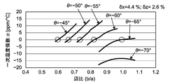
- the crystal plate 31 has a shape in which each side of the reference rectangle 30 is expanded outward. Therefore, the degree of bulging was examined to determine how good frequency temperature characteristics can be obtained.
- the degree of the bulge is represented by how much the bulge from the side of the reference rectangle 30 occupies the entire length.
- the side ratio (b / a) with respect to various rotation angles ⁇ that is, cutting orientations when cutting the rotating Y plate for constituting the quartz plate 31 is set.
- the change of the first-order temperature coefficient ⁇ at 25 ° C. in the frequency temperature characteristic when changed was obtained by simulation.
- the results are shown in FIG.
- the portion surrounded by a broken-line circle indicates that the primary temperature coefficient ⁇ is almost zero.
- the rotation angle ⁇ is in the range of ⁇ 70 ° to ⁇ 50 °
- the side ratio (b / a) is in the range of 0.60 to 0.98
- the primary temperature coefficient ⁇ is near room temperature. It is almost zero.
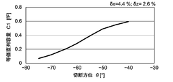
- FIG. 10 is a graph showing the relationship between the rotation angle ⁇ and the equivalent series capacitance C1.
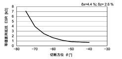
- FIG. 11 is a graph showing the relationship between the rotation angle ⁇ and the equivalent series resistance ESR.
- the rotation angle ⁇ decreases, the equivalent series capacitance C1 decreases and the equivalent series resistance ESR increases.
- the rotation angle ⁇ is smaller than ⁇ 65 °, the equivalent series resistance ESR increases rapidly. Therefore, when considering commercialization, the rotation angle ⁇ should be in the range of ⁇ 65 ° to ⁇ 50 °, and the side ratio (b / a) of the quartz plate should be in the range of 0.65 to 0.98. Is desirable.
- the resonance frequency is determined by the outer shape of the crystal plate. Even if the excitation electrode is formed as wide as possible with respect to the plate surface of the quartz plate, the equivalent series capacitance C1 is reduced and the equivalent series resistance ESR is increased to, for example, about 1 k ⁇ . Since the resonance frequency is determined by the outer shape, it is not possible to adopt a method of increasing the plane size of the quartz plate in order to reduce the equivalent series resistance ESR.
- the crystal resonator according to the present invention Compared to a generally used AT-cut crystal resonator, the crystal resonator according to the present invention has an equivalent series capacitance C1 that is reduced to a fraction, and the equivalent series resistance ESR is several times greater.
- the circuit configuration for achieving stable oscillation becomes complicated.
- the equivalent series resistance of the crystal resonator is large, the oscillation margin of the oscillation circuit decreases.
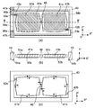
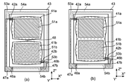
- This crystal resonator includes two crystal plates 41a and 41b having the same crystal orientation and outer shape as the crystal plate 31 described with reference to FIG. 3 in the first embodiment, and is provided in an opening of a frame (frame body) 43.
- the crystal plates 41a and 41b are held.
- the long side of each reference rectangle is parallel to the X ′′ axis and the short side is parallel to the Z ′′ axis. It is indicated by a one-dot chain line in the reference rectangle.
- the two quartz plates 41a and 41b are mechanically coupled to each other by the rod-like connecting member 48 so that their reference rectangles are aligned along the X ′′ axis.
- the quartz plates 41a and 41b are coupled to each other. Since they have the same outer shape, they have the same resonance frequency.
- the crystal plate 41a is supported by mechanically connecting to a rod-like support portion 42a extending along the X ′′ axis direction from the inner wall of the frame 43.
- the crystal plate 41b is also supported from the inner wall of the frame 43 in the X ′′ axis direction. Is supported by being mechanically connected to a rod-like support portion 42b extending along the axis.
- the position where the support portion 42a is connected to the crystal plate 41a is the outer periphery of the crystal plate 41a, and among the four points P 1 to P 4 where the displacement in the X ′′ axis direction is almost 0, P 1 or P 2
- the position where the support portion 42b is connected to the crystal plate 41b is either P 3 or P 4.
- the support portions 42a and 42b are different from the center line passing through the crystal plates 41a and 41b. Since the crystal plates 41a and 41b are mechanically coupled by the connecting member 48, the crystal plates 41a and 41b are supported as a whole by two-point support by the support portions 42a and 42b.
- the thickness of the frame 43 is sufficiently thicker than the thickness of the crystal plates 41a and 41b.
- the extending direction of the support portion can be the Z ′′ axis direction, but in this case, the crystal Position where the support part connects on the plate Is the position of the point on the outer periphery of the quartz plate where the displacement in the Z ′′ axis direction is almost zero.
- connection member 48 is disposed at a position of a center line (line BB ′ in the figure) passing through the crystal plates 41a and 41b.
- the position of the connecting member 48 is not limited to this, but if the positions of the above-mentioned points P 1 to P 4 on the crystal plates 41a and 41b are set, the significance of providing the connecting member 48 is lost, and both quartz crystals The plates 41a and 41b are not mechanically coupled.
- the quartz plates 41a and 41b, the support portions 42a and 42b, the frame 43 and the connection member 48 are integrally formed of quartz.
- a crystal wafer that is a rotating Y plate with a rotation angle ⁇ of ⁇ 65 ° or more and ⁇ 50 ° or less is prepared, and the crystal wafer 41a, 41b, the support portions 42a and 42b, the frame 43, and the connection member 48 can be integrally formed at the same time.
- the two crystal plates 41a and 41b are arranged in a plane stretched by the vibration directions of the two longitudinal vibration modes in the crystal resonator according to the present invention, and the support portion 42 and the connection member 48 are also in this plane. Will be placed.
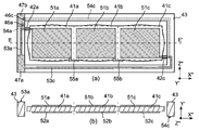
- the main surface shown on the paper surface in the plan view of the crystal resonator is called the surface of the crystal plate, and is located on the paper back side in the plan view Is called the back side of the crystal plate.
- the front and back surfaces of the frame and the support portion are defined.
- the excitation electrode 51a is formed on almost the entire surface, and the excitation electrode 52a is formed on the almost entire surface of the back surface.
- the excitation electrode 51b is formed on almost the entire surface, and the excitation electrode 52b is formed on almost the entire back surface.
- a pair of connection pads 47a and 47b are provided on the surface of the frame 43 in order to electrically connect the crystal resonator to an external circuit.
- the excitation electrode 51a formed on the surface of the crystal plate 41a is electrically connected to the connection pad 47a via the conductive path 53a formed on the surface of the frame 43 and the support portion 42a.
- the excitation electrode 52a formed on the back surface of the crystal plate 41a is further provided at the end of the conductive path 54a through the frame 43 and the conductive path 54a formed on the back surface of the support portion 42a. It is electrically connected to the connection pad 47b through the hole 46a.
- the excitation electrode 51b formed on the surface of the crystal plate 41b is electrically connected to the connection pad 47b via the conductive path 53b formed on the surface of the frame 43 and the support portion 42b.
- the excitation electrode 52b formed on the back surface of the crystal plate 41b is provided at the end of the conductive path 54b through the frame 43 and the conductive path 54b formed on the back surface of the support portion 42b. It is electrically connected to the connection pad 47a through the hole 46b.
- the conductive paths 54a and 54b correspond to the extraction electrodes in the crystal resonator of the first embodiment.
- the quartz plates 41a and 41b have opposite electrical polarities at the time of excitation.
- the crystal plate 41a extends in the Z ′′ axis direction and contracts in the X ′′ axis direction (in the case indicated by the solid line in the drawing)
- the crystal plate 41b extends in the X ′′ axis direction.
- the crystal plate 41a contracts in the Z ′′ axis direction and extends in the X ′′ axis direction (indicated by a broken line in the drawing)
- the crystal plate 41b contracts in the X ′′ axis direction.
- connection member 48 It extends in the Z ′′ axis direction. Assuming that the two crystal plates 41a and 41b vibrate in this way, the distance between both crystal plates 41a and 41b at the position of the connection member 48 hardly changes, and therefore the connection member 48 is connected to both crystal plates 41a. , 41b are mechanically coupled to each other, but the vibrations in the quartz plates are not hindered.
- both the quartz plates 41a and 41b are provided even when the resonance frequencies of the quartz plates 41a and 41b are slightly shifted from each other. And resonate at the same frequency, and a high Q value can be obtained as a crystal resonator.
- the connection member 48 is not provided, it is electrically equivalent to connecting two crystal resonators whose resonance frequencies are slightly shifted in parallel, and the Q value when viewed as a whole Will drop.
- each crystal plate 41a, 41b is supported by the support portion 42 at the point where the vibration displacement in the X ′′ axis direction or the Z ′′ axis direction on the outer periphery is minimized. 42 does not affect the vibration characteristics of the quartz plates 41a and 41b.
- the connection member 48 mechanically couples the two crystal plates 41a and 41b, the connection member 48 does not inhibit the vibration of the crystal plates 41a and 41b. Since the quartz plates 41a and 41b have the same resonance frequency, the quartz plates 41a and 41b vibrate at the common resonance frequency and are coupled across the quartz plates 41a and 41b even when viewed as a whole crystal resonator. Thus, it vibrates stably in one vibration mode. As a result, this quartz crystal vibrator vibrates extremely stably without causing side vibration.
- the crystal resonator shown in FIG. 12 has the same resonance frequency, but the area of the excitation electrode is doubled, so the equivalent series capacitance C1 is also doubled.
- the equivalent series resistance ESR is halved. Therefore, when the crystal resonator shown in FIG. 12 is applied to an oscillation circuit, the equivalent series resistance is small, so that a large oscillation margin can be achieved with a simple circuit configuration, and a highly stable oscillation circuit can be configured. .
- FIG. 12 shows a crystal resonator according to the second embodiment, which has a configuration in which crystal plates 41a and 41b are mechanically coupled directly.
- connection member 48 is removed from the crystal resonator shown in FIGS. 12A and 12B, and instead of the reference rectangular shape of the crystal plate 41a.
- the outer peripheries of the quartz plates 41a and 41b have a shape in which each side of each reference rectangle is expanded outward except for the sides shared by both the quartz plates 41a and 41b.
- the crystal pieces 41a and 41b have a symmetrical shape with respect to the common side and have the same resonance frequency. Therefore, the crystal resonator shown in FIG. 13 vibrates in the same manner as the crystal resonator shown in FIG. 12, and has twice the equivalent series capacitance C1 and half the equivalent series resistance as compared with the crystal resonator of the first embodiment. Will have ESR.
- quartz resonator In the quartz resonator according to the second embodiment, two quartz plates 41a and 41b whose length in the X ′′ axis direction is longer than the length in the Z ′′ axis direction are arranged in the Z ′′ axis direction to mechanically A quartz crystal unit coupled to is shown.
- the two crystal plates 41a and 41b are mechanically coupled by the connecting member 48 in the same manner as that shown in FIG.
- the crystal plates 41a and 41b are integrated so that the reference rectangles of both the crystal plates 41a and 41b share one side parallel to the X ′′ axis. It shows what was converted.
- the crystal unit is composed of the two crystal plates 41a and 41b.
- three or more crystal plates described with reference to FIG. 3 are used, and three or more crystal plates are used.
- FIGS. 15A and 15B show an example of the crystal resonator of the third embodiment.
- This crystal resonator is the same as the crystal resonator shown in FIG. 12, but has a structure in which three crystal plates 41a to 41c are connected instead of two. More specifically, in this crystal resonator, three crystal plates 41 a to 41 c having the same crystal orientation and outer shape as the crystal plate 31 described with reference to FIG. 3 in the first embodiment are placed in the opening of the frame 43. It has a retained structure.
- the quartz plates 41a and 41b are mechanically coupled to each other by a connecting member 48a, and the quartz plates 41b and 41c are mechanically coupled to each other by a connecting member 48b.
- the long side of each reference rectangle is parallel to the X ′′ axis and the short side is parallel to the Z ′′ axis.
- the quartz plates 41a to 41c are arranged so that their reference rectangles are aligned along the X ′′ axis. Since the quartz plates 41a to 41c have the same outer shape, they have the same resonance frequency. Yes.
- the crystal plate 41a is mechanically connected to the frame 43 via the support portion 42a
- the crystal plate 41c is mechanically connected to the frame 43 via the support portion 42c. Is held in.
- the positions where the support portions 42a and 42c are connected to the quartz plates 41a and 41c are the outer circumferences of the quartz plates 41a and 41c as in the case of the second embodiment described above, and the displacement in the X ′′ axis direction described above is the same.
- the crystal plates 41a to 41c, the support portions 42a and 42c, the frame 43, and the connection members 48a and 48b are integrally formed of crystal, in the example shown here, the connection member 48a. , 48b are arranged at the position of the center line (DD ′ line in the figure) passing through the quartz plates 41a to 41c.
- excitation electrodes 51a and 52a are formed on almost the entire surface and the back surface of the crystal plate 41a, respectively, and similarly, on the front and back surfaces of the crystal plate 41b, respectively.
- Excitation electrodes 51b and 52b are formed on almost the entire surface
- excitation electrodes 51c and 52c are formed on the almost entire surface on the front and back surfaces of the crystal plate 41c, respectively.
- a pair of connection pads 47a and 47b are provided on the surface of the frame 43 in order to electrically connect the crystal resonator to an external circuit.
- the excitation electrode 51a formed on the surface of the crystal plate 41a is electrically connected to the connection pad 47a via the conductive path 53a formed on the surface of the frame 43 and the support portion 42a.
- the excitation electrode 52a formed on the back surface of the crystal plate 41a is further provided at the end of the conductive path 54a through the frame 43 and the conductive path 54a formed on the back surface of the support portion 42a. It is electrically connected to the connection pad 47b through the hole 46a.
- the excitation electrode 51c formed on the surface of the crystal plate 41c is electrically connected to the connection pad 47a via the conductive path 53c formed on the surface of the frame 43 and the support portion 42c.
- the excitation electrode 52c formed on the back surface of the quartz plate 41c is further provided at the end of the conductive path 54c through the frame 43 and the conductive path 54c formed on the back surface of the support portion 42c. It is electrically connected to the connection pad 47b through the hole 46c.
- the crystal plates 41a and 41c are connected to the support portions 41a and 41c, so that the electrodes can be drawn out through the conductive paths formed in the support portions 41a and 41c.
- the support portion is not connected to the crystal plate 41b sandwiched between the crystal plates 41a and 41c, the electrode cannot be drawn from the crystal plate 41b as it is. Therefore, in the crystal resonator shown in FIG. 15, a conductive path 55a passing through the surface of the connecting member 48a between the crystal plates 41a and 41b is provided, and the excitation electrode 52b on the back surface of the crystal plate 41b is connected to the crystal plate 41a by the conductive path 55a. It is connected to the excitation electrode 51a on the surface.
- the excitation electrode 51b on the surface of the crystal plate 41b is connected to the excitation electrode 52c on the back surface of the crystal plate 41c by a conductive path 55b provided on the surface of the connection member 48b between the crystal plates 41b and 41c.
- the excitation electrodes 51a, 52b, and 51c are electrically connected to the connection pad 47a
- the excitation electrodes 52a, 51b, and 52c are electrically connected to the connection pad 47b.
- the quartz plates 41a and 41b have opposite polarities when excited, and the quartz plates 41b and 41c also have opposite polarities.
- the quartz plates 41a and 41c have the same polarity.
- the crystal plates 41a to 41c vibrate at a common resonance frequency, and even when viewed as a whole crystal unit, the crystal plates 41a to 41c stably vibrate in one vibration mode coupled across the crystal plates 41a to 41c. Will do.
- the area of the excitation electrode is tripled while the resonance frequency is the same, so the equivalent series capacitance C1 is also tripled.
- the equivalent series resistance ESR becomes one third.
- the crystal resonator based on the third embodiment is not limited to the one shown in FIG.
- the crystal resonators shown in FIGS. 16A and 16B are the same as those shown in FIGS. 15A and 15B, but the crystal plates 41a to 41c are directly attached without using connection members. It is constructed by joining.
- the right side of the reference rectangle of the crystal plate 41a and the left side of the reference rectangle of the crystal plate 41b are in contact with each other, and the right side of the reference rectangle of the crystal plate 41 and the left side of the reference rectangle of the crystal plate 41c are mutually connected.
- Three crystal plates 41a to 41c are integrated so as to be in contact with each other.
- the quartz plates 41a to 41c are arranged along the X ′′ axis direction.
- the outer circumferences of the quartz plates 41a to 41c are the sides of each reference rectangle except for the sides shared by other reference rectangles.
- the shape is inflated outward.
- the quartz plates 41a and 41c located at the ends of the integrally formed quartz resonator and the quartz plate 41b located in the middle have a slight difference in resonance frequency when the dimensions of the reference rectangle are the same. there is a possibility. Therefore, for the purpose of matching the resonance frequency, the bulge of the outer peripheral side of the quartz plate 41b may be made different from that of other quartz plates.
- the conductive path 55a that electrically connects the excitation electrode 51a of the crystal plate 41a and the excitation electrode 52b of the crystal plate 41b is provided between the crystal plates 41a and 41b. It is formed on the side surfaces of the crystal plates 41a and 41b so as to straddle the coupling portion.
- a conductive path 55b that electrically connects the excitation electrode 51b of the crystal plate 41b and the excitation electrode 52c of the crystal plate 41c is formed on the side surface of the crystal plates 41b and 41c so as to straddle the coupling portion of the crystal plates 41b and 41c.
- the crystal resonator shown in FIG. 16 also vibrates in the same manner as the crystal resonator shown in FIG. 15, and is equivalent to three times the equivalent series capacitance C1 and one-third equivalent series as compared with the crystal resonator of the first embodiment. It will have resistance ESR.
- 17 (a) and 17 (b) respectively show X ′′ axial directions in the planes of the quartz plates 41a to 41c when the quartz crystal resonator shown in FIG. 16 vibrates in the width / length longitudinally coupled vibration mode.
- required the distribution of the amount of displacement, and the distribution of the amount of displacement of a Z "axial direction by simulation is shown.
- a positive displacement amount indicates a displacement in the positive direction of each axis
- a negative displacement amount indicates a displacement in the negative direction.
- the influence of holding by the support portion is not considered.
- the quartz plate 41a there are two points on the outer periphery that is in the vicinity of the apex on the left edge side in the figure, and the displacement in the X ′′ axis direction is substantially 0. There are two points where the displacement in the X ′′ axis direction is almost zero on the outer periphery near the vertex on the side. At these points, the displacement in the Z ′′ axis direction is also relatively small. Therefore, by connecting a thin rod-shaped support portion to some of these points, the vibration characteristics are not adversely affected. It can be seen that the entire quartz plates 41a to 41c can be supported.
- FIGS. 15 and 16 three crystal plates 41a to 41c whose length in the X ′′ axis direction is longer than the length in the Z ′′ axis direction are mechanically arranged in the X ′′ axis direction.
- the elastic modulus C ′ 11 in the X ′′ axial direction and the elastic modulus C ′ 33 in the Z ′′ axial direction are both the same.
- quartz resonator In the quartz resonator according to the third embodiment, three quartz plates 41a to 41c whose length in the X ′′ axis direction is longer than the length in the Z ′′ axis direction are arranged in the Z ′′ axis direction to mechanically A quartz crystal unit coupled to is shown.
- the three crystal plates 41a to 41c are mechanically coupled by the connection members 48a and 48b in the same manner as that shown in FIG.
- FIG. 18 (b) is a structure in which three crystal plates 41a to 41c are directly coupled as shown in FIG. 16, but the arrangement direction of the crystal plates 41a to 41c is the Z ′′ axis. Is different from that shown in FIG.
- the quartz crystal unit according to the present invention which is a quartz crystal plate mechanically coupled with three quartz plates having substantially the same resonance frequency.
- the number is not limited to three.
- four or more quartz plates are arranged along the X ′′ axis direction or the Z ′′ axis direction and mechanically coupled, and excitation electrodes are connected so that the adjacent quartz plates are excited with opposite polarity.
- By setting the conductive path it is possible to configure a crystal resonator having a larger equivalent series capacitance C1 and a smaller equivalent series resistance ESR.
Abstract
[Problem] To provide a crystal oscillator that can be fitted with a small and simple-structured support part without adversely affecting an oscillation characteristic, and that has an excellent frequency-temperature characteristic with a high degree of design flexibility.
[Solution] Crystallographic X-axis, Y-axis, and Z-axis of a crystal are rotated by -65° to -50° about the X-axis and defined as an X'-axis, a Y'-axis, and a Z'-axis, respectively, and the X'-axis and the Z'-axis are rotated by 40° to 50° about the Y'-axis and defined as an X"-axis and a Z"-axis, respectively. With reference to a reference rectangle which is a rectangle having sides parallel to the X"-axis and the Z"-axis, the crystal oscillator uses a crystal plate 31 that has a shape obtained by expanding at least a pair of opposite sides of the reference rectangle toward the outside of the reference rectangle, and that has longitudinal oscillation modes in the X"-direction and the Z"-direction.
Description
本発明は、水晶振動子に関する。
The present invention relates to a crystal resonator.
周波数や時間の基準源として用いられる水晶振動子は、水晶振動子を構成する振動板すなわち水晶板を水晶の単結晶から切り出すときの結晶学的な方位にしたがって、何種類かの“カット”に分類される。そのようなカットとしては、従来から、例えば、ATカット、SCカットなどが広く知られている。中でもGTカットの水晶板は、優れた周波数温度特性を有し、周囲温度が変化した場合における共振周波数の変化が非常に小さいので、高精度高安定の水晶発振器への適用などが期待されている。長方形状のGTカットの水晶振動子は、低周波数帯(例えば、2~10MHz)において小型化が可能であり、常温(25℃近傍)で一次の温度係数が0となるような周波数温度特性を有している。
Quartz resonators used as frequency and time reference sources are divided into several types of “cuts” according to the crystallographic orientation of the crystal plates that make up the crystal units, that is, when the crystal plates are cut from a single crystal of crystal. being classified. As such cuts, for example, AT cuts, SC cuts, and the like are widely known. Among them, the GT-cut quartz plate has excellent frequency temperature characteristics, and the change in the resonance frequency when the ambient temperature changes is very small. Therefore, it is expected to be applied to a highly accurate and stable crystal oscillator. . The rectangular GT-cut crystal resonator can be downsized in a low frequency band (for example, 2 to 10 MHz), and has a frequency temperature characteristic such that the primary temperature coefficient becomes 0 at room temperature (around 25 ° C.). Have.
水晶においては、周知なように、結晶学的にX軸、Y軸及びZ軸の3本の結晶軸が定められている。Y軸に直交する面(すなわち、X軸とZ軸に平行な面)に沿って切り出される水晶板をY板と呼ぶが、Y板をX軸の周りに+51.5°回転させ(すなわちθ=+51.5°)、さらにその板の面内で板を+45°回転させる(すなわちβ=+45°)ことによって形成される水晶板からなるカットがGTカットである(例えば、特許文献1参照)。θ及びβは、水晶におけるカット方位を特定するために一般的に用いられるパラメータである。GTカットの水晶板内での方位を指定するために、X軸、Y軸及びZ軸をX軸の周りで上記の+51.5°回転させて得られる軸をそれぞれX’軸、Y’軸及びZ’軸とする。X軸周りの回転であるので、当然のことながらX’軸はX軸に一致する。そして、X’軸及びZ’軸をY’軸の周りでZ’軸からX’軸に向かう方向に45°回転させて得られる軸をそれぞれX”軸及びZ”軸とする。
As is well known, quartz crystal has three crystal axes that are crystallographically defined as an X axis, a Y axis, and a Z axis. A quartz crystal plate cut along a plane perpendicular to the Y axis (that is, a plane parallel to the X axis and the Z axis) is called a Y plate, and the Y plate is rotated around the X axis by + 51.5 ° (that is, θ = + 51.5 °) and a cut made of a quartz plate formed by rotating the plate by + 45 ° within the plane of the plate (ie, β = + 45 °) is a GT cut (see, for example, Patent Document 1). . θ and β are parameters generally used to specify the cut direction in the crystal. In order to specify the orientation of the GT cut crystal plate, the X, Y, and Z axes are obtained by rotating the X, Y, and Z axes around the X axis by + 51.5 °, respectively. And the Z ′ axis. Since the rotation is about the X axis, the X ′ axis naturally coincides with the X axis. The axes obtained by rotating the X ′ axis and the Z ′ axis by 45 ° around the Y ′ axis in the direction from the Z ′ axis to the X ′ axis are defined as an X ″ axis and a Z ″ axis, respectively.
ここでGTカットの水晶板における振動モードを説明する。図1に示すように、GTカットの水晶板11における振動モードは、X”軸方向の縦振動(伸縮振動)モードとZ”軸方向の縦振動モードとが結合した振動モード(幅・長さ縦結合振動モードともいう)である。図において、伸縮振動の方向が矢印で示されており、振動によって変位した輪郭が破線によって示されている。ただし、説明のために、変位した輪郭は、水晶板11における実際の変位量よりもはるかに大きな変位をしたものとして描かれている。2つの縦振動モードが結合した振動モードであるため、従来、GTカットの水晶板は、1対の辺がX”軸に平行となり、もう1対の辺がZ”軸に平行になるような長方形あるいは角型の形状にして、水晶振動子における振動板として用いられていた。振動板としての水晶板を励振するための励振電極は、水晶板の両方の主面にそれぞれ設けられる。縦振動モードを主振動として利用することから、GTカットの水晶板は、共振周波数が低周波帯にあるときであっても、小型に形成することができる。なお、GTカットの振動子は、各辺の長さを等しくし正方形の振動板とした場合には、幅・長さ縦結合振動モードとは異なるラーメ振動モードと呼ばれる振動モードで振動するので、原則として、GTカットの振動子の平面形状は正方形とはしない。
Here, the vibration mode in the GT-cut quartz plate will be described. As shown in FIG. 1, the vibration mode of the GT-cut quartz plate 11 is a vibration mode (width / length) in which a longitudinal vibration (stretching vibration) mode in the X ″ axis direction and a longitudinal vibration mode in the Z ″ axis direction are combined. Also referred to as a longitudinally coupled vibration mode). In the figure, the direction of the stretching vibration is indicated by an arrow, and the contour displaced by the vibration is indicated by a broken line. However, for the sake of explanation, the displaced contour is depicted as being much larger than the actual amount of displacement in the quartz plate 11. Since the two longitudinal vibration modes are combined, the conventional GT-cut quartz plate has a pair of sides parallel to the X ″ axis and another pair of sides parallel to the Z ″ axis. A rectangular or square shape was used as a diaphragm in a crystal resonator. Excitation electrodes for exciting the crystal plate as the vibration plate are respectively provided on both main surfaces of the crystal plate. Since the longitudinal vibration mode is used as the main vibration, the GT-cut quartz plate can be formed in a small size even when the resonance frequency is in the low frequency band. Note that the GT-cut vibrator vibrates in a vibration mode called a lame vibration mode different from the width / length longitudinally coupled vibration mode when the length of each side is equal and a square diaphragm is used. In principle, the plane shape of the GT-cut vibrator is not square.
水晶板の振動モードは、カットごとに異なっている。例えば、従来から広く用いられているATカットの水晶板の場合、振動モードは厚み滑り振動モードであって、その厚さのみによって共振周波数が決定する。そのためATカットの水晶板では、平面形状を任意に設定することができ、これにより、厚み滑り振動での不動点となる位置で水晶片を支持する構成とすることができる。しかしながらGTカットの水晶片の場合、振動モードが幅・長さ縦結合振動モードであって幅や長さなどの平面形状やサイズに応じて共振周波数が変化し、かつ、相互に結合する2つの振動モードの振動が両方とも確実に起きるようにしなければならないから、平面形状を任意に設定したり、任意の位置に支持部を配置したりすることはできない。特に、長方形状のGTカットの水晶板の外周部には、一般的には、振動変位における不動点は存在しない。
The vibration mode of the quartz plate is different for each cut. For example, in the case of an AT-cut quartz plate that has been widely used conventionally, the vibration mode is a thickness-shear vibration mode, and the resonance frequency is determined only by the thickness. Therefore, in the AT-cut quartz plate, the plane shape can be arbitrarily set, and thereby, the quartz piece can be supported at a position that becomes a fixed point in the thickness shear vibration. However, in the case of a GT-cut crystal piece, the vibration mode is the width / length longitudinally coupled vibration mode, the resonance frequency changes according to the planar shape and size such as width and length, and the two coupled to each other. Since it is necessary to ensure that both vibrations in the vibration mode occur, the planar shape cannot be arbitrarily set, and the support portion cannot be arranged at any position. In particular, there is generally no fixed point for vibration displacement on the outer periphery of a rectangular GT-cut quartz plate.
水晶振動子を構成する振動板すなわち水晶片としてGTカットの水晶板を使用する場合には、水晶振動子の容器の壁面などと接触しないように水晶板を容器内に保持する必要があるが、長方形状のGTカットの水晶板の外周部には振動変位における不動点は存在しないから、できるだけ、振動を妨げないような位置と形状で、水晶片に対する支持部を設ける必要がある。そこで、特許文献2に示されるように、フォトリソグラフィ技術を用いることにより、振動板の本体部分(振動部)とそれに対する支持部とを水晶の板状部材から一体的に形成することが提案されている。その場合、図2に示すように、振動板としての水晶板11の長方形状の本体部分における対向する1対の辺の各々の中点の位置に対し、支持部12が接続するようにする。このとき、クランク状の折れ曲がり部を設けるなどして支持部12が水晶板11の振動に影響を及ぼさないようにする。さらに、有限要素法などの手法を用いることによって、振動部単独での共振周波数と、支持部12までを含めた共振系全体としての共振周波数とがほぼ同じになるように、支持部12の形状を設計する。
When using a GT-cut quartz plate as a diaphragm constituting a quartz crystal unit, that is, a crystal piece, it is necessary to hold the quartz plate in the container so as not to contact the wall surface of the quartz crystal container. Since there is no fixed point for vibration displacement on the outer periphery of the rectangular GT-cut quartz plate, it is necessary to provide a support for the quartz piece in a position and shape that does not hinder vibration as much as possible. Therefore, as disclosed in Patent Document 2, it has been proposed to integrally form the main body portion (vibrating portion) of the vibration plate and the supporting portion thereof from a quartz plate-like member by using a photolithography technique. ing. In this case, as shown in FIG. 2, the support portion 12 is connected to the midpoint position of each of a pair of opposing sides in the rectangular main body portion of the crystal plate 11 as the vibration plate. At this time, the support part 12 does not affect the vibration of the quartz plate 11 by providing a crank-like bent part. Further, by using a method such as the finite element method, the shape of the support portion 12 is set so that the resonance frequency of the vibration portion alone and the resonance frequency of the entire resonance system including the support portion 12 are substantially the same. To design.
しかしながら、図2に示したような支持部を備えるGTカットの水晶振動子は、構造が複雑であって製造が難しく、また支持部自体の大きさが振動板の本体部分に比べて無視できないので、支持部における寸法ばらつきが水晶板の振動特性に大きな影響を及ぼすとともに、水晶振動子の小型化を阻害する、という課題を有する。
However, a GT-cut quartz crystal resonator having a support portion as shown in FIG. 2 is complicated in structure and difficult to manufacture, and the size of the support portion itself cannot be ignored compared to the main body of the diaphragm. In addition, there is a problem that the dimensional variation in the support portion has a great influence on the vibration characteristics of the quartz plate and inhibits the miniaturization of the quartz resonator.
そこで本発明者らは、GTカットの水晶振動子として、楕円形状の水晶板を振動板として用いることを提案した(特許文献3)。GTカットにおける直交する2つの縦振動モードの振動方向をそれぞれ長軸と短軸とする楕円形に形成された水晶板では、2つの縦振動モードが結合したときに水晶板の外周において振動変位が極小となる位置が4点存在するようになるので、そのような点で水晶板を支持する構成とすることによって、簡単な構造の支持部を用いた場合であっても、水晶振動子としての振動特性に悪影響を与えることなく、水晶板を支持できるようになる。さらに本発明者らは、GTカットの水晶振動子において等価直列容量C1を大きくし等価直列抵抗ESRを小さくするために、それぞれが共振子として動作する複数の楕円形状のGTカットの水晶板を機械的に連結した水晶振動子を提案した(特許文献4)。
Therefore, the present inventors have proposed to use an elliptical crystal plate as a diaphragm as a GT-cut crystal resonator (Patent Document 3). In the quartz plate formed in an elliptical shape in which the vibration directions of two orthogonal longitudinal vibration modes in the GT cut are the major axis and the minor axis, respectively, vibration displacement occurs on the outer periphery of the quartz plate when the two longitudinal vibration modes are combined. Since there are four positions that are minimal, by adopting a structure that supports the crystal plate at such points, even when a support portion with a simple structure is used, The quartz plate can be supported without adversely affecting the vibration characteristics. Furthermore, the present inventors have used a plurality of elliptical GT-cut quartz plates each acting as a resonator to increase the equivalent series capacitance C1 and reduce the equivalent series resistance ESR in a GT-cut quartz crystal resonator. Proposed a crystal resonator that is connected in a mechanical manner (Patent Document 4).
GTカットの水晶振動子では、その形状によって、周波数、振動特性及び周波数温度特性が決まる。特許文献3に示したような楕円形状のGTカットの水晶板を用いた場合、楕円としての形状(特に、長軸と短軸の長さの比)によって周波数温度特性が決まるため、所望の諸特性を有する水晶振動子を得ようとした場合に、設計の自由度が限られてしまう、という課題がある。
The frequency, vibration characteristics, and frequency temperature characteristics are determined by the shape of a GT-cut crystal resonator. When an elliptical GT-cut quartz plate as shown in Patent Document 3 is used, the frequency-temperature characteristics are determined by the shape of the ellipse (particularly, the ratio of the length of the major axis to the minor axis). When trying to obtain a crystal resonator having characteristics, there is a problem that the degree of freedom in design is limited.
本発明の目的は、振動特性に悪影響を及ぼすことなく小型で簡単な構造の支持部を設けることができ、かつ、周波数、振動特性及び周波数温度特性を含む各種の特性に関する設計の自由度が高い水晶振動子を提供することにある。
An object of the present invention is to provide a support portion having a small and simple structure without adversely affecting vibration characteristics, and has a high degree of freedom in designing various characteristics including frequency, vibration characteristics, and frequency temperature characteristics. The object is to provide a crystal resonator.
本発明の水晶振動子は、水晶の結晶学的なX軸、Y軸及びZ軸をX軸の周りに-65°以上-50°以下の角度だけ回転して得られた軸をそれぞれX’軸、Y’軸及びZ’軸とし、X’軸及びZ’軸をY’軸の周りでZ’軸からX’軸に向かう方向に40°以上50°以下の角度だけ回転させて得られる軸をそれぞれX”軸及びZ”軸として、X”軸及びZ”軸を含む面に平行に水晶から切り出された水晶板を備え、水晶板は、X”軸及びZ”軸にそれぞれ平行な辺を有する長方形を基準長方形として、基準長方形の少なくとも1対の対向する辺を基準長方形の外方に膨らませた形状を有して、X”軸方向及びZ”軸方向をそれぞれ振動方向とする直交する2つの縦振動モードを有する。
The crystal resonator of the present invention is obtained by rotating the crystallographic X-axis, Y-axis, and Z-axis of the crystal by an angle of −65 ° or more and −50 ° or less around the X-axis. Obtained by rotating the X ′ axis and the Z ′ axis around the Y ′ axis by an angle of 40 ° to 50 ° in the direction from the Z ′ axis to the X ′ axis. A crystal plate is cut out from the crystal parallel to the plane including the X ″ axis and the Z ″ axis, with the axes being the X ″ axis and the Z ″ axis, and the crystal plate is parallel to the X ″ axis and the Z ″ axis, respectively. A rectangle having sides is defined as a reference rectangle, and at least one pair of opposite sides of the reference rectangle is expanded outward from the reference rectangle, and the X ″ axis direction and the Z ″ axis direction are orthogonal directions. Have two longitudinal vibration modes.
本発明の水晶振動子は、GTカットの水晶振動子と同様に、いわゆるY板を水晶のX軸の周りに回転させ、さらに、面内で40°以上50°以下の角度だけ回転させた水晶板を振動板として用いるものである。したがって振動板は、いわゆる回転Y板によって構成されることになる。本発明の水晶振動子がGTカットの水晶振動子と異なるところは、水晶のY板をX軸の周りで回転するときの回転角θを-65°≦θ≦-50°の範囲で定めることである。θが-54°から-48°の間にあるときは一般にLQ2Tカットの水晶板と呼ばれるが、本発明では水晶板の形状を以下に述べるように単純な長方形とはしないので、好ましい特性を得るためにθの値を一般的なLQ2Tカットにおける値よりも小さく(負の値なので絶対値としては大きく)することができる。回転角θは、振動板となるべき回転Y板を水晶の結晶体から切り出すときの切断角度でもある。
The crystal resonator of the present invention is a crystal in which a so-called Y plate is rotated around the X axis of the crystal and further rotated in the plane by an angle of 40 ° or more and 50 ° or less, like the GT-cut crystal resonator. A plate is used as a diaphragm. Therefore, the diaphragm is constituted by a so-called rotating Y plate. The difference between the crystal resonator of the present invention and the GT-cut crystal resonator is that the rotation angle θ when the crystal Y plate is rotated around the X axis is determined in the range of −65 ° ≦ θ ≦ −50 °. It is. When θ is between −54 ° and −48 °, it is generally called an LQ 2 T-cut quartz plate. However, in the present invention, the shape of the quartz plate is not a simple rectangle as described below. In order to obtain the value, the value of θ can be made smaller than the value in a general LQ 2 T cut (because it is a negative value, it is larger as an absolute value). The rotation angle θ is also a cutting angle when a rotating Y plate to be a vibration plate is cut out from a crystal of crystal.
また本発明では、水晶板の形状を、X”軸及びZ”軸にそれぞれ平行な辺を有する長方形(これを基準長方形と呼ぶ)とするのではなく、この基準長方形の少なくとも1対の対向する辺を基準長方形の外方に膨らませた形状とする。好ましくは、水晶板の形状は、基準長方形の4つの辺の各々をその基準長方形の外方に膨らませた形状とする。基準長方形自体は、水晶板の形状を定義するために導入された仮想的なものであり、実際の水晶板では、基準長方形の内部であるか外部であるかによって性状等に格別の相違があるわけではない。また、基準長方形の形状は正方形であってもよいが、ラーメ振動モードが励起されることを防ぐためには、水晶板におけるX”軸方向の最大寸法とZ”軸方向の最大寸法とが異なるか、または、膨らみの形状が異なる必要がある。
Further, in the present invention, the shape of the crystal plate is not a rectangle having sides parallel to the X ″ axis and the Z ″ axis (referred to as a reference rectangle), but at least a pair of the reference rectangles face each other. The side is bulged outward from the reference rectangle. Preferably, the crystal plate has a shape in which each of the four sides of the reference rectangle is expanded outward from the reference rectangle. The reference rectangle itself is a virtual one introduced to define the shape of the crystal plate, and the actual crystal plate has a particular difference in properties depending on whether it is inside or outside the reference rectangle. Do not mean. In addition, the shape of the reference rectangle may be a square, but in order to prevent excitation of the lame vibration mode, is the maximum dimension in the X ″ axis direction different from the maximum dimension in the Z ″ axis direction in the quartz plate? Or, the shape of the bulge needs to be different.
本発明の水晶振動子では、水晶板の外周において、基準長方形の頂点の近傍の位置であって2つの縦振動モードが結合したときにX”軸方向またはZ”軸方向の振動変位が極小となる位置が存在する。そこでこの位置において水晶板を支持することが好ましい。例えばこの位置において水晶板の外周に対して支持部を接続することにより、水晶板を支持することが好ましい。
In the crystal resonator according to the present invention, the vibration displacement in the X ″ axis direction or the Z ″ axis direction is minimal when the two longitudinal vibration modes are combined at the position near the apex of the reference rectangle on the outer periphery of the crystal plate. There is a position. Therefore, it is preferable to support the quartz plate at this position. For example, it is preferable to support the crystal plate by connecting a support portion to the outer periphery of the crystal plate at this position.
さらに本発明では、X”軸方向あるいはZ”軸方向に沿って上述した水晶板を複数個配列し、各水晶板ごとに当該水晶板の両方の主面にそれぞれ励振電極を設け、隣接する水晶板を相互に機械的に結合し、かつ、隣接する水晶板が相互に逆極性で励振されるように励振電極間に導電路を形成してもよい。
Furthermore, in the present invention, a plurality of the above-described crystal plates are arranged along the X ″ axis direction or the Z ″ axis direction, and excitation electrodes are provided on both main surfaces of the crystal plates for each crystal plate. The plates may be mechanically coupled to each other and conductive paths may be formed between the excitation electrodes so that adjacent quartz plates are excited with opposite polarities.
本発明によれば、Y板をX軸の周りに回転させた上で面内で40°以上50°以下の角度だけ回転させて得られる水晶板であって、X”軸及びZ”軸にそれぞれ平行な辺を有する長方形(基準長方形)からさらに基準長方形の各辺を外方に膨らませた形状の水晶板を用いることによって、振動特性や周波数温度特性を所望のものとすることが可能となり、水晶振動子の設計の自由度が高くなる。この場合、単純な楕円形状のGTカットの水晶板に比べ、良好な周波数温度特性を得ながら、X”軸方向の最大寸法とZ”軸方向の最大寸法との比を1に近づけることが可能となり、振動子のさらなる小型化が可能になる。また、振動変位が極小となる点で水晶板を保持することが可能となって、振動特性に影響を及ぼすことなく、小型で簡単な構造の支持部を使用した水晶振動子を構成することができる。本発明の水晶振動子は、縦振動モードを主振動として利用するため、低周波帯においても小型化することができる。
According to the present invention, there is provided a quartz plate obtained by rotating a Y plate around the X axis and then rotating the Y plate by an angle of not less than 40 ° and not more than 50 ° in the plane, and the X ″ axis and the Z ″ axis. By using a quartz plate in which each side of the reference rectangle is further expanded outward from a rectangle having parallel sides (reference rectangle), it becomes possible to make vibration characteristics and frequency temperature characteristics desired, The degree of freedom in designing crystal units increases. In this case, the ratio of the maximum dimension in the X ″ axis direction to the maximum dimension in the Z ″ axis direction can be made close to 1 while obtaining better frequency temperature characteristics than a simple elliptical GT-cut quartz plate. Thus, the vibrator can be further downsized. In addition, it is possible to hold the quartz plate at a point where the vibration displacement is minimized, and it is possible to construct a quartz resonator using a small and simple structure supporting portion without affecting the vibration characteristics. it can. Since the crystal resonator of the present invention uses the longitudinal vibration mode as the main vibration, it can be miniaturized even in a low frequency band.
以下に、本発明を実施するための形態について図面を参照して説明する。
Hereinafter, embodiments for carrying out the present invention will be described with reference to the drawings.
図3(a)~(d)は、いずれも、本発明の第1の実施形態における水晶振動子において振動板として用いられる水晶板31の平面形状の例を示している。これらの水晶板31は、いずれも、Y板(水晶の結晶学的なY軸に垂直な面)を水晶のX軸の周りに角度θだけ回転させ、さらに、面内で40°以上50°以下の角度だけ回転させた水晶板である。ここで回転角θは-65°≦θ≦-50°の範囲にある。ここで水晶の結晶学的なX軸、Y軸、Z軸をX軸の周りに角度θだけ回転して得られる座標軸をX’軸、Y’軸、Z’軸とし(したがって、X’軸はX軸に一致する)、さらにX’軸及びZ’軸をZ’軸からX’軸に向かう方向に40°以上50°以下の角度だけ回転させて得られる軸をそれぞれX”軸及びZ”軸とすると、水晶板31は、X”軸及びZ”軸に平行な面を有する水晶板31ということになる。水晶板31は、X”軸方向及びZ”軸方向をそれぞれ振動方向とする直交する2つの縦振動モードを有し、かつこれらの縦振動モードが結合して、X”軸方向とZ”軸方向とに交互に伸縮する幅・長さ縦結合振動モードを有することになる。ここで述べたX’軸、Y’軸、Z’軸、X”軸及びZ”軸の定義は、以下の説明、及び図3とそれ以降の図面においても共通である。
3A to 3D show examples of the planar shape of the crystal plate 31 used as the vibration plate in the crystal resonator according to the first embodiment of the present invention. Each of these quartz plates 31 rotates a Y plate (a plane perpendicular to the crystallographic Y-axis of the quartz crystal) around the X-axis of the quartz by an angle θ, and further 40 ° to 50 ° in the plane. A quartz plate rotated by the following angle. Here, the rotation angle θ is in the range of −65 ° ≦ θ ≦ −50 °. Here, the coordinate axes obtained by rotating the crystallographic X-axis, Y-axis, and Z-axis around the X-axis by an angle θ are defined as the X′-axis, the Y′-axis, and the Z′-axis (therefore, the X′-axis). And X ′ axis and Z ′ axis are rotated by an angle of 40 ° or more and 50 ° or less in the direction from the Z ′ axis to the X ′ axis, respectively. Assuming that it is “axis”, the quartz plate 31 is a quartz plate 31 having a plane parallel to the X ″ axis and the Z ″ axis. The quartz plate 31 has two orthogonal longitudinal vibration modes whose vibration directions are the X ″ axis direction and the Z ″ axis direction, respectively, and these longitudinal vibration modes are combined to form the X ″ axis direction and the Z ″ axis. It has a width-length longitudinally coupled vibration mode that alternately expands and contracts in the direction. The definitions of the X ′ axis, the Y ′ axis, the Z ′ axis, the X ″ axis, and the Z ″ axis described here are common to the following description and FIG. 3 and subsequent drawings.
ここで、仮想的にX”軸及びZ”軸にそれぞれ平行な辺を有する長方形を基準長方形30として考えると、第1の実施形態に基づく水晶板31は、基準長方形30の4つの辺の各々を基準長方形30の外方に膨らませた形状を有する。図において基準長方形は一点鎖線で示されている。したがって、基準長方形30は、その各頂点が水晶板31の外周上にあるようにして、水晶板31の外周に対して内接することになる。ここで基準長方形30のX”軸方向での長さをLxとし、Z”軸方向での長さをLzとする。また、水晶板31のX”軸方向での最大長さをaとし、Z”軸方向での長さをbとする。本実施形態では、Lx=Lzであってもよいが、ラーメ振動モードなどの意図しない振動モードによる振動を抑制するために、a≠bである必要がある。もっとも、X”軸方向とZ”軸方向の2つの縦振動モードを結合させて幅・長さ縦結合振動モードとするために、aとbとは比較的近い値である必要がある。以下では説明のため、Lx>Lz,a>bとしているが、X”軸方向の弾性係数C'11とZ”軸方向の弾性係数C'33とが等しいので、X”軸方向の寸法とZ”軸方向の寸法とを入れ替えても全く同じ振動特性が得られる。水晶板31におけるX”軸方向の長さとZ”軸方向の長さとの比を辺比と呼ぶが、a>bである場合には、0.65≦b/a≦0.98とすることが好ましい。X”軸方向の寸法とZ”軸方向の寸法とを入れ替えても全く同じ振動特性が得られることから、b>aの場合には、0.65≦a/b≦0.98とすることが好ましい。
Here, when a rectangle having sides substantially parallel to the X ″ axis and the Z ″ axis is considered as the reference rectangle 30, the crystal plate 31 according to the first embodiment has each of the four sides of the reference rectangle 30. Is inflated outward of the reference rectangle 30. In the figure, the reference rectangle is indicated by a one-dot chain line. Therefore, the reference rectangle 30 is inscribed in the outer periphery of the crystal plate 31 such that each vertex thereof is on the outer periphery of the crystal plate 31. Here, the length in the X ″ axis direction of the reference rectangle 30 is Lx, and the length in the Z ″ axis direction is Lz. The maximum length in the X ″ axis direction of the quartz plate 31 is a, and the length in the Z ″ axis direction is b. In this embodiment, Lx = Lz may be satisfied, but a ≠ b needs to be satisfied in order to suppress vibration due to an unintended vibration mode such as a lame vibration mode. However, in order to combine the two longitudinal vibration modes in the X ″ axis direction and the Z ″ axis direction into the width / length longitudinal coupled vibration mode, a and b need to be relatively close to each other. In the following description, Lx> Lz, a> b for the sake of explanation. However, since the elastic modulus C ′ 11 in the X ″ axial direction and the elastic modulus C ′ 33 in the Z ″ axial direction are equal, the dimension in the X ″ axial direction Exactly the same vibration characteristics can be obtained even if the dimensions in the Z ″ axis direction are changed. The ratio of the length in the X ″ axis direction to the length in the Z ″ axis direction of the quartz plate 31 is referred to as a side ratio. When a> b, 0.65 ≦ b / a ≦ 0.98. Is preferred. Since the same vibration characteristics can be obtained even if the dimension in the X ″ axis direction and the dimension in the Z ″ axis direction are interchanged, 0.65 ≦ a / b ≦ 0.98 when b> a. Is preferred.
図3(a)に示した水晶板31は、基準長方形30の隣接する頂点間がそれぞれ楕円弧で結ばれるように、基準長方形30の各辺をその外方に膨らませた形状を有する。このとき、基準長方形30の頂点の位置で相互に接続する2つの楕円弧は、異なる楕円から切り出された楕円弧であるようにする。すなわち、水晶板31は、全体として単一の楕円で表されるような形状とはなっていない。各楕円弧のもととなるそれぞれの楕円は、例えば、その長軸の長さに対する短軸の長さが0.3以上0.6以下のものである。
3A has a shape in which each side of the reference rectangle 30 is expanded outward so that adjacent vertices of the reference rectangle 30 are connected by elliptical arcs. At this time, the two elliptical arcs connected to each other at the position of the vertex of the reference rectangle 30 are elliptical arcs cut out from different ellipses. In other words, the quartz plate 31 is not shaped as a single ellipse as a whole. Each ellipse that is the basis of each elliptical arc has, for example, a length of the minor axis with respect to the length of the major axis of 0.3 to 0.6.
図3(b)に示した水晶板31は、基準長方形30の各辺をそれぞれ底辺とする4つの三角形によって、基準長方形30を外方に膨らませた形状を有する。したがってこの水晶板31は、凸八角形に構成されていることになる。ここでは図示しないが、基準長方形30の対向する1対の辺だけを三角形によって外方に膨らませることにより、凸六角形の形状の水晶板31としてもよい。
The crystal plate 31 shown in FIG. 3B has a shape in which the reference rectangle 30 is expanded outward by four triangles each having the base of each side of the reference rectangle 30. Therefore, the quartz plate 31 is formed in a convex octagon. Although not shown here, the convex hexagonal crystal plate 31 may be formed by inflating only a pair of opposing sides of the reference rectangle 30 outward with a triangle.
図3(c)に示した水晶板31は、基準長方形30の各辺を余弦(コサイン)曲線によって外方に膨らませた形状を有する。基準長方形30の各辺を曲線によって外方に膨らませる場合、使用する曲線は余弦曲線に限られるものではなく、任意の曲線を用いることができる。
The crystal plate 31 shown in FIG. 3C has a shape in which each side of the reference rectangle 30 is expanded outward by a cosine curve. When each side of the reference rectangle 30 is expanded outward by a curve, the curve to be used is not limited to the cosine curve, and an arbitrary curve can be used.
図3(d)に示した水晶板31は、基準長方形30の各辺をそれぞれ4つの線分からなる折れ線で置き換えて、全体として十六角形に形成されている。このとき、必ずしも凸十六角形とする必要はなく、図示するように凹十六角形としてもよい。基準長方形30の各辺をそれぞれ外方に膨らませて多角形状の水晶板31とする場合、図3(b)に示した八角形や図3(d)に示した十六角形に限られるものではなく、六角形以上の任意の角数の多角形とすることができる。図3(a)、図3(c)及び図3(d)に示したものにおいても、図3(b)の場合と同様に、基準長方形30の対向する1対の辺だけを外方に膨らませた形状としてもよい。
The crystal plate 31 shown in FIG. 3 (d) is formed in a dodecagonal shape as a whole by replacing each side of the reference rectangle 30 with a broken line composed of four line segments. At this time, it is not always necessary to have a convex decagonal shape, and may be a concave decagonal hexagon as shown in the figure. When each side of the reference rectangle 30 is expanded outward to form a polygonal crystal plate 31, the shape is not limited to the octagon shown in FIG. 3B or the dodecagon shown in FIG. Alternatively, it may be a polygon with an arbitrary number of corners greater than a hexagon. 3 (a), FIG. 3 (c), and FIG. 3 (d), as in the case of FIG. 3 (b), only a pair of opposing sides of the reference rectangle 30 are outward. An inflated shape may be used.
次に、第1の実施形態の水晶振動子において水晶板31を支持するための支持部の接続位置について検討する。
Next, the connection position of the support portion for supporting the crystal plate 31 in the crystal resonator of the first embodiment will be examined.
図4及び図5は、それぞれ、図3(a)に示す水晶板31が幅・長さ縦結合振動モードで振動したときの水晶板31の板面内でのZ”軸方向の変位量の分布とX”軸方向の変位量の分布とをシミュレーションによって求めた結果を示している。これらの図において、正の変位量は各軸の正方向への変位であることを示し、負の変位量は負方向への変位であることを示している。Z”軸方向の振動変位に関しては、水晶板31のZ”軸方向に伸びる中心線上では変位が小さいが、この中心線と水晶板31の外周とが交わる位置において、X”軸方向の振動変位の変位量の絶対値が極大となる。一方、X”軸方向の振動変位に関しては、水晶板31のX”軸方向に伸びる中心線上では変位が小さいが、この中心線と水晶板31の外周とが交わる位置において、Z”軸方向の振動変位の変位量の絶対値が極大となる。したがって、水晶板31のX”軸方向に伸びる中心線の位置、あるいはZ”軸方向に伸びる中心線の位置、言い換えれば、基準長方形30の各辺の中点に対応する位置において、水晶板31の外周に対して支持部を接続することは好ましくない。ところで、図5を参照すると、基準長方形30の頂点の近傍であって水晶板31の外周上に、X”軸方向の変位がほぼ0となる点がある。図では、これらの点をP1~P4で表している。図4を参照すると、点P1~P4では、Z”軸方向の変位も比較的小さい。そこで、これらの点P1~P4のうちのいくつかの点に対し細い棒状の支持部32を接続することにより、水晶板31を支持することができる。
4 and 5 respectively show the amount of displacement in the Z ″ -axis direction within the plate surface of the crystal plate 31 when the crystal plate 31 shown in FIG. 3A vibrates in the width / length longitudinally coupled vibration mode. The distribution and the distribution of the displacement amount in the X ″ axis direction are obtained by simulation. In these drawings, a positive displacement amount indicates displacement in the positive direction of each axis, and a negative displacement amount indicates displacement in the negative direction. Regarding the vibration displacement in the Z ″ axis direction, the displacement is small on the center line extending in the Z ″ axis direction of the quartz plate 31, but at the position where the center line intersects the outer periphery of the quartz plate 31, the vibration displacement in the X ″ axis direction. On the other hand, regarding the vibration displacement in the X ″ axis direction, the displacement is small on the center line extending in the X ″ axis direction of the crystal plate 31, but this center line and the outer periphery of the crystal plate 31 The absolute value of the displacement amount of the vibration displacement in the Z ″ -axis direction becomes a maximum at the position where the crosses with “.” Therefore, at the position of the center line extending in the X ″ axis direction of the crystal plate 31 or the position of the center line extending in the Z ″ axis direction, in other words, at the position corresponding to the midpoint of each side of the reference rectangle 30. It is not preferable to connect the support portion to the outer periphery of the. By the way, referring to FIG. 5, there are points in the vicinity of the apex of the reference rectangle 30 and on the outer periphery of the crystal plate 31 where the displacement in the X ″ -axis direction is almost 0. In the figure, these points are represented by P 1. Referring to that. Figure 4 represents in ~ P 4, at point P 1 ~ P 4, Z "relatively smaller axial displacement. Therefore, the quartz plate 31 can be supported by connecting a thin rod-shaped support portion 32 to some of these points P 1 to P 4 .
一般に棒状の支持部材を水晶板の外周に接続して水晶板を保持する場合、振動変位が0の位置で保持することが好ましい。しかしながら、振動モードによっては振動変位が0となる位置が水晶板に存在しない場合もある。棒状の部材は、圧縮/伸張応力に対してよりも曲げ応力に対して「柔らかい」挙動を示すから、振動変位が0となる位置が存在しない場合には、振動変位によって支持部材に加わる応力が圧縮/伸張応力となるのではなく曲げ応力となる位置に支持部材を接続することが好ましい。図4及び図5に示す例の場合、点P1~P4は基準長方形30におけるZ”軸方向に平行な辺上にあるから、この辺に対して直交する方向に伸びるように棒状の支持部32を設けるとすると、支持部32にはZ”軸方向の振動変位による曲げ応力のみが加わることとなり、またその振動変位の絶対値も比較的小さいので、支持部32は、水晶板31の振動特性に大きな影響を与えることなく水晶板31を支持できることになる。
In general, when holding a crystal plate by connecting a rod-shaped support member to the outer periphery of the crystal plate, it is preferable to hold the vibration displacement at a position of zero. However, depending on the vibration mode, the quartz plate may not have a position where the vibration displacement is zero. Since the rod-shaped member exhibits a “softer” behavior with respect to the bending stress than with respect to the compression / extension stress, if there is no position where the vibration displacement becomes zero, the stress applied to the support member due to the vibration displacement is reduced. It is preferable to connect the support member at a position where bending stress is generated instead of compression / extension stress. In the example shown in FIGS. 4 and 5, since the points P 1 to P 4 are on the side parallel to the Z ″ axis direction in the reference rectangle 30, the rod-like support portion extends in the direction perpendicular to the side. If the support portion 32 is provided, only the bending stress due to the vibration displacement in the Z ″ axis direction is applied to the support portion 32, and the absolute value of the vibration displacement is relatively small. The crystal plate 31 can be supported without greatly affecting the characteristics.
このように第1の実施形態の水晶振動子では、水晶板31の外周において、基準長方形30の頂点の近傍であってX”軸方向あるいはZ”軸方向の変位が極小となる位置(図4及び図5に示した例では点P1~P4の1つまたは複数)に対して支持部32を接続することにより、水晶板31の振動特性に影響を及ぼすことなく、水晶板31を支持することができる。支持部32は、振動変位が極小となる点に対して接続するので、その共振周波数を水晶板31の共振周波数に一致させる必要がなく、簡単な構成のものとすることができる。例えば、水晶板31の外周に接続する単純な棒状部材あるいは梁部材によって支持部32を構成することができる。またこの水晶振動子は、幅・長さ縦結合振動モードで振動する水晶板31を用いていることから、良好な周波数温度特性が得られ、この水晶振動子と発振回路とを組み合わせることによって、高精度高安定な水晶発振器を得ることができる。
As described above, in the crystal resonator according to the first embodiment, on the outer periphery of the crystal plate 31, the position near the apex of the reference rectangle 30 and the displacement in the X ″ axis direction or the Z ″ axis direction is minimized (FIG. 4). And in the example shown in FIG. 5, the crystal plate 31 is supported without affecting the vibration characteristics of the crystal plate 31 by connecting the support portion 32 to one or more of the points P 1 to P 4. can do. Since the support portion 32 is connected to a point where the vibration displacement is minimized, it is not necessary to make the resonance frequency coincide with the resonance frequency of the quartz plate 31, and the support portion 32 can have a simple configuration. For example, the support portion 32 can be configured by a simple rod-like member or beam member connected to the outer periphery of the crystal plate 31. In addition, since this crystal resonator uses the crystal plate 31 that vibrates in the width / length longitudinally coupled vibration mode, a favorable frequency temperature characteristic is obtained. By combining this crystal resonator and an oscillation circuit, A highly accurate and stable crystal oscillator can be obtained.
図6及び図7は、このようにして構成された第1の実施形態の水晶振動子の具体的な構成の一例を示している。この水晶振動子は、略長方形に形成されたフレーム(枠)33を備え、フレーム33の開口部内に上述した水晶板31が保持されたものである。ここで示す例では、図3(a)に示した水晶板31が用いられているのとする。このときフレーム33も、X”軸方向及びZ”軸方向に平行となるように形成されている。水晶板31は、フレーム33の内壁から延びる棒状の2本の支持部32によって支持されている。2本の支持部32は、楕円形の水晶板31の外周にある上述した4つの点P1~P4のうちの2つにおいて、それぞれ、水晶板31に機械的に接続している。ここでは、水晶板31の中心を挟む一対の点P2,P3(図4及び図5参照)に対して支持部32が接続している。フレーム33の厚さは、水晶板31の厚さよりも十分に厚くなっている。これにより、例えばフレーム33の上面と下面とに蓋部材をそれぞれ配してフレーム33と蓋部材とによって囲まれた空間内に水晶板31が格納されるようにした場合に、水晶板31の蓋部材への接触が防止されるようになっている。
6 and 7 show an example of a specific configuration of the crystal resonator according to the first embodiment configured as described above. This crystal resonator includes a frame 33 having a substantially rectangular shape, and the above-described crystal plate 31 is held in an opening of the frame 33. In the example shown here, it is assumed that the crystal plate 31 shown in FIG. At this time, the frame 33 is also formed to be parallel to the X ″ axis direction and the Z ″ axis direction. The crystal plate 31 is supported by two rod-shaped support portions 32 extending from the inner wall of the frame 33. The two support portions 32 are mechanically connected to the crystal plate 31 at two of the four points P 1 to P 4 described above on the outer periphery of the elliptical crystal plate 31, respectively. Here, the support portion 32 is connected to a pair of points P 2 and P 3 (see FIGS. 4 and 5) sandwiching the center of the crystal plate 31. The thickness of the frame 33 is sufficiently thicker than the thickness of the crystal plate 31. Accordingly, for example, when the lid member is disposed on the upper surface and the lower surface of the frame 33 so that the quartz plate 31 is stored in the space surrounded by the frame 33 and the lid member, the lid of the quartz plate 31 is provided. Contact to the member is prevented.
このような水晶振動子は、Y板をX軸の周りに角度θ(ただし、-65°≦θ≦-50°)だけ回転させたものに相当する水晶の板状部材(すなわち回転Y板)を用い、水晶板31、支持部32及びフレーム33となる部分が残存し他の部分は除去されるようにその板状部材に対してフォトリソグラフィ技術を適用することによって形成できる。水晶の板状部材に対してフォトリソグラフィ技術を用いて水晶振動子を形成した場合には、支持部32及びフレーム33も水晶からなり、水晶板31と一体的に構成されていることになる。
Such a crystal resonator has a quartz plate-like member corresponding to a Y plate rotated by an angle θ (−65 ° ≦ θ ≦ −50 °) around the X axis (ie, a rotated Y plate). Can be formed by applying a photolithographic technique to the plate-like member so that the quartz plate 31, the support portion 32, and the portion to be the frame 33 remain and the other portions are removed. When a crystal resonator is formed on a crystal plate-like member using a photolithography technique, the support portion 32 and the frame 33 are also made of crystal and are configured integrally with the crystal plate 31.
さらに、水晶板31の一方の主面のほぼ全面には励振電極34が形成され、この励振電極34に対する電気的接続を実現するための導電路である引出電極36が、一方の支持部32の表面に形成されて、フレーム33の上面に形成されている接続パッド37にまで延びている。同様に、水晶板32の他方の主面のほぼ全面にも励振電極35が形成され、この励振電極35は、フレーム33の下面に形成されている接続パッド(不図示)に対し、他方の支持部の表面に形成された引出電極(不図示)を介して電気的に接続している。
Furthermore, an excitation electrode 34 is formed on almost the entire main surface of the quartz plate 31, and an extraction electrode 36, which is a conductive path for realizing electrical connection to the excitation electrode 34, is provided on one support portion 32. It is formed on the surface and extends to the connection pad 37 formed on the upper surface of the frame 33. Similarly, an excitation electrode 35 is formed on almost the entire other main surface of the crystal plate 32, and this excitation electrode 35 supports the other of the connection pads (not shown) formed on the lower surface of the frame 33. They are electrically connected via an extraction electrode (not shown) formed on the surface of the part.
図6及び図7に示したものでは、水晶板31を2点で支持しているが、基準長方形30の頂点の近傍の位置であって(言い換えれば、基準長方形のX”軸方向の中心線の近傍の位置でもZ”軸方向の中心線の近傍の位置でもない)、幅・長さ縦結合振動モードでのX”軸方向またはZ”軸方向の振動変位が極小となる位置において水晶板31を支持するものである限り、何か所で支持するか、どの点で支持するかは、任意に定めることができる。
6 and 7, the crystal plate 31 is supported at two points, but it is located near the vertex of the reference rectangle 30 (in other words, the center line of the reference rectangle in the X ″ axis direction). Or a position near the center line in the Z ″ axis direction), and a crystal plate at a position where the vibration displacement in the X ″ axis direction or the Z ″ axis direction in the width / length longitudinally coupled vibration mode is minimized. As long as 31 is supported, it is possible to arbitrarily determine at which point or at which point it is supported.
上述したように、本実施形態の水晶振動子の水晶板31は、Y板をX軸の周りで回転させた上で、面内で40°以上50°以下の角度だけ回転させているから、X”軸方向の弾性係数C'11とZ”軸方向の弾性係数C'33とが等しくなる。したがって、図8(a),(b)に示すように、水晶板31を面内で90°回転させることによりX”軸方向の寸法とZ”軸方向の寸法とを入れ替えても全く同じ振動特性が得られる。図8(a)は、90°の面内回転を行う前の水晶板31を示しており、ここでは、X”軸方向の長さがZ”軸方向の長さよりも長くなっている。これに対し、図8(b)は、90°の面内回転を行った後の水晶板31を示しており、ここでは、Z”軸方向の長さがX”軸方向の長さよりも長くなっている。
As described above, the crystal plate 31 of the crystal resonator of the present embodiment is rotated by an angle of 40 ° or more and 50 ° or less in the plane after the Y plate is rotated around the X axis. The elastic modulus C ′ 11 in the X ″ axial direction is equal to the elastic coefficient C ′ 33 in the Z ″ axial direction. Therefore, as shown in FIGS. 8 (a) and 8 (b), the quartz plate 31 is rotated by 90 ° in the plane so that the exact same vibration is obtained even if the dimensions in the X "axis direction and the Z" axis direction are switched. Characteristics are obtained. FIG. 8A shows the crystal plate 31 before the in-plane rotation of 90 °. Here, the length in the X ″ axis direction is longer than the length in the Z ″ axis direction. On the other hand, FIG. 8B shows the crystal plate 31 after the in-plane rotation of 90 °, where the length in the Z ″ axis direction is longer than the length in the X ″ axis direction. It has become.
本実施形態では、水晶板31は、基準長方形30の各辺を外方に膨らませた形状を有している。そこで、膨らみの度合いをどの程度にすれば良好な周波数温度特性が得られるかを検討した。ここで、基準長方形30の辺からの膨らみが全体の長さに対してどれだけの比率を占めるかによって、膨らみの度合いを表した。図3(a)に示した水晶板31を考えると、基準長方形30の対向する辺がそれぞれ膨らんでいるから、X”軸方向及びZ”軸方向のそれぞれに対する膨らみの度合いδx,δzは、δx=(a-Lx)/2a,δz=(b-Lz)/2bで表される。δx=4.4%、δz=2.6%とし、種々の回転角θ、すなわち水晶板31を構成するための回転Y板を切り出すときの切断方位に対し、辺比(b/a)を変化させたときの周波数温度特性における25℃での一次の温度係数αの変化をシミュレーションによって求めた。結果を図9に示す。図9において、破線の円で囲んだ部分は、一次の温度係数αがほぼ0となっていることを示している。図9に示すように、回転角θが-70°から-50°の範囲において、辺比(b/a)が0.60から0.98の範囲で、一次の温度係数αが常温付近でほぼ0となっている。
In this embodiment, the crystal plate 31 has a shape in which each side of the reference rectangle 30 is expanded outward. Therefore, the degree of bulging was examined to determine how good frequency temperature characteristics can be obtained. Here, the degree of the bulge is represented by how much the bulge from the side of the reference rectangle 30 occupies the entire length. Considering the crystal plate 31 shown in FIG. 3A, since the opposing sides of the reference rectangle 30 are swelled, the degree of swell δx, δz in each of the X ″ axis direction and the Z ″ axis direction is δx. = (A−Lx) / 2a, δz = (b−Lz) / 2b. With δx = 4.4% and δz = 2.6%, the side ratio (b / a) with respect to various rotation angles θ, that is, cutting orientations when cutting the rotating Y plate for constituting the quartz plate 31 is set. The change of the first-order temperature coefficient α at 25 ° C. in the frequency temperature characteristic when changed was obtained by simulation. The results are shown in FIG. In FIG. 9, the portion surrounded by a broken-line circle indicates that the primary temperature coefficient α is almost zero. As shown in FIG. 9, when the rotation angle θ is in the range of −70 ° to −50 °, the side ratio (b / a) is in the range of 0.60 to 0.98, and the primary temperature coefficient α is near room temperature. It is almost zero.
図10は、回転角θと等価直列容量C1との関係を示すグラフである。また、図11は、回転角θと等価直列抵抗ESRとの関係を示すグラフである。図10及び図11に示すように、回転角θが小さくなるほど、等価直列容量C1は減少し、等価直列抵抗ESRは増加する。また、回転角θが-65°より小さくなると、急激に等価直列抵抗ESRが増加する。したがって、製品化を考慮すると、回転角θは-65°以上-50°以下の範囲であって、水晶板の辺比(b/a)は0.65以上0.98以下の範囲とすることが望ましい。
FIG. 10 is a graph showing the relationship between the rotation angle θ and the equivalent series capacitance C1. FIG. 11 is a graph showing the relationship between the rotation angle θ and the equivalent series resistance ESR. As shown in FIGS. 10 and 11, as the rotation angle θ decreases, the equivalent series capacitance C1 decreases and the equivalent series resistance ESR increases. When the rotation angle θ is smaller than −65 °, the equivalent series resistance ESR increases rapidly. Therefore, when considering commercialization, the rotation angle θ should be in the range of −65 ° to −50 °, and the side ratio (b / a) of the quartz plate should be in the range of 0.65 to 0.98. Is desirable.
ところで、本発明に基づく上述した水晶振動子は、幅・長さ縦結合振動モードで振動するから、共振周波数は水晶板の外形で決定する。水晶板の板面に対して励振電極をできるだけ広く形成したとしても、等価直列容量C1が小さくなり、等価直列抵抗ESRが例えば1kΩ程度と大きくなる。外形によって共振周波数が決定するため、等価直列抵抗ESRを小さくするために水晶板の平面サイズを大きくするという手法を採用することができない。一般的に使用されているATカットの水晶振動子と比べた場合、本発明に基づく水晶振動子では、等価直列容量C1が数分の1に小さくなり、等価直列抵抗ESRは数倍となる。その結果、本発明に基づく水晶振動子が接続された発振回路を設計する場合、安定した発振を達成するための回路構成が複雑になる。特に、水晶振動子の等価直列抵抗が大きいと、発振回路の発振余裕度が低下する。
By the way, since the above-described crystal resonator according to the present invention vibrates in the width / length longitudinally coupled vibration mode, the resonance frequency is determined by the outer shape of the crystal plate. Even if the excitation electrode is formed as wide as possible with respect to the plate surface of the quartz plate, the equivalent series capacitance C1 is reduced and the equivalent series resistance ESR is increased to, for example, about 1 kΩ. Since the resonance frequency is determined by the outer shape, it is not possible to adopt a method of increasing the plane size of the quartz plate in order to reduce the equivalent series resistance ESR. Compared to a generally used AT-cut crystal resonator, the crystal resonator according to the present invention has an equivalent series capacitance C1 that is reduced to a fraction, and the equivalent series resistance ESR is several times greater. As a result, when designing an oscillation circuit to which a crystal resonator according to the present invention is connected, the circuit configuration for achieving stable oscillation becomes complicated. In particular, when the equivalent series resistance of the crystal resonator is large, the oscillation margin of the oscillation circuit decreases.
以下、第1の実施形態に示した水晶板を複数個、機械的に連結した構造とすることにより、等価直列容量C1を大きくし等価直列抵抗ESRを小さくした水晶振動子について説明する。
Hereinafter, a crystal resonator in which the equivalent series capacitance C1 is increased and the equivalent series resistance ESR is reduced by mechanically connecting a plurality of quartz plates shown in the first embodiment will be described.
図12(a),(b)は、本発明の第2の実施形態の水晶振動子を示している。この水晶振動子は、第1の実施形態において図3を用いて説明した水晶板31と同じ結晶方位及び外形を有する2個の水晶板41a,41bを備え、フレーム(枠体)43の開口部内にこれらの水晶板41a,41bが保持された構造を有する。各水晶板41a,41bについて第1の実施形態と同様に基準長方形を考えた場合、各基準長方形の長辺はX”軸に平行であり、短辺はZ”軸と平行になっている。基準長方形において一点鎖線で示されている。そして2個の水晶板41a,41bが、それらの基準長方形がX”軸に沿って並ぶように、棒状の接続部材48によっては、相互に機械的に結合している。水晶板41a,41bは同一の外形形状を有するので、同一の共振周波数を有している。
12 (a) and 12 (b) show a crystal resonator according to a second embodiment of the present invention. This crystal resonator includes two crystal plates 41a and 41b having the same crystal orientation and outer shape as the crystal plate 31 described with reference to FIG. 3 in the first embodiment, and is provided in an opening of a frame (frame body) 43. The crystal plates 41a and 41b are held. When a reference rectangle is considered for each of the quartz plates 41a and 41b as in the first embodiment, the long side of each reference rectangle is parallel to the X ″ axis and the short side is parallel to the Z ″ axis. It is indicated by a one-dot chain line in the reference rectangle. The two quartz plates 41a and 41b are mechanically coupled to each other by the rod-like connecting member 48 so that their reference rectangles are aligned along the X ″ axis. The quartz plates 41a and 41b are coupled to each other. Since they have the same outer shape, they have the same resonance frequency.
水晶板41aは、フレーム43の内壁からX”軸方向に沿って延びる棒状の支持部42aに機械的に接続するよって支持されており、同様に水晶板41bもフレーム43の内壁からX”軸方向に沿って延びる棒状の支持部42bに機械的に接続することによって支持されている。支持部42aが水晶板41aに接続する位置は、水晶板41aの外周であって上述したX”軸方向の変位がほぼ0となる4つの点P1~P4のうち、P1かP2のいずれかであり、支持部42bが水晶板41bに接続する位置は、P3かP4のいずれかである。支持部42a,42bは、水晶板41a,41bを通る中心線に対して異なる側にあることが好ましい。水晶板41a,41bは、接続部材48により機械的に連結しているので、水晶板41a,41bは全体として、支持部42a,42bによる2点支持で支持されていることになる。フレーム43の厚さは、水晶板41a,41bの厚さよりも十分に厚くなっている。なお支持部の延びる向きをZ”軸方向とすることもできるが、その場合は、水晶板において支持部が接続する位置は、水晶板の外周であってZ”軸方向の変位がほぼ0となる点の位置とする。
The crystal plate 41a is supported by mechanically connecting to a rod-like support portion 42a extending along the X ″ axis direction from the inner wall of the frame 43. Similarly, the crystal plate 41b is also supported from the inner wall of the frame 43 in the X ″ axis direction. Is supported by being mechanically connected to a rod-like support portion 42b extending along the axis. The position where the support portion 42a is connected to the crystal plate 41a is the outer periphery of the crystal plate 41a, and among the four points P 1 to P 4 where the displacement in the X ″ axis direction is almost 0, P 1 or P 2 The position where the support portion 42b is connected to the crystal plate 41b is either P 3 or P 4. The support portions 42a and 42b are different from the center line passing through the crystal plates 41a and 41b. Since the crystal plates 41a and 41b are mechanically coupled by the connecting member 48, the crystal plates 41a and 41b are supported as a whole by two-point support by the support portions 42a and 42b. The thickness of the frame 43 is sufficiently thicker than the thickness of the crystal plates 41a and 41b. The extending direction of the support portion can be the Z ″ axis direction, but in this case, the crystal Position where the support part connects on the plate Is the position of the point on the outer periphery of the quartz plate where the displacement in the Z ″ axis direction is almost zero.
図示した例では、水晶板41a,41bを通る中心線(図示B-B’線)の位置に接続部材48が配置している。もっとも接続部材48の位置はこれに限定されるものではないが、水晶板41a,41bにおける上述の点P1~P4の位置とすると、接続部材48を設けた意義が失われ、両方の水晶板41a,41bが機械的に結合しなくなる。
In the illustrated example, the connection member 48 is disposed at a position of a center line (line BB ′ in the figure) passing through the crystal plates 41a and 41b. Of course, the position of the connecting member 48 is not limited to this, but if the positions of the above-mentioned points P 1 to P 4 on the crystal plates 41a and 41b are set, the significance of providing the connecting member 48 is lost, and both quartz crystals The plates 41a and 41b are not mechanically coupled.
水晶板41a,41b、支持部42a,42b、フレーム43及び接続部材48は、水晶によって一体的に形成されている。例えば、回転角θを-65°以上-50°以下とする回転Y板である水晶ウェハを用意し、その水晶ウェハに対してフォトリソグラフィ技術を用いたエッチング処理を行うことによって、水晶板41a,41b、支持部42a,42b、フレーム43及び接続部材48を同時に一体的に形成することができる。その結果、2個の水晶板41a,41bは、本発明に基づく水晶振動子における2つの縦振動モードの振動方向によって張られる平面内に配置し、支持部42及び接続部材48もこの平面内に配置することになる。
The quartz plates 41a and 41b, the support portions 42a and 42b, the frame 43 and the connection member 48 are integrally formed of quartz. For example, a crystal wafer that is a rotating Y plate with a rotation angle θ of −65 ° or more and −50 ° or less is prepared, and the crystal wafer 41a, 41b, the support portions 42a and 42b, the frame 43, and the connection member 48 can be integrally formed at the same time. As a result, the two crystal plates 41a and 41b are arranged in a plane stretched by the vibration directions of the two longitudinal vibration modes in the crystal resonator according to the present invention, and the support portion 42 and the connection member 48 are also in this plane. Will be placed.
以下、説明のため、水晶板の2つの主面に関し、水晶振動子の平面図において紙面に示される方の主面を水晶板の表面と呼び、平面図において紙背側に位置することになる方の主面を水晶板の裏面と呼ぶことにする。また、フレーム及び支持部についても同様に表面及び裏面を定義する。
Hereinafter, for the sake of explanation, regarding the two main surfaces of the crystal plate, the main surface shown on the paper surface in the plan view of the crystal resonator is called the surface of the crystal plate, and is located on the paper back side in the plan view Is called the back side of the crystal plate. Similarly, the front and back surfaces of the frame and the support portion are defined.
図12(b)に示すように、水晶板41aにおいて、その表面のほぼ全面に励振電極51aが形成され、裏面のほぼ全面に励振電極52aが形成されている。同様に水晶板41bにおいて、その表面のほぼ全面に励振電極51bが形成され、裏面のほぼ全面に励振電極52bが形成されている。またフレーム43の表面には、この水晶振動子を外部回路に電気的に接続するために、1対の接続パッド47a,47bが設けられている。水晶板41aの表面に形成された励振電極51aは、フレーム43及び支持部42aの表面に形成された導電路53aを介して接続パッド47aに電気的に接続している。水晶板41aの裏面に形成された励振電極52aは、フレーム43及び支持部42aの裏面に形成された導電路54aを介し、さらに、導電路54aの端部に設けられてフレーム43を貫通するスルーホール46aを介して、接続パッド47bに電気的に接続している。水晶板41bの表面に形成された励振電極51bは、フレーム43及び支持部42bの表面に形成された導電路53bを介して接続パッド47bに電気的に接続している。水晶板41bの裏面に形成された励振電極52bは、フレーム43及び支持部42bの裏面に形成された導電路54bを介し、さらに、導電路54bの端部に設けられてフレーム43を貫通するスルーホール46bを介して、接続パッド47aに電気的に接続している。なお導電路54a,54bは、第1の実施形態の水晶振動子における引出電極に対応するものである。
As shown in FIG. 12B, in the crystal plate 41a, the excitation electrode 51a is formed on almost the entire surface, and the excitation electrode 52a is formed on the almost entire surface of the back surface. Similarly, in the quartz plate 41b, the excitation electrode 51b is formed on almost the entire surface, and the excitation electrode 52b is formed on almost the entire back surface. A pair of connection pads 47a and 47b are provided on the surface of the frame 43 in order to electrically connect the crystal resonator to an external circuit. The excitation electrode 51a formed on the surface of the crystal plate 41a is electrically connected to the connection pad 47a via the conductive path 53a formed on the surface of the frame 43 and the support portion 42a. The excitation electrode 52a formed on the back surface of the crystal plate 41a is further provided at the end of the conductive path 54a through the frame 43 and the conductive path 54a formed on the back surface of the support portion 42a. It is electrically connected to the connection pad 47b through the hole 46a. The excitation electrode 51b formed on the surface of the crystal plate 41b is electrically connected to the connection pad 47b via the conductive path 53b formed on the surface of the frame 43 and the support portion 42b. The excitation electrode 52b formed on the back surface of the crystal plate 41b is provided at the end of the conductive path 54b through the frame 43 and the conductive path 54b formed on the back surface of the support portion 42b. It is electrically connected to the connection pad 47a through the hole 46b. The conductive paths 54a and 54b correspond to the extraction electrodes in the crystal resonator of the first embodiment.
このように水晶板41a,41b間で励振電極51a,51b,52a,52bを電気的に接続することにより、水晶板41a,41bでは励振の際の電気的極性が相互に逆極性となる。その結果、図12(c)に示すように、水晶板41aがZ”軸方向に延びてX”軸方向に縮むとき(図示実線で示す場合)には、水晶板41bはX”軸方向に延びてZ”軸方向に縮み、逆に、水晶板41aがZ”軸方向に縮んでX”軸方向に延びるとき(図示破線で示す場合)には、水晶板41bはX”軸方向に縮んでZ”軸方向に延びることになる。このように2個の水晶板41a,41bが振動したとすると、接続部材48の位置での両方の水晶板41a,41bの間隔はほとんど変化せず、したがって、接続部材48は両方の水晶板41a,41bを機械的に結合させるものの、それらの水晶板での振動を阻害することはない。図12に示したものでは、接続部材48を設けていることにより、水晶板41a,41bのそれぞれ単独での共振周波数が相互に多少ずれている場合であっ
ても、両方の水晶板41a,41bが一体となって同一の周波数で共振するようになり、水晶振動子として高いQ値を得ることができるようになる。これに対し、接続部材48を設けていないとすると、共振周波数がわずかにずれている2個の水晶振動子を並列に接続したことと電気的に等価になり、全体として見たときのQ値が低下することになる。 Thus, by electrically connecting the excitation electrodes 51a, 51b, 52a, and 52b between the quartz plates 41a and 41b, the quartz plates 41a and 41b have opposite electrical polarities at the time of excitation. As a result, as shown in FIG. 12C, when the crystal plate 41a extends in the Z ″ axis direction and contracts in the X ″ axis direction (in the case indicated by the solid line in the drawing), the crystal plate 41b extends in the X ″ axis direction. When the crystal plate 41a contracts in the Z ″ axis direction and extends in the X ″ axis direction (indicated by a broken line in the drawing), the crystal plate 41b contracts in the X ″ axis direction. It extends in the Z ″ axis direction. Assuming that the two crystal plates 41a and 41b vibrate in this way, the distance between both crystal plates 41a and 41b at the position of the connection member 48 hardly changes, and therefore the connection member 48 is connected to both crystal plates 41a. , 41b are mechanically coupled to each other, but the vibrations in the quartz plates are not hindered. In the case shown in FIG. 12, by providing the connecting member 48, both the quartz plates 41a and 41b are provided even when the resonance frequencies of the quartz plates 41a and 41b are slightly shifted from each other. And resonate at the same frequency, and a high Q value can be obtained as a crystal resonator. On the other hand, if the connection member 48 is not provided, it is electrically equivalent to connecting two crystal resonators whose resonance frequencies are slightly shifted in parallel, and the Q value when viewed as a whole Will drop.
ても、両方の水晶板41a,41bが一体となって同一の周波数で共振するようになり、水晶振動子として高いQ値を得ることができるようになる。これに対し、接続部材48を設けていないとすると、共振周波数がわずかにずれている2個の水晶振動子を並列に接続したことと電気的に等価になり、全体として見たときのQ値が低下することになる。 Thus, by electrically connecting the
図12に示した水晶振動子では、各水晶板41a,41bは、その外周におけるX”軸方向あるいはZ”軸方向の振動変位が極小となる点において支持部42により支持されるので、支持部42が水晶板41a,41bの振動特性に影響を及ぼすことはない。また、接続部材48は2個の水晶板41a,41bを機械的に結合するものの、それらの水晶板41a,41bの振動を阻害しない。水晶板41a,41bは同一の共振周波数を有するので、これらの水晶板41a,41bはこの共通の共振周波数で振動するとともに、水晶振動子全体として見ても、水晶板41a,41bをまたがって結合した1つの振動モードで安定して振動することになる。その結果、この水晶振動子は、副振動を生じたりすることなく、極めて安定して振動することになる。
In the crystal resonator shown in FIG. 12, each crystal plate 41a, 41b is supported by the support portion 42 at the point where the vibration displacement in the X ″ axis direction or the Z ″ axis direction on the outer periphery is minimized. 42 does not affect the vibration characteristics of the quartz plates 41a and 41b. Further, although the connection member 48 mechanically couples the two crystal plates 41a and 41b, the connection member 48 does not inhibit the vibration of the crystal plates 41a and 41b. Since the quartz plates 41a and 41b have the same resonance frequency, the quartz plates 41a and 41b vibrate at the common resonance frequency and are coupled across the quartz plates 41a and 41b even when viewed as a whole crystal resonator. Thus, it vibrates stably in one vibration mode. As a result, this quartz crystal vibrator vibrates extremely stably without causing side vibration.
第1の実施形態の水晶振動子と比べ、図12に示す水晶振動子は、共振周波数は同じでありながら励振電極の面積は2倍になっているので、等価直列容量C1も2倍になり、等価直列抵抗ESRは2分の1になることになる。したがって、図12に示す水晶振動子を発振回路に適用した場合には、等価直列抵抗が小さいので、簡単な回路構成で大きな発振余裕度を達成でき、高安定な発振回路を構成することができる。
Compared to the crystal resonator of the first embodiment, the crystal resonator shown in FIG. 12 has the same resonance frequency, but the area of the excitation electrode is doubled, so the equivalent series capacitance C1 is also doubled. Thus, the equivalent series resistance ESR is halved. Therefore, when the crystal resonator shown in FIG. 12 is applied to an oscillation circuit, the equivalent series resistance is small, so that a large oscillation margin can be achieved with a simple circuit configuration, and a highly stable oscillation circuit can be configured. .
図12に示した水晶振動子では、接続部材48を介して水晶板41a,41bを機械的に接続しているが、上述したように、水晶振動子が振動している状態では水晶板41a,41bの間隔はほとんど変化しない。このことは、接続部材48を使用せずに2個の水晶板41a,41bを直接結合しても水晶振動子として機能することを意味する。図13は、第2の実施形態の水晶振動子であって、水晶板41a,41bを機械的に直接結合した構成を有する水晶振動子を示している。
In the crystal resonator shown in FIG. 12, the crystal plates 41a and 41b are mechanically connected via the connection member 48. However, as described above, the crystal plates 41a and 41b are in a state where the crystal resonator is vibrating. The interval 41b hardly changes. This means that even if the two crystal plates 41a and 41b are directly coupled without using the connecting member 48, they function as a crystal resonator. FIG. 13 shows a crystal resonator according to the second embodiment, which has a configuration in which crystal plates 41a and 41b are mechanically coupled directly.
図13(a),(b)に示した水晶振動子は、図12(a),(b)に示した水晶振動子から接続部材48を取り除き、その代わりに、水晶板41aの基準長方形の図示右辺と水晶板41bの基準長方形の図示左辺とが相互に接するようにして、すなわち基準長方形が1つの辺を共有するようにして、2個の水晶板41a,41bを一体化させた構造を有する。水晶板41a,41bの外周は、両方の水晶板41a,41bで共有される辺を除いて、各々の基準長方形の各辺を外方に膨らませた形状となっている。
13A and 13B, the connection member 48 is removed from the crystal resonator shown in FIGS. 12A and 12B, and instead of the reference rectangular shape of the crystal plate 41a. A structure in which two crystal plates 41a and 41b are integrated so that the illustrated right side and the illustrated left side of the reference rectangle of the crystal plate 41b are in contact with each other, that is, the reference rectangle shares one side. Have. The outer peripheries of the quartz plates 41a and 41b have a shape in which each side of each reference rectangle is expanded outward except for the sides shared by both the quartz plates 41a and 41b.
この水晶振動子においても、水晶片41a,41bは、共有辺に対して対称な形状となっており、同一の共振周波数を有する。したがって図13に示す水晶振動子は、図12に示した水晶振動子と同様に振動し、第1の実施形態の水晶振動子に比べて、2倍の等価直列容量C1と半分の等価直列抵抗ESRを有することになる。
Also in this crystal resonator, the crystal pieces 41a and 41b have a symmetrical shape with respect to the common side and have the same resonance frequency. Therefore, the crystal resonator shown in FIG. 13 vibrates in the same manner as the crystal resonator shown in FIG. 12, and has twice the equivalent series capacitance C1 and half the equivalent series resistance as compared with the crystal resonator of the first embodiment. Will have ESR.
図12及び図13に示した水晶振動子では、X”軸方向の長さがZ”軸方向の長さよりも長い2個の水晶板41a,41bをX”軸方向に配列させ、機械的に結合させている。本発明に基づく水晶板の場合、X”軸方向の弾性係数C'11とZ”軸方向の弾性係数C'33
とが等しいので、水晶板41a,41bをZ”軸方向に配列させて機械的に結合させても、上述と同様の効果が得られる。図14(a),(b)は、いずれも、第2の実施形態に基づく水晶振動子であって、X”軸方向の長さがZ”軸方向の長さよりも長い2個の水晶板41a,41bをZ”軸方向に配列させ、機械的に結合させた水晶振動子を示している。図14(a)に示した水晶振動子では、図12に示したものと同様に、接続部材48によって2個の水晶板41a,41bが機械的に結合している。一方、図14(b)に示したものでは、両方の水晶板41a,41bのそれぞれの基準長方形が、X”軸に平行な1つの辺を共有するようにして、水晶板41a,41bを一体化させたものを示している。 In the crystal unit shown in FIGS. 12 and 13, two crystal plates 41a and 41b whose length in the X ″ axis direction is longer than the length in the Z ″ axis direction are mechanically arranged in the X ″ axis direction. In the case of the quartz plate according to the present invention, the elastic modulus C ′ 11 in the X ″ axial direction and the elastic modulus C ′ 33 in the Z ″ axial direction.
Therefore, even if the crystal plates 41a and 41b are arranged in the Z ″ axis direction and mechanically coupled, the same effect as described above can be obtained. FIGS. 14 (a) and 14 (b) both have the same effect. In the quartz resonator according to the second embodiment, two quartz plates 41a and 41b whose length in the X ″ axis direction is longer than the length in the Z ″ axis direction are arranged in the Z ″ axis direction to mechanically A quartz crystal unit coupled to is shown. In the crystal resonator shown in FIG. 14A, the two crystal plates 41a and 41b are mechanically coupled by the connecting member 48 in the same manner as that shown in FIG. On the other hand, in the case shown in FIG. 14B, the crystal plates 41a and 41b are integrated so that the reference rectangles of both the crystal plates 41a and 41b share one side parallel to the X ″ axis. It shows what was converted.
とが等しいので、水晶板41a,41bをZ”軸方向に配列させて機械的に結合させても、上述と同様の効果が得られる。図14(a),(b)は、いずれも、第2の実施形態に基づく水晶振動子であって、X”軸方向の長さがZ”軸方向の長さよりも長い2個の水晶板41a,41bをZ”軸方向に配列させ、機械的に結合させた水晶振動子を示している。図14(a)に示した水晶振動子では、図12に示したものと同様に、接続部材48によって2個の水晶板41a,41bが機械的に結合している。一方、図14(b)に示したものでは、両方の水晶板41a,41bのそれぞれの基準長方形が、X”軸に平行な1つの辺を共有するようにして、水晶板41a,41bを一体化させたものを示している。 In the crystal unit shown in FIGS. 12 and 13, two
Therefore, even if the
第2の実施形態では、2個の水晶板41a,41bから水晶振動子を構成したが、本発明では、図3を用いて説明した水晶板を3個以上使用し、3個以上の水晶板を用い、隣接する2個の水晶板を相互に機械的に結合することを繰り返して、全ての水晶板を1つの振動モードに結合させた水晶振動子を構成することも可能である。この場合、隣接する水晶板間では相互に逆極性で励振されるように、各水晶板の両方の主面にそれぞれ設けられる励振電極の間を電気的に接続する必要がある。
In the second embodiment, the crystal unit is composed of the two crystal plates 41a and 41b. However, in the present invention, three or more crystal plates described with reference to FIG. 3 are used, and three or more crystal plates are used. It is also possible to construct a crystal resonator in which all the quartz plates are coupled to one vibration mode by repeating mechanically coupling two adjacent quartz plates to each other. In this case, it is necessary to electrically connect the excitation electrodes provided on both main surfaces of each crystal plate so that the adjacent crystal plates are excited with opposite polarities.
図15(a),(b)は第3の実施形態の水晶振動子の一例を示している。この水晶振動子は、図12に示す水晶振動子と同様のものであるが、2個ではなく3個の水晶板41a~41cを連結した構造を有するものである。より具体的にはこの水晶振動子は、第1の実施形態において図3を用いて説明した水晶板31と同じ結晶方位及び外形を有する3個の水晶板41a~41cをフレーム43の開口部内に保持した構造を有する。水晶板41a,41bは接続部材48aによって相互に機械的に結合し、水晶板41b,41cは接続部材48bによって相互に機械的に結合している。このとき各水晶板41a~41cについて第1の実施形態と同様に基準長方形を考えた場合、各基準長方形の長辺はX”軸に平行であり、短辺はZ”軸と平行になっており、水晶板41a~41cは、それらの基準長方形がX”軸に沿って並ぶように配置している。水晶板41a~41cは同一の外形形状を有するので、同一の共振周波数を有している。
FIGS. 15A and 15B show an example of the crystal resonator of the third embodiment. This crystal resonator is the same as the crystal resonator shown in FIG. 12, but has a structure in which three crystal plates 41a to 41c are connected instead of two. More specifically, in this crystal resonator, three crystal plates 41 a to 41 c having the same crystal orientation and outer shape as the crystal plate 31 described with reference to FIG. 3 in the first embodiment are placed in the opening of the frame 43. It has a retained structure. The quartz plates 41a and 41b are mechanically coupled to each other by a connecting member 48a, and the quartz plates 41b and 41c are mechanically coupled to each other by a connecting member 48b. At this time, when the reference rectangle is considered for each of the quartz plates 41a to 41c as in the first embodiment, the long side of each reference rectangle is parallel to the X ″ axis and the short side is parallel to the Z ″ axis. The quartz plates 41a to 41c are arranged so that their reference rectangles are aligned along the X ″ axis. Since the quartz plates 41a to 41c have the same outer shape, they have the same resonance frequency. Yes.
水晶板41aが支持部42aを介してフレーム43に機械的に接続し、水晶板41cが支持部42cを介してフレーム43に機械的に接続することにより、水晶板41a~41cの全体がフレーム43に保持されている。支持部42a,42cが水晶板41a,41cに接続する位置は、上述した第2の実施形態の場合と同様に、水晶板41a,41cの外周であって、上述したX”軸方向の変位がほぼ0となる位置である。水晶板41a~41c、支持部42a,42c、フレーム43及び接続部材48a,48bは、水晶によって一体的に形成されている。ここに示した例では、接続部材48a,48bは、水晶板41a~41cを通る中心線(図示D-D’線)の位置に配置されている。
The crystal plate 41a is mechanically connected to the frame 43 via the support portion 42a, and the crystal plate 41c is mechanically connected to the frame 43 via the support portion 42c. Is held in. The positions where the support portions 42a and 42c are connected to the quartz plates 41a and 41c are the outer circumferences of the quartz plates 41a and 41c as in the case of the second embodiment described above, and the displacement in the X ″ axis direction described above is the same. The crystal plates 41a to 41c, the support portions 42a and 42c, the frame 43, and the connection members 48a and 48b are integrally formed of crystal, in the example shown here, the connection member 48a. , 48b are arranged at the position of the center line (DD ′ line in the figure) passing through the quartz plates 41a to 41c.
図15(b)に示すように、水晶板41aの表面及び裏面には、それぞれそのほぼ全面に励振電極51a,52aが形成されており、同様に、水晶板41bの表面及び裏面には、それぞれそのほぼ全面に励振電極51b,52bが形成され、水晶板41cの表面及び裏面には、それぞれそのほぼ全面に励振電極51c,52cが形成されている。フレーム43の表面には、この水晶振動子を外部回路に電気的に接続するために、1対の接続パッド47a,47bが設けられている。水晶板41aの表面に形成された励振電極51aは、フレーム43及び支持部42aの表面に形成された導電路53aを介して接続パッド47aに電気的に接続している。水晶板41aの裏面に形成された励振電極52aは、フレーム43及び支持部42aの裏面に形成された導電路54aを介し、さらに、導電路54aの端部に設けられてフレーム43を貫通するスルーホール46aを介して、接続パッド47bに電気的に接続している。水晶板41cの表面に形成された励振電極51cは、フレーム43及び支持部42cの表面に形成された導電路53cを介して接続パッド47aに電気的に接続している。水晶板41cの裏面に形成された励振電極52cは、フレーム43及び支持部42cの裏面に形成された導電路54cを介し、さらに、導電路54cの端部に設けられてフレーム43を貫通するスルーホール46cを介して、接続パッド47bに電気的に接続している。本実施形態において、水晶板41a,41cは、支持部41a,41cが接続しているので、これらの支持部41a,41cに形成された導電路を介
して電極引出しを行うことができる。これに対して水晶板41a,41cに挟まれた水晶板41bには支持部が接続しないので、このままでは水晶板41bからの電極引出しを行うことができない。そこで図15に示した水晶振動子では、水晶板41a,41bの間の接続部材48aの表面を通る導電路55aを設け、導電路55aによって水晶板41bの裏面の励振電極52bを水晶板41aの表面の励振電極51aに接続している。同様に、水晶板41b,41cの間の接続部材48bの表面に設けられた導電路55bによって、水晶板41bの表面の励振電極51bを水晶板41cの裏面の励振電極52cに接続している。その結果、接続パッド47aには、励振電極51a,52b,51cが電気的に接続し、接続パッド47bには、励振電極52a,51b,52cが電気的に接続することになる。 As shown in FIG. 15 (b), excitation electrodes 51a and 52a are formed on almost the entire surface and the back surface of the crystal plate 41a, respectively, and similarly, on the front and back surfaces of the crystal plate 41b, respectively. Excitation electrodes 51b and 52b are formed on almost the entire surface, and excitation electrodes 51c and 52c are formed on the almost entire surface on the front and back surfaces of the crystal plate 41c, respectively. A pair of connection pads 47a and 47b are provided on the surface of the frame 43 in order to electrically connect the crystal resonator to an external circuit. The excitation electrode 51a formed on the surface of the crystal plate 41a is electrically connected to the connection pad 47a via the conductive path 53a formed on the surface of the frame 43 and the support portion 42a. The excitation electrode 52a formed on the back surface of the crystal plate 41a is further provided at the end of the conductive path 54a through the frame 43 and the conductive path 54a formed on the back surface of the support portion 42a. It is electrically connected to the connection pad 47b through the hole 46a. The excitation electrode 51c formed on the surface of the crystal plate 41c is electrically connected to the connection pad 47a via the conductive path 53c formed on the surface of the frame 43 and the support portion 42c. The excitation electrode 52c formed on the back surface of the quartz plate 41c is further provided at the end of the conductive path 54c through the frame 43 and the conductive path 54c formed on the back surface of the support portion 42c. It is electrically connected to the connection pad 47b through the hole 46c. In the present embodiment, the crystal plates 41a and 41c are connected to the support portions 41a and 41c, so that the electrodes can be drawn out through the conductive paths formed in the support portions 41a and 41c. On the other hand, since the support portion is not connected to the crystal plate 41b sandwiched between the crystal plates 41a and 41c, the electrode cannot be drawn from the crystal plate 41b as it is. Therefore, in the crystal resonator shown in FIG. 15, a conductive path 55a passing through the surface of the connecting member 48a between the crystal plates 41a and 41b is provided, and the excitation electrode 52b on the back surface of the crystal plate 41b is connected to the crystal plate 41a by the conductive path 55a. It is connected to the excitation electrode 51a on the surface. Similarly, the excitation electrode 51b on the surface of the crystal plate 41b is connected to the excitation electrode 52c on the back surface of the crystal plate 41c by a conductive path 55b provided on the surface of the connection member 48b between the crystal plates 41b and 41c. As a result, the excitation electrodes 51a, 52b, and 51c are electrically connected to the connection pad 47a, and the excitation electrodes 52a, 51b, and 52c are electrically connected to the connection pad 47b.
して電極引出しを行うことができる。これに対して水晶板41a,41cに挟まれた水晶板41bには支持部が接続しないので、このままでは水晶板41bからの電極引出しを行うことができない。そこで図15に示した水晶振動子では、水晶板41a,41bの間の接続部材48aの表面を通る導電路55aを設け、導電路55aによって水晶板41bの裏面の励振電極52bを水晶板41aの表面の励振電極51aに接続している。同様に、水晶板41b,41cの間の接続部材48bの表面に設けられた導電路55bによって、水晶板41bの表面の励振電極51bを水晶板41cの裏面の励振電極52cに接続している。その結果、接続パッド47aには、励振電極51a,52b,51cが電気的に接続し、接続パッド47bには、励振電極52a,51b,52cが電気的に接続することになる。 As shown in FIG. 15 (b),
このような電気的接続により、水晶板41a,41bでは励振の際の電気的極性が相互に逆極性となり、水晶板41b,41cでも相互に逆極性となる。水晶板41a,41cでは相互に同極性である。この水晶振動子では、各水晶板41a~41cは共通の共振周波数で振動するとともに、水晶振動子全体として見ても、水晶板41a~41cをまたがって結合した1つの振動モードで安定して振動することになる。第1の実施形態で示した水晶振動子と比べ、図15に示す水晶振動子では、共振周波数は同じでありながら励振電極の面積は3倍になっているので、等価直列容量C1も3倍になり、等価直列抵抗ESRは3分の1になることになる。本実施形態の水晶振動子を発振回路に用いることにより、簡単な回路構成で大きな発振余裕度を達成でき、高安定な発振回路を構成することができる。
Due to such electrical connection, the quartz plates 41a and 41b have opposite polarities when excited, and the quartz plates 41b and 41c also have opposite polarities. The quartz plates 41a and 41c have the same polarity. In this crystal unit, the crystal plates 41a to 41c vibrate at a common resonance frequency, and even when viewed as a whole crystal unit, the crystal plates 41a to 41c stably vibrate in one vibration mode coupled across the crystal plates 41a to 41c. Will do. Compared to the crystal resonator shown in the first embodiment, in the crystal resonator shown in FIG. 15, the area of the excitation electrode is tripled while the resonance frequency is the same, so the equivalent series capacitance C1 is also tripled. Thus, the equivalent series resistance ESR becomes one third. By using the crystal resonator of this embodiment for an oscillation circuit, a large oscillation margin can be achieved with a simple circuit configuration, and a highly stable oscillation circuit can be configured.
第3の実施形態に基づく水晶振動子は、図15に示したものに限定されない。図16(a),(b)に示す水晶振動子は、図15(a),(b)に示したものと同様のものであるが、接続部材を用いることなく水晶板41a~41cを直接接合させて構成したものである。水晶板41aの基準長方形の図示右辺と水晶板41bの基準長方形の図示左辺とが相互に接し、かつ、水晶板41の基準長方形の図示右辺と水晶板41cの基準長方形の図示左辺とが相互に接するようにして、3個の水晶板41a~41cが一体化されている。水晶板41a~41cは、X”軸方向に沿って並んでいることになる。水晶板41a~41cの外周は、他の基準長方形によって共有される辺を除いて、各々の基準長方形の各辺を外方に膨らませた形状となっている。
The crystal resonator based on the third embodiment is not limited to the one shown in FIG. The crystal resonators shown in FIGS. 16A and 16B are the same as those shown in FIGS. 15A and 15B, but the crystal plates 41a to 41c are directly attached without using connection members. It is constructed by joining. The right side of the reference rectangle of the crystal plate 41a and the left side of the reference rectangle of the crystal plate 41b are in contact with each other, and the right side of the reference rectangle of the crystal plate 41 and the left side of the reference rectangle of the crystal plate 41c are mutually connected. Three crystal plates 41a to 41c are integrated so as to be in contact with each other. The quartz plates 41a to 41c are arranged along the X ″ axis direction. The outer circumferences of the quartz plates 41a to 41c are the sides of each reference rectangle except for the sides shared by other reference rectangles. The shape is inflated outward.
一体的に形成された水晶振動子において端部に位置する水晶板41a,41cと、中間に位置する水晶板41bとでは、基準長方形の寸法を同一としたときに共振周波数に若干の差が生ずる可能性がある。そこで、共振周波数の一致を目的として、水晶板41bにおける外周の辺のふくらみを他の水晶板と異ならせることなどを行ってもよい。
The quartz plates 41a and 41c located at the ends of the integrally formed quartz resonator and the quartz plate 41b located in the middle have a slight difference in resonance frequency when the dimensions of the reference rectangle are the same. there is a possibility. Therefore, for the purpose of matching the resonance frequency, the bulge of the outer peripheral side of the quartz plate 41b may be made different from that of other quartz plates.
図16に示す水晶振動子では、接続部材が設けられていないので、水晶板41aの励振電極51aと水晶板41bの励振電極52bを電気的に接続する導電路55aは、水晶板41a,41bの結合部分をまたぐように、水晶板41a,41bの側面に形成されている。同様に水晶板41bの励振電極51bと水晶板41cの励振電極52cを電気的に接続する導電路55bは、水晶板41b,41cの結合部分をまたぐように、水晶板41b,41cの側面に形成されている。図16に示す水晶振動子も図15に示した水晶振動子と同様に振動し、第1の実施形態の水晶振動子に比べて、3倍の等価直列容量C1と3分の1の等価直列抵抗ESRを有することになる。
In the crystal resonator shown in FIG. 16, since no connection member is provided, the conductive path 55a that electrically connects the excitation electrode 51a of the crystal plate 41a and the excitation electrode 52b of the crystal plate 41b is provided between the crystal plates 41a and 41b. It is formed on the side surfaces of the crystal plates 41a and 41b so as to straddle the coupling portion. Similarly, a conductive path 55b that electrically connects the excitation electrode 51b of the crystal plate 41b and the excitation electrode 52c of the crystal plate 41c is formed on the side surface of the crystal plates 41b and 41c so as to straddle the coupling portion of the crystal plates 41b and 41c. Has been. The crystal resonator shown in FIG. 16 also vibrates in the same manner as the crystal resonator shown in FIG. 15, and is equivalent to three times the equivalent series capacitance C1 and one-third equivalent series as compared with the crystal resonator of the first embodiment. It will have resistance ESR.
図17(a),(b)は、それぞれ、図16に示す水晶振動子が幅・長さ縦結合振動モードで振動したときの水晶板41a~41cの板面内でのX”軸方向の変位量の分布とZ”軸方向の変位量の分布とをシミュレーションによって求めた結果を示している。正の変位量は各軸の正方向への変位であることを示し、負の変位量は負方向への変位であることを示している。ここでは支持部による保持の影響を考慮していない。図から分かるように水晶板41aでは、図示左端の辺において頂点の近傍となる外周上に、X”軸方向の変位がほぼ0となる2つの点がある。また水晶板41cでは、図示右端の辺において頂点の近傍となる外周上に、X”軸方向の変位がほぼ0となる2つの点がある。またこれらの点では、Z”軸方向の変位も比較的小さい。そこで、これらの点のうちのいくつかの点に対し細い棒状の支持部を接続することにより、振動特性に悪影響を与えることなく水晶板41a~41cの全体を支持することができることが分かる。
17 (a) and 17 (b) respectively show X ″ axial directions in the planes of the quartz plates 41a to 41c when the quartz crystal resonator shown in FIG. 16 vibrates in the width / length longitudinally coupled vibration mode. The result of having calculated | required the distribution of the amount of displacement, and the distribution of the amount of displacement of a Z "axial direction by simulation is shown. A positive displacement amount indicates a displacement in the positive direction of each axis, and a negative displacement amount indicates a displacement in the negative direction. Here, the influence of holding by the support portion is not considered. As can be seen from the figure, in the quartz plate 41a, there are two points on the outer periphery that is in the vicinity of the apex on the left edge side in the figure, and the displacement in the X ″ axis direction is substantially 0. There are two points where the displacement in the X ″ axis direction is almost zero on the outer periphery near the vertex on the side. At these points, the displacement in the Z ″ axis direction is also relatively small. Therefore, by connecting a thin rod-shaped support portion to some of these points, the vibration characteristics are not adversely affected. It can be seen that the entire quartz plates 41a to 41c can be supported.
図15及び図16に示した水晶振動子では、X”軸方向の長さがZ”軸方向の長さよりも長い3個の水晶板41a~41cをX”軸方向に配列させ、機械的に結合させている。本発明に基づく水晶板の場合、X”軸方向の弾性係数C'11とZ”軸方向の弾性係数C'33
とが等しいので、水晶板41a~41cをZ”軸方向に配列させて機械的に結合させても、上述と同様の効果が得られる。図18(a),(b)は、いずれも、第3の実施形態に基づく水晶振動子であって、X”軸方向の長さがZ”軸方向の長さよりも長い3個の水晶板41a~41cをZ”軸方向に配列させ、機械的に結合させた水晶振動子を示している。図18(a)に示した水晶振動子では、図15に示したものと同様に、接続部材48a,48bによって3個の水晶板41a~41cが機械的に結合している。一方、図18(b)に示したものは、図16に示すものと同様に3個の水晶板41a~41cを直接結合したものであるが、水晶板41a~41cの配列方向がZ”軸に沿った方向である点で、図16に示したものと異なっている。 In the crystal unit shown in FIGS. 15 and 16, threecrystal plates 41a to 41c whose length in the X ″ axis direction is longer than the length in the Z ″ axis direction are mechanically arranged in the X ″ axis direction. In the case of the quartz plate according to the present invention, the elastic modulus C ′ 11 in the X ″ axial direction and the elastic modulus C ′ 33 in the Z ″ axial direction.
Therefore, even if thecrystal plates 41a to 41c are arranged in the Z ″ axis direction and mechanically coupled, the same effect as described above can be obtained. FIGS. 18 (a) and 18 (b) are both the same. In the quartz resonator according to the third embodiment, three quartz plates 41a to 41c whose length in the X ″ axis direction is longer than the length in the Z ″ axis direction are arranged in the Z ″ axis direction to mechanically A quartz crystal unit coupled to is shown. In the crystal resonator shown in FIG. 18A, the three crystal plates 41a to 41c are mechanically coupled by the connection members 48a and 48b in the same manner as that shown in FIG. On the other hand, what is shown in FIG. 18 (b) is a structure in which three crystal plates 41a to 41c are directly coupled as shown in FIG. 16, but the arrangement direction of the crystal plates 41a to 41c is the Z ″ axis. Is different from that shown in FIG.
とが等しいので、水晶板41a~41cをZ”軸方向に配列させて機械的に結合させても、上述と同様の効果が得られる。図18(a),(b)は、いずれも、第3の実施形態に基づく水晶振動子であって、X”軸方向の長さがZ”軸方向の長さよりも長い3個の水晶板41a~41cをZ”軸方向に配列させ、機械的に結合させた水晶振動子を示している。図18(a)に示した水晶振動子では、図15に示したものと同様に、接続部材48a,48bによって3個の水晶板41a~41cが機械的に結合している。一方、図18(b)に示したものは、図16に示すものと同様に3個の水晶板41a~41cを直接結合したものであるが、水晶板41a~41cの配列方向がZ”軸に沿った方向である点で、図16に示したものと異なっている。 In the crystal unit shown in FIGS. 15 and 16, three
Therefore, even if the
第3の実施形態では、本発明に基づく水晶板であってほぼ同じ共振周波数を有する3個の水晶板を機械的に結合した水晶振動子を説明したが、機械的に結合される水晶板の数は3に限られるものではない。例えば、4個あるいはそれ以上の水晶板をX”軸方向あるいはZ”軸方向に沿って配置して機械的に結合させ、隣接する水晶板間では逆極性で励振されるように励振電極を結ぶ導電路を設定することにより、さらに等価直列容量C1が大きくかつ等価直列抵抗ESRが小さくなった水晶振動子を構成することができる。
In the third embodiment, the quartz crystal unit according to the present invention, which is a quartz crystal plate mechanically coupled with three quartz plates having substantially the same resonance frequency, has been described. The number is not limited to three. For example, four or more quartz plates are arranged along the X ″ axis direction or the Z ″ axis direction and mechanically coupled, and excitation electrodes are connected so that the adjacent quartz plates are excited with opposite polarity. By setting the conductive path, it is possible to configure a crystal resonator having a larger equivalent series capacitance C1 and a smaller equivalent series resistance ESR.
30:基準長方形、 31,41a~41c:水晶板、 32,41a~41c:支持部、 33,44:フレーム、 34,35,51a~51c,52a~52c:励振電極、 36:引出電極、 37,47a~47c:接続パッド、 46a~46c:スルーホール、 48,48a,48b:接続部材、 53a~53c,54a~54c,55a,55b:導電路
30: Reference rectangle, 31, 41a-41c: Crystal plate, 32, 41a-41c: Support part, 33, 44: Frame, 34, 35, 51a-51c, 52a-52c: Excitation electrode, 36: Extraction electrode, 37 47a to 47c: connection pad, 46a to 46c: through hole, 48, 48a, 48b: connection member, 53a to 53c, 54a to 54c, 55a, 55b: conductive path
Claims (15)
- 水晶の結晶学的なX軸、Y軸及びZ軸を前記X軸の周りに-65°以上-50°以下の角度だけ回転して得られた軸をそれぞれX’軸、Y’軸及びZ’軸とし、前記X’軸及び前記Z’軸を前記Y’軸の周りで前記Z’軸から前記X’軸に向かう方向に40°以上50°以下の角度だけ回転させて得られる軸をそれぞれX”軸及びZ”軸として、前記X”軸及び前記Z”軸を含む面に平行に前記水晶から切り出された水晶板を備え、前記水晶板は、前記X”軸及び前記Z”軸にそれぞれ平行な辺を有する長方形を基準長方形として、前記基準長方形の少なくとも1対の対向する辺を前記基準長方形の外方に膨らませた形状を有して、前記X”軸方向及び前記Z”軸方向をそれぞれ振動方向とする直交する2つの縦振動モードを有する、水晶振動子。 The crystal obtained by rotating the crystallographic X-axis, Y-axis and Z-axis around the X-axis by an angle of −65 ° or more and −50 ° or less are the X′-axis, Y′-axis and Z-axis, respectively. An axis obtained by rotating the X ′ axis and the Z ′ axis around the Y ′ axis by an angle of 40 ° or more and 50 ° or less in the direction from the Z ′ axis toward the X ′ axis. A crystal plate cut out from the crystal parallel to a plane including the X ″ axis and the Z ″ axis is provided as an X ″ axis and a Z ″ axis, respectively, and the crystal plate includes the X ″ axis and the Z ″ axis. A rectangle having sides parallel to each other as a reference rectangle, and having at least one pair of opposite sides of the reference rectangle bulged outwardly from the reference rectangle, the X ″ axis direction and the Z ″ axis Quartz crystal having two longitudinal vibration modes orthogonal to each other. Child.
- 前記X”軸方向での前記水晶板の最大寸法と前記Z”軸方向での前記水晶板の最大寸法とのうちの大きい方をa、小さい方をbとして、b/aが0.65以上0.98以下である、請求項1に記載の水晶振動子。 Of the maximum dimension of the crystal plate in the X ″ -axis direction and the maximum dimension of the crystal plate in the Z ″ -axis direction, the larger one is a, the smaller one is b, and b / a is 0.65 or more. The crystal unit according to claim 1, wherein the crystal unit is 0.98 or less.
- 前記水晶板の各主面に形成された励振電極をさらに備える、請求項1または2に記載の水晶振動子。 3. The crystal resonator according to claim 1, further comprising excitation electrodes formed on each main surface of the crystal plate.
- 前記水晶板は、前記基準長方形の頂点の近傍の位置であって前記2つの縦振動モードが結合したときに前記X”軸方向または前記Z”軸方向の振動変位が極小となる、前記水晶板の外周上の位置において支持される、請求項1乃至3のいずれか1項に記載の水晶振動子。 The quartz plate is located near the apex of the reference rectangle and the vibration displacement in the X ″ axis direction or the Z ″ axis direction is minimized when the two longitudinal vibration modes are combined. The crystal unit according to claim 1, wherein the crystal unit is supported at a position on an outer periphery of the crystal unit.
- 前記水晶板を支持する支持部をさらに備え、前記支持部は、前記基準長方形の頂点の近傍の位置であって前記2つの縦振動モードが結合したときに前記X”軸方向または前記Z”軸方向の振動変位が極小となる位置において、前記水晶板の外周に接続する、請求項1乃至3のいずれか1項に記載の水晶振動子。 A support portion for supporting the quartz plate, wherein the support portion is located in the vicinity of an apex of the reference rectangle and the two longitudinal vibration modes are coupled to each other in the X ″ axis direction or the Z ″ axis; 4. The crystal resonator according to claim 1, wherein the crystal resonator is connected to an outer periphery of the crystal plate at a position where a vibration displacement in a direction becomes a minimum. 5.
- 前記支持部は水晶からなり、前記水晶板と一体的に形成されている、請求項5に記載の水晶振動子。 6. The crystal resonator according to claim 5, wherein the support portion is made of crystal and is formed integrally with the crystal plate.
- 前記水晶板は、前記基準長方形の4つの辺の各々を該基準長方形の外方に膨らませた形状を有する、請求項1乃至6のいずれか1項に記載の水晶振動子。 The crystal unit according to any one of claims 1 to 6, wherein the crystal plate has a shape in which each of the four sides of the reference rectangle is expanded outward from the reference rectangle.
- 前記水晶板は、六角形以上の多角形の形状を有する、請求項1乃至6のいずれか1項に記載の水晶振動子。 The crystal unit according to any one of claims 1 to 6, wherein the crystal plate has a hexagonal or more polygonal shape.
- 前記水晶板は、前記基準長方形の隣接する頂点間をそれぞれ楕円弧で接続した形状を有し、前記基準長方形の各頂点ごとに、当該頂点で相互に接続する2つの楕円弧は、異なる楕円から切り出された楕円弧である、請求項7に記載の水晶振動子。 The quartz plate has a shape in which adjacent vertices of the reference rectangle are connected by an elliptical arc, and for each vertex of the reference rectangle, two elliptical arcs connected to each other at the vertex are cut out from different ellipses. The crystal unit according to claim 7, wherein the crystal unit is an elliptical arc.
- 前記X”軸方向あるいは前記Z”軸方向に沿って配列した複数の前記水晶板と、前記複数の水晶板の各々ごとに当該水晶板の両方の主面にそれぞれ設けられた1対の励振電極と、を有し、隣接する水晶板が相互に機械的に結合し、かつ、隣接する水晶板が相互に逆極性で励振されるように前記励振電極間に導電路が形成されている、請求項1または2に記載の水晶振動子。 A plurality of the quartz plates arranged along the X ″ -axis direction or the Z ″ -axis direction, and a pair of excitation electrodes provided on both principal surfaces of the quartz plates for each of the plurality of quartz plates The adjacent quartz plates are mechanically coupled to each other, and a conductive path is formed between the excitation electrodes so that the neighboring quartz plates are excited with opposite polarities. Item 3. The crystal resonator according to Item 1 or 2.
- 枠体と、
前記枠体と前記複数の水晶板のうちの1つの外周とを接続して前記複数の水晶板を支持する支持部と、
をさらに備え、前記水晶板において前記支持部が接続する位置は、当該水晶板の前記基準長方形の頂点の近傍の位置であって前記2つの縦振動モードが結合したときに前記X”軸方向または前記Z”軸方向の振動変位が極小となる位置である、請求項10に記載の水晶振動子。 A frame,
A support part that supports the plurality of crystal plates by connecting the frame and an outer periphery of one of the plurality of crystal plates;
The crystal plate is connected to the support portion at a position near the apex of the reference rectangle of the crystal plate, and when the two longitudinal vibration modes are combined, the X ″ axial direction or The crystal resonator according to claim 10, wherein the vibration displacement in the Z ″ -axis direction is a minimum position. - 前記隣接する水晶板の間で一方の水晶板の外周と他方の水晶板の外周とに接続する接続部材を備え、前記接続部材を介して前記隣接する水晶板が機械的に結合する、請求項11に記載の水晶振動子。 The connecting member connected to the outer periphery of one crystal plate and the outer periphery of the other crystal plate between the adjacent crystal plates, and the adjacent crystal plates are mechanically coupled via the connection member. The crystal unit described.
- 前記枠体、前記支持部及び前記接続部材は水晶からなり、前記複数の水晶板と一体的に形成されている、請求項12に記載の水晶振動子。 The crystal resonator according to claim 12, wherein the frame body, the support portion, and the connection member are made of crystal and are formed integrally with the plurality of crystal plates.
- 前記隣接する水晶板がそれぞれの前記基準長方形が1辺を共有するように前記隣接する水晶板が一体化し、前記隣接する水晶板が機械的に結合する、請求項11に記載の水晶振動子。 12. The crystal resonator according to claim 11, wherein the adjacent crystal plates are integrated so that the adjacent crystal plates share one side of each reference rectangle, and the adjacent crystal plates are mechanically coupled.
- 前記枠体及び前記支持部は水晶からなり、前記複数の水晶板と一体的に形成されている、請求項14に記載の水晶振動子。 15. The crystal resonator according to claim 14, wherein the frame body and the support portion are made of crystal and are formed integrally with the plurality of crystal plates.
Applications Claiming Priority (4)
| Application Number | Priority Date | Filing Date | Title |
|---|---|---|---|
| JP2014211563 | 2014-10-16 | ||
| JP2014-211563 | 2014-10-16 | ||
| JP2015-193165 | 2015-09-30 | ||
| JP2015193165A JP2016082584A (en) | 2014-10-16 | 2015-09-30 | Crystal oscillator |
Publications (1)
| Publication Number | Publication Date |
|---|---|
| WO2016060204A1 true WO2016060204A1 (en) | 2016-04-21 |
Family
ID=55746744
Family Applications (1)
| Application Number | Title | Priority Date | Filing Date |
|---|---|---|---|
| PCT/JP2015/079171 WO2016060204A1 (en) | 2014-10-16 | 2015-10-15 | Crystal oscillator |
Country Status (1)
| Country | Link |
|---|---|
| WO (1) | WO2016060204A1 (en) |
Citations (3)
| Publication number | Priority date | Publication date | Assignee | Title |
|---|---|---|---|---|
| JPS55149519A (en) * | 1979-05-11 | 1980-11-20 | Matsushima Kogyo Co Ltd | Crystal resonator |
| JPS5662404A (en) * | 1979-10-26 | 1981-05-28 | Seiko Instr & Electronics Ltd | Quartz oscillating system |
| JP2012175520A (en) * | 2011-02-23 | 2012-09-10 | Nippon Dempa Kogyo Co Ltd | Crystal oscillator |
-
2015
- 2015-10-15 WO PCT/JP2015/079171 patent/WO2016060204A1/en active Application Filing
Patent Citations (3)
| Publication number | Priority date | Publication date | Assignee | Title |
|---|---|---|---|---|
| JPS55149519A (en) * | 1979-05-11 | 1980-11-20 | Matsushima Kogyo Co Ltd | Crystal resonator |
| JPS5662404A (en) * | 1979-10-26 | 1981-05-28 | Seiko Instr & Electronics Ltd | Quartz oscillating system |
| JP2012175520A (en) * | 2011-02-23 | 2012-09-10 | Nippon Dempa Kogyo Co Ltd | Crystal oscillator |
Similar Documents
| Publication | Publication Date | Title |
|---|---|---|
| JP6338367B2 (en) | Crystal oscillator | |
| US7863802B2 (en) | Quartz crystal element made of double-rotation Y-cut quartz crystal plate | |
| US8957569B2 (en) | GT-cut quartz crystal resonator | |
| KR20170108091A (en) | A quartz vibration plate, and a quartz vibration device | |
| JP6719313B2 (en) | Piezoelectric resonator element and piezoelectric vibrator | |
| JP6569874B2 (en) | Quartz crystal resonator and manufacturing method thereof | |
| CN106797208B (en) | Resonator having a dielectric layer | |
| JP5988125B1 (en) | Quartz crystal resonator and crystal oscillation device | |
| WO2016060204A1 (en) | Crystal oscillator | |
| JP5789485B2 (en) | Crystal oscillator | |
| JP2016082584A (en) | Crystal oscillator | |
| JP5661506B2 (en) | Crystal oscillator | |
| JP6525821B2 (en) | Tuning fork type crystal element | |
| JP2006311303A (en) | Mode combined piezoelectric vibrator | |
| JP6238639B2 (en) | Piezoelectric vibrator | |
| JP2020174402A (en) | MEMS resonator with suppressed spurious mode | |
| JPH07212171A (en) | Thickness-shear crystal oscillator | |
| JP2007104431A (en) | Piezoelectric oscillator | |
| JP2014030111A (en) | Quartz filter | |
| JP6577791B2 (en) | Crystal element plate, crystal resonator element and crystal device | |
| WO2016181882A1 (en) | Crystal oscillator element and crystal oscillator | |
| JP2019192960A (en) | Piezoelectric vibrator | |
| JP2014022802A (en) | Tuning-fork type crystal vibrator | |
| JP2016100758A (en) | Quartz vibrator | |
| JP2016167661A (en) | Crystal oscillator |
Legal Events
| Date | Code | Title | Description |
|---|---|---|---|
| 121 | Ep: the epo has been informed by wipo that ep was designated in this application |
Ref document number: 15850545 Country of ref document: EP Kind code of ref document: A1 |
|
| NENP | Non-entry into the national phase |
Ref country code: DE |
|
| 122 | Ep: pct application non-entry in european phase |
Ref document number: 15850545 Country of ref document: EP Kind code of ref document: A1 |