WO2016059983A1 - Image capturing system - Google Patents
Image capturing system Download PDFInfo
- Publication number
- WO2016059983A1 WO2016059983A1 PCT/JP2015/078091 JP2015078091W WO2016059983A1 WO 2016059983 A1 WO2016059983 A1 WO 2016059983A1 JP 2015078091 W JP2015078091 W JP 2015078091W WO 2016059983 A1 WO2016059983 A1 WO 2016059983A1
- Authority
- WO
- WIPO (PCT)
- Prior art keywords
- image
- optical
- pixel
- unit
- optical image
- Prior art date
Links
Images


Classifications
-
- H—ELECTRICITY
- H04—ELECTRIC COMMUNICATION TECHNIQUE
- H04N—PICTORIAL COMMUNICATION, e.g. TELEVISION
- H04N13/00—Stereoscopic video systems; Multi-view video systems; Details thereof
- H04N13/20—Image signal generators
-
- A—HUMAN NECESSITIES
- A61—MEDICAL OR VETERINARY SCIENCE; HYGIENE
- A61B—DIAGNOSIS; SURGERY; IDENTIFICATION
- A61B1/00—Instruments for performing medical examinations of the interior of cavities or tubes of the body by visual or photographical inspection, e.g. endoscopes; Illuminating arrangements therefor
- A61B1/00002—Operational features of endoscopes
- A61B1/00004—Operational features of endoscopes characterised by electronic signal processing
- A61B1/00009—Operational features of endoscopes characterised by electronic signal processing of image signals during a use of endoscope
- A61B1/000094—Operational features of endoscopes characterised by electronic signal processing of image signals during a use of endoscope extracting biological structures
-
- A—HUMAN NECESSITIES
- A61—MEDICAL OR VETERINARY SCIENCE; HYGIENE
- A61B—DIAGNOSIS; SURGERY; IDENTIFICATION
- A61B1/00—Instruments for performing medical examinations of the interior of cavities or tubes of the body by visual or photographical inspection, e.g. endoscopes; Illuminating arrangements therefor
- A61B1/00002—Operational features of endoscopes
- A61B1/0002—Operational features of endoscopes provided with data storages
-
- A—HUMAN NECESSITIES
- A61—MEDICAL OR VETERINARY SCIENCE; HYGIENE
- A61B—DIAGNOSIS; SURGERY; IDENTIFICATION
- A61B1/00—Instruments for performing medical examinations of the interior of cavities or tubes of the body by visual or photographical inspection, e.g. endoscopes; Illuminating arrangements therefor
- A61B1/00002—Operational features of endoscopes
- A61B1/00043—Operational features of endoscopes provided with output arrangements
- A61B1/00045—Display arrangement
-
- A—HUMAN NECESSITIES
- A61—MEDICAL OR VETERINARY SCIENCE; HYGIENE
- A61B—DIAGNOSIS; SURGERY; IDENTIFICATION
- A61B1/00—Instruments for performing medical examinations of the interior of cavities or tubes of the body by visual or photographical inspection, e.g. endoscopes; Illuminating arrangements therefor
- A61B1/00163—Optical arrangements
- A61B1/00193—Optical arrangements adapted for stereoscopic vision
-
- A—HUMAN NECESSITIES
- A61—MEDICAL OR VETERINARY SCIENCE; HYGIENE
- A61B—DIAGNOSIS; SURGERY; IDENTIFICATION
- A61B1/00—Instruments for performing medical examinations of the interior of cavities or tubes of the body by visual or photographical inspection, e.g. endoscopes; Illuminating arrangements therefor
- A61B1/04—Instruments for performing medical examinations of the interior of cavities or tubes of the body by visual or photographical inspection, e.g. endoscopes; Illuminating arrangements therefor combined with photographic or television appliances
- A61B1/045—Control thereof
-
- G—PHYSICS
- G02—OPTICS
- G02B—OPTICAL ELEMENTS, SYSTEMS OR APPARATUS
- G02B23/00—Telescopes, e.g. binoculars; Periscopes; Instruments for viewing the inside of hollow bodies; Viewfinders; Optical aiming or sighting devices
- G02B23/24—Instruments or systems for viewing the inside of hollow bodies, e.g. fibrescopes
- G02B23/2407—Optical details
- G02B23/2415—Stereoscopic endoscopes
-
- G—PHYSICS
- G02—OPTICS
- G02B—OPTICAL ELEMENTS, SYSTEMS OR APPARATUS
- G02B23/00—Telescopes, e.g. binoculars; Periscopes; Instruments for viewing the inside of hollow bodies; Viewfinders; Optical aiming or sighting devices
- G02B23/24—Instruments or systems for viewing the inside of hollow bodies, e.g. fibrescopes
- G02B23/2476—Non-optical details, e.g. housings, mountings, supports
- G02B23/2484—Arrangements in relation to a camera or imaging device
-
- H—ELECTRICITY
- H04—ELECTRIC COMMUNICATION TECHNIQUE
- H04N—PICTORIAL COMMUNICATION, e.g. TELEVISION
- H04N23/00—Cameras or camera modules comprising electronic image sensors; Control thereof
-
- H—ELECTRICITY
- H04—ELECTRIC COMMUNICATION TECHNIQUE
- H04N—PICTORIAL COMMUNICATION, e.g. TELEVISION
- H04N23/00—Cameras or camera modules comprising electronic image sensors; Control thereof
- H04N23/50—Constructional details
-
- H—ELECTRICITY
- H04—ELECTRIC COMMUNICATION TECHNIQUE
- H04N—PICTORIAL COMMUNICATION, e.g. TELEVISION
- H04N23/00—Cameras or camera modules comprising electronic image sensors; Control thereof
- H04N23/50—Constructional details
- H04N23/54—Mounting of pick-up tubes, electronic image sensors, deviation or focusing coils
-
- H—ELECTRICITY
- H04—ELECTRIC COMMUNICATION TECHNIQUE
- H04N—PICTORIAL COMMUNICATION, e.g. TELEVISION
- H04N23/00—Cameras or camera modules comprising electronic image sensors; Control thereof
- H04N23/56—Cameras or camera modules comprising electronic image sensors; Control thereof provided with illuminating means
-
- H—ELECTRICITY
- H04—ELECTRIC COMMUNICATION TECHNIQUE
- H04N—PICTORIAL COMMUNICATION, e.g. TELEVISION
- H04N25/00—Circuitry of solid-state image sensors [SSIS]; Control thereof
- H04N25/60—Noise processing, e.g. detecting, correcting, reducing or removing noise
- H04N25/68—Noise processing, e.g. detecting, correcting, reducing or removing noise applied to defects
-
- A—HUMAN NECESSITIES
- A61—MEDICAL OR VETERINARY SCIENCE; HYGIENE
- A61B—DIAGNOSIS; SURGERY; IDENTIFICATION
- A61B1/00—Instruments for performing medical examinations of the interior of cavities or tubes of the body by visual or photographical inspection, e.g. endoscopes; Illuminating arrangements therefor
- A61B1/04—Instruments for performing medical examinations of the interior of cavities or tubes of the body by visual or photographical inspection, e.g. endoscopes; Illuminating arrangements therefor combined with photographic or television appliances
- A61B1/044—Instruments for performing medical examinations of the interior of cavities or tubes of the body by visual or photographical inspection, e.g. endoscopes; Illuminating arrangements therefor combined with photographic or television appliances for absorption imaging
-
- H—ELECTRICITY
- H04—ELECTRIC COMMUNICATION TECHNIQUE
- H04N—PICTORIAL COMMUNICATION, e.g. TELEVISION
- H04N23/00—Cameras or camera modules comprising electronic image sensors; Control thereof
- H04N23/50—Constructional details
- H04N23/555—Constructional details for picking-up images in sites, inaccessible due to their dimensions or hazardous conditions, e.g. endoscopes or borescopes
-
- H—ELECTRICITY
- H04—ELECTRIC COMMUNICATION TECHNIQUE
- H04N—PICTORIAL COMMUNICATION, e.g. TELEVISION
- H04N23/00—Cameras or camera modules comprising electronic image sensors; Control thereof
- H04N23/60—Control of cameras or camera modules
- H04N23/63—Control of cameras or camera modules by using electronic viewfinders
Definitions
- the present invention relates to an imaging system, and more particularly to an imaging system capable of generating a new display image using two types of images and detecting white scratched pixels.
- a pixel defect called a so-called white scratch may occur on the imaging surface of the solid-state imaging device based on a crystal defect. It is difficult to completely remove such pixel defects. For this reason, conventionally, an effort has been made to improve the yield of the fixed image sensor by correcting the image with a pixel defect correction circuit.
- a defective pixel of a solid-state imaging device is detected using a pixel defect inspection device at the time of shipment of an imaging system, and the position information is recorded.
- a technique for correcting the pixel defect based on pixel position information is shown.
- a white scratch pixel is detected by imaging a black subject and determining an excessive luminance value, and the position of the white scratch pixel is used as XY address information. It is stored in an ID memory or the like mounted on the endoscope.
- an ID memory or the like mounted on the endoscope.
- a technique is known in which a predetermined correction process is performed on white-scratched pixels based on address information stored in the ID memory in the connected processor or the endoscope itself. It has been.
- white scratched pixels are defective pixels based on crystal defects and thus tend to deteriorate with time or increase with increasing temperature.
- conventional detection of defective pixels such as white defect detection is performed at the manufacturing stage as described above, it cannot cope with a time-dependent change in defective pixels that occurs later in the market after shipment. It was.
- Japanese Patent Application Laid-Open No. 2001-086411 discloses a solid-state image sensor by moving an optical member inserted in an optical path of an imaging optical system.
- a technique for detecting a pixel defect by displacing an imaging position of incident light and comparing data of images before and after the frame is shown.
- Japanese Patent Application Laid-Open No. 2009-232200 discloses a video obtained by imaging a plurality of spectral lights obtained by spectrally dividing imaging light, and imaging and outputting each spectral light at the same imaging position or a nearby imaging position. There is disclosed a pixel defect correction method that compares signals and detects and corrects whether or not a pixel defect has occurred in an imaging device that has captured any of the spectral lights according to the comparison result.
- Japanese Unexamined Patent Application Publication No. 2012-0665204 and Japanese Unexamined Patent Application Publication No. 2001-148865 use a plurality of imaging units.
- An imaging apparatus that captures a stereoscopic image (3D image) is disclosed.
- Japanese Patent Laid-Open No. 2003-032559 discloses a technique for generating a display image having a high dynamic range using two types of captured images having different luminances.
- one optical image is separated into two optical images by a light beam separation unit, and these two separated optical images are separated on the imaging surface of one imaging device.
- the image is made to form an image.
- the technique performs photoelectric conversion on the two types of optical images on the imaging element to generate two imaging signals having different luminances, converts the two imaging signals into image signals, and combines them. A high dynamic range image is acquired.
- Japanese Patent Application Laid-Open No. 2001-086411 is a technology that responds to the temporal change of pixel defects after factory shipment, but has a mechanism for moving an optical member inserted in the optical path of the imaging optical system.
- Japanese Patent Application Laid-Open No. 2012-0665204 Japanese Patent Application Laid-Open No. 2001-148865 and Japanese Patent Application Laid-Open No. 2003-032559
- two types of images are acquired and the two types of images are obtained. It is difficult to apply this technique to a technique for generating a new display image.
- Japanese Patent Application Laid-Open No. 2009-232200 divides an imaged optical image into two, and compares corresponding pixels of the optical image, thereby removing white scratched pixels with excessive luminance values. This is a technique for outputting an appropriate image by performing detection and correction.
- the present invention has been made in view of the above-described circumstances, and in an imaging system that generates a new display image using two types of images having different optical characteristics, it is possible to accurately detect and correct white scratched pixels.
- An object is to provide a possible imaging system.
- An imaging system includes an imaging element that captures an optical image of a subject, a first optical image of the subject, and a second optical image of the subject that has different optical characteristics from the first optical image. And an optical system that forms an image at a predetermined position on the image sensor, and the first optical image and the second optical image that are imaged on the image sensor are photoelectrically converted, respectively.
- the difference between the optical characteristics of the imaging signal generator that outputs the imaging signal and the second imaging signal, and the first optical characteristic related to the first optical image and the second optical characteristic related to the second optical image The subject in the first imaging signal and the second imaging signal based on the adjusting unit to be adjusted and the first optical characteristic and the second optical characteristic in which the difference in optical characteristic is adjusted by the adjusting unit
- a luminance that compares the luminance values of a pair of pixels representing the corresponding region of Based on a comparison result between the comparison unit and the luminance value comparison unit, an excessive luminance that detects a pixel having a larger luminance value as an excessive luminance pixel with respect to the pair of pixels having a luminance value difference equal to or greater than a predetermined value.
- a pixel detection unit a correction processing unit that performs correction processing on the excessive luminance pixel detected by the excessive luminance pixel detection unit so that a difference between the luminance values is equal to or less than the predetermined value, and the correction processing unit.
- a signal synthesis unit that synthesizes and outputs the first image signal represented by the first imaging signal and the second image signal represented by the second imaging signal, which have been subjected to correction processing;
- FIG. 1 is a diagram illustrating a configuration of an endoscope system according to a first embodiment of the present invention.
- FIG. 2 is a perspective view illustrating a configuration of a distal end portion of an insertion portion in the endoscope system according to the first embodiment.
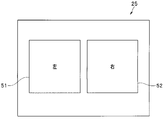
- FIG. 3 is a diagram illustrating an example of two types of optical images formed on the image sensor in the endoscope system according to the first embodiment.
- an endoscope system 1 includes an endoscope 2 that is a so-called 3D endoscope that includes an imaging element 25 and generates a stereoscopic image, and an endoscope. 2 is detachably connected to the processor 3 that performs predetermined signal processing, the endoscope 2 is detachably connected to the light source device 4 that supplies illumination light to the endoscope 2, and the processor 3 generates And a monitor 5 as a display device that displays the image signal as an endoscopic image.
- the endoscope 2 includes an elongated insertion portion 6 to be inserted into a body cavity, an operation portion 7 provided at the rear end of the insertion portion 6, and a universal cord 8 extending from the operation portion 7. .
- the universal cord 8 branches into a light guide cord 9 and a signal cord (signal cable) 10 near or at the base end thereof.
- the light source connector 11 at the end of the light guide cord 9 is detachably connected to the light source device 4, and the signal connector 12 at the end of the signal cord 10 is detachably connected to the processor 3.
- the signal connector 12 is provided with an ID memory 20 that is a storage unit for storing individual information for each endoscope 2, for example, individual information relating to the image sensor 25.
- a light guide 13 for transmitting illumination light is inserted through the insertion section 6, the operation section 7 and the universal cord 8. Then, by connecting the light source connector 11 to the light source device 4, the illumination light from the light source device 4 is transmitted by the light guide 13, and the light guide attached to the illumination window provided at the distal end portion 14 of the insertion portion 6. The transmitted illumination light is emitted from the tip surface 13a.
- a connector in which the light source connector 11 and the signal connector 12 are integrated is connected to the light source device 4, and the signal of the signal connector 12 is exchanged with the processor 3 through a cable connecting the light source device 4 and the processor 3. You may make it the structure to carry out.
- the distal end portion 14 is provided with an observation window (imaging window) adjacent to the illumination window, and the optical window of the illuminated subject such as an affected area enters the observation window with parallax.
- An objective lens 21 and a second objective lens 22 are disposed (see FIG. 2).
- Predetermined objective optical systems 23 and 24 are disposed behind the first objective lens 21 and the second objective lens 22, respectively.
- An imaging element 25 is disposed at the imaging positions of the first objective lens 21 and the second objective lens 22 through the objective optical systems 23 and 24.
- the endoscope 2 in the first embodiment inputs an optical image having parallax between the two first objective lens 21 and the second objective lens 22 as a 3D endoscope,
- Each of the objective optical systems 23 and 24 generates a first optical image and a second optical image which are separate optical images.
- An image is formed on the imaging surface.
- the image pickup element 25 is constituted by, for example, a CCD image sensor, and is connected to the processor 3 via the signal connector 12 after passing through the insertion portion 6 and the cable inserted into the universal cord 8.
- the image sensor 25 corresponds to the first optical image and the second optical image, which are different optical images, from each optical image on the same imaging surface of the CCD. An image is formed on a predetermined area.
- the first optical image for the left is formed in the first region 51
- the second optical image for the right is formed in the second region 52, respectively.
- the first area 51 and the second area 52 are illustrated as having a substantially rectangular shape. This is because the processor 3 performs predetermined imaging related to the first optical image and the second optical image. This is because the area corresponds to the area to be cut out.
- first region 51 and the second region 52 which are the respective image formation regions of the first optical image and the second optical image, are not limited to a rectangular shape, but may be, for example, a region exhibiting a circular shape. Also good. Further, the first region 51 and the second region 52 may be set so that some regions overlap each other.
- the two optical images are formed at any position (region) on the imaging surface of the imaging element 25.
- “Imaging position information” indicating whether or not the image is shipped is obtained in advance for each endoscope to be shipped, and the “imaging position information” is stored in the ID memory 20 provided in the signal connector 12. It has become.
- the positional information includes X ⁇ on the imaging surface of the first region 51 corresponding to the left first optical image and the second region 52 corresponding to the right second optical image as shown in FIG. Y coordinate information.
- the processor 3 includes a power supply circuit (not shown) that generates a plurality of power supply voltages necessary for the operation of the image sensor and the like, and a signal processing circuit (image processing unit) that performs predetermined signal processing on an image signal output from the image sensor 32, a preprocessing unit 33, etc.), a CCD drive circuit 34 that drives the image pickup device 25 in the endoscope 2, and a control unit that controls various circuits including the power supply circuit, the signal processing circuit, and the CCD drive circuit 34. 31.
- the control unit 31 controls various circuits in the processor 3 as described above, and stores the internal circuit stored in the ID memory 20 in the signal connector 12 when the endoscope 2 is connected to the processor 3.
- the “imaging position information” which is individual information of the endoscope 2 is obtained.
- the preprocessing unit 33 inputs an image pickup signal from the image pickup device 25 (in this embodiment, an image pickup signal related to the first optical image and the second optical image) and performs predetermined presignal processing.
- the control unit 31 includes a known signal amplification unit, process circuit, A / D converter, white balance circuit, and the like.
- the image processing unit 32 includes an image processing unit (not shown) that performs predetermined image processing on the output signal from the preprocessing unit 33, and the “imaging position” stored in the ID memory 20 under the control of the control unit 31.
- An imaging region cutout unit (not shown) that cuts out a predetermined imaging region of the first optical image and the second optical image based on “information”.
- the imaging region cutout unit is the individual information of the endoscope 2 connected to the processor 3, and the first optical image and the second optical image formed on the imaging surface of the imaging element 25.
- the first region 51 corresponding to the first optical image on the imaging surface and the second region 52 corresponding to the second optical image are cut out based on the “imaging position information” of the optical image. It is like that.
- the image processing unit 32 performs predetermined image processing in each of the two imaging regions (the first region 51 and the second region 52) cut out by the imaging region cutting unit, and displays two image signals for display (this embodiment). In FIG. 5, a left image signal related to the first region 51 and a right image signal related to the second region 52) are generated.
- the image processing unit 32 has a function of detecting white spots in the image sensor 25 and correcting the white spots based on the left image signal related to the first area 51 and the right image signal related to the second area 52. .
- FIG. 4 is a block diagram illustrating a configuration of a functional unit that detects and corrects white scratches in the image processing unit of the endoscope system according to the first embodiment.
- the image processing unit 32 adjusts the parallax value between the left image signal and the right image signal, which are two image signals having different optical characteristics (that is, having parallax in this embodiment).
- a white-scratch detection unit 63 that detects the white-scratch
- a white-scratch correction unit 64 that performs a predetermined correction on a pixel in which the white-scratch occurs based on the detection result of the white-scratch detection unit 63
- the parallax adjustment unit 61 stores the “parallax information” stored in the ID memory 20 in the endoscope 2 connected to the processor 3 under the control of the control unit 31, and based on the parallax information, The parallax between the left image signal related to the first region 51 and the right image signal related to the second region 52 having parallax is adjusted to be substantially zero.
- the viewing direction related to the left image signal is shifted by the amount of parallax so as to match the viewing direction related to the right image signal, and the parallax is adjusted to be substantially zero.
- the comparison unit 62 controls the brightness value of each pixel in the left image signal related to the first region 51 in which the parallax is substantially adjusted to zero by the parallax adjustment unit 61 under the control of the control unit 31, and the second The luminance value of each pixel in the right image signal relating to the region 52 is compared with the luminance value for each pixel.
- the white spot detection unit 63 is controlled on the image sensor 25 based on a comparison result of luminance values for each pixel in the first region 51 and the second region 52 compared in the comparison unit 62 under the control of the control unit 31. The presence or absence of white scratches is detected.
- the luminance value of the pixel 71 in the first area 51 is larger than the corresponding pixel in the second area 52 by a predetermined value or more.
- the white spot detection unit 63 determines that a white spot has occurred in the portion of the pixel 71.
- the white spot detection unit 63 determines whether the pixel 72 and the pixel 73 It is determined that white scratches have occurred on the part.
- the white defect correction unit 64 Based on the detection result of the white defect detection unit 63, the white defect correction unit 64 performs a predetermined correction on the pixel in which the white defect has occurred, and in the above case, the pixels 71, 72, and 73 to correct the white defect. It is designed to reduce the impact.
- the output signal related to the pixel 71 in the first area 51 in which white scratches have occurred is replaced and corrected with the output signal related to the corresponding pixel 71 a in the second area 52.
- the output signal related to the pixel 72 in the second area 52 in which white scratches have occurred is replaced with the output signal related to the corresponding pixel 72 a in the first area 51 for correction.
- correction may be performed so as to complement based on surrounding information, such as a pixel 73 in which white scratches have occurred.
- the image processing unit 32 includes a combining unit 65 that performs predetermined 3D combining processing on the left image signal and the right image signal in which the white defect has been corrected by the white defect correction unit 64 and outputs the result.
- One video signal subjected to the 3D synthesis processing in the synthesis unit 65 is output to the monitor 5.
- the image processing unit 32 performs predetermined 3D synthesis processing on the imaging signals corresponding to the two imaging regions, and outputs the image signal to a normal monitor as one video signal.
- the present invention is not limited to this, and a so-called 3D-compatible monitor device is adopted as the monitor 5, and the known 3D processing is appropriately performed and displayed on the two video signals with parallax without performing the above-described combining processing. You may make it do.
- the two optical images are formed at any position (region) on the imaging surface of the imaging element 25.
- the “imaging position information” is acquired in advance by inspection for each endoscope to be shipped, and the “imaging position information” is stored in the ID memory 20 provided in the signal connector 12.
- control unit 31 obtains the “imaging position information” and the “parallax information” stored in the ID memory 20. To do.
- the preprocessing unit 33 inputs an imaging signal from the imaging device 25 and performs predetermined preprocessing, and then the image processing unit 32 extracts the imaging region.
- the unit cuts out a predetermined imaging region of the first optical image and the second optical image based on the “imaging position information”.
- the image processing unit 32 performs predetermined image processing on each of the two imaging regions cut out by the imaging region cutting unit to generate a left image signal related to the first region 51 and a right image signal related to the second region 52. To do.
- the parallax adjustment unit 61 in the image processing unit 32 stores the “parallax information” stored in the ID memory 20 in the endoscope 2 under the control of the control unit 31, and based on the parallax information, The parallax between the left image signal related to the first area 51 and the right image signal related to the second area 52 is adjusted to be substantially zero.
- the comparison unit 62 controls the luminance value of each pixel in the left image signal related to the first region 51 in which the parallax is substantially adjusted to zero by the parallax adjustment unit 61, and the second region.
- the luminance value of each pixel in the right image signal according to 52 is compared with the luminance value for each pixel.
- the white spot detection unit 63 is based on the comparison result of the luminance values for each pixel in the first region 51 and the second region 52 compared in the comparison unit 62. Detect the presence of white scratches on the top.
- the white spot correction unit 64 performs a predetermined correction on the pixel in which the white spot is generated, and affects the white spot. Reduce.
- the image processing unit 32 monitors the video signal synthesized by performing a predetermined 3D synthesis process on the left image signal and the right image signal whose white defect has been corrected by the white defect correction unit 64 in the synthesis unit 65. Output to.
- the endoscope system of the first embodiment in the imaging system that generates a new display image using two types of images with parallax, white scratch pixels are accurately detected.
- An imaging system capable of correction can be provided.
- the endoscope system according to the first embodiment includes an 3D endoscope that forms two optical images having parallax as two types of optical images on one image sensor.
- the present invention is applied to a system.
- the endoscope system according to the second embodiment has two optical images generated by separating one incident optical image into one optical image.
- An endoscope system including an endoscope that forms an image on an image sensor.
- the endoscope system forms two separated optical images on the image pickup surface of one image pickup device, and two different brightnesses with respect to the two optical images.
- a high dynamic range image is obtained by generating an imaging signal and converting the two imaging signals into an image signal and combining them.
- FIG. 7 is a diagram showing a configuration of an endoscope system according to the second embodiment of the present invention
- FIG. 8 is a configuration of an optical member disposed at the distal end portion of the insertion portion in the endoscope system according to the second embodiment
- FIG. 9 is a diagram illustrating an example of two types of optical images formed on the image sensor in the endoscope system according to the second embodiment.
- the basic configuration of the endoscope system 101 of the second embodiment is the same as that of the first embodiment, but the distal end portion of the insertion portion in the endoscope 102 as compared to the first embodiment.
- the configuration of 114 is different.
- the two first objective lens 21 and the second objective lens 22 that are incident on each other with parallax are provided.
- An objective lens 121 for receiving an optical image of a subject such as an affected part is disposed at the distal end portion 114.
- An optical prism 123 is disposed behind the objective lens 121. As shown in FIG. 8, the optical prism 123 divides the one optical image from the objective lens 121 into a first optical image and a second optical image and emits the light toward the image sensor 125. An image dividing unit. An imaging element 125 is disposed at the imaging position of the first optical image and the second optical image output from the optical prism 123 as two optical paths (first optical path and second optical path). .
- a mirror 124b and means for reducing light for example, an ND filter 124a, are provided on the first optical path related to the first optical image among the two optical images output from the optical prism 123. It is arranged.
- the first optical image reflected by the prism surface is folded back by the mirror 124b and incident on the optical prism 123 again, and the luminance is actively reduced by the ND filter 124a.
- the image is formed on the image sensor 125.
- the first optical image formed on the image sensor 125 is an image having a relatively low brightness as compared with the second optical image.
- the first optical image and the second optical image divided from the one optical image by the optical prism 123 are formed on the imaging surface of the imaging element 125, respectively.
- the optical image 1 is formed as an image with reduced brightness by the light reducing means.
- the image sensor 125 corresponds to each optical image on the same imaging surface of the CCD, the first optical image and the second optical image, which are two types of optical images. An image is formed in a predetermined area.
- the low-luminance first optical image is formed in the region 151
- the high-luminance second optical image is formed in the region 152.
- the position of the two optical images on the imaging surface of the imaging element 125 (The “imaging position information” indicating whether or not the image is formed in the region) is obtained in advance by inspection for each endoscope to be shipped, and the “imaging position information” is provided in the signal connector 12. It is stored in the memory 20.
- luminance difference information between the low-luminance first optical image and the high-luminance second optical image is stored in the ID memory 20. It has become.
- the processor 103 includes a power supply circuit (not shown) that generates power supplies of a plurality of power supply voltages necessary for the operation of the image sensor and the like, and predetermined signal processing for an image signal output from the image sensor.
- a signal processing circuit an image processing unit 132, a preprocessing unit 33, etc.
- a CCD driving circuit 34 for driving the imaging device 25 in the endoscope 2
- the power supply circuit the signal processing circuit and the CCD driving circuit 34.
- a control unit 31 that controls various circuits including the control unit 31.
- control unit 31 controls various circuits in the processor 103 as described above, and when the endoscope 102 is connected to the processor 103, the signal connector 12
- the “imaging position information” and the “luminance difference information” which are individual information of the endoscope 102 stored in the ID memory 20 are obtained.
- the image processing unit 132 includes an image processing unit (not shown) that performs predetermined image processing on an output signal from the preprocessing unit 33, and a control unit. Under the control of 31, based on the “imaging position information” stored in the ID memory 20, a predetermined imaging area of the first optical image and the second optical image is cut out. And an exit.
- the image processing unit 132 performs predetermined image processing on each of the two imaging regions (the region 151 and the region 152) cut out by the imaging region cutting unit, and outputs two display image signals (in this embodiment, regions 151, and a high-luminance image signal according to the region 152).
- the image processing unit 132 has a function of detecting white spots in the image sensor 125 and correcting the white spots based on the low brightness image signal related to the area 151 and the high brightness image signal related to the area 152.
- FIG. 10 is a block diagram illustrating a configuration of a functional unit that detects and corrects white scratches in the image processing unit of the endoscope system according to the second embodiment.
- the image processing unit 132 calculates a difference in luminance value between the low luminance image signal and the high luminance image signal, which are two image signals having different optical characteristics (in this embodiment, different luminance values).
- the comparison unit 162 that compares the luminance values of the low luminance image signal and the high luminance image signal adjusted by the luminance difference adjustment unit 161, and the information that is compared in the comparison unit 162
- a white spot detection unit 163 that detects a white spot on the image sensor 125, and a white spot correction unit 164 that performs predetermined correction on a pixel in which the white spot has occurred based on a detection result in the white spot detection unit 163.
- the luminance difference adjustment unit 161 stores the “luminance difference information” stored in the ID memory 20 in the endoscope 2 connected to the processor 3 under the control of the control unit 31, and the luminance difference information is stored in the luminance difference information. Based on this, the brightness difference between the low brightness image signal related to the region 151 and the high brightness image signal related to the region 152 having different brightness values is adjusted to be substantially zero.
- the gain related to the low-luminance image signal is adjusted and adjusted so that the luminance difference is substantially zero according to the luminance value of the high-luminance image signal.
- the comparison unit 162 controls the luminance value of each pixel in the low luminance image signal related to the region 151 in which the luminance difference is substantially adjusted to zero by the luminance difference adjustment unit 161 under the control of the control unit 31, and the region.
- the luminance value of each pixel in the high luminance image signal 152 is compared with the luminance value for each pixel.
- the white spot detection unit 163 determines whether or not there is a white spot on the image sensor 125 based on the comparison result of the luminance value for each pixel in the region 151 and the region 152 compared in the comparison unit 162. Is supposed to be detected. Since the method for detecting the presence or absence of white scratches is the same as in the first embodiment, a detailed description thereof is omitted here.
- the white defect correction unit 164 performs predetermined correction on the pixel in which the white defect has occurred, based on the detection result in the white defect detection unit 163, so that the white defect is corrected. It is designed to reduce the impact. Since this white defect correction method is also the same as that of the first embodiment, a detailed description thereof is omitted here.
- the image processing unit 132 includes a combining unit 615 that performs predetermined 3D combining processing on the low-intensity image signal and the high-intensity image signal in which the white defect is corrected by the white defect correction unit 164 and outputs the resultant signal. Then, one video signal subjected to the 3D synthesis process in the synthesis unit 165 is output to the monitor 5.
- the two optical images are located at any position (region) on the imaging surface of the imaging element 125.
- “Image formation position information” indicating whether or not an image has been formed is acquired in advance for each endoscope to be shipped, and the “image formation position information” is stored in the ID memory 20 provided in the signal connector 12.
- the “brightness difference information” between the low-luminance first optical image and the high-luminance second optical image in the endoscope 102. Is stored in the ID memory 20.
- the control unit 31 stores the “imaging position information” and the “luminance difference information” stored in the ID memory 20. Obtain.
- the preprocessing unit 33 inputs an imaging signal from the imaging device 125 and performs predetermined preprocessing, and then the imaging region extraction in the image processing unit 132 is performed.
- the unit cuts out a predetermined imaging region of the first optical image and the second optical image based on the “imaging position information”.
- the image processing unit 132 performs predetermined image processing on each of the two imaging regions cut out by the imaging region cutting unit, and generates a low luminance image signal related to the region 151 and a high luminance image signal related to the region 152.
- the luminance difference adjustment unit 161 in the image processing unit 132 stores the “luminance difference information” stored in the ID memory 20 in the endoscope 102 under the control of the control unit 31, and based on the luminance difference information.
- the brightness difference between the low brightness image signal related to the area 151 and the high brightness image signal related to the area 152 is adjusted to be substantially zero.
- the comparison unit 162 controls the luminance value of each pixel in the low luminance image signal related to the region 151 in which the luminance difference is adjusted to substantially zero by the luminance difference adjustment unit 161, and the region 152.
- the luminance value of each pixel in the high luminance image signal according to the above is compared for each pixel.
- the white spot detection unit 163 performs the white spot on the image sensor 125 based on the comparison result of the luminance value for each pixel in the region 151 and the region 152 compared in the comparison unit 162. The presence or absence of is detected.
- the white spot correction unit 164 performs a predetermined correction on the pixel in which the white spot is generated, and affects the white spot. Reduce.
- the image processing unit 132 performs a predetermined 3D synthesis process on the low-luminance image signal and the high-luminance image signal in which the white defect has been corrected by the white defect correction unit 164 in the synthesis unit 165, and the synthesized video signal. Output to the monitor 5.
- the endoscope system of the second embodiment in the imaging system that generates a new display image using two types of images having different luminance values, white-scratched pixels are accurately detected.
- An imaging system capable of detecting and correcting can be provided.
- the present invention is not limited to an endoscope system having an endoscope equipped with a solid-state imaging device as in the first embodiment and the second embodiment, and a new display image is generated using two types of images.
- the present invention can be applied to an imaging system including a solid-state imaging device that can generate and detect white scratched pixels.
Abstract
Description
図1から図3を用いて第1の実施形態の内視鏡システムの構成について説明する。図1は、本発明の第1の実施形態の内視鏡システムの構成を示す図、図2は、第1の実施形態の内視鏡システムにおける挿入部先端部の構成を示す斜視図、図3は、第1の実施形態の内視鏡システムにおける撮像素子に結像される2種の光学像の一例を示した図である。 (First embodiment)
The configuration of the endoscope system according to the first embodiment will be described with reference to FIGS. 1 to 3. FIG. 1 is a diagram illustrating a configuration of an endoscope system according to a first embodiment of the present invention. FIG. 2 is a perspective view illustrating a configuration of a distal end portion of an insertion portion in the endoscope system according to the first embodiment. FIG. 3 is a diagram illustrating an example of two types of optical images formed on the image sensor in the endoscope system according to the first embodiment.
また、画像処理部32は、前記第1領域51に係る左側画像信号および第2領域52に係る右側画像信号に基づいて撮像素子25における白傷の検出および当該白傷の補正を行う機能を備える。 <White Scratch Detection and Correction Function in First Embodiment>
Further, the
次に、本発明の第2の実施形態について説明する。 (Second Embodiment)
Next, a second embodiment of the present invention will be described.
また、画像処理部132は、前記領域151に係る低輝度像信号および領域152に係る高輝度画像信号に基づいて撮像素子125における白傷の検出および当該白傷の補正を行う機能を備える。 <White Scratch Detection and Correction Function in Second Embodiment>
Further, the
Claims (4)
- 被写体の光学像を撮像する撮像素子と、
前記被写体の第1の光学像と、当該第1の光学像と光学特性の異なる前記被写体の第2の光学像を生成し、前記撮像素子上の所定の位置に結像させる光学系と、
前記撮像素子上に結像された前記第1の光学像と前記第2の光学像を光電変換し、それぞれ第1の撮像信号と第2の撮像信号として出力する撮像信号生成部と、
前記第1の光学像に係る第1光学特性と前記第2の光学像に係る第2光学特性とにおける光学特性の差を調整する調整部と、
前記調整部により光学特性の差が調整された前記第1光学特性と前記第2光学特性とに基づいて、前記第1の撮像信号と前記第2の撮像信号における前記被写体の対応する領域を表す一対の画素の輝度値を比較する輝度値比較部と、
前記輝度値比較部の比較結果に基づいて、輝度値の差分が所定値以上となる前記一対の画素に対して、輝度値が大きい方の画素を輝度過剰画素として検出する輝度過剰画素検出部と、
前記輝度過剰画素検出部により検出された前記輝度過剰画素に対して、前記輝度値の差分が前記所定値以下となるよう補正処理を施す補正処理部と、
前記補正処理部により補正処理を施された、前記第1の撮像信号が表す第1の画像信号と前記第2の撮像信号が表す第2の画像信号を合成して出力する信号合成部と、
を備えたことを特徴とする撮像システム。 An image sensor that captures an optical image of a subject;
An optical system that generates a first optical image of the subject and a second optical image of the subject having different optical characteristics from the first optical image, and forms an image at a predetermined position on the image sensor;
An imaging signal generation unit that photoelectrically converts the first optical image and the second optical image formed on the imaging element and outputs them as a first imaging signal and a second imaging signal, respectively;
An adjustment unit that adjusts a difference in optical characteristics between the first optical characteristic related to the first optical image and the second optical characteristic related to the second optical image;
Based on the first optical characteristic and the second optical characteristic whose optical characteristic difference has been adjusted by the adjustment unit, a corresponding region of the subject in the first imaging signal and the second imaging signal is represented. A luminance value comparison unit for comparing luminance values of a pair of pixels;
Based on the comparison result of the luminance value comparison unit, an excessive luminance pixel detection unit that detects a pixel having a larger luminance value as an excessive luminance pixel with respect to the pair of pixels whose luminance value difference is equal to or greater than a predetermined value; ,
A correction processing unit that performs a correction process on the excessive luminance pixel detected by the excessive luminance pixel detection unit so that a difference between the luminance values is equal to or less than the predetermined value;
A signal combining unit that combines the first image signal represented by the first imaging signal and the second image signal represented by the second imaging signal that have been subjected to correction processing by the correction processing unit;
An imaging system comprising: - 前記第1の光学像に係る前記第1光学特性と前記第2の光学像に係る前記第2光学特性とにおける前記光学特性の差は、前記第1の光学像と前記第2の光学像間の視差であり、
前記一対の画素は、前記第1の撮像信号における第1の画素と、前記第2の撮像信号において、前記第1の画素上に撮像された前記被写体の領域に対応する領域が撮像される第2の画素と、で構成され、
前記光学系は、前記第1の光学像と、当該第1の光学像と視差を有する前記第2の光学像を生成し、
前記輝度値比較部は、前記撮像信号生成部により生成された前記第2の撮像信号において、前記第1の画素に対応する画素位置から前記視差分ずらした画素位置に位置する画素を、前記第2の画素として設定する画素位置設定部を備え、
前記第1の画素と、前記画素位置設定部により設定された前記第2の画素と、からなる前記一対の画素の輝度値を比較することを特徴とする請求項1に記載の撮像システム。 The difference between the first optical characteristic relating to the first optical image and the second optical characteristic relating to the second optical image is the difference between the first optical image and the second optical image. The parallax of
In the pair of pixels, a first pixel in the first imaging signal and a region corresponding to the region of the subject imaged on the first pixel in the second imaging signal are imaged. 2 pixels,
The optical system generates the first optical image and the second optical image having a parallax with the first optical image;
The luminance value comparison unit includes, in the second imaging signal generated by the imaging signal generation unit, a pixel located at a pixel position shifted by the parallax from a pixel position corresponding to the first pixel. A pixel position setting unit for setting as two pixels,
2. The imaging system according to claim 1, wherein brightness values of the pair of pixels including the first pixel and the second pixel set by the pixel position setting unit are compared. - 前記第1の光学像に係る前記第1光学特性と前記第2の光学像に係る前記第2光学特性とにおける前記光学特性の差は、前記第1の光学像と前記第2の光学像との明るさの差であり、
前記一対の画素は、前記第1の撮像信号における第1の画素と、前記第2の撮像信号において、前記第1の画素上に撮像された前記被写体の領域に対応する領域が撮像される第2の画素で構成され、
前記光学系は、前記第2の光学像の明るさを減光する減光部材を備え、
前記輝度値比較部は、前記第2の画素に対して、前記減光部材による前記第2の光学像の明るさの減光量に基づいて、前記減光部材により減光される以前の前記第2の光学像の明るさに応じた比較用輝度値を算出する比較用輝度値算出部を備え、
前記第1の画素の輝度値と、前記第2の画素における前記比較用輝度値算出部により算出された前記比較用輝度値と、からなる前記一対の画素の輝度値を比較することを特徴とする請求項1に記載の撮像システム。 The difference in the optical characteristics between the first optical characteristic related to the first optical image and the second optical characteristic related to the second optical image is the difference between the first optical image and the second optical image. Is the difference in brightness
In the pair of pixels, a first pixel in the first imaging signal and a region corresponding to the region of the subject imaged on the first pixel in the second imaging signal are imaged. 2 pixels,
The optical system includes a dimming member for dimming the brightness of the second optical image,
The brightness value comparison unit is configured to reduce the second pixel before the light is reduced by the light reducing member based on the light amount of the brightness of the second optical image by the light reducing member. A comparative luminance value calculation unit for calculating a comparative luminance value according to the brightness of the optical image of 2,
Comparing a luminance value of the pair of pixels including the luminance value of the first pixel and the comparison luminance value calculated by the comparison luminance value calculation unit in the second pixel; The imaging system according to claim 1. - 前記撮像部と、前記光学系と、前記撮像信号生成部と、を具備する内視鏡と、
前記輝度値比較部と、前記輝度過剰画素情報検出部と、前記補正処理部と、前記信号合成部と、を具備するプロセッサと、
を備え、
前記内視鏡は、前記第1の光学像と前記第2の光学像の光学特性を予め格納させておく記憶部をさらに備えることを特徴とする請求項1から3のいずれか一項に記載の撮像システム。 An endoscope comprising the imaging unit, the optical system, and the imaging signal generation unit;
A processor comprising the luminance value comparison unit, the excessive luminance pixel information detection unit, the correction processing unit, and the signal synthesis unit;
With
4. The endoscope according to claim 1, further comprising a storage unit that stores in advance optical characteristics of the first optical image and the second optical image. 5. Imaging system.
Priority Applications (4)
| Application Number | Priority Date | Filing Date | Title |
|---|---|---|---|
| CN201580033789.3A CN106664381A (en) | 2014-10-14 | 2015-10-02 | Image capturing system |
| EP15851024.8A EP3145176A4 (en) | 2014-10-14 | 2015-10-02 | Image capturing system |
| JP2016522076A JP6017735B2 (en) | 2014-10-14 | 2015-10-02 | Imaging system |
| US15/378,145 US10206554B2 (en) | 2014-10-14 | 2016-12-14 | Image pickup system with white spot correction |
Applications Claiming Priority (2)
| Application Number | Priority Date | Filing Date | Title |
|---|---|---|---|
| JP2014210281 | 2014-10-14 | ||
| JP2014-210281 | 2014-10-14 |
Related Child Applications (1)
| Application Number | Title | Priority Date | Filing Date |
|---|---|---|---|
| US15/378,145 Continuation US10206554B2 (en) | 2014-10-14 | 2016-12-14 | Image pickup system with white spot correction |
Publications (1)
| Publication Number | Publication Date |
|---|---|
| WO2016059983A1 true WO2016059983A1 (en) | 2016-04-21 |
Family
ID=55746531
Family Applications (1)
| Application Number | Title | Priority Date | Filing Date |
|---|---|---|---|
| PCT/JP2015/078091 WO2016059983A1 (en) | 2014-10-14 | 2015-10-02 | Image capturing system |
Country Status (5)
| Country | Link |
|---|---|
| US (1) | US10206554B2 (en) |
| EP (1) | EP3145176A4 (en) |
| JP (1) | JP6017735B2 (en) |
| CN (1) | CN106664381A (en) |
| WO (1) | WO2016059983A1 (en) |
Cited By (6)
| Publication number | Priority date | Publication date | Assignee | Title |
|---|---|---|---|---|
| WO2018154661A1 (en) * | 2017-02-22 | 2018-08-30 | オリンパス株式会社 | Image processing device for endoscope and endoscope system |
| WO2018225377A1 (en) * | 2017-06-07 | 2018-12-13 | オリンパス株式会社 | Endoscopic imaging system |
| CN109475266A (en) * | 2016-07-11 | 2019-03-15 | 奥林巴斯株式会社 | Endoscope apparatus |
| WO2019123710A1 (en) * | 2017-12-22 | 2019-06-27 | オリンパス株式会社 | Endoscope inspection device and endoscope inspection system |
| WO2020084784A1 (en) * | 2018-10-26 | 2020-04-30 | オリンパス株式会社 | Image processing device and endoscope system |
| WO2021176717A1 (en) * | 2020-03-06 | 2021-09-10 | オリンパス株式会社 | Endoscope device, processor for endoscopic image, and method for generating endoscopic image |
Families Citing this family (2)
| Publication number | Priority date | Publication date | Assignee | Title |
|---|---|---|---|---|
| CN107405048B (en) * | 2015-05-14 | 2019-07-02 | 奥林巴斯株式会社 | Stereopsis endoscope apparatus |
| EP3417763A1 (en) * | 2017-06-22 | 2018-12-26 | Helmholtz Zentrum München - Deutsches Forschungszentrum für Gesundheit und Umwelt (GmbH) | System for endoscopic imaging |
Citations (5)
| Publication number | Priority date | Publication date | Assignee | Title |
|---|---|---|---|---|
| JPH11355650A (en) * | 1998-06-09 | 1999-12-24 | Nikon Corp | Image fetching device |
| JP2004313523A (en) * | 2003-04-17 | 2004-11-11 | Pentax Corp | Solid-state image sensor, electronic endoscope |
| JP2005311983A (en) * | 2004-04-26 | 2005-11-04 | Olympus Corp | Image processing apparatus |
| JP2006086839A (en) * | 2004-09-16 | 2006-03-30 | Canon Inc | Defective pixel correction device |
| JP2014007599A (en) * | 2012-06-25 | 2014-01-16 | Sharp Corp | Image pick-up device, defect processing method, defect processing program and electronic information apparatus |
Family Cites Families (20)
| Publication number | Priority date | Publication date | Assignee | Title |
|---|---|---|---|---|
| JP3785520B2 (en) | 1997-03-19 | 2006-06-14 | コニカミノルタホールディングス株式会社 | Electronic camera |
| US6529640B1 (en) * | 1998-06-09 | 2003-03-04 | Nikon Corporation | Image processing apparatus |
| JP3587506B2 (en) * | 1999-08-30 | 2004-11-10 | 富士重工業株式会社 | Stereo camera adjustment device |
| JP2001086411A (en) | 1999-09-13 | 2001-03-30 | Matsushita Electric Ind Co Ltd | Solid-state image pickup device |
| JP2001148865A (en) | 1999-11-19 | 2001-05-29 | Minolta Co Ltd | Image input device |
| JP2003032559A (en) | 2001-07-17 | 2003-01-31 | Victor Co Of Japan Ltd | Imaging apparatus |
| JP2008164367A (en) * | 2006-12-27 | 2008-07-17 | Matsushita Electric Ind Co Ltd | Solid body imaging device, camera, vehicle and surveillance device |
| JP5246851B2 (en) | 2008-03-24 | 2013-07-24 | 株式会社日立国際電気 | Pixel defect correction method and television camera |
| US8908058B2 (en) * | 2009-04-18 | 2014-12-09 | Lytro, Inc. | Storage and transmission of pictures including multiple frames |
| WO2012017735A1 (en) * | 2010-08-02 | 2012-02-09 | オリンパスメディカルシステムズ株式会社 | Endoscope system |
| JP2012065204A (en) | 2010-09-16 | 2012-03-29 | Toshiba Corp | Compound-eye imaging device, signal processing device, control method for compound-eye imaging device |
| JP2012134875A (en) * | 2010-12-22 | 2012-07-12 | Olympus Corp | Endoscope device |
| EP2538242B1 (en) * | 2011-06-24 | 2014-07-02 | Softkinetic Software | Depth measurement quality enhancement. |
| JP5824953B2 (en) * | 2011-08-09 | 2015-12-02 | 株式会社ソシオネクスト | Image processing apparatus, image processing method, and imaging apparatus |
| US9560334B2 (en) * | 2011-09-08 | 2017-01-31 | Qualcomm Incorporated | Methods and apparatus for improved cropping of a stereoscopic image pair |
| US9100635B2 (en) * | 2012-06-28 | 2015-08-04 | Pelican Imaging Corporation | Systems and methods for detecting defective camera arrays and optic arrays |
| EP2750391B1 (en) * | 2012-12-31 | 2017-03-22 | Nokia Technologies Oy | Method, apparatus and computer program product for processing of images |
| WO2014164550A2 (en) * | 2013-03-13 | 2014-10-09 | Pelican Imaging Corporation | System and methods for calibration of an array camera |
| EP3232900A1 (en) * | 2014-12-19 | 2017-10-25 | Boston Scientific Scimed Inc. | Calibrated medical imaging devices and related methods |
| KR102346961B1 (en) * | 2015-03-18 | 2022-01-04 | 삼성전자주식회사 | Image Process Device and Denoising System Having the Same |
-
2015
- 2015-10-02 JP JP2016522076A patent/JP6017735B2/en active Active
- 2015-10-02 CN CN201580033789.3A patent/CN106664381A/en active Pending
- 2015-10-02 WO PCT/JP2015/078091 patent/WO2016059983A1/en active Application Filing
- 2015-10-02 EP EP15851024.8A patent/EP3145176A4/en not_active Withdrawn
-
2016
- 2016-12-14 US US15/378,145 patent/US10206554B2/en active Active
Patent Citations (5)
| Publication number | Priority date | Publication date | Assignee | Title |
|---|---|---|---|---|
| JPH11355650A (en) * | 1998-06-09 | 1999-12-24 | Nikon Corp | Image fetching device |
| JP2004313523A (en) * | 2003-04-17 | 2004-11-11 | Pentax Corp | Solid-state image sensor, electronic endoscope |
| JP2005311983A (en) * | 2004-04-26 | 2005-11-04 | Olympus Corp | Image processing apparatus |
| JP2006086839A (en) * | 2004-09-16 | 2006-03-30 | Canon Inc | Defective pixel correction device |
| JP2014007599A (en) * | 2012-06-25 | 2014-01-16 | Sharp Corp | Image pick-up device, defect processing method, defect processing program and electronic information apparatus |
Non-Patent Citations (1)
| Title |
|---|
| See also references of EP3145176A4 * |
Cited By (13)
| Publication number | Priority date | Publication date | Assignee | Title |
|---|---|---|---|---|
| CN109475266A (en) * | 2016-07-11 | 2019-03-15 | 奥林巴斯株式会社 | Endoscope apparatus |
| CN109475266B (en) * | 2016-07-11 | 2021-08-10 | 奥林巴斯株式会社 | Endoscope device |
| US11045071B2 (en) | 2017-02-22 | 2021-06-29 | Olympus Corporation | Image processing apparatus for endoscope and endoscope system |
| WO2018154661A1 (en) * | 2017-02-22 | 2018-08-30 | オリンパス株式会社 | Image processing device for endoscope and endoscope system |
| WO2018225377A1 (en) * | 2017-06-07 | 2018-12-13 | オリンパス株式会社 | Endoscopic imaging system |
| JP6463573B1 (en) * | 2017-06-07 | 2019-02-06 | オリンパス株式会社 | Endoscopic imaging system |
| US11375882B2 (en) | 2017-06-07 | 2022-07-05 | Olympus Corporation | Endoscope system which generates an image of high dynamic range |
| CN111491548A (en) * | 2017-12-22 | 2020-08-04 | 奥林巴斯株式会社 | Endoscope inspection device and endoscope inspection system |
| JPWO2019123710A1 (en) * | 2017-12-22 | 2020-12-03 | オリンパス株式会社 | Endoscopy inspection system, endoscopy inspection equipment, endoscopy packaging, endoscopy method |
| US11089294B2 (en) | 2017-12-22 | 2021-08-10 | Olympus Corporation | Endoscope inspection system, endoscope inspection apparatus, endoscope package, and endoscope inspection method |
| WO2019123710A1 (en) * | 2017-12-22 | 2019-06-27 | オリンパス株式会社 | Endoscope inspection device and endoscope inspection system |
| WO2020084784A1 (en) * | 2018-10-26 | 2020-04-30 | オリンパス株式会社 | Image processing device and endoscope system |
| WO2021176717A1 (en) * | 2020-03-06 | 2021-09-10 | オリンパス株式会社 | Endoscope device, processor for endoscopic image, and method for generating endoscopic image |
Also Published As
| Publication number | Publication date |
|---|---|
| US10206554B2 (en) | 2019-02-19 |
| EP3145176A1 (en) | 2017-03-22 |
| EP3145176A4 (en) | 2018-04-18 |
| JPWO2016059983A1 (en) | 2017-04-27 |
| US20170086649A1 (en) | 2017-03-30 |
| JP6017735B2 (en) | 2016-11-02 |
| CN106664381A (en) | 2017-05-10 |
Similar Documents
| Publication | Publication Date | Title |
|---|---|---|
| JP6017735B2 (en) | Imaging system | |
| US9763558B2 (en) | Endoscope apparatus, method for operating endoscope apparatus, and information storage device | |
| US10523911B2 (en) | Image pickup system | |
| JP7289653B2 (en) | Control device, endoscope imaging device, control method, program and endoscope system | |
| JP5860663B2 (en) | Stereo imaging device | |
| JP2010073009A (en) | Image processing apparatus | |
| JPWO2016080130A1 (en) | Observation device | |
| US20190281220A1 (en) | Image pickup element, image pickup method, and electronic device | |
| JP5244164B2 (en) | Endoscope device | |
| SE1130099A1 (en) | Procedure for Gain Folder Generation in an IR Camera, and IR Camera for Performing Gain Folder Generation | |
| US10390688B2 (en) | Image pickup system | |
| JP2019080623A (en) | Endoscope apparatus | |
| JP5855795B2 (en) | Endoscope device | |
| US9826169B2 (en) | Image pickup apparatus, image processing apparatus, and method for activating image pickup apparatus | |
| JP6027793B2 (en) | Endoscope device | |
| WO2016098736A1 (en) | Image capturing system | |
| US10559072B2 (en) | Image detection device and image detection system | |
| US20200037865A1 (en) | Image processing device, image processing system, and image processing method | |
| JP2018023612A (en) | Endoscope system | |
| JP2013179580A (en) | Imaging apparatus | |
| JP2012134875A (en) | Endoscope device | |
| JP2016063391A (en) | Imaging device, display device, and electronic apparatus | |
| US20210290037A1 (en) | Medical image processing apparatus and medical observation system | |
| WO2016035366A1 (en) | Imaging system | |
| JP2019154628A (en) | Endoscope, endoscope system, and temperature detection method and program |
Legal Events
| Date | Code | Title | Description |
|---|---|---|---|
| ENP | Entry into the national phase |
Ref document number: 2016522076 Country of ref document: JP Kind code of ref document: A |
|
| 121 | Ep: the epo has been informed by wipo that ep was designated in this application |
Ref document number: 15851024 Country of ref document: EP Kind code of ref document: A1 |
|
| REEP | Request for entry into the european phase |
Ref document number: 2015851024 Country of ref document: EP |
|
| WWE | Wipo information: entry into national phase |
Ref document number: 2015851024 Country of ref document: EP |
|
| NENP | Non-entry into the national phase |
Ref country code: DE |