WO2016051980A1 - 電磁界解析装置、その表示装置、およびこれらを用いた計算システム - Google Patents
電磁界解析装置、その表示装置、およびこれらを用いた計算システム Download PDFInfo
- Publication number
- WO2016051980A1 WO2016051980A1 PCT/JP2015/073173 JP2015073173W WO2016051980A1 WO 2016051980 A1 WO2016051980 A1 WO 2016051980A1 JP 2015073173 W JP2015073173 W JP 2015073173W WO 2016051980 A1 WO2016051980 A1 WO 2016051980A1
- Authority
- WO
- WIPO (PCT)
- Prior art keywords
- electromagnetic field
- torque
- calculated
- field analysis
- calculation
- Prior art date
- Legal status (The legal status is an assumption and is not a legal conclusion. Google has not performed a legal analysis and makes no representation as to the accuracy of the status listed.)
- Ceased
Links
Images


Classifications
-
- G—PHYSICS
- G06—COMPUTING OR CALCULATING; COUNTING
- G06F—ELECTRIC DIGITAL DATA PROCESSING
- G06F30/00—Computer-aided design [CAD]
- G06F30/10—Geometric CAD
-
- G—PHYSICS
- G06—COMPUTING OR CALCULATING; COUNTING
- G06F—ELECTRIC DIGITAL DATA PROCESSING
- G06F30/00—Computer-aided design [CAD]
Definitions
- the present invention relates to an electromagnetic field analysis device, a display device thereof, and a calculation system using them.
- the following technologies are disclosed as a method for calculating electromagnetic force and torque using electromagnetic field analysis.
- Patent Document 1 when performing a coupled analysis between an electromagnetic field and a structure by a finite element method, an electromagnetic field analysis is performed using a first mesh suitable for electromagnetic field analysis, and each node included in the first mesh or Using the value of the electromagnetic field at each element side, the electromagnetic field at each node or each element side included in the second mesh suitable for structural analysis is calculated, and is included in the second mesh from the calculated electromagnetic field.
- a method is shown in which a nodal force, which is an expression of an electromagnetic force at each node, is calculated and a structural analysis is performed using a second mesh.
- Patent Document 2 based on a numerical analysis model of an induction motor including a stator having a coil and a rotor having a conductor portion, a magnetic field analysis apparatus that calculates a magnetic vector potential in a steady state of the numerical analysis model is described above.
- the magnetic vector potential in the stator portion of the numerical analysis model sine wave vibrates at a first frequency and the magnetic vector potential in the rotor portion of the numerical analysis model sine wave vibrates at a second frequency
- a frequency response analyzing means for calculating the magnetic vector potential is shown.
- the torque change over time due to the change in the shape of the iron core constituting the magnetic circuit may be calculated in order to increase the output torque based on the electromagnetic field analysis result.
- the electromagnetic force acting on the nodes constituting the element is calculated. The error due to interpolation is inevitable in the same way as when switching to the mesh for use.
- an object of the present invention is to provide an electromagnetic field analysis device that calculates the density of torque acting on a magnetic body and a coil for each element in electromagnetic field analysis, a display device thereof, and a calculation system using these.
- the present application includes a plurality of means for solving the above-mentioned problems.
- the present invention is characterized in that the torque density in each of the elements is calculated from a complex magnetization vector for each element.
- an electromagnetic field analysis device that calculates the density of torque acting on a magnetic material or a coil for each element in electromagnetic field analysis, a display device thereof, and a calculation system using these.
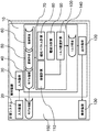
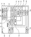
- FIG. 1 shows a configuration example of a calculation system including an analysis apparatus according to the present invention.
- Model information 40 element shape data 50 of a target model (usually called a mesh in the electromagnetic field analysis using the finite element method), magnetic flux density data 60 in each element, and the like are input from the input device 20 to the analysis device 10. This is designated by the instruction 30.
- the calculation program 70 includes a magnetization vector calculation block 80 that calculates a magnetization vector at each element at each step of the analysis time based on the magnetic flux density data 60, and an electromagnetic force calculation block 90 that calculates an electromagnetic force based on the calculated magnetization vector. Including. When calculating the torque of the rotating electrical machine, the distance of each element is calculated from the rotation center coordinates designated by the model information 40 and the element shape data 50, and the torque is calculated.
- the volume or area of each element is calculated by the volume calculation block 110 that calculates the volume or area of the element in parallel with these or based on the element shape data 50 before and after. It is assumed that the element shape 50 data and the magnetic flux density 60 data calculated using a calculation system different from the analysis device 10 are introduced into the analysis device 10 in advance using communication means or a storage medium. Yes.
- the torque per volume or area of each element is calculated from the electromagnetic force or torque acting on each element calculated previously and the volume or area of each element (in the description of this embodiment, (Referred to as torque density).
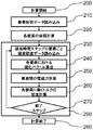
- FIG. 2 shows a calculation procedure of the torque density by the calculation program 70 when the shape of the magnetic body or coil to be analyzed does not change within the analysis time step.
- the input shows the case where the transient analysis result by the electromagnetic field analysis by the finite element method is used and the torque of each element (hereinafter referred to as torque density) is calculated as post processing.
- element shape data is first read into a storage area (210).
- the volume or area of each element is calculated from the shape data of each element (220).
- the calculated volume or area data of each element is stored in a storage area or saved in a file.
- the magnetic flux density of each element at the time corresponding to each time step is read (230), and the magnetization vector is calculated (240). Subsequently, the electromagnetic force exerted by each element is calculated (250). A torque density is calculated based on the calculated electromagnetic force, the volume or area for each area, and the distance from the center coordinate (260).
- the torque density calculation block 290 for each time step is repeatedly executed by the end step determination 270 until the time step to be calculated ends.
- the reading of the magnetic flux density data may be a procedure in which the target time steps are first read together and stored in the storage area.
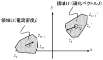
- the complex torque acting on the polygonal cross-section magnetic body by the polygon cross-section current as shown in FIG. 3 is calculated by the following formulas (1) to (10).
- the real part of Equation (1) is the torque generated in the target region.
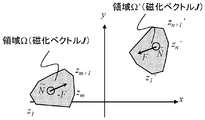
- Equation (11) is the torque generated in the calculation target region.
- FIG. 5 schematically shows the calculation points of the electromagnetic force by the Maxwell stress method and the nodal force method, which have been conventionally used for calculating the electromagnetic force, and the method of the present invention.
- the Maxwell stress method calculation is performed using a normal vector of an integration surface covering a magnetic material to be calculated.
- the nodal force method the electromagnetic force is calculated for each node constituting the element. In both cases, the electromagnetic force applied to the element itself is not directly calculated, so interpolation calculation is indispensable for the difference converted into the element, and calculation errors due to the element shape and the boundary between the magnetic body and air are inevitable. .
- the force inside the magnetic body is not calculated and displayed.
- the torque density is also calculated for each element in the magnetic body or coil, so that the torque density of each element can be displayed particularly corresponding to the shape of the electromagnetic device.
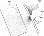
- FIG. 6 shows a calculation result of torque density calculated using the analysis apparatus of the present invention and displayed by applying the display method of the present invention.
- a part of the torque density distribution calculation result of the permanent magnet motor having the permanent magnet 430 in the rotor core 420 is enlarged and displayed.
- the direction of rotation is counterclockwise toward the plane of the paper.
- the torque zero is white, and the darker the black, the larger the positive torque. From the display result as shown in this figure, it can be seen that a relatively large positive torque is distributed in the outer peripheral portion of the rotor core 410 and the tooth tip portion of the stator core 400 in the calculated time step.
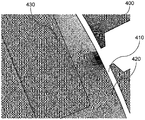
- FIG. 7 shows a calculation result of torque density calculated using the analysis apparatus of the present invention and displayed by applying the display method according to the second embodiment of the present invention.
- a part of the torque density distribution calculation result of the permanent magnet motor having the permanent magnet 430 in the rotor core 420 is enlarged and displayed.
- the rotation direction is counterclockwise toward the paper surface.
- the negative maximum torque density is white, and the darker the black, the larger the positive torque. From the display results as shown in this figure, it can be seen that relatively large positive and negative torques are distributed in the outer peripheral portion of the rotor core 410 and the tooth tip portion of the stator core 400 in the calculated time step.
- FIG. 8 is a diagram showing a calculation procedure executed by a calculation program in the analysis apparatus according to the third embodiment of the present invention.
- the torque density integration (310) is added to the calculation procedure in the first embodiment.
- FIG. 9 is a diagram showing a calculation system according to the fourth embodiment.
- a mesh model creation program 510 and an electromagnetic field analysis program 520 are provided in one calculation system 150.
- the mesh model creation program 510 generates the element shape data 50 and passes it to the electromagnetic field analysis program 520 and the analysis device 10.
- the electromagnetic field analysis program 520 calculates the magnetic flux density data 60 for each element of the element shape data 50 and passes it to the analysis apparatus 10. In the case of analysis involving movement of an object in the analysis region, either the element shape data 50 or the magnetic flux density data 60 is described including the displacement amount, or a separate displacement amount data file is prepared.
- Element shape data and magnetic flux density data necessary for calculating electromagnetic force or torque can be generated in one calculation system, so that calculation can be executed without moving data via a medium or the like. it can.
Landscapes
- Engineering & Computer Science (AREA)
- Physics & Mathematics (AREA)
- Theoretical Computer Science (AREA)
- General Physics & Mathematics (AREA)
- Geometry (AREA)
- Evolutionary Computation (AREA)
- General Engineering & Computer Science (AREA)
- Computer Hardware Design (AREA)
- Computational Mathematics (AREA)
- Mathematical Analysis (AREA)
- Mathematical Optimization (AREA)
- Pure & Applied Mathematics (AREA)
- Control Of Electric Motors In General (AREA)
Abstract
電磁界解析において磁性体やコイルに働くトルクの密度を要素ごとに計算する電磁界解析装置、その表示装置、およびこれらを用いた計算システムを提供する。 要素ごとの複素形式の磁化ベクトルから、各々の前記要素におけるトルク密度を計算するよう電磁界解析装置10を構成する。好ましくは、計算したトルク密度を解析の時間ステップに対して積算あるいは平均し、また、移動方向を基準としてトルク密度の値を色あるいは濃淡によるコンター表示を行うよう、電磁界解析装置120、その表示装置130、およびこれらを用いた計算システム150を構成する。
Description
本発明は、電磁界解析装置、その表示装置、およびこれらを用いた計算システムに関するものである。
電磁界解析を用いて電磁力やトルクを算出する方法として、以下のような技術が公開されている。
特許文献1では、有限要素法による電磁界と構造との連成解析を行う際に、電磁界解析に適した第1メッシュを用いて電磁界解析を行い、第1メッシュに含まれる各節点又は各要素辺での電磁界の値を用いて、構造解析に適した第2メッシュに含まれる各節点又は各要素辺での電磁界を計算し、計算した電磁界から、第2メッシュに含まれる各節点での電磁力の表現である節点力を算出し、第2メッシュを用いて構造解析を行う方法が示されている。
特許文献2では、コイルを有する固定子及び導体部を有する回転子を備えた誘導モータの数値解析モデルに基づいて、該数値解析モデルの定常状態における磁気ベクトルポテンシャルを算出する磁界解析装置に、前記コイルに与えられるべき電流又は電圧の第1周波数を取得する取得手段と、該取得手段が取得した第1周波数、及び前記固定子に対する前記回転子のすべり量を乗算して得られる第2周波数を算出する手段と、前記数値解析モデルの固定子部分における磁気ベクトルポテンシャルが第1周波数で正弦波振動し、且つ前記数値解析モデルの回転子部分における磁気ベクトルポテンシャルが第2周波数で正弦波振動した場合の磁気ベクトルポテンシャルを算出する周波数応答解析手段とを備える方法が示されている。
例えば回転電機の設計段階では、電磁界解析結果を元に出力となるトルクを増加させるため、磁気回路を構成する鉄心形状の変更によるトルクの時間変化を計算する場合がある。しかしながら、従来から磁性体に働く電磁力を計算するために用いられてきた接点力法では、要素を構成する節点に働く電磁力を計算しているために、特許文献1において節点力を構造解析用メッシュに移し替える際と同じように補間による誤差が不可避である。
そこで本発明は、電磁界解析において磁性体やコイルに働くトルクの密度を要素ごとに計算する電磁界解析装置、その表示装置、およびこれらを用いた計算システムを提供することを目的とする。
上記課題を解決するために、例えば請求の範囲に記載の構成を採用する。
本願は上記課題を解決する手段を複数含んでいるが、その一例を挙げるならば、要素ごとの複素形式の磁化ベクトルから、各々の前記要素におけるトルク密度を計算することを特徴とする。
本発明によれば、電磁界解析において磁性体やコイルに働くトルクの密度を要素ごとに計算する電磁界解析装置、その表示装置、およびこれらを用いた計算システムを提供することができる。
上記した以外の課題、構成及び効果は、以下の実施例の説明により明らかにされる。
以下、本発明の実施例について、図面に基づき説明する。以下の説明では、現在電磁界解析で多く用いられる有限要素法による電磁界解析結果と本発明を組合せた方法を想定した説明とするが、他の微分方程式による解析方法、あるいは積分方的式による解析方法と組み合わせても良い。
本発明による解析装置を含む計算システムの構成例を図1に示した。
解析装置10に入力装置20から、モデル情報40、対象とするモデル(有限要素法を用いた電磁界解析では通例、メッシュと呼ぶ)の要素形状データ50、各要素における磁束密度データ60などを入力指示30により指定する。
計算プログラム70は、磁束密度データ60に基づいて解析時間の各ステップで各要素における磁化ベクトルを計算する磁化ベクトル計算ブロック80、計算した磁化ベクトルに基づいて電磁力を計算する電磁力計算ブロック90を含む。回転電機のトルクを計算する場合にはモデル情報40で指定する回転中心座標と要素形状データ50から各要素の距離を算出し、トルクを計算する。
これらと並行して、あるいは前後に要素形状データ50に基づいて、要素の体積あるいは面積を計算する体積計算ブロック110により各要素の体積あるいは面積を計算する。要素形状50のデータや磁束密度60のデータは解析装置10とは別の計算システムを用いて計算したものを予め通信手段や記憶媒体を用いて解析装置10に導入しておくことを想定している。
次に、トルク密度計算ブロック100において、前までに計算した各要素に働く電磁力あるいはトルクと各要素の体積乃至面積から各要素の体積乃至面積あたりのトルク(本実施例の説明では、これをトルク密度と呼ぶ)を計算する。
図2に解析対象とする磁性体あるいはコイルの形状が解析時間ステップ内で変化しない場合の計算プログラム70によるトルク密度の計算手順を示す。入力には有限要素法による電磁界解析による過渡解析結果を用い、ポスト処理として各要素のトルク(以下、トルク密度と呼ぶ)を計算する場合を示している。
計算を開始(200)すると、まず要素形状データを記憶領域に読み込む(210)。次に各要素の形状データから各要素の体積あるいは面積を計算する(220)。計算した各要素の体積あるいは面積のデータは記憶領域に格納しておくか、ファイルに保存する。
次に、時間ステップごと該当時間における各要素の磁束密度を読み込み(230)、磁化ベクトルを算出する(240)。続いて各要素間で互いが及ぼす電磁力を計算する(250)。計算した電磁力と、面積ごとの体積乃至面積、さらに中心座標からの距離を元にトルク密度を計算する(260)。
時間ステップごとのトルク密度算出ブロック290は計算対象とする時間ステップが終了するまで終了ステップ判定270により繰り返し実行する。なお、磁束密度データの読み込みは対象時間ステップ分を最初にまとめて読み込み、記憶領域に保存する手順としても良い。
本発明で用いるトルク密度の計算方法について以下に説明する。
図3に示すような多角形断面の電流によって多角形断面の磁性体に作用する複素形式のトルクは、以下の数式(1)~(10)で計算される。数式(1)の実部が対象領域に生じるトルクとなる。










また、図4に示すような2つの多角形断面の磁性体に作用する電磁力から、領域Ω’の磁性体全体に作用する点Z0まわりの複素形式のトルクは、以下の数式(11)~(17)で計算される。同記号は数式(6)~(9)と同様である。数式(11)の実部が計算対象領域に生じるトルクとなる。






回転電機におけるトルク計算では、コイルと磁性体、磁性体と磁性体に働く電磁力の場合を考える。すなわち、一様な電流ないし磁化ベクトルが分布した要素を多角形の領域ΩおよびΩ’として、互いがおよぼす電磁力による回転中心回りのトルクを計算する。このトルクを各要素の体積乃至面積で除することでトルク密度の計算結果を得る。
図5に従来電磁力の算出に用いられてきたマクスウェル応力法と節点力法、本発明の手法による電磁力の算出箇所を模式的に示した。マクスウェル応力法では計算対象となる磁性体を覆う積分面の法線ベクトルを用いて計算する。また、節点力法では、要素を構成する各節点について電磁力を計算する。いずれも要素自体にかかる電磁力を直接計算するのではないため、要素に換算する差異には補間計算が不可欠であり、要素形状や磁性体と空気との境界部分などによる計算誤差が不可避となる。
このため、通常は接点力法によるトルク計算の場合には、磁性体内部の力は計算されず、表示されない。一方、本発明の方法によれば磁性体あるいはコイル内の各要素についてもトルク密度を計算するため、特に電磁機器の形状に対応して各要素のトルク密度を表示することができる。
図6に本発明の解析装置を用いて計算し、本発明の表示方法を適用して表示したトルク密度の計算結果を示す。回転子鉄心420中に永久磁石430を有する永久磁石モータのトルク密度分布計算結果の一部を拡大表示したものである。回転方向は紙面に向かって反時計回りであり、トルクゼロを白として、黒が濃いほど正トルクが大きい表示としている。この図のように表示結果から、計算した時間ステップにおいては、回転子鉄心410の外周部と固定子鉄心400のティース先端部分とに比較的大きな正トルクが分布していることが分かる。
図7に本発明の解析装置を用いて計算し、本発明の実施例2による表示方法を適用して表示したトルク密度の計算結果を示す。回転子鉄心420中に永久磁石430を有する永久磁石モータのトルク密度分布計算結果の一部を拡大表示したものである。回転方向は紙面に向かって反時計回りであり、負の最大トルク密度を白として、黒が濃いほど正トルクが大きい表示としている。この図のように表示結果から、計算した時間ステップにおいては、回転子鉄心410の外周部と固定子鉄心400のティース先端部分とに比較的大きな正負トルクが分布していることが分かる。
図8は本発明の実施例3による解析装置内の計算プログラムが実行する計算の手順を示す図である。
実施例1における計算手順にトルク密度の積算(310)を追加している。
これにより、計算対象ステップを通じての積算値および平均値を算出して、各要素における時間平均した電磁力やトルク密度を計算することができる。
図9は実施例4による計算システムを示す図である。
1つの計算システム150内に解析装置10の他、メッシュモデル作成プログラム510および電磁界解析プログラム520を備えている。
メッシュモデル作成プログラム510は要素形状データ50を生成し、電磁界解析プログラム520および解析装置10に受け渡す。電磁界解析プログラム520は要素形状データ50の各要素について磁束密度データ60を計算して、解析装置10に受け渡す。解析領域内で物体の移動を伴う解析の場合には要素形状データ50または磁束密度データ60のいずれかに変位量も含めて記載するか、別途変位量データファイルを用意する。
電磁力乃至トルクを計算するために必要な要素形状データならびに磁束密度データを1つの計算システム内で生成することができるため、媒体等を介したデータの移動など行わずとも計算を実行することができる。
10 解析装置
20 入力装置
40 モデル情報
50 要素形状データ
60 磁束密度データ
70 計算プログラム
80 磁化ベクトル計算ブロック
90 電磁力計算ブロック
100 トルク密度計算ブロック
110 体積計算ブロック
130 表示装置
400 固定子鉄心
420 回転子鉄心
430 永久磁石
510,540,570 節点
520,550,580 要素
530,560,590 電磁力の向き
20 入力装置
40 モデル情報
50 要素形状データ
60 磁束密度データ
70 計算プログラム
80 磁化ベクトル計算ブロック
90 電磁力計算ブロック
100 トルク密度計算ブロック
110 体積計算ブロック
130 表示装置
400 固定子鉄心
420 回転子鉄心
430 永久磁石
510,540,570 節点
520,550,580 要素
530,560,590 電磁力の向き
Claims (5)
- 要素ごとの複素形式の磁化ベクトルから、各々の前記要素におけるトルク密度を計算する電磁界解析装置。
- 請求項2に記載の電磁界解析装置において、
計算したトルク密度を解析の時間ステップに対して積算あるいは平均する電磁界解析装置。 - 請求項1又は2に記載の電磁界解析装置を備え、
前記電磁界解析装置により計算されたトルク密度を表示する表示装置。 - 請求項3に記載の表示装置であって、
前記電磁界解析装置により計算されたトルク密度について、
移動方向を基準としてトルク密度の値を色あるいは濃淡によるコンター表示を行う表示装置。 - 請求項1又は2に記載の電磁界解析装置或いは請求項3又は4に記載の表示装置を含み、
要素形状を作成するメッシュモデル作成プログラムと、
磁束密度を計算する電磁界解析プログラムとを含み、
要素形状のデータと磁束密度のデータを解析装置に受け渡して計算を実行する計算システム。
Applications Claiming Priority (2)
| Application Number | Priority Date | Filing Date | Title |
|---|---|---|---|
| JP2014-197764 | 2014-09-29 | ||
| JP2014197764A JP6286331B2 (ja) | 2014-09-29 | 2014-09-29 | 電磁界解析装置、その表示装置、およびこれらを用いた計算システム |
Publications (1)
| Publication Number | Publication Date |
|---|---|
| WO2016051980A1 true WO2016051980A1 (ja) | 2016-04-07 |
Family
ID=55630026
Family Applications (1)
| Application Number | Title | Priority Date | Filing Date |
|---|---|---|---|
| PCT/JP2015/073173 Ceased WO2016051980A1 (ja) | 2014-09-29 | 2015-08-19 | 電磁界解析装置、その表示装置、およびこれらを用いた計算システム |
Country Status (2)
| Country | Link |
|---|---|
| JP (1) | JP6286331B2 (ja) |
| WO (1) | WO2016051980A1 (ja) |
Cited By (1)
| Publication number | Priority date | Publication date | Assignee | Title |
|---|---|---|---|---|
| JP2022156660A (ja) * | 2021-03-31 | 2022-10-14 | 日本製鉄株式会社 | コア設計用処理方法、コア設計用処理装置、およびプログラム |
Citations (3)
| Publication number | Priority date | Publication date | Assignee | Title |
|---|---|---|---|---|
| JP2004029930A (ja) * | 2002-06-21 | 2004-01-29 | Japan Research Institute Ltd | 節点力算出方法、節点力算出装置、コンピュータプログラム、及び記録媒体 |
| JP2012128492A (ja) * | 2010-12-13 | 2012-07-05 | Sumitomo Heavy Ind Ltd | 解析装置および解析方法 |
| JP2014071689A (ja) * | 2012-09-28 | 2014-04-21 | Jsol Corp | 解析装置、解析方法及びコンピュータプログラム |
Family Cites Families (1)
| Publication number | Priority date | Publication date | Assignee | Title |
|---|---|---|---|---|
| US9286419B2 (en) * | 2010-07-19 | 2016-03-15 | Terje Graham Vold | Computer simulation of electromagnetic fields |
-
2014
- 2014-09-29 JP JP2014197764A patent/JP6286331B2/ja active Active
-
2015
- 2015-08-19 WO PCT/JP2015/073173 patent/WO2016051980A1/ja not_active Ceased
Patent Citations (3)
| Publication number | Priority date | Publication date | Assignee | Title |
|---|---|---|---|---|
| JP2004029930A (ja) * | 2002-06-21 | 2004-01-29 | Japan Research Institute Ltd | 節点力算出方法、節点力算出装置、コンピュータプログラム、及び記録媒体 |
| JP2012128492A (ja) * | 2010-12-13 | 2012-07-05 | Sumitomo Heavy Ind Ltd | 解析装置および解析方法 |
| JP2014071689A (ja) * | 2012-09-28 | 2014-04-21 | Jsol Corp | 解析装置、解析方法及びコンピュータプログラム |
Cited By (2)
| Publication number | Priority date | Publication date | Assignee | Title |
|---|---|---|---|---|
| JP2022156660A (ja) * | 2021-03-31 | 2022-10-14 | 日本製鉄株式会社 | コア設計用処理方法、コア設計用処理装置、およびプログラム |
| JP7575687B2 (ja) | 2021-03-31 | 2024-10-30 | 日本製鉄株式会社 | コア設計用処理方法、コア設計用処理装置、およびプログラム |
Also Published As
| Publication number | Publication date |
|---|---|
| JP2016071466A (ja) | 2016-05-09 |
| JP6286331B2 (ja) | 2018-02-28 |
Similar Documents
| Publication | Publication Date | Title |
|---|---|---|
| JP6468826B2 (ja) | シミュレーション装置及びコンピュータプログラム | |
| Lee et al. | Determination of parameters considering magnetic nonlinearity in an interior permanent magnet synchronous motor | |
| KR101993197B1 (ko) | 동기기의 운전 방법 | |
| Ionel et al. | Ultrafast finite-element analysis of brushless PM machines based on space–time transformations | |
| Martinez et al. | Enhancement of permanent-magnet synchronous machines torque estimation using pulsating high-frequency current injection | |
| Putek et al. | Topology optimization of rotor poles in a permanent-magnet machine using level set method and continuum design sensitivity analysis | |
| CN102870321B (zh) | 用于确定电驱动机的输出转矩的方法和装置 | |
| CN110705088A (zh) | 一种基于磁网络的永磁电机建模和电磁性能计算方法 | |
| CN108291939A (zh) | 低磁芯损耗内置磁体电机设计 | |
| JP2009176061A (ja) | インダクタンステーブル作成方法、インダクタンステーブル作成装置、シミュレーション装置及びコンピュータプログラム | |
| JP6286331B2 (ja) | 電磁界解析装置、その表示装置、およびこれらを用いた計算システム | |
| Laborda et al. | Variable leakage flux permanent magnet synchronous machine PM temperature estimation based on PM flux linkage | |
| CN112204560A (zh) | 计算机程序、模拟方法和模拟装置 | |
| JP2008286779A (ja) | Ipmモータのためのトルク推定器 | |
| JP2016118831A (ja) | 特性テーブル作成装置及びコンピュータプログラム | |
| JP6311152B2 (ja) | 誘導電動機のための回転子磁束推定装置 | |
| KR101591198B1 (ko) | 영구자석 동기 전동기의 인덕턴스 추정기 및 영구자석 동기 전동기의 인덕턴스 추정방법, 그 방법을 수행하기 위한 프로그램이 기록된 기록매체 | |
| Piña et al. | Extended model of interior permanent magnet synchronous motors to include harmonics in d-and q-axes flux linkages | |
| CN118643684A (zh) | 基于磁动势场子域的永磁电机气隙磁场解析方法 | |
| Kumar et al. | Magnetic field analysis of induction motor for optimal cooling duct design | |
| JP7205370B2 (ja) | モデル特性算出装置、モデル特性算出方法、及びプログラム | |
| Bramerdorfer et al. | Multi-harmonic design and optimization of PMSMs | |
| Cros et al. | Influence of the magnetic model accuracy on the optimal design of a car alternator | |
| JP6108114B2 (ja) | 永久磁石形同期電動機の制御装置 | |
| Ebrahimi | Analytical modeling of permanent magentic synchronous motors considering spatial harmonics |
Legal Events
| Date | Code | Title | Description |
|---|---|---|---|
| 121 | Ep: the epo has been informed by wipo that ep was designated in this application |
Ref document number: 15847024 Country of ref document: EP Kind code of ref document: A1 |
|
| NENP | Non-entry into the national phase |
Ref country code: DE |
|
| 122 | Ep: pct application non-entry in european phase |
Ref document number: 15847024 Country of ref document: EP Kind code of ref document: A1 |