WO2016047672A1 - Wireless base station and wireless terminal - Google Patents
Wireless base station and wireless terminal Download PDFInfo
- Publication number
- WO2016047672A1 WO2016047672A1 PCT/JP2015/076891 JP2015076891W WO2016047672A1 WO 2016047672 A1 WO2016047672 A1 WO 2016047672A1 JP 2015076891 W JP2015076891 W JP 2015076891W WO 2016047672 A1 WO2016047672 A1 WO 2016047672A1
- Authority
- WO
- WIPO (PCT)
- Prior art keywords
- base station
- wireless
- wireless terminal
- wireless lan
- radio base
- Prior art date
Links
- 238000010295 mobile communication Methods 0.000 claims abstract description 79
- 238000012545 processing Methods 0.000 claims abstract description 40
- 238000000034 method Methods 0.000 claims description 146
- 230000008569 process Effects 0.000 claims description 126
- 238000004891 communication Methods 0.000 claims description 39
- 238000005259 measurement Methods 0.000 claims description 38
- 238000010586 diagram Methods 0.000 description 20
- 230000004044 response Effects 0.000 description 11
- 238000005457 optimization Methods 0.000 description 8
- 230000006870 function Effects 0.000 description 7
- 230000007246 mechanism Effects 0.000 description 6
- 230000001960 triggered effect Effects 0.000 description 5
- 230000005540 biological transmission Effects 0.000 description 4
- 230000015556 catabolic process Effects 0.000 description 3
- 238000006731 degradation reaction Methods 0.000 description 3
- 239000000523 sample Substances 0.000 description 3
- 230000007774 longterm Effects 0.000 description 2
- 230000011664 signaling Effects 0.000 description 2
- 230000007704 transition Effects 0.000 description 2
- AYFVYJQAPQTCCC-GBXIJSLDSA-N L-threonine Chemical compound C[C@@H](O)[C@H](N)C(O)=O AYFVYJQAPQTCCC-GBXIJSLDSA-N 0.000 description 1
- 230000009286 beneficial effect Effects 0.000 description 1
- 230000010267 cellular communication Effects 0.000 description 1
- 230000008859 change Effects 0.000 description 1
- 230000003111 delayed effect Effects 0.000 description 1
- 238000005516 engineering process Methods 0.000 description 1
- 238000011156 evaluation Methods 0.000 description 1
- 238000012544 monitoring process Methods 0.000 description 1
- 238000012360 testing method Methods 0.000 description 1
Images


Classifications
-
- H—ELECTRICITY
- H04—ELECTRIC COMMUNICATION TECHNIQUE
- H04W—WIRELESS COMMUNICATION NETWORKS
- H04W36/00—Hand-off or reselection arrangements
- H04W36/0005—Control or signalling for completing the hand-off
- H04W36/0083—Determination of parameters used for hand-off, e.g. generation or modification of neighbour cell lists
- H04W36/0085—Hand-off measurements
-
- H—ELECTRICITY
- H04—ELECTRIC COMMUNICATION TECHNIQUE
- H04W—WIRELESS COMMUNICATION NETWORKS
- H04W36/00—Hand-off or reselection arrangements
- H04W36/0005—Control or signalling for completing the hand-off
- H04W36/0083—Determination of parameters used for hand-off, e.g. generation or modification of neighbour cell lists
- H04W36/00837—Determination of triggering parameters for hand-off
- H04W36/008375—Determination of triggering parameters for hand-off based on historical data
-
- H—ELECTRICITY
- H04—ELECTRIC COMMUNICATION TECHNIQUE
- H04W—WIRELESS COMMUNICATION NETWORKS
- H04W36/00—Hand-off or reselection arrangements
- H04W36/0005—Control or signalling for completing the hand-off
- H04W36/0083—Determination of parameters used for hand-off, e.g. generation or modification of neighbour cell lists
- H04W36/00837—Determination of triggering parameters for hand-off
-
- H—ELECTRICITY
- H04—ELECTRIC COMMUNICATION TECHNIQUE
- H04W—WIRELESS COMMUNICATION NETWORKS
- H04W36/00—Hand-off or reselection arrangements
- H04W36/14—Reselecting a network or an air interface
-
- H—ELECTRICITY
- H04—ELECTRIC COMMUNICATION TECHNIQUE
- H04W—WIRELESS COMMUNICATION NETWORKS
- H04W36/00—Hand-off or reselection arrangements
- H04W36/14—Reselecting a network or an air interface
- H04W36/144—Reselecting a network or an air interface over a different radio air interface technology
- H04W36/1446—Reselecting a network or an air interface over a different radio air interface technology wherein at least one of the networks is unlicensed
-
- H—ELECTRICITY
- H04—ELECTRIC COMMUNICATION TECHNIQUE
- H04W—WIRELESS COMMUNICATION NETWORKS
- H04W36/00—Hand-off or reselection arrangements
- H04W36/16—Performing reselection for specific purposes
- H04W36/22—Performing reselection for specific purposes for handling the traffic
-
- H—ELECTRICITY
- H04—ELECTRIC COMMUNICATION TECHNIQUE
- H04W—WIRELESS COMMUNICATION NETWORKS
- H04W36/00—Hand-off or reselection arrangements
- H04W36/34—Reselection control
- H04W36/38—Reselection control by fixed network equipment
-
- H—ELECTRICITY
- H04—ELECTRIC COMMUNICATION TECHNIQUE
- H04W—WIRELESS COMMUNICATION NETWORKS
- H04W84/00—Network topologies
- H04W84/02—Hierarchically pre-organised networks, e.g. paging networks, cellular networks, WLAN [Wireless Local Area Network] or WLL [Wireless Local Loop]
- H04W84/10—Small scale networks; Flat hierarchical networks
- H04W84/12—WLAN [Wireless Local Area Networks]
-
- H—ELECTRICITY
- H04—ELECTRIC COMMUNICATION TECHNIQUE
- H04W—WIRELESS COMMUNICATION NETWORKS
- H04W88/00—Devices specially adapted for wireless communication networks, e.g. terminals, base stations or access point devices
- H04W88/02—Terminal devices
- H04W88/06—Terminal devices adapted for operation in multiple networks or having at least two operational modes, e.g. multi-mode terminals
-
- H—ELECTRICITY
- H04—ELECTRIC COMMUNICATION TECHNIQUE
- H04W—WIRELESS COMMUNICATION NETWORKS
- H04W88/00—Devices specially adapted for wireless communication networks, e.g. terminals, base stations or access point devices
- H04W88/08—Access point devices
Definitions
- This application relates to a radio base station and a radio terminal used in a system that performs a switching process for switching a standby destination or a connection destination between a coverage area of a mobile communication network and a coverage area of a wireless LAN.
- the switching process is performed based on whether the first information on the mobile communication network side satisfies the first condition and whether the second information on the wireless LAN side satisfies the second condition.
- the first information on the mobile communication network side is, for example, the measurement of the signal level (RSRP: Reference Signal Received Power) of the received signal and the signal quality (RSRQ; Reference Signal Received Quality) of the received signal. It is a result (RSRQmeas).
- the second information on the wireless LAN side is, for example, a wireless LAN channel utilization value, a wireless LAN backhaul value, and a signal strength (RSSI: Received Signal Strength Indicator) of the received signal.
- a determination parameter for determining whether or not to perform a switching process for switching a standby destination or a connection destination between a mobile communication network and a wireless LAN is performed from a wireless base station provided in the mobile communication network to a wireless terminal. Be notified.
- the determination parameter there are an individual parameter individually notified to the wireless terminal and a notification parameter notified to the wireless terminal.
- the base station constitutes a mobile communication network.
- the wireless base station includes a controller that measures a stay time in which a wireless terminal stays in the wireless LAN.
- the staying time is determined when the wireless terminal performs a first process of switching a standby destination or connection destination from the mobile communication network to the wireless LAN, and then the wireless terminal waits or connects from the wireless LAN to the mobile communication network. This is the time until the second process of switching the destination.
- FIG. 1 is a diagram illustrating a communication system 1 according to the embodiment.
- FIG. 2 is a block diagram illustrating the radio terminal 10 according to the embodiment.
- FIG. 3 is a block diagram illustrating the radio base station 100 according to the embodiment.
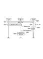
- FIG. 4 is a sequence diagram for explaining the operation (A-1) according to the embodiment.
- FIG. 5 is a sequence diagram for explaining the operation (A-2) according to the embodiment.
- FIG. 6 is a sequence diagram for explaining the operation (B-1) according to the embodiment.
- FIG. 7 is a sequence diagram for explaining the operation (B-2) according to the embodiment.
- FIG. 8 is a sequence diagram for explaining the operation (C-1) according to the embodiment.
- FIG. 9 is a sequence diagram for explaining the operation (C-2) according to the embodiment.
- FIG. 10 is a sequence diagram for explaining the operation (C-3) according to the embodiment.
- the radio base station optimizes the determination parameter.
- the determination parameter cannot be optimized appropriately.
- the present application has been made to solve the above-described problem, and provides a radio base station and a radio terminal that enable a radio base station to acquire information for optimizing a determination parameter. For the purpose.
- the radio base station constitutes a mobile communication network.
- the wireless base station includes a controller that measures a stay time in which a wireless terminal stays in the wireless LAN.
- the staying time is determined when the wireless terminal performs a first process of switching a standby destination or connection destination from the mobile communication network to the wireless LAN, and then the wireless terminal waits or connects from the wireless LAN to the mobile communication network. This is the time until the second process of switching the destination.
- the first process is a process in which the wireless terminal switches a standby destination or a connection destination from its own wireless base station to the wireless LAN.
- the second process is a process in which the wireless terminal switches a standby destination or a connection destination from the wireless LAN to its own wireless base station.
- the first process is a process in which the wireless terminal switches a standby destination or a connection destination from its own wireless base station to the wireless LA.
- the second process is a process in which the wireless terminal switches a standby destination or a connection destination from the wireless LAN to another wireless base station different from its own wireless base station.
- the controller detects that the wireless terminal has performed the second process by receiving information indicating that the wireless terminal has performed the second process from the other wireless base station. To do.
- the controller receives the information indicating that the wireless terminal has executed the second process from an entity configuring the wireless LAN, so that the wireless terminal has performed the second process. To detect.
- the controller determines a parameter based on the stay time.
- the parameter is a parameter used when the wireless terminal determines whether to switch a standby destination or a connection destination for the wireless LAN from the mobile communication network.
- a wireless terminal includes a controller that measures a staying time staying in a wireless LAN, a transmitter that transmits a message based on the staying time measurement result to a wireless base station configuring a mobile communication network, and Is provided.
- a controller that measures a staying time staying in a wireless LAN
- a transmitter that transmits a message based on the staying time measurement result to a wireless base station configuring a mobile communication network, and Is provided.
- For the stay time after performing a first process of switching a standby destination or a connection destination from the mobile communication network to the wireless LAN, a second process of switching a standby destination or a connection destination from the wireless LAN to the mobile communication network is performed. It is time until.
- the message is a message indicating that the time from when the first process is performed to when the second process is performed is within a predetermined time.
- the message is a message indicating the value of the stay time.
- the message is a notification indicating that the wireless terminal has performed the second process after performing the first process and that a predetermined phenomenon has occurred.
- the wireless base station receives a message based on a measurement result of a staying time in which the wireless terminal stayed in the wireless LAN from a wireless terminal connected to the wireless LAN or an entity constituting the wireless LAN.
- a receiver is provided.
- the staying time is determined when the wireless terminal performs a first process of switching a standby destination or a connection destination for the wireless LAN from the mobile communication network, and then the wireless terminal transmits the wireless LAN to the mobile communication network. This is the time until the second process of switching the standby destination or connection destination.
- the message is a message indicating that a time from when the wireless terminal performs the first process to when the second process is performed is within a certain period.
- the message is a message indicating the stay time.
- the message is a notification indicating that the wireless terminal has performed the second process after performing the first process and that a predetermined phenomenon has occurred.
- the radio base station is a radio base station constituting a mobile communication network.
- a predetermined phenomenon occurs when the wireless terminal switches the standby destination or connection destination from the mobile communication network to the wireless LAN and then switches the standby destination or connection destination from the wireless LAN to the mobile communication network.
- a controller that determines a parameter used to determine whether or not the wireless terminal switches a standby destination or a connection destination between the mobile communication network and the wireless LAN when it is detected.
- the radio base station further includes a receiver that receives a notification indicating that the predetermined phenomenon has occurred from an entity constituting the wireless LAN or the wireless terminal.
- the controller detects that the predetermined phenomenon has occurred when the receiver receives a notification indicating that the predetermined phenomenon has occurred.
- the predetermined phenomenon is a phenomenon that satisfies a predetermined condition.
- the predetermined condition is that a time elapsed from when the wireless terminal switches the standby destination or connection destination from the mobile communication network to the wireless LAN until the standby destination or connection destination is switched from the wireless LAN to the mobile communication network is predetermined. In time.
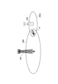
- FIG. 1 is a diagram illustrating a communication system 1 according to the first embodiment.
- the communication system 1 includes a radio base station 100 and an access point 200. Further, the communication system 1 includes a wireless terminal 10 that can be connected to the wireless base station 100 or the access point 200.
- the wireless terminal 10 is a terminal such as a mobile phone or a tablet.
- the wireless terminal 10 has a function of performing wireless communication with the access point 200 in addition to a function of performing wireless communication with the wireless base station 100.
- the radio base station 100 has a first coverage area 100A, and provides a mobile communication service represented by LTE (Long Term Evolution) in the first coverage area 100A.
- LTE Long Term Evolution
- E-UTRAN Evolved Universal Terrestrial Radio Access Network
- the radio base station 100 is a network device.
- the radio base station 100 manages one or a plurality of cells, and the first coverage area 100A is configured by one or a plurality of cells.
- the radio base station 100 is an entity of a mobile communication network.
- the cell may be considered as a term indicating a geographical area, or may be considered as a function of performing wireless communication with the wireless terminal 10.
- the access point 200 has a second coverage area 200A, and provides a wireless LAN service in the second coverage area 200A.
- the access point 200 is a wireless LAN entity. At least a part of the second coverage area 200A overlaps with the first coverage area 100A. The entire second coverage area 200A may overlap with the first coverage area 100A. In general, the second coverage area 200A is smaller than the first coverage area 100A.
- a method for performing a switching process for example, network selection and traffic steering in which a wireless terminal switches a standby destination or a connection destination between a mobile communication network and a wireless LAN
- the radio terminal 10 in the RRC connected state or the RRC idle state performs a process of switching to select a network that transmits and receives traffic from a mobile communication network (cellular communication network) and a wireless LAN (WLAN communication network).
- a mobile communication network cellular communication network
- WLAN communication network wireless LAN
- the switching process is a process in which the wireless terminal switches a standby destination or a connection destination from the mobile communication network to the wireless LAN, and switches a standby destination or a connection destination from the wireless LAN to the mobile communication network. Includes both processing.
- the first information on the mobile communication network side is, for example, the measurement of the signal level (RSRP: Reference Signal Received Power) of the received signal and the signal quality (RSRQ; Reference Signal Received Quality) of the received signal. It is a result (RSRQmeas).
- RSRP Reference Signal Received Power
- RSSQ Reference Signal Received Quality
- the second information on the wireless LAN side includes, for example, a wireless LAN channel utilization value (ChannelUtilization WLAN), a wireless LAN downlink backhaul value (BackhaulRateDlWLAN), a wireless LAN uplink backhaul value (BackhaulRateUlWLAN), and a received signal It is a signal level (RSSI; Received Signal Strength Indicator).
- a wireless LAN channel utilization value (ChannelUtilization WLAN)
- BackhaulRateDlWLAN wireless LAN downlink backhaul value
- BackhaulRateUlWLAN wireless LAN uplink backhaul value
- RSSI Received Signal Strength Indicator
- the first condition for the wireless terminal to switch the standby destination or the connection destination from the mobile communication network to the wireless LAN is, for example, that either of the following conditions (1a) or (1b) is satisfied.
- the first condition may be that all of the following conditions (1a) to (1b) are satisfied.
- “Thresh ServingOffloadWLAN, LowP ” and “Thresh ServingOffloadWLAN, LowQ ” are thresholds provided from the radio base station 100 or predetermined thresholds.
- the second condition for the wireless terminal to switch the standby destination or the connection destination from the mobile communication network to the wireless LAN is, for example, that all of the following conditions (1c) to (1f) are satisfied.
- the second condition may be that any of the following conditions (1c) to (1f) is satisfied.
- Thre ChUtil WLAN, Low ”, “Thresh BackRateDLWLAN, High ”, “Thresh BackRate ULWLAN, High ”, and “Thresh BEACONSRSSI, High ” are predetermined thresholds provided from the radio base station 100.
- the first condition for the wireless terminal to switch the standby destination or connection destination from the wireless LAN to the mobile communication network is, for example, that the following conditions (2a) and (2b) are satisfied.
- the first condition may be that either of the following conditions (2a) or (2b) is satisfied.
- Three ServingOffloadWLAN, HighP ” and “Thresh ServingOffloadWLAN, HighQ ” are thresholds provided from the radio base station 100 or predetermined thresholds.
- the second condition for the wireless terminal to switch the standby destination or connection destination from the wireless LAN to the mobile communication network is, for example, that any of the following conditions (2c) to (2f) is satisfied.
- the second condition may be that all of the following conditions (2c) to (2f) are satisfied.
- ThreshChillWLAN, High ”, “ ThreshBackRateDLWLAN, Low ”, “ ThreshBackRateULWLAN, Low ”, and “ ThreshBEACONSRSSI, Low ” are thresholds provided from the radio base station 100 or predetermined thresholds.
- wireless terminal 10 may abbreviate
- the various threshold values described above are determination parameters (for example, RAN) for determining whether or not the wireless terminal performs a switching process for switching a standby destination or a connection destination between the mobile communication network and the wireless LAN. It is an example of assistance parameters.
- the determination parameter "Thresh ServingOffloadWLAN, LowP", “Thresh ServingOffloadWLAN, LowQ”, “Thresh ChUtilWLAN, Low”, “Thresh BackhRateDLWLAN, High”, “Thresh BackhRateULWLAN, High”, “Thresh BEACONSRSSI, High”, “Thresh “ ServingOffloadWLAN, HighP ”, “Thresh ServingOffloadWLAN, HighQ ”, “ ThreshChillWLAN, High ”, “Thresh BackRateDLWLAN, Low ”, “ ThreshRuB ”
- One or more values selected from “ w ” and “Thresh BEACONSRSSI, Low ” are included.
- the determination parameter may include a predetermined period (Tsteering WLAN ) in which the state where the first condition or the second condition is satisfied should continue.
- the determination parameter is a predetermined period (T350 timer value) that the wireless terminal 10 should hold an individual parameter to be described later when an offload process for switching a standby destination or a connection destination to the wireless LAN from the mobile communication network is performed. May be included.
- the determination parameters there are an individual parameter individually notified from the radio base station 100 to the radio terminal 10 and a notification parameter notified from the radio base station 100 to the radio terminal 10.
- the individual parameter is included in, for example, an RRC message (for example, RRC Connection Reconfiguration) transmitted from the radio base station 100 to the radio terminal 10.
- the broadcast parameter is included in, for example, an SIB broadcast from the radio base station 100 (for example, WLAN-OffloadConfig-r12). It should be noted that when the wireless terminal 10 receives an individual parameter in addition to the notification parameter, the wireless terminal 10 applies the individual parameter with priority over the notification parameter.
- FIG. 2 is a block diagram showing the radio terminal 10 according to the first embodiment.
- the wireless terminal 10 includes an LTE wireless communication unit 11 (transceiver / transmitter / receiver), a WLAN wireless communication unit 12 (transceiver / transmitter / receiver), and a control unit 13 (controller).
- LTE wireless communication unit 11 transmitter / receiver
- WLAN wireless communication unit 12 transmitter / receiver
- control unit 13 controller
- the LTE wireless communication unit 11 has a function of performing wireless communication with the wireless base station 100, and is configured by, for example, a wireless transceiver. For example, the LTE radio communication unit 11 periodically receives a reference signal from the radio base station 100. The LTE wireless communication unit 11 periodically measures the signal level (RSRP) of the reference signal and the signal quality (RSRQ) of the reference signal. The LTE radio communication unit 11 receives an individual parameter and a broadcast parameter from the radio base station 100 as determination parameters.
- RSRP signal level
- RSRQ signal quality
- the WLAN wireless communication unit 12 has a function of performing wireless communication with the access point 200, and is configured by a wireless transceiver, for example.
- the WLAN wireless communication unit 12 receives a beacon or a probe response from the access point 200.
- the beacon or probe response includes the BBS Load information element, and the channel usage value (ChannelUtilization WLAN) of the wireless LAN can be acquired from the BBS Load information element.
- the WLAN wireless communication unit 12 receives a response (GAS Response) returned from the access point 200 in response to a request (GAS (Generic Advertisement Service) Request) to the access point 200.
- the response (GAS Response) includes a wireless LAN downlink backhaul value (BackhaulRateDlWLAN) and a wireless LAN uplink backhaul value (BackhaulRateUlWLAN).
- ANQP Access Network Query Protocol
- WSP Wi-Fi Alliance
- the WLAN wireless communication unit 12 receives a signal from access point 200.
- the WLAN radio communication unit 12 measures the signal level (RSSI) of the received signal.
- the signal level (RSSI) of the received signal is the signal strength of the beacon or probe response.
- the control unit 13 includes a CPU (processor), a memory, and the like, and controls the wireless terminal 10. Specifically, the control unit 13 controls the LTE wireless communication unit 11 and the WLAN wireless communication unit 12. Further, the control unit 13 continues the state where the first information on the mobile communication network side satisfies the first condition and the second information on the wireless LAN side satisfies the second condition for a predetermined period. In this case, a switching process for switching a standby destination or a connection destination between the mobile communication network and the wireless LAN is executed.
- a switching process for switching a standby destination or a connection destination between the mobile communication network and the wireless LAN is executed.
- control unit 13 performs an offload process for switching the standby destination or connection destination from the mobile communication network to the wireless LAN, and then determines the standby destination or connection destination from the wireless LAN to the mobile communication network. Discard individual parameters when the re-offload process to switch is performed.
- control unit 13 is configured to start a predetermined timer (the above-described (T350 timer) that is started by the wireless terminal 10 when the transition to the idle state is performed in accordance with the offload process (T350 timer). In other words, the control unit 13 is configured to discard the individual parameter when the predetermined timer expires or stops.
- a predetermined timer the above-described (T350 timer) that is started by the wireless terminal 10 when the transition to the idle state is performed in accordance with the offload process (T350 timer).
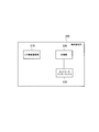
- FIG. 3 is a block diagram showing the radio base station 100 according to the first embodiment.
- the radio base station 100 includes an LTE radio communication unit 110 (transceiver / transmitter / receiver), a control unit 120 (controller), and a network interface 130.
- LTE radio communication unit 110 transmitter / receiver
- control unit 120 controller
- network interface 130 a network interface
- the LTE wireless communication unit 110 has a function of performing wireless communication with the wireless terminal 10. For example, the LTE wireless communication unit 110 periodically transmits a reference signal to the wireless terminal 10.
- the LTE wireless communication unit 110 is configured by a wireless transceiver, for example.
- the LTE wireless communication unit 110 transmits an individual parameter and a notification parameter as determination parameters to the wireless terminal 10.
- the LTE wireless communication unit 110 notifies the wireless terminal 10 of the individual parameters by the RRC message (for example, RRC Connection Reconfiguration), and notifies the wireless terminal 10 of the notification parameters by the SIB (for example, WLAN-OffloadConfig-r12). Notice.
- the RRC message for example, RRC Connection Reconfiguration
- SIB for example, WLAN-OffloadConfig-r12
- the control unit 120 includes a CPU (processor), a memory, and the like, and controls the radio base station 100. Specifically, the control unit 120 controls the LTE wireless communication unit 110 and the network interface 130. Note that a memory constituting the control unit 120 may function as a storage unit, or a memory constituting the storage unit may be provided separately from the memory constituting the control unit 120.
- the network interface 130 is connected to the neighboring base station via the X2 interface, and is connected to the MME / S-GW via the S1 interface.
- the network interface 130 is used for communication performed on the X2 interface and communication performed on the S1 interface.
- the network interface 130 may be connected to the access point 200 through a predetermined interface.
- the network interface 130 is used for communication with the access point 200.
- the first information is a measurement result (RSRPmeas) of the signal level (RSRP) of the reference signal or a measurement result (RSRQmeas) of the signal quality (RSRQ) of the reference signal, and the reference signal is periodically received in a short period.
- RSRQmeas is measured with a relatively short period. That is, RSRPmeas or RSRQmeas is continuously acquired in the time axis direction.
- the second information for example, BackhaulRateDlWLAN or BackhaulRateUlWLAN
- Radio base station 100 A case where the radio base station 100 has a UE stay timer that measures the stay time in which the radio terminal 10 has stayed in the wireless LAN will be described.
- FIG. 4 is a sequence diagram for explaining the operation (A-1) according to the embodiment.
- step S101 the radio terminal 10 executes an offload process from the radio base station 100 to the access point 200.
- the radio base station 100 starts the UE stay timer with the execution of the offload process as a trigger. For example, when the radio base station 100 detects the start or end of the offload process (completion of connection to the access point 200), the radio base station 100 starts the UE stay timer. Alternatively, the radio base station 100 starts the UE stay timer when the execution of the offload process is detected by a procedure in which the radio terminal 10 transitions to an idle state in a cell managed by the radio base station 100. That is, the radio base station 100 may start the UE stay timer using the release of the RRC connection with the radio terminal 10 as a trigger.
- a P-GW Packet data network Gateway
- the P-GW is, for example, a network node that performs various types of mobility control for the UE 100 and notifies the radio base station 100 of information indicating offload processing via a network node such as an MME corresponding to the control station.
- the radio base station 100 may start a UE stay timer triggered by reception of information indicating offload processing.
- step S103 the radio terminal 10 executes a re-offload process from the access point 200 to the radio base station 100.
- the radio base station 100 stops the UE stay timer using the execution of the re-offload process as a trigger. For example, the radio base station 100 stops the UE stay timer when the start or end of the re-offload process is detected. Alternatively, the radio base station 100 stops the UE stay timer when the radio terminal 10 detects the execution of the re-offload process in the cell managed by the radio base station 100 according to the procedure for transitioning to the connected state. That is, the radio base station 100 may stop the UE stay timer using the establishment of the RRC connection with the radio terminal 10 as a trigger. Alternatively, the radio base station 100 may stop the UE stay timer using a reception of an RRC connection request from the radio terminal 10 as a trigger. Alternatively, the radio base station 100 may stop the UE stay timer triggered by reception of information indicating the re-offload process from the P-GW.
- step S105 the radio base station 100 determines (analyzes) whether or not a ping-pong phenomenon has occurred based on the measured staying time.
- the radio base station 100 determines that the ping-pong phenomenon has occurred when the staying time is shorter (smaller) than the threshold value indicating that the ping-pong phenomenon has occurred. Therefore, when the time (stay time) elapsed from the offload processing to the reoffload processing is within a predetermined time, it is determined that the ping-pong phenomenon has occurred.
- the radio base station 100 when it is determined that the ping-pong phenomenon has occurred, the radio base station 100 optimizes the determination parameter. For example, the radio base station 100 sets a low threshold for the first information on the mobile communication network side. Alternatively, the wireless base station 100-1 sets a high threshold for the second information on the wireless LAN side. That is, the radio base station 100 sets a determination parameter that makes it difficult to perform offload processing to the wireless LAN.
- the radio base station 100 optimizes a timer (Tsteering WLAN Timer) indicating a predetermined period (Tsteering WLAN ).
- the timer is the minimum time (Tsteering) in which the state where the first information satisfies the first condition or the state where the second information satisfies the second condition should continue It is a timer for measuring WLAN ).
- the radio base station 100 sets the timer longer than the current set value.
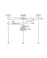
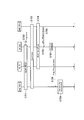
- FIG. 5 is a sequence diagram for explaining the operation (A-2) according to the embodiment.
- step S201 the wireless terminal 10 executes offload processing from the wireless base station 100-1 to the access point 200.
- the radio terminal 10 is in a connected state in a cell managed by the radio base station 100.
- step S202 the radio base station 100-1 starts the UE stay timer with the execution of the offload process as a trigger.
- the radio terminal 10 changes the cell in which the radio terminal 10 is located from the cell managed by the radio base station 100-1 to the cell managed by the radio base station 100-2 by the handover procedure.
- “in-service area” may be a standby state (RRC idle state) for a cell managed by the radio base station 100-1, or a connection state (connected to a cell managed by the radio base station 100-1). RRC connected state).
- the radio base station 100-1 may transmit information indicating that the UE stay timer of the radio terminal 10 is activated to the radio base station 100-2 in the handover procedure.
- step S204 the wireless terminal 10 executes a re-offload process from the access point 200 to the wireless base station 100-2.
- the radio base station 100-2 uses the execution of the re-offload process as a trigger to the radio base station 100-1 that is the source base station of the radio terminal 10 from the radio LAN to the radio base station 100-1.
- Information (Re-offload indicator (Re-offload Indicator)) indicating that the re-offload processing to 100-1 has been executed is transmitted.
- the radio base station 100-2 transmits a Re-offload indicator triggered by reception of information indicating a re-offload process from the P-GW.
- the Re-offload indicator (Re-offload Indicator) is transmitted as an example.
- the wireless terminal 10 performs the re-offload processing from the wireless LAN to the wireless base station 100-1. It may be a simple notification indicating that it has been executed.
- the Re-offload indicator can include at least a part of the following information.
- Message Type ENB identifier (E-UTRAN CGI (Source cell / Target cell)) WLAN identifier (WLAN ID) -UE identifier (UE ID)
- the message type indicates that the message is a Re-offload indicator.
- the eNB identifier is an identifier of each of the identifier (transmission destination identifier) indicating the radio base station 100 on which the offload process has been performed and the identifier (transmission source identifier) indicating the radio base station 100 on which the reoffload processing has been performed. It is.
- the WLAN identifier is an identifier indicating the access point 200 on which the re-offload process has been performed.
- the WLAN identifier is, for example, one of BSSID (Basic Service Set Identifier), HESSID (Homogenous Extended Service Set Identifier), or SSID (Service Set Identifier).
- the UE identifier is an identifier indicating the wireless terminal 10.
- step S206 the radio base station 100-1 stops the UE stay timer in response to reception of the Re-offload indicator.
- Steps S207 and S208 correspond to steps S105 and S106.
- the radio base station 100 optimizes a handover parameter (HO parameter) used to determine whether or not to cause the radio terminal 10 in the own cell to execute a handover in the same manner as the determination parameter. May be performed. Specifically, when the radio base station 100 determines that the ping-pong phenomenon has occurred due to the handover procedure, the handover parameter is set so that the handover procedure is started before the offload process is started. To change. For example, the radio base station 100 shortens a waiting time (Time to Trigger: TTT) used for determining whether the radio terminal 10 sends a measurement report to the radio base station 100. Also, the radio base station 100 may increase a cell-specific offset value (Cell Individual Offset: CIO) loaded on the neighboring cell.
- HO parameter handover parameter
- the handover procedure starts before the offload process, immediately after the offload process is executed according to the determination parameter from the handover source radio base station 100, the determination is made according to the determination parameter from the handover destination radio base station 100. Re-offload processing can be avoided. As a result, the occurrence of the ping-pong phenomenon can be suppressed.
- the radio base station 100 receives the Re-offload indicator from the handover target radio base station 100 and determines that the ping-pong phenomenon occurs, the ping-pong phenomenon is caused by the handover procedure. It is determined that the ping-pong phenomenon has occurred.
- FIG. 6 is a sequence diagram for explaining the operation (B-1) according to the embodiment.
- step S301 the wireless terminal 10 executes an offload process from the wireless base station 100 to the access point 200.
- the radio terminal 10 starts the UE stay timer with the execution of the offload process as a trigger. That is, the radio terminal 10 starts the UE stay timer in the same manner as the radio base station 100 in step S102.
- the radio terminal 10 may start a UE stay timer triggered by reception of information indicating offload processing.
- step S303 the radio terminal 10 executes a re-offload process from the access point 200 to the radio base station 100.
- step S304 the radio terminal 10 stops the UE stay timer using the execution of the re-offload process as a trigger. That is, the radio terminal 10 stops the UE stay timer in the same manner as the radio base station 100 in step S104.
- the radio terminal 10 may stop the UE stay timer triggered by reception of information indicating the re-offload process.
- step S305 the radio terminal 10 transmits a Re-offload indicator and / or a ping-pong indicator (Ping-Pong Indicator), which is a message indicating the measurement result of the UE stay timer (that is, the measurement result of the stay time).
- a Re-offload indicator and / or a ping-pong indicator Ping-Pong Indicator
- the Re-offload indicator is a message indicating that the wireless terminal 10 has executed the re-offload processing from the wireless LAN to the wireless base station 100 and / or a message indicating the stay time value.
- the ping-pong indicator is a message indicating that the time from when the offload process is performed to when the reoffload process is performed is within a certain period. Therefore, the radio terminal 10 can transmit the Re-offload indicator after stopping the UE stay timer. On the other hand, the radio terminal 10 can transmit the ping-pong indicator only when the measured staying time is shorter than the threshold value indicating the occurrence of the ping-pong phenomenon. That is, the ping-pong indicator shows the result of determining that the ping-pong phenomenon has occurred.
- the ping-pong indicator may be a message simply indicating that the ping-pong phenomenon has occurred.
- the ping-pong phenomenon means that, for example, the wireless terminal 10 switches the connection destination from the mobile communication network to the wireless LAN, switches the connection destination from the wireless LAN to the mobile communication network, and satisfies a predetermined condition (for example, the It may be said that this is a phenomenon in which the staying time is shorter than a threshold value indicating the occurrence of the ping-pong phenomenon.
- the ping-pong phenomenon may include the above meaning.
- the Re-offload indicator and the ping-pong indicator can contain the following information: The description of the same part as the above-described Re-offload indicator is omitted as appropriate.
- Message Type ENB identifier (E-UTRAN CGI (Source cell / Target cell)) WLAN identifier (WLAN ID) -UE identifier (UE ID) ⁇ WLAN stay time (WLANStayTimer) ⁇ Offload traffic (OffloadTraffic) ⁇ Re-offload reason (Re-offloadCause) ⁇ User Preferences (UserPreference) UE measurement report (UE measurementReport)
- the eNB identifier is an identifier indicating the radio base station 100 (or cell) on which the offload process and the reoffload process are performed.
- WLAN stay time indicates the measurement result of the UE stay timer. That is, the WLAN stay time indicates the value of the stay time in which the wireless terminal 10 stays in the wireless LAN.
- the offload traffic indicates the amount of data that the wireless terminal 10 has offloaded in the wireless LAN.
- Reoffload reason indicates the reason why the wireless terminal 10 reoffloaded.
- the threshold value included in the determination parameter (RAN assistance parameter) used for re-offloading may be indicated.
- the reason for example, measured value
- each threshold value for example, ChannelUtilization WLAN, BackhaulRate, BackhaulRateUlWLAN, RSRP, RSRQ
- the user preference indicates that the re-offload process has been executed at the user's will. For example, it is information indicating that the user has selected the wireless LAN by a manual operation. That is, when an instruction for selecting a wireless LAN is input to the control unit of the wireless terminal or when an instruction corresponding to the input is input, the Re-offload indicator and the ping-pong indicator include user preferences.
- the user preference may be, for example, flag information indicating ON when the re-offload process is performed at the user's intention and indicating OFF when the re-offload process is not performed at the user's intention.
- the UE measurement report includes information indicating reception quality and / or reception strength in the wireless LAN measured while staying in the wireless LAN.
- Steps S306 and S307 correspond to steps S105 and S106.
- the radio base station 100 can omit the determination of whether or not the ping-pong phenomenon has occurred.
- the radio base station 100 can grasp the state of the second coverage area 200A of the access point 200 based on the information (particularly UE measurement report) included in the above-described Re-offload indicator and ping-pong indicator. . Further, the radio base station 100 can determine whether or not the start timing of the offload processing is appropriate based on information (particularly UE measurement report) included in the above-described Re-offload indicator and ping-pong indicator. . For example, if the reception strength in the wireless LAN is weaker than expected at the start of the offload process, the radio base station 100 determines that the start timing of the offload process is earlier.
- the radio base station 100 can optimize the determination parameter and the Tsteering WLAN Timer based on such an analysis.
- the radio base station 100 performs the offload process and the reoffload process on the user's intention based on the user preference in order to more appropriately optimize the determination parameter and the Tsteering WLAN Timer. Judgment parameters and Tsteering WLAN Timer may be set (updated).
- the radio base station 100 may infer a case in which the offload process and / or the reoffload process is performed on the user's intention based on the following statistical information. For example, it is assumed that the radio base station 100 has measured the first throughput at an arbitrary time. This first throughput is, for example, an average throughput before the determination parameter is updated. This average throughput reflects the throughput that varies by executing the re-offload process and the re-offload process at the user's will. Next, the radio base station 100 measures the second throughput when the determination parameter is updated.
- This second throughput also reflects a varying throughput by executing the re-offload process and the re-offload process at the user's will. Therefore, the difference between the first throughput and the second throughput can be regarded as a variation amount of the throughput due to the determination parameter update. Furthermore, the radio base station 100 calculates the ratio of the throughput variation amount resulting from the update of the determination parameter with respect to the first throughput (or the second throughput), whereby the ratio of the throughput due to the determination parameter update ( Statistical information). As described above, the radio base station 100 can appropriately set (update) the determination parameter and the Tsteering WLAN Timer by considering the statistical information even when the user preference cannot be acquired.
- FIG. 7 is a sequence diagram for explaining the operation (B-2) according to the embodiment.
- step S401 the radio terminal 10 executes an offload process from the radio base station 100-1 to the access point 200.
- step S402 the radio terminal 10 starts the UE stay timer with the execution of the offload process as a trigger.
- Steps S403 and S404 correspond to steps S203 and S204.
- step S405 the radio terminal 10 stops the UE stay timer using the execution of the re-offload process as a trigger.
- step S406 the radio terminal 10 transmits a Re-offload indicator and / or a ping-pong indicator to the radio base station 100-2.
- step S407 when the radio base station 100-2 receives the Re-offload indicator, the radio base station 100-2 determines whether or not a ping-pong phenomenon has occurred based on the WLAN stay time included in the Re-offload indicator. When the ping-pong phenomenon occurs, the radio base station 100-2 transmits a ping-pong indicator to the radio base station 100-1, which is the source base station of the radio terminal 10.
- the ping-pong indicator here may indicate a simple ping-pong phenomenon.
- the radio base station 100-2 transfers the ping-pong indicator to the radio base station 100-1 that was the source base station of the radio terminal 10 (see S408). Also, the radio base station 100-2 may newly generate a ping-pong indicator and transmit it to the radio base station 100-1.
- Step S409 corresponds to step S208.
- FIG. 8 is a sequence diagram for explaining the operation (C-1) according to the embodiment.
- Step S501 corresponds to step S101.
- the access point 200 starts the UE stay timer with the execution of the offload process as a trigger. For example, the access point 200 starts the UE stay timer when detecting the start or end of the offload process. Alternatively, the access point 200 starts a UE stay timer when starting a connection with the wireless terminal 10.
- Step S503 corresponds to step S103.
- step S504 the access point 200 stops the UE stay timer using the execution of the re-offload process as a trigger. For example, the access point 200 stops the UE stay timer when detecting the start or end of the re-offload process. Alternatively, the access point 200 stops the UE stay timer when the connection with the wireless terminal 10 is terminated.
- step S505 the access point 200 transmits a stay time indicator (Stay timer Indicator), which is a message indicating a measurement result of the UE stay timer (that is, a measurement result of the stay time), to the radio base station 100.
- a stay time indicator (Stay timer Indicator)
- Stay timer Indicator a message indicating a measurement result of the UE stay timer (that is, a measurement result of the stay time)
- the access point 200 may transmit a stay time indicator each time the wireless terminal 10 performs a re-offload process.
- the access point 200 may transmit a stay time indicator when the stay time exceeds a threshold (for example, a threshold indicating that a ping-pong phenomenon has occurred).
- a threshold for example, a threshold indicating that a ping-pong phenomenon has occurred.
- a Re-offload indicator and / or a ping-pong indicator may be transmitted.
- the stay time indicator can contain the following information:
- the message type indicates that the message is a stay time indicator.
- the UE identifier may be information that can identify the wireless terminal 10, and may be, for example, at least one of a contractor code, an IP address, and a TEID (Tunnel Endpoint. IDentifier).
- Steps S506 and S507 correspond to steps S105 and S106.
- FIG. 9 is a sequence diagram for explaining the operation (C-2) according to the embodiment.
- the access point 200 has not determined whether the ping-pong phenomenon has occurred.
- the access point 200 determines whether a ping-pong phenomenon has occurred (see S606).
- Steps S601 to S603 correspond to steps S501 to S503.
- step S604 the radio base station 100 transmits to the access point 200 a Re-offload indicator indicating that the radio terminal 10 has executed a re-offload process from the radio LAN to the radio base station 100.
- step S605 the access point 200 stops the UE stay timer in response to reception of the Re-offload indicator from the radio base station 100.
- step S606 the access point 200 determines whether or not a ping-pong phenomenon has occurred, similar to the radio base station 100 in step S105.
- step S607 if the access point 200 determines that the ping-pong phenomenon has occurred, it transmits a ping-pong indicator to the radio base station 100.
- the access point 200 may transmit a stay time indicator to the radio base station 100 instead of the ping-pong indicator.
- the ping-pong indicator includes the same information as the above-mentioned stay time indicator. Note that the ping-pong indicator may indicate a simple ping-pong phenomenon.
- Step S608 corresponds to step S106.
- the wireless terminal 10 that has performed offload processing from the wireless base station 100-1 to the wireless LAN performs reoffload processing from the wireless LAN to the wireless base station 100-2 different from the wireless base station 100-1.
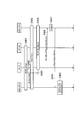
- FIG. 10 is a sequence diagram for explaining the operation (C-3) according to the embodiment.
- Steps S701, S703, and S704 correspond to steps S201, S203, and S204.
- Step S702 corresponds to step S502.
- step S705 the radio base station 100-2 transmits to the access point 200 a Re-offload indicator indicating that the radio terminal 10 has executed a re-offload process from the radio LAN to the radio base station 100.
- step S706 the access point 200 stops the UE stay timer in response to reception of the Re-offload indicator from the radio base station 100-2.
- Step S707 corresponds to step S606.
- step S708 when it is determined that the ping-pong phenomenon has occurred, the access point 200 transmits a ping-pong indicator to the radio base station 100-1 that is the source base station of the radio terminal 10.
- the access point 200 may transmit a stay time indicator to the radio base station 100-1 instead of the ping-pong indicator.
- the ping-pong indicator may indicate a simple ping-pong phenomenon.
- Step S709 corresponds to step S208.
- the radio base station 100 measures the stay time of the wireless LAN.
- the radio base station 100 includes a control unit having a UE stay timer. Thereby, since the radio base station 100 can grasp the stay time of the wireless LAN of the wireless terminal 10, it can grasp whether or not the ping-pong phenomenon has occurred. As a result, the radio base station 100 can appropriately set the determination parameter.
- the wireless terminal 10 measures the staying time of the wireless LAN.
- the radio terminal 10 includes a control unit having a UE stay timer and a transmission unit that transmits a message (Re-offload indicator / ping-pong indicator) based on the measurement result of the UE stay timer.
- the access point 200 measures the staying time of the wireless LAN.
- the access point 200 includes a control unit (for example, a processor) having a UE stay timer, and a transmission unit (for example, a network interface / Wireless transceiver).
- the radio base station 100 includes a receiving unit that receives a message indicating the measurement result of the UE stay timer. Accordingly, the radio base station 100 can grasp whether or not the ping-pong phenomenon has occurred by receiving the message. As a result, the radio base station 100 can appropriately set the determination parameter.
- the wireless base station 100 switches the standby destination or connection destination from the wireless LAN to the mobile communication network after the wireless terminal 10 switches the standby destination or connection destination from the mobile communication network to the wireless LAN,
- a parameter that is referred to when the wireless terminal 10 determines whether to switch a standby destination or a connection destination to the wireless LAN from the mobile communication network To decide.
- the wireless terminal 10 that has switched the standby destination or connection destination to the wireless LAN switches the standby destination or connection destination to the mobile communication network and detects the occurrence of the ping-pong phenomenon
- Determining whether or not the wireless terminal switches the standby or connection destination from the mobile communication network to the wireless LAN, and / or determining whether or not to switch the standby or connection destination from the wireless LAN to the mobile communication network The determination parameter to be referred to is determined.
- the radio base station 100 can appropriately set the determination parameter so that the ping-pong phenomenon does not occur.
- the above-described operation may be performed when cell (re) selection is performed instead of the handover procedure. That is, the offload process may be executed when the wireless terminal 10 is in an idle state.
- the radio base station 100 may transmit the setting information (Configuration) related to the UE stay timer to the radio terminal 10 by SIB or individual signal (dedicated signaling).
- the radio base station 100 may transmit the setting information to the radio terminal 10 when the RRC connection is established (or when the RRC connection is established).
- the radio terminal 10 can start the UE stay timer based on the setting information.
- the setting information may include information specifying information to be included in the Re-offload indicator or the ping-pong indicator. Based on the setting information, the wireless terminal 10 determines information to be included in the Re-offload indicator or the ping-pong indicator. Further, the setting information may specify a timing for separately transmitting information that is not included in the Re-offload indicator or the ping-pong indicator.
- the radio terminal 10 may transmit the UE measurement report and / or the re-offload reason to the radio base station 100 separately from the Re-offload indicator or the ping-pong indicator.
- the radio terminal 10 may transmit a UE measurement report or the like when an RRC connection with the radio base station 100 is established (for example, when a re-offload process is performed).
- the radio terminal 10 may transmit a UE measurement report or the like based on a request from the radio base station 100.
- the radio base station 100 transmits the request to the radio terminal 10. May be.
- the radio base station 100 may transmit the request by a terminal information procedure (UE Information Procedure).
- UE Information Procedure UE Information Procedure
- the radio base station 100 receives the UE measurement report and / or the re-offload reason from the radio terminal 10 to determine the determination parameter. Optimization can be performed.
- the radio terminal 10 may transmit a UE measurement report to the radio base station 100 together with a measurement result of MDT (Minimization of Drive Test).
- MDT Measurement of Drive Test
- a wireless terminal configured to perform MDT measures a received signal state and reports measurement data including information on the result of the measurement and position information at the time of measurement to the mobile communication network (wireless base station 100). To do.
- the MDT that is performed while the wireless terminal is performing communication is referred to as an immediate report type (Immediate MDT), and the MDT that is performed while the wireless terminal is waiting is referred to as a recordable type (Logged MDT).
- the radio terminal 10 can transmit the UE measurement report to the radio base station 100 together with either the immediate report type MDT or the record type MDT report.
- the radio base station 100 transmits setting information (Configuration) related to measurement of reception quality and / or reception strength in the wireless LAN, which is measured while staying in the wireless LAN, to the wireless terminal 10 by SIB or individual signal (dedicated signaling). May be sent to.
- the setting information includes information specifying a measurement reporting method, a measurement cycle, a frequency to be measured, and area information (for example, Tracking Area) including the measurement target.
- the radio base station 100 may determine the access point 200 to be offloaded based on the UE measurement report. For example, when there is an area where the reception strength of the predetermined access point 200 is low, the predetermined access point 200 may be excluded from the offload target in the area.
- a program for causing a computer to execute each process performed by either the wireless terminal 10 or the wireless base station 100 may be provided.
- the program may be recorded on a computer readable medium. If a computer-readable medium is used, a program can be installed in the computer.
- the computer-readable medium on which the program is recorded may be a non-transitory recording medium.
- the non-transitory recording medium is not particularly limited, but may be a recording medium such as a CD-ROM or a DVD-ROM.
- a chip configured by a memory that stores a program for executing each process performed by either the radio terminal 10 or the radio base station 100 and a processor that executes the program stored in the memory may be provided. .
- LTE is exemplified as the mobile communication network.
- the mobile communication network may be a network provided by a communication carrier. Therefore, the mobile communication network may be a UMTS (Universal Mobile Telecommunications System) or GSM (registered trademark).
- UMTS Universal Mobile Telecommunications System
- GSM registered trademark
- Table 1 gives an overview of RAN auxiliary parameters along with some categories and possible solutions for the eNB to set parameters with appropriate values. It should be noted that the OAM that provides the parameters (at least initially) is the baseline, but is omitted in Table 1.
- RSRP and RSRQ thresholds are used to optimize UE throughput and cell load. It is assumed that these thresholds are determined based on the load status of the base station itself.
- the RSRP and RSRQ thresholds may be determined by the base station's own conditions.
- thresholds can be used for BSS load, WAN metric and beacon RSSI used to evaluate throughput and / or load status in WLAN. These thresholds are used for very similar purposes as the RSRP and RSRQ thresholds, especially for optimizing UE throughput before and after traffic steering. Thus, the solution created to estimate the UE throughput in the WLAN may be reused for the determination of these thresholds.
- BSS load, WAN metric, and beacon RSSI thresholds can be determined by the solution created for the assessment of UE throughput in WLAN.
- RAN auxiliary parameters for throughput and load optimization may be automatically determined using existing information or generated solutions.
- the RAN auxiliary parameter has a Tsteering WLAN , which is a timer similar to the existing time-to-trigger (TTT) for E-UTRAN measurement, and the RAN auxiliary parameter can be used for mobility purposes. It is a common recognition. If the evaluation meets criteria based on thresholds for RSRP, RSRQ, BSS load, WAN metric, and beacon RSSI during a Tsteering WLAN that can be tuned between 0 and 7, the UE is the minimum required in the Rel-12 mechanism. It should be noted that while deciding to notify a higher layer of a traffic steering opportunity, the timer value must be long enough to allow frequent changes in the access network to be avoided. It was discussed.
- the most appropriate threshold to set for the Tsteering WLAN will differ according to different deployments. Therefore, it should be optimized for practical deployment.
- the current use case in MRJC is not able to determine the threshold because it immediately evaluates UE throughput in WLAN, so at this point the threshold has other options to set along with the fixed value provided by OAM. No. Considering that a large amount of WLANAP is being deployed daily, the problem is how to maintain an optimal threshold that follows changes in WLAN radio conditions. Therefore, the problem should be solved by an autonomous mechanism to update the threshold, ie MRO with WLAN.
- Proposal 1 It should be agreed to capture the optimization of mobility robustness with WLAN as a new use case.
- WLAN identifiers ie AP BSSID, ESSID and HESSID
- some companies are also interested in autonomous collection mechanisms, eg ANR with WLAN.
- Table 1 is a table for explaining the RAN auxiliary parameters. It should be noted that the OAM that provides the parameters (at least initially) is the baseline, but is omitted in Table 1.
- Tsteering WLAN RAN auxiliary parameter adjustment for mobility robustness
- Tsteering WLAN it is essential for Tsteering WLAN to optimize mobility robustness.
- Tsteering WLAN should be set to the minimum value (0 [s]), but mobility problems like ping-pong steering may occur. Therefore, to provide a better user experience, Tsteering WLAN needs to be configured with a balance between off-road efficiency and ping-pong avoidance.
- the threshold for radio situation assessment has hysteresis between in-and out-of-conditions, and the RAN auxiliary parameter also has two thresholds for such purposes.
- the hysteresis of the RSRP threshold is displayed as (Thresh ServingOffloadWLAN, HighP- Thresh ServingOffloadWLAN, LowP ) [dB].
- the hysteresis set together with the radio condition related RAN auxiliary parameters affects network performance in conjunction with UE mobility.
- Proposal 2 If Proposal 1 is acceptable, it should be agreed that the MRO with WLAN consider Tsteering WLAN optimization and / or threshold hysteresis for RSRP, RSRQ and Beacon RSSI.
- Proposal 3 A method for detecting throughput degradation before / after traffic steering should be considered.
- ping-pong avoidance Another point to consider is ping-pong avoidance. For example, if the RAN auxiliary parameter for traffic steering to the WLAN and the RAN auxiliary parameter for traffic steering from the WLAN are not sufficiently adjusted, ie, the wrong hysteresis is set, the UE It may be decided to immediately return traffic to the WLAN after traffic steering to UTRAN. Since traffic steering is more delayed than HO, such ping-pong steering between E-UTRAN and WLAN may result in a more degraded user experience than ping-pong between E-UTRAN cells. is there. Therefore, a method for detecting ping-pong steering should be considered.
- Proposal 4 A method for detecting ping-pong steering between E-UTRAN and WLAN should be considered.
Abstract
Description
従来の技術では、無線端末が移動通信網から無線LANに待ち受け先又は接続先を切り替える切替処理(オフロード処理)及び同一の無線端末が無線LANから移動通信網に待ち受け先又は接続先を切り替える切替処理(リオフロード処理)を繰り返す現象(以下、ピンポン現象)が懸念される。 [Outline of Embodiment]
In the conventional technology, switching processing (offload processing) in which a wireless terminal switches a standby destination or connection destination from a mobile communication network to a wireless LAN, and switching in which the same wireless terminal switches a standby destination or connection destination from the wireless LAN to the mobile communication network. There is a concern about a phenomenon (hereinafter referred to as ping-pong phenomenon) that repeats the process (re-offload process).
(通信システム)
以下において、第1実施形態に係る通信システムについて説明する。図1は、第1実施形態に係る通信システム1を示す図である。 [First Embodiment]
(Communications system)
Hereinafter, a communication system according to the first embodiment will be described. FIG. 1 is a diagram illustrating a communication system 1 according to the first embodiment.
第1実施形態において、無線端末が移動通信網と無線LANとの間で待ち受け先又は接続先を切り替える切替処理(例えば、ネットワークセレクション及びトラフィックステアリング)を行う方法について説明する。RRCコネクティッド状態又はRRCアイドル状態の無線端末10は、移動通信網(セルラ通信ネットワーク)及び無線LAN(WLAN通信ネットワーク)のうちトラフィックを送受信するネットワークを選択するために切り替える処理を行う。具体的には、移動通信網側の第1情報が第1条件を満たしており、かつ、無線LAN側の第2情報が第2条件を満たしている状態が所定期間に亘って継続する場合に、切替処理(例えば、ネットワークセレクション及びトラフィックステアリング)が実行される。 (Applicable scene)
In the first embodiment, a method for performing a switching process (for example, network selection and traffic steering) in which a wireless terminal switches a standby destination or a connection destination between a mobile communication network and a wireless LAN will be described. The
無線端末が移動通信網から無線LANに対して待ち受け先又は接続先を切り替える第1条件は、例えば、以下の条件(1a)又は(1b)のいずれかが満たされることである。但し、第1条件は、以下の条件(1a)~(1b)の全てが満たされることであってもよい。 (Switching process from mobile communication network to wireless LAN)
The first condition for the wireless terminal to switch the standby destination or the connection destination from the mobile communication network to the wireless LAN is, for example, that either of the following conditions (1a) or (1b) is satisfied. However, the first condition may be that all of the following conditions (1a) to (1b) are satisfied.
(1b)RSRQmeas<ThreshServingOffloadWLAN,LowQ (1a) RSRPmeas <Thresh ServingOffloadWLAN, LowP
(1b) RSRQmeas <Thresh ServingOffloadWLAN, LowQ
(1d)BackhaulRateDlWLAN>ThreshBackhRateDLWLAN,High
(1e)BackhaulRateUlWLAN>ThreshBackhRateULWLAN,High
(1f)RSSI>ThreshBEACONSRSSI,High (1c) ChannelUtilization WLAN <Thresh ChUtilWLAN, Low
(1d) BackhaulRateDlWLAN> Thresh BackRateDLWLAN, High
(1e) BackhaulRateUlWLAN> Thresh BackRateULWLAN, High
(1f) RSSI> Thresh BEACONSRSSI, High
無線端末が無線LANから移動通信網に対して待ち受け先又は接続先を切り替える第1条件は、例えば、以下の条件(2a)及び(2b)が満たされることである。但し、第1条件は、以下の条件(2a)又は(2b)のいずれかが満たされることであってもよい。 (Switching process from wireless LAN to mobile communication network)
The first condition for the wireless terminal to switch the standby destination or connection destination from the wireless LAN to the mobile communication network is, for example, that the following conditions (2a) and (2b) are satisfied. However, the first condition may be that either of the following conditions (2a) or (2b) is satisfied.
(2b)RSRQmeas>ThreshServingOffloadWLAN,HighQ (2a) RSRPmeas> Thresh ServingOffloadWLAN, HighP
(2b) RSRQmeas> Thresh ServingOffloadWLAN, HighQ
(2d)BackhaulRateDlWLAN<ThreshBackhRateDLWLAN,Low
(2e)BackhaulRateUlWLAN<ThreshBackhRateULWLAN,Low
(2f)RSSI<ThreshBEACONSRSSI,Low (2c) ChannelUtilization WLAN> Thresh ChutilWLAN, High
(2d) BackhaulRateDlWLAN <Thresh BackRateDLWLAN, Low
(2e) BackhaulRateULWLAN <Thresh BackRateULWLAN, Low
(2f) RSSI <Thresh BEACONSRSSI, Low
以下において、第1実施形態に係る無線端末について説明する。図2は、第1実施形態に係る無線端末10を示すブロック図である。 (Wireless terminal)
Hereinafter, the wireless terminal according to the first embodiment will be described. FIG. 2 is a block diagram showing the
以下において、第1実施形態に係る無線基地局について説明する。図3は、第1実施形態に係る無線基地局100を示すブロック図である。 (Radio base station)
Hereinafter, the radio base station according to the first embodiment will be described. FIG. 3 is a block diagram showing the
以下において、切替処理の判定について、移動通信網から無線LANに対する切替処理を例に挙げて説明する。 (Determination of switching process)
In the following, the determination of the switching process will be described by taking the switching process from the mobile communication network to the wireless LAN as an example.
次に、実施形態に係る動作について説明する。具体的には、ピンポン現象を抑制するために、判定パラメータを最適化するための情報を取得する動作について説明する。 (Operation according to the embodiment)
Next, operations according to the embodiment will be described. Specifically, an operation for acquiring information for optimizing the determination parameter in order to suppress the ping-pong phenomenon will be described.
無線基地局100が、無線LANに無線端末10が滞在していた滞在時間を計測するUE滞在タイマ(UE stay timer)を有するケースについて説明する。 (A)
A case where the
・eNB識別子(E-UTRAN CGI(Source cell/Target cell))
・WLAN識別子(WLAN ID)
・UE識別子(UE ID) -Message type (Message Type)
ENB identifier (E-UTRAN CGI (Source cell / Target cell))
WLAN identifier (WLAN ID)
-UE identifier (UE ID)
次に、無線端末10が、UE滞在タイマを有するケースについて説明する。 (B)
Next, a case where the
・eNB識別子(E-UTRAN CGI(Source cell/Target cell))
・WLAN識別子(WLAN ID)
・UE識別子(UE ID)
・WLAN滞在時間(WLANStayTimer)
・オフロードトラフィック(OffloadTraffic)
・リオフロード理由(Re-offloadCause)
・ユーザプリファレンス(UserPreference)
・UE測定報告(UE measurementReport) -Message type (Message Type)
ENB identifier (E-UTRAN CGI (Source cell / Target cell))
WLAN identifier (WLAN ID)
-UE identifier (UE ID)
・ WLAN stay time (WLANStayTimer)
・ Offload traffic (OffloadTraffic)
・ Re-offload reason (Re-offloadCause)
・ User Preferences (UserPreference)
UE measurement report (UE measurementReport)
次に、アクセスポイント200が、UE滞在タイマを有するケースについて説明する。 (C)
Next, a case where the
・eNB識別子(E-UTRAN CGI(Source cell/Target cell))
・WLAN識別子(WLAN ID)
・UE識別子(UE ID)
・WLAN滞在時間(WLANStayTimer)
・オフロードトラフィック(OffloadTraffic) -Message type (Message Type)
ENB identifier (E-UTRAN CGI (Source cell / Target cell))
WLAN identifier (WLAN ID)
-UE identifier (UE ID)
・ WLAN stay time (WLANStayTimer)
・ Offload traffic (OffloadTraffic)
本実施形態では、無線基地局100は、無線LANの滞在時間を計測する。言い換えると、無線基地局100は、UE滞在タイマを有する制御部を備える。これにより、無線基地局100は、無線端末10の無線LANの滞在時間が把握できるため、ピンポン現象が発生しているか否かを把握できる。その結果、無線基地局100は、判定パラメータを適切に設定することができる。 (Summary)
In the present embodiment, the
本出願の内容を上述した実施形態によって説明したが、この開示の一部をなす論述及び図面は、本出願の内容を限定するものであると理解すべきではない。この開示から当業者には様々な代替実施形態、実施例及び運用技術が明らかとなろう。 [Other Embodiments]
Although the contents of the present application have been described by using the above-described embodiments, it should not be understood that the descriptions and drawings constituting a part of this disclosure limit the contents of the present application. From this disclosure, various alternative embodiments, examples and operational techniques will be apparent to those skilled in the art.
以下において、本実施形態の付記事項について説明する。 [Appendix]
In the following, supplementary items of the present embodiment will be described.
この付記では、RANアシスタントパラメータを最適化するために、WLANを伴うMRO(Mobility Robustness Optimization)の必要性について説明する。 (1) Introduction This supplementary note describes the necessity of MRO (Mobility Robustness Optimization) with WLAN to optimize the RAN assistant parameters.
(2.1)WLANを伴う協調の更なるユースケースの必要性
RAN補助パラメータ(判定パラメータ)は、E-UTRANとWLANとの間のトラフィックステアリングの決定のためにUEにおいて使用される。RAN補助パラメータは、eNBによって設定される。同メカニズムは、UTRANのために導入されたが、説明を簡単にするために、次の考察は、E-UTRANのためのRAN補助パラメータを前提とする。 (2) Description (2.1) Need for further use case of cooperation with WLAN RAN auxiliary parameter (decision parameter) is used in UE for traffic steering decision between E-UTRAN and WLAN The The RAN auxiliary parameter is set by the eNB. Although the same mechanism was introduced for UTRAN, for the sake of simplicity, the following discussion assumes RAN auxiliary parameters for E-UTRAN.

UEは、UEのモビリティにより引き起こされる3GPPとWLANとの間のピンポントラフィックステアリングが原因でQoEに苦しむ可能性がある。さらに、UEモビリティも、スループットの劣化につながる不正確なトラフィックステアリングを引き起こす可能性がある。現在、そのような劣化を避けるための情報がRANには存在しない。3GPPとWLANとの間で(もしあれば)情報を交換することを調査し、WLANデプロイメントを考慮したモビリティロバスト性最適化メカニズムを(もしあれば)拡張することが有益である。 (2.2) Optimization of mobility robustness with WLAN UE may suffer from QoE due to ping-pong traffic steering between 3GPP and WLAN caused by UE mobility. Furthermore, UE mobility can also cause inaccurate traffic steering leading to throughput degradation. Currently, there is no information in the RAN to avoid such degradation. It would be beneficial to investigate exchanging information (if any) between 3GPP and WLAN, and to extend the mobility robustness optimization mechanism (if any) considering WLAN deployment.
問題2:早すぎるトラフィックステアリング及び/又は遅すぎるトラフィックステアリングを回避する方法 Problem 1: How to avoid ping-pong traffic steering Problem 2: How to avoid too early traffic steering and / or too late traffic steering
2.1章で述べた通り、TsteeringWLANは、モビリティロバスト性を最適化することが本質である。明らかに、オフロード効率のみを考慮した場合、TsteeringWLANを最小値(0[s])に設定すべきであるが、ピンポンステアリングのようなモビリティ問題が生じる可能性がある。従って、より良いユーザ体験を提供するために、オフロード効率とピンポン回避との間のバランス値で、TsteeringWLANを設定する必要があります。 (2.3) RAN auxiliary parameter adjustment for mobility robustness As described in section 2.1, it is essential for Tsteering WLAN to optimize mobility robustness. Obviously, when considering only off-road efficiency, Tsteering WLAN should be set to the minimum value (0 [s]), but mobility problems like ping-pong steering may occur. Therefore, to provide a better user experience, Tsteering WLAN needs to be configured with a balance between off-road efficiency and ping-pong avoidance.
E-UTRANのための既存のMROは、早すぎるHO(Too Early HO)、遅すぎるHO(Too Late HO)及び間違ったセルへのHO(HO to Wrong Cell)を検出するために用いることができるRLFインディケーション(RLF INDICATION)及びハンドオーバレポート(HANDOVER REPORT)を有する。WLANを伴うMROを考慮して、既存のMROと異なる点は、RLFと関係がなく、すなわち、RLFは、WLANから/へのトラフィックステアリング失敗したかどうかに基づかない。 (2.4) Possible information for MRO with WLAN Existing MRO for E-UTRAN is too early HO (Too Early HO), too late HO (Too Late HO) and wrong cell HO It has a RLF indication (RLF INDICATION) and a handover report (HANDOVER REPORT) that can be used to detect (HO to Wong Cell). Considering MRO with WLAN, the difference from existing MRO is not related to RLF, ie RLF is not based on whether or not traffic steering failed from / to WLAN.
この付記では、RAN補助パラメータを最適化するためにWLANを伴うMROの必要性を説明した。 (3) Conclusion This appendix explained the need for MRO with WLAN to optimize RAN auxiliary parameters.
Claims (17)
- 移動通信網を構成する無線基地局であって、
無線LANに無線端末が滞在していた滞在時間を計測するコントローラを備え、
前記滞在時間は、前記無線端末が前記移動通信網から前記無線LANへ待ち受け先又は接続先を切り替える第1処理を行ってから、前記無線端末が前記無線LANから前記移動通信網へ待ち受け先又は接続先を切り替える第2処理を行うまでの時間であることを特徴とする無線基地局。 A wireless base station constituting a mobile communication network,
It has a controller that measures the stay time that the wireless terminal stays in the wireless LAN,
The staying time is determined when the wireless terminal performs a first process of switching a standby destination or connection destination from the mobile communication network to the wireless LAN, and then the wireless terminal waits or connects from the wireless LAN to the mobile communication network. A radio base station characterized in that it is a time until the second processing for switching the destination is performed. - 前記第1処理は、前記無線端末が自己の無線基地局から前記無線LANへ待ち受け先又は接続先を切り替える処理であり、
前記第2処理は、前記無線端末が前記無線LANから自己の無線基地局へ待ち受け先又は接続先を切り替える処理であることを特徴とする請求項1に記載の無線基地局。 The first process is a process in which the wireless terminal switches a standby destination or a connection destination from its own wireless base station to the wireless LAN,
The radio base station according to claim 1, wherein the second process is a process in which the radio terminal switches a standby destination or a connection destination from the radio LAN to its own radio base station. - 前記第1処理は、前記無線端末が自己の無線基地局から前記無線LANへ待ち受け先又は接続先を切り替える処理であり、
前記第2処理は、前記無線端末が前記無線LANから自己の無線基地局とは異なる他の無線基地局へ待ち受け先又は接続先を切り替える処理であることを特徴とする請求項1に記載の無線基地局。 The first process is a process in which the wireless terminal switches a standby destination or a connection destination from its own wireless base station to the wireless LAN,
2. The wireless communication according to claim 1, wherein the second process is a process in which the wireless terminal switches a standby destination or a connection destination from the wireless LAN to another wireless base station different from its own wireless base station. base station. - 前記コントローラは、前記無線端末が前記第2処理を実行したことを示す情報を前記他の無線基地局から受信することによって、前記無線端末が前記第2処理を行ったことを検出することを特徴とする請求項3に記載の無線基地局。 The controller detects that the wireless terminal has performed the second processing by receiving information indicating that the wireless terminal has performed the second processing from the other wireless base station. The radio base station according to claim 3.
- 前記コントローラは、前記無線端末が前記第2処理を実行したことを示す情報を前記無線LANを構成するエンティティから受信することによって、前記無線端末が前記第2処理を行ったことを検出することを特徴とする請求項3に記載の無線基地局。 The controller detects that the wireless terminal has performed the second process by receiving information indicating that the wireless terminal has performed the second process from an entity constituting the wireless LAN. The radio base station according to claim 3, wherein:
- 前記コントローラは、前記滞在時間に基づいて、パラメータを決定し、
前記パラメータは、前記無線端末が前記移動通信網から前記無線LANに対して待ち受け先又は接続先を切り替えるか否かを判定することに用いるパラメータであることを特徴とする請求項1に記載の無線基地局。 The controller determines a parameter based on the stay time,
The wireless parameter according to claim 1, wherein the parameter is a parameter used for determining whether the wireless terminal switches a standby destination or a connection destination for the wireless LAN from the mobile communication network. base station. - 無線LANに滞在していた滞在時間を計測するコントローラと、
移動通信網を構成する無線基地局に対して、前記滞在時間の計測結果に基づくメッセージを送信するトランスミッタとを備え、
前記滞在時間は、前記移動通信網から前記無線LANへ待ち受け先又は接続先を切り替える第1処理を行ってから、前記無線LANから前記移動通信網へ待ち受け先又は接続先を切り替える第2処理を行うまでの時間であることを特徴とする無線端末。 A controller for measuring the staying time spent in the wireless LAN;
A transmitter for transmitting a message based on the measurement result of the stay time to a radio base station constituting a mobile communication network,
For the stay time, after performing a first process of switching a standby destination or a connection destination from the mobile communication network to the wireless LAN, a second process of switching a standby destination or a connection destination from the wireless LAN to the mobile communication network is performed. A wireless terminal characterized by the time until. - 前記メッセージは、前記第1処理を行ってから前記第2処理を行うまでの時間が所定時間内であることを示すメッセージであることを特徴とする請求項7に記載の無線端末。 The wireless terminal according to claim 7, wherein the message is a message indicating that a time period from the first process to the second process being within a predetermined time.
- 前記メッセージは、前記滞在時間の値を示すメッセージであることを特徴とする請求項7に記載の無線端末。 The wireless terminal according to claim 7, wherein the message is a message indicating the value of the staying time.
- 前記メッセージは、前記無線端末が前記第1処理を行ってから前記第2処理を行ったこと及び所定の現象が発生したことを示す通知であることを特徴とする請求項7に記載の無線端末。 8. The wireless terminal according to claim 7, wherein the message is a notification indicating that the wireless terminal has performed the second process after performing the first process and that a predetermined phenomenon has occurred. .
- 無線LANに接続されていた無線端末又は前記無線LANを構成するエンティティから、前記無線LANに前記無線端末が滞在していた滞在時間の計測結果に基づくメッセージを受信するレシーバを備え、
前記滞在時間は、前記無線端末が前記移動通信網から前記無線LANに対して待ち受け先又は接続先を切り替える第1処理を行ってから、前記無線端末が前記無線LANから前記移動通信網に対して待ち受け先又は接続先を切り替える第2処理を行うまでの時間であることを特徴とする無線基地局。 A receiver that receives a message based on a measurement result of a stay time in which the wireless terminal stayed in the wireless LAN from a wireless terminal connected to the wireless LAN or an entity constituting the wireless LAN;
The staying time is determined when the wireless terminal performs a first process of switching a standby destination or a connection destination for the wireless LAN from the mobile communication network, and then the wireless terminal transmits the wireless LAN to the mobile communication network. A wireless base station, characterized in that it is a time until the second processing for switching a standby destination or a connection destination. - 前記メッセージは、前記無線端末が前記第1処理を行ってから前記第2処理を行うまでの時間が一定期間内であることを示すメッセージであることを特徴とする請求項11に記載の無線基地局。 The radio base station according to claim 11, wherein the message is a message indicating that a time from when the radio terminal performs the first process to when the second process is performed is within a certain period. Bureau.
- 前記メッセージは、前記滞在時間を示すメッセージであることを特徴とする請求項11に記載の無線基地局。 The radio base station according to claim 11, wherein the message is a message indicating the staying time.
- 前記メッセージは、前記無線端末が前記第1処理を行ってから前記第2処理を行ったこと及び所定の現象が発生したことを示す通知であることを特徴とする請求項11に記載の無線基地局。 The radio base station according to claim 11, wherein the message is a notification indicating that the radio terminal has performed the second process after performing the first process and that a predetermined phenomenon has occurred. Bureau.
- 移動通信網を構成する無線基地局であって、
無線端末が前記移動通信網から無線LANへ待ち受け先又は接続先を切り替えてから前記無線LANから前記移動通信網へ待ち受け先又は接続先を切り替えたこと及び所定の現象が発生したことを検出した場合に、前記無線端末が前記移動通信網と前記無線LANとの間で待ち受け先又は接続先を切り替えるか否かを判定することに使用するパラメータを決定するコントローラを備えることを特徴とする無線基地局。 A wireless base station constituting a mobile communication network,
When it is detected that the wireless terminal has switched the standby destination or connection destination from the mobile communication network to the wireless LAN and then switched from the wireless LAN to the mobile communication network and that a predetermined phenomenon has occurred. And a controller for determining a parameter used for determining whether or not the wireless terminal switches a standby destination or a connection destination between the mobile communication network and the wireless LAN. . - 前記無線LANを構成するエンティティ又は前記無線端末から前記所定の現象が発生したことを示す通知を受信するレシーバをさらに備え、
前記コントローラは、前記レシーバが前記所定の現象が発生したことを示す通知を受信することで、前記所定の現象が発生したことを検出することを特徴とする請求項15に記載の無線基地局。 A receiver for receiving a notification indicating that the predetermined phenomenon has occurred from an entity constituting the wireless LAN or the wireless terminal;
16. The radio base station according to claim 15, wherein the controller detects that the predetermined phenomenon has occurred by receiving a notification indicating that the predetermined phenomenon has occurred. - 前記所定の現象は、所定条件を満たす現象であって、
前記所定条件は、前記無線端末が前記移動通信網から前記無線LANへ待ち受け先又は接続先を切り替えてから前記無線LANから前記移動通信網へ待ち受け先又は接続先を切り替えるまでに経過した時間が所定時間内であることを含む請求項15に記載の無線基地局。 The predetermined phenomenon is a phenomenon that satisfies a predetermined condition,
The predetermined condition is that a time elapsed from when the wireless terminal switches the standby destination or connection destination from the mobile communication network to the wireless LAN until the standby destination or connection destination is switched from the wireless LAN to the mobile communication network is predetermined. The radio base station according to claim 15, comprising being within time.
Priority Applications (2)
| Application Number | Priority Date | Filing Date | Title |
|---|---|---|---|
| JP2016550350A JP6527527B2 (en) | 2014-09-26 | 2015-09-24 | Wireless base station and wireless terminal |
| US15/511,652 US10341922B2 (en) | 2014-09-26 | 2015-09-24 | Radio base station and radio terminal |
Applications Claiming Priority (2)
| Application Number | Priority Date | Filing Date | Title |
|---|---|---|---|
| US201462056061P | 2014-09-26 | 2014-09-26 | |
| US62/056,061 | 2014-09-26 |
Publications (1)
| Publication Number | Publication Date |
|---|---|
| WO2016047672A1 true WO2016047672A1 (en) | 2016-03-31 |
Family
ID=55581195
Family Applications (1)
| Application Number | Title | Priority Date | Filing Date |
|---|---|---|---|
| PCT/JP2015/076891 WO2016047672A1 (en) | 2014-09-26 | 2015-09-24 | Wireless base station and wireless terminal |
Country Status (3)
| Country | Link |
|---|---|
| US (1) | US10341922B2 (en) |
| JP (1) | JP6527527B2 (en) |
| WO (1) | WO2016047672A1 (en) |
Families Citing this family (4)
| Publication number | Priority date | Publication date | Assignee | Title |
|---|---|---|---|---|
| EP3780707A4 (en) * | 2018-04-23 | 2021-12-01 | Beijing Xiaomi Mobile Software Co., Ltd. | Method and device for configuring and reporting measurement, base station, and user equipment |
| CN112703764B (en) * | 2018-09-19 | 2024-03-05 | 瑞典爱立信有限公司 | Network node and method in a wireless communication network |
| US11696171B2 (en) | 2020-08-31 | 2023-07-04 | Arris Enterprises Llc | Mitigation of excessive client steering attempts in multiple access point networks |
| US11706677B2 (en) * | 2020-10-01 | 2023-07-18 | T-Mobile Usa, Inc. | Handover processing between communication networks |
Citations (2)
| Publication number | Priority date | Publication date | Assignee | Title |
|---|---|---|---|---|
| JP2012514949A (en) * | 2009-01-06 | 2012-06-28 | クゥアルコム・インコーポレイテッド | Adaptation of handover parameters |
| JP2013535904A (en) * | 2010-08-13 | 2013-09-12 | 華為技術有限公司 | Method for providing information, mobile station apparatus, base station apparatus, and communication apparatus |
Family Cites Families (2)
| Publication number | Priority date | Publication date | Assignee | Title |
|---|---|---|---|---|
| WO2013020604A1 (en) * | 2011-08-11 | 2013-02-14 | Nokia Siemens Networks Oy | User equipment short stay report |
| EP3178260B1 (en) * | 2014-08-08 | 2023-09-20 | Nokia Solutions and Networks Oy | Methods of controlling user equipment communication with a network and corresponding apparatuses and computer program product |
-
2015
- 2015-09-24 WO PCT/JP2015/076891 patent/WO2016047672A1/en active Application Filing
- 2015-09-24 US US15/511,652 patent/US10341922B2/en active Active
- 2015-09-24 JP JP2016550350A patent/JP6527527B2/en active Active
Patent Citations (2)
| Publication number | Priority date | Publication date | Assignee | Title |
|---|---|---|---|---|
| JP2012514949A (en) * | 2009-01-06 | 2012-06-28 | クゥアルコム・インコーポレイテッド | Adaptation of handover parameters |
| JP2013535904A (en) * | 2010-08-13 | 2013-09-12 | 華為技術有限公司 | Method for providing information, mobile station apparatus, base station apparatus, and communication apparatus |
Also Published As
| Publication number | Publication date |
|---|---|
| US20170303179A1 (en) | 2017-10-19 |
| JP6527527B2 (en) | 2019-06-05 |
| US10341922B2 (en) | 2019-07-02 |
| JPWO2016047672A1 (en) | 2017-07-20 |
Similar Documents
| Publication | Publication Date | Title |
|---|---|---|
| US10321382B2 (en) | Mobility and/or access selection between cells | |
| KR102071483B1 (en) | Systems, methods and devices for traffic offloading | |
| EP2740293B1 (en) | Improved handover robustness in cellular radio communications | |
| US8903399B2 (en) | Methods and network nodes for detecting short stay handover | |
| TWI442793B (en) | Method of reporting measurement report events | |
| JP6467543B2 (en) | COMMUNICATION SYSTEM, USER TERMINAL, PROCESSOR AND COMMUNICATION CONTROL METHOD | |
| US9973951B1 (en) | Use of UE-capability reporting to control UE service | |
| WO2014177003A1 (en) | Measurement configuration processing method and device | |
| JP6527527B2 (en) | Wireless base station and wireless terminal | |
| JP5981051B1 (en) | Wireless terminal | |
| JP6153673B2 (en) | Base station and communication device | |
| US20170339613A1 (en) | Base station, apparatus, and radio terminal | |
| WO2014121688A1 (en) | Wlan load determination method, device and system | |
| US10484924B2 (en) | Core network apparatus, radio terminal, and base station | |
| US20170325150A1 (en) | Base station and processor | |
| JP7019294B2 (en) | Wireless terminal |
Legal Events
| Date | Code | Title | Description |
|---|---|---|---|
| 121 | Ep: the epo has been informed by wipo that ep was designated in this application |
Ref document number: 15845217 Country of ref document: EP Kind code of ref document: A1 |
|
| ENP | Entry into the national phase |
Ref document number: 2016550350 Country of ref document: JP Kind code of ref document: A |
|
| WWE | Wipo information: entry into national phase |
Ref document number: 15511652 Country of ref document: US |
|
| NENP | Non-entry into the national phase |
Ref country code: DE |
|
| 122 | Ep: pct application non-entry in european phase |
Ref document number: 15845217 Country of ref document: EP Kind code of ref document: A1 |