WO2016047369A1 - Sealing structure - Google Patents
Sealing structure Download PDFInfo
- Publication number
- WO2016047369A1 WO2016047369A1 PCT/JP2015/074388 JP2015074388W WO2016047369A1 WO 2016047369 A1 WO2016047369 A1 WO 2016047369A1 JP 2015074388 W JP2015074388 W JP 2015074388W WO 2016047369 A1 WO2016047369 A1 WO 2016047369A1
- Authority
- WO
- WIPO (PCT)
- Prior art keywords
- backup ring
- pressure side
- cut
- ring
- peripheral surface
- Prior art date
Links
Images


Classifications
-
- F—MECHANICAL ENGINEERING; LIGHTING; HEATING; WEAPONS; BLASTING
- F16—ENGINEERING ELEMENTS AND UNITS; GENERAL MEASURES FOR PRODUCING AND MAINTAINING EFFECTIVE FUNCTIONING OF MACHINES OR INSTALLATIONS; THERMAL INSULATION IN GENERAL
- F16J—PISTONS; CYLINDERS; SEALINGS
- F16J15/00—Sealings
- F16J15/16—Sealings between relatively-moving surfaces
- F16J15/166—Sealings between relatively-moving surfaces with means to prevent the extrusion of the packing
-
- F—MECHANICAL ENGINEERING; LIGHTING; HEATING; WEAPONS; BLASTING
- F16—ENGINEERING ELEMENTS AND UNITS; GENERAL MEASURES FOR PRODUCING AND MAINTAINING EFFECTIVE FUNCTIONING OF MACHINES OR INSTALLATIONS; THERMAL INSULATION IN GENERAL
- F16J—PISTONS; CYLINDERS; SEALINGS
- F16J15/00—Sealings
- F16J15/16—Sealings between relatively-moving surfaces
- F16J15/18—Sealings between relatively-moving surfaces with stuffing-boxes for elastic or plastic packings
- F16J15/24—Sealings between relatively-moving surfaces with stuffing-boxes for elastic or plastic packings with radially or tangentially compressed packing
-
- F—MECHANICAL ENGINEERING; LIGHTING; HEATING; WEAPONS; BLASTING
- F16—ENGINEERING ELEMENTS AND UNITS; GENERAL MEASURES FOR PRODUCING AND MAINTAINING EFFECTIVE FUNCTIONING OF MACHINES OR INSTALLATIONS; THERMAL INSULATION IN GENERAL
- F16J—PISTONS; CYLINDERS; SEALINGS
- F16J15/00—Sealings
- F16J15/16—Sealings between relatively-moving surfaces
- F16J15/18—Sealings between relatively-moving surfaces with stuffing-boxes for elastic or plastic packings
-
- F—MECHANICAL ENGINEERING; LIGHTING; HEATING; WEAPONS; BLASTING
- F16—ENGINEERING ELEMENTS AND UNITS; GENERAL MEASURES FOR PRODUCING AND MAINTAINING EFFECTIVE FUNCTIONING OF MACHINES OR INSTALLATIONS; THERMAL INSULATION IN GENERAL
- F16J—PISTONS; CYLINDERS; SEALINGS
- F16J15/00—Sealings
- F16J15/16—Sealings between relatively-moving surfaces
- F16J15/32—Sealings between relatively-moving surfaces with elastic sealings, e.g. O-rings
- F16J15/3268—Mounting of sealing rings
- F16J15/3272—Mounting of sealing rings the rings having a break or opening, e.g. to enable mounting on a shaft otherwise than from a shaft end
-
- F—MECHANICAL ENGINEERING; LIGHTING; HEATING; WEAPONS; BLASTING
- F16—ENGINEERING ELEMENTS AND UNITS; GENERAL MEASURES FOR PRODUCING AND MAINTAINING EFFECTIVE FUNCTIONING OF MACHINES OR INSTALLATIONS; THERMAL INSULATION IN GENERAL
- F16J—PISTONS; CYLINDERS; SEALINGS
- F16J15/00—Sealings
- F16J15/16—Sealings between relatively-moving surfaces
- F16J15/32—Sealings between relatively-moving surfaces with elastic sealings, e.g. O-rings
- F16J15/3284—Sealings between relatively-moving surfaces with elastic sealings, e.g. O-rings characterised by their structure; Selection of materials
-
- F—MECHANICAL ENGINEERING; LIGHTING; HEATING; WEAPONS; BLASTING
- F16—ENGINEERING ELEMENTS AND UNITS; GENERAL MEASURES FOR PRODUCING AND MAINTAINING EFFECTIVE FUNCTIONING OF MACHINES OR INSTALLATIONS; THERMAL INSULATION IN GENERAL
- F16J—PISTONS; CYLINDERS; SEALINGS
- F16J15/00—Sealings
- F16J15/16—Sealings between relatively-moving surfaces
- F16J15/34—Sealings between relatively-moving surfaces with slip-ring pressed against a more or less radial face on one member
- F16J15/3404—Sealings between relatively-moving surfaces with slip-ring pressed against a more or less radial face on one member and characterised by parts or details relating to lubrication, cooling or venting of the seal
- F16J15/3408—Sealings between relatively-moving surfaces with slip-ring pressed against a more or less radial face on one member and characterised by parts or details relating to lubrication, cooling or venting of the seal at least one ring having an uneven slipping surface
- F16J15/3412—Sealings between relatively-moving surfaces with slip-ring pressed against a more or less radial face on one member and characterised by parts or details relating to lubrication, cooling or venting of the seal at least one ring having an uneven slipping surface with cavities
- F16J15/3416—Sealings between relatively-moving surfaces with slip-ring pressed against a more or less radial face on one member and characterised by parts or details relating to lubrication, cooling or venting of the seal at least one ring having an uneven slipping surface with cavities with at least one continuous groove
-
- F—MECHANICAL ENGINEERING; LIGHTING; HEATING; WEAPONS; BLASTING
- F16—ENGINEERING ELEMENTS AND UNITS; GENERAL MEASURES FOR PRODUCING AND MAINTAINING EFFECTIVE FUNCTIONING OF MACHINES OR INSTALLATIONS; THERMAL INSULATION IN GENERAL
- F16J—PISTONS; CYLINDERS; SEALINGS
- F16J15/00—Sealings
- F16J15/002—Sealings comprising at least two sealings in succession
- F16J15/008—Sealings comprising at least two sealings in succession with provision to put out of action at least one sealing; One sealing sealing only on standstill; Emergency or servicing sealings
Definitions
- the present invention relates to a sealing structure including a backup ring.
- a sealing structure in which a resin backup ring is provided adjacent to a rubber-like elastic seal ring on the lower pressure side than the seal ring. According to this sealing structure, it is possible to suppress a part of the seal ring from protruding from the annular groove for mounting the seal ring by the backup ring. Thereby, it can suppress that a seal ring is damaged.
- the backup ring is provided with a cutting portion at one place in the circumferential direction. Therefore, when a part of the seal ring is sandwiched between the cut surfaces in the cut portion, the seal ring may be damaged. Therefore, there is still room for improvement.
- An object of the present invention is to provide a sealing structure that can prevent the seal ring from being damaged due to the backup ring.
- the present invention employs the following means in order to solve the above problems.
- the sealing structure of the present invention is A shaft having an annular groove formed on the outer peripheral surface side; A housing having a shaft hole through which the shaft is inserted; A seal ring made of a rubber-like elastic body that is mounted in the annular groove and seals an annular gap between the shaft and the shaft hole; Adjacent to the seal ring, a resin backup ring mounted on the lower pressure side than the seal ring;
- a sealing structure comprising: On the low pressure side of the groove bottom surface in the annular groove, a tapered surface is provided that expands toward the low pressure side, The inner peripheral surface of the backup ring is configured with a tapered surface that has a taper angle larger than the tapered surface provided on the groove bottom surface and expands toward the low pressure side,
- the backup ring is a sealing structure in which an annular edge portion on the high-pressure side of the inner peripheral surface of the backup ring is disposed at a position where it can slide with respect to a tapered surface provided on the groove bottom surface,
- the backup ring is
- the second cutting lines formed on the low pressure side surface are parallel to each other, and the cutting surface is configured to be inclined with respect to the central axis of the backup ring, and the high pressure side surface of the backup ring and Among the angles formed by the cut surface, the acute angle is set to 15 ° or more and 30 ° or less,
- the backup ring is made of a resin material having a Rockwell hardness of 100 or less, a durometer hardness of 70 or less, and an elastic modulus of 1.0 GPa or less.
- the annular edge portion on the high pressure side of the inner peripheral surface of the backup ring is configured to be slidable with respect to the tapered surface provided on the groove bottom surface of the annular groove. Therefore, since the sliding portion is in (substantially) line contact, the backup ring can move smoothly in the direction of the central axis. Thereby, it is suppressed that a clearance gap is formed between a backup ring and an annular groove, and it can suppress that a part of seal ring protrudes between these.
- the backup ring has a cutting portion at one place in the circumferential direction, it is easy to attach the backup ring to the annular groove. Moreover, since this cutting part is cut
- the angle on the acute side of the angle formed between the high-pressure side surface of the backup ring and the cut surface is set to 15 ° to 30 °.
- the tip portion on the side forming the acute angle is moved to the low pressure side through the cut portion. It will be in a bent state. Therefore, it can suppress that a part of seal ring is pinched by the clearance gap between cut surfaces.
- the backup ring is made of a resin material having a Rockwell hardness of 100 or less, a durometer hardness of 70 or less, and an elastic modulus of 1.0 GPa or less. Thereby, the front-end
- the surface parallel to the central axis and including the second cutting line may be positioned on the outer side in the radial direction from the annular end portion on the high pressure side of the inner peripheral surface of the backup ring.
- the outer peripheral surface of the backup ring is configured with a tapered surface that decreases in diameter toward the low pressure side, and an annular edge portion on the high pressure side of the outer peripheral surface of the backup ring is formed on the inner peripheral surface of the shaft hole of the housing. On the other hand, it is good to be slidable.
- the seal ring can be prevented from being damaged due to the backup ring.
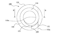
- FIG. 1 is a view of a backup ring according to an embodiment of the present invention as viewed from the high pressure side.
- FIG. 2 is a view of the backup ring according to the embodiment of the present invention as seen from the low pressure side.
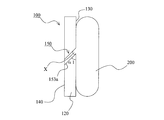
- FIG. 3 is a schematic cross-sectional view of a backup ring according to an embodiment of the present invention.
- FIG. 4 is a schematic cross-sectional view of a sealing structure according to an embodiment of the present invention.
- FIG. 5 is a diagram for explaining the relationship between the angle of the cut surface of the cutting portion provided in the backup ring and the seal ring.
- FIG. 6 is a diagram for explaining the relationship between the angle of the cut surface of the cutting portion provided in the backup ring and the seal ring.
- FIG. 7 is a diagram for explaining how to set the angle of the cut surface of the cutting portion provided in the backup ring.
- the sealing structure according to the present embodiment is a structure in which the annular gap between the shaft and the shaft hole (of the housing) is sealed by a rubber-like elastic seal ring.
- the shaft and the housing are provided concentrically, and these two members may move relatively (at least one of rotation and reciprocation) or may be stationary with respect to each other. .
- these two members are provided concentrically, it is not always necessary to maintain the concentric state, and an eccentric state may occur.
- one in the central axis direction is the high pressure side (H) and the other is the low pressure side (L). However, there may be a state in which a differential pressure is not generated between the pressures on both sides.
- a fluid to be sealed (such as oil) may be sealed on the high pressure side (H), and the air on the low pressure side (L) may be air, or the fluid to be sealed may be sealed on both sides.
- the injector part in a direct-injection engine, the cylinder for construction machines, the cylinder for general machines, and a shock absorber can be mentioned.
- FIG. 4 is a schematic cross-sectional view of the sealing structure according to the embodiment of the present invention, and is a cross-sectional view cut along a plane including the central axis of various members.
- the sealing structure according to the present embodiment is made of a rubber elastic body that seals the shaft 300, the housing 400 having the shaft hole 410 through which the shaft 300 is inserted, and the annular gap between the shaft 300 and the shaft hole 410 ( For example, a seal ring 200 made of NBR) and a resin backup ring 100 adjacent to the seal ring 200 are formed.
- An annular groove 310 is formed on the outer peripheral surface side of the shaft 300.
- the seal ring 200 and the backup ring 100 are attached to the annular groove 310. Further, the seal ring 200 is mounted on the high pressure side (H), and the backup ring 100 is mounted on the low pressure side (L) than the seal ring 200. Further, a tapered surface 311 having a diameter increasing toward the low pressure side (L) is provided on the low pressure side (L) of the groove bottom surface in the annular groove 310. The backup ring 100 is mounted at a position where the tapered surface 311 is provided. The backup ring 100 plays a role of preventing a part of the seal ring 200 from protruding into the gap between the outer peripheral surface of the shaft 300 and the inner peripheral surface of the shaft hole 410 of the housing 400. Note that the seal ring 200 according to the present embodiment is an O-ring having a circular cross-sectional shape.
- FIG. 1 is a view of a backup ring 100 according to an embodiment of the present invention as viewed from the high pressure side (H).
- FIG. 2 is a view of the backup ring 100 according to the embodiment of the present invention as viewed from the low pressure side (L).
- FIG. 3 is a schematic cross-sectional view of the backup ring 100 according to the embodiment of the present invention. 3 corresponds to the AA cross-sectional view in FIG. 1, and corresponds to the BB cross-sectional view in FIG.
- the high-pressure side surface (hereinafter referred to as the high-pressure side surface 130) and the low-pressure side surface (hereinafter referred to as the low-pressure side surface 140) in the backup ring 100 according to the present embodiment are both flat.
- the internal peripheral surface 110 of the backup ring 100 is comprised by the taper surface which diameter-expands toward a low voltage
- the outer peripheral surface 120 of the backup ring 100 is comprised by the taper surface which diameter-reduces toward a low voltage
- the taper angle of the inner peripheral surface 110 of the backup ring 100 is set to be larger than the taper angle of the taper surface 311 provided on the groove bottom surface of the annular groove 310.
- the annular edge portion 110a on the high-pressure side (H) of the inner peripheral surface 110 of the backup ring 100 is slidable with respect to the tapered surface 311 provided on the groove bottom surface ( (See FIG. 4). Therefore, the sliding portion between the backup ring 100 and the annular groove 310 is in (substantially) line contact.
- the outer peripheral surface 120 of the backup ring 100 is configured by a tapered surface that decreases in diameter toward the low pressure side (L).
- the inner peripheral surface of the shaft hole 410 of the housing 400 is a cylindrical surface.
- the backup ring 100 is configured such that the high-pressure side (H) annular end portion 120 a of the outer peripheral surface 120 of the backup ring 100 is slidable with respect to the inner peripheral surface of the shaft hole 410 of the housing 400 ( (See FIG. 4). Therefore, the sliding portion between the backup ring 100 and the shaft hole 410 of the housing 400 is also in (substantially) line contact.
- the angle between the outer peripheral surface 120 and the inner peripheral surface of the shaft hole 410 is designed to be 3 ° (tolerance ⁇ 2 °).
- the backup ring 100 is provided with a cutting portion 150 cut in a planar shape at one place in the circumferential direction.
- the cutting portion 150 is provided so that the backup ring 100 can be easily attached to the annular groove 310.
- a bias cut is employ
- the first cutting line 151 formed on the high pressure side surface 130 and the second cutting line 152 formed on the low pressure side surface 140 of the backup ring 100 are parallel to each other. (See FIGS. 1 and 2). Further, the cutting unit 150 according to the present embodiment is configured such that the cut surface 153 is inclined with respect to the central axis of the backup ring 100 (see FIG. 3).
- FIGS. 5 and 6 are views for explaining the relationship between the angle of the cut surface of the cutting portion provided in the backup ring and the seal ring.
- 5 and 6 are views of the seal ring 200 and the backup ring 100 as seen from the outer peripheral surface side in the use state.
- FIG. 5 shows a case where the angle ⁇ 1 on the acute angle side among the angles formed by the high-pressure side surface 130 of the backup ring 100 and the cut surface 153a is 45 °.
- the rigidity of the tip portion on the side forming the acute angle is relatively high via the cutting portion 150. Therefore, when the seal ring 200 is pressed toward the backup ring 100 side while the cut surfaces of the cutting part 150 are separated from each other, a part X of the seal ring 200 is sandwiched in the gap between the cut surfaces. . As a result, the seal ring 200 is damaged.
- FIG. 6 shows a case where the angle ⁇ 2 on the acute angle side among the angles formed by the high-pressure side surface 130 of the backup ring 100 and the cut surface 153b is 22 °.
- the rigidity of the tip portion on the side forming the acute angle is relatively low via the cutting portion 150. Therefore, when the seal ring 200 is pressed toward the backup ring 100 side while the cut surfaces of the cutting portion 150 are separated from each other, the tip portion on the side forming an acute angle is cut through the cutting portion 150 on the low pressure side ( L). That is, the tip portion is bent in the direction of arrow R in FIG. Therefore, it can suppress that a part of seal ring 200 is pinched by the clearance gap between cut surfaces.
- a dotted line indicates a state where the backup ring 100 is not pressed by the seal ring 200
- a solid line indicates a state where the backup ring 100 is pressed.
- the angle ⁇ 2 on the acute angle side is set to 15 ° or more and 30 ° or less, it is possible to suitably suppress a part of the seal ring 200 from being sandwiched between the gaps between the cut surfaces. It was. Therefore, for example, it is preferable to set the angle ⁇ 2 on the acute angle side to 22 ° (tolerance ⁇ 5 °).
- FIG. 7 is a diagram for explaining how to set the angle of the cutting surface 153 of the cutting unit 150 provided in the backup ring 100.
- a line passing through the center between the first cutting line 151 and the second cutting line 152 and parallel thereto (corresponding to the point L1 in FIG. 7).
- the cutting part 150 is provided so that it may pass along the central axis L0 of the backup ring 100.
- the cut portion 150 is formed so that the cut surface passes through the annular edge portion 110a on the high-pressure side (H) of the inner peripheral surface 110 of the backup ring 100, the first cut line 151 and the second cut are formed.
- the distance from the line 152 is the longest (see the cut surface 153c in FIG. 7).
- the acute angle ⁇ 3 is the smallest.
- the inner diameter of the high-pressure side (H) annular end portion 110a of the inner peripheral surface 110 of the backup ring 100 becomes smaller, the above-mentioned acute angle ⁇ 3 has to be set larger.
- the acute angle is set to 15 ° to 30 °.
- the inner diameter of the high-pressure side (H) annular edge portion 110a of the inner peripheral surface 110 of the backup ring 100 is small, the acute angle side angle ⁇ 3 may not be 30 ° or less.
- the distance between the first cutting line 151 and the second cutting line 152 can be the longest because the cut surface is the inner peripheral surface 110 of the backup ring 100.
- the cutting portion 150 is formed so as to pass through both the high-pressure side (H) annular edge portion 110a and the low-pressure side (L) annular edge portion 110b of the inner peripheral surface 110 (in FIG. 7). (See cut surface 153d).
- a line passing through the center between the first cutting line 151 and the second cutting line 152 and parallel thereto is separated from the central axis L0 of the backup ring 100. Yes.
- a surface 152a (see FIG. 2) that is parallel to the central axis L0 and includes the second cutting line 152 is on the high-pressure side (H) of the inner peripheral surface 110 of the backup ring 100. It will be located on the outer side in the radial direction from the annular edge portion 110a.
- the backup ring 100 is made of a resin material having a Rockwell hardness of 100 or less, a durometer hardness of 70 or less, and an elastic modulus of 1.0 GPa or less.
- a soft resin material such as polyamide can be preferably used.
- the annular edge portion 110 a on the high pressure side (H) of the inner peripheral surface 110 of the backup ring 100 slides on the tapered surface 311 provided on the groove bottom surface of the annular groove 310. It is configured to move freely. Therefore, since the sliding portion is in (substantially) line contact, the backup ring 100 can move smoothly in the central axis direction. As a result, even when the differential pressure between the high pressure side (H) and the low pressure side (L) fluctuates or the shaft 300 and the housing 400 are eccentric, the backup ring 100 immediately moves in the direction of the central axis. The formation of a gap between 100 and the annular groove 310 is suppressed. Therefore, it is possible to suppress a part of the seal ring 200 from protruding between the backup ring 100 and the annular groove 310.
- the backup ring 100 is provided with the cutting portion 150 at one place in the circumferential direction, it is easy to attach the backup ring 100 to the annular groove 310. Moreover, since this cutting part 150 is cut
- the angle on the acute angle side among the angles formed by the high-pressure side surface 130 and the cut surface 153 of the backup ring 100 is set to 15 ° or more and 30 ° or less.
- tip part by which the said acute angle is formed can be made to bend easily. Combined with the above, it is possible to effectively prevent a part of the seal ring 200 from being sandwiched between the gaps between the cut surfaces.
- the backup ring 100 having an acute angle of 22 ° and a Rockwell hardness of 113 among the angles formed by the high-pressure side surface 130 and the cut surface 153 of the backup ring 100 is used, The outer peripheral surface was damaged.
- the backup ring 100 having an acute angle of 22 ° and a Rockwell hardness of 85 among the angles formed by the high-pressure side surface 130 and the cut surface 153 of the backup ring 100 is used, the seal The outer peripheral surface of the ring 200 was not damaged. Further, even when the backup ring 100 having an acute angle of 22 ° and a durometer hardness of 70 between the high-pressure side surface 130 and the cut surface 153 of the backup ring 100 is used, The surface was not scratched.
- a surface 152a parallel to the central axis L0 of the backup ring 100 and including the second cutting line 152 is more radial than the annular edge portion 110a on the high-pressure side (H) of the inner peripheral surface 110 of the backup ring 100.
- a configuration located outside can be employed. Thereby, as described above, even when the inner diameter of the high-pressure side (H) annular edge portion 110a of the inner peripheral surface 110 of the backup ring 100 is small, the angle formed by the high-pressure side surface 130 and the cut surface 153 of the backup ring 100 is small. Among them, the angle on the acute angle side can be reduced. As a result, even when the acute angle cannot be set to 15 ° or more and 30 ° or less in the conventional design concept, the acute angle is set to 15 ° or more and 30 ° or less by adopting the above configuration. Can do.
- the outer peripheral surface 120 of the backup ring 100 is configured with a tapered surface that decreases in diameter toward the low pressure side (L), and an annular shape on the high pressure side (H) of the outer peripheral surface 120 of the backup ring 100.
- the edge portion 120 a is configured to be slidable with respect to the inner peripheral surface of the shaft hole 410 of the housing 400.
- the sliding portion between the shaft hole 410 of the housing 400 and the backup ring 100 is also in (substantially) line contact, so that the backup ring 100 can be moved more smoothly in the direction of the central axis.
Abstract
Description
外周面側に環状溝が形成されている軸と、
前記軸が挿通される軸孔を有するハウジングと、
前記環状溝に装着され、前記軸と軸孔との間の環状隙間を密封するゴム状弾性体製のシールリングと、
前記シールリングに隣接して、該シールリングよりも低圧側に装着される樹脂製のバックアップリングと、
を備える密封構造において、
前記環状溝における溝底面の低圧側には、低圧側に向かって拡径するテーパ面が設けられており、
前記バックアップリングの内周面は、前記溝底面に設けられたテーパ面よりもテーパ角度が大きく、かつ低圧側に向かって拡径するテーパ面で構成されており、
前記バックアップリングは、該バックアップリングにおける内周面の高圧側の環状端縁部分が、前記溝底面に設けられたテーパ面に対して摺動自在となる位置に配置される密封構造であって、
前記バックアップリングには、周方向の1か所に、平面状に切断された切断部が設けられており、該切断部は、前記バックアップリングにおける高圧側の面に形成される第1切断線と低圧側の面に形成される第2切断線が互いに平行となり、かつ、切断面が前記バックアップリングの中心軸線に対して斜めとなるように構成されており、前記バックアップリングの高圧側の面と前記切断面とがなす角度のうち鋭角側の角度は、15°以上30°以下に設定されると共に、
前記バックアップリングは、ロックウェル硬さでは100以下、デュロメータ硬さでは70以下で、かつ弾性率が1.0GPa以下の樹脂材料により構成されることを特徴とする。 That is, the sealing structure of the present invention is
A shaft having an annular groove formed on the outer peripheral surface side;
A housing having a shaft hole through which the shaft is inserted;
A seal ring made of a rubber-like elastic body that is mounted in the annular groove and seals an annular gap between the shaft and the shaft hole;
Adjacent to the seal ring, a resin backup ring mounted on the lower pressure side than the seal ring;
In a sealing structure comprising:
On the low pressure side of the groove bottom surface in the annular groove, a tapered surface is provided that expands toward the low pressure side,
The inner peripheral surface of the backup ring is configured with a tapered surface that has a taper angle larger than the tapered surface provided on the groove bottom surface and expands toward the low pressure side,
The backup ring is a sealing structure in which an annular edge portion on the high-pressure side of the inner peripheral surface of the backup ring is disposed at a position where it can slide with respect to a tapered surface provided on the groove bottom surface,
The backup ring is provided with a cut portion that is cut in a planar shape at one place in the circumferential direction, and the cut portion includes a first cutting line formed on a high-pressure side surface of the backup ring. The second cutting lines formed on the low pressure side surface are parallel to each other, and the cutting surface is configured to be inclined with respect to the central axis of the backup ring, and the high pressure side surface of the backup ring and Among the angles formed by the cut surface, the acute angle is set to 15 ° or more and 30 ° or less,
The backup ring is made of a resin material having a Rockwell hardness of 100 or less, a durometer hardness of 70 or less, and an elastic modulus of 1.0 GPa or less.
図1~図7を参照して、本発明の実施例に係る密封構造について説明する。 (Example)
A sealing structure according to an embodiment of the present invention will be described with reference to FIGS.
図4を参照して、本実施例に係る密封構造全体の構成について説明する。図4は本発明の実施例に係る密封構造の模式的断面図であり、各種部材の中心軸線を含む面で切断した断面図である。本実施例に係る密封構造は、軸300と、この軸300が挿通される軸孔410を有するハウジング400と、軸300と軸孔410との間の環状隙間を密封するゴム状弾性体製(例えばNBR製)のシールリング200と、シールリング200に隣接する樹脂製のバックアップリング100とから構成される。軸300の外周面側には環状溝310が形成されている。この環状溝310に、シールリング200とバックアップリング100が装着される。また、シールリング200は高圧側(H)に装着され、バックアップリング100は、シールリング200よりも低圧側(L)に装着される。更に、環状溝310における溝底面の低圧側(L)には、低圧側(L)に向かって拡径するテーパ面311が設けられている。このテーパ面311が設けられている位置に、バックアップリング100が装着される。このバックアップリング100は、シールリング200の一部が、軸300の外周面とハウジング400の軸孔410の内周面との間の隙間にはみ出してしまうことを防止する役割を担っている。なお、本実施例に係るシールリング200は、断面形状が円形のOリングである。 <Entire sealing structure>
With reference to FIG. 4, the structure of the whole sealing structure based on a present Example is demonstrated. FIG. 4 is a schematic cross-sectional view of the sealing structure according to the embodiment of the present invention, and is a cross-sectional view cut along a plane including the central axis of various members. The sealing structure according to the present embodiment is made of a rubber elastic body that seals the
特に、図1~図3を参照して、バックアップリング100の構成について、より詳細に説明する。図1は本発明の実施例に係るバックアップリング100を高圧側(H)から見た図である。図2は本発明の実施例に係るバックアップリング100を低圧側(L)から見た図である。図3は本発明の実施例に係るバックアップリング100の模式的断面図である。なお、図3は図1中のAA断面図に相当し、図2中のBB断面図に相当する。 <Backup ring>
In particular, the configuration of the
特に、図5及び図6を参照して、バックアップリング100の高圧側側面130と切断面153とがなす角度について説明する。図5及び図6はバックアップリングに設けられる切断部の切断面の角度とシールリングとの関係を説明する図である。また、これらの図5及び図6は、使用状態において、シールリング200とバックアップリング100を外周面側から見た図である。そして、図5においては、バックアップリング100の高圧側側面130と切断面153aとがなす角度のうち、鋭角側の角度α1が45°の場合を示している。この場合、切断部150を介して、この鋭角を形成する側の先端部分の剛性は比較的高くなる。そのため、切断部150における切断面同士が離れた状態で、シールリング200がバックアップリング100側に向かって押圧されると、シールリング200の一部Xが、切断面同士の隙間に挟み込まれてしまう。これにより、シールリング200に傷が付いてしまう。 <An angle between the high-pressure side of the backup ring and the cut surface>
In particular, with reference to FIGS. 5 and 6, an angle formed between the high-
特に、図7を参照して、バックアップリング100の高圧側側面130と切断面153とがなす角度の設定について説明する。図7はバックアップリング100に設けられる切断部150の切断面153の角度の設定の仕方を説明する図である。 <Cut angle setting>
In particular, with reference to FIG. 7, the setting of the angle formed by the high-
本実施例に係るバックアップリング100は、ロックウェル硬さでは100以下、デュロメータ硬さでは70以下で、かつ弾性率が1.0GPa以下の樹脂材料により構成されている。例えば、ポリアミドなどの軟質樹脂材料を好適に採用することができる。 <Material of backup ring>
The
本実施例に係る密封構造によれば、バックアップリング100における内周面110の高圧側(H)の環状端縁部分110aが、環状溝310の溝底面に設けられたテーパ面311に対して摺動自在に構成される。そのため、摺動部分は(略)線接触となるため、バックアップリング100は中心軸線方向に滑らかに移動可能である。これにより、高圧側(H)と低圧側(L)との差圧が変動したり、軸300とハウジング400が偏心したりした場合でも、バックアップリング100は直ちに中心軸線方向に移動し、バックアップリング100と環状溝310との間に隙間が形成されてしまうことが抑制される。従って、バックアップリング100と環状溝310との間にシールリング200の一部がはみ出してしまうことを抑制することができる。 <Excellent point of sealing structure according to this embodiment>
According to the sealing structure according to the present embodiment, the
110 内周面
110a 環状端縁部分
110b 環状端縁部分
120 外周面
120a 環状端縁部分
130 高圧側側面
140 低圧側側面
150 切断部
151 第1切断線
152 第2切断線
152a (中心軸線に平行で、かつ第2切断線を含む)面
153,153a,153b,153c,153d 切断面
200 シールリング
300 軸
310 環状溝
311 テーパ面
400 ハウジング
410 軸孔
L0 中心軸線 DESCRIPTION OF
Claims (3)
- 外周面側に環状溝が形成されている軸と、
前記軸が挿通される軸孔を有するハウジングと、
前記環状溝に装着され、前記軸と軸孔との間の環状隙間を密封するゴム状弾性体製のシールリングと、
前記シールリングに隣接して、該シールリングよりも低圧側に装着される樹脂製のバックアップリングと、
を備える密封構造において、
前記環状溝における溝底面の低圧側には、低圧側に向かって拡径するテーパ面が設けられており、
前記バックアップリングの内周面は、前記溝底面に設けられたテーパ面よりもテーパ角度が大きく、かつ低圧側に向かって拡径するテーパ面で構成されており、
前記バックアップリングは、該バックアップリングにおける内周面の高圧側の環状端縁部分が、前記溝底面に設けられたテーパ面に対して摺動自在となる位置に配置される密封構造であって、
前記バックアップリングには、周方向の1か所に、平面状に切断された切断部が設けられており、該切断部は、前記バックアップリングにおける高圧側の面に形成される第1切断線と低圧側の面に形成される第2切断線が互いに平行となり、かつ、切断面が前記バックアップリングの中心軸線に対して斜めとなるように構成されており、前記バックアップリングの高圧側の面と前記切断面とがなす角度のうち鋭角側の角度は、15°以上30°以下に設定されると共に、
前記バックアップリングは、ロックウェル硬さでは100以下、デュロメータ硬さでは70以下で、かつ弾性率が1.0GPa以下の樹脂材料により構成されることを特徴とする密封構造。 A shaft having an annular groove formed on the outer peripheral surface side;
A housing having a shaft hole through which the shaft is inserted;
A seal ring made of a rubber-like elastic body that is mounted in the annular groove and seals an annular gap between the shaft and the shaft hole;
Adjacent to the seal ring, a resin backup ring mounted on the lower pressure side than the seal ring;
In a sealing structure comprising:
On the low pressure side of the groove bottom surface in the annular groove, a tapered surface is provided that expands toward the low pressure side,
The inner peripheral surface of the backup ring is configured with a tapered surface that has a taper angle larger than the tapered surface provided on the groove bottom surface and expands toward the low pressure side,
The backup ring is a sealing structure in which an annular edge portion on the high-pressure side of the inner peripheral surface of the backup ring is disposed at a position where it can slide with respect to a tapered surface provided on the groove bottom surface,
The backup ring is provided with a cut portion that is cut in a planar shape at one place in the circumferential direction, and the cut portion includes a first cutting line formed on a high-pressure side surface of the backup ring. The second cutting lines formed on the low pressure side surface are parallel to each other, and the cutting surface is configured to be inclined with respect to the central axis of the backup ring, and the high pressure side surface of the backup ring and Among the angles formed by the cut surface, the acute angle is set to 15 ° or more and 30 ° or less,
The backup ring is made of a resin material having a Rockwell hardness of 100 or less, a durometer hardness of 70 or less, and an elastic modulus of 1.0 GPa or less. - 前記中心軸線に平行で、かつ第2切断線を含む面は、前記バックアップリングにおける内周面の高圧側の環状端縁部分よりも径方向の外側に位置することを特徴とする請求項1に記載の密封構造。 The surface parallel to the central axis and including the second cutting line is located on the outer side in the radial direction of the annular peripheral edge portion on the high pressure side of the inner peripheral surface of the backup ring. The sealing structure described.
- 前記バックアップリングの外周面は、低圧側に向かって縮径するテーパ面で構成されており、該バックアップリングにおける外周面の高圧側の環状端縁部分が、前記ハウジングの軸孔の内周面に対して摺動自在に構成されることを特徴とする請求項1または2に記載の密封構造。 The outer peripheral surface of the backup ring is configured with a tapered surface that decreases in diameter toward the low pressure side, and an annular edge portion on the high pressure side of the outer peripheral surface of the backup ring is formed on the inner peripheral surface of the shaft hole of the housing. 3. The sealing structure according to claim 1, wherein the sealing structure is slidable with respect to the sealing structure.
Priority Applications (4)
| Application Number | Priority Date | Filing Date | Title |
|---|---|---|---|
| CN201580049621.1A CN106715982B (en) | 2014-09-24 | 2015-08-28 | Sealing structure |
| US15/511,880 US10107401B2 (en) | 2014-09-24 | 2015-08-28 | Sealing structure |
| JP2016550068A JP6128286B2 (en) | 2014-09-24 | 2015-08-28 | Sealing structure |
| EP15845454.6A EP3199845B1 (en) | 2014-09-24 | 2015-08-28 | Sealing structure |
Applications Claiming Priority (2)
| Application Number | Priority Date | Filing Date | Title |
|---|---|---|---|
| JP2014-194418 | 2014-09-24 | ||
| JP2014194418 | 2014-09-24 |
Publications (1)
| Publication Number | Publication Date |
|---|---|
| WO2016047369A1 true WO2016047369A1 (en) | 2016-03-31 |
Family
ID=55580898
Family Applications (1)
| Application Number | Title | Priority Date | Filing Date |
|---|---|---|---|
| PCT/JP2015/074388 WO2016047369A1 (en) | 2014-09-24 | 2015-08-28 | Sealing structure |
Country Status (5)
| Country | Link |
|---|---|
| US (1) | US10107401B2 (en) |
| EP (1) | EP3199845B1 (en) |
| JP (2) | JP6128286B2 (en) |
| CN (1) | CN106715982B (en) |
| WO (1) | WO2016047369A1 (en) |
Cited By (1)
| Publication number | Priority date | Publication date | Assignee | Title |
|---|---|---|---|---|
| US10520086B2 (en) | 2017-07-11 | 2019-12-31 | T-Lon Products, Inc. | Apparatus and systems for preventing extrusion |
Families Citing this family (4)
| Publication number | Priority date | Publication date | Assignee | Title |
|---|---|---|---|---|
| WO2017104278A1 (en) * | 2015-12-15 | 2017-06-22 | Nok株式会社 | Sealing device |
| FR3077859B1 (en) * | 2018-02-13 | 2020-06-19 | Technic.Com | AXIAL PRELOAD SEALING ASSEMBLY |
| JP6807891B2 (en) * | 2018-04-16 | 2021-01-06 | 豊田合成株式会社 | High pressure tank seal structure |
| US11174825B2 (en) | 2019-02-11 | 2021-11-16 | Caterpillar Inc. | Seal configuration for fuel injector |
Citations (8)
| Publication number | Priority date | Publication date | Assignee | Title |
|---|---|---|---|---|
| JPS5522591U (en) * | 1978-07-31 | 1980-02-13 | ||
| JPH11315925A (en) * | 1998-04-30 | 1999-11-16 | Nok Corp | Sealing device |
| JP2000223557A (en) * | 1999-01-27 | 2000-08-11 | Dainippon Screen Mfg Co Ltd | Substrate holder and substrate treatment device |
| JP2005317708A (en) * | 2004-04-28 | 2005-11-10 | Shin Etsu Handotai Co Ltd | Cleaning equipment of wafer, and cleaning method of wafer |
| WO2006070568A1 (en) * | 2004-12-28 | 2006-07-06 | Nok Corporation | Sealing device |
| JP2011089861A (en) * | 2009-10-22 | 2011-05-06 | National Institute For Materials Science | Sealed mas test tube |
| JP2011236943A (en) * | 2010-05-07 | 2011-11-24 | Bando Chemical Industries Ltd | Automatic aligning pulley |
| WO2015136777A1 (en) * | 2014-03-11 | 2015-09-17 | Nok株式会社 | Sealing device |
Family Cites Families (16)
| Publication number | Priority date | Publication date | Assignee | Title |
|---|---|---|---|---|
| US2616731A (en) * | 1948-06-24 | 1952-11-04 | Dean W Osmun | Packing unit |
| US2809080A (en) * | 1953-11-23 | 1957-10-08 | North American Aviation Inc | Anti-extrusion device for annular seals |
| NL6906856A (en) * | 1968-05-22 | 1969-11-25 | ||
| JPS5836660U (en) | 1981-09-02 | 1983-03-10 | エヌオーケー株式会社 | back spring |
| US4840379A (en) * | 1988-06-29 | 1989-06-20 | Greene, Tweed & Co. | Split sealing ring having a bias cut |
| US5118119A (en) * | 1991-07-29 | 1992-06-02 | Allied-Signal Inc. | High temperature and high pressure seal retainer ring |
| JPH10184927A (en) | 1996-12-27 | 1998-07-14 | Mitsubishi Automob Eng Co Ltd | Seal device |
| JP2002161983A (en) | 2000-11-24 | 2002-06-07 | Nok Corp | Sealing device |
| US7793944B2 (en) * | 2004-12-28 | 2010-09-14 | Nok Corporation | Sealing device |
| US7828301B2 (en) * | 2008-01-25 | 2010-11-09 | Intelliserv, Llc | Self-energized backup ring for annular seals |
| US8262091B2 (en) * | 2008-08-29 | 2012-09-11 | Honeywell International Inc. | Scarf cut backup rings |
| JP5359638B2 (en) * | 2009-07-17 | 2013-12-04 | Nok株式会社 | Sealing structure |
| JP2011220395A (en) | 2010-04-06 | 2011-11-04 | Nok Corp | Backup ring |
| JP5458076B2 (en) * | 2011-09-20 | 2014-04-02 | 本田技研工業株式会社 | Sealing structure |
| US9273655B2 (en) * | 2012-09-21 | 2016-03-01 | Nok Corporation | Sealing device |
| US9080672B2 (en) * | 2012-10-03 | 2015-07-14 | Nok Corporation | Sealing device |
-
2015
- 2015-08-28 WO PCT/JP2015/074388 patent/WO2016047369A1/en active Application Filing
- 2015-08-28 CN CN201580049621.1A patent/CN106715982B/en active Active
- 2015-08-28 US US15/511,880 patent/US10107401B2/en active Active
- 2015-08-28 JP JP2016550068A patent/JP6128286B2/en active Active
- 2015-08-28 EP EP15845454.6A patent/EP3199845B1/en active Active
-
2017
- 2017-02-02 JP JP2017017390A patent/JP2017075703A/en active Pending
Patent Citations (8)
| Publication number | Priority date | Publication date | Assignee | Title |
|---|---|---|---|---|
| JPS5522591U (en) * | 1978-07-31 | 1980-02-13 | ||
| JPH11315925A (en) * | 1998-04-30 | 1999-11-16 | Nok Corp | Sealing device |
| JP2000223557A (en) * | 1999-01-27 | 2000-08-11 | Dainippon Screen Mfg Co Ltd | Substrate holder and substrate treatment device |
| JP2005317708A (en) * | 2004-04-28 | 2005-11-10 | Shin Etsu Handotai Co Ltd | Cleaning equipment of wafer, and cleaning method of wafer |
| WO2006070568A1 (en) * | 2004-12-28 | 2006-07-06 | Nok Corporation | Sealing device |
| JP2011089861A (en) * | 2009-10-22 | 2011-05-06 | National Institute For Materials Science | Sealed mas test tube |
| JP2011236943A (en) * | 2010-05-07 | 2011-11-24 | Bando Chemical Industries Ltd | Automatic aligning pulley |
| WO2015136777A1 (en) * | 2014-03-11 | 2015-09-17 | Nok株式会社 | Sealing device |
Cited By (1)
| Publication number | Priority date | Publication date | Assignee | Title |
|---|---|---|---|---|
| US10520086B2 (en) | 2017-07-11 | 2019-12-31 | T-Lon Products, Inc. | Apparatus and systems for preventing extrusion |
Also Published As
| Publication number | Publication date |
|---|---|
| EP3199845B1 (en) | 2020-07-22 |
| CN106715982A (en) | 2017-05-24 |
| US10107401B2 (en) | 2018-10-23 |
| JP6128286B2 (en) | 2017-05-17 |
| CN106715982B (en) | 2018-05-25 |
| JP2017075703A (en) | 2017-04-20 |
| EP3199845A1 (en) | 2017-08-02 |
| EP3199845A4 (en) | 2018-05-09 |
| US20170292607A1 (en) | 2017-10-12 |
| JPWO2016047369A1 (en) | 2017-04-27 |
Similar Documents
| Publication | Publication Date | Title |
|---|---|---|
| JP6128286B2 (en) | Sealing structure | |
| JP6078558B2 (en) | Segment seal | |
| WO2013172094A1 (en) | Buffer ring | |
| KR20210021603A (en) | Hermetic seal device | |
| JP5914682B2 (en) | Sealing device | |
| WO2012132731A1 (en) | Sealing device and sealing structure | |
| JP2008286389A (en) | Sealing arrangement | |
| JP5066787B2 (en) | Sealing structure | |
| JP6942431B2 (en) | mechanical seal | |
| JP6001223B1 (en) | Sealing device | |
| JP5359638B2 (en) | Sealing structure | |
| WO2018074395A1 (en) | Sealing device | |
| JP6031753B2 (en) | Sealing device | |
| JP5273243B2 (en) | Sealing device | |
| JP5707887B2 (en) | Sealing structure | |
| JP5617658B2 (en) | Sealing device | |
| JP2008045658A (en) | Sealing device | |
| JP6364911B2 (en) | Sealing device | |
| JP2019196789A (en) | Packing | |
| JP2013194764A (en) | Sealing device and sealing structure | |
| JP5195987B2 (en) | Sealing system | |
| JP2023017316A (en) | Sealing device and pressure buffering seal | |
| JP2010249144A (en) | Sealing device | |
| JPWO2018116878A1 (en) | Gasket and sealing structure | |
| JP2011007214A (en) | Sealing device |
Legal Events
| Date | Code | Title | Description |
|---|---|---|---|
| 121 | Ep: the epo has been informed by wipo that ep was designated in this application |
Ref document number: 15845454 Country of ref document: EP Kind code of ref document: A1 |
|
| ENP | Entry into the national phase |
Ref document number: 2016550068 Country of ref document: JP Kind code of ref document: A |
|
| WWE | Wipo information: entry into national phase |
Ref document number: 15511880 Country of ref document: US |
|
| NENP | Non-entry into the national phase |
Ref country code: DE |
|
| REEP | Request for entry into the european phase |
Ref document number: 2015845454 Country of ref document: EP |
|
| WWE | Wipo information: entry into national phase |
Ref document number: 2015845454 Country of ref document: EP |