以下、本発明を実施するための形態について図面を参照して説明する。なお、本発明は、以下の記述に限定されるものではなく、本発明の要旨を逸脱しない範囲において適宜変更が可能である。
Hereinafter, embodiments for carrying out the present invention will be described with reference to the drawings. In addition, this invention is not limited to the following description, In the range which does not deviate from the summary of this invention, it can change suitably.
はじめに、本発明の一実施形態に係る電線について説明する。本発明に係る電線は、低融点金属からなる第1の導体と高融点金属からなる第2の導体とが互いに隣接してなる導電材を備え、低融点金属の融解に伴い高融点金属が溶食することにより導電材が溶断することを特徴としている。本発明では、融解状態の低融点金属が高融点金属に拡散し、固体状態の高融点金属が融解状態の低融点金属に溶け出す「溶食」という現象を利用することで、低融点金属の融点付近の温度において高融点金属も含め導電材自体が溶断することで電流通電を遮断するものである。以下、詳細に説明する。
First, an electric wire according to an embodiment of the present invention will be described. The electric wire according to the present invention includes a conductive material in which a first conductor made of a low melting point metal and a second conductor made of a high melting point metal are adjacent to each other, and the high melting point metal melts as the low melting point metal melts. It is characterized in that the conductive material is melted by eating. In the present invention, the low melting point metal diffuses into the high melting point metal and the solid state high melting point metal dissolves into the molten low melting point metal. Current conduction is interrupted when the conductive material itself melts at a temperature near the melting point, including the high melting point metal. Details will be described below.
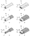
図1(a)~(f)は、本発明の一実施形態に係る電線の構成例を説明する模式図である。
FIGS. 1A to 1F are schematic views for explaining an example of the configuration of an electric wire according to an embodiment of the present invention.
図1(a)は、第1の導体としての低融点金属からなる金属素線の表面を第2の導体としての高融点金属で被覆して構成された導電材を備えた電線の態様を示す図である。
Fig.1 (a) shows the aspect of the electric wire provided with the electrically conductive material comprised by coat | covering the surface of the metal strand which consists of a low melting metal as a 1st conductor with the high melting metal as a 2nd conductor. FIG.
図1(a)に示されるように、電線10は、径方向の断面形状が円形として構成された低融点金属からなる金属素線1表面を高融点金属でメッキ処理することにより金属層2が形成された導電材3を備える。
As shown in FIG. 1A, the electric wire 10 has a metal layer 2 formed by plating a surface of a metal element wire 1 made of a low melting point metal having a circular cross-sectional shape in a radial direction with a high melting point metal. The formed conductive material 3 is provided.
本発明における低融点金属としては、融点が300℃以下、好ましくは260℃以下の金属材料とされ、例えば、錫、半田(錫-鉛合金)、錫-銅合金、錫-ビスマス合金、錫-銀合金といった錫を主成分とした合金等を用いることができる。そして、これらの金属材料に対して圧延、伸線、アニール処理等を施すことにより、所望の断面積を有する金属素線1を得ることができる。
The low melting point metal in the present invention is a metal material having a melting point of 300 ° C. or less, preferably 260 ° C. or less. For example, tin, solder (tin-lead alloy), tin-copper alloy, tin-bismuth alloy, tin— An alloy mainly composed of tin, such as a silver alloy, can be used. And the metal strand 1 which has a desired cross-sectional area can be obtained by performing rolling, wire drawing, annealing treatment, etc. with respect to these metal materials.
低融点金属からなる金属素線1の断面積としては、所定の電流値(過電流値)での溶断が可能となるように適宜設定することができる。また、金属素線1の単位長さ当たりの総体積は、金属層2の単位長さ当たりの総体積よりも多くなるように定められる。ここで、導電材3の単位長さ当たりの総体積に対する金属素線1の体積は50%以上となるように調整するのが好ましい。
The cross-sectional area of the metal element wire 1 made of a low melting point metal can be appropriately set so as to enable fusing at a predetermined current value (overcurrent value). Further, the total volume per unit length of the metal strand 1 is determined to be larger than the total volume per unit length of the metal layer 2. Here, it is preferable that the volume of the metal strand 1 with respect to the total volume per unit length of the conductive material 3 is adjusted to be 50% or more.
本発明における高融点金属としては、融点が900℃以上、好ましくは960℃以上の金属材料とされ、例えば、銀、銅、鉄、銀を主成分とする合金、銅を主成分とする合金、鉄を主成分とする合金、ブリキ、又はトタン等を用いることができる。そして、例えば、溶解メッキ、気相メッキ、電気メッキ、化学メッキ等のメッキ処理を金属素線1に対して施すことにより、これらの金属材料からなる金属層2を金属素線1表面上に形成することができる。なお、導電材3の単位長さ当たりの総体積に対する金属層2の体積は20%以下となるように調整するのが更に好ましく、電線としての所定の電気伝導性を示す上で適宜設定可能である。
The refractory metal in the present invention is a metal material having a melting point of 900 ° C. or higher, preferably 960 ° C. or higher. For example, silver, copper, iron, an alloy containing silver as a main component, an alloy containing copper as a main component, An alloy mainly composed of iron, tin, tin, or the like can be used. Then, for example, a metal layer 2 made of these metal materials is formed on the surface of the metal element wire 1 by performing plating treatment such as dissolution plating, vapor phase plating, electroplating, and chemical plating on the metal element wire 1. can do. The volume of the metal layer 2 is more preferably adjusted to 20% or less with respect to the total volume per unit length of the conductive material 3, and can be set as appropriate in order to exhibit predetermined electrical conductivity as an electric wire. is there.
図1(a)に示す電線10は、低融点金属かなる金属素線1の表面が高融点金属からなる金属層2で直接メッキ被膜されていることから、第1の導体としての低融点金属と第2の導体としての高融点金属との密着性が高められ、且つ、電線としての所定の電気伝導性を有しながらも機械的強度に優れたものとなっている。そして、電線10によれば、電気回路内に過電流が流れることにより発熱した場合においても、高融点金属自体の融点よりも低い温度(凡そ300℃~400℃)で導電材3自体が溶断することで電流通電を確実に遮断することができる。なお、図1(a)に示す例においては、金属素線1の径方向の断面形状が円形として構成された形態について説明したが、例えば、図1(b)に示すように、本発明に係る電線を金属素線1の断面形状が矩形状に形成されたリボン状の電線20として構成することも可能である。
An electric wire 10 shown in FIG. 1A has a low melting point metal as a first conductor because the surface of a metal wire 1 made of a low melting point metal is directly plated with a metal layer 2 made of a high melting point metal. And the high melting point metal as the second conductor are improved, and the mechanical strength is excellent while having the predetermined electrical conductivity as the electric wire. According to the electric wire 10, the conductive material 3 itself is melted at a temperature lower than the melting point of the refractory metal itself (approximately 300 ° C. to 400 ° C.) even when heat is generated due to overcurrent flowing in the electric circuit. Thus, current conduction can be reliably interrupted. In the example shown in FIG. 1 (a), the embodiment has been described in which the cross-sectional shape in the radial direction of the metal strand 1 is configured as a circle. For example, as shown in FIG. It is also possible to configure the electric wire as a ribbon-like electric wire 20 in which the cross-sectional shape of the metal strand 1 is formed in a rectangular shape.
図1(c)は、第1の導体としての低融点金属からなる金属素線の表面を第2の導体としての高融点金属で被覆して構成された導電材を絶縁材で覆った態様を示す図である。
FIG. 1C shows an embodiment in which a conductive material formed by coating the surface of a metal wire made of a low melting point metal as a first conductor with a high melting point metal as a second conductor is covered with an insulating material. FIG.
図1(c)に示されるように、電線30は、径方向の断面形状が円形として構成された低融点金属からなる金属素線1の表面を高融点金属でメッキ処理することにより金属層2が形成された導電材3と、当該導電材3を覆う絶縁材4とを備える。
As shown in FIG. 1 (c), the electric wire 30 has a metal layer 2 formed by plating the surface of a metal strand 1 made of a low melting point metal having a circular cross-sectional shape in the radial direction with a high melting point metal. And the insulating material 4 covering the conductive material 3.
図1(c)に示す電線30は、図1(a)を用いて説明した電線10の導電材3の外周面、すなわち、高融点金属からなる金属層2の外周面が絶縁材4によって覆われた形態となっている。そして、絶縁材4の発火点は、低融点金属からなる金属素線1の融点よりも高い温度とされる。これにより、電気回路内に過電流が流れることにより発熱した場合においても、絶縁材4が発火する前に導電材3自体が溶断することで電流通電が確実に遮断され、絶縁材4の発火に伴う火災事故の発生を未然に防ぐことができる。
An electric wire 30 shown in FIG. 1C has an insulating material 4 covering the outer peripheral surface of the conductive material 3 of the electric wire 10 described with reference to FIG. 1A, that is, the outer peripheral surface of the metal layer 2 made of a refractory metal. It is a broken form. The ignition point of the insulating material 4 is set to a temperature higher than the melting point of the metal strand 1 made of a low melting point metal. As a result, even when heat is generated due to an overcurrent flowing in the electric circuit, the conductive material 3 itself is blown before the insulating material 4 is ignited, so that current conduction is reliably interrupted, and the insulating material 4 is ignited. The accompanying fire accident can be prevented in advance.
絶縁材4の材質としては絶縁性有機高分子組成物、すなわち、絶縁性樹脂等の絶縁性有機高分子に、難燃剤、架橋剤、酸化防止剤等の各種添加物を配合したものを用いることができ、これを導電材3の外周面に対して押出又は塗工することで絶縁材4としての絶縁材層を形成することができる。絶縁性樹脂しては、例えば、ポリプロピレン、ポリ塩化ビニル、ポリ塩化ビニリデン、ポリテトラフルオロエチレン、ポリスチレン、スチレン-アクリロニトリル共重合体、スチレン-メタクリル酸メチル共重合体、ポリメタクリル酸メチル、酢酸セルロース、ポリアミド、フェノール樹脂、メラミン樹脂、シリコーン樹脂、不飽和ポリエステル等を挙げることができる。これらの絶縁性樹脂は単独で用いてもよく、複数組み合わせてもよい。上記に加え、絶縁材4の材質は、溶食による導電材3の形態変化(変形、切断等)、視認による溶断の有無の確認等の事情を鑑みて、低融点金属からなる金属素線1の融点よりも低い温度で熱変形を生じる材質であることが好ましい。すなわち、絶縁材4が熱変形することにより、外見から電線内部に異常が発生したことを把握することができる。なお、図1(c)に示す例においては、金属素線1の径方向の断面形状が円形として構成された形態について説明したが、例えば、図1(d)に示すように、本発明に係る電線を金属素線1の断面形状が矩形状に形成されたリボン状の電線40として構成することも可能である。
The insulating material 4 is made of an insulating organic polymer composition, that is, an insulating organic polymer such as an insulating resin mixed with various additives such as a flame retardant, a crosslinking agent, and an antioxidant. The insulating material layer as the insulating material 4 can be formed by extruding or coating this on the outer peripheral surface of the conductive material 3. Examples of the insulating resin include polypropylene, polyvinyl chloride, polyvinylidene chloride, polytetrafluoroethylene, polystyrene, styrene-acrylonitrile copolymer, styrene-methyl methacrylate copolymer, polymethyl methacrylate, cellulose acetate, Polyamide, phenol resin, melamine resin, silicone resin, unsaturated polyester, etc. can be mentioned. These insulating resins may be used alone or in combination. In addition to the above, the material of the insulating material 4 is a metal strand 1 made of a low-melting-point metal in view of changes in the shape of the conductive material 3 due to corrosion (deformation, cutting, etc.) and confirmation of the presence or absence of fusing by visual recognition. A material that causes thermal deformation at a temperature lower than its melting point is preferred. That is, when the insulating material 4 is thermally deformed, it can be understood from the appearance that an abnormality has occurred inside the electric wire. In addition, in the example shown in FIG.1 (c), although the cross-sectional shape of the radial direction of the metal strand 1 was demonstrated as a circular shape, for example, as shown in FIG. It is also possible to configure the electric wire as a ribbon-like electric wire 40 in which the cross-sectional shape of the metal strand 1 is formed in a rectangular shape.
図1(e)は、第1の導体としての低融点金属からなる金属素線と第2の導体としての高融点金属からなる金属素線とをそれぞれ数本撚り合わせて構成された導電材を絶縁材で覆った態様を示す図である。
FIG. 1 (e) shows a conductive material formed by twisting several metal strands made of a low melting point metal as a first conductor and several metal strands made of a high melting point metal as a second conductor. It is a figure which shows the aspect covered with the insulating material.
図1(e)に示されるように、電線50は、径方向の断面形状が円形として構成された低融点金属からなる金属素線11と、同じく径方向の断面形状が円形として構成された高融点金属からなる金属素線21とのそれぞれを数本撚り合わせて構成された導電材31と、当該導電材31を覆う絶縁材4とを備える。
As shown in FIG. 1 (e), the electric wire 50 includes a metal strand 11 made of a low-melting-point metal having a radial cross-sectional shape configured as a circle, and a high-diameter having a radial cross-sectional shape configured as a circle. A conductive material 31 formed by twisting several metal strands 21 made of a melting point metal and an insulating material 4 covering the conductive material 31 are provided.
低融点金属からなる金属素線11としては、図1(a)で示した金属素線1と同様に、融点が300℃以下、好ましくは260℃以下の金属材料とされ、例えば、錫、半田(錫-鉛合金)、錫-銅合金、錫-ビスマス合金、錫-銀合金といった錫を主成分とした合金等を用いることができる。そして、これらの金属材料に対して圧延、伸線、アニール処理等を施すことにより、所望の断面積を有する金属素線11を得ることができる。
The metal strand 11 made of a low melting point metal is a metal material having a melting point of 300 ° C. or lower, preferably 260 ° C. or lower, like the metal strand 1 shown in FIG. An alloy mainly composed of tin such as (tin-lead alloy), tin-copper alloy, tin-bismuth alloy, tin-silver alloy, or the like can be used. And the metal strand 11 which has a desired cross-sectional area can be obtained by performing rolling, wire drawing, annealing treatment, etc. with respect to these metal materials.
低融点金属からなる金属素線11の断面積としては、金属素線数本を撚り合わせた場合に所定の電流値(過電流値)での溶断が可能となるように適宜設定することができる。また、金属素線11の単位長さ当たりの総体積は、金属素線21の単位長さ当たりの総体積よりも多くなるように定められる。ここで、導電材31の単位長さ当たりの総体積に対する金属素線11の体積は50%以上となるように調整するのが好ましい。
The cross-sectional area of the metal strand 11 made of a low-melting-point metal can be appropriately set so that fusing with a predetermined current value (overcurrent value) is possible when several metal strands are twisted together. . Further, the total volume per unit length of the metal strand 11 is determined to be larger than the total volume per unit length of the metal strand 21. Here, the volume of the metal wire 11 with respect to the total volume per unit length of the conductive material 31 is preferably adjusted to be 50% or more.
高融点金属からなる金属素線21としては、図1(a)で示した金属層2と同様に、融点が900℃以上、好ましくは960℃以上の金属材料とされ、例えば、銀、銅、鉄、銀を主成分とする合金、銅を主成分とする合金、鉄を主成分とする合金、ブリキ、又はトタン等を用いることができる。そしてこれらの金属材料に対して圧延、伸線、アニール処理等を施すことにより、所望の断面積を有する金属素線21を得ることができる。なお、導電材31の単位長さ当たりの総体積に対する金属素線21の体積は20%以下となるように調整するのが更に好ましく、電線としての所定の電気伝導性を示す上で適宜設定可能である。
The metal strand 21 made of a refractory metal is a metal material having a melting point of 900 ° C. or higher, preferably 960 ° C. or higher, like the metal layer 2 shown in FIG. 1A. For example, silver, copper, An alloy containing iron or silver as a main component, an alloy containing copper as a main component, an alloy containing iron as a main component, tinplate, or tin can be used. And metal strand 21 which has a desired cross-sectional area can be obtained by performing rolling, wire drawing, annealing treatment, etc. with respect to these metal materials. In addition, it is more preferable to adjust the volume of the metal wire 21 with respect to the total volume per unit length of the conductive material 31 to be 20% or less, and can be set as appropriate in order to show predetermined electrical conductivity as an electric wire. It is.
図1(e)に示す電線50の例においては、撚り合わせる金属素線11及び金属素線21のそれぞれの本数を調整することにより、上記した導電材31の単位長さ当たりの総体積に対する好適な体積比とすることができる。このようにして構成された導電材31の外周に、図1(c)で示した電線30と同様な絶縁性有機高分子組成物からなる絶縁材4を被覆することにより、電線50を得ることができる。
In the example of the electric wire 50 shown in FIG.1 (e), it is suitable with respect to the total volume per unit length of the above-mentioned electrically conductive material 31 by adjusting the number of each of the metal strand 11 and the metal strand 21 twisted together. The volume ratio can be made small. The electric wire 50 is obtained by covering the outer periphery of the conductive material 31 thus configured with the insulating material 4 made of the same insulating organic polymer composition as the electric wire 30 shown in FIG. Can do.
ところで、金属素線11及び金属素線21を数本撚り合わせて構成した導電材31の素線間には隙間があるため、見かけ上の体積が大きい状態となっている。このような状態において、金属素線11が融解すると、融解状態の低融点金属の移動範囲が広くなる。その結果、低融点金属は広範囲において高融点金属上に拡散することが可能となるため、溶食現象をより促進させることができる。
Incidentally, since there is a gap between the strands of the conductive material 31 formed by twisting several metal strands 11 and 21, the apparent volume is large. In such a state, when the metal strand 11 is melted, the movement range of the low melting point metal in the melted state is widened. As a result, the low melting point metal can diffuse over the high melting point metal in a wide range, so that the corrosion phenomenon can be further promoted.
なお、図1(e)に示す電線50の例においては、金属素線11及び金属素線21を撚り合わせる形態として、互いの金属素線を隣接させた状態でストレート状に束ねた形態として説明したが、これに限定されず、例えば、金属素線11に対して金属素線21を連続的に横(斜め)巻きすることで絡み付ける、金属素線21に対して金属素線11を連続的に横(斜め)巻きすることで絡み付ける、互いの金属素線を編組するといった形態も可能である。
In addition, in the example of the electric wire 50 shown in FIG.1 (e), as a form which twists the metal strand 11 and the metal strand 21, it demonstrates as a form bundled in the straight form in the state which mutually adjoined the metal strand. However, the present invention is not limited to this. For example, the metal strands 11 are continuously entangled with the metal strands 21 that are entangled by winding the metal strands 21 continuously (obliquely) around the metal strands 11. For example, it is possible to entangle by winding horizontally (obliquely) or braiding the metal wires of each other.
図1(f)は、第1の導体としての低融点金属からなる層状体と第2の導体としての高融点金属からなる層状体とを積層して構成された導電材を絶縁材で覆った態様を示す図である。
In FIG. 1 (f), a conductive material formed by laminating a layered body made of a low melting point metal as a first conductor and a layered body made of a high melting point metal as a second conductor is covered with an insulating material. It is a figure which shows an aspect.
図1(f)に示されるように、電線60は、断面形状が矩形状として構成された低融点金属からなる層状体12と、同じく断面形状が矩形状として構成された高融点金属からなる2つの層状体22とにより形成された導電材32と、当該導電材32を覆う絶縁材4とを備える。
As shown in FIG. 1 (f), the electric wire 60 includes a layered body 12 made of a low-melting-point metal having a rectangular cross-sectional shape and a high-melting-point metal 2 having a rectangular cross-sectional shape. A conductive material 32 formed by two layered bodies 22 and an insulating material 4 covering the conductive material 32 are provided.
低融点金属からなる層状体12としては、図1(a)~図1(e)で示した金属素線1と同様な金属材料を用いることができ、これらの金属材料に対して圧延処理等を施すことにより、所望の断面積を有する層状体12を得ることができる。
As the layered body 12 made of a low melting point metal, a metal material similar to the metal strand 1 shown in FIGS. 1 (a) to 1 (e) can be used. By applying the above, a layered body 12 having a desired cross-sectional area can be obtained.
低融点金属からなる層状体12の断面積としては、所定の電流値(過電流値)での溶断が可能となるように適宜設定することができる。また、層状体12の単位長さ当たりの総体積は、層状体22の単位長さ当たりの総体積よりも多くなるように定められる。ここで、導電材32の単位長さ当たりの総体積に対する層状体12の体積は50%以上となるように調整するのが好ましい。
The cross-sectional area of the layered body 12 made of a low-melting-point metal can be appropriately set so that fusing at a predetermined current value (overcurrent value) is possible. Further, the total volume per unit length of the layered body 12 is determined to be larger than the total volume per unit length of the layered body 22. Here, the volume of the layered body 12 with respect to the total volume per unit length of the conductive material 32 is preferably adjusted to be 50% or more.
高融点金属からなる層状体22としては、図1(a)~図1(e)で示した金属層2と同様な金属材料を用いることができ、これらの金属材料に対して圧延処理等を施すことにより、所望の断面積を有する層状体22を得ることができる。なお、導電材32の単位長さ当たりの総体積に対する層状体22の体積は20%以下となるように調整するのが更に好ましく、電線としての所定の電気伝導性を示す上で適宜設定可能である。
As the layered body 22 made of a refractory metal, a metal material similar to that of the metal layer 2 shown in FIGS. 1A to 1E can be used. By applying, the layered body 22 having a desired cross-sectional area can be obtained. The volume of the layered body 22 with respect to the total volume per unit length of the conductive material 32 is more preferably adjusted to be 20% or less, and can be set as appropriate in order to exhibit predetermined electrical conductivity as an electric wire. is there.
図1(f)に示す電線60の例においては、積層する層状体12及び層状体22のそれぞれの積層数を調整することにより、上記した導電材32の単位長さ当たりの総体積に対する好適な体積比とすることができる。層状体12に対する層状体22の積層方法としては、例えば、圧着接続法、ろう付けによる溶融接続法、所謂半田付け等を用いることができる。例えば、低融点金属からなる層状体12が半田から構成されている場合、高融点金属からなる層状体22との接続に同じ金属材料である半田を用いたろう付けが可能であるため、層状体の積層に係るコストを抑えることができると共に、用いられる金属材料が少ないことから製品純度を高めることができる。このようにして構成された導電材32の外周に、図1(c)で示した電線30と同様な絶縁性有機高分子組成物からなる絶縁材4を被覆することにより、電線60を得ることができる。
In the example of the electric wire 60 shown in FIG.1 (f), it is suitable with respect to the total volume per unit length of the above-mentioned electrically-conductive material 32 by adjusting each lamination | stacking number of the layered body 12 and the layered body 22 to laminate | stack. It can be a volume ratio. As a method for laminating the layered body 22 to the layered body 12, for example, a crimp connection method, a fusion connection method by brazing, so-called soldering, or the like can be used. For example, when the layered body 12 made of a low-melting-point metal is made of solder, brazing using solder that is the same metal material can be used for connection to the layered body 22 made of a high-melting-point metal. The cost for stacking can be reduced, and the product purity can be increased because fewer metal materials are used. By covering the outer periphery of the conductive material 32 thus configured with the insulating material 4 made of the same insulating organic polymer composition as the electric wire 30 shown in FIG. 1C, the electric wire 60 is obtained. Can do.
図1(f)に示す電線60は、低融点金属かなる層状体12の表面が高融点金属からなる2つの層状体22で接続(積層)されていることから、第1の導体としての低融点金属と第2の導体としての高融点金属との密着性が高められ、且つ、電線としての所定の電気伝導性を有しながらも機械的強度に優れたものとなっている。そして、電線10によれば、電気回路内に過電流が流れることにより発熱した場合においても、高融点金属自体の融点よりも低い温度で導電材32自体が溶断することで電流通電を確実に遮断することができる。
Since the surface of the layered body 12 made of a low-melting-point metal is connected (laminated) with two layered bodies 22 made of a high-melting-point metal, the electric wire 60 shown in FIG. Adhesiveness between the melting point metal and the high melting point metal as the second conductor is enhanced, and it has excellent mechanical strength while having predetermined electrical conductivity as an electric wire. And according to the electric wire 10, even when heat is generated due to an overcurrent flowing in the electric circuit, the conductive material 32 itself melts at a temperature lower than the melting point of the refractory metal itself, thereby reliably interrupting current conduction. can do.
なお、図1(a)~図1(f)に示す例、特に、図1(a)~図1(d)、図1(f)に示す例においては、低融点金属からなる第1の導体の周囲を高融点金属からなる第2の導体で覆う形態について説明したが、本発明はこれに限定されるものではなく、高融点金属からなる第2の導体の周囲を低融点金属からなる第1の導体で覆う形態としてもかまわない。例えば、図1(a)に示す電線10の例で言えば、高融点金属からなる第2の導体としての金属素線1を低融点金属からなる第1の導体としての金属層2でメッキ被覆する形態とすることができる。この場合、金属素線1をより細線化するとともに、金属層2の層厚をより厚くすることで、上記した導電材の単位長さ当たりの総体積に対する好適な体積比とすることができる。
In the examples shown in FIGS. 1 (a) to 1 (f), particularly in the examples shown in FIGS. 1 (a) to 1 (d) and FIG. 1 (f), the first made of a low melting point metal is used. Although the embodiment in which the periphery of the conductor is covered with the second conductor made of the refractory metal has been described, the present invention is not limited to this, and the periphery of the second conductor made of the refractory metal is made of the low melting point metal. It does not matter as a form of covering with the first conductor. For example, in the example of the electric wire 10 shown in FIG. 1A, the metal element wire 1 as the second conductor made of a high melting point metal is plated with the metal layer 2 as the first conductor made of a low melting point metal. It can be set as a form to do. In this case, it is possible to obtain a suitable volume ratio with respect to the total volume per unit length of the conductive material by making the metal strand 1 thinner and increasing the thickness of the metal layer 2.
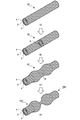
図2(a)~図2(f)は、本発明の他実施形態に係る電線の構成例を説明する模式図である。なお、本実施形態に係る低融点金属、高融点金属、絶縁性有機高分子組成物等は、図1(a)~図1(f)で示した電線10~60と同じ材料を用いることができる。
FIGS. 2 (a) to 2 (f) are schematic diagrams for explaining a configuration example of an electric wire according to another embodiment of the present invention. Note that the low melting point metal, the high melting point metal, the insulating organic polymer composition, and the like according to the present embodiment are made of the same material as that of the electric wires 10 to 60 shown in FIGS. 1 (a) to 1 (f). it can.
図2(a)に示す電線70は、径方向の断面形状が円形として構成された低融点金属からなる金属素線1'表面を高融点金属でメッキ処理することにより金属層2'が形成された導電材3'と、導電材3'内部、すなわち、金属素線1'内の中心部分に細線状のフラックス5とを備える。
An electric wire 70 shown in FIG. 2 (a) has a metal layer 2 'formed by plating the surface of a metal strand 1' made of a low melting point metal having a circular shape in cross section in the radial direction with a high melting point metal. The conductive material 3 ′ and the thin wire-like flux 5 are provided in the conductive material 3 ′, that is, in the central portion of the metal strand 1 ′.
本発明におけるフラックス5とは、金属表面の酸化膜を化学的に除去する松脂等の物質を指し、融解状態の低融点金属の拡散を促すことができるものである。したがって、導電材3'内部にフラックス5を保持する電線70によれば、電気回路内に過電流が流れることにより発熱した場合においても、低融点金属が効率良く高融点金属上を拡散することにより溶食がより促進され、高融点金属自体の融点よりも低い温度で導電材3'自体が溶断することで電流通電を確実に遮断することができる。また、図1(a)に示す電線10と同様に、低融点金属かなる金属素線1'の表面が高融点金属からなる金属層2'で直接メッキ被膜されていることから、第1の導体としての低融点金属と第2の導体としての高融点金属との密着性が高められ、且つ、電線としての所定の電気伝導性を有しながらも機械的強度に優れたものとなっている。なお、図2(a)に示す例においては、金属素線1'の径方向の断面形状が円形として構成された形態について説明したが、図2(b)に示すように、本発明に係る電線を金属素線1'内にフラックス5を備え、断面形状が矩形状に形成されたリボン状の電線80として構成することも可能である。
The flux 5 in the present invention refers to a substance such as pine resin that chemically removes the oxide film on the metal surface, and can promote the diffusion of the low melting point metal in the molten state. Therefore, according to the electric wire 70 holding the flux 5 inside the conductive material 3 ′, even when heat is generated due to overcurrent flowing in the electric circuit, the low melting point metal efficiently diffuses on the high melting point metal. Since the corrosion is further promoted and the conductive material 3 ′ is melted at a temperature lower than the melting point of the refractory metal itself, current conduction can be reliably interrupted. Further, similarly to the electric wire 10 shown in FIG. 1A, the surface of the metal element wire 1 ′ made of a low melting point metal is directly plated with a metal layer 2 ′ made of a high melting point metal. The adhesion between the low melting point metal as the conductor and the high melting point metal as the second conductor is enhanced, and the mechanical strength is excellent while having the predetermined electrical conductivity as the electric wire. . In the example shown in FIG. 2 (a), the embodiment has been described in which the radial cross-sectional shape of the metal strand 1 ′ is configured as a circle. However, as shown in FIG. It is also possible to configure the electric wire as a ribbon-shaped electric wire 80 having a flux 5 in the metal strand 1 'and having a rectangular cross-sectional shape.
図2(c)に示す電線90は、径方向の断面形状が円形として構成された低融点金属からなる金属素線1'表面を高融点金属でメッキ処理することにより金属層2'が形成された導電材3'と、当該導電材3'を覆う絶縁材4'と、導電材3'内部、すなわち、金属素線1'内の中心部分に細線状のフラックス5とを備える。
An electric wire 90 shown in FIG. 2 (c) has a metal layer 2 'formed by plating the surface of a metal strand 1' made of a low melting point metal having a circular shape in cross section in the radial direction with a high melting point metal. The conductive material 3 ′, the insulating material 4 ′ covering the conductive material 3 ′, and the thin wire-like flux 5 are provided in the conductive material 3 ′, that is, in the central portion of the metal strand 1 ′.
導電材3'内部にフラックス5を保持する電線90によれば、電気回路内に過電流が流れることにより発熱した場合においても、低融点金属が効率良く高融点金属上を拡散することにより溶食がより促進され、高融点金属自体の融点よりも低い温度で導電材3'自体が溶断することで電流通電を確実に遮断することができる。また、電線90は、図1(c)で示した電線30と同様に、導電材3'の外周面、すなわち、高融点金属からなる金属層2'の外周面が絶縁材4'によって覆われた形態となっており、絶縁材4'の発火点は、低融点金属からなる金属素線1'の融点よりも高い温度とされるため、電気回路内に過電流が流れることにより発熱した場合においても、絶縁材4'が発火する前に導電材3'自体が溶断することで電流通電が確実に遮断され、絶縁材4'の発火に伴う火災事故の発生を未然に防ぐことができる。なお、図2(c)に示す例においては、金属素線1'の径方向の断面形状が円形として構成された形態について説明したが、図2(d)に示すように、本発明に係る電線を金属素線1'内にフラックス5を備え、断面形状が矩形状に形成されたリボン状の電線100として構成することも可能である。
According to the electric wire 90 that holds the flux 5 inside the conductive material 3 ′, even when heat is generated due to an overcurrent flowing in the electric circuit, the low melting point metal efficiently diffuses on the high melting point metal to cause corrosion. Is further promoted, and the conductive material 3 ′ itself is melted at a temperature lower than the melting point of the refractory metal itself, so that current conduction can be reliably interrupted. Further, in the electric wire 90, the outer peripheral surface of the conductive material 3 ′, that is, the outer peripheral surface of the metal layer 2 ′ made of a refractory metal is covered with the insulating material 4 ′ in the same manner as the electric wire 30 shown in FIG. The ignition point of the insulating material 4 ′ is higher than the melting point of the metal strand 1 ′ made of a low melting point metal, so that heat is generated by overcurrent flowing in the electric circuit. In this case, the conductive material 3 ′ itself is blown before the insulating material 4 ′ is ignited, so that current conduction is reliably interrupted, and the occurrence of a fire accident due to the ignition of the insulating material 4 ′ can be prevented. In the example shown in FIG. 2C, the embodiment has been described in which the radial cross-sectional shape of the metal strand 1 ′ is configured as a circle. However, as shown in FIG. It is also possible to configure the electric wire as a ribbon-shaped electric wire 100 having a flux 5 in the metal strand 1 'and having a rectangular cross-sectional shape.
図2(e)に示す電線110は、径方向の断面形状が円形として構成された低融点金属からなる金属素線11'と、同じく径方向の断面形状が円形として構成された高融点金属からなる金属素線21'とのそれぞれを数本撚り合わせて構成された導電材31'と、当該導電材31'を覆う絶縁材4'と、導電材31'内部、すなわち、金属素線11'と金属素線21'との撚り合わせ中心部分に細線状のフラックス5とを備える。
An electric wire 110 shown in FIG. 2 (e) is made of a metal strand 11 ′ made of a low-melting point metal having a circular cross-sectional shape in the radial direction and a high-melting point metal having a circular cross-sectional shape in the same radial direction. A conductive material 31 ′ formed by twisting several of each of the metal wires 21 ′, an insulating material 4 ′ covering the conductive material 31 ′, and the inside of the conductive material 31 ′, that is, the metal wire 11 ′. And a thin wire-like flux 5 are provided at the center portion of the twisted wire and the metal strand 21 '.
導電材31'内部にフラックス5を保持する電線110によれば、電気回路内に過電流が流れることにより発熱した場合においても、図1(e)で示した電線50の構造的効果に加え、低融点金属が効率良く高融点金属上を拡散することにより溶食がより促進され、高融点金属自体の融点よりも低い温度で導電材31'自体が溶断することで電流通電を確実に遮断することができる。
According to the electric wire 110 holding the flux 5 inside the conductive material 31 ′, in addition to the structural effect of the electric wire 50 shown in FIG. 1 (e), even when heat is generated due to overcurrent flowing in the electric circuit, Efficient diffusion of the low melting point metal on the high melting point metal promotes corrosion, and the conductive material 31 'itself blows at a temperature lower than the melting point of the high melting point metal itself, thereby reliably interrupting current conduction. be able to.
図2(f)に示す電線120は、断面形状が矩形状として構成された低融点金属からなる層状体12'と、同じく断面形状が矩形状として構成された高融点金属からなる2つの層状体22'とにより形成された導電材32'と、当該導電材32'を覆う絶縁材4'と、導電材32'内部、すなわち、層状体12'内の中心部分に層状のフラックス5とを備える。
An electric wire 120 shown in FIG. 2 (f) includes a layered body 12 ′ made of a low-melting point metal having a rectangular cross-sectional shape and two layered bodies made of a high-melting point metal having the same cross-sectional shape. 22 ′, an insulating material 4 ′ covering the conductive material 32 ′, and a layered flux 5 in the conductive material 32 ′, that is, in the central portion of the layered body 12 ′. .
導電材32'内部にフラックス5を保持する電線120によれば、電気回路内に過電流が流れることにより発熱した場合においても、低融点金属が効率良く高融点金属上を拡散することにより溶食がより促進され、高融点金属自体の融点よりも低い温度で導電材32'自体が溶断することで電流通電を確実に遮断することができる。また、図1(f)に示す電線60と同様に、低融点金属かなる層状体12'の表面が高融点金属からなる2つの層状体22'で接続(積層)されていることから、第1の導体としての低融点金属と第2の導体としての高融点金属との密着性が高められ、且つ、電線としての所定の電気伝導性を有しながらも機械的強度に優れたものとなっている。
According to the electric wire 120 that holds the flux 5 inside the conductive material 32 ', even when heat is generated due to an overcurrent flowing in the electric circuit, the low melting point metal efficiently diffuses on the high melting point metal to cause corrosion. Is further promoted, and the conductive material 32 ′ itself is melted at a temperature lower than the melting point of the refractory metal itself, so that current conduction can be reliably interrupted. Similarly to the electric wire 60 shown in FIG. 1 (f), the surface of the layered body 12 ′ made of a low melting point metal is connected (laminated) with two layered bodies 22 ′ made of a high melting point metal. The adhesion between the low-melting point metal as the first conductor and the high-melting point metal as the second conductor is enhanced, and the mechanical strength is excellent while having predetermined electrical conductivity as the electric wire. ing.
なお、図2(a)~図2(f)に示す例においては、フラックスを低融点金属からなる金属素線、層状体等の中心部分に設けた形態について説明したが、これに限定されず、例えば、図2(a)に示す電線70の例で言えば、金属素線1'と金属層2'との間にフラックスを設けたり、金属層2'の外周をフラックスで被覆する形態としてもかまわない。
In the examples shown in FIGS. 2 (a) to 2 (f), the embodiment has been described in which the flux is provided in the central portion of the metal strand made of a low melting point metal, the layered body, etc., but is not limited thereto. For example, in the example of the electric wire 70 shown in FIG. 2A, a form in which a flux is provided between the metal strand 1 ′ and the metal layer 2 ′, or the outer periphery of the metal layer 2 ′ is covered with the flux. It doesn't matter.
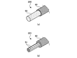
図3は、上記実施形態に係る電線の溶断経緯を説明する状態遷移図である。ここでの説明においては、図1(c)で説明した電線30を一例にして説明する。
FIG. 3 is a state transition diagram for explaining the fusing process of the electric wire according to the embodiment. In the description here, the electric wire 30 described in FIG. 1C will be described as an example.
まず、図3(a)において、電線30の両端に接続された図示せぬ電気回路に過電流が流れることにより発熱し、発熱温度が低融点金属からなる金属素線1の融点を超えると、図3(b)に示すように、金属素線1は融解し始め、元の電線形状を維持できなくなる。
First, in FIG. 3A, when an overcurrent flows through an electric circuit (not shown) connected to both ends of the electric wire 30, heat is generated, and when the heat generation temperature exceeds the melting point of the metal element wire 1 made of a low melting point metal, As shown in FIG.3 (b), the metal strand 1 begins to melt | dissolve and it becomes impossible to maintain the original electric wire shape.
そして、融解状態の低融点金属Xが、高融点金属からなる金属層2上を拡散することにより溶食作用が進行する。溶食作用に伴い高融点金属からなる金属層2も融解し始める。
Then, the low melting point metal X in the molten state diffuses on the metal layer 2 made of the high melting point metal, and the erosion action proceeds. Along with the erosion action, the metal layer 2 made of a refractory metal starts to melt.
図3(c)に示すように、溶食作用の進行に伴い絶縁材4の形態も熱変形し始め、溶断点P近傍の肉厚が薄くなることで、電線30'は元の断面径よりも縮径した状態となる。
As shown in FIG. 3 (c), the form of the insulating material 4 starts to thermally deform with the progress of the erosion action, and the thickness in the vicinity of the fusing point P becomes thin, so that the electric wire 30 'is smaller than the original cross-sectional diameter. Is also reduced in diameter.
最終的に電線30'は溶断点Pにおいて溶断し、溶断点P側の絶縁材4端部が塊状態となった電線30a',30b'を覆う様に変形する(図3(d))。
Finally, the electric wire 30 ′ is melted at the fusing point P, and the end of the insulating material 4 on the fusing point P side is deformed so as to cover the electric wires 30a ′ and 30b ′ in a lump state (FIG. 3D).
このように、本実施形態に係る電線によれば、電気回路内に過電流が流れることにより発熱した場合においても、高融点金属自体の融点よりも低い温度で導電材自体が溶断することで電流通電を確実に遮断することができる。そして、溶断点を介して分離した電線端は再結合することがないため、断線後に誤って通電されることがない。また、本電線が設置された周囲が低融点金属の融解温度以上に熱せられた場合も、同様に高融点金属自体の融点よりも低い温度で導電材自体が溶断することで電流通電を確実に遮断することができる。
As described above, according to the electric wire according to the present embodiment, even when heat is generated due to overcurrent flowing in the electric circuit, the conductive material itself melts at a temperature lower than the melting point of the refractory metal itself, so that the current flows. Energization can be reliably interrupted. And since the electric wire end isolate | separated via the fusing point does not recombine, it does not accidentally energize after disconnection. In addition, even when the surrounding area where the electric wire is installed is heated above the melting temperature of the low melting point metal, the conductive material itself is blown at a temperature lower than the melting point of the high melting point metal itself to ensure current conduction. Can be blocked.
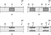
図4は、本発明の実施形態に係る電線の変形例を説明する模式図であり、電線の長尺方向に対する断面図として表した図である。図1及び図2で示した電線10~120は、低融点金属を有する部位が電線全長に亘って構成された例である。図4で説明する変形例では、低融点金属を有する部位が電線全長に対して部分的に設けられた構成について説明する。
FIG. 4 is a schematic diagram for explaining a modification of the electric wire according to the embodiment of the present invention, and is a view represented as a cross-sectional view with respect to the longitudinal direction of the electric wire. The electric wires 10 to 120 shown in FIGS. 1 and 2 are examples in which a portion having a low melting point metal is formed over the entire length of the electric wire. In the modification described in FIG. 4, a configuration in which a portion having a low melting point metal is partially provided with respect to the entire length of the electric wire will be described.
図4(a)に示す電線130は、電線全長に亘って構成された高融点金属からなる金属素線23の軸心近傍に低融点金属からなる導体部13が部分的に設けられた例であり、図4(c)に示す電線140は、電線全長に亘って構成された高融点金属からなる金属素線23'の径方向外側に低融点金属からなる導体部13'が部分的に設けられた例である。本変形例においても、低融点金属からなる第1の導体(導体部13,13')と高融点金属からなる第2の導体(金属素線23,23')とは互いに隣接して導電材を構成していることから、電気回路内に過電流が流れることにより発熱した場合においても、高融点金属自体の融点よりも低い温度で導電材自体が溶断することで電流通電を確実に遮断することができる。また、本変形例によれば、低融点金属からなる導体部13,13'は、高融点金属からなる金属素線23,23'に対して部分的に設けられていることから、溶断した箇所を電線外見から判別し易いという効果も得られる。なお、導体部13,13'は、金属素線23,23'に対して複数個所に亘って設けてもよく、その設置数に制限はない(図4(b),(d))。
An electric wire 130 shown in FIG. 4A is an example in which a conductor portion 13 made of a low melting point metal is partially provided in the vicinity of the axis of a metal strand 23 made of a high melting point metal that is formed over the entire length of the wire. The electric wire 140 shown in FIG. 4 (c) is partially provided with a conductor portion 13 ′ made of a low melting point metal on the outer side in the radial direction of the metal strand 23 ′ made of a high melting point metal formed over the entire length of the wire. This is an example. Also in this modification, the first conductor ( conductor portions 13, 13 ′) made of a low melting point metal and the second conductor ( metal strands 23, 23 ′) made of a high melting point metal are adjacent to each other and are electrically conductive. Therefore, even when heat is generated due to the overcurrent flowing in the electric circuit, the conductive material itself is blown at a temperature lower than the melting point of the refractory metal itself, thereby reliably interrupting current conduction. be able to. Moreover, according to this modification, since the conductor parts 13 and 13 ′ made of the low melting point metal are partially provided with respect to the metal strands 23 and 23 ′ made of the high melting point metal, the melted portion Is also easily obtained from the appearance of the electric wire. The conductor portions 13 and 13 ′ may be provided at a plurality of locations with respect to the metal wires 23 and 23 ′, and the number of the conductor portions 13 and 13 ′ is not limited (FIGS. 4B and 4D).
図1(c),(d),(f)、図2(c),(d),(f)では、導電材1本に対し絶縁材が覆われているが、所望の電線の許容電流に応じ複数本の導電材を束ねたり撚り合わさった状態で絶縁材を覆う構造としてもよい。
In FIGS. 1 (c), (d), (f) and FIGS. 2 (c), (d), (f), an insulating material is covered with respect to one conductive material, but the allowable current of a desired wire Accordingly, a structure may be adopted in which the insulating material is covered in a state where a plurality of conductive materials are bundled or twisted together.
以上のように、本発明によれば、高融点金属を用いることにより電気伝導性に優れ、電気回路内に過電流が流れることにより発熱した場合においても、当該高融点金属の融点よりも低い温度で導電材自体が溶断することで電流通電を遮断することが可能な電線を提供することができる。
As described above, according to the present invention, the use of a refractory metal is excellent in electrical conductivity, and even when heat is generated due to overcurrent flowing in an electric circuit, the temperature is lower than the melting point of the refractory metal. Thus, it is possible to provide an electric wire capable of interrupting current conduction when the conductive material itself is melted.