WO2016043163A1 - Microorganism culture method and culture device - Google Patents
Microorganism culture method and culture device Download PDFInfo
- Publication number
- WO2016043163A1 WO2016043163A1 PCT/JP2015/076043 JP2015076043W WO2016043163A1 WO 2016043163 A1 WO2016043163 A1 WO 2016043163A1 JP 2015076043 W JP2015076043 W JP 2015076043W WO 2016043163 A1 WO2016043163 A1 WO 2016043163A1
- Authority
- WO
- WIPO (PCT)
- Prior art keywords
- culture
- culture solution
- gas
- tank
- solution
- Prior art date
Links
Images


Classifications
-
- C—CHEMISTRY; METALLURGY
- C12—BIOCHEMISTRY; BEER; SPIRITS; WINE; VINEGAR; MICROBIOLOGY; ENZYMOLOGY; MUTATION OR GENETIC ENGINEERING
- C12M—APPARATUS FOR ENZYMOLOGY OR MICROBIOLOGY; APPARATUS FOR CULTURING MICROORGANISMS FOR PRODUCING BIOMASS, FOR GROWING CELLS OR FOR OBTAINING FERMENTATION OR METABOLIC PRODUCTS, i.e. BIOREACTORS OR FERMENTERS
- C12M41/00—Means for regulation, monitoring, measurement or control, e.g. flow regulation
- C12M41/30—Means for regulation, monitoring, measurement or control, e.g. flow regulation of concentration
- C12M41/36—Means for regulation, monitoring, measurement or control, e.g. flow regulation of concentration of biomass, e.g. colony counters or by turbidity measurements
-
- C—CHEMISTRY; METALLURGY
- C12—BIOCHEMISTRY; BEER; SPIRITS; WINE; VINEGAR; MICROBIOLOGY; ENZYMOLOGY; MUTATION OR GENETIC ENGINEERING
- C12M—APPARATUS FOR ENZYMOLOGY OR MICROBIOLOGY; APPARATUS FOR CULTURING MICROORGANISMS FOR PRODUCING BIOMASS, FOR GROWING CELLS OR FOR OBTAINING FERMENTATION OR METABOLIC PRODUCTS, i.e. BIOREACTORS OR FERMENTERS
- C12M33/00—Means for introduction, transport, positioning, extraction, harvesting, peeling or sampling of biological material in or from the apparatus
- C12M33/14—Means for introduction, transport, positioning, extraction, harvesting, peeling or sampling of biological material in or from the apparatus with filters, sieves or membranes
-
- C—CHEMISTRY; METALLURGY
- C12—BIOCHEMISTRY; BEER; SPIRITS; WINE; VINEGAR; MICROBIOLOGY; ENZYMOLOGY; MUTATION OR GENETIC ENGINEERING
- C12M—APPARATUS FOR ENZYMOLOGY OR MICROBIOLOGY; APPARATUS FOR CULTURING MICROORGANISMS FOR PRODUCING BIOMASS, FOR GROWING CELLS OR FOR OBTAINING FERMENTATION OR METABOLIC PRODUCTS, i.e. BIOREACTORS OR FERMENTERS
- C12M1/00—Apparatus for enzymology or microbiology
- C12M1/04—Apparatus for enzymology or microbiology with gas introduction means
- C12M1/06—Apparatus for enzymology or microbiology with gas introduction means with agitator, e.g. impeller
-
- C—CHEMISTRY; METALLURGY
- C12—BIOCHEMISTRY; BEER; SPIRITS; WINE; VINEGAR; MICROBIOLOGY; ENZYMOLOGY; MUTATION OR GENETIC ENGINEERING
- C12M—APPARATUS FOR ENZYMOLOGY OR MICROBIOLOGY; APPARATUS FOR CULTURING MICROORGANISMS FOR PRODUCING BIOMASS, FOR GROWING CELLS OR FOR OBTAINING FERMENTATION OR METABOLIC PRODUCTS, i.e. BIOREACTORS OR FERMENTERS
- C12M23/00—Constructional details, e.g. recesses, hinges
- C12M23/02—Form or structure of the vessel
-
- C—CHEMISTRY; METALLURGY
- C12—BIOCHEMISTRY; BEER; SPIRITS; WINE; VINEGAR; MICROBIOLOGY; ENZYMOLOGY; MUTATION OR GENETIC ENGINEERING
- C12M—APPARATUS FOR ENZYMOLOGY OR MICROBIOLOGY; APPARATUS FOR CULTURING MICROORGANISMS FOR PRODUCING BIOMASS, FOR GROWING CELLS OR FOR OBTAINING FERMENTATION OR METABOLIC PRODUCTS, i.e. BIOREACTORS OR FERMENTERS
- C12M27/00—Means for mixing, agitating or circulating fluids in the vessel
-
- C—CHEMISTRY; METALLURGY
- C12—BIOCHEMISTRY; BEER; SPIRITS; WINE; VINEGAR; MICROBIOLOGY; ENZYMOLOGY; MUTATION OR GENETIC ENGINEERING
- C12M—APPARATUS FOR ENZYMOLOGY OR MICROBIOLOGY; APPARATUS FOR CULTURING MICROORGANISMS FOR PRODUCING BIOMASS, FOR GROWING CELLS OR FOR OBTAINING FERMENTATION OR METABOLIC PRODUCTS, i.e. BIOREACTORS OR FERMENTERS
- C12M29/00—Means for introduction, extraction or recirculation of materials, e.g. pumps
- C12M29/04—Filters; Permeable or porous membranes or plates, e.g. dialysis
-
- C—CHEMISTRY; METALLURGY
- C12—BIOCHEMISTRY; BEER; SPIRITS; WINE; VINEGAR; MICROBIOLOGY; ENZYMOLOGY; MUTATION OR GENETIC ENGINEERING
- C12M—APPARATUS FOR ENZYMOLOGY OR MICROBIOLOGY; APPARATUS FOR CULTURING MICROORGANISMS FOR PRODUCING BIOMASS, FOR GROWING CELLS OR FOR OBTAINING FERMENTATION OR METABOLIC PRODUCTS, i.e. BIOREACTORS OR FERMENTERS
- C12M41/00—Means for regulation, monitoring, measurement or control, e.g. flow regulation
- C12M41/12—Means for regulation, monitoring, measurement or control, e.g. flow regulation of temperature
- C12M41/14—Incubators; Climatic chambers
-
- C—CHEMISTRY; METALLURGY
- C12—BIOCHEMISTRY; BEER; SPIRITS; WINE; VINEGAR; MICROBIOLOGY; ENZYMOLOGY; MUTATION OR GENETIC ENGINEERING
- C12M—APPARATUS FOR ENZYMOLOGY OR MICROBIOLOGY; APPARATUS FOR CULTURING MICROORGANISMS FOR PRODUCING BIOMASS, FOR GROWING CELLS OR FOR OBTAINING FERMENTATION OR METABOLIC PRODUCTS, i.e. BIOREACTORS OR FERMENTERS
- C12M41/00—Means for regulation, monitoring, measurement or control, e.g. flow regulation
- C12M41/12—Means for regulation, monitoring, measurement or control, e.g. flow regulation of temperature
- C12M41/18—Heat exchange systems, e.g. heat jackets or outer envelopes
-
- C—CHEMISTRY; METALLURGY
- C12—BIOCHEMISTRY; BEER; SPIRITS; WINE; VINEGAR; MICROBIOLOGY; ENZYMOLOGY; MUTATION OR GENETIC ENGINEERING
- C12N—MICROORGANISMS OR ENZYMES; COMPOSITIONS THEREOF; PROPAGATING, PRESERVING, OR MAINTAINING MICROORGANISMS; MUTATION OR GENETIC ENGINEERING; CULTURE MEDIA
- C12N1/00—Microorganisms, e.g. protozoa; Compositions thereof; Processes of propagating, maintaining or preserving microorganisms or compositions thereof; Processes of preparing or isolating a composition containing a microorganism; Culture media therefor
- C12N1/20—Bacteria; Culture media therefor
-
- C—CHEMISTRY; METALLURGY
- C12—BIOCHEMISTRY; BEER; SPIRITS; WINE; VINEGAR; MICROBIOLOGY; ENZYMOLOGY; MUTATION OR GENETIC ENGINEERING
- C12P—FERMENTATION OR ENZYME-USING PROCESSES TO SYNTHESISE A DESIRED CHEMICAL COMPOUND OR COMPOSITION OR TO SEPARATE OPTICAL ISOMERS FROM A RACEMIC MIXTURE
- C12P7/00—Preparation of oxygen-containing organic compounds
- C12P7/02—Preparation of oxygen-containing organic compounds containing a hydroxy group
- C12P7/04—Preparation of oxygen-containing organic compounds containing a hydroxy group acyclic
- C12P7/06—Ethanol, i.e. non-beverage
- C12P7/065—Ethanol, i.e. non-beverage with microorganisms other than yeasts
-
- Y—GENERAL TAGGING OF NEW TECHNOLOGICAL DEVELOPMENTS; GENERAL TAGGING OF CROSS-SECTIONAL TECHNOLOGIES SPANNING OVER SEVERAL SECTIONS OF THE IPC; TECHNICAL SUBJECTS COVERED BY FORMER USPC CROSS-REFERENCE ART COLLECTIONS [XRACs] AND DIGESTS
- Y02—TECHNOLOGIES OR APPLICATIONS FOR MITIGATION OR ADAPTATION AGAINST CLIMATE CHANGE
- Y02E—REDUCTION OF GREENHOUSE GAS [GHG] EMISSIONS, RELATED TO ENERGY GENERATION, TRANSMISSION OR DISTRIBUTION
- Y02E50/00—Technologies for the production of fuel of non-fossil origin
- Y02E50/10—Biofuels, e.g. bio-diesel
Definitions
- the present invention relates to a method and apparatus for culturing microorganisms, and more particularly to a culture method and apparatus for culturing gas-assimilating microorganisms that produce valuable substances from substrate gas by fermentation.
- gas assimilating microorganisms are cultured while supplying a substrate gas containing CO 2 and H 2 to a culture solution in a culture tank.
- Valuables such as acetate are generated by the fermentation activity of the gas-utilizing microorganisms.
- a part of the culture solution is taken out from the culture tank and separated into a concentrated culture solution and a microorganism removal solution by a separator.
- the concentrated culture solution is returned to the culture tank, and the microorganism removal solution is discharged to the next step.
- the culture apparatus of the above-mentioned patent document 1 is effective when the microorganism is allowed to stay in the culture tank for a longer time than the culture solution. However, if it is necessary to discharge some microorganisms from the culture tank for stable culture depending on the degree of growth of the microorganisms, the supply status of the substrate gas, etc. The entire culture must be drained.
- a first object of the present invention is to stably culture a gas-assimilating microorganism regardless of changes in the supply state of a substrate gas.
- a second object of the present invention is to stably culture microorganisms in a culture tank and prevent waste of a culture solution when it is necessary to discharge a part of the microorganisms from the culture tank. To do.
- the method of the present invention is a culture method for culturing a gas-utilizing microorganism that produces a valuable material from a substrate gas by fermentation, Culturing the gas-assimilating microorganism in a culture solution in a culture tank; Supplying the substrate gas to the culture vessel; Adjusting the amount (discharge amount) discharged from the culture tank as a discharge culture solution using a part of the culture solution containing the gas-assimilating microorganism; And when the supply flow rate of the substrate gas or the predetermined component to the culture tank becomes a predetermined value or less in the discharge amount adjusting step, or when the flow rate becomes the predetermined value or less, It is characterized by rapid discharge from the culture tank.
- the culture medium in the culture tank when the supply state of the substrate gas or a predetermined component thereof deteriorates, the culture medium in the culture tank, and thus the gas-utilizing microorganisms are rapidly discharged, whereby the gas-utilizing microorganisms in the culture tank are individually discharged.
- the number can be reduced.
- the intake amount of the substrate gas for each individual of the gas-utilizing microorganisms in the culture tank can be secured.
- the gas-utilizing microorganisms in the culture tank can be prevented from dying, and the gas-utilizing microorganisms can be stably cultured.
- the supply flow rate becomes a predetermined value or less means that the supply flow rate becomes, for example, about 30% to 80% or less, preferably about 50% or less of the normal operation mode.
- n substrate gas supply devices n is an integer of 2 or more
- m m is an integer of 1 to n
- the supply flow rate may be, for example, (n ⁇ m) / n times the normal operation mode (when the supply flow rates in the normal operation mode for each substrate gas supply device are equal to each other).
- “Supply state of substrate gas or predetermined component” includes the flow rate of the substrate gas, the flow rate of the predetermined component of the substrate gas, the partial pressure of the predetermined component, the pressure of the substrate gas, the temperature of the substrate gas, and the like.
- the “predetermined component” is preferably a component that is particularly effective for life activities such as survival, fermentation, and growth of the gas-utilizing microorganism among the components of the substrate gas.
- Adjusting the amount of emissions means not only to increase or decrease the amount of emissions in the state of being discharged, but also to start or discharge from a state where the discharge was stopped. It also includes stopping the discharge from the state and maintaining the discharge amount unchanged in the discharging state.
- “increasing the discharge amount” includes not only increasing the discharge amount in a discharging state but also starting discharging from a state in which the discharge is stopped.
- the “discharge amount” may be a discharge amount (discharge flow rate) per unit time or a total discharge amount in one discharge operation. In the rapid discharge step, it is preferable to temporarily increase the discharge amount.
- “Temporarily increasing the discharge amount” means that the discharge amount per unit time (discharge flow rate) in a certain period is made larger than before, and the discharge amount per unit time (discharge flow rate) after a certain period of time. ), And when discharging operations intermittently or periodically, the discharge amount at one or several discharge operations is larger than the discharge amount before and after the discharge operation. including. In addition, you may maintain the value which increased the said discharge
- the culture medium It is preferable to replenish the culture medium with the culture solution according to the rapidly discharged amount. It is preferable that the supplemented culture medium contains no or almost no gas-utilizing microorganism. Thereby, the amount of the culture solution in the culture tank can be maintained at the same level as that before the rapid discharge. And the gas utilization microorganisms density
- the method of the present invention comprises a step of separating the discharged culture solution into a concentrated culture solution in which the gas-assimilating microorganism is concentrated and a diluted culture solution in which the gas-assimilating microorganism is diluted; Returning the diluted culture to the culture vessel; Sending the concentrated culture solution to a subsequent device including the valuable material extraction unit or extraction reservoir, or a drainage treatment unit; It is preferable that it is further included.
- “dilution” includes the case of completely removing the gas-assimilating microorganism in the effluent culture solution.
- the “diluted culture solution” includes a culture solution having a gas-assimilating microorganism concentration of 0.
- the separation step it is preferable to circulate the discharged culture solution along a circulation path provided with at least a filter among a filter and a concentration storage tank.
- the filter is, for example, a cross-flow type filter, the discharged culture solution can be efficiently separated into the diluted culture solution and the concentrated culture solution, and a high concentration concentrated culture solution can be obtained.
- the method of the present invention comprises the step of monitoring the concentration of the gas-assimilating microorganism in the culture medium of the culture tank or the effluent culture liquid; Adjusting the separation ratio of the concentrated culture solution and the diluted culture solution so that the concentration becomes predetermined; It is preferable that it is further included.
- the method of the present invention comprises a step of separating the discharged culture solution into a concentrated culture solution in which the gas-assimilating microorganism is concentrated and a diluted culture solution in which the gas-assimilating microorganism is diluted; Storing the diluted culture solution; A step of returning the stored diluted culture solution to the culture tank at the same time as or after the rapid discharge; It is preferable that it is further included.
- the stored diluted culture solution can be used as a supplement culture solution to the culture tank at the time of rapid discharge.
- the amount of the culture solution in the culture tank can be secured, and the composition of the culture solution can be maintained almost the same as before the rapid discharge step. Therefore, it is possible to prevent the gas assimilating microorganism from being damaged by the change in the composition of the culture solution.
- the diluted culture solution obtained in the separation step is returned to the culture tank (preferably without storage), and the separation step It is preferable to send out the concentrated culture solution obtained in (1) preferably to a subsequent apparatus including the valuable material extraction section or the extraction storage tank, or the drainage processing section.
- a subsequent apparatus including the valuable material extraction section or the extraction storage tank, or the drainage processing section.
- the concentrated culture solution obtained in the separation step is preferably returned to the culture tank (preferably without being sent to a subsequent apparatus).
- the concentration of the gas-assimilating microorganisms in the culture tank can be rapidly increased to quickly return to the magnitude before the supply flow rate becomes the predetermined value or less.
- the method of the present invention further includes a step of setting the diluted culture solution being stored at a temperature higher or lower than the temperature of the culture tank. Thereby, it is possible to suppress or prevent the bacteria from growing in the diluted culture solution being stored.
- the method of the present invention further includes a step of heat-exchanging the diluted culture medium when returning to the culture tank with the rapidly discharged culture medium.
- the diluted culture solution can be replenished to the culture vessel after the temperature of the diluted culture solution is brought close to the temperature of the culture vessel. Therefore, the gas assimilating microorganisms in the culture tank can be prevented or suppressed from being damaged by the change in the liquid temperature.
- thermal efficiency can be improved by using a waste culture solution as a heat source.
- the method of the present invention preferably further includes a step of back-washing the filter for the separation step with at least a part of the diluted culture solution when returning to the culture tank. Thereby, clogging of the filter can be efficiently suppressed.
- the apparatus of the present invention is a culture apparatus for culturing a gas assimilating microorganism that produces a valuable material from a substrate gas by fermentation,
- a culture vessel in which a culture solution is placed and in which the gas-assimilating microorganism is cultured in the culture solution;
- a gas supply path connected to the culture tank and supplying the substrate gas into the culture solution of the culture tank;
- a discharge control unit for adjusting the amount of a part of the culture solution containing the gas-assimilating microorganism in the culture tank as a discharge culture solution;
- the flow rate of the substrate gas or a predetermined component thereof supplied to the culture tank is equal to or lower than a predetermined value, or when the flow rate is equal to or lower than the predetermined value, It is characterized by being rapidly discharged from the culture tank.
- the substrate for each individual of the gas-utilizing microorganisms in the culture tank is obtained by rapidly discharging the culture medium and the gas-utilizing microorganisms from the culture tank.
- the amount of gas intake can be secured. Therefore, the gas-utilizing microorganisms in the culture tank can be prevented from dying, and the gas-utilizing microorganisms can be stably cultured.
- the supply flow rate of the substrate gas is restored, the fermentation by the gas-assimilating microorganisms is rapidly restored and the growth proceeds.
- the culture apparatus includes a quick replenishment path for replenishing the culture tank with a culture solution according to the rapidly discharged amount.
- the supplemented culture medium contains no or almost no gas-utilizing microorganism.
- the stock solution of the culture solution may be used as a supplement culture solution.
- a diluted culture obtained from the drained culture may be used as a supplemented culture.
- the apparatus of the present invention separates the discharged culture solution into a concentrated culture solution in which the gas-assimilating microorganism is concentrated and a diluted culture solution in which the gas-assimilating microorganism is diluted;
- the separation unit includes a circulation path for circulating the concentrated culture solution and a filter provided in the circulation path.
- a concentration storage tank is provided in the circulation path.
- the apparatus of the present invention comprises a microorganism concentration measuring device for measuring the concentration of the gas-assimilating microorganism in the culture solution of the culture tank; It is preferable that the apparatus further includes a separation ratio adjusting unit that adjusts a separation ratio between the concentrated culture solution and the diluted culture solution in the separation unit so that the concentration becomes predetermined.
- the apparatus of the present invention separates the discharged culture solution into a concentrated culture solution in which the gas-assimilating microorganism is concentrated and a diluted culture solution in which the gas-assimilating microorganism is diluted;
- the diluent storage tank is provided with a liquid temperature adjusting unit that makes the diluted culture liquid higher or lower than the temperature of the culture tank.
- the apparatus of the present invention preferably further includes a heat exchanger for exchanging heat between the diluted culture solution in the quick replenishment path and the rapidly discharged culture solution.
- the discharged culture solution is stored in a storage tank as a storage solution, and the valuable material is extracted from the storage solution.
- the discharged culture solution can be temporarily stored in the storage solution, and extraction can be appropriately performed according to the valuable material extraction capability of the extraction unit, the demand for the valuable material, and the like. Even if the discharge flow rate of the culture solution is large, it is possible to prevent the culture solution from leaking to the outside or the extraction unit from exceeding its capacity.
- the concentration of the gas-utilizing microorganisms in the discharged culture medium is higher than the concentration of the gas-utilizing microorganisms in the culture medium other than the part in the culture tank. Therefore, waste of the liquid component of the culture solution can be suppressed.
- the replenishment amount can be reduced. Therefore, the composition change of the culture solution in the culture tank can be reduced, and the risk of the gas-utilizing microorganisms being killed by shock can be reduced.
- a storage tank is connected to the discharge unit, and the valuable material extraction unit is connected to the storage tank.
- the culture solution drained from the culture tank can be stored in the storage tank.
- the extraction can be appropriately performed according to the valuable material extraction capability of the extraction unit, the demand for the valuable material, and the like. Even if the discharge flow rate of the culture solution is large, it is possible to prevent the culture solution from leaking to the outside or the extraction unit from exceeding its capacity.
- the method of the present invention is a culture method for culturing a microorganism that produces a valuable material by fermentation, Culturing the microorganism in a culture solution in a culture tank, Concentrating the microorganism contained in a part of the culture solution to make a concentrated culture solution, The concentrated culture solution is subjected to a subsequent step including the valuable substance extraction step or the drainage treatment step.
- the subsequent step for example, by subjecting a part of the microorganism from the culture tank to the subsequent step as a concentrated culture solution, as appropriate, depending on, for example, a steady state or a culture state (the degree of growth of the microorganism, the supply state of the substrate gas, etc.) Microorganisms in the culture tank can be stably cultured.
- the liquid component can be kept in the system as much as possible. That is, the discharge rate of microorganisms can be made larger than the discharge rate of the culture solution. Thereby, waste of the culture solution can be prevented. And in a subsequent process, valuables can be extracted from a concentrated culture solution or drained.
- the diluted culture medium is returned to the culture tank, and the concentrated culture liquid is sent to a subsequent apparatus including the valuable material extraction section or the extraction storage tank, or the drainage processing section.
- the microorganisms contained in the partial culture solution can be reliably concentrated to obtain a concentrated culture solution.
- waste of the culture solution can be prevented and not only the cost can be reduced, but also by maintaining the environment (composition of the culture solution, etc.) in the culture vessel as constant as possible, It is possible to culture more stably.
- the concentration of the microorganism in the culture solution of the culture tank or the partial culture solution is preferable to adjust the separation ratio between the concentrated culture solution and the diluted culture solution so that the concentration becomes predetermined.
- the microorganism concentration in the culture tank is reduced by returning more diluted culture solution to the culture tank to lower the microorganism concentration in the culture tank. Can be maintained at a predetermined level, and microorganisms can be cultured more stably.
- the part of the culture solution from the culture tank is stored in a concentration storage tank,
- the storage solution in the concentration reservoir is taken out and separated into a highly concentrated culture solution in which the microorganism is concentrated at a higher concentration than the storage solution, and a diluted culture solution in which the microorganism is diluted, Return the diluted culture to the culture vessel, Return the highly concentrated culture solution to the concentration reservoir,
- the stored solution becomes a medium concentrated culture solution. That is, since the storage solution is a mixture of the part of the culture solution and the highly concentrated culture solution, the microorganism concentration is higher than that of the culture solution in the culture tank. According to this method, the flow rate circulating between the concentration storage tank and the separation membrane can be increased, and clogging of the separation membrane can be prevented. You may decide to use the said highly concentrated culture solution for the said subsequent process.
- the microorganism is a gas assimilating microorganism that produces the valuable material from a substrate gas by fermentation, Supplying the substrate gas to the culture vessel and dissolving it in the culture solution;
- the supply flow rate of the substrate gas to the culture tank becomes equal to or lower than a predetermined value, it is preferable that the concentrated culture solution is generated and used for the subsequent process.
- the device of the present invention is a culture device for culturing microorganisms that produce valuable materials by fermentation, A culture vessel containing a culture solution for culturing the microorganism; A biomass concentrating section for concentrating the microorganism contained in a part of the culture solution to obtain a concentrated culture solution; And a concentrated solution delivery path for delivering the concentrated culture solution to a subsequent apparatus including the valuable material extraction section or the extraction storage tank or the drainage processing section.
- the microorganisms in the culture tank can be stably cultured by, for example, sending a part of the microorganisms from the culture tank to the subsequent apparatus according to the steady state or the culture condition.
- the liquid components can be kept in the culture apparatus as much as possible by concentrating the microorganisms and then sending them to the subsequent apparatus. That is, the discharge rate of microorganisms can be made larger than the discharge rate of the culture solution. Thereby, waste of the culture solution can be prevented. Then, in the subsequent device, valuables can be extracted from the concentrated culture solution or drained.
- the biomass concentration part has a separation membrane that separates the part of the culture solution from the culture tank into the concentrated culture solution and a diluted culture solution in which the microorganisms are diluted.
- the culture apparatus includes a tank return path for returning the diluted culture solution to the culture tank.
- a microorganism concentration measuring device for measuring the concentration of the microorganism in the culture solution of the culture tank; It is preferable to further include a separation ratio adjusting unit that adjusts a separation ratio between the concentrated culture solution and the diluted culture solution in the biomass concentration unit so that the concentration becomes predetermined.
- a separation ratio adjusting unit that adjusts a separation ratio between the concentrated culture solution and the diluted culture solution in the biomass concentration unit so that the concentration becomes predetermined.
- the biomass concentrating section is A concentration storage tank in which the part of the culture solution from the culture tank is stored; A separation membrane that separates the storage liquid taken out from the concentration storage tank into a highly concentrated culture solution in which the microorganism is concentrated to a higher concentration than the storage solution, and a diluted culture solution in which the microorganism is diluted; It is preferable that the concentrate delivery path extends from the concentration storage tank. Furthermore, it is preferable that the culture apparatus includes a dilution liquid return path for returning the diluted culture liquid to the culture tank and a reconcentration return path for returning the highly concentrated culture liquid to the concentration storage tank. The storage solution in the concentration storage tank becomes a medium concentration culture solution.
- the storage liquid in the concentration storage tank is a mixture of the part of the culture liquid and the highly concentrated culture liquid, the microorganism concentration is higher than that of the culture liquid in the culture tank.
- the flow rate circulating between the concentration storage tank and the separation membrane can be increased, and clogging of the separation membrane can be suppressed or prevented.
- the microorganism is a gas assimilating microorganism that produces the valuable material from a substrate gas by fermentation
- the substrate gas supply path is connected to the culture vessel;
- the concentrated culture solution is generated by the biomass concentrating unit and sent to the subsequent apparatus.
- the present invention when the supply state of the substrate gas deteriorates, it is possible to reduce the number of gas-utilizing microorganisms in the culture tank by increasing the discharge amount of the gas-utilizing microorganisms from the culture tank. it can. As a result, the gas-utilizing microorganisms in the culture tank can be stably cultured so as not to be killed regardless of changes in the supply state of the substrate gas.
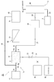
- FIG. 1 is a circuit diagram showing a schematic configuration of a valuable material generating system including a culture apparatus according to a first embodiment of the present invention.
- FIG. 2 is a circuit diagram showing a schematic configuration of a valuable material generating system including a culture apparatus according to a second embodiment of the present invention.
- FIG. 3 is a circuit diagram showing a schematic configuration of a valuable material generating system including a culture device according to a third embodiment of the present invention.
- FIG. 4 is a circuit diagram showing a valuable material generating system including a culture device according to a fourth embodiment of the present invention in a normal operation mode.
- FIG. 5 is a circuit diagram showing a valuable material generating system including a culture device according to a fourth embodiment of the present invention in a rapid dilution operation mode.
- FIG. 6 is a circuit diagram showing a valuable material generating system including a culture device according to a fourth embodiment of the present invention in a low biomass operation mode.
- FIG. 7 is a circuit diagram showing a valuable material generating system including a culture device according to a fourth embodiment of the present invention in a state recovery operation mode.
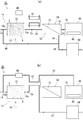
- FIG. 8A is a circuit diagram showing a part of the valuable material generating system including the culture apparatus according to the fifth embodiment of the present invention in the normal operation mode.
- FIG. 8B is a circuit diagram showing a part of the culture system including the culture apparatus according to the fifth embodiment in the rapid dilution operation mode.
- FIG. 9 is a circuit diagram showing a valuable material generating system including a culture apparatus according to a sixth embodiment of the present invention in a rapid dilution operation mode.
- FIG. 10 is a circuit diagram showing a schematic configuration of a valuable material generating system including a culture device according to a seventh embodiment of the present invention.
- FIG. 11 is a circuit diagram showing a schematic configuration of a valuable material generating system including a culture device according to an eighth embodiment of the present invention.
- FIG. 1 shows a valuable material generating system 1 according to the first embodiment of the present invention.
- the valuable material generation system 1 includes a culture device 1x and a subsequent device 1y.
- the culture apparatus 1x includes a culture tank 10 and a culture liquid source 12.
- the succeeding apparatus 1y includes an extraction storage tank 84 (bleed tank), a distillation tower 80 (extraction unit), and a drainage processing unit 8.
- the culture solution 2 is stored in the culture tank 10.
- the gas-utilizing microorganism 9 is cultured in the culture solution 2.
- the gas-assimilating microorganism 9 for example, anaerobic bacteria disclosed in JP-A-2014-050406, JP-A-2004-504058, etc. in addition to Patent Document 1 (US Publication US2013 / 0065282) are used. Can do.
- Valuables such as ethanol (C 2 H 5 OH) are synthesized from the substrate gas by the fermentation action of the gas-utilizing microorganism 9.
- Substrate gas components (predetermined components) used for fermentation of the gas assimilating microorganism 9 are mainly carbon monoxide (CO) and hydrogen (H 2 ). Examples of valuable materials include ethanol, butanol, acetic acid or acetate, and other organic compounds.
- the culture solution 2 in the culture tank 10 is stirred by a stirrer 16. Therefore, the gas assimilating microorganisms 9 are uniformly dispersed throughout the culture solution 2.
- a culture solution source 12 is connected to the culture tank 10.
- the culture solution source 12 stores a stock solution 2S of the culture solution 2. That is, the culture solution 2 before the gas assimilating microorganism 9 is mixed is stored. Most of the culture stock solution 2S is water (H 2 O), and nutrients such as vitamins and phosphoric acid are dispersed or dissolved therein.
- a stock solution supply path 14 extends from the culture solution source 12. This stock solution supply path 14 is connected to the solution supply port 10 p of the culture tank 10.
- a liquid feed pump 13 is provided in the middle of the stock solution supply path 14.
- a substrate gas source 3 is connected to the culture tank 10. Although detailed illustration is omitted, the substrate gas source 3 is configured in a waste treatment facility for treating industrial waste and the like. In other words, the culture apparatus 1x and thus the valuable material generation system 1 of this embodiment are incorporated in the waste treatment system.
- the substrate gas source 3 has a melting furnace, in which the waste is burned by high-concentration oxygen gas and decomposed to a low molecular level. Finally, an anaerobic substrate gas containing carbon monoxide (CO), hydrogen (H 2 ), carbon dioxide (CO 2 ) and the like is generated.
- the production flow rate and composition of the substrate gas depend on the type and amount of waste and are unstable.
- a gas supply path 31 extends from the substrate gas source 3.
- the gas supply path 31 is connected to the gas supply port 10q at the bottom of the culture tank 10.
- a gas flow meter 32 and a gas sensor 33 are provided in the middle of the gas supply path 31.
- the gas flow meter 32 measures the flow rate of the gas passing through the gas supply path 31.
- the gas sensor 33 is configured by gas chromatography or the like, and measures the composition (component, partial pressure, etc.) of the gas passing through the gas supply path 31.
- a discharge port 10e (discharge unit) is provided at, for example, the middle or bottom of the culture tank 10.
- a discharge path 22 extends from the discharge port 10e to the succeeding apparatus 1y.
- An extraction storage tank 84 is disposed at the downstream end of the discharge path 22.
- the culture tank 10 and the extraction storage tank 84 are connected via the discharge path 22.
- a liquid feed pump 23 is provided in the middle of the discharge path 22.
- the liquid feed pump 23 is configured by an inverter pump capable of output control.
- the discharge adjusting unit 21 is configured by the liquid feed pump 23 and the like in the discharge path 22.
- a flow rate control valve (not shown) may be provided in the discharge path 22.
- the discharge adjusting unit 21 may include a flow control valve.
- the discharge adjusting unit 21 may include a controller (control means) that controls the liquid feed pump 23 and / or the flow rate control valve.
- the discharged culture solution 2a from the culture tank 10 is stored.
- a delivery path 81 is drawn from the extraction storage tank 84.
- a liquid feed pump 85 is provided in the delivery path 81. Back flow is prevented by the liquid feed pump 85.
- the delivery path 81 is connected to the middle part of the distillation column 80.
- An extraction liquid path 82 extends from the upper end of the distillation column 80.
- a discharge path 83 extends from the bottom of the distillation column 80.
- the discharge path 83 is continuous with the drainage processing unit 8.
- the drainage processing unit 8 includes a drainage anaerobic processing unit, an aerobic processing unit, and the like.
- the culture stock solution 2S is introduced from the culture liquid source 12 into the culture tank 10, and the gas-assimilating microorganism 9 is cultured in the culture liquid 2 of the culture tank 10.
- the gas-assimilating microorganism 9 is uniformly dispersed throughout the culture solution 2.
- a substrate gas (CO, CO 2 , H 2, etc.) generated from waste in the substrate gas source 3 is introduced into the culture tank 10 through the gas supply path 31, and the substrate gas is introduced into the culture solution 2 of the culture tank 10. To melt.
- the above stirring can promote dissolution of the substrate gas in the culture solution 2.
- the gas assimilating microorganism 9 in the culture solution 2 performs fermentation and generates valuable materials such as ethanol from the substrate gas.
- a gaseous component such as CO 2 is also generated by fermentation.
- CO 2 is introduced from the gas supply passage 31, CO 2 produced by fermentation, unused CO, gaseous components such as H 2 is discharged from the exhaust port 10g of the culture tank 10.
- These gaseous components may be returned to the substrate gas source 3 or may be burned and used as a heat source such as distillation.
- the gas-utilizing microorganism 9 is contained in the discharged culture medium 2a, and the gas-utilizing microorganism 9 is discharged from the culture tank 10 together with the culture liquid 2a. Since the gas assimilating microorganism 9 is growing in the culture solution 2, the concentration of the gas assimilating microorganism 9 in the culture solution 2 is maintained substantially constant.
- the supply state of the substrate gas and its components from the substrate gas source 3 depends on the type and amount of waste and tends to be unstable. That is, the supply flow rate of the substrate gas varies depending on the type and amount of waste to be burned. In addition, the composition of the substrate gas (components and partial pressure of each component, etc.) varies depending on the type of waste to be burned. Therefore, the supply state of the substrate gas is monitored by the flow meter 31 and the gas sensor 33. Then, the substrate gases or the predetermined component (CO, H 2, etc.) in accordance with the supply state of adjusting the discharge amount of the culture solution 2a from the culture tank 10.
- the supply flow rate of the substrate gas is measured by the flow meter 31. Further, the partial pressure of a predetermined component (CO, H 2, etc.) in the substrate gas is measured by the gas sensor 33. From these measurement results, the supply flow rate of the predetermined component to the culture tank 10 is obtained. When the supply flow rate of the predetermined component (CO, H 2, etc.) exceeds a predetermined value (during normal operation), the liquid supply amounts of the liquid supply pumps 13 and 23 are kept small as described above.
- a part of the culture solution 2 in the culture tank 10 may be quickly discharged from the discharge port 10e a little before.
- the discharge flow rate of the culture solution 2a After rapidly discharging the culture solution 2a by an amount corresponding to the decrease in the supply flow rate, it is preferable to return the discharge flow rate of the culture solution 2a to the same level as during normal operation. In short, it is preferable not to continuously discharge a large amount of the culture solution 2a during the substrate gas supply abnormality period but to temporarily discharge a large amount of the culture solution 2a in advance or before the occurrence of the substrate gas supply abnormality.
- the gas-utilizing microorganism 9 in the culture solution 2a is also rapidly discharged from the culture tank 10. Accordingly, the number of gas-utilizing microorganisms 9 in the culture tank 10 is reduced. Thereby, the intake amount of the substrate gas for each individual of the gas-assimilating microorganism 9 can be secured. Therefore, it is possible to prevent all the individuals of the gas assimilating microorganisms 9 from being uniformly debilitated and to avoid being killed. Further, a new culture stock solution 2S is replenished from the culture solution source 12 to the culture tank 10 through the stock solution supply path 14 (rapid replenishment path). Preferably, the culture stock solution 2S is supplemented by the amount discharged.
- the gas-utilizing microorganism 9 can be stably cultured. Then, when the supply flow rate of the substrate gas or its predetermined components (CO, H 2, etc.) is restored, the fermentation by the gas assimilating microorganism 9 is rapidly restored and the growth proceeds.
- the substrate gas or its predetermined components CO, H 2, etc.
- the replenishment amount of the culture stock solution 2S is also maintained at the increased value until the end of the culture.
- the concentration of the gas-utilizing microorganism is stabilized at a lower value than before the start of rapid discharge.
- the discharged culture solution 2a is temporarily stored in the extraction storage tank 84 via the discharge path 22.
- the discharged culture solution 2a contains biomass such as a living body or a skeleton of the gas-assimilating microorganism 9, and valuable materials such as ethanol generated by fermentation in the culture tank 10.
- a part of the culture solution 2 a in the extraction storage tank 84 is introduced into the distillation tower 80 via the delivery path 81. And it distills in the distillation tower 80, and ethanol (valuable material) is extracted. Ethanol is discharged from the upper end of the distillation column 80 to the extraction liquid path 82 and is subjected to various uses through a purification process and the like.
- extraction can be performed as appropriate according to the processing capacity of the distillation column 80, the demand for ethanol, and the like, and the distillation column 80 exceeds its capacity. Can be avoided.
- the extraction residual liquid 2d At the bottom of the distillation column 80, the extraction residual liquid 2d accumulates.
- the extraction residual liquid 2d contains biomass at a high concentration.
- This extraction residual liquid 2d is sent from the lower end of the distillation tower 80 to the drainage treatment section 8 via the discharge path 83.
- the extraction residual liquid 2d is subjected to anaerobic treatment or aerobic treatment, whereby the biomass is decomposed.
- the biomass may be separated and used as fuel (heat source) in the distillation column 80 or the like.
- FIG. 2 shows a second embodiment of the present invention.
- the valuable material generation system 1B of the second embodiment includes a separation unit 50 (biomass concentration unit).
- the separation unit 50 includes a filter unit 59, a concentration storage tank 54, and a circulation path 58.
- the filter unit 59 includes a filter (separation membrane) 51.
- As the filter 51 a hollow fiber is used.
- the filter 51 divides the interior of the filter unit 59 into a transmission chamber 52 and a non-transmission chamber 53.
- the culture tank 10 and the concentration storage tank 54 are connected by the discharge path 22.
- the culture medium 2a discharged from the culture tank 10 is stored as the medium concentration culture liquid 2b.
- the concentration storage tank 54 and the extraction storage tank 84 are connected by the delivery path 28.
- the circulation path 58 includes an outward path 55 and a return path 56 (reconcentration return path).
- the concentration storage tank 54 and the filter unit 59 are connected to each other via an outward path 55 and a return path 56.
- the concentration storage tank 54 and the filter unit 59 are provided in the circulation path 58.
- the forward path 55 is drawn from the inside of the medium concentrated culture solution 2 b in the concentration storage tank 54 and continues to the inlet port of the non-permeation chamber 53 of the filter unit 59.
- a liquid feed pump 57 is provided in the middle of the forward path 55.
- the return path 56 extends from the outlet port of the non-permeation chamber 53 and continues to the concentration storage tank 54.
- the concentration storage tank 54 may not have a large volume. When the total volume of the reciprocating paths 55 and 56 and the non-permeation chamber 53 is more than a certain level, the concentration storage tank 54 may be omitted (see FIG. 3).
- the filter unit 59 and the culture tank 10 are connected via a diluent return path 41.
- the diluent return path 41 extends from the outlet port of the permeation chamber 52 and continues to the return port 10r of the culture tank 10.
- a liquid return pump 42 is provided in the diluted liquid return path 41. By providing the concentration reservoir 54, the pressure fluctuation of the liquid return pump 42 can be reduced.
- the discharged culture solution 2a from the culture tank 10 is temporarily stored as the culture solution 2b in the concentration storage tank 54.
- the culture solution 2b is circulated between the concentration reservoir 54 and the filter unit 59, whereby the gas-assimilating microorganism 9 is concentrated.
- the culture solution 2 b is introduced into the non-permeation chamber 53 of the filter unit 59 by driving the liquid feeding pump 57.
- the liquid component in the non-permeable chamber 53 can pass through the filter 51 and move to the permeable chamber 52.
- the living body of the gas assimilating microorganism 9 in the liquid, biomass such as carcass, and other solid components are prevented from passing through the filter 51.
- the medium concentrated culture solution 2 b is separated into the diluted culture solution 2 c in the permeation chamber 52 and the concentrated culture solution 2 e in the non-permeation chamber 53.
- the diluted culture solution 2c has a sufficiently lower biomass concentration than the culture solution 2 in the culture tank 10, and preferably contains almost no biomass.
- the concentrated culture solution 2 e has a higher biomass concentration than the culture solution 2 in the culture tank 10. That is, the diluted culture solution 2c is a biomass dilution solution in which biomass is diluted (including complete removal), and the concentrated culture solution 2e is a biomass highly concentrated solution in which biomass is highly concentrated.
- the diluted culture solution 2 c is returned to the culture tank 10 through the diluted solution return path 41 by the operation of the solution return pump 42.
- the supply flow rate of the culture stock solution 2S can be reduced by the return flow rate of the diluted culture solution 2c, and waste of the culture solution can be suppressed.
- the substrate gas supply is abnormal, it is possible to suppress an increase in the supply flow rate of the culture stock solution 2S by returning a larger amount of the diluted culture solution 2c to the culture tank 10 than during normal operation. Therefore, the composition change of the liquid component of the culture solution 2 is small, and the risk of the gas-utilizing microorganism 9 being killed by shock can be reduced.
- the storage tank 54 for concentration is large and the residence time of the culture medium 2b in the tank 54 is long, it is preferable to make the biomass concentration of the diluted culture medium 2c in the filter unit 59 sufficiently low, almost zero. It is more preferable. Thereby, even if the gas assimilating microorganism 9 dies in the culture solution 2b, it is possible to prevent the carcass of the gas assimilating microorganism 9 from being mixed into the culture tank 10 together with the diluted culture solution 2c.
- the composition of the liquid component of the culture solution 2 in the culture tank 10 does not necessarily match the composition of the culture stock solution 2S, and there are components that are consumed or produced by the life activity of the gas-utilizing microorganism 9. . Therefore, if the supply amount of the culture stock solution 2S is too large, the gas assimilating microorganisms 9 may be shocked by sudden changes in the environment.
- the concentrated culture solution 2 e is returned to the concentration storage tank 54 via the return path 56. Therefore, the medium concentrated culture solution 2b in the concentration storage tank 54 is a mixture of the discharged culture solution 2a and the concentrated culture solution 2e (biomass highly concentrated solution), and the biomass concentration ( High gas-utilizing microorganism concentration). That is, in the medium concentrated culture solution 2b, the biomass containing the living body and the carcass of the gas-utilizing microorganism 9 is more concentrated than the culture solutions 2 and 2a. A portion of the concentrated culture solution 2 b in the concentration reservoir 54 is stored in the extraction reservoir 84 via the delivery path 28.
- the culture solution 2a rapidly discharged when the substrate gas supply is abnormal can be stored via the concentration reservoir 54.
- the delivery flow rate U 4 from the concentration storage tank 54 to the extraction storage tank 84 is made smaller than the discharge flow rate U 0 of the culture solution 2a (U 0 > U 4 ). Thereby, the storage amount of the medium concentrated culture solution 2b in the concentration storage tank 54 can be secured. Further, the biomass concentration in the medium concentrated culture solution 2b is (U 0 / U 4 ) times the biomass concentration in the culture solutions 2 and 2a.
- the flow in the non-permeable chamber 53 can be increased, and the filter 51 can be prevented from being clogged.
- the concentration storage tank 54 of FIG. 2 may be omitted. It is sufficient that at least the filter unit 59 of the filter unit 59 and the concentration storage tank 54 is provided in the circulation path 58. As shown in FIG. 3, in the valuable material generating system 1 ⁇ / b> C of the third embodiment, the concentration storage tank 54 in the second embodiment (FIG. 2) is omitted, and a merging portion 58 c is provided instead. In the merging portion 58c, the discharge path 22 and the return path 56 are joined directly (not via the concentration storage tank 54). The forward path 55 extends from the junction 58c. The delivery path 28 is branched from the middle part of the return path 56. The delivery path 28 is connected to the extraction storage tank 84.
- the discharged culture solution 2a from the culture tank 10 is mixed with the culture solution 2e from the return path 56 at the junction 58c via the discharge path 22.
- the mixed culture solution is circulated through the circulation path 58 in the order of the forward path 55, the filter unit 59, and the return path 56, and is separated into the diluted culture solution 2c and the concentrated culture solution 2e in the filter unit 59.
- the diluted culture solution 2c is returned to the culture tank 10 through the diluted solution return path 41.
- a part of the concentrated culture solution 2e is diverted to the delivery path 28 and stored in the extraction storage tank 84, and is further subjected to ethanol extraction by the distillation tower 80.
- the remainder of the concentrated culture solution 2e goes to the junction 58c via the return path 56.
- the culture apparatus 1x of the valuable material generation system 1D includes a culture tank 10, a culture solution source 12, a filter unit 59, and a diluent storage tank 40.
- Two (a plurality of) substrate gas sources 3 ⁇ / b> A and 3 ⁇ / b> B are connected to the culture tank 10 through a gas supply path 31.
- the valuable material generation system 1D has four operation modes corresponding to the supply state of the substrate gas or its predetermined components (CO, H 2, etc.).
- the connection state between the components 10, 12, 59, 40, and 84 of the system 1D changes for each operation mode.
- the constituent elements 10, 12, 59, 40, and 84 are connected by piping so as to be compatible with all the operation modes.
- the circuit configuration is changed by opening and closing some pipes with valves or turning on and off the liquid feed pump.
- valves and pumps is omitted.
- (1) Normal operation mode As shown in FIG. 4, when the supply state of the substrate gas from the two substrate gas sources 3A and 3B is smooth, the normal operation mode is executed.
- the culture solution source 12 and the culture tank 10 are connected, and the culture tank 10 and the filter unit 59 are connected.
- the outlet port of the non-permeation chamber 53 is connected to the extraction storage tank 84 (bleed tank) via the concentrate feed path 28 and to the liquid supply port 10p of the culture tank 10 via the concentrate return path 44.
- the outlet port of the permeation chamber 52 is connected to the diluent storage tank 40 (permeate tank) via the diluent storage path 24.
- the volume of the diluent storage tank 40 is preferably equal to or greater than the volume of the culture tank 10.
- a culture stock solution 2S having a constant flow rate is supplied from the culture liquid source 12 to the culture tank 10, and the gas-utilizing microorganism 9 is cultured in the culture liquid 2 of the culture tank 10 (culture process).
- the discharge culture solution 2a of a fixed flow rate is discharged
- the drained culture solution 2a is separated into a diluted culture solution 2c and a concentrated culture solution 2e in the filter unit 59 (separation step).
- the filter 51 of the filter unit 59 is made of, for example, a cross-flow type UF (ultrafiltration) film.
- a circulation path 58 similar to that of the second and third embodiments (FIGS. 2 and 3) may be provided, and the filter unit 59 may be disposed in the circulation path 58.
- the diluted culture solution 2c (filtrate) from the filter unit 59 has a biomass concentration of the gas-assimilating microorganism 9 or the like being substantially zero.
- the diluted culture solution 2c is stored in the diluted solution storage tank 40 through the diluted solution storage path 24 (a diluted solution storage step).
- the composition of the diluted culture solution 2c in the diluted solution storage tank 40 substantially matches the composition of the liquid components in the culture tank 10.
- a part of the concentrated culture solution 2 e from the non-permeation chamber 53 is stored in the extraction storage tank 84 through the concentrate delivery path 28.
- the concentrated culture solution 2e in the extraction storage tank 84 is sent to the distillation tower 80 and used for ethanol extraction.
- the remainder (preferably most) of the concentrated culture solution 2e from the non-permeation chamber 53 is returned to the culture tank 10 together with the culture stock solution 2S (fresh media) from the culture solution source 12 via the concentrate return path 44. Therefore, as a whole, the discharge rate of the gas assimilating microorganisms 9 in the culture solution 2 of the culture tank 10 is slower than the discharge rate of the liquid components of the culture solution 2, and the culture solution 2 is kept at a high biomass density.
- the total of the return flow rate of the concentrated culture solution 2e and the supply flow rate of the culture stock solution 2S balances with the discharge flow rate of the discharged culture solution 2a, so that the amount of the culture solution 2 in the culture tank 10 is maintained constant.
- the rapid dilution operation mode is executed as shown in FIG.
- the discharge port 10e of the culture tank 10 and the extraction storage tank 84 are directly communicated with each other by the quick discharge path 27 (discharge control unit). Further, the diluting liquid storage tank 40 and the supply port 10p of the culture tank 10 are communicated with each other by a quick replenishment path 43.
- emission culture solution 2a from the culture tank 10 is increased temporarily. That is, the culture solution 2 is rapidly discharged from the culture tank 10 (rapid discharge step). As a result, the number of gas-utilizing microorganisms 9 in the culture tank 10 is reduced.
- the degree of decrease of the gas-assimilating microorganism 9 is determined according to the degree of decrease in the supply flow rate of the substrate gas.
- the supply flow rate of the substrate gas is halved, about half of the culture solution 2 is discharged, and the gas-assimilating microorganism 9 in the culture tank 10 is halved.
- the intake amount of the substrate gas for each individual of the gas assimilating microorganisms 9 can be maintained substantially the same as the value in the normal operation mode. As a result, it can be avoided that all individuals of the gas-utilizing microorganism 9 are uniformly weakened and killed.
- the discharged culture solution 2a rapidly discharged from the culture tank 10 is sent to the extraction storage tank 84 through the quick discharge path 27. Note that the quick discharge path 27 may pass through the non-permeation chamber 53 of the filter unit 59.
- the diluted culture solution 2c in the diluent storage tank 40 is returned to the culture tank 10 through the quick supply path 43 (stored dilution solution quick supply step). . Therefore, it is not necessary to increase the supply flow rate of the culture stock solution 2S.
- the gas-assimilating microorganism concentration of the culture solution 2 in the culture tank 10 can be diluted. Since the diluted culture solution 2c has substantially the same composition as the liquid components of the culture solution 2, the liquid composition of the culture solution 2 does not change suddenly even when supplied in large quantities to the culture tank 10.
- the gas assimilating microorganism 9 from being damaged by the sudden change in the liquid composition.
- the biomass concentration of the diluted culture solution 2c By setting the biomass concentration of the diluted culture solution 2c to approximately 0, it is possible to prevent the carcass of the gas-assimilating microorganism 9 from being mixed into the culture tank 10.
- the biomass concentration in the diluted culture solution 2c (filtrate) from the filter unit 59 is not 0, the supernatant of the diluted culture solution 2c is precipitated by the precipitation of the biomass during the storage period in the diluent storage tank 40. The supernatant may be rapidly replenished to the culture tank 10 in the rapid dilution operation mode.
- the filter 51 can be reduced in size and construction cost can be suppressed.
- the filter 51 is enlarged in order to ensure rapidity (mass permeation of the filter 51) when the discharged culture solution 2a is discharged in large quantities. Construction costs will increase.
- the rapid dilution operation mode that is, the rapid discharge operation of the discharged culture solution 2a and the rapid replenishment operation of the diluted culture solution 2c are preferably completed within several minutes to several tens of minutes.
- the diluted culture solution 2c obtained in the separation step in the filter unit 59 is directly returned to the culture vessel 10 without being sent to the diluent storage tank 40.
- a part of the concentrated culture solution 2e obtained in the separation step is returned to the non-permeation chamber 53 by the circulation path 58, and the remainder of the concentrated culture solution 2e is sent to the extraction storage tank 84 and then to the subsequent device 1y. Accordingly, as a whole, the discharge rate of the gas-utilizing microorganism 9 in the culture solution 2 is faster than the discharge rate of the liquid components of the culture solution 2.
- the gas assimilating microorganism 9 grows in the culture tank 10, the gas assimilating microorganism 9 corresponding to the proliferation is discharged from the culture tank 10, so that the inside of the culture tank 10 is brought into a low biomass state. Can be maintained. Therefore, even if the supply flow rate of the substrate gas is small, the gas-assimilating microorganism 9 can be stably cultured, and the gas-assimilating microorganism 9 can be prevented from being killed or metabolized.
- the state recovery operation mode is executed. As shown in FIG. 7, in the state recovery operation mode, the permeation chamber 52 and the diluent storage tank 40 are communicated by the diluent storage path 24, and the non-permeation chamber 53 and the extraction storage tank 84 are shut off. The outlet port of the non-permeation chamber 53 is communicated only with the liquid supply port 10p of the culture tank 10 through the concentrated liquid return path 44. Therefore, the entire amount of the concentrated culture solution 2e obtained in the separation step in the filter unit 59 is returned to the culture tank 10 through the concentrate return path 44.
- the time from when the culture solution 2b is discharged from the culture vessel 10 to when the culture solution 2b is converted into the concentrated culture solution 2e and returned to the culture vessel 10 is the time during which the gas-assimilating microorganism 9 does not die in an environment without substrate gas. Is preferably within 1 minute, and at most 3 hours. Further, the entire amount of the diluted culture solution 2c is stored in the diluted solution storage tank 40.
- the supply flow rate of the substrate gas to the culture tank 10 is increased while monitoring the state of the culture solution 2 (concentration of required components) in the culture tank 10.
- the concentration of the gas-utilizing microorganism 9 in the culture solution 2 can be rapidly increased by growing.
- the concentration of the gas-utilizing microorganism 9 increases, the supply flow rate of the substrate gas is increased.
- the concentration of the gas-assimilating microorganism 9 is proportional to the supply flow rate of the substrate gas.
- the input amount of the culture stock solution 2S (fresh media) from the culture liquid source 12 is adjusted so that the liquid composition (eg, acetic acid concentration) of the culture liquid 2 is constant.
- FIG. 8 shows a fifth embodiment of the present invention.
- the cooler 46 liquid temperature adjustment part
- a heat exchanger 47 is provided between the quick replenishment path 43 and the quick discharge path 27 in the rapid dilution operation mode of the system 1E.
- a heater 49 is provided in the quick replenishment path 43 closer to the culture tank 10 than the heat exchanger 47.
- the diluted culture solution 2c stored in the diluent storage tank 40 is cooled with the cooler 46, and the temperature of the culture tank 10 is shown. Make it cooler.
- the set temperature of the cooler 46 is a temperature at which organisms such as bacteria cannot survive, or a temperature at which life activity such as metabolism and reproduction can be disabled or suppressed, and a temperature at which the diluted culture solution 2c does not freeze.
- the temperature is set to about 0 ° C. to 20 ° C., preferably about 4 ° C. Thereby, it is possible to suppress or prevent the growth of spoilage bacteria in the diluted culture solution 2c, and to prevent the generation of odor.
- the diluted culture solution 2c passing through the rapid replenishment path 43 and the discharged culture solution 2a passing through the rapid discharge path 27 are heat exchangers. At 47, heat is exchanged. By diluting the heat, the diluted culture solution 2c can be warmed to approach the temperature of the culture tank 10. By using the discharged culture medium 2a as a heating source, the load on the heater 49 described later can be reduced.
- the diluted culture solution 2c is further heated by the heater 49.
- the temperature of the diluted culture solution 2 c can be made sufficiently close to the temperature of the culture solution 2 in the culture tank 10, and preferably about the same temperature as the culture solution 2.
- the diluted culture solution 2 c is supplied to the culture tank 10 and mixed with the culture solution 2.
- the change in the temperature of the culture solution 2 can be sufficiently reduced. Therefore, it is possible to prevent the gas assimilating microorganism 9 in the culture tank 10 from being damaged by the change in the liquid temperature.
- a heater may be used in place of the cooler 46 as the liquid temperature adjusting unit of the diluent storage tank 40.
- the diluted culture solution 2c in the diluted solution storage tank 40 may be heated to a temperature higher than that of the culture tank 10 by this heater.
- the set temperature for heating is preferably 50 ° C. to 100 ° C. By setting the temperature to 50 ° C. or higher, organisms such as bacteria can be made non-viable, or life activities such as metabolism and reproduction can be made impossible or suppressed. Moreover, it can prevent that the diluted culture solution 2c boils or the component in the diluted culture solution 2c denatures by setting to less than 100 degreeC.
- a heater is provided in the diluent storage tank 40, it is preferable to provide a cooler instead of the heater 49 in the quick replenishment path 43 between the heat exchanger 47 and the culture tank 10.
- FIG. 9 shows a sixth embodiment of the present invention.
- This embodiment is a modification of the rapid dilution operation mode.
- the backwashing path 45 is branched from the rapid replenishment path 43.
- the backwash path 45 passes through the filter unit 59 in the order of the permeation chamber 52 and the non-permeation chamber 53, and joins the quick refill path 43 again.
- a flow rate control valve 48 is provided in the quick replenishment path 43 between the branch part and the junction part of the backwash path 45.
- a part of the diluted culture solution 2c from the diluent storage tank 40 is diverted from the quick replenishment path 43 to the backwash path 45 and flows back through the filter unit 59.
- the filter 51 can be backwashed, and clogging of the filter 51 can be reduced or eliminated.
- the diluted culture solution 2c after backwashing merges with the diluted culture solution 2c that travels straight through the rapid replenishment path 43 and is introduced into the culture tank 10.
- the flow rate for backwashing can be adjusted by the flow rate control valve 48. Note that the whole diluted culture solution 2c may flow back through the filter unit 59.
- an opening / closing valve may be provided in the quick replenishment path 43.
- FIG. 10 shows a seventh embodiment of the present invention.
- the valuable material generation system 1G includes a culture device 1x and a subsequent device 1y.
- the culture apparatus 1x includes a culture tank 10 and a biomass concentration unit 50G (separation unit).
- the subsequent device 1y includes a distillation column 80 (extraction unit) and a drainage processing unit 8.
- the culture solution 2 is stored in the culture tank 10.
- the gas-utilizing microorganism 9 is cultured in the culture solution 2.
- the microorganism 9 for example, anaerobic bacteria disclosed in Japanese Patent Application Laid-Open No. 2014-050406, Japanese Patent Application Laid-Open No. 2004-504058 and the like can be used in addition to Patent Document 1 (US Publication US2013 / 0065282).
- Valuables such as ethanol (C 2 H 5 OH) are synthesized from the substrate gas by the fermentation action of the microorganism 9.
- Substrate gas components (predetermined components) used for fermentation of the microorganism 9 are mainly carbon monoxide (CO) and hydrogen (H 2 ). Examples of valuable materials include ethanol, butanol, acetic acid or acetate, and other organic compounds.
- the culture solution 2 in the culture tank 10 is stirred by a stirrer 16. Therefore, the gas assimilating microorganisms 9 are uniformly dispersed throughout the culture solution 2.
- a culture solution source 12 is connected to the culture tank 10.
- the culture solution source 12 stores a stock solution 2S of the culture solution 2. That is, the culture solution 2 before the gas assimilating microorganism 9 is mixed is stored. Most of the culture stock solution 2S is water (H 2 O), and nutrients such as vitamins and phosphoric acid are dispersed or dissolved therein.
- a stock solution supply path 14 extends from the culture solution source 12. This stock solution supply path 14 is connected to the solution supply port 10 p of the culture tank 10.
- a substrate gas source 3 is connected to the culture tank 10.
- a gas supply path 31 extends from the substrate gas source 3.
- the gas supply path 31 is connected to the gas supply port 10q at the bottom of the culture tank 10.
- the substrate gas source 3 is configured in a waste treatment facility for treating industrial waste and the like.
- the culture apparatus 1x and thus the valuable material generation system 1G of this embodiment are incorporated in the waste treatment system.
- the substrate gas source 3 has a melting furnace, in which the waste is burned with high-concentration oxygen gas and decomposed to a low molecular level.
- an anaerobic substrate gas containing carbon monoxide (CO), hydrogen (H 2 ), carbon dioxide (CO 2 ) and the like is generated.
- the production flow rate and composition of the substrate gas depend on the type and amount of waste and are unstable.
- the biomass concentrating unit 50G is configured by a separator including a filter 51 (separation membrane).
- a filter 51 separation membrane
- a hollow fiber membrane is used as the filter 51.
- the filter 51 defines a transmission chamber 52 and a non-transmission chamber 53.
- the culture tank 10 and the biomass concentrating part 50G are connected via the culture solution discharge path 22 and the diluted solution return path 41.
- the discharge path 22 extends from the discharge port 10 e at the middle or bottom of the culture tank 10 and continues to the inlet port of the non-permeation chamber 53.
- a liquid feed pump 23 is provided in the discharge path 22.
- the diluent return path 41 extends from the outlet port of the permeation chamber 52 and continues to the return port 10r of the culture tank 10.
- the dilution liquid return path 41 may be provided with a liquid return pump 42 (see FIG. 11).
- the concentrate delivery path 29 extends from the outlet port of the non-permeation chamber 53 to the succeeding apparatus 1y.
- the concentrated liquid delivery path 29 is connected to the middle part of the distillation column 80.
- An extraction liquid path 82 extends from the upper end of the distillation column 80.
- a discharge path 83 extends from the bottom of the distillation column 80.
- the discharge path 83 is continuous with the drainage processing unit 8.
- the drainage processing unit 8 includes a drainage anaerobic processing unit, an aerobic processing unit, and the like.
- a culture method by the above valuable material generation system 1G and, in turn, a valuable material generation method will be described.
- the culture solution 2 is placed in the culture tank 10, and the gas-utilizing microorganism 9 is cultured in the culture solution 2.
- the gas-assimilating microorganism 9 is uniformly dispersed throughout the culture solution 2.
- a substrate gas (CO, H 2 CO 2, etc.) generated from waste in the substrate gas source 3 is introduced into the culture tank 10 through the gas supply path 31, and the substrate gas is introduced into the culture solution 2 of the culture tank 10. Let it melt.
- the above stirring can promote dissolution of the substrate gas in the culture solution 2.
- the supply flow rate of the substrate gas from the substrate gas source 3 is not necessarily constant.
- the gas assimilating microorganism 9 in the culture solution 2 performs fermentation and generates valuable materials such as ethanol from the substrate gas.
- a gaseous component such as CO 2 is also generated by fermentation.
- CO 2 is introduced from the gas supply passage 31, CO 2 and produced by fermentation, unused CO, gaseous components such as H 2 is discharged from the exhaust port 10g of the culture tank 10.
- These gaseous components may be returned to the substrate gas source 3, or may be burned and used as a heat source such as distillation.
- exhaust culture solution 2 a By driving the liquid feeding pump 23, a part 2 a of the culture solution 2 in the culture tank 10 (hereinafter, appropriately referred to as “exhaust culture solution 2 a”) is discharged to the discharge path 22.
- This discharged culture solution 2a is sent to the biomass concentrating unit 50G via the discharge path 22.
- the culture solution 2a may be discharged continuously or intermittently or intermittently. You may carry out regularly and may carry out irregularly according to a culture
- the supply flow rate of the substrate gas from the substrate gas source 3 to the culture tank 10 and predetermined components (CO, H 2, etc.) in the substrate gas is monitored, and when the supply flow rate falls below a predetermined level, the culture solution 2a is discharged. You may decide to make it.
- the culture solution 2a may be discharged for the amount of growth of the gas-utilizing microorganism 9 in the culture tank 10.
- the concentration of the gas-assimilating microorganism 9 in the culture tank 10 may be monitored, and when the concentration exceeds a predetermined value, the culture solution 2a may be discharged, or the discharged culture solution 2a may be discharged according to the concentration. You may decide to adjust the flow volume of this (refer FIG. 11).
- the discharged culture solution 2a is introduced into the non-permeation chamber 53 of the biomass concentrating unit 50G via the discharge path 22.
- the liquid component in the culture solution 2 a passing through the non-permeation chamber 53 can pass through the filter 51 and move to the permeation chamber 52.
- the biomass such as the living body of the gas-assimilating microorganism 9 in the culture solution 2a, the carcass, and other solid components are prevented from passing through the filter 51. Therefore, the culture solution 2 a is separated into the diluted culture solution 2 c (permeate) in the permeation chamber 52 and the concentrated culture solution 2 e (non-permeation solution) in the non-permeation chamber 53.
- the diluted culture solution 2c has a sufficiently lower biomass concentration and thus the concentration of the gas-utilizing microorganism 9 than the discharged culture solution 2a and thus the culture solution 2 in the culture tank 10, and preferably contains almost no biomass.
- the biomass concentration of the diluted culture solution 2c in the present system 1G may be higher than the biomass concentration of the diluted culture solution 2c in the systems 1D to 1F (FIGS. 4 to 9).
- the concentrated culture solution 2e has a higher biomass concentration and thus a concentration of the gas-utilizing microorganism 9 than the discharged culture solution 2a and thus the culture solution 2 in the culture tank 10. That is, the gas-utilizing microorganism 9 is diluted (including removal) in the diluted culture solution 2c, and the gas-utilizing microorganism 9 is concentrated in the concentrated culture solution 2e.
- ⁇ Return process> The diluted culture solution 2 c is returned to the culture tank 10 through the diluted solution return path 41.
- ⁇ Replenishment process> Only the difference between the discharge flow rate U 0 of the discharge culture 2a and flow rate U 2 returns dilution culture 2c, supplementing the culture stock 2S in the culture tank 10 from the culture medium source 12.
- the biomass concentration in the concentrated culture solution 2e is U 0 / (U 0 -U 2 ) times the biomass concentration in the culture solutions 2 and 2a. Therefore, by adjusting the flow rate U 2 of the flow U 0 of the discharge broth 2a diluted culture 2c, it can be controlled concentration ratio in the biomass concentration unit 50G.
- the concentrated culture solution 2e is sent out from the culture apparatus 1x through the concentrate sending path 29 and is supplied to the subsequent process. Specifically, the concentrated culture solution 2 e is introduced into the distillation tower 80 through the concentrated solution delivery path 29.
- the concentrated culture solution 2e is distilled to extract ethanol (valuable material).
- the flow rate U 2 returns dilution culture 2c, and by reducing only can the flow rate of the culture stock 2S, can highest possible ethanol concentration in the culture solution 2, the ethanol extract of efficiency in turn distillation column 80 Can be increased.
- the extracted ethanol is discharged from the upper end of the distillation column 80 to the extraction liquid path 82 and is used for various purposes through a purification process and the like.
- the extraction residual liquid 2d At the bottom of the distillation column 80, the extraction residual liquid 2d accumulates.
- the extraction residual liquid 2d contains a high concentration of biomass such as a carcass of the gas assimilating microorganism 9.
- This extraction residual liquid 2d is sent from the lower end of the distillation tower 80 to the drainage treatment section 8 via the discharge path 83.
- the extraction residual liquid 2d is subjected to anaerobic treatment or aerobic treatment, whereby the biomass is decomposed.
- biomass may be aggregated and used as a fuel (heat source) for extraction of valuable materials.
- the gas-assimilating microorganism 9 contained in the discharged culture solution 2a can be concentrated and discharged from the culture apparatus 1x.
- a part of the liquid component in the discharged culture medium 2a can be separated from the gas assimilating microorganism 9 and returned to the culture tank 10 as a diluted culture liquid 2c. Therefore, the discharge flow rate of the culture solution 2 to the outside of the system can be reduced, and waste of the culture solution 2 can be suppressed.
- the replenishment flow rate of the culture stock solution 2S not only the cost can be reduced, but also the environment in the culture tank 10 (composition of the culture solution 2 and the like) can be maintained as constant as possible. It can be stably cultured.
- the composition of the liquid component of the culture solution 2 in the culture tank 10 does not necessarily match the composition of the culture stock solution 2S, and there are components that are consumed or produced by the life activity of the gas-utilizing microorganism 9. . Therefore, if the supply amount of the culture stock solution 2S is too large, the gas assimilating microorganisms 9 may be shocked by sudden changes in the environment.
- FIG. 11 shows an eighth embodiment of the present invention.
- the valuable material generation system 1H further includes a controller 60 (separation ratio adjusting unit) and a biomass concentration measuring device 61 (microorganism concentration measuring device).
- a liquid return pump 42 is provided in the diluted liquid return path 41.
- the biomass concentration measuring device 61 is provided in the discharge path 22 and measures the biomass concentration in the discharged culture solution 2a. As a result, the density
- the biomass concentration measuring device 61 for example, an optical concentration measuring device that irradiates the culture solution with light and measures the biomass concentration from the absorption rate or the like can be used. Thereby, the biomass concentration can be measured in real time.
- the biomass concentration measuring device 61 may be provided in the culture tank 10 and the concentration of the gas-assimilating microorganism 9 in the culture tank 10 may be directly measured.
- the controller 60 Based on the measured concentration information, the controller 60 adjusts the output of the liquid return pump 42, that is, the flow rate of the diluted culture solution 2c so that the concentration of the gas-utilizing microorganism 9 in the culture solution 2 becomes a predetermined value. . As a result, the separation ratio between the diluted culture solution 2c and the concentrated culture solution 2e in the biomass concentration unit 50G is adjusted. Further, the controller 60 adjusts the output of the liquid feeding pump 23 to balance the flow rate of the discharged culture solution 2a with the total flow rate of the return flow rate of the diluted culture solution 2c and the supply flow rate of the culture stock solution 2S. Thereby, the quantity of the culture solution 2 in the culture tank 10 is maintained at a predetermined level.
- the output of the liquid return pump 42 is increased.
- the amount of liquid that permeates the filter 51 in the biomass concentration unit 50G increases, and the return flow rate of the diluted culture solution 2c that does not contain the gas-assimilating microorganism 9 to the culture tank 10 increases.
- the output of the liquid feeding pump 23 is increased and the discharge flow rate of the culture liquid 2a is increased. For this reason, the extraction amount of the gas-utilizing microorganism 9 from the culture tank 10 increases. Therefore, the concentration of the gas-assimilating microorganism 9 in the culture tank 10 can be reduced.
- the output of the liquid return pump 42 is lowered.
- the amount of liquid that permeates the filter 51 in the biomass concentration unit 50G is reduced, and the return flow rate of the diluted culture solution 2c to the culture tank 10 is reduced.
- the output of the liquid feeding pump 23 is lowered to decrease the discharge flow rate of the culture solution 2a.
- the concentration of the gas-assimilating microorganism 9 in the culture tank 10 can be increased.
- the concentration of the gas-assimilating microorganism 9 in the culture tank 10 can be kept constant.
- the liquid feed pump By increasing the output of 23 and increasing the flow rate of the discharged culture medium 2a, the number of gas-utilizing microorganisms 9 in the culture tank 10 is reduced. Thereby, the gas-utilizing microorganism 9 can be prevented from being killed, and the gas-utilizing microorganism 9 can be stably cultured.
- the discharge amount adjustment of the culture solution 2a is performed based on the supply flow rate of the entire substrate gas, instead of being based on the supply flow rate of the predetermined component in the substrate gas.
- the gas supply path 31 only needs to have a flow meter 32, and the gas sensor 33 may be omitted.
- the supply amount of the substrate gas or the predetermined component may be adjusted based on the temperature and pressure of the substrate gas, the partial pressure of the predetermined component, etc.
- the extraction storage tank 84 may be omitted in the first embodiment (FIG. 1) and the like.
- the discharge path 22 may be connected to the distillation tower 80 without passing through the storage tank 84. Further, the discharge path 22 may be connected to the drainage processing unit 8 without passing through the storage tank 84 and the distillation tower 80.
- the discharge path 22 is connected to the inlet port of the non-permeate chamber 53 of the biomass concentrating unit 50 without the storage tank 84, and the outlet port of the non-permeate chamber 53 is connected to the storage tank 84.
- a solid-liquid separator such as a filter or a centrifugal separator may be disposed on the delivery paths 81 and 29 to prevent the solid component from being charged into the distillation tower 80. Thereby, the maintenance frequency of the distillation tower 80 can be lowered
- the concentrated culture solution 2e after concentration / separation of the microorganism 9 is returned to the culture tank 10 and the diluted culture solution 2c is transferred to the subsequent device, as in Patent Document 1
- the valuable material may be extracted by sending it to the 1y distillation column 80.
- the microorganism 9 is concentrated as in the systems 1G and 1H.
- the diluted culture solution 2c after separation may be returned to the culture tank 10 and the concentrated culture solution 2e may be sent to the subsequent device 1y.
- the diluted culture solution 2c (microbe dilution / exclusion solution) only needs to have a lower microorganism concentration than the concentrated culture solution 2e, and the diluted culture solution 2c may contain microorganisms having a lower concentration than the non-permeate solution 2.
- a plurality of embodiments may be combined with each other. For example, in the first to seventh embodiments (FIGS. 1 to 10), as in the eighth embodiment (FIG. 11), a controller 60 and a biomass concentration measuring device 61 may be added.
- the present invention can be applied to, for example, an ethanol production system that synthesizes ethanol from carbon monoxide generated by incineration of industrial waste.
Abstract
Description
上掲特許文献1の培養装置は、微生物を培養液より長い時間培養槽に滞在させるとき有効である。しかし、例えば微生物の増殖の程度や基質ガスの供給状況等に応じて安定的な培養のために、一部の微生物を培養槽から排出すべき必要が生じた場合、その一部の微生物を含む培養液ごと排出する必要がある。したがって、微生物を培養液よりも速く系外へ排出することはできない。すなわち、微生物の排出速度は、培養液の排出速度を上回ることができない。微生物の排出速度を上げるには培養液の排出速度を上げる必要がある。そのため、培養液の排出量が多くなるという不都合がある。
本発明は、上記事情に鑑み、ガス資化性微生物を、基質ガスの供給状態の変動に拘わらず、安定的に培養することを第1の課題とする。
また、本発明は、培養槽内の微生物を安定的に培養するとともに、培養槽から微生物の一部を排出すべき必要が生じた場合に培養液の無駄を防止することを第2の課題とする。 When the inventors tried to culture this kind of gas-utilizing microorganism, the supply amount of the substrate gas and a certain component in the gas was lowered for some reason or the supply was stopped. When the living environment deteriorated, there was a problem that almost all microorganisms were uniformly debilitated and easily killed.
The culture apparatus of the above-mentioned
In view of the above circumstances, a first object of the present invention is to stably culture a gas-assimilating microorganism regardless of changes in the supply state of a substrate gas.
In addition, a second object of the present invention is to stably culture microorganisms in a culture tank and prevent waste of a culture solution when it is necessary to discharge a part of the microorganisms from the culture tank. To do.
培養槽の培養液で前記ガス資化性微生物を培養する工程と、
前記基質ガスを前記培養槽に供給する工程と、
前記ガス資化性微生物を含む前記培養液の一部を排出培養液として前記培養槽から排出する量(排出量)を調節する工程と、
を備え、前記排出量調節工程において前記基質ガス又は前記所定成分の前記培養槽への供給流量が所定値以下になるとき事前に、又は前記所定値以下になったときは、前記培養液を前記培養槽から急速排出することを特徴とする。
この方法によれば、基質ガス又はその所定成分の供給状態が悪化したときは、培養槽の培養液ひいてはガス資化性微生物を急速排出することによって、培養槽内のガス資化性微生物の個体数を減らすことができる。これによって、培養槽内のガス資化性微生物の各個体あたりの基質ガスの摂取量を確保できる。この結果、培養槽内のガス資化性微生物が死滅するのを回避でき、ガス資化性微生物を安定的に培養することができる。前記培養槽から培養液をある程度排出した後は、排出量を増大前の大きさ付近まで戻すことが好ましい。そして、基質ガス又は前記所定成分の供給状態が回復したときは、ガス資化性微生物による発酵が急速に復活し、増殖も進む。
ここで、「供給流量が所定値以下になる」とは、供給流量が、通常運転モードの例えば3割~8割程度以下、好ましくは5割程度以下になることを言う。或いは、基質ガス供給装置がn台(nは2以上の整数)有る場合において、m台(mは1以上n以下の整数)の基質ガス供給装置がトラブルやメンテナンスで運転停止等になることで、供給流量が通常運転モードの例えば(n-m)/n倍(基質ガス供給装置ごとの通常運転モードでの供給流量が互いに等しい場合)になることであってもよい。
「基質ガス又は所定成分の供給状態」とは、基質ガスの流量、基質ガスの所定成分の流量、前記所定成分の分圧、基質ガスの圧力、基質ガスの温度等を含む。「所定成分」は、前記基質ガスの成分のうち、前記ガス資化性微生物の生存、発酵、増殖等の生命活動に特に有効な成分であることが好ましい。また、「排出量を調節する」とは、排出している状態でその排出量を増やしたり減らしたりすることだけでなく、排出を停止していた状態から排出を開始すること、排出している状態から排出を停止すること、及び排出している状態でその排出量を変えずに維持することも含む。この明細書において「排出量を増やす」とは、排出している状態でその排出量をより大きくすることだけでなく、排出を停止していた状態から排出を開始することも含む。「排出量」とは、単位時間当たりの排出量(排出流量)でもよく、1回の排出操作における全排出量でもよい。
前記急速排出工程では、前記排出量を一時的に増やすことが好ましい。「前記排出量を一時的に増やす」とは、ある期間における単位時間当たりの排出量(排出流量)をそれ以前よりも大きくし、前記ある期間の経過後、単位時間当たりの排出量(排出流量)を小さくすること、並びに、断続的又は周期的にまとめて排出操作する場合に1又は数回の排出操作時における排出量をそれ以前及びそれ以後の排出操作時における排出量よりも大きくすることを含む。なお、急速排出の開始後、培養終了時まで前記排出量を増大させた値のまま維持してもよい。 In order to solve the first problem, the method of the present invention is a culture method for culturing a gas-utilizing microorganism that produces a valuable material from a substrate gas by fermentation,
Culturing the gas-assimilating microorganism in a culture solution in a culture tank;
Supplying the substrate gas to the culture vessel;
Adjusting the amount (discharge amount) discharged from the culture tank as a discharge culture solution using a part of the culture solution containing the gas-assimilating microorganism;
And when the supply flow rate of the substrate gas or the predetermined component to the culture tank becomes a predetermined value or less in the discharge amount adjusting step, or when the flow rate becomes the predetermined value or less, It is characterized by rapid discharge from the culture tank.
According to this method, when the supply state of the substrate gas or a predetermined component thereof deteriorates, the culture medium in the culture tank, and thus the gas-utilizing microorganisms are rapidly discharged, whereby the gas-utilizing microorganisms in the culture tank are individually discharged. The number can be reduced. Thereby, the intake amount of the substrate gas for each individual of the gas-utilizing microorganisms in the culture tank can be secured. As a result, the gas-utilizing microorganisms in the culture tank can be prevented from dying, and the gas-utilizing microorganisms can be stably cultured. After the culture medium is discharged from the culture tank to some extent, it is preferable to return the discharged amount to the vicinity before the increase. Then, when the supply state of the substrate gas or the predetermined component is recovered, fermentation by the gas-assimilating microorganism is rapidly restored and the growth is also promoted.
Here, “the supply flow rate becomes a predetermined value or less” means that the supply flow rate becomes, for example, about 30% to 80% or less, preferably about 50% or less of the normal operation mode. Alternatively, when there are n substrate gas supply devices (n is an integer of 2 or more), m (m is an integer of 1 to n) substrate gas supply devices are shut down due to trouble or maintenance. The supply flow rate may be, for example, (n−m) / n times the normal operation mode (when the supply flow rates in the normal operation mode for each substrate gas supply device are equal to each other).
“Supply state of substrate gas or predetermined component” includes the flow rate of the substrate gas, the flow rate of the predetermined component of the substrate gas, the partial pressure of the predetermined component, the pressure of the substrate gas, the temperature of the substrate gas, and the like. The “predetermined component” is preferably a component that is particularly effective for life activities such as survival, fermentation, and growth of the gas-utilizing microorganism among the components of the substrate gas. “Adjusting the amount of emissions” means not only to increase or decrease the amount of emissions in the state of being discharged, but also to start or discharge from a state where the discharge was stopped. It also includes stopping the discharge from the state and maintaining the discharge amount unchanged in the discharging state. In this specification, “increasing the discharge amount” includes not only increasing the discharge amount in a discharging state but also starting discharging from a state in which the discharge is stopped. The “discharge amount” may be a discharge amount (discharge flow rate) per unit time or a total discharge amount in one discharge operation.
In the rapid discharge step, it is preferable to temporarily increase the discharge amount. “Temporarily increasing the discharge amount” means that the discharge amount per unit time (discharge flow rate) in a certain period is made larger than before, and the discharge amount per unit time (discharge flow rate) after a certain period of time. ), And when discharging operations intermittently or periodically, the discharge amount at one or several discharge operations is larger than the discharge amount before and after the discharge operation. including. In addition, you may maintain the value which increased the said discharge | emission amount until the end of culture | cultivation after the start of rapid discharge | emission.
前記希釈培養液を前記培養槽へ戻す工程と、
前記濃縮培養液を、前記有価物の抽出部若しくは抽出用貯留槽、又は排液処理部を含む後続装置へ送出する工程と、
を更に含むことが好ましい。
ここで、「希釈」とは、前記排出培養液中の前記ガス資化性微生物を完全に除去する場合をも含む。「希釈培養液」は、ガス資化性微生物濃度が0の培養液を含む。 The method of the present invention comprises a step of separating the discharged culture solution into a concentrated culture solution in which the gas-assimilating microorganism is concentrated and a diluted culture solution in which the gas-assimilating microorganism is diluted;
Returning the diluted culture to the culture vessel;
Sending the concentrated culture solution to a subsequent device including the valuable material extraction unit or extraction reservoir, or a drainage treatment unit;
It is preferable that it is further included.
Here, “dilution” includes the case of completely removing the gas-assimilating microorganism in the effluent culture solution. The “diluted culture solution” includes a culture solution having a gas-assimilating microorganism concentration of 0.
これによって、フィルターが例えばクロスフロー型フィルターであっても、排出培養液を希釈培養液と濃縮培養液とに効率的に分離でき、高濃度の濃縮培養液を得ることができる。 In the separation step, it is preferable to circulate the discharged culture solution along a circulation path provided with at least a filter among a filter and a concentration storage tank.
As a result, even if the filter is, for example, a cross-flow type filter, the discharged culture solution can be efficiently separated into the diluted culture solution and the concentrated culture solution, and a high concentration concentrated culture solution can be obtained.
前記濃度が所定になるように前記濃縮培養液と前記希釈培養液との分離比を調節する工程と、
を更に含むことが好ましい。 The method of the present invention comprises the step of monitoring the concentration of the gas-assimilating microorganism in the culture medium of the culture tank or the effluent culture liquid;
Adjusting the separation ratio of the concentrated culture solution and the diluted culture solution so that the concentration becomes predetermined;
It is preferable that it is further included.
前記希釈培養液を貯留する工程と、
前記急速排出と同時又は相前後して、前記貯留した希釈培養液を前記培養槽に戻す工程と、
を更に含むことが好ましい。
これによって、前記貯留しておいた希釈培養液を、急速排出時の培養槽への補充培養液として利用できる。補充によって、培養槽における培養液量を確保できるとともに、培養液の組成を急速排出工程の前とほぼ同じに維持できる。したがって、ガス資化性微生物が培養液の組成変化でダメージを受けるのを防止することができる。 The method of the present invention comprises a step of separating the discharged culture solution into a concentrated culture solution in which the gas-assimilating microorganism is concentrated and a diluted culture solution in which the gas-assimilating microorganism is diluted;
Storing the diluted culture solution;
A step of returning the stored diluted culture solution to the culture tank at the same time as or after the rapid discharge;
It is preferable that it is further included.
Thereby, the stored diluted culture solution can be used as a supplement culture solution to the culture tank at the time of rapid discharge. By supplementing, the amount of the culture solution in the culture tank can be secured, and the composition of the culture solution can be maintained almost the same as before the rapid discharge step. Therefore, it is possible to prevent the gas assimilating microorganism from being damaged by the change in the composition of the culture solution.
これによって、培養槽の培養液中のガス資化性微生物を液成分よりも多く培養槽から排出できる。したがって、培養槽内でガス資化性微生物が増殖しても、培養液のガス資化性微生物濃度をガス供給流量に見合った大きさに維持できる。よって、供給流量の不足によって、ガス資化性微生物が死滅するのを確実に回避できる。 After the rapid discharge, until the supply flow rate is restored to the predetermined value or more, the diluted culture solution obtained in the separation step is returned to the culture tank (preferably without storage), and the separation step It is preferable to send out the concentrated culture solution obtained in (1) preferably to a subsequent apparatus including the valuable material extraction section or the extraction storage tank, or the drainage processing section.
As a result, more gas-utilizing microorganisms in the culture solution in the culture tank can be discharged from the culture tank than in the liquid component. Therefore, even if the gas assimilating microorganisms grow in the culture tank, the concentration of the gas assimilating microorganisms in the culture solution can be maintained at a size corresponding to the gas supply flow rate. Therefore, it is possible to reliably avoid the death of the gas assimilating microorganisms due to the shortage of the supply flow rate.
これによって、培養槽内のガス資化性微生物濃度を急速に増大させて、前記供給流量が前記所定値以下になる前の大きさまで速やかに戻すことができる。このとき、前記分離工程で得た前記希釈培養液は、貯留することが好ましい。 When the supply flow rate becomes recoverable to the predetermined value or more, the concentrated culture solution obtained in the separation step is preferably returned to the culture tank (preferably without being sent to a subsequent apparatus).
As a result, the concentration of the gas-assimilating microorganisms in the culture tank can be rapidly increased to quickly return to the magnitude before the supply flow rate becomes the predetermined value or less. At this time, it is preferable to store the diluted culture solution obtained in the separation step.
これによって、貯留中の前記希釈培養液内で菌が繁殖するのを抑制又は防止できる。 It is preferable that the method of the present invention further includes a step of setting the diluted culture solution being stored at a temperature higher or lower than the temperature of the culture tank.
Thereby, it is possible to suppress or prevent the bacteria from growing in the diluted culture solution being stored.
これによって、希釈培養液の温度を培養槽の温度に近づけたうえで、希釈培養液を培養槽に補充できる。したがって、培養槽内のガス資化性微生物が液温変化によってダメージを受けるのを防止又は抑制できる。また、排出培養液を熱源とすることで、熱効率を高めることができる。 It is preferable that the method of the present invention further includes a step of heat-exchanging the diluted culture medium when returning to the culture tank with the rapidly discharged culture medium.
Thereby, the diluted culture solution can be replenished to the culture vessel after the temperature of the diluted culture solution is brought close to the temperature of the culture vessel. Therefore, the gas assimilating microorganisms in the culture tank can be prevented or suppressed from being damaged by the change in the liquid temperature. Moreover, thermal efficiency can be improved by using a waste culture solution as a heat source.
これによって、フィルターの詰まりを効率的に抑えることができる。 The method of the present invention preferably further includes a step of back-washing the filter for the separation step with at least a part of the diluted culture solution when returning to the culture tank.
Thereby, clogging of the filter can be efficiently suppressed.
培養液が入れられ、かつ前記ガス資化性微生物を前記培養液中で培養する培養槽と、
前記培養槽に接続され、前記基質ガスを前記培養槽の培養液内に供給するガス供給路と、
前記培養槽内の前記ガス資化性微生物を含む前記培養液の一部を排出培養液として排出する量を調節する排出調節部と、
を備え、前記基質ガス又はその所定成分の前記培養槽への供給流量が所定値以下になるとき事前に、又は前記所定値以下になったときに、前記排出調節部によって、前記培養液を前記培養槽から急速排出されることを特徴とする。
この装置によれば、基質ガスの供給状態が悪化したときは、培養槽から培養液ひいてはガス資化性微生物を急速排出することで、培養槽内のガス資化性微生物の各個体あたりの基質ガスの摂取量を確保できる。したがって、培養槽内のガス資化性微生物が死滅するのを回避でき、ガス資化性微生物を安定的に培養することができる。そして、基質ガスの供給流量が回復したときは、ガス資化性微生物による発酵が急速に復活し、増殖も進む。 In order to solve the first problem, the apparatus of the present invention is a culture apparatus for culturing a gas assimilating microorganism that produces a valuable material from a substrate gas by fermentation,
A culture vessel in which a culture solution is placed and in which the gas-assimilating microorganism is cultured in the culture solution;
A gas supply path connected to the culture tank and supplying the substrate gas into the culture solution of the culture tank;
A discharge control unit for adjusting the amount of a part of the culture solution containing the gas-assimilating microorganism in the culture tank as a discharge culture solution;
And when the flow rate of the substrate gas or a predetermined component thereof supplied to the culture tank is equal to or lower than a predetermined value, or when the flow rate is equal to or lower than the predetermined value, It is characterized by being rapidly discharged from the culture tank.
According to this apparatus, when the supply state of the substrate gas is deteriorated, the substrate for each individual of the gas-utilizing microorganisms in the culture tank is obtained by rapidly discharging the culture medium and the gas-utilizing microorganisms from the culture tank. The amount of gas intake can be secured. Therefore, the gas-utilizing microorganisms in the culture tank can be prevented from dying, and the gas-utilizing microorganisms can be stably cultured. When the supply flow rate of the substrate gas is restored, the fermentation by the gas-assimilating microorganisms is rapidly restored and the growth proceeds.
前記希釈培養液を前記培養槽へ戻す希釈液戻し路と、
前記濃縮培養液を、前記有価物の抽出部若しくは抽出用貯留槽、又は排液処理部を含む後続装置へ送出する濃縮液送出路と
を更に備えたことが好ましい。 The apparatus of the present invention separates the discharged culture solution into a concentrated culture solution in which the gas-assimilating microorganism is concentrated and a diluted culture solution in which the gas-assimilating microorganism is diluted;
A diluent return path for returning the diluted culture solution to the culture tank;
It is preferable to further include a concentrated solution delivery path for delivering the concentrated culture solution to a subsequent apparatus including the valuable material extraction unit or the extraction storage tank, or the drainage processing unit.
前記濃度が所定になるように前記分離部における前記濃縮培養液と前記希釈培養液との分離比を調節する分離比調節部と
を更に備えたことが好ましい。 The apparatus of the present invention comprises a microorganism concentration measuring device for measuring the concentration of the gas-assimilating microorganism in the culture solution of the culture tank;
It is preferable that the apparatus further includes a separation ratio adjusting unit that adjusts a separation ratio between the concentrated culture solution and the diluted culture solution in the separation unit so that the concentration becomes predetermined.
前記希釈培養液を貯留する希釈液貯留槽と、を更に備え、
前記急速補充路が、前記希釈液貯留槽から前記培養槽へ延びていることが好ましい。 The apparatus of the present invention separates the discharged culture solution into a concentrated culture solution in which the gas-assimilating microorganism is concentrated and a diluted culture solution in which the gas-assimilating microorganism is diluted;
A diluent storage tank for storing the diluted culture solution,
It is preferable that the quick replenishment path extends from the diluent storage tank to the culture tank.
これによって、有価物を取得して種々の利用に供することができる。 It is preferable to extract the valuable material from the discharged culture medium.
Thereby, valuables can be acquired and used for various purposes.
これによって、排出した培養液を一旦、貯留液に溜めておき、抽出部の有価物抽出能力や有価物の需要等に応じて、適宜、抽出を行うことができる。培養液の排出流量が大きくても、培養液が外部へ漏れ出たり、抽出部が能力超過したりするのを回避できる。 More preferably, the discharged culture solution is stored in a storage tank as a storage solution, and the valuable material is extracted from the storage solution.
As a result, the discharged culture solution can be temporarily stored in the storage solution, and extraction can be appropriately performed according to the valuable material extraction capability of the extraction unit, the demand for the valuable material, and the like. Even if the discharge flow rate of the culture solution is large, it is possible to prevent the culture solution from leaking to the outside or the extraction unit from exceeding its capacity.
これによって、培養液の液成分の無駄を抑えることができる。また、排出した分だけ培養槽に培養液の原液を補充する場合、その補充量を減らすことができる。そのため、培養槽内における培養液の組成変化を小さくでき、ガス資化性微生物をショック死させるおそれを少なくできる。 It is preferable that the concentration of the gas-utilizing microorganisms in the discharged culture medium is higher than the concentration of the gas-utilizing microorganisms in the culture medium other than the part in the culture tank.
Thereby, waste of the liquid component of the culture solution can be suppressed. In addition, when the culture solution is replenished to the culture tank by the amount discharged, the replenishment amount can be reduced. Therefore, the composition change of the culture solution in the culture tank can be reduced, and the risk of the gas-utilizing microorganisms being killed by shock can be reduced.
これによって、培養槽から排出させた培養液を貯留槽に溜めることができる。そして、抽出部の有価物抽出能力や有価物の需要等に応じて、適宜、抽出を行うことができる。培養液の排出流量が大きくても、培養液が外部へ漏れ出たり、抽出部が能力超過したりするのを回避できる。 It is preferable that a storage tank is connected to the discharge unit, and the valuable material extraction unit is connected to the storage tank.
Thereby, the culture solution drained from the culture tank can be stored in the storage tank. Then, the extraction can be appropriately performed according to the valuable material extraction capability of the extraction unit, the demand for the valuable material, and the like. Even if the discharge flow rate of the culture solution is large, it is possible to prevent the culture solution from leaking to the outside or the extraction unit from exceeding its capacity.
培養槽の培養液中で前記微生物を培養し、
前記培養液の一部に含まれる前記微生物を濃縮して濃縮培養液を作り、
前記濃縮培養液を、前記有価物の抽出工程又は排液処理工程を含む後続工程に供することを特徴とする。
この方法によれば、例えば定常的又は培養状況(微生物の増殖の程度や基質ガスの供給状況など)に応じて適宜、培養槽から微生物の一部を濃縮培養液として後続工程に供することで、培養槽内の微生物を安定的に培養することができる。しかも、微生物を濃縮して系外へ出すことで、液成分をなるべく系内に留めることができる。つまりは、微生物の排出速度を培養液の排出速度よりも大きくすることができる。これによって、培養液の無駄を防止することができる。そして、後続工程において、濃縮培養液から有価物を抽出したり、排液処理したりすることができる。 In order to solve the second problem, the method of the present invention is a culture method for culturing a microorganism that produces a valuable material by fermentation,
Culturing the microorganism in a culture solution in a culture tank,
Concentrating the microorganism contained in a part of the culture solution to make a concentrated culture solution,
The concentrated culture solution is subjected to a subsequent step including the valuable substance extraction step or the drainage treatment step.
According to this method, for example, by subjecting a part of the microorganism from the culture tank to the subsequent step as a concentrated culture solution, as appropriate, depending on, for example, a steady state or a culture state (the degree of growth of the microorganism, the supply state of the substrate gas, etc.) Microorganisms in the culture tank can be stably cultured. In addition, by concentrating the microorganisms and out of the system, the liquid component can be kept in the system as much as possible. That is, the discharge rate of microorganisms can be made larger than the discharge rate of the culture solution. Thereby, waste of the culture solution can be prevented. And in a subsequent process, valuables can be extracted from a concentrated culture solution or drained.
かつ排出させた培養液を、前記濃縮培養液と、前記微生物が希釈された希釈培養液とに分離し、
前記希釈培養液を前記培養槽へ戻し、 前記濃縮培養液を、前記有価物の抽出部若しくは抽出用貯留槽、又は排液処理部を含む後続装置へ送出することが好ましい。
これによって、前記一部の培養液に含まれる微生物を確実に濃縮して濃縮培養液を得ることができる。また、希釈培養液を培養槽へ戻すことによって、培養液の無駄を防止でき、コスト削減できるだけでなく、培養槽内の環境(培養液の組成等)をできるだけ一定に維持することで、微生物をより安定的に培養することができる。 Discharging the part of the culture solution from the culture tank;
And separating the discharged culture solution into the concentrated culture solution and the diluted culture solution in which the microorganism is diluted,
It is preferable that the diluted culture medium is returned to the culture tank, and the concentrated culture liquid is sent to a subsequent apparatus including the valuable material extraction section or the extraction storage tank, or the drainage processing section.
As a result, the microorganisms contained in the partial culture solution can be reliably concentrated to obtain a concentrated culture solution. Moreover, by returning the diluted culture solution to the culture vessel, waste of the culture solution can be prevented and not only the cost can be reduced, but also by maintaining the environment (composition of the culture solution, etc.) in the culture vessel as constant as possible, It is possible to culture more stably.
前記濃度が所定になるように前記濃縮培養液と前記希釈培養液との分離比を調節することが好ましい。
これによって、培養槽内の微生物が過度に増殖した時などには、より多くの希釈培養液を培養槽に戻して培養槽内の微生物濃度を下げるようにすることで、培養槽内の微生物濃度を所定に維持でき、微生物を一層安定的に培養することができる。 Monitoring the concentration of the microorganism in the culture solution of the culture tank or the partial culture solution;
It is preferable to adjust the separation ratio between the concentrated culture solution and the diluted culture solution so that the concentration becomes predetermined.
As a result, when microorganisms in the culture tank grow excessively, the microorganism concentration in the culture tank is reduced by returning more diluted culture solution to the culture tank to lower the microorganism concentration in the culture tank. Can be maintained at a predetermined level, and microorganisms can be cultured more stably.
前記濃縮用貯留槽の貯留液を取り出して、前記微生物が前記貯留液よりも高濃度に濃縮された高濃縮培養液と、前記微生物が希釈された希釈培養液とに分離し、
前記希釈培養液を前記培養槽へ戻し、
前記高濃縮培養液を前記濃縮用貯留槽へ戻し、
前記濃縮用貯留槽の貯留液の一部を前記後続工程に供することが好ましい。
前記貯留液は、中濃縮培養液となる。すなわち、前記貯留液は、前記一部の培養液と高濃縮培養液とを混ぜたものであるから、培養槽の培養液よりも微生物濃度が高い。この方法によれば、濃縮用貯留槽と分離膜との間を循環する流量を大きくでき、分離膜の詰まりを防止できる。前記高濃縮培養液を前記後続工程に供することにしてもよい。 The part of the culture solution from the culture tank is stored in a concentration storage tank,
The storage solution in the concentration reservoir is taken out and separated into a highly concentrated culture solution in which the microorganism is concentrated at a higher concentration than the storage solution, and a diluted culture solution in which the microorganism is diluted,
Return the diluted culture to the culture vessel,
Return the highly concentrated culture solution to the concentration reservoir,
It is preferable to use a part of the storage liquid in the concentration storage tank for the subsequent process.
The stored solution becomes a medium concentrated culture solution. That is, since the storage solution is a mixture of the part of the culture solution and the highly concentrated culture solution, the microorganism concentration is higher than that of the culture solution in the culture tank. According to this method, the flow rate circulating between the concentration storage tank and the separation membrane can be increased, and clogging of the separation membrane can be prevented. You may decide to use the said highly concentrated culture solution for the said subsequent process.
前記基質ガスを前記培養槽に供給して前記培養液に溶け込ませ、
前記基質ガスの前記培養槽への供給流量が所定以下になったとき、前記濃縮培養液を生成して前記後続工程へ供することが好ましい。
これによって、基質ガスの供給流量が減ったときは、培養槽内の微生物の個体数を減らすことで、微生物の各個体あたりの基質ガスの摂取量を確保でき、微生物の死滅を回避できる。 The microorganism is a gas assimilating microorganism that produces the valuable material from a substrate gas by fermentation,
Supplying the substrate gas to the culture vessel and dissolving it in the culture solution;
When the supply flow rate of the substrate gas to the culture tank becomes equal to or lower than a predetermined value, it is preferable that the concentrated culture solution is generated and used for the subsequent process.
Thereby, when the supply flow rate of the substrate gas is reduced, by reducing the number of microorganisms in the culture tank, the intake amount of the substrate gas for each individual microorganism can be secured, and the death of the microorganisms can be avoided.
前記微生物を培養する培養液を入れる培養槽と、
前記培養液の一部に含まれる前記微生物を濃縮して濃縮培養液を得るバイオマス濃縮部と、
前記濃縮培養液を、前記有価物の抽出部若しくは抽出用貯留槽、又は排液処理部を含む後続装置へ送出する濃縮液送出路と
を備えたことを特徴とする。
この装置によれば、例えば定常的又は培養状況に応じて、培養槽から微生物の一部を後続装置へ送出することで、培養槽内の微生物を安定的に培養することができる。しかも、微生物を濃縮したうえで後続装置へ送ることで、液成分をなるべく培養装置に留めることができる。つまりは、微生物の排出速度を培養液の排出速度よりも大きくすることができる。これによって、培養液の無駄を防止することができる。そして、後続装置において、濃縮培養液から有価物を抽出したり、排液処理したりすることができる。 In order to solve the second problem, the device of the present invention is a culture device for culturing microorganisms that produce valuable materials by fermentation,
A culture vessel containing a culture solution for culturing the microorganism;
A biomass concentrating section for concentrating the microorganism contained in a part of the culture solution to obtain a concentrated culture solution;
And a concentrated solution delivery path for delivering the concentrated culture solution to a subsequent apparatus including the valuable material extraction section or the extraction storage tank or the drainage processing section.
According to this apparatus, the microorganisms in the culture tank can be stably cultured by, for example, sending a part of the microorganisms from the culture tank to the subsequent apparatus according to the steady state or the culture condition. Moreover, the liquid components can be kept in the culture apparatus as much as possible by concentrating the microorganisms and then sending them to the subsequent apparatus. That is, the discharge rate of microorganisms can be made larger than the discharge rate of the culture solution. Thereby, waste of the culture solution can be prevented. Then, in the subsequent device, valuables can be extracted from the concentrated culture solution or drained.
これによって、バイオマス濃縮部において微生物を確実に濃縮できるとともに、培養液の無駄を確実に防止することができ、更には培養槽において微生物をより安定的に培養することができる。 It is preferable that the biomass concentration part has a separation membrane that separates the part of the culture solution from the culture tank into the concentrated culture solution and a diluted culture solution in which the microorganisms are diluted. Furthermore, it is preferable that the culture apparatus includes a tank return path for returning the diluted culture solution to the culture tank.
As a result, the microorganisms can be reliably concentrated in the biomass concentration section, the waste of the culture solution can be surely prevented, and furthermore, the microorganisms can be cultured more stably in the culture tank.
前記濃度が所定になるように前記バイオマス濃縮部における前記濃縮培養液と前記希釈培養液との分離比を調節する分離比調節部と
を更に備えていることが好ましい。
これによって、培養槽内の微生物が過度に増殖した時などにはこれを抑えることができ、微生物の濃度を所定に維持することができる。したがって、微生物を一層安定的に培養することができる。 A microorganism concentration measuring device for measuring the concentration of the microorganism in the culture solution of the culture tank;
It is preferable to further include a separation ratio adjusting unit that adjusts a separation ratio between the concentrated culture solution and the diluted culture solution in the biomass concentration unit so that the concentration becomes predetermined.
Thereby, when the microorganisms in the culture tank grow excessively, this can be suppressed, and the concentration of the microorganisms can be maintained at a predetermined level. Therefore, the microorganism can be cultured more stably.
前記培養槽からの前記一部の培養液が貯留される濃縮用貯留槽と、
前記濃縮用貯留槽から取り出した貯留液を、前記微生物が前記貯留液よりも高濃度に濃縮された高濃縮培養液と、前記微生物が希釈された希釈培養液とに分離する分離膜と、
を備え、前記濃縮用貯留槽から前記濃縮液送出路が延び出ていることが好ましい。
更に、前記培養装置が、前記希釈培養液を前記培養槽へ戻す希釈液戻し路と、前記高濃縮培養液を前記濃縮用貯留槽へ戻す再濃縮用戻し路と
を備えていることが好ましい。
前記濃縮用貯留槽内の貯留液は、中濃縮培養液となる。すなわち、前記濃縮用貯留槽内の貯留液は、前記一部の培養液と高濃縮培養液とを混ぜたものであるから、培養槽の培養液よりも微生物濃度が高い。この装置態様によれば、濃縮用貯留槽と分離膜との間を循環する流量を大きくでき、分離膜の詰まりを抑制又は防止できる。 The biomass concentrating section is
A concentration storage tank in which the part of the culture solution from the culture tank is stored;
A separation membrane that separates the storage liquid taken out from the concentration storage tank into a highly concentrated culture solution in which the microorganism is concentrated to a higher concentration than the storage solution, and a diluted culture solution in which the microorganism is diluted;
It is preferable that the concentrate delivery path extends from the concentration storage tank.
Furthermore, it is preferable that the culture apparatus includes a dilution liquid return path for returning the diluted culture liquid to the culture tank and a reconcentration return path for returning the highly concentrated culture liquid to the concentration storage tank.
The storage solution in the concentration storage tank becomes a medium concentration culture solution. That is, since the storage liquid in the concentration storage tank is a mixture of the part of the culture liquid and the highly concentrated culture liquid, the microorganism concentration is higher than that of the culture liquid in the culture tank. According to this device aspect, the flow rate circulating between the concentration storage tank and the separation membrane can be increased, and clogging of the separation membrane can be suppressed or prevented.
前記基質ガスの供給路が前記培養槽に接続され、
前記基質ガスの前記培養槽への供給流量が所定以下になったとき、前記バイオマス濃縮部による前記濃縮培養液の生成、及び前記後続装置への送出が行われることが好ましい。
これによって、基質ガスの供給流量が減ったときは、培養槽内の微生物の個体数を減らすことで、微生物の各個体あたりの基質ガスの摂取量を確保でき、微生物の死滅を回避できる。 The microorganism is a gas assimilating microorganism that produces the valuable material from a substrate gas by fermentation,
The substrate gas supply path is connected to the culture vessel;
When the supply flow rate of the substrate gas to the culture tank becomes a predetermined value or less, it is preferable that the concentrated culture solution is generated by the biomass concentrating unit and sent to the subsequent apparatus.
Thereby, when the supply flow rate of the substrate gas is reduced, by reducing the number of microorganisms in the culture tank, the intake amount of the substrate gas for each individual microorganism can be secured, and the death of the microorganisms can be avoided.
<第1実施形態>
図1は、本発明の第1実施形態に係る有価物生成システム1を示したものである。有価物生成システム1は、培養装置1xと、後続装置1yとを備えている。培養装置1xは、培養槽10と、培養液源12を含む。後続装置1yは、抽出用貯留槽84(ブリードタンク)と、蒸留塔80(抽出部)と、排液処理部8とを含む。 Hereinafter, embodiments of the present invention will be described with reference to the drawings.
<First Embodiment>
FIG. 1 shows a valuable
抽出用貯留槽84から送出路81が引き出されている。送出路81には送液ポンプ85が設けられている。送液ポンプ85によって逆流が防止される。送出路81は、蒸留塔80の中間部に連なっている。蒸留塔80の上端部から抽出液路82が延び出ている。蒸留塔80の底部から排出路83が延び出ている。排出路83は、排液処理部8に連なっている。詳細な図示は省略するが、排液処理部8は、排液の嫌気処理部及び好気処理部等を含む。 In the
A
<培養工程>
培養液源12から培養槽10に培養原液2Sを導入し、培養槽10の培養液2においてガス資化性微生物9を培養する。攪拌機16によって培養液2を撹拌することで、ガス資化性微生物9を培養液2の全域に均一に分散させる。 A culture method by the valuable
<Culture process>
The
また、基質ガス源3において廃棄物から生成した基質ガス(CO、CO2,H2等)を、ガス供給路31を経て培養槽10に導入し、培養槽10の培養液2中に基質ガスを溶け込ませる。上記の撹拌によって、基質ガスが培養液2中に溶解するのを促進できる。 <Substrate gas supply process>
Further, a substrate gas (CO, CO 2 , H 2, etc.) generated from waste in the
これによって、培養液2中のガス資化性微生物9が、発酵を行ない、基質ガスからエタノール等の有価物を生成する。発酵によってCO2等の気体成分も生成される。ガス供給路31から導入されるCO2や、発酵により生成されたCO2、未使用のCO、H2等の気体成分は、培養槽10の排気ポート10gから排出される。これら気体成分は、基質ガス源3に戻してもよく、燃焼させ、蒸留などの熱源として利用してもよい。 <Fermentation process>
As a result, the
(1)通常運転モード
送液ポンプ13,23を、送液量が互いにバランスするように常時運転する。これによって、培養液源12から培養原液2Sが原液供給路14を経て培養槽10に送られるとともに、培養槽10内の培養液2の一部が、排出培養液2aとして、排出ポート10eから排出路22へ排出される。平常運転時は、送液ポンプ13の送液量(培養原液2Sの供給流量)が比較的少なく、したがって送液ポンプ23の送液量(排出培養液2aの排出流量)も比較的少ない。送液ポンプ13,23の送液量がバランスすることで、培養槽10の液量が一定に維持される。また、上記排出培養液2aにはガス資化性微生物9が含まれており、このガス資化性微生物9が培養液2aと一緒に培養槽10から排出されることになるが、培養槽10の培養液2中ではガス資化性微生物9が増殖しているため、培養液2のガス資化性微生物9の濃度は概略一定に維持される。 <Discharge process>
(1) Normal operation mode The liquid feeding pumps 13 and 23 are always operated so that the liquid feeding amounts are balanced with each other. As a result, the
基質ガス源3からの基質ガス及びその各成分の供給状態は、廃棄物の種類や量等に依存し、不安定になりがちである。つまり、燃やす廃棄物の種類や量などによって基質ガスの供給流量が変化する。また、燃やす廃棄物の種類などで基質ガスの組成(成分及び各成分の分圧等)が変化する。そこで、基質ガスの供給状態を流量計31やガスセンサ33によって監視する。そして、基質ガス又はその所定成分(CO、H2等)の供給状態に応じて、培養槽10からの培養液2aの排出量を調節する。 <Emission control process>
The supply state of the substrate gas and its components from the
一方、所定成分(CO、H2等)の供給流量が所定値以下になったとき(基質ガス供給異常時)は、送液ポンプ13の送液量を増やすとともに、これとバランスがとれるように送液ポンプ23の送液量も増やす。これによって、通常運転モードの時よりも大量の培養液2aが、培養槽10の排出ポート10eから排出路22へ急速排出される。
或いは、廃棄物処理の状況によって、基質ガス源3からの基質ガス又はその所定成分(CO、H2等)の供給流量が未来のある時点で減ることが判明しているときは、その時点の少し前に予め培養槽10内の培養液2の一部2aを排出ポート10eから急速排出させておくことにしてもよい。 (2) Rapid dilution (rapid discharge) operation mode On the other hand, when the supply flow rate of a predetermined component (CO, H 2, etc.) falls below a predetermined value (when the substrate gas supply is abnormal), the liquid supply amount of the
Alternatively, when it is known that the supply flow rate of the substrate gas from the
通常運転モードにおいても急速希釈運転モード(基質ガス供給異常時)においても、排出培養液2aは、排出路22を経て、抽出用貯留槽84に一旦貯留される。排出培養液2aには、ガス資化性微生物9の生体や屍骸等からなるバイオマスや、培養槽10での発酵によって生成されたエタノール等の有価物が含まれている。抽出用貯留槽84の容積を十分に大きくしておくことで、基質ガス供給異常時の培養液2aの排出流量が大きくても、抽出用貯留槽84から培養液2aが溢れないようにすることができる。 <Storage process>
In both the normal operation mode and the rapid dilution operation mode (when the substrate gas supply is abnormal), the discharged
抽出用貯留槽84の培養液2aの一部は、送出路81を経て蒸留塔80に導入される。そして、蒸留塔80において蒸留されて、エタノール(有価物)が抽出される。エタノールは、蒸留塔80の上端部から抽出液路82へ出され、精製工程等を経て種々の利用に供される。
排出培養液2aを一旦、抽出用貯留槽84に溜めておくことで、蒸留塔80の処理容量やエタノールの需要等に応じて、適宜、抽出を行うことができ、蒸留塔80が能力超過するのを回避できる。 <Extraction process>
A part of the
By temporarily storing the discharged
蒸留塔80の底部には抽出残液2dが溜まる。抽出残液2dはバイオマスを高濃度に含む。この抽出残液2dが、蒸留塔80の下端部から排出路83を経て排液処理部8へ送られる。排液処理部8においては抽出残液2dが嫌気処理や好気処理されることによって、バイオマスが分解される。或いは、バイオマスを分離して、蒸留塔80等における燃料(熱源)として利用してもよい。 <Drainage process>
At the bottom of the
<第2実施形態>
図2は、本発明の第2実施形態を示したものである。第2実施形態の有価物生成システム1Bは、分離部50(バイオマス濃縮部)を備えている。分離部50は、フィルターユニット59と、濃縮用貯留槽54と、循環路58を含む。フィルターユニット59は、フィルター(分離膜)51を含む。フィルター51としては、中空糸が用いられている。フィルター51によって、フィルターユニット59の内部が透過室52と非透過室53とに仕切られている。 Next, another embodiment of the present invention will be described. In the following embodiments, the same contents as those in the above-described embodiments are denoted by the same reference numerals in the drawings, and description thereof is omitted as appropriate.
Second Embodiment
FIG. 2 shows a second embodiment of the present invention. The valuable
濃縮用貯留槽54は、大容積でなくてもよい。往復路55,56及び非透過室53の合計容積がある程度以上有る場合、濃縮用貯留槽54は無くてもよい(図3参照)。 The
The
なお、抽出用貯留槽84には、基質ガス供給異常時に急速排出された培養液2aを、濃縮用貯留槽54経由で溜めることができる。 The
In the
図2の濃縮用貯留槽54を省いてもよい。循環路58には、フィルターユニット59及び濃縮用貯留槽54のうち少なくともフィルターユニット59が設けられていればよい。
図3に示すように、第3実施形態の有価物生成システム1Cでは、第2実施形態(図2)における濃縮用貯留槽54が省略され、代わりに合流部58cが設けられている。合流部58cにおいて、排出路22と復路56とが直接的に(濃縮用貯留槽54を介さずに)合流されている。合流部58cから往路55が延びている。復路56の中途部から送出路28が分岐されている。送出路28は、抽出用貯留槽84に接続されている。 <Third Embodiment>
The
As shown in FIG. 3, in the valuable
培養槽10からの排出培養液2aは、排出路22を経て、合流部58cにおいて、復路56からの培養液2eと混合される。混合後の培養液が、循環路58を往路55、フィルターユニット59、復路56の順に循環されるとともに、フィルターユニット59において希釈培養液2cと濃縮培養液2eとに分離される。希釈培養液2cは、希釈液戻し路41を経て、培養槽10へ戻される。濃縮培養液2eの一部は、送出路28へ分流して抽出用貯留槽84に溜められ、更には、蒸留塔80によるエタノール抽出に供される。濃縮培養液2eの残りが、復路56を経て合流部58cへ向かう。 (1) Normal Operation Mode The discharged
基質ガス(又はその所定成分)の供給流量が異常に減少した時は、培養槽10からの排出培養液2aの排出流量を一時的に大きくする。排出培養液2aは、流路22,55,53,28を順次経て、又は図示しないバイパス路を経て、抽出用貯留槽84へ送られる。また、フィルター51を透過した希釈培養液2cと、培養液源2からの培養原液2Sとが、排出培養液2aの排出分だけ培養槽10に補充される。これによって、培養槽10中のガス資化性微生物9の密度を小さくでき、基質ガスの供給流量が減っても、ガス資化性微生物9を安定的に培養できる。 (2) Rapid dilution operation mode When the supply flow rate of the substrate gas (or its predetermined component) is abnormally reduced, the discharge flow rate of the discharged
図4~図7は、本発明の第4実施形態を示したものである。
図4に示すように、有価物生成システム1Dの培養装置1xは、培養槽10と、培養液源12と、フィルターユニット59と、希釈液貯留槽40を備えている。培養槽10には、ガス供給路31を介して、2基(複数)の基質ガス源3A,3Bが接続されている。 <Fourth embodiment>
4 to 7 show a fourth embodiment of the present invention.
As shown in FIG. 4, the
なお、実際のシステム1Dにおいては、構成要素10,12,59,40,84どうしがすべての運転モードに対応可能に配管接続されている。そして、運転モードに応じて、一部の配管をバルブによって開閉したり、送液ポンプをオンオフしたりすることで、回路構成を変更している。ここでは、理解を容易化するために、各運転モードにおいて、開通状態の配管ラインのみを図示してある。バルブ及びポンプの図示は省略する。 As shown in FIGS. 4 to 7, the valuable
In the
図4に示すように、2つの基質ガス源3A,3Bからの基質ガスの供給状態が順調であるときは、通常運転モードを実行する。通常運転モードでは、培養液源12と培養槽10とが接続され、かつ培養槽10とフィルターユニット59とが接続されている。
非透過室53の出口ポートは、濃縮液送出路28を介して抽出用貯留槽84(ブリードタンク)と接続されるとともに、濃縮液戻し路44を介して培養槽10の液供給ポート10pと接続されている。
透過室52の出口ポートは、希釈液貯留路24を介して、希釈液貯留槽40(パーミエイトタンク)と接続されている。 (1) Normal operation mode As shown in FIG. 4, when the supply state of the substrate gas from the two
The outlet port of the
The outlet port of the
また、培養槽10から一定流量の排出培養液2aが排出される(排出工程)。この排出培養液2aが、フィルターユニット59において希釈培養液2cと濃縮培養液2eとに分離される(分離工程)。フィルターユニット59のフィルター51は、例えばクロスフロー型のUF(ウルトラフィルトレーション)フィルムで構成されている。
第2、第3実施形態(図2、図3)と同様の循環路58を設け、この循環路58にフィルターユニット59を配置してもよい。 In the normal operation mode, a
Moreover, the
A
ここで、基質ガス源3A,3Bのうちの1基(例えば基質ガス源3A)が故障等のトラブルによって基質ガスの生産を停止したものとする。そうすると、基質ガスの供給流量が、通常運転モードの半分になる。逆に言うと、基質ガス源3A,3Bが2基(複数)有るために、1基が停止しても、半分のガス供給は確保できる。
基質ガスの供給量が不足すると、培養槽10内のガス資化性微生物9が死滅したり、少ないガス量でも生存できるように代謝を変えたりする。代謝が変わると、エタノールなどの所望の成分が生産されず、酢酸などの副産物が多く生産される。その後、ガス供給量が回復しても、容易には元の代謝に戻らず、エタノール生産に大きなダメージを与える。 (2) Rapid dilution (rapid discharge) operation mode Here, it is assumed that one of the
When the supply amount of the substrate gas is insufficient, the gas-utilizing
培養槽10から急速排出された排出培養液2aは、急速排出路27を経て、抽出用貯留槽84に送られる。
なお、急速排出路27は、フィルターユニット59の非透過室53を経由していてもよい。 And the discharge | emission amount of the discharge |
The discharged
Note that the
希釈培養液2cは、培養液2の液成分とほぼ同一組成であるため、培養槽10に大量供給しても、培養液2の液組成が急変することがない。したがって、ガス資化性微生物9が液組成の急変によってダメージを受けるのを防止できる。希釈培養液2cのバイオマス濃度をほぼ0にしておくことによって、培養槽10にガス資化性微生物9の屍骸等が混入するのを防止できる。
なお、フィルターユニット59からの希釈培養液2c(濾液)中のバイオマス濃度が0でなくても、希釈液貯留槽40での貯留期間中にバイオマスが沈殿されることで、希釈培養液2cの上澄み液と分離されるようにし、急速希釈運転モードでは前記上澄み液を培養槽10へ急速補充することにしてもよい。
また、排出培養液2aのエタノール濃度が薄くなるのを防止できるから、蒸留塔80での蒸留等の際の負荷が増大するのを防止でき、エタノールの抽出効率を良好に維持できる。さらに、透過室52からの希釈培養液2cを直接培養槽10に戻す場合(第2実施形態(図2)及び第3実施形態(図3)参照)よりも、短時間で大量の希釈培養液2cを培養槽10に戻すことができる。また、フィルター51を小型化でき、建設費を抑えることができる。
ちなみに、透過室52からの希釈培養液2cを直接培養槽10に戻す場合は、排出培養液2aの大量排出時の急速性(フィルター51の大量透過)を確保するために、フィルター51を大型化する必要があり、建設費が増加する。 Further, in parallel with the rapid discharge (discharge amount increase) of the discharged
Since the diluted
In addition, even if the biomass concentration in the diluted
Moreover, since it can prevent that the ethanol density | concentration of the discharge |
By the way, when the diluted
急速希釈運転モードすなわち排出培養液2aの急速排出操作及び希釈培養液2cの急速補充操作は、数分間~数十分間で終了することが好ましい。 Even if a large amount of the discharged
The rapid dilution operation mode, that is, the rapid discharge operation of the discharged
図6に示すように、急速希釈運転モードの終了後、基質ガス源3Aのトラブルが解消されて、基質ガスの供給流量が所定値以上に回復するまでの間、低バイオマス運転モードを実行する。低バイオマス運転モードでは、透過室52と希釈液貯留槽40とを遮断し、かつ希釈液貯留槽40と培養槽10とを遮断する。これに代えて、透過室52の出口ポートと培養槽10の供給ポート10pとを希釈液戻し路41にて接続する。また、非透過室53の出口ポートと入口ポートとを循環路58によってループ接続する。したがって、急速希釈運転モードにおける有価物生成システム1Dは、第3実施形態の有価物生成システム1Cと実質的に同じ回路構成になる。 (3) Low biomass operation mode As shown in FIG. 6, after the rapid dilution operation mode ends, the
前記基質ガス源3Aのトラブルが解消され、基質ガスの供給流量が所定値以上に回復可能になったときは、状態回復運転モードを実行する。
図7に示すように、状態回復運転モードでは、透過室52と希釈液貯留槽40とを希釈液貯留路24によって連通し、かつ非透過室53と抽出用貯留槽84とを遮断する。非透過室53の出口ポートは、濃縮液戻し路44を介して培養槽10の液供給ポート10pとだけ連通させる。したがって、フィルターユニット59における分離工程で得た濃縮培養液2eの全量が、濃縮液戻し路44を経て培養槽10に戻される。培養液2bを培養槽10から排出した時点からその培養液2bを濃縮培養液2eにして培養槽10に戻すまでの時間は、ガス資化性微生物9が基質ガスの無い環境中で死なない時間に設定され、好ましくは1分以内であり、長くても3時間以内である。
また、希釈培養液2cの全量が希釈液貯留槽40に溜められる。 (4) State recovery operation mode When the trouble of the
As shown in FIG. 7, in the state recovery operation mode, the
Further, the entire amount of the diluted
ガス資化性微生物9の濃度上昇に伴い、基質ガスの供給流量を上げていく。好ましくは、ガス資化性微生物9の濃度と基質ガスの供給流量とを比例させる。また、培養液2の液組成(例えば酢酸濃度)が一定になるように、培養液源12からの培養原液2S(フレッシュメディア)の投入量を調節する。そして、ガス資化性微生物9の濃度及び基質ガスの供給流量が所定の大きさになったとき、図4に示すように、非透過室53と抽出用貯留槽84とを連通させることで、通常運転モードに切り替える。 Then, the supply flow rate of the substrate gas to the
As the concentration of the gas-utilizing
図8は、本発明の第5実施形態を示したものである。
図8(a)に示すように、有価物生成システム1Eの希釈液貯留槽40には、冷却器46(液温調整部)が設けられている。図8(b)に示すように、同システム1Eの急速希釈運転モードにおける急速補充路43と急速排出路27との間には、熱交換器47が設けられている。さらに、熱交換器47よりも培養槽10側の急速補充路43には、加熱器49が設けられている。 <Fifth Embodiment>
FIG. 8 shows a fifth embodiment of the present invention.
As shown to Fig.8 (a), the cooler 46 (liquid temperature adjustment part) is provided in the dilution
図8(a)に示すように、有価物生成システム1Eにおいては、希釈液貯留槽40に溜めた希釈培養液2cを、冷却器46によって冷却し、培養槽10の温度よりも低温にする。好ましくは、冷却器46の設定温度は、細菌等の生物が生存不能な温度、又は代謝や繁殖等の生命活動が不能化若しくは抑制可能な温度であり、かつ希釈培養液2cが凍結しない温度とする。ここでは、例えば0℃~20℃、好ましくは4℃程度に設定されている。これによって、希釈培養液2c中で腐敗菌等が繁殖するのを抑制又は防止でき、臭気の発生を防止できる。 (1) Normal operation mode As shown to Fig.8 (a), in the valuable-material production |
図8(b)に示すように、急速希釈運転モードでは、急速補充路43を通る希釈培養液2cと、急速排出路27を通る排出培養液2aとを熱交換器47において熱交換させる。熱交換によって、希釈培養液2cを加温して、培養槽10の温度に近づけることができる。排出培養液2aを加温源として利用することで、後記加熱器49の負荷を低減できる。 (2) Rapid dilution operation mode As shown in FIG. 8 (b), in the rapid dilution operation mode, the diluted
希釈液貯留槽40に加熱器を設ける場合には、熱交換器47と培養槽10との間の急速補充路43には、加熱器49に代えて冷却器を設けることが好ましい。 Note that a heater may be used in place of the cooler 46 as the liquid temperature adjusting unit of the
When a heater is provided in the
図9は、本発明の第6実施形態を示したものである。この実施形態は急速希釈運転モードの変形例である。
図9に示すように、有価物生成システム1Fの急速希釈運転モードにおいては、急速補充路43から逆洗路45が分岐されている。逆洗路45は、フィルターユニット59を透過室52、非透過室53の順に通り、再び急速補充路43と合流している。逆洗路45の分岐部と合流部との間の急速補充路43には、流量制御弁48が設けられている。 <Sixth Embodiment>
FIG. 9 shows a sixth embodiment of the present invention. This embodiment is a modification of the rapid dilution operation mode.
As shown in FIG. 9, in the rapid dilution operation mode of the valuable
なお、希釈培養液2cの全部がフィルターユニット59を逆流するようにしてもよい。急速補充路43に流量制御弁48に代えて、開閉弁を設けてもよい。 In the rapid dilution operation mode, a part of the diluted
Note that the whole
図10は、本発明の第7実施形態を示したものである。
有価物生成システム1Gは、培養装置1xと、後続装置1yとを備えている。培養装置1xは、培養槽10と、バイオマス濃縮部50G(分離部)とを含む。後続装置1yは、蒸留塔80(抽出部)と、排液処理部8とを含む。 <Seventh embodiment>
FIG. 10 shows a seventh embodiment of the present invention.
The valuable
<培養工程>
培養槽10に培養液2を入れ、この培養液2においてガス資化性微生物9を培養する。攪拌機16によって培養液2を撹拌することで、ガス資化性微生物9を培養液2の全域に均一に分散させる。 A culture method by the above valuable
<Culture process>
The
また、基質ガス源3において廃棄物から生成した基質ガス(CO,H2 CO2等)を、ガス供給路31を経て培養槽10に導入し、培養槽10の培養液2中に基質ガスを溶け込ませる。上記の撹拌によって、基質ガスが培養液2中に溶解するのを促進できる。
なお、基質ガス源3からの基質ガスの供給流量は必ずしも一定していない。 <Substrate gas supply process>
Further, a substrate gas (CO, H 2 CO 2, etc.) generated from waste in the
The supply flow rate of the substrate gas from the
これによって、培養液2中のガス資化性微生物9が、発酵を行ない、基質ガスからエタノール等の有価物を生成する。発酵によってCO2等の気体成分も生成される。ガス供給路31から導入されるCO2や、発酵により生成されたCO2や、未使用のCO、H2等の気体成分は、培養槽10の排気ポート10gから排出される。これら気体成分は、基質ガス源3に戻してもよく、燃焼させて蒸留などの熱源として利用してもよい。 <Fermentation process>
As a result, the
送液ポンプ23を駆動することで、培養槽10内の培養液2の一部2a(以下、適宜「排出培養液2a」と称す)を排出路22へ排出させる。この排出培養液2aを、排出路22を経てバイオマス濃縮部50Gへ送る。培養液2aの排出は、連続的に行ってもよく、断続的ないしは間欠的に行ってもよい。定常的に行ってもよく、培養状況に応じて不定期に行ってもよい。基質ガス源3から培養槽10への基質ガスや該基質ガス中の所定成分(CO,H2等)の供給流量を監視し、この供給流量が所定以下になったとき、培養液2aを排出させることにしてもよい。或いは、培養槽10におけるガス資化性微生物9の増殖分だけ、培養液2aを排出させてもよい。詳しくは、培養槽10内のガス資化性微生物9の濃度を監視し、この濃度が所定以上になったとき、培養液2aを排出させることにしてもよく、濃度に応じて排出培養液2aの流量を調節することにしてもよい(図11参照)。 <Discharge process>
By driving the
排出培養液2aは、排出路22を経て、バイオマス濃縮部50Gの非透過室53へ導入される。非透過室53を通る培養液2a中の液成分はフィルター51を透過して透過室52へ移ることができる。これに対し、培養液2a中のガス資化性微生物9の生体や屍骸等からなるバイオマス、その他の固体成分は、フィルター51を透過するのが阻止される。したがって、培養液2aが、透過室52の希釈培養液2c(透過液)と、非透過室53の濃縮培養液2e(非透過液)とに分離される。希釈培養液2cは、排出培養液2aひいては培養槽10の培養液2よりもバイオマス濃度ひいてはガス資化性微生物9の濃度が十分に低く、好ましくはバイオマスが殆ど含まれていない。なお、本システム1G(図10)における希釈培養液2cのバイオマス濃度は、システム1D~1F(図4~図9)における希釈培養液2cのバイオマス濃度よりも高くてもよい。濃縮培養液2eは、排出培養液2aひいては培養槽10の培養液2よりもバイオマス濃度ひいてはガス資化性微生物9の濃度が高い。すなわち、希釈培養液2cは、ガス資化性微生物9が希釈(除去を含む)され、濃縮培養液2eは、ガス資化性微生物9が濃縮されている。 <Concentration process>
The discharged
希釈培養液2cは、希釈液戻し路41を経て培養槽10に戻される。
<補充工程>
排出培養液2aの排出流量U0と希釈培養液2cの戻し流量U2との差分だけ、培養液源12から培養原液2Sを培養槽10に補充する。この培養原液2Sの補充流量は、濃縮培養液2eの流量U4(=U0-U2)と等量になる。これによって、培養槽10における培養液2の量を一定に維持できる。 <Return process>
The diluted
<Replenishment process>
Only the difference between the discharge flow rate U 0 of the
濃縮培養液2eは、濃縮液送出路29によって培養装置1xから送出され、後続工程へ供される。詳しくは、濃縮培養液2eは、濃縮液送出路29を経て蒸留塔80に導入される。 <Subsequent delivery process>
The
蒸留塔80において、濃縮培養液2eが蒸留されて、エタノール(有価物)が抽出される。希釈培養液2cの戻し流量U2をできるだけ大きくし、かつ培養原液2Sの供給流量をできだけ小さくすることで、培養液2中のエタノール濃度をできるだけ高くでき、ひいては蒸留塔80におけるエタノール抽出効率を高めることができる。抽出したエタノールは、蒸留塔80の上端部から抽出液路82へ出され、精製工程等を経て種々の利用に供される。 <Extraction process>
In the
蒸留塔80の底部には抽出残液2dが溜まる。抽出残液2dは、ガス資化性微生物9の屍骸等のバイオマスを高濃度に含む。この抽出残液2dが、蒸留塔80の下端部から排出路83を経て排液処理部8へ送られる。排液処理部8においては抽出残液2dが嫌気処理や好気処理されることによって、バイオマスが分解される。或いは、バイオマスを凝集して、有価物抽出等のための燃料(熱源)として利用してもよい。 <Drainage process>
At the bottom of the
図11は、本発明の第8実施形態を示したものである。
有価物生成システム1Hは、コントローラ60(分離比調節部)と、バイオマス濃度測定器61(微生物濃度測定器)とを更に備えている。また、希釈液戻し路41には、液戻しポンプ42が設けられている。 <Eighth Embodiment>
FIG. 11 shows an eighth embodiment of the present invention.
The valuable
なお、バイオマス濃度測定器61を培養槽10内に設け、培養槽10内のガス資化性微生物9の濃度を直接計測してもよい。 The biomass
In addition, the biomass
例えば、第1実施形態(図1)等の排出量調節工程において、基質ガス中の所定成分の供給流量に基づくのに代えて、基質ガス全体の供給流量に基づいて培養液2aの排出量調節を行なうことにしてもよい。すなわち、基質ガス全体の供給流量が所定値を上回っているときは上記平常運転を行い、基質ガスの供給流量が所定値以下になったとき、培養液2aの排出量を増やしてもよい。この場合、ガス供給路31には流量計32があればよく、ガスセンサ33は省略してもよい。或いは、基質ガス又は所定成分の供給状態として、基質ガスの温度や圧力、所定成分の分圧等に基づいて、培養液2aの排出量調節を行なうことにしてもよい。
第1実施形態(図1)等において抽出用貯留槽84を省略してもよい。排出路22が、貯留槽84を介さずに蒸留塔80に連なっていてもよい。さらに、排出路22が、貯留槽84及び蒸留塔80を介さずに排液処理部8に連なっていてもよい。第2実施形態(図2)において、排出路22が、貯留槽84を介さずにバイオマス濃縮部50の非透過室53の入口ポートに連なり、非透過室53の出口ポートが、貯留槽84を介さずに蒸留塔80に連なっていてもよい。
送出路81,29上に、フィルターや遠心分離装置などの固液分離装置を配置し、固体成分が蒸留塔80に投入されることを防いでもよい。これにより、蒸留塔80のメンテナンス頻度を下げることができる。 The present invention is not limited to the above embodiment, and various modifications can be made without departing from the spirit of the present invention.
For example, in the discharge amount adjustment step of the first embodiment (FIG. 1), the discharge amount adjustment of the
The
A solid-liquid separator such as a filter or a centrifugal separator may be disposed on the
後続装置1yの蒸留塔80又は排液処理部8を省略してもよい。
希釈培養液2c(微生物希釈/除外液)は、濃縮培養液2eよりも微生物濃度が低ければよく、希釈培養液2cに、非透過液2よりも低濃度の微生物が含まれていてもよい。
複数の実施形態を互いに組み合わせてもよい。例えば、第1~第7実施形態(図1~図10)において、第8実施形態(図11)と同様に、コントローラ60及びバイオマス濃度測定器61を付加してもよい。 In the seventh embodiment (FIG. 10) and the like, during normal operation, the
You may abbreviate | omit the
The diluted
A plurality of embodiments may be combined with each other. For example, in the first to seventh embodiments (FIGS. 1 to 10), as in the eighth embodiment (FIG. 11), a
1y 後続装置
2 培養液
2a 排出培養液
31 ガス供給路
8 排液処理部
9 ガス資化性微生物
10 培養槽
21 排出調節部
2c 希釈培養液
2e 濃縮培養液
28,29 濃縮液送出路
40 希釈液貯留槽
41 希釈液戻し路
43 急速補充路
45 逆洗路
46 冷却器(液温調整部)
47 熱交換器
50,50G 分離部
51 フィルター(分離膜)
52 透過室
53 非透過室
54 濃縮用貯留槽
58 循環路
59 フィルターユニット
60 コントローラ(分離比調節部)
61 バイオマス濃度測定(微生物濃度測定器)
80 蒸留塔(抽出部)
84 抽出用貯留槽
47
52
61 Biomass concentration measurement (microbe concentration measuring device)
80 Distillation tower (extraction part)
84 Extraction storage tank
Claims (20)
- 発酵によって基質ガスから有価物を生成するガス資化性微生物を培養する培養方法であって、
培養槽の培養液で前記ガス資化性微生物を培養する工程と、
前記基質ガスを前記培養槽に供給する工程と、
前記ガス資化性微生物を含む前記培養液の一部を排出培養液として前記培養槽から排出する量を調節する工程と、
を備え、前記排出量調節工程において前記基質ガス又は前記所定成分の前記培養槽への供給流量が所定値以下になるとき事前に、又は前記所定値以下になったときは、前記培養液を前記培養槽から急速排出することを特徴とする培養方法。 A culture method for culturing a gas-utilizing microorganism that produces a valuable material from a substrate gas by fermentation,
Culturing the gas-assimilating microorganism in a culture solution in a culture tank;
Supplying the substrate gas to the culture vessel;
Adjusting the amount of the culture medium containing the gas-assimilating microorganisms discharged from the culture tank as a discharge culture liquid;
And when the supply flow rate of the substrate gas or the predetermined component to the culture tank becomes a predetermined value or less in the discharge amount adjusting step, or when the flow rate becomes the predetermined value or less, A culture method characterized by rapid discharge from a culture tank. - 前記急速排出した量に応じて培養液を前記培養槽に補充することを特徴とする請求項1に記載の培養方法。 The culture method according to claim 1, wherein the culture solution is supplemented to the culture tank according to the rapidly discharged amount.
- 前記排出培養液を、前記ガス資化性微生物が濃縮された濃縮培養液と、前記ガス資化性微生物が希釈された希釈培養液とに分離する工程と、
前記希釈培養液を前記培養槽へ戻す工程と、
前記濃縮培養液を、前記有価物の抽出部若しくは抽出用貯留槽、又は排液処理部を含む後続装置へ送出する工程と、
を更に含むことを特徴とする請求項1又は2に記載の培養方法。 Separating the discharged culture solution into a concentrated culture solution in which the gas-assimilating microorganism is concentrated and a diluted culture solution in which the gas-assimilating microorganism is diluted;
Returning the diluted culture to the culture vessel;
Sending the concentrated culture solution to a subsequent device including the valuable material extraction unit or extraction reservoir, or a drainage treatment unit;
The culture method according to claim 1 or 2, further comprising: - 前記分離工程では、前記排出培養液を、フィルター及び濃縮用貯留槽のうち少なくともフィルターが設けられた循環路に沿って循環させることを特徴とする請求項3に記載の培養方法。 The culture method according to claim 3, wherein, in the separation step, the discharged culture solution is circulated along a circulation path provided with at least a filter among the filter and the storage tank for concentration.
- 前記培養槽の培養液又は前記排出培養液における前記ガス資化性微生物の濃度を監視する工程と、
前記濃度が所定になるように前記濃縮培養液と前記希釈培養液との分離比を調節する工程と、
を更に含むことを特徴とする請求項3又は4に記載の培養方法。 Monitoring the concentration of the gas-assimilating microorganisms in the culture medium of the culture tank or the discharge culture liquid;
Adjusting the separation ratio of the concentrated culture solution and the diluted culture solution so that the concentration becomes predetermined;
The culture method according to claim 3 or 4, further comprising: - 前記排出培養液を、前記ガス資化性微生物が濃縮された濃縮培養液と、前記ガス資化性微生物が希釈された希釈培養液とに分離する工程と、
前記希釈培養液を貯留する工程と、
前記急速排出と同時又は相前後して、前記貯留した希釈培養液を前記培養槽に戻す工程と、
を更に含むことを特徴とする請求項1又は2に記載の培養方法。 Separating the discharged culture solution into a concentrated culture solution in which the gas-assimilating microorganism is concentrated and a diluted culture solution in which the gas-assimilating microorganism is diluted;
Storing the diluted culture solution;
A step of returning the stored diluted culture solution to the culture tank at the same time as or after the rapid discharge;
The culture method according to claim 1 or 2, further comprising: - 前記急速排出の後、前記供給流量が前記所定値以上に回復するまでの間、前記分離工程で得た前記希釈培養液を前記培養槽に戻し、かつ前記分離工程で得た前記濃縮培養液を、前記有価物の抽出部若しくは抽出用貯留槽、又は排液処理部を含む後続装置へ送出することを特徴とする請求項6に記載の培養方法。 After the rapid discharge, until the supply flow rate is restored to the predetermined value or more, the diluted culture solution obtained in the separation step is returned to the culture tank, and the concentrated culture solution obtained in the separation step is The culture method according to claim 6, wherein the culturing method is sent to a subsequent apparatus including the valuable substance extraction unit or the extraction storage tank, or the drainage treatment unit.
- 前記供給流量が前記所定値以上に回復可能になったとき、前記分離工程で得た前記濃縮培養液を前記培養槽に戻すことを特徴とする請求項6又は7に記載の培養方法。 The culture method according to claim 6 or 7, wherein when the supply flow rate becomes recoverable to the predetermined value or more, the concentrated culture solution obtained in the separation step is returned to the culture tank.
- 貯留中の前記希釈培養液を、前記培養槽の温度よりも高温又は低温にする工程を、更に含むことを特徴とする請求項6~8の何れか1項に記載の培養方法。 The culture method according to any one of claims 6 to 8, further comprising a step of bringing the diluted culture solution in storage to a temperature higher or lower than the temperature of the culture tank.
- 前記培養槽へ戻す際の前記希釈培養液を、前記急速排出された培養液と熱交換させる工程を、更に含むことを特徴とする請求項9に記載の培養方法。 The culture method according to claim 9, further comprising a step of heat-exchanging the diluted culture medium when returning to the culture tank with the rapidly discharged culture medium.
- 前記培養槽へ戻す際の前記希釈培養液の少なくとも一部によって、前記分離工程用のフィルターを逆洗する工程を、更に含むことを特徴とする請求項6~10の何れか1項に記載の培養方法。 The method according to any one of claims 6 to 10, further comprising a step of backwashing the filter for the separation step with at least a part of the diluted culture medium when returning to the culture tank. Culture method.
- 発酵によって基質ガスから有価物を生成するガス資化性微生物を培養する培養装置であって、
培養液が入れられ、かつ前記ガス資化性微生物を前記培養液中で培養する培養槽と、
前記培養槽に接続され、前記基質ガスを前記培養槽の培養液内に供給するガス供給路と、
前記培養槽内の前記ガス資化性微生物を含む前記培養液の一部を排出培養液として排出する量を調節する排出調節部と、
を備え、前記基質ガス又はその所定成分の前記培養槽への供給流量が所定値以下になるとき事前に、又は前記所定値以下になったときに、前記排出調節部によって、前記培養液を前記培養槽から急速排出されることを特徴とする培養装置。 A culture apparatus for culturing a gas assimilating microorganism that produces a valuable material from a substrate gas by fermentation,
A culture vessel in which a culture solution is placed and in which the gas-assimilating microorganism is cultured in the culture solution;
A gas supply path connected to the culture tank and supplying the substrate gas into the culture solution of the culture tank;
A discharge control unit for adjusting the amount of a part of the culture solution containing the gas-assimilating microorganism in the culture tank as a discharge culture solution;
And when the flow rate of the substrate gas or a predetermined component thereof supplied to the culture tank is equal to or lower than a predetermined value, or when the flow rate is equal to or lower than the predetermined value, A culture apparatus characterized by being rapidly discharged from a culture tank. - 前記急速排出した量に応じて培養液を前記培養槽に補充する急速補充路を備えたことを特徴とする請求項12に記載の培養装置。 13. The culture apparatus according to claim 12, further comprising a quick replenishment path for replenishing the culture liquid to the culture tank in accordance with the rapidly discharged amount.
- 前記排出培養液を、前記ガス資化性微生物が濃縮された濃縮培養液と、前記ガス資化性微生物が希釈された希釈培養液とに分離する分離部と、
前記希釈培養液を前記培養槽へ戻す希釈液戻し路と、
前記濃縮培養液を、前記有価物の抽出部若しくは抽出用貯留槽、又は排液処理部を含む後続装置へ送出する濃縮液送出路と
を備えたことを特徴とする請求項12又は13に記載の培養装置。 A separation unit that separates the discharged culture solution into a concentrated culture solution in which the gas-assimilating microorganism is concentrated and a diluted culture solution in which the gas-assimilating microorganism is diluted;
A diluent return path for returning the diluted culture solution to the culture tank;
The concentrated solution delivery path for delivering the concentrated culture solution to a subsequent apparatus including the valuable material extraction unit or the extraction storage tank or the drainage processing unit. Culture equipment. - 前記分離部が、前記濃縮培養液を循環させる循環路と、前記循環路に設けられたフィルターとを含むことを特徴とする請求項14に記載の培養装置。 The culture apparatus according to claim 14, wherein the separation unit includes a circulation path for circulating the concentrated culture solution, and a filter provided in the circulation path.
- 前記循環路に濃縮用貯留槽が設けられていることを特徴とする請求項15に記載の培養装置。 The culture apparatus according to claim 15, wherein a concentration storage tank is provided in the circulation path.
- 前記培養槽の培養液における前記ガス資化性微生物の濃度を測定する微生物濃度測定器と、
前記濃度が所定になるように前記分離部における前記濃縮培養液と前記希釈培養液との分離比を調節する分離比調節部と
を更に備えたことを特徴とする請求項14~16の何れか1項に記載の培養装置。 A microorganism concentration measuring device for measuring the concentration of the gas-assimilating microorganism in the culture solution of the culture tank;
The separation ratio adjusting unit for adjusting a separation ratio between the concentrated culture solution and the diluted culture solution in the separation unit so that the concentration becomes predetermined. The culture apparatus according to Item 1. - 前記排出培養液を、前記ガス資化性微生物が濃縮された濃縮培養液と、前記ガス資化性微生物が希釈された希釈培養液とに分離する分離部と、
前記希釈培養液を貯留する希釈液貯留槽と、を更に備え、
前記急速補充路が、前記希釈液貯留槽から前記培養槽へ延びていることを特徴とする請求項13に記載の培養装置。 A separation unit that separates the discharged culture solution into a concentrated culture solution in which the gas-assimilating microorganism is concentrated and a diluted culture solution in which the gas-assimilating microorganism is diluted;
A diluent storage tank for storing the diluted culture solution,
The culture device according to claim 13, wherein the quick replenishment path extends from the diluent storage tank to the culture tank. - 前記希釈液貯留槽には、前記希釈培養液を前記培養槽の温度よりも高温又は低温にする液温調整部が設けられていることを特徴とする請求項18に記載の培養装置。 19. The culture apparatus according to claim 18, wherein the dilution liquid storage tank is provided with a liquid temperature adjusting unit that makes the diluted culture liquid higher or lower than the temperature of the culture tank.
- 前記急速補充路の前記希釈培養液と前記急速排出された培養液とを熱交換させる熱交換器を、更に備えたことを特徴とする請求項19に記載の培養装置。 The culture apparatus according to claim 19, further comprising a heat exchanger for exchanging heat between the diluted culture solution in the quick replenishment path and the rapidly discharged culture solution.
Priority Applications (5)
| Application Number | Priority Date | Filing Date | Title |
|---|---|---|---|
| CN201580050463.1A CN106715677A (en) | 2014-09-19 | 2015-09-14 | Microorganism culture method and culture device |
| JP2016548882A JP6491670B2 (en) | 2014-09-19 | 2015-09-14 | Microbial culture method and culture apparatus |
| CA2961133A CA2961133A1 (en) | 2014-09-19 | 2015-09-14 | Microorganism culture method and culture apparatus |
| US15/511,800 US20170306286A1 (en) | 2014-09-19 | 2015-09-14 | Microorganism culture method and culture apparatus |
| EP15841770.9A EP3199619A4 (en) | 2014-09-19 | 2015-09-14 | Microorganism culture method and culture device |
Applications Claiming Priority (4)
| Application Number | Priority Date | Filing Date | Title |
|---|---|---|---|
| JP2014191858 | 2014-09-19 | ||
| JP2014-191858 | 2014-09-19 | ||
| JP2014-191859 | 2014-09-19 | ||
| JP2014191859 | 2014-09-19 |
Publications (1)
| Publication Number | Publication Date |
|---|---|
| WO2016043163A1 true WO2016043163A1 (en) | 2016-03-24 |
Family
ID=55533200
Family Applications (1)
| Application Number | Title | Priority Date | Filing Date |
|---|---|---|---|
| PCT/JP2015/076043 WO2016043163A1 (en) | 2014-09-19 | 2015-09-14 | Microorganism culture method and culture device |
Country Status (6)
| Country | Link |
|---|---|
| US (1) | US20170306286A1 (en) |
| EP (1) | EP3199619A4 (en) |
| JP (1) | JP6491670B2 (en) |
| CN (1) | CN106715677A (en) |
| CA (1) | CA2961133A1 (en) |
| WO (1) | WO2016043163A1 (en) |
Cited By (4)
| Publication number | Priority date | Publication date | Assignee | Title |
|---|---|---|---|---|
| JPWO2018003476A1 (en) * | 2016-06-30 | 2019-01-17 | 富士フイルム株式会社 | Cell suspension membrane separation method and cell culture apparatus |
| WO2019188726A1 (en) * | 2018-03-27 | 2019-10-03 | 積水化学工業株式会社 | Device for manufacturing organic substance, and gas processing system |
| WO2020067050A1 (en) * | 2018-09-25 | 2020-04-02 | 積水化学工業株式会社 | Method for producing organic material |
| WO2020129342A1 (en) * | 2018-12-18 | 2020-06-25 | 積水化学工業株式会社 | Organic substance generation system |
Families Citing this family (1)
| Publication number | Priority date | Publication date | Assignee | Title |
|---|---|---|---|---|
| CN110106084A (en) * | 2019-05-17 | 2019-08-09 | 西南交通大学 | Cell culture apparatus and the method for making culture medium hydrogen-rich |
Citations (5)
| Publication number | Priority date | Publication date | Assignee | Title |
|---|---|---|---|---|
| JP2007082437A (en) * | 2005-09-21 | 2007-04-05 | Ebara Corp | Method for producing valuable by microorganism and apparatus for producing the same |
| JP2007082438A (en) * | 2005-09-21 | 2007-04-05 | Ebara Corp | Method for producing valuable by microorganism and apparatus for producing the same |
| JP2011512870A (en) * | 2008-03-10 | 2011-04-28 | イネオス ユーエスエイ リミテッド ライアビリティ カンパニー | Method for sustaining microbial cultures in a syngas fermentation process with low or no concentration of various substrates |
| US20130065282A1 (en) * | 2011-09-08 | 2013-03-14 | Lanzatech New Zealand Limited | Fermentation Process |
| JP2014050406A (en) * | 2009-04-29 | 2014-03-20 | Lanzatech New Zealand Ltd | Improved carbon capture in fermentation |
Family Cites Families (9)
| Publication number | Priority date | Publication date | Assignee | Title |
|---|---|---|---|---|
| US5079161A (en) * | 1988-06-27 | 1992-01-07 | Snow Brand Milk Products Co., Ltd. | Method and apparatus for cell culture with immobilizing carriers |
| DE102006035213B4 (en) * | 2006-07-26 | 2012-01-19 | Tintschl BioEnergie und Strömungstechnik AG | Apparatus and method for the combined production of hydrogen and methane by fermentation of biological input materials |
| FR2927906B1 (en) * | 2008-02-21 | 2010-04-02 | Eco Solution | METHOD AND DEVICE FOR CELL CULTURE IN OPEN CONTINUOUS MODE |
| US9034618B2 (en) * | 2009-03-09 | 2015-05-19 | Ineos Bio Sa | Method for sustaining microorganism culture in syngas fermentation process in decreased concentration or absence of various substrates |
| US20110281336A1 (en) * | 2009-02-26 | 2011-11-17 | Lanzatech New Zealand Limited | Methods of sustaining culture viability |
| US8497105B2 (en) * | 2009-06-26 | 2013-07-30 | Cobalt Technologies, Inc. | Integrated system and process for bioproduct production |
| JPWO2012090556A1 (en) * | 2010-12-27 | 2014-06-05 | 東レ株式会社 | Process for producing chemicals by continuous fermentation |
| KR101282625B1 (en) * | 2011-05-12 | 2013-07-12 | 명지대학교 산학협력단 | Photo-bioreactor for culturing micro algae using hollow fiber membrane |
| US8183035B1 (en) * | 2011-09-07 | 2012-05-22 | Therapeutic Proteins International, LLC | Single container manufacturing of biological product |
-
2015
- 2015-09-14 JP JP2016548882A patent/JP6491670B2/en active Active
- 2015-09-14 WO PCT/JP2015/076043 patent/WO2016043163A1/en active Application Filing
- 2015-09-14 US US15/511,800 patent/US20170306286A1/en not_active Abandoned
- 2015-09-14 CA CA2961133A patent/CA2961133A1/en not_active Abandoned
- 2015-09-14 CN CN201580050463.1A patent/CN106715677A/en active Pending
- 2015-09-14 EP EP15841770.9A patent/EP3199619A4/en active Pending
Patent Citations (5)
| Publication number | Priority date | Publication date | Assignee | Title |
|---|---|---|---|---|
| JP2007082437A (en) * | 2005-09-21 | 2007-04-05 | Ebara Corp | Method for producing valuable by microorganism and apparatus for producing the same |
| JP2007082438A (en) * | 2005-09-21 | 2007-04-05 | Ebara Corp | Method for producing valuable by microorganism and apparatus for producing the same |
| JP2011512870A (en) * | 2008-03-10 | 2011-04-28 | イネオス ユーエスエイ リミテッド ライアビリティ カンパニー | Method for sustaining microbial cultures in a syngas fermentation process with low or no concentration of various substrates |
| JP2014050406A (en) * | 2009-04-29 | 2014-03-20 | Lanzatech New Zealand Ltd | Improved carbon capture in fermentation |
| US20130065282A1 (en) * | 2011-09-08 | 2013-03-14 | Lanzatech New Zealand Limited | Fermentation Process |
Non-Patent Citations (1)
| Title |
|---|
| See also references of EP3199619A4 * |
Cited By (8)
| Publication number | Priority date | Publication date | Assignee | Title |
|---|---|---|---|---|
| JPWO2018003476A1 (en) * | 2016-06-30 | 2019-01-17 | 富士フイルム株式会社 | Cell suspension membrane separation method and cell culture apparatus |
| US11492578B2 (en) | 2016-06-30 | 2022-11-08 | Fujifilm Corporation | Membrane separation method of cell suspension, and cell culture device |
| WO2019188726A1 (en) * | 2018-03-27 | 2019-10-03 | 積水化学工業株式会社 | Device for manufacturing organic substance, and gas processing system |
| JPWO2019188726A1 (en) * | 2018-03-27 | 2020-04-30 | 積水化学工業株式会社 | Organic substance manufacturing equipment and gas treatment system |
| WO2020067050A1 (en) * | 2018-09-25 | 2020-04-02 | 積水化学工業株式会社 | Method for producing organic material |
| JP6761133B1 (en) * | 2018-09-25 | 2020-09-23 | 積水化学工業株式会社 | Manufacturing method of organic substances |
| US11608512B2 (en) | 2018-09-25 | 2023-03-21 | Sekisui Chemical Co., Ltd. | Method for producing organic substance |
| WO2020129342A1 (en) * | 2018-12-18 | 2020-06-25 | 積水化学工業株式会社 | Organic substance generation system |
Also Published As
| Publication number | Publication date |
|---|---|
| JP6491670B2 (en) | 2019-03-27 |
| CA2961133A1 (en) | 2016-03-24 |
| EP3199619A4 (en) | 2018-06-13 |
| CN106715677A (en) | 2017-05-24 |
| JPWO2016043163A1 (en) | 2017-07-06 |
| EP3199619A1 (en) | 2017-08-02 |
| US20170306286A1 (en) | 2017-10-26 |
Similar Documents
| Publication | Publication Date | Title |
|---|---|---|
| JP6491670B2 (en) | Microbial culture method and culture apparatus | |
| Bakonyi et al. | Simultaneous biohydrogen production and purification in a double-membrane bioreactor system | |
| Ansari et al. | Factors governing the pre-concentration of wastewater using forward osmosis for subsequent resource recovery | |
| JP5419697B2 (en) | Organic waste treatment method and apparatus | |
| US11549088B2 (en) | Apparatus and method for syngas bio-methanation | |
| EP0198033A4 (en) | Hollow fiber culture device for improved nutrient perfusion and product concentration and method of operation. | |
| CN101274783B (en) | Method of treating at a high-temperature waste liquid from production plant for hydrocarbons or oxygen-containing compounds | |
| CN107405573A (en) | System and method for handling dilution waste water | |
| EP3647428A1 (en) | Production method and production device for chemical product by continuous fermentation | |
| JP2007159457A (en) | Hydrogen generating system | |
| US20220112522A1 (en) | Methanation method in a bioreactor under continuous cell-retention conditions | |
| JP6696776B2 (en) | Fermentation apparatus and method | |
| US10577266B2 (en) | Anaerobic process with filtration procedure for treating wastewater at room temperature | |
| JP4476285B2 (en) | Microbial culture apparatus, hydrogen production apparatus and fuel cell system using the same | |
| US20220017852A1 (en) | Process and apparatus for producing exosomes | |
| NL1043630B1 (en) | Improved autogenerative pressure building anaerobic membrane bioreactor and improved method for producing green gas. | |
| US20230357697A1 (en) | Integrated waste removal system for cell culture bioreactor | |
| RU2755539C1 (en) | Method for producing a biomass of methane-oxidising microorganisms and a line for production thereof | |
| EP0632827B1 (en) | Method for producing high cell densities | |
| BR112021004921A2 (en) | system for high-rate acidification, solubilization of organic solids and bio-hydrogen production and method for continuously producing hydrogen gas from a biomass | |
| JP2023013640A (en) | Treatment method and apparatus for organic wastewater | |
| JP2023149243A (en) | Treatment system and treatment method | |
| JP2021159839A (en) | Methane fermentation processing method and methane fermentation processing facility | |
| JPH0671422B2 (en) | Raw material supply control method for tubular bioreactor | |
| JPS62244380A (en) | Cultivation method and device |
Legal Events
| Date | Code | Title | Description |
|---|---|---|---|
| 121 | Ep: the epo has been informed by wipo that ep was designated in this application |
Ref document number: 15841770 Country of ref document: EP Kind code of ref document: A1 |
|
| ENP | Entry into the national phase |
Ref document number: 2016548882 Country of ref document: JP Kind code of ref document: A |
|
| ENP | Entry into the national phase |
Ref document number: 2961133 Country of ref document: CA |
|
| WWE | Wipo information: entry into national phase |
Ref document number: 15511800 Country of ref document: US |
|
| NENP | Non-entry into the national phase |
Ref country code: DE |
|
| REEP | Request for entry into the european phase |
Ref document number: 2015841770 Country of ref document: EP |
|
| WWE | Wipo information: entry into national phase |
Ref document number: 2015841770 Country of ref document: EP |