WO2016042803A1 - Switch - Google Patents
Switch Download PDFInfo
- Publication number
- WO2016042803A1 WO2016042803A1 PCT/JP2015/056656 JP2015056656W WO2016042803A1 WO 2016042803 A1 WO2016042803 A1 WO 2016042803A1 JP 2015056656 W JP2015056656 W JP 2015056656W WO 2016042803 A1 WO2016042803 A1 WO 2016042803A1
- Authority
- WO
- WIPO (PCT)
- Prior art keywords
- opening
- control unit
- closing
- coil
- capacitor
- Prior art date
Links
Images


Classifications
-
- H—ELECTRICITY
- H01—ELECTRIC ELEMENTS
- H01H—ELECTRIC SWITCHES; RELAYS; SELECTORS; EMERGENCY PROTECTIVE DEVICES
- H01H33/00—High-tension or heavy-current switches with arc-extinguishing or arc-preventing means
- H01H33/02—Details
- H01H33/28—Power arrangements internal to the switch for operating the driving mechanism
- H01H33/38—Power arrangements internal to the switch for operating the driving mechanism using electromagnet
-
- H—ELECTRICITY
- H01—ELECTRIC ELEMENTS
- H01F—MAGNETS; INDUCTANCES; TRANSFORMERS; SELECTION OF MATERIALS FOR THEIR MAGNETIC PROPERTIES
- H01F7/00—Magnets
- H01F7/06—Electromagnets; Actuators including electromagnets
- H01F7/08—Electromagnets; Actuators including electromagnets with armatures
- H01F7/18—Circuit arrangements for obtaining desired operating characteristics, e.g. for slow operation, for sequential energisation of windings, for high-speed energisation of windings
-
- H—ELECTRICITY
- H01—ELECTRIC ELEMENTS
- H01F—MAGNETS; INDUCTANCES; TRANSFORMERS; SELECTION OF MATERIALS FOR THEIR MAGNETIC PROPERTIES
- H01F7/00—Magnets
- H01F7/06—Electromagnets; Actuators including electromagnets
- H01F7/064—Circuit arrangements for actuating electromagnets
-
- H—ELECTRICITY
- H01—ELECTRIC ELEMENTS
- H01F—MAGNETS; INDUCTANCES; TRANSFORMERS; SELECTION OF MATERIALS FOR THEIR MAGNETIC PROPERTIES
- H01F7/00—Magnets
- H01F7/06—Electromagnets; Actuators including electromagnets
- H01F7/08—Electromagnets; Actuators including electromagnets with armatures
- H01F7/16—Rectilinearly-movable armatures
-
- H—ELECTRICITY
- H01—ELECTRIC ELEMENTS
- H01H—ELECTRIC SWITCHES; RELAYS; SELECTORS; EMERGENCY PROTECTIVE DEVICES
- H01H47/00—Circuit arrangements not adapted to a particular application of the relay and designed to obtain desired operating characteristics or to provide energising current
- H01H47/22—Circuit arrangements not adapted to a particular application of the relay and designed to obtain desired operating characteristics or to provide energising current for supplying energising current for relay coil
-
- H—ELECTRICITY
- H01—ELECTRIC ELEMENTS
- H01H—ELECTRIC SWITCHES; RELAYS; SELECTORS; EMERGENCY PROTECTIVE DEVICES
- H01H9/00—Details of switching devices, not covered by groups H01H1/00 - H01H7/00
- H01H9/20—Interlocking, locking, or latching mechanisms
- H01H9/24—Interlocking, locking, or latching mechanisms for interlocking two or more parts of the mechanism for operating contacts
-
- H—ELECTRICITY
- H01—ELECTRIC ELEMENTS
- H01H—ELECTRIC SWITCHES; RELAYS; SELECTORS; EMERGENCY PROTECTIVE DEVICES
- H01H3/00—Mechanisms for operating contacts
- H01H3/22—Power arrangements internal to the switch for operating the driving mechanism
- H01H3/28—Power arrangements internal to the switch for operating the driving mechanism using electromagnet
Definitions
- the present invention relates to a switch such as an electromagnetically operated circuit breaker used in a power receiving / transforming facility.
- JP 2007-323989 A (FIGS. 8 and 9) Japanese Utility Model Publication No.4-1111237 (FIGS. 1 and 2) JP 2012-129143 A (FIGS. 1 and 2)
- the operating device is driven by the stored force of the interrupting spring by disengaging the latch portion in the operating device by energizing the tripping coil. Because of this configuration, there is a problem that the link system becomes complicated and the operating device becomes large.
- the operating device is an electromagnetic operating device such as the switchgear described in Patent Document 3
- the operating device is not a mechanical latch portion engaging structure, but by energizing the energy charged in the capacitor from the control portion.
- two types of “capacitor and control unit” are individually provided in parallel for the two coils, and are controlled independently (that is, controlled in two systems).
- the two control units are independently connected in parallel, there is a possibility that the two systems are not simultaneously controlled and energized at the same time. That is, if both the opening and closing coils are energized at the same time, the electromagnetic operating device does not perform the predetermined opening or closing operation, and the predetermined protective operation of the switch cannot be performed. there were.
- the present invention has been made to solve the above-described problems, and is provided with a switch capable of performing a reliable operation by preventing simultaneous energization of both the opening and closing coils.
- the purpose is to provide.
- a switch includes a closing coil that drives a mover to a closing side of a switch in an electromagnetic operating device, a closing capacitor that supplies electrical energy to the closing coil, and A closing control unit connected between the closing coil and the closing capacitor, for controlling charging of the closing capacitor and energization of the closing coil, and in the electromagnetic operating device Between the opening coil for driving the mover to the opening side of the switch, an opening capacitor for supplying electrical energy to the opening coil, and between the opening coil and the opening capacitor And an opening control unit that controls charging of the opening capacitor and energization of the opening coil, and a first energizing unit for the closing control unit or the opening control unit.
- FIG. 6 is a schematic diagram showing another example in the first embodiment.
- FIG. It is a schematic diagram which shows the operation circuit of the circuit breaker in Embodiment 2 of this invention.
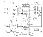
- FIG. 1 is a conceptual diagram showing an operating circuit for a circuit breaker according to Embodiment 1 of the present invention.
- an electromagnetic operating device 1 is provided with a coil for opening 1a that is disposed so as to surround an outer periphery of a movable element 2 connected to a movable contact such as a circuit breaker (not shown). , 1c and a closing coil 1b.
- An operation circuit 10 is provided to drive such an electromagnetic operating device 1, and this operating circuit 10 is connected to each coil 1a, 1b of the electromagnetic operating device 1 and supplies electrical energy necessary for the operation.
- These control units 3a and 4a are constituted by interlock circuits 6a and 7a for supplying drive signals.
- the control unit 3a supplies current to the opening coil 1a to drive the mover 2 to the opening side
- the control unit 4a supplies current to the closing coil 1b to cause the mover 2 to move. It is driven to the closing side.
- the capacitors 3 and 4 are charged with electrical energy necessary for opening and closing the electromagnetic operating device 1 via the control units 3a and 4a, and when the opening command 11a or the closing command 12a is input. If the interlock condition is satisfied, a command is input to the control units 3a and 4a via the interlock circuits 6a and 6b, and the electric energy charged in the capacitors 3 and 4 is transferred via the control units 3a and 4a. Thus, the opening coil 1a and the closing coil 1b are discharged to drive the electromagnetic operating device 1. Note that only one of the opening command 11a and the closing command 12a is input to the control unit 3a or the control unit 4a by the interlock circuits 6a and 7a. In addition, the control units 3a and 4a are integrated into an electronic board and configured as one control unit 10a. Further, as shown in FIG. 2, the opening capacitor and the closing capacitor can be constituted by a single capacitor 21.
- an opening coil 1c is added, and a capacitor 5 and a control unit 5a are added corresponding to the opening coil 1c
- the electromagnetic operating device 1 can be driven by either the opening coil 1a or the opening coil 1c.
- Examples of providing such two opening coils include winding the opening coil 1c on the same core over the opening coil 1a, or winding the opening coil 1a and the opening coil. It is conceivable that both 1c are arranged side by side in the axial direction of the mover 2 so as to surround the mover 2 in the electromagnetic operating device 1.
- the closing command 12a and the opening command 11b may be input simultaneously.
- the control unit 5a utilizes a contact signal that is turned on immediately after the command is input and turned off when the energization of the coil is completed. That is, the contact signal 13 is output from the input of the opening command 11b to the controller 5a until the energization of the opening coil 1c is completed, and this contact signal 13 is supplied to the interlock circuit 7a to the controller 4a. The closing command 12a is prevented from being supplied.
- the closing coil 1b When the closing coil 1b is energized, the contact signal 14 is output from the control unit 4a and supplied to the interlock circuit 6b. While the contact signal 14 is being input, the control unit 5a is opened. The supply of the polar command 11b is blocked. With this configuration, it is possible to prevent the closing command 12a and the opening command 11b from being supplied to the electromagnetic operating device 1 at the same time.
- the opening command 11a and the opening command 11b are overlapped, an electromagnetic force acts in the same direction, so that it is assumed that the influence on the configuration of the electromagnetic operating device may be small.
- the opening side device is configured as a duplex system
- the operation circuit can be further increased, and multiplexing can be performed by monitoring the output of the contact signal between a plurality of control units. .
- FIG. FIG. 3 is a conceptual diagram showing a circuit breaker operating circuit according to Embodiment 2 of the present invention.
- the present invention will be described below with reference to FIG. 3, the same reference numerals as those in FIG. 1 denote the same or corresponding components, and the description thereof is omitted.
- this Embodiment 2 the structure which arranges the control unit 10a manufactured by the same manufacturing apparatus and the control unit 10b in parallel is shown.
- the control side 5a and the control unit 9a should not be operated simultaneously.
- one closing command 12a is branched and inputted to the control units 4a and 9a of the operation circuit. At this time, it becomes necessary to connect the capacitor 9 and the closing coil to the closing-side control unit 9a, but it is necessary to functionally dispose the coil in duplicate with the closing coil 1b. Therefore, for example, a resistor 8 simulating a coil is connected and arranged separately from the electromagnetic operating device 1.
- the value of the resistor 8 is set to be larger than the closing coil 1b to such an extent that the operation is not hindered, the energization current is suppressed, and the shape related to the energization capacity of the circuit (the thickness of the electric wire, the width of the substrate pattern, etc.) ) Can be kept small. Furthermore, since the capacitor 9 does not need to be charged with energy necessary for electromagnetic operation on the closing coil, a capacitor having a small capacity that does not cause a problem with the charging function of the control unit 9a can be used.
- the contact signal 13 based on the operation state of the control unit 5a is output and supplied to the interlock circuit 7a. While the contact signal 13 is being input, supply of the closing command 12a to the control unit 4a is blocked.
- the configuration is the same as in the first embodiment.
- the control units 10a and 10b having the same specifications are used and the opening side operation circuit is duplicated, the capacitance of the operation circuit on the closing side that does not need to be duplicated, the resistance corresponding to the coil, etc. It is possible to apply alternatives to the above, and it is possible to reduce the specifications (function, performance, number, etc.) from the parts that are originally required to double the control unit, thus reducing costs. Can do. In addition, the number of production lots can be increased by manufacturing the control units 10a and 10b with the same manufacturing apparatus, and the cost per unit can be suppressed.
- control unit 10a and the control unit 10b are configured by electronic boards
- the control unit 3a and the control unit 4a or the control unit 5a and the control unit 9a sense each other's energization state and do not energize at the same time.
- Such control can be easily performed. Therefore, the energization state of the control unit 4a is the same as the energization state of the control unit 9a, and the control unit 5a and the control unit 9a can monitor the energization state inside one control unit 10b. 1 can be omitted, and wiring can be reduced.
- FIG. FIG. 4 is a conceptual diagram showing a circuit breaker operating circuit according to Embodiment 3 of the present invention.
- the present invention will be described below with reference to FIG. 4, the same reference numerals as those in FIGS. 1 and 3 denote the same or corresponding components, and the description thereof is omitted.
- the third embodiment a configuration in which the operation circuit to which the control unit 10a is connected is specialized for normal operation and the operation circuit to which the control unit 10b is connected is specialized for the purpose of emergency opening is shown.
- an alarm contact signal 15 indicating an abnormality is output from the control unit 10 a, and the contact signal 15 is supplied to the control unit 16.
- the control unit 16 Upon receiving the alarm contact signal 15 indicating an abnormality, the control unit 16 outputs a contact opening command, operates the control unit 5a via the interlock circuit 6b, and forcibly opens the contact.
- the control unit 16 by inputting the alarm contact signal 17 from the outside of the circuit breaker to the control unit 16 as well, there is an abnormality in either the substation or the entire building where the switchgear including the circuit breaker or the switchgear is introduced. When it occurs, the circuit breaker can be opened, and the reliability of power receiving equipment operation can be improved.
- an alarm contact other than the circuit breaker for example, when a gas-insulated switchgear is applied, it can be considered as a gas leak alarm contact, and also when the control power supply of a substation or switchgear is stopped
- An alarm contact an alarm contact indicating a state failure of a peripheral device to which the switch gear is connected may be considered.
- the circuit breaker has been described as an example.
- the switch that is a superordinate concept of the circuit breaker that is, the circuit breaker having the fault current interruption capability of the circuit, Even an electromagnetic contactor, a normal switch, etc. can be applied, and an equivalent effect can be obtained.
- each embodiment can be appropriately modified or omitted within the scope of the invention.
- Electromagnetic operation device 1a, 1c: opening coil, 1b: closing coil, 2: mover, 3, 5: opening capacitor, 4: closing capacitor, 3a, 4a, 5a, 9a : Control unit, 6a, 6b, 7a: interlock circuit, 8: resistor, 9: capacitor, 10: operation circuit, 10a, 10b: control unit, 11a, 11b: opening command, 12a: closing command, 13, 14, 15: contact signal, 16: control unit, 17: contact signal, 21: capacitor. *
Abstract
Description
さらに、コンデンサに充電したエネルギーを投入用あるいは遮断用のコイルに通電することにより励磁し、磁気吸引力により可動子を駆動する方式の電磁操作装置が知られている(例えば、特許文献3参照)。 In the conventional circuit breaker, there is a case where the opening side operation coil is doubled for the purpose of improving the reliability in the system, and the opening operation is more reliably performed. (For example, refer to
Further, there is known an electromagnetic operating device of a type in which energy charged in a capacitor is excited by energizing a turning-on or shut-off coil and a movable element is driven by a magnetic attractive force (see, for example, Patent Document 3). .
図1は、この発明の実施の形態1である遮断器の操作回路を示す概念図で、以下、図に基づいて、この発明を説明する。
図1において、電磁操作装置1は、遮断器(図示せず)などの可動接点に連結された可動子2に対し、この可動子2の外周を取り巻くように配設された開極用コイル1a,1cおよび閉極用コイル1bを備えて構成されている。このような電磁操作装置1を駆動させるため操作回路10が設けられており、この操作回路10は、電磁操作装置1の各コイル1a、1bに接続され、操作に必要な電気的エネルギーを供給して電磁力を発生するためのコンデンサ3、4と、コンデンサ3、4に対して充電動作または放電動作(コイルへの通電動作)の切り替えや通電を行うスイッチ機能を有する制御部3a、4aと、これらの制御部3a、4aに駆動信号を供給するインタロック回路6a,7aとから構成されている。ここで、制御部3aは、開極用コイル1aに電流を供給して可動子2を開極側に駆動し、制御部4aは、閉極用コイル1bに電流を供給して可動子2を閉極側に駆動するものである。
FIG. 1 is a conceptual diagram showing an operating circuit for a circuit breaker according to
In FIG. 1, an
なお、開極指令11aと閉極指令12aは、インタロック回路6a,7aによって、いずれか一方のみが制御部3aまたは制御部4aに入力されるように構成されている。また、制御部3a、4aは、電子基板に集約されて一つの制御ユニット10aとして構成されている。
さらに、図2に示すように開極用コンデンサと閉極用コンデンサを1つのコンデンサ21によって構成することも可能である。 The
Note that only one of the
Further, as shown in FIG. 2, the opening capacitor and the closing capacitor can be constituted by a
ここで、制御部5aに駆動信号を供給するインタロック回路6bにインタロック回路6a,7aと異なる独立した開極指令11bが入力されるように構成した場合、閉極指令12aと、開極指令11bとが同時に入力されることが考えられる。 In order to make the opening operation redundant with respect to the
Here, in a case where an
そこで、この発明では、制御部5aにおいて、指令入力後直ちにオンとなり、コイルへの通電が完了したときオフとなる接点信号を活用する。すなわち、制御部5aに開極指令11bが入力されてから開極用コイル1cの通電が完了するまで接点信号13が出力され、この接点信号13がインタロック回路7aに供給されて制御部4aへの閉極指令12aの供給を阻止するように構成している。 In this way, when the
Therefore, in the present invention, the
このように構成することによって、閉極指令12aと開極指令11bが同時に電磁操作装置1に供給されることを防ぐことができる。
なお、開極指令11aと開極指令11bが重複した場合には、同方向へ電磁力が働くため、電磁操作装置の構成にとって影響が小さくて済むことが想定される。 When the
With this configuration, it is possible to prevent the
When the
図3は、この発明の実施の形態2である遮断器の操作回路を示す概念図で、以下、図3に基づいて、この発明を説明する。
図3において、図1と同一符号は、同一または相当する構成を示しており、その説明を省略する。
この実施の形態2においては、同じ製造装置によって製造された制御ユニット10aと制御ユニット10bとを並設する構成を示している。
ここで、開極側操作回路のみを冗長化(二重化)し、閉極側操作回路を冗長化(二重化)する必要がない場合は、制御部5aおよび制御部9aが同時に動作しないよう閉極側操作回路の制御部4a、9aに一つの閉極指令12aを分岐して入力することが考えられる。このとき、閉極側の制御部9aに対して、コンデンサ9および閉極用コイルを接続する必要性が生じることになるが、機能上コイルを閉極用コイル1bと二重に配置する必要がないため、例えばコイルを模した抵抗8を接続し、電磁操作装置1と別に配置するように構成している。
FIG. 3 is a conceptual diagram showing a circuit breaker operating circuit according to
3, the same reference numerals as those in FIG. 1 denote the same or corresponding components, and the description thereof is omitted.
In this
Here, when it is not necessary to make only the opening side operation circuit redundant (duplex) and make the closing side operation circuit redundant (duplication), the
なお、制御部5aの動作状態に基づく接点信号13を出力してインタロック回路7aに供給し、接点信号13が入力されている間は、制御部4aへの閉極指令12aの供給を阻止するように構成している点は、実施の形態1と同じである。 Here, if the value of the
The
また、制御ユニット10a、10bを同じ製造装置によって製造することによって製作ロット数を増やし、1ユニット当たりのコストを抑制することも可能となる。 As described above, when the
In addition, the number of production lots can be increased by manufacturing the
図4は、この発明の実施の形態3である遮断器の操作回路を示す概念図で、以下、図4に基づいて、この発明を説明する。
図4において、図1および図3と同一符号は、同一または相当する構成を示しており、その説明を省略する。
この実施の形態3においては、制御ユニット10aが接続された操作回路を通常操作用、制御ユニット10bが接続された操作回路を非常開極用という目的に特化した場合の構成を示している。
FIG. 4 is a conceptual diagram showing a circuit breaker operating circuit according to
4, the same reference numerals as those in FIGS. 1 and 3 denote the same or corresponding components, and the description thereof is omitted.
In the third embodiment, a configuration in which the operation circuit to which the
このような回路構成にすることによって、通常操作用の操作回路で異常が発生した時に、外部からの開極指令11bを待つことなく、直ちに制御部16から開極操作するシステムが構築できるため、異常に伴う遮断器の誤動作を防止することができ、遮断器の運用における信頼性を向上させることができる。 That is, in the operation circuit for normal operation including the
By adopting such a circuit configuration, when an abnormality occurs in the operation circuit for normal operation, it is possible to construct a system that can immediately perform the opening operation from the
さらに、上述の実施の形態1~実施の形態3においては、遮断器を例に説明したが、遮断器の上位概念である開閉器、すなわち、電路の事故電流遮断能力を持つ遮断器の他、電磁接触器、通常のスイッチなどであっても適用することができ、同等の効果を得ることができる。
なお、本発明は、その発明の範囲内において、各実施の形態を適宜、変形、省略することが可能である。 In addition, as an alarm contact other than the circuit breaker, for example, when a gas-insulated switchgear is applied, it can be considered as a gas leak alarm contact, and also when the control power supply of a substation or switchgear is stopped An alarm contact, an alarm contact indicating a state failure of a peripheral device to which the switch gear is connected may be considered.
Furthermore, in the above-described first to third embodiments, the circuit breaker has been described as an example. However, in addition to the switch that is a superordinate concept of the circuit breaker, that is, the circuit breaker having the fault current interruption capability of the circuit, Even an electromagnetic contactor, a normal switch, etc. can be applied, and an equivalent effect can be obtained.
In the present invention, each embodiment can be appropriately modified or omitted within the scope of the invention.
Claims (7)
- 電磁操作装置内において可動子を開閉器の閉極側に駆動する閉極用コイルと、前記閉極用コイルに電気的エネルギーを供給する閉極用コンデンサと、前記閉極用コイルおよび前記閉極用コンデンサの間に接続され、前記閉極用コンデンサへの充電と前記閉極用コイルへの通電の制御を行う閉極用制御部と、前記電磁操作装置内において前記可動子を開閉器の開極側に駆動する開極用コイルと、前記開極用コイルに電気的エネルギーを供給する開極用コンデンサと、前記開極用コイルおよび前記開極用コンデンサの間に接続され、前記開極用コンデンサへの充電と前記開極用コイルへの通電の制御を行う開極用制御部と、前記閉極用制御部または前記開極用制御部に通電する第1のインタロック回路と、前記電磁操作装置内において前記可動子を開閉器の開極側に駆動する第2の開極用コイルと、前記第2の開極用コイルに電気的エネルギーを供給する第2の開極用コンデンサと、前記第2の開極用コイルおよび前記第2の開極用コンデンサの間に接続され、前記第2の開極用コンデンサへの充電と前記第2の開極用コイルへの通電の制御を行う第2の開極用制御部と、前記第2の開極用制御部に通電する第2のインタロック回路とを備え、
前記第2の開極用制御部が動作中であることを示す信号に基づいて前記閉極用制御部の動作を阻止するように構成したことを特徴とする開閉器。 A closing coil that drives the mover to the closing side of the switch in the electromagnetic operating device, a closing capacitor that supplies electrical energy to the closing coil, the closing coil, and the closing electrode A closing control unit that is connected between the capacitors for controlling charging of the closing capacitor and energizing the closing coil; and opening the switch in the electromagnetic operating device. An opening coil that is driven to the pole side, an opening capacitor that supplies electrical energy to the opening coil, and is connected between the opening coil and the opening capacitor; An opening controller that controls charging of the capacitor and energization of the opening coil; a first interlock circuit that energizes the closing controller or the opening controller; and the electromagnetic The mover in the operating device A second opening coil for driving to the opening side of the switch; a second opening capacitor for supplying electrical energy to the second opening coil; and the second opening coil. And a second opening controller that is connected between the second opening capacitor and controls charging of the second opening capacitor and energization of the second opening coil. And a second interlock circuit for energizing the second opening control unit,
A switch configured to block the operation of the closing control unit based on a signal indicating that the second opening control unit is operating. - 前記閉極用制御部が動作中であることを示す信号に基づいて前記第2の開極用制御部の動作を阻止するように構成したことを特徴とする請求項1に記載の開閉器。 2. The switch according to claim 1, wherein the switch is configured to block the operation of the second opening control unit based on a signal indicating that the closing control unit is operating.
- 複数の前記開極用コイルを、前記可動子に対する同一位置で重なるように巻き付けたことを特徴とする請求項1に記載の開閉器。 The switch according to claim 1, wherein a plurality of the opening coils are wound so as to overlap at the same position with respect to the mover.
- 複数の前記開極用コイルを、前記可動子に対し並べて配置したことを特徴とする請求項1に記載の開閉器。 The switch according to claim 1, wherein a plurality of the opening coils are arranged side by side with respect to the mover.
- 前記開極用制御部と前記閉極用制御部を、1つの制御ユニットとして構成したことを特徴とする請求項1から請求項4のいずれか一項に記載の開閉器。 The switch according to any one of claims 1 to 4, wherein the opening control unit and the closing control unit are configured as one control unit.
- 前記開極用制御部と前記閉極用制御部とからなる制御ユニットを2個設け、前記第2の開極用制御部を含む制御ユニットにおける第2の閉極用制御部にコイルに代えて抵抗を接続したことを特徴とする請求項5に記載の開閉器。 Two control units comprising the opening control unit and the closing control unit are provided, and the second closing control unit in the control unit including the second opening control unit is replaced with a coil. The switch according to claim 5, wherein a resistor is connected.
- 前記制御ユニットの異常に伴う接点信号を前記第2のインタロック回路に供給するように構成したことを特徴とする請求項5に記載の開閉器。 The switch according to claim 5, wherein a contact signal associated with an abnormality of the control unit is supplied to the second interlock circuit. *
Priority Applications (4)
| Application Number | Priority Date | Filing Date | Title |
|---|---|---|---|
| EP15842495.2A EP3196912B1 (en) | 2014-09-18 | 2015-03-06 | Switch |
| JP2015532217A JP5868558B1 (en) | 2014-09-18 | 2015-03-06 | Switch |
| US15/317,150 US10510473B2 (en) | 2014-09-18 | 2015-03-06 | Switchgear |
| CN201580035516.2A CN106663563B (en) | 2014-09-18 | 2015-03-06 | Derailing switch |
Applications Claiming Priority (2)
| Application Number | Priority Date | Filing Date | Title |
|---|---|---|---|
| JP2014190186 | 2014-09-18 | ||
| JP2014-190186 | 2014-09-18 |
Publications (1)
| Publication Number | Publication Date |
|---|---|
| WO2016042803A1 true WO2016042803A1 (en) | 2016-03-24 |
Family
ID=55532852
Family Applications (1)
| Application Number | Title | Priority Date | Filing Date |
|---|---|---|---|
| PCT/JP2015/056656 WO2016042803A1 (en) | 2014-09-18 | 2015-03-06 | Switch |
Country Status (4)
| Country | Link |
|---|---|
| US (1) | US10510473B2 (en) |
| EP (1) | EP3196912B1 (en) |
| CN (1) | CN106663563B (en) |
| WO (1) | WO2016042803A1 (en) |
Cited By (1)
| Publication number | Priority date | Publication date | Assignee | Title |
|---|---|---|---|---|
| EP3376519A1 (en) * | 2017-03-13 | 2018-09-19 | ABB Schweiz AG | A switching device for medium voltage electric power distribution installations |
Families Citing this family (2)
| Publication number | Priority date | Publication date | Assignee | Title |
|---|---|---|---|---|
| CN106663563B (en) * | 2014-09-18 | 2019-05-28 | 三菱电机株式会社 | Derailing switch |
| EP3460822B1 (en) * | 2017-09-26 | 2021-04-07 | ABB Schweiz AG | Method for operating a medium voltage circuit breaker or recloser and medium voltage circuit breaker or recloser itself |
Citations (4)
| Publication number | Priority date | Publication date | Assignee | Title |
|---|---|---|---|---|
| JPS59101729A (en) * | 1982-12-03 | 1984-06-12 | 東芝エンジニアリング株式会社 | Control circuit for breaker |
| JP2007157830A (en) * | 2005-12-01 | 2007-06-21 | Toyota Motor Corp | Controller of electromagnetic valve |
| JP2008053387A (en) * | 2006-08-23 | 2008-03-06 | Nissin Electric Co Ltd | Solenoid controller |
| JP2010272296A (en) * | 2009-05-20 | 2010-12-02 | Mitsubishi Electric Corp | State recognition unit for switching device or electromagnetic operation device |
Family Cites Families (14)
| Publication number | Priority date | Publication date | Assignee | Title |
|---|---|---|---|---|
| JPH04111237U (en) | 1991-03-12 | 1992-09-28 | 富士電機株式会社 | Double trip circuit for power circuit breakers |
| JP3816284B2 (en) * | 1998-12-28 | 2006-08-30 | 三菱電機株式会社 | Switchgear |
| FR2793944B1 (en) * | 1999-05-20 | 2001-07-13 | Schneider Electric Ind Sa | OPENING AND / OR CLOSING CONTROL DEVICE, PARTICULARLY FOR A BREAKING APPARATUS SUCH AS A CIRCUIT BREAKER, AND CIRCUIT BREAKER PROVIDED WITH SUCH A DEVICE |
| JP2002124158A (en) * | 2000-10-16 | 2002-04-26 | Mitsubishi Electric Corp | Switch device |
| JP4758339B2 (en) * | 2004-05-13 | 2011-08-24 | 三菱電機株式会社 | Status grasp method |
| US7280338B2 (en) * | 2005-05-12 | 2007-10-09 | Eaton Corporation | Power supply circuit, back-pack power supply module and circuit interrupter including the same |
| JP4535193B2 (en) * | 2006-03-17 | 2010-09-01 | 三菱電機株式会社 | State grasping device and opening / closing control device provided with the state grasping device |
| JP4833739B2 (en) | 2006-06-01 | 2011-12-07 | 株式会社日立製作所 | Breaker |
| US8040210B2 (en) * | 2006-09-28 | 2011-10-18 | Mitsubishi Electric Corporation | Electromagnetically operated switching device |
| CN102834888B (en) * | 2010-04-02 | 2015-02-18 | 三菱电机株式会社 | Drive circuit for electromagnetic manipulation mechanism |
| JP5606304B2 (en) | 2010-12-17 | 2014-10-15 | 三菱電機株式会社 | Electromagnetic operation device and drive circuit for switchgear |
| DE112011105570B4 (en) * | 2011-08-29 | 2020-01-30 | Mitsubishi Electric Corp. | Electromagnetic actuator for vacuum circuit breakers |
| JP5734529B2 (en) * | 2013-03-13 | 2015-06-17 | 三菱電機株式会社 | Electromagnetic operation device |
| CN106663563B (en) * | 2014-09-18 | 2019-05-28 | 三菱电机株式会社 | Derailing switch |
-
2015
- 2015-03-06 CN CN201580035516.2A patent/CN106663563B/en active Active
- 2015-03-06 EP EP15842495.2A patent/EP3196912B1/en active Active
- 2015-03-06 WO PCT/JP2015/056656 patent/WO2016042803A1/en active Application Filing
- 2015-03-06 US US15/317,150 patent/US10510473B2/en active Active
Patent Citations (4)
| Publication number | Priority date | Publication date | Assignee | Title |
|---|---|---|---|---|
| JPS59101729A (en) * | 1982-12-03 | 1984-06-12 | 東芝エンジニアリング株式会社 | Control circuit for breaker |
| JP2007157830A (en) * | 2005-12-01 | 2007-06-21 | Toyota Motor Corp | Controller of electromagnetic valve |
| JP2008053387A (en) * | 2006-08-23 | 2008-03-06 | Nissin Electric Co Ltd | Solenoid controller |
| JP2010272296A (en) * | 2009-05-20 | 2010-12-02 | Mitsubishi Electric Corp | State recognition unit for switching device or electromagnetic operation device |
Non-Patent Citations (1)
| Title |
|---|
| See also references of EP3196912A4 * |
Cited By (4)
| Publication number | Priority date | Publication date | Assignee | Title |
|---|---|---|---|---|
| EP3376519A1 (en) * | 2017-03-13 | 2018-09-19 | ABB Schweiz AG | A switching device for medium voltage electric power distribution installations |
| CN108573828A (en) * | 2017-03-13 | 2018-09-25 | Abb瑞士股份有限公司 | Switchgear for medium-voltage distribution appts |
| US10707041B2 (en) | 2017-03-13 | 2020-07-07 | Abb Schweiz Ag | Switching device for medium voltage electric power distribution installations |
| CN108573828B (en) * | 2017-03-13 | 2022-04-12 | Abb瑞士股份有限公司 | Switching device for medium-voltage switchgear assemblies |
Also Published As
| Publication number | Publication date |
|---|---|
| EP3196912A4 (en) | 2018-05-02 |
| CN106663563B (en) | 2019-05-28 |
| EP3196912A1 (en) | 2017-07-26 |
| EP3196912B1 (en) | 2019-05-08 |
| US20170125182A1 (en) | 2017-05-04 |
| CN106663563A (en) | 2017-05-10 |
| US10510473B2 (en) | 2019-12-17 |
Similar Documents
| Publication | Publication Date | Title |
|---|---|---|
| JP5059197B2 (en) | Selection switch device, power supply device using the same, and switching method thereof | |
| JP2003528495A (en) | Safety switching device and safety switching device system | |
| US9219384B2 (en) | Modular power skid that can meet two or more different datacenter tier ratings | |
| EP2592502B1 (en) | Safety control system | |
| WO2016042803A1 (en) | Switch | |
| JP5615470B1 (en) | Power supply control device and programmable logic controller | |
| JP5868558B1 (en) | Switch | |
| US9969341B2 (en) | Assistance device and method for a power generation system of an aircraft | |
| WO2008027867A2 (en) | An on-line testable solid state reversing dc motor starter | |
| JP5275147B2 (en) | Operation method of commutation type DC circuit breaker | |
| JP6676226B1 (en) | Electromagnetic operating device | |
| JP6401686B2 (en) | Inverter device for motor drive | |
| KR101398409B1 (en) | Control apparatus, power supply system, method and computer program product | |
| JP6450508B2 (en) | Drive device for hysteresis motor | |
| JP2009118642A (en) | Protection relay system | |
| EP2885866B1 (en) | Improved diagnostics for multi-level medium voltage drive using mechanical bypass | |
| CN103871788B (en) | Electric switching system | |
| CN110380505B (en) | Elevator emergency control system and emergency control method thereof | |
| CN114157182A (en) | Control interface for medium voltage circuit breakers and switches | |
| JP2024037163A (en) | Relay device and safety switch device with at least one relay device | |
| WO2016007164A1 (en) | Apparatus and method for control of switching circuitry | |
| JP2021096494A (en) | Safety signal output device, mounting member, safety system and monitoring nullification method | |
| JP2015056138A (en) | Emergency lighting apparatus control device | |
| KR20160113877A (en) | Digital output terminal unit for turbine generator control system |
Legal Events
| Date | Code | Title | Description |
|---|---|---|---|
| ENP | Entry into the national phase |
Ref document number: 2015532217 Country of ref document: JP Kind code of ref document: A |
|
| 121 | Ep: the epo has been informed by wipo that ep was designated in this application |
Ref document number: 15842495 Country of ref document: EP Kind code of ref document: A1 |
|
| WWE | Wipo information: entry into national phase |
Ref document number: 15317150 Country of ref document: US |
|
| REEP | Request for entry into the european phase |
Ref document number: 2015842495 Country of ref document: EP |
|
| WWE | Wipo information: entry into national phase |
Ref document number: 2015842495 Country of ref document: EP |
|
| NENP | Non-entry into the national phase |
Ref country code: DE |