WO2016042596A1 - Structure de raccord de tuyaux métalliques et procédé de raccordement - Google Patents
Structure de raccord de tuyaux métalliques et procédé de raccordement Download PDFInfo
- Publication number
- WO2016042596A1 WO2016042596A1 PCT/JP2014/074376 JP2014074376W WO2016042596A1 WO 2016042596 A1 WO2016042596 A1 WO 2016042596A1 JP 2014074376 W JP2014074376 W JP 2014074376W WO 2016042596 A1 WO2016042596 A1 WO 2016042596A1
- Authority
- WO
- WIPO (PCT)
- Prior art keywords
- tube
- metal tube
- metal
- pipe
- diameter
- Prior art date
Links
Images


Classifications
-
- F—MECHANICAL ENGINEERING; LIGHTING; HEATING; WEAPONS; BLASTING
- F16—ENGINEERING ELEMENTS AND UNITS; GENERAL MEASURES FOR PRODUCING AND MAINTAINING EFFECTIVE FUNCTIONING OF MACHINES OR INSTALLATIONS; THERMAL INSULATION IN GENERAL
- F16L—PIPES; JOINTS OR FITTINGS FOR PIPES; SUPPORTS FOR PIPES, CABLES OR PROTECTIVE TUBING; MEANS FOR THERMAL INSULATION IN GENERAL
- F16L13/00—Non-disconnectible pipe-joints, e.g. soldered, adhesive or caulked joints
- F16L13/14—Non-disconnectible pipe-joints, e.g. soldered, adhesive or caulked joints made by plastically deforming the material of the pipe, e.g. by flanging, rolling
Definitions
- the present invention relates to a joint structure between metal pipes used for housing equipment and building members, and a joint method thereof.
- various metal pipes are used for housing equipment, building members, automobile-related parts, and the like. When long metal pipes are required, the metal pipes are often joined together.
- a welding joint at the pipe end a brazing joint, a joining method using a flange joint, or a joining method such as a quick fastener is employed.
- Patent Document 1 a method of screwing a metal tube having a female screw at the tube end and a metal tube having a male screw at the tube end is also employed.
- the flange joint takes time to form the flange portion in advance at the pipe end, and when fixing the flange portion by bringing the flange portions into contact with each other, auxiliary materials such as bolts and nuts are required. As a result, the cost becomes high. Also for joining via a joining member such as a quick fastener, a secondary material having a uniform shape is required, resulting in high costs.
- the present invention has been devised to solve such problems, and when connecting the pipe ends of metal pipes, it is possible to easily connect them without using auxiliary materials or joining members. And it aims at providing the joint structure which can exhibit predetermined pressure resistance even if it is a joined body of dissimilar metal pipes.
- the metal pipe joint structure of the present invention forms a fitting portion by inserting an end portion of another metal tube into an end portion of one metal tube,
- a metal tube joint structure is characterized in that a force is applied to the fitting portion from the outside so that the fitting portion is crimped.
- the joint structure according to the present invention further applies the external force to the fitting portion in which the inner metal tube is inserted into the outer metal tube, whereby the outer metal tube in the fitting portion is applied.
- An uneven portion is formed in the inner metal tube.
- grooved part has the cross-sectional shape fitted.
- the above-mentioned external force indicates that the uneven portion is formed by machining, and the machining is preferably a rolling process.
- the joint method according to the present invention includes a first sleeve having an inner diameter equal to or greater than an outer diameter of a metal pipe to be joined, when joining one metal pipe having substantially the same diameter and another metal pipe.
- a second sleeve having an outer diameter equal to or less than the inner diameter of the metal pipe to be joined is used as an auxiliary, and the end of the one metal pipe and the end of the other metal pipe are joined to the first sleeve.
- An uneven portion is provided by rolling the joint portion.
- grooved part has the cross-sectional shape fitted.
- joint structure of the present invention it is possible to join metal pipes without using auxiliary materials or joining members. Further, since the inner metal tube and the outer metal tube of the fitting portion subjected to the rolling process are in close contact with each other, it is possible to prevent the fluid from leaking even when the fluid flows in the tube. .
- the joining strength can be improved by changing the number of concavo-convex parts, groove shape, groove depth, or groove pitch when rolling.
- the convex and concave portions are formed from the outer metal tube through the inner metal tube has been described.
- the concavo-convex portion is formed only in the outer metal tube, and the inner metal tube is a base tube. Even if it is a shape, the frictional force due to the crimping of both pipes is improved, and it becomes possible to perform bonding that exhibits excellent pressure resistance and tensile properties.
- two metal tubes are prepared. These metal tubes may have different diameters, but it is more preferable that they have the same diameter assuming the use of the metal tube after joining.
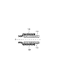
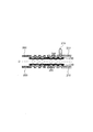
- the end portion of the outer metal tube is expanded (see FIG. 1A).
- the end of the inner metal tube may be reduced in diameter.
- the tube end of the inner metal tube 110 is inserted into the tube end of the outer metal tube 100 (see FIG. 1B). After that, the fitting portion in which the tube end of the inner metal tube 110 is inserted into the tube end of the outer metal tube 100 is machined from the outer peripheral surface side toward the inner side of the metal tube to form an uneven portion.
- the joint structure of the invention can be constructed.
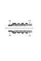
- the metal tube can be grooved by rounding the tip of the roll to be used.
- the concavo-convex portion in the fitting portion of the metal tube not only the inner peripheral surface of the outer metal tube 100 is pressure-bonded to the outer peripheral surface of the inner metal tube 110 but also the concavo-convex portion of the outer metal tube 100 is the inner metal tube. 110, and the convex portions formed on the inner peripheral surface of the outer metal tube 100 are in close contact with the concave portions formed on the outer peripheral surface of the inner metal tube 110, so that both metal tubes are firmly fitted in the concave and convex portions. (See FIG. 1D).
- the fitting portion of the metal tubes has a sealing effect. Therefore, even in a usage mode in which a fluid is arranged inside the metal tube, there is little possibility that the fluid inside leaks out.
- FIG. 1E shows a method for fitting a metal tube according to the present invention, wherein the end of the metal tube to be the inner metal tube is subjected to diameter reduction processing and then inserted into the end of the outer metal tube to form a fitting portion. Then, it is a joint structure formed by subjecting the fitting portion to machining from the outer peripheral surface side toward the inside of the metal tube to form an uneven portion.
- metal tube used in the present invention.
- a steel pipe may be sufficient and a copper pipe and an aluminum pipe may be sufficient.
- the metal pipes to be joined may be the same type of metal pipes or may be metal pipes of different types.
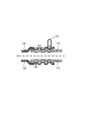
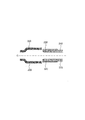
- auxiliary sleeve 220 in FIG. 2A a short cylindrical tube having an inner diameter equal to or greater than the outer diameter of the metal tube to be connected is prepared.
- the pipe ends of the metal pipes 200 and 210 to be connected are inserted into both ends of the auxiliary sleeve 220 (see FIG. 2A).
- auxiliary sleeve 220 is machined from the outer peripheral surface side of the auxiliary sleeve 220 into which the metal pipes 200 and 210 to be connected are inserted to the inside of the metal pipe to form an uneven portion (see FIG. 2B).
- Metal pipes can be joined to each other via
- auxiliary sleeve is arranged inside the metal pipes 200 and 210 to be connected.
- a short cylindrical tube (see the auxiliary sleeve 230 in FIG. 2C) having an outer diameter equal to or smaller than the inner diameter of the metal tube to be connected is prepared.
- the pipe ends of the metal pipes 200 and 210 to be connected are inserted so as to cover both ends of the auxiliary sleeve 230 (see FIG. 2C).
- the auxiliary sleeve Metal pipes can be joined to each other via
- auxiliary sleeve By using the auxiliary sleeve as described above, prior processing such as expansion of the outer metal tube or diameter reduction of the inner metal tube is unnecessary, and the metal tubes can be easily connected at the construction site.
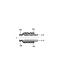
- the R-attached roll 330 having a rounded tip is rotated around the pipe of the metal tube, and at the same time, the outer diameter of the roll is reduced to reduce the revolution diameter of the roll, thereby forming an uneven portion (see FIG. See 3C).
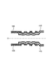
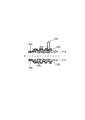
- FIGS. 4A to 4C a method for forming the uneven portion in the joint portion using the O-ring will be described with reference to FIGS. 4A to 4C.
- two metal tubes are prepared, and tube expansion processing is performed on the end portion of the outer metal tube (outer metal tube 400) (see FIG. 4A).
- a single groove having a diameter ⁇ 12.0 mm at the groove bottom and a depth of 0.35 mm is formed on the outer peripheral surface of the inner metal tube 410 so as to meet the inner diameter reference value of the O-ring at a position 7 mm from the tube end.
- An O-ring 420 was fitted into the groove (see FIG. 4A).
- a rolling process or other methods can be employed.
- the inner metal tube 410 fitted with the O-ring 420 is inserted into the expanded portion of the outer metal tube 400 (see FIG. 4B), and at the same time the R-attached roll 430 with a rounded tip is rotated around the tube of the metal tube. By rolling the revolution diameter of the roll, the outer metal pipe 400 is rolled for joining (see FIG. 4C).
- the material includes a ⁇ 12.7 ⁇ 0.6t copper tube (JIS C 1220 phosphorous deoxidized copper O material, Hv50) and a ⁇ 12.7 ⁇ 0.4t ferritic stainless steel tube (22Cr-0.2Ti-0. 2Nb-1Mo, Hv170) was used to join a copper tube and a stainless steel tube.
- the anti-corrosion sealant Hermeseal 55 manufactured by Nippon Helmetics Co., Ltd. or a nitrile rubber O-ring manufactured by Akitsu Industry Co., Ltd. was used for sealing the gap between the pipes.
- An uneven portion was formed by machining (see FIG. 1C). The number of grooves was three, the groove pitch was 7 mm, and the groove depth was varied from 0 to 1.2 mm.
- the number of grooves was 3, the groove pitch was 7 mm, and the groove depth was changed from 0 to 1.2 mm.
- the outer metal pipe was rolled for joining (see FIG. 4C).
- the number of grooves was one, the position of the grooves was 10 mm from the tube end arranged outside, and the depth of the grooves was 1.0 mm.
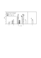
- Evaluation 1 The joint strength was evaluated as an evaluation test of each prototype joint.
- the test method is as follows. The end of each of the outer metal tube and the inner metal tube was gripped by a hydraulic chuck with a universal testing machine, pulled at a speed of 10 mm / min, and the maximum load until disconnection or breakage was measured. In order to prevent deformation of the tube end portion of the raw tube due to chucking, an inner die of ⁇ 11.5 ⁇ L50 was inserted only into the portion restrained by the hydraulic chuck. The tensile strength of the stainless steel pipe is 8.2 kN, and the tensile strength of the copper pipe is 4.9 kN.
- FIG. 5 summarizes the results for the following seven test specimens.
- A The type of Production Example 3 in which the outer metal tube is a stainless steel tube, the inner metal tube is a copper tube, and a sealing agent is used in combination.
- B The outer metal tube is a stainless steel tube, the inner metal tube is a copper tube, and no sealant is used together (non-seal).
- the outer metal tube is a copper tube
- the inner metal tube is a stainless steel tube
- the sealant is not used together (non-seal).
- D In connecting the stainless steel pipe and the copper pipe of the same diameter, the type of Production Example 2 using an auxiliary sleeve outside the metal pipe
- E When connecting a stainless steel pipe and a copper pipe of the same diameter, a type (f) stainless steel pipe with an auxiliary sleeve inside the metal pipe is used, and the stainless steel pipe is placed outside and the copper pipe is placed inside.
- the inner tube is a copper tube and an O-ring is fitted into this to form an uneven portion (f), and the inner tube is a stainless steel tube and an O-ring is inserted into it to form an uneven portion (g) It was found that the former has higher bonding strength (see (f) and (g) in FIG. 5).
- Evaluation 2 The pressure resistance was evaluated as an evaluation test for each prototype joint.
- the test method is as follows. The tube end of one metal tube is sealed, and pressure is applied from the tube end of the other metal tube with a hydraulic pump. When there was no breakage or water leakage after 1 minute from pressurization, the maximum pressure resistance was measured by increasing the pressure by 1 MPa.
- the pressure resistance of the single copper pipe is 20 MPa, and the pressure resistance of the single stainless steel pipe is 45 MPa.
- Production Example 1 a type that does not use a sealing agent
- Production Example 3 a type that uses a sealing agent together
- Production Example 2 a type that uses an auxiliary sleeve
- the groove depth is made common.
- Production Example 4 O-ring type
- a single groove having a diameter ⁇ 12.0 mm at the groove bottom and a depth of 0.35 mm is formed so as to meet the inner diameter reference value of the O-ring. Fitted.
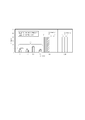
- the results of pressure resistance will be described with reference to FIG.
- the depth (unit: mm) of the groove of the concavo-convex portion is indicated by X, and the pressure resistance (unit: MPa) is indicated by Y.
- the outer metal tube is a stainless steel tube and a sealing agent is used (h).
- the outer metal tube is a stainless steel tube, and no sealing agent is used in combination (i).
- the results for the type (l) in which the uneven portion was formed and the type (m) in which the inner tube was a stainless steel pipe and the O-ring was fitted to form the uneven portion were summarized.
- the groove depth (X) is 0.35 mm.
- the pressure was increased to about 20 MPa, the copper tube broke (see (3) in FIG. 6).
Landscapes
- Engineering & Computer Science (AREA)
- General Engineering & Computer Science (AREA)
- Mechanical Engineering (AREA)
- Non-Disconnectible Joints And Screw-Threaded Joints (AREA)
Abstract
L'invention porte sur une structure de raccord, qui est apte à relier ensemble de façon simple les extrémités de tuyau de tuyaux métalliques sans l'utilisation de matériaux auxiliaires ou d'éléments de liaison, et qui est apte à réduire le temps de travail et le coût de travail. La structure de raccord selon la présente invention est caractérisée en ce qu'elle est une structure dans laquelle une section d'accouplement est formée par l'introduction, dans une section d'extrémité de l'un des tuyaux métalliques, de la section d'extrémité de l'autre tuyau métallique, et une force externe est appliquée à la section d'accouplement de façon à sertir la section d'accouplement. Par l'application de la force externe à la section d'accouplement avec le tuyau métallique interne introduit dans le tuyau métallique externe, des sections en bosse sont formées dans le tuyau métallique externe et le tuyau métallique interne au niveau de la section d'accouplement.
Priority Applications (1)
| Application Number | Priority Date | Filing Date | Title |
|---|---|---|---|
| PCT/JP2014/074376 WO2016042596A1 (fr) | 2014-09-16 | 2014-09-16 | Structure de raccord de tuyaux métalliques et procédé de raccordement |
Applications Claiming Priority (1)
| Application Number | Priority Date | Filing Date | Title |
|---|---|---|---|
| PCT/JP2014/074376 WO2016042596A1 (fr) | 2014-09-16 | 2014-09-16 | Structure de raccord de tuyaux métalliques et procédé de raccordement |
Publications (1)
| Publication Number | Publication Date |
|---|---|
| WO2016042596A1 true WO2016042596A1 (fr) | 2016-03-24 |
Family
ID=55532667
Family Applications (1)
| Application Number | Title | Priority Date | Filing Date |
|---|---|---|---|
| PCT/JP2014/074376 WO2016042596A1 (fr) | 2014-09-16 | 2014-09-16 | Structure de raccord de tuyaux métalliques et procédé de raccordement |
Country Status (1)
| Country | Link |
|---|---|
| WO (1) | WO2016042596A1 (fr) |
Cited By (2)
| Publication number | Priority date | Publication date | Assignee | Title |
|---|---|---|---|---|
| JP2020066033A (ja) * | 2018-10-25 | 2020-04-30 | 株式会社神戸製鋼所 | 異材接合方法、異材接合継手、異材接合用補助部材付き管状部材及びその製造方法 |
| EP4306839A1 (fr) * | 2022-07-15 | 2024-01-17 | Logstor Denmark Holding ApS | Capuchon d'extrémité pour un tuyau moyen d'un tuyau composite |
Citations (8)
| Publication number | Priority date | Publication date | Assignee | Title |
|---|---|---|---|---|
| US3071993A (en) * | 1959-07-08 | 1963-01-08 | Foster James Alfred | Tube joints and means and method of making the same |
| JPS4997918A (fr) * | 1973-01-24 | 1974-09-17 | ||
| JPS59226788A (ja) * | 1983-06-03 | 1984-12-19 | 日本金属工業株式会社 | ステンレス鋼管用継手 |
| EP0134566A2 (fr) * | 1983-08-29 | 1985-03-20 | Norsk Hydro A/S | Méthode de jonction permanente pour éléments tubulaires |
| JPS60143984U (ja) * | 1984-03-06 | 1985-09-24 | 日立金属株式会社 | 管継手接続構造 |
| JPH09257164A (ja) * | 1996-03-21 | 1997-09-30 | Calsonic Corp | 管体の接続構造 |
| JP2013066911A (ja) * | 2011-09-22 | 2013-04-18 | Nisshin Steel Co Ltd | 銅管とステンレス鋼管の接続体及びその製造方法 |
| JP2014181733A (ja) * | 2013-03-18 | 2014-09-29 | Nisshin Steel Co Ltd | 金属管の継手構造及び継手方法 |
-
2014
- 2014-09-16 WO PCT/JP2014/074376 patent/WO2016042596A1/fr active Application Filing
Patent Citations (8)
| Publication number | Priority date | Publication date | Assignee | Title |
|---|---|---|---|---|
| US3071993A (en) * | 1959-07-08 | 1963-01-08 | Foster James Alfred | Tube joints and means and method of making the same |
| JPS4997918A (fr) * | 1973-01-24 | 1974-09-17 | ||
| JPS59226788A (ja) * | 1983-06-03 | 1984-12-19 | 日本金属工業株式会社 | ステンレス鋼管用継手 |
| EP0134566A2 (fr) * | 1983-08-29 | 1985-03-20 | Norsk Hydro A/S | Méthode de jonction permanente pour éléments tubulaires |
| JPS60143984U (ja) * | 1984-03-06 | 1985-09-24 | 日立金属株式会社 | 管継手接続構造 |
| JPH09257164A (ja) * | 1996-03-21 | 1997-09-30 | Calsonic Corp | 管体の接続構造 |
| JP2013066911A (ja) * | 2011-09-22 | 2013-04-18 | Nisshin Steel Co Ltd | 銅管とステンレス鋼管の接続体及びその製造方法 |
| JP2014181733A (ja) * | 2013-03-18 | 2014-09-29 | Nisshin Steel Co Ltd | 金属管の継手構造及び継手方法 |
Cited By (3)
| Publication number | Priority date | Publication date | Assignee | Title |
|---|---|---|---|---|
| JP2020066033A (ja) * | 2018-10-25 | 2020-04-30 | 株式会社神戸製鋼所 | 異材接合方法、異材接合継手、異材接合用補助部材付き管状部材及びその製造方法 |
| JP7078515B2 (ja) | 2018-10-25 | 2022-05-31 | 株式会社神戸製鋼所 | 異材接合方法、異材接合継手、異材接合用補助部材付き管状部材及びその製造方法 |
| EP4306839A1 (fr) * | 2022-07-15 | 2024-01-17 | Logstor Denmark Holding ApS | Capuchon d'extrémité pour un tuyau moyen d'un tuyau composite |
Similar Documents
| Publication | Publication Date | Title |
|---|---|---|
| AU2012362443B2 (en) | Refrigeration line set fitting and method of using the same to join refrigeration lines to each other | |
| US3675949A (en) | Coupling fitting for connecting two pipes | |
| US3572779A (en) | Coupling fitting for connecting two parts | |
| US7987690B2 (en) | Fluid conduits with integral end fittings and associated methods of manufacture and use | |
| US20130119655A1 (en) | Coupling and joint for fixedly and sealingly securing components to one another | |
| JP5895330B2 (ja) | 高圧パイプ用継手のシーリング構造 | |
| US20130154260A1 (en) | Coupling And Joint For Fixedly And Sealingly Securing Components To One Another | |
| US7942456B2 (en) | Fluid conduits with integral end fittings and associated methods of manufacture and use | |
| JP2014181733A (ja) | 金属管の継手構造及び継手方法 | |
| WO2016042596A1 (fr) | Structure de raccord de tuyaux métalliques et procédé de raccordement | |
| JP3524487B2 (ja) | 薄肉管継手 | |
| JP5707093B2 (ja) | 管体の接続構造及びホース継手金具 | |
| US20200166162A1 (en) | A connector | |
| CN103068499A (zh) | 中空齿轮环和它的制造方法 | |
| CN113474099B (zh) | 金属管以及金属管的制造方法 | |
| JP6529285B2 (ja) | 接合管体及びその製造方法 | |
| CN101389851B (zh) | 高压燃料喷射管的连接头部结构 | |
| JP3197468U (ja) | パイプの接続構造 | |
| USRE28457E (en) | Coupling fitting for connecting two pipes | |
| JP3131159U (ja) | 離脱防止機能付メカニカル継手 | |
| CA2800360C (fr) | Raccord de jeu de conduites de refrigeration et methode d'utilisation de deui-ci pour reunir des conduites de refrigeration | |
| EP2853796A1 (fr) | Méthode de raccordement de tuyaux de circuits frigorifiques, réfrigérateurs notamment domestiques, et le système d'obtention de cette connexion | |
| EP2752608B1 (fr) | Couplage et joint pour fixer des composants solidement et en toute étanchéité les uns aux autres | |
| JP2020090991A (ja) | 管継手用加締めナット | |
| US11585469B2 (en) | Crimp fitting for medical gas piping and method of use |
Legal Events
| Date | Code | Title | Description |
|---|---|---|---|
| 121 | Ep: the epo has been informed by wipo that ep was designated in this application |
Ref document number: 14901947 Country of ref document: EP Kind code of ref document: A1 |
|
| NENP | Non-entry into the national phase |
Ref country code: DE |
|
| NENP | Non-entry into the national phase |
Ref country code: JP |
|
| 122 | Ep: pct application non-entry in european phase |
Ref document number: 14901947 Country of ref document: EP Kind code of ref document: A1 |