WO2016035407A1 - Culture vessel - Google Patents
Culture vessel Download PDFInfo
- Publication number
- WO2016035407A1 WO2016035407A1 PCT/JP2015/066713 JP2015066713W WO2016035407A1 WO 2016035407 A1 WO2016035407 A1 WO 2016035407A1 JP 2015066713 W JP2015066713 W JP 2015066713W WO 2016035407 A1 WO2016035407 A1 WO 2016035407A1
- Authority
- WO
- WIPO (PCT)
- Prior art keywords
- cell culture
- microwell
- film
- container
- spheroid
- Prior art date
Links
Images


Classifications
-
- C—CHEMISTRY; METALLURGY
- C12—BIOCHEMISTRY; BEER; SPIRITS; WINE; VINEGAR; MICROBIOLOGY; ENZYMOLOGY; MUTATION OR GENETIC ENGINEERING
- C12M—APPARATUS FOR ENZYMOLOGY OR MICROBIOLOGY; APPARATUS FOR CULTURING MICROORGANISMS FOR PRODUCING BIOMASS, FOR GROWING CELLS OR FOR OBTAINING FERMENTATION OR METABOLIC PRODUCTS, i.e. BIOREACTORS OR FERMENTERS
- C12M29/00—Means for introduction, extraction or recirculation of materials, e.g. pumps
- C12M29/04—Filters; Permeable or porous membranes or plates, e.g. dialysis
-
- C—CHEMISTRY; METALLURGY
- C12—BIOCHEMISTRY; BEER; SPIRITS; WINE; VINEGAR; MICROBIOLOGY; ENZYMOLOGY; MUTATION OR GENETIC ENGINEERING
- C12M—APPARATUS FOR ENZYMOLOGY OR MICROBIOLOGY; APPARATUS FOR CULTURING MICROORGANISMS FOR PRODUCING BIOMASS, FOR GROWING CELLS OR FOR OBTAINING FERMENTATION OR METABOLIC PRODUCTS, i.e. BIOREACTORS OR FERMENTERS
- C12M1/00—Apparatus for enzymology or microbiology
-
- C—CHEMISTRY; METALLURGY
- C12—BIOCHEMISTRY; BEER; SPIRITS; WINE; VINEGAR; MICROBIOLOGY; ENZYMOLOGY; MUTATION OR GENETIC ENGINEERING
- C12M—APPARATUS FOR ENZYMOLOGY OR MICROBIOLOGY; APPARATUS FOR CULTURING MICROORGANISMS FOR PRODUCING BIOMASS, FOR GROWING CELLS OR FOR OBTAINING FERMENTATION OR METABOLIC PRODUCTS, i.e. BIOREACTORS OR FERMENTERS
- C12M23/00—Constructional details, e.g. recesses, hinges
- C12M23/02—Form or structure of the vessel
- C12M23/12—Well or multiwell plates
-
- C—CHEMISTRY; METALLURGY
- C12—BIOCHEMISTRY; BEER; SPIRITS; WINE; VINEGAR; MICROBIOLOGY; ENZYMOLOGY; MUTATION OR GENETIC ENGINEERING
- C12M—APPARATUS FOR ENZYMOLOGY OR MICROBIOLOGY; APPARATUS FOR CULTURING MICROORGANISMS FOR PRODUCING BIOMASS, FOR GROWING CELLS OR FOR OBTAINING FERMENTATION OR METABOLIC PRODUCTS, i.e. BIOREACTORS OR FERMENTERS
- C12M23/00—Constructional details, e.g. recesses, hinges
- C12M23/24—Gas permeable parts
-
- C—CHEMISTRY; METALLURGY
- C12—BIOCHEMISTRY; BEER; SPIRITS; WINE; VINEGAR; MICROBIOLOGY; ENZYMOLOGY; MUTATION OR GENETIC ENGINEERING
- C12M—APPARATUS FOR ENZYMOLOGY OR MICROBIOLOGY; APPARATUS FOR CULTURING MICROORGANISMS FOR PRODUCING BIOMASS, FOR GROWING CELLS OR FOR OBTAINING FERMENTATION OR METABOLIC PRODUCTS, i.e. BIOREACTORS OR FERMENTERS
- C12M23/00—Constructional details, e.g. recesses, hinges
- C12M23/58—Reaction vessels connected in series or in parallel
-
- C—CHEMISTRY; METALLURGY
- C12—BIOCHEMISTRY; BEER; SPIRITS; WINE; VINEGAR; MICROBIOLOGY; ENZYMOLOGY; MUTATION OR GENETIC ENGINEERING
- C12M—APPARATUS FOR ENZYMOLOGY OR MICROBIOLOGY; APPARATUS FOR CULTURING MICROORGANISMS FOR PRODUCING BIOMASS, FOR GROWING CELLS OR FOR OBTAINING FERMENTATION OR METABOLIC PRODUCTS, i.e. BIOREACTORS OR FERMENTERS
- C12M25/00—Means for supporting, enclosing or fixing the microorganisms, e.g. immunocoatings
- C12M25/02—Membranes; Filters
- C12M25/04—Membranes; Filters in combination with well or multiwell plates, i.e. culture inserts
-
- C—CHEMISTRY; METALLURGY
- C12—BIOCHEMISTRY; BEER; SPIRITS; WINE; VINEGAR; MICROBIOLOGY; ENZYMOLOGY; MUTATION OR GENETIC ENGINEERING
- C12M—APPARATUS FOR ENZYMOLOGY OR MICROBIOLOGY; APPARATUS FOR CULTURING MICROORGANISMS FOR PRODUCING BIOMASS, FOR GROWING CELLS OR FOR OBTAINING FERMENTATION OR METABOLIC PRODUCTS, i.e. BIOREACTORS OR FERMENTERS
- C12M3/00—Tissue, human, animal or plant cell, or virus culture apparatus
Definitions
- the present invention relates to a culture vessel, and more particularly to a culture vessel that contains a culture solution for forming spheroids.
- spheroids cell spheroids
- a spheroid is a three-dimensional structure formed by cells adhering to each other using the cell adhesion function of the cells.
- a technique is known in which a cell suspension is injected into a culture vessel having a plurality of recesses to form spheroids in each recess (see, for example, Patent Document 1).
- spheroids are formed in a state where cells are floating in the suspension.
- spheroids sometimes jump out of the recesses due to the convection of the suspension.
- the cause of the convection of the suspension is, for example, shaking when the container is transported to the microscope in order to observe the spheroid, or the suspension for exchanging the suspension is taken in and out.
- the spheroids that protrude from the recesses adhere to each other, and therefore the size of the spheroids may be uneven.
- spheroids that have jumped out of the recess may be sucked together with the suspension.
- An object of the present invention is to stably form spheroids in a culture vessel.
- a culture container includes a container body and a membrane member.
- the container body has a recess in which a plurality of microwells for containing a culture solution are formed on the bottom surface.
- the film-like member is a member that is disposed above the plurality of microwells in the recess and restricts movement so that spheroids grown in the microwell do not leave the microwell.
- the membrane-like member is disposed above the plurality of microwells in the recess, and movement is restricted so that spheroids grown in the microwell do not separate from the microwell. Therefore, spheroids are stably formed in the culture container.
- the membranous member may have a shape or property through which the culture solution can pass.
- the culture solutions in the plurality of microwells can be easily exchanged.
- the film member may have a mesh structure. In this case, since the culture solution can pass through any part of the membrane member, the culture solution in the plurality of microwells can be exchanged efficiently.
- the lower surface of the membrane member may be subjected to cell non-adhesion treatment.
- the spheroids are difficult to adhere to the lower surface of the membrane member, and as a result, the spheroids are less likely to adhere to the lower surface of the membrane member.
- the membrane member may be soluble. In this case, after the spheroid is formed, the film-like member is not melted. This eliminates the need to remove the membrane member. That is, the spheroid can be easily taken out.
- the culture vessel may be further provided with a cylindrical member that can be inserted into the recess and has a membrane-like member provided at the bottom.
- the membrane member can be installed and removed by taking the cylindrical member into and out of the recess. As a result, workability is improved.
- a gap may be secured between the bottom surface and the lower surface of the membrane member so that the culture solution can move inside and outside each microwell. In this case, even when the membrane member does not use a material through which the culture solution passes, the culture solution in the plurality of microwells can be replaced.
- spheroids are stably formed.
- the perspective view of the container main body of a cell culture container The perspective view of the board with a pressing member of a cell culture container.
- the perspective view of the board with a pressing member of a cell culture container Sectional drawing of a cell culture container.
- Sectional drawing of a cell culture container The top view of a membranous member.
- the schematic diagram for demonstrating spheroid creation The schematic diagram for demonstrating spheroid creation.
- the schematic diagram for demonstrating spheroid creation The top view of a film-like member (2nd Embodiment).
- Sectional drawing of a cell culture container (5th Embodiment).
- Sectional drawing of a cell culture device (6th Embodiment). Sectional drawing of a cell culture container (7th Embodiment). Sectional drawing of a cell culture container. Sectional drawing of a cell culture container. The top view of a pressing member. A top view of a pressing member (eighth embodiment). Sectional drawing of a cell culture container (9th Embodiment). Sectional drawing of a cell culture container (10th Embodiment). Sectional drawing of a cell culture container (11th Embodiment). Sectional drawing of a cell culture container (13th Embodiment). Sectional drawing of a cell culture container (14th Embodiment). The perspective view of the container main body of a cell culture container (15th Embodiment).
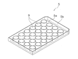
- FIG. 1 is a perspective view of a container body of a cell culture container.
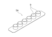
- 2 and 3 are perspective views of a plate with a pressing member of the cell culture container.
- the cell culture container 1 includes a container body 3 and a plate 5 with a pressing member.
- the container body 3 has a rectangular shape in plan view, and has a plurality of recesses (wells) 7 as cell culture cells for accommodating the cell culture solution C as a culture solution.
- the container body 3 is a transparent member having a small thickness, and is made of, for example, a transparent plastic.
- the container main body 3 is a well-known thing, for example, is a common well plate.
- the plate 5 with a pressing member has a rectangular shape corresponding to the container main body 3 and has a plurality of pressing members 9 corresponding to the recesses 7.
- the plate 5 with a pressing member is a thin member having a small thickness, and is made of, for example, a transparent plastic.
- the plate 5 with a pressing member has a flat main body 5a and a frame 5b formed on the outer peripheral surface thereof.
- a plurality of pressing members 9 are provided on the main body 5a of the plate 5 with pressing members.
- the pressing member 9 is a member that is detachably fitted to the upper side of the recess 7. 2 includes a total of 24 pressing members 9 of 6 ⁇ 4, and the pressing plate 5A illustrated in FIG. 3 includes a total of six pressing members 9 of 6 ⁇ 1. is doing.
- boards 5A with a pressing member shown in FIG. 3 are used with respect to the container main body 3 shown in FIG.
- FIG. 4 is a cross-sectional view of the cell culture container. As shown in FIG. 4, in a state where the plate 5 with a pressing member is fitted in the container body 3, a plurality of pressing members 9 are respectively inserted into the plurality of recesses 7.
- the lid is covered from above the cell culture vessel 1 (that is, from above the plate 5 with a pressing member) during cell culture.
- the lid covers the upper portion of the container body 3 and the plate 5 with the pressing member. Thereby, the contamination with respect to a cell culture solution is prevented.
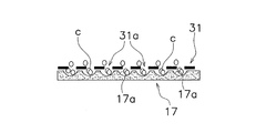
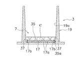
- FIG. 5 is a sectional view of the cell culture container
- FIG. 6 is a plan view of the membrane member.
- the concave portion 7 has a bottom portion 17 and a cylindrical portion 19.
- the inner peripheral surface 19a of the cylindrical portion 19 extends substantially vertically in the longitudinal section.
- the upper surface of the bottom 17 is non-cell adhesive.
- Cell non-adhesiveness refers to the property that adherent cells are difficult to adhere.
- polyethylene glycol, polyhydroxyethyl methacrylate, ethylene vinyl alcohol copolymer may be used as a highly hydrophilic substance.
- it may be coated with a surfactant or a phospholipid, or a surface treatment such as a plasma treatment may be performed.
- a plurality of microwells 17 a are formed on the upper surface of the bottom portion 17.
- the microwell 17a is a minute recess for forming a spheroid.
- the diameter of the microwell 17a is, for example, 30 to 1500 ⁇ m, and preferably 50 to 300 ⁇ m.
- the depth of the microwell 17a is, for example, 30 to 1500 ⁇ m, preferably 50 to 300 ⁇ m.
- the pressing member 9 mainly has a cylindrical portion 25 and a film-like member 31.
- the cylindrical portion 25 is fitted in the cylindrical portion 19 of the concave portion 7 with a slight gap. That is, the outer peripheral surface 25 a of the cylindrical portion 25 is opposed to the inner peripheral surface 19 a of the cylindrical portion 19 in a state of being close to the inner peripheral surface 19 a.
- the outer peripheral edge of the membrane member 31 is fixed to the lower end of the cylindrical portion 25.
- the film member 31 may be integrally formed with the tubular portion 25.
- the film-like member 31 is a member that is disposed above the microwell 17a in the recess 7 and restricts the movement so that the material grown in the microwell 17a does not leave the microwell 17a.
- the membranous member 31 has a shape or property that allows cell culture fluid to pass through.
- the membrane member 31 is a circular mesh member. Since the membrane member 31 is a mesh member, the cell culture solution can move to both sides throughout.
- a cell non-adhesion process is performed on the lower surface of the membrane member 31.
- the cell non-adhesion treatment is, for example, the same as described above. By this process, as will be described later, the spheroid S hardly adheres to the film member 31. In addition, the cell non-adhesion process does not necessarily need to be performed.
- the membrane member 31 is soluble.
- the film-like member 31 dissolves in one week, for example.
- the film-like member 31 is, for example, cross-linked gelatin, starch, or PVA. This makes it easier to take out the spheroid S as will be described later.
- the film-like member 31 does not necessarily need to be soluble. In that case, the film-like member 31 is made of, for example, nylon, PE, PP, carbon, PEEK, Teflon (registered trademark), PET, or metal.
- the size of the mesh gap of the film member 31 is, for example, 30 to 1500 ⁇ m.
- the dimension between the film member 31 and the upper surface of the bottom portion 17 is, for example, 50 to 300 ⁇ m.
- the dimension of the spheroid is 30 to 1500 ⁇ m, and the dimension of the mesh gap is adjusted according to the size.
- the size of the mesh gap is set so that the seed cell c can pass through, but the seed cell c may be set so as not to pass through. In this case, the seed cell c is seeded in the microwell 17a before the membrane member 31 is fixed.
- the pressing member 9 further has a flange portion 27.
- the flange portion 27 is described as a member fixed to the main body 5a of the plate 5 with a pressing member, but may be formed integrally with the main body 5a.
- the flange portion 27 extends from the tubular portion 25 to the outer peripheral side, and is seated on the upper surface of the tubular portion 19 of the recess 7.
- the pressing member 9 is provided with the flange portion 27, it is easy to remove the pressing member 9 from the recess 7.
- FIGS. 7 to 9 are schematic diagrams for explaining spheroid creation.
- seed cell c is seeded. Specifically, as shown in FIG. 7, the cell culture solution is injected into the recess 7.
- the cell culture medium is a suspension composed of a liquid medium and seed cells c that are uniformly diffused in the medium.
- the seed cell c has adhesiveness, and is, for example, a cancer cell such as a human osteosarcoma cell or a hepatocyte.
- As the medium a known medium suitable for culturing adherent cells is used. In the above case, individual seed cells c descend to the microwells 17a through the gaps 31a of the membrane member 31 and land.
- spheroids S are formed by aggregation of a plurality of seed cells c in the microwell 17a.
- the membrane member 31 is disposed above the plurality of microwells 17a in the recess 7, and movement is restricted so that the spheroid S grown in the microwells 17a does not leave the microwell 17a. is doing. Therefore, the spheroid S is stably formed in the cell culture container 1.
- a new culture medium can be inject
- the nutrients and oxygen are supplied to the cells during the culture by the medium circulation, and the cells grow healthy.
- a large spheroid S requiring a relatively long culture period can be formed, and the formed spheroid S can be stored for a long time.
- the cell waste and waste which did not become spheroid S are removed by medium exchange.
- the spheroid S is exposed by melting the membrane member 31. Thereby, it becomes easy to take out the spheroid S.
- the state of FIG. 9 is obtained by removing the film-shaped member.
- the membranous member is not limited to a mesh member as having a shape through which a cell culture solution can pass.
- the film-like member 31 ⁇ / b> A is a circular film in which a plurality of minute holes 31 b are formed as a whole.
- the film-like member 31A is made of, for example, glass, a plastic film, or a plastic plate.
- the plurality of minute holes 31b are formed by a laser, for example.
- the membrane member is not limited to a mesh member as having a shape through which a cell culture solution can pass.
- the film-like member 31B is a circular member in which a plurality of small holes 31c are formed.
- the film member 31B is made of the same material as the film member 31A.
- the plurality of small holes 31c are arranged annularly on the outer peripheral side.
- the shape, position, and number of holes are not particularly limited. However, when a plurality of small holes are formed only on the outer peripheral side of the membrane member as shown in FIG. 11, the observation accuracy of the spheroid S is improved in the microwells corresponding to the central portion and the middle portion of the membrane member. .
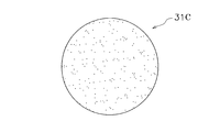
- the membranous member 31 is not limited to those of the first embodiment and the second embodiment as having the property of allowing cell culture fluid to pass through.
- the film-like member 31C is made of hydrogel.
- Hydrogel is a polymer material having a property of swelling when it contains a large amount of moisture.
- the hydrogel is made of, for example, acrylamide, silicone, agarose, or gelatin. Thereby, the cell culture solution can pass through the membrane member 31C. It should be noted that the hydrogel may have a structure capable of circulating proteins (about 1 to 20 nm).
- the seeding of cells is performed before the installation of the membrane member 31C.
- the reason is that the membranous member 31C passes through the medium but does not pass through the cells.
- what has a property which a cell culture solution can pass as a membranous member is not limited to hydrogel.
- the membranous member has a shape or property that allows the cell culture medium to pass through.
- the membranous member is grown in the microwell from the microwell. Since it is only necessary to restrict movement so as not to leave, it is not limited to the above.
- the membranous member may have a shape or property that prevents cell culture fluid from passing through. The above contents will be described with reference to FIG. FIG. 13 is a cross-sectional view of the cell culture container.
- the film-like member 35 is disposed at a position close to the upper surface of the bottom 17 of the recess 7.
- the membrane member 35 has a property that the cell culture solution cannot pass therethrough.
- An annular gap 35 a is secured between the outer peripheral edge of the film-like member 35 and the lower part of the inner peripheral surface 19 a of the cylindrical portion 19.
- the gap between the membrane member 35 and the upper surface of the bottom 17 of the recess 7 is such that one cell can pass but spheroids cannot pass.
- the gap is 10 ⁇ m or more and 100 ⁇ m or less.
- the dimension of the spheroid is 30 to 1500 ⁇ m, and the dimension of the gap is adjusted according to the size.
- the film member 35 is fixed to the bottom portion 17 by a plurality of fixing pins 37.
- the fixing pin 37 is attached to the outer peripheral portion of the membrane member 35, and the tip is inserted into the mounting hole 17 b of the bottom portion 17.
- the film member 35 is a transparent film.
- the film member 35 is made of, for example, nylon, PE, PP, carbon, PEEK, Teflon (registered trademark), or PET.
- the cell culture solution passes through the gap 35a, and a space between the membrane member 35 and the bottom portion 17 (that is, spheroid S is formed in the microwell 17a). It is possible to move inside and outside the space. That is, the medium can be exchanged while the spheroid S is held by the membrane member 35. By exchanging the medium, nutrients and oxygen are supplied to the cells during the cultivation, and the cells grow healthy. Moreover, the cell waste and waste which did not become spheroid S are removed by medium exchange.
- the same effect as in the first to fourth embodiments can be obtained.
- the modification of each embodiment is applicable to this embodiment suitably.
- the film-like member 35 is transparent, the spheroid S can be observed with a microscope.
- FIG. 14 is a cross-sectional view of a cell culture device.
- the film-like member 39 is disposed at a position close to the upper surface of the bottom 17 of the recess 7.
- the membranous member 39 has a shape or property that prevents the culture medium from passing therethrough.
- the outer peripheral edge of the film-like member 39 is fixed to the lower part of the inner peripheral surface 19 a of the cylindrical portion 19.
- a plurality of holes 39 a are formed on the outer periphery of the film-like member 39.
- the cell culture solution passes through the plurality of holes 39a, and the spheroid S is formed in the space between the membrane member 35 and the bottom portion 17 (that is, in the microwell 17a). Can be moved in and out of the space.
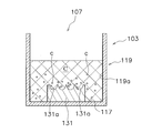
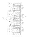
- FIGS. 15 to 19 are cross-sectional views of the cell culture container.
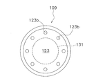
- FIG. 20 is a top view of the pressing member.
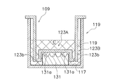
- FIG. 15 shows the container body 103 of the cell culture container.
- the container main body 103 is a container having a recess 107 whose upper side is open, and holds the cell culture medium C.
- the cell culture medium C contains a large number of seed cells c.
- a microwell member 131 is installed on the bottom 117 of the recess 107.
- the microwell member 131 is a member having a plurality of microwells 131a on the upper surface.
- the microwell member 131 is provided at the center of the bottom portion 117, and the upper surface thereof is disposed relatively far from the bottom portion 117. Therefore, the bottom portion 117 has a lower surface than the upper surface of the microwell member 131 on the outer peripheral side of the microwell member 131.
- the pressing member 109 is inserted into the recess 107 of the container main body 103.
- the pressing member 109 has a disk-like lower surface portion 123 as a film-like member.
- the lower surface portion 123 is disposed close to the upper surface of the microwell member 131 (the portion where the microwell 131a is formed).
- a plurality of bubble discharge portions 123 b are formed on the outer peripheral side of the microwell member 131. That is, the bubble discharge part 123b is provided corresponding to a part of the bottom part 117 where the plurality of microwells 131a are not formed.
- the bubble discharge part 123b is a dot-like through hole. Therefore, bubbles in a space below the lower surface portion 123 (for example, around the plurality of microwells 131a and the microwell member 131) are easily discharged to the outside.
- spheroids S are formed in the intent of the microwell 131a.
- the lower surface portion 123 is disposed close to the microwell 131a, the grown spheroid S cannot go out of the microwell 131a. Therefore, the spheroid S can be formed safely and reliably.
- the cell culture solution C is reduced so that the cell culture solution C does not exist above the lower surface 123, and the spheroid S is observed from below the container body 103.
- the lower surface 123a of the lower surface portion 123 comes into contact with the upper surface of the cell culture medium C, so that the meniscus is eliminated.
- the spheroid S can be accurately observed in the container body 103.
- the bubble discharge portion is a plurality of holes, but the form of the bubble discharge portion is not limited thereto.
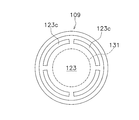
- FIG. 20 is a top view of the pressing member.
- a plurality of bubble discharge portions 123 c are formed on the outer peripheral side of the microwell member 131.
- the bubble discharge part 123c is an arc-shaped through groove extending in the circumferential direction.
- release part is not limited to the through-hole formed in a lower surface part.
- the bubble releasing part may be a notch, a slit, or a through hole formed between the cylindrical part 125 of the pressing member 109 and the cylindrical part 119 of the container main body 103.
- the lower surface portion of the pressing member has a flat shape, but the shape of the lower surface portion is not particularly limited. Another embodiment of the pressing member 109 will be described with reference to FIG.
- FIG. 21 is a cross-sectional view of a cell culture container.
- the pressing member 109 has a flat lower surface portion 123A and an annular protruding portion 123B.
- the lower surface portion 123A is disposed close to the upper surface of the microwell member 131.
- the annular protrusion 123B is formed on the outer peripheral edge of the lower surface 123A and extends downward. That is, the protrusion 123 ⁇ / b> B is disposed so as to surround the outer peripheral side of the microwell member 131.
- a plurality of bubble discharge portions 123b are formed on the bottom surface of the protruding portion 123B.
- the shape of the bubble discharge part 123b is a dot-shaped or arc-shaped through-hole or a combination thereof.
- FIG. 22 is a cross-sectional view of the cell culture container.
- a lid 11 is disposed above the plate 5 with a pressing member.
- the lid 11 covers the entire upper side of the plate 5 with a pressing member.
- the lid 11 has a flat main body 11a and a cylindrical portion 11b extending downward from the outer peripheral edge thereof.
- a cushion member 12 is disposed between the main body 11a of the lid 11 and the plate 5 with a pressing member.
- the cushion member 12 is an elastic member such as a spring, rubber, or sponge.
- the cushion member 12 generates an elastic force by being compressed between the plate 5 with a pressing member and the lid 11. Thereby, it is prevented that the board 5 with a pressing member floats, and it can fix in the container main body 3.
- FIG. Thereby, for example, when forming a spheroid, the clearance gap between a microwell and a mesh can be ensured correctly, and, thereby, the spheroid fixing effect is acquired reliably.
- FIG. 23 is a cross-sectional view of a cell culture container.
- the basic structure is the same as in the tenth embodiment.
- a first engagement portion 15 is formed on the outer peripheral portion of the container body 3, and a second engagement portion 16 is formed on the cylindrical portion 11 b of the lid 11. The first engaging portion 15 and the second engaging portion 16 are engaged with each other, so that the lid 11 is not separated from the container body 3.
- the cushion member 12 generates an elastic force by being compressed between the plate 5 with a pressing member and the lid 11. Thereby, it is prevented that the board 5 with a pressing member floats, and it can fix in the container main body 3.
- FIG. Thereby, for example, even in the case of forming spheroids, the gap between the microwell and the mesh can be sufficiently shortened, and thereby the spheroid fixing effect can be reliably obtained.
- the lift of the plate 5 with the pressing member is prevented by using a lid and a cushion member, but the lift can be prevented by other means.
- the plate 5 with pressing member itself is made heavy by using a metal material for a part.
- a weight is attached to a part of the plate 5 with the pressing member.
- FIG. 24 is a cross-sectional view of the cell culture container.
- a pin member 41 is fixed to the lower surface of the flange 27 portion of the plate 5 with a pressing member. The lower end of the pin member 41 is inserted into a hole 43 formed in the upper surface of the cylindrical portion 19 of the container body 3.
- the vertical positioning of the pressing member 9 and the recess 7 is accurately performed by the pin and the hole. Therefore, the gap between the film-like member 31 and the upper surface of the bottom portion 17 is accurately ensured.
- the number, shape, and position of the positioning structure using the pins and holes are not particularly limited.
- FIG. 25 is a cross-sectional view of the cell culture container.
- a plurality of protrusions 45 are provided at the lower end of the cylindrical portion 19.
- the protrusion 45 extends further downward than the film member 31.
- the lower end of the protrusion 45 is inserted into a mounting hole 17 b formed on the upper surface of the bottom portion 17.
- the vertical positioning of the pressing member 9 and the concave portion 7 is accurately performed by the protrusion and the hole. Therefore, the gap between the film-like member 31 and the upper surface of the bottom portion 17 is accurately ensured.
- the number, shape, and position of the positioning structure using the protrusions and holes are not particularly limited.
- the positioning between the lower portion and the bottom portion of the cylindrical portion is not limited to the above embodiment.
- the lower part of the cylindrical part may be supported by a receiving part provided at the bottom.
- FIG. 26 is a perspective view of the container body of the cell culture container.
- the basic structure is the same as in the first to fifteenth embodiments. Hereinafter, different points will be mainly described.
- a plurality of pins 71 are erected at the upper corner of the container body 3. Specifically, the pins 71 are arranged at the four corners of the outer portion of the main body portion where the concave portion 7 of the container main body 3 is formed.
- a hole 73 is formed in the plate 5 with a pressing member at a position corresponding to the pin 71. Specifically, the holes 73 are formed at the four corners of the frame 5b.
- the plurality of pressing members 9 are smoothly fitted into the recesses 7 by positioning with the pins 71 and the holes 73.
- the number of pins and holes is not limited to the above embodiment.
- the positioning structure of the container main body 3 and the plate 5 with a pressing member is not limited to pins and holes.
- a culture container for example, cell culture container 1 includes a container main body (for example, container main body 3) and a film-shaped member (for example, film-shaped member 31, film-shaped member 31A, film-shaped member 31B, film-shaped member 31C, membrane). Member 35, film member 39, lower surface portion 123, lower surface portion 123A).
- the container body 3 has a plurality of microwells (for example, a plurality of microwells 17a and microwells 131a) for containing a culture medium (for example, cell culture medium C), and a bottom surface (for example, an upper surface of the bottom portion 17, a microwell member).
- the film-like member is a member that is disposed above the plurality of microwells in the recess and restricts movement so that spheroids (for example, spheroid S) grown in the microwell do not leave the microwell.
- the membrane member is disposed above the plurality of microwells in the recess, and movement is restricted so that spheroids grown in the microwell do not separate from the microwell (for example, FIG. 8). , See FIG. Therefore, spheroids are stably formed in the culture container.
- the present invention is not limited thereto.
- the present invention can also be applied to, for example, embryoid body culture.
- the embryoid body is a cell mass composed of ES cells, iPS cells and the like having a structure similar to that of the early embryo.
- the medium is exchanged during spheroid formation, but the medium exchange is not necessarily performed.
- the shape of the concave portion and the pressing member in a plan view and the combination thereof are not limited to the above embodiment.
- the number of recesses and pressing members is not limited to the above embodiment.
- the cell culture container using the cell culture solution has been described as an example of the culture container.
- animal cells, plant cells, fungi, and bacteria can be cultured in the culture container according to the present invention.
- the present invention can be widely applied to a culture vessel that contains a culture solution used for microscopic observation.
Abstract
Description
また、目的に合った容器を用いて培養を行うために、様々な形状及びサイズの培養容器が開発されている。 In the fields of medicine and living organisms, culture of cells and fungi is widely performed.
Moreover, in order to perform culture | cultivation using the container suitable for the objective, the culture container of various shapes and sizes is developed.
スフェロイドを形成する方法として、複数の凹部を有する培養容器に細胞の懸濁液を注入して、各凹部においてスフェロイドを形成する技術が知られている(例えば、特許文献1を参照)。 In particular, in recent years, cell spheroids (hereinafter referred to as spheroids) created by culturing in three dimensions are attracting attention, unlike conventional planar cell cultures, in order to fully demonstrate the functions inherent to cells. Has been. A spheroid is a three-dimensional structure formed by cells adhering to each other using the cell adhesion function of the cells.
As a method of forming spheroids, a technique is known in which a cell suspension is injected into a culture vessel having a plurality of recesses to form spheroids in each recess (see, for example, Patent Document 1).
この培養容器では、膜状部材が、凹部内で複数のマイクロウェルの上方に配置され、マイクロウェル内で成長したスフェロイドが当該マイクロウェルから離脱しないように移動を制限している。したがって、培養容器においてスフェロイドが安定的に形成される。 A culture container according to an aspect of the present invention includes a container body and a membrane member. The container body has a recess in which a plurality of microwells for containing a culture solution are formed on the bottom surface. The film-like member is a member that is disposed above the plurality of microwells in the recess and restricts movement so that spheroids grown in the microwell do not leave the microwell.
In this culture container, the membrane-like member is disposed above the plurality of microwells in the recess, and movement is restricted so that spheroids grown in the microwell do not separate from the microwell. Therefore, spheroids are stably formed in the culture container.
この場合、複数のマイクロウェル内の培養液を容易に交換できる。 The membranous member may have a shape or property through which the culture solution can pass.
In this case, the culture solutions in the plurality of microwells can be easily exchanged.
この場合、膜状部材のいずれの箇所でも培養液が通過可能であるので、複数のマイクロウェル内の培養液を効率よく交換できる。 The film member may have a mesh structure.
In this case, since the culture solution can pass through any part of the membrane member, the culture solution in the plurality of microwells can be exchanged efficiently.
この場合、スフェロイドが膜状部材の下面に接着しにくくなっており、その結果、スフェロイドが膜状部材の下面に接着されにくい。 The lower surface of the membrane member may be subjected to cell non-adhesion treatment.
In this case, the spheroids are difficult to adhere to the lower surface of the membrane member, and as a result, the spheroids are less likely to adhere to the lower surface of the membrane member.
この場合、スフェロイドが形成された後に、膜状部材が溶けてなくなる。そのため、膜状部材を取り除く作業が不要になる。つまり、スフェロイドの取り出しが容易になる。 The membrane member may be soluble.
In this case, after the spheroid is formed, the film-like member is not melted. This eliminates the need to remove the membrane member. That is, the spheroid can be easily taken out.
この場合、筒状部材を凹部に出し入れすることで、膜状部材の設置及び取り外しができる。その結果、作業性が向上する。 The culture vessel may be further provided with a cylindrical member that can be inserted into the recess and has a membrane-like member provided at the bottom.
In this case, the membrane member can be installed and removed by taking the cylindrical member into and out of the recess. As a result, workability is improved.
この場合、膜状部材に培養液が通過するものを用いていない場合でも、複数のマイクロウェル内の培養液を交換できる。 A gap may be secured between the bottom surface and the lower surface of the membrane member so that the culture solution can move inside and outside each microwell.
In this case, even when the membrane member does not use a material through which the culture solution passes, the culture solution in the plurality of microwells can be replaced.
(1)全体構造
図1~図3を用いて、本発明の一実施形態としての培養容器としての細胞培養容器1を説明する。
図1は、細胞培養容器の容器本体の斜視図である。図2及び図3は、細胞培養容器の押さえ部材付き板の斜視図である。 1. First Embodiment (1) Overall Structure A
FIG. 1 is a perspective view of a container body of a cell culture container. 2 and 3 are perspective views of a plate with a pressing member of the cell culture container.
なお、図2に示す押さえ部材付き板5は6×4合計24個の押さえ部材9を有しており、図3に示す押さえ部材付き板5Aは6×1合計6個の押さえ部材9を有している。図3に示す押さえ部材付き板5Aは、図1に示す容器本体3に対しては4個が用いられる。 The
2 includes a total of 24
次に、図5及び図6を用いて、凹部7と押さえ部材9の構造及び両者の関係を詳細に説明する。図5は細胞培養容器の断面図であり、図6は膜状部材の平面図である。 (2) Detailed structure Next, the structure of the recessed
この実施形態では、膜状部材31は可溶性である。膜状部材31は、例えば、1週間で溶解する。膜状部材31は、例えば、架橋したゼラチン、デンプン、PVAである。これによって、後述するようにスフェロイドSを取り出しやすくなる。なお、膜状部材31は必ずしも可溶性でなくてもよい。その場合は、膜状部材31は、例えば、ナイロン、PE、PP、カーボン、PEEK、テフロン(登録商標)、PET、金属からなる。 In this embodiment, a cell non-adhesion process is performed on the lower surface of the
In this embodiment, the
なお、上記施形態ではメッシュ隙間の寸法は、種細胞cが通過可能に設定されていたが、種細胞cが通過不能に設定されてもよい。この場合は、種細胞cは、膜状部材31の固定前にマイクロウェル17aに播種される。 The size of the mesh gap of the
In the above embodiment, the size of the mesh gap is set so that the seed cell c can pass through, but the seed cell c may be set so as not to pass through. In this case, the seed cell c is seeded in the
図7~図9を用いて、スフェロイドSを作成する工程を説明する。図7~図9は、スフェロイド作成を説明するための模式図である。
最初に、種細胞cの播種を行う。具体的には、図7に示すように、細胞培養液を凹部7内に注入する。細胞培養液は、液体の培地と、培地に均一に拡散された種細胞cとからなる懸濁液である。種細胞cは、付着性を有しており、例えば、ヒト骨肉腫細胞などのガン細胞や肝細胞である。培地は、付着性細胞の培養に適した公知のものが用いられる。以上の場合、個々の種細胞cが、膜状部材31の隙間31aを通って、マイクロウェル17aにまで降下し着床する。 (3) Spheroid creation process The process of creating the spheroid S will be described with reference to FIGS. 7 to 9 are schematic diagrams for explaining spheroid creation.
First, seed cell c is seeded. Specifically, as shown in FIG. 7, the cell culture solution is injected into the
上記の培地交換において、凹部7内において培地の流れが生じるが、このとき、膜状部材31によってスフェロイドSを押さえているので、スフェロイドSがマイクロウェル17aから飛び出さない。したがって、スフェロイドSの流出が防止されている。 You may provide the apparatus which supplies and discharge | emits a culture medium inside the recessed
In the culture medium exchange described above, a culture medium flows in the
膜状部材は、細胞培養液が通過可能な形状を有しているものとしては、メッシュ部材に限定されない。
図10に示すように、膜状部材31Aは、複数の微小孔31bが全体に形成された円形のフィルムである。
膜状部材31Aは、例えば、ガラス、プラチックフィルム、プラスチック板からなる。複数の微小孔31bは例えばレーザによって形成される。 2. Second Embodiment The membranous member is not limited to a mesh member as having a shape through which a cell culture solution can pass.
As shown in FIG. 10, the film-
The film-
膜状部材は、細胞培養液が通過可能な形状を有しているものとしては、メッシュ部材に限定されない。
図11に示すように、膜状部材31Bは、複数の小孔31cが形成された円形の部材である。膜状部材31Bは、膜状部材31Aと同じ材料である。この実施形態では、複数の小孔31cは、外周側において、環状に配置されている。孔の形状、位置、個数は特に限定されない。ただし、図11のように複数の小孔が膜状部材の外周側にのみ形成されている場合は、膜状部材の中心部及び中間部に対応するマイクロウェルにおいてスフェロイドSの観察精度が向上する。 3. Third Embodiment The membrane member is not limited to a mesh member as having a shape through which a cell culture solution can pass.
As shown in FIG. 11, the film-
膜状部材31は、細胞培養液が通過可能な性質を有しているものとしては、第1実施形態及び第2実施形態のものに限定されない。
図12に示すように、膜状部材31Cは、ハイドロゲルから構成されている。ハイドロゲルとは、水分を多量に含むことにより膨潤する性質を有する高分子材料である。ハイドロゲルは、例えば、アクリルアミド、シリコーン、アガロース、ゼラチンからなる。これにより、細胞培養液は膜状部材31Cを通過可能である。なお、ハイドロゲルでは、タンパク質(1~20nm程度)の循環が可能な構造であればよい。 4). Fourth Embodiment The
As shown in FIG. 12, the film-
なお、膜状部材として細胞培養液が通過可能な性質を有しているものは、ハイドロゲルに限定されない。 In this case, the seeding of cells is performed before the installation of the
In addition, what has a property which a cell culture solution can pass as a membranous member is not limited to hydrogel.
第1~第4実施形態では膜状部材は細胞培養液が通過可能な形状又は性質を有していたが、膜状部材は、マイクロウェル内で成長したものが当該マイクロウェルから離脱しないように移動を制限さえできればよいので、上記のものに限定されない。例えば、膜状部材は細胞培養液が通過不能な形状又は性質を有していてもよい。
図13を用いて、上記の内容を説明する。図13は、細胞培養容器の断面図である。 5. Fifth Embodiment In the first to fourth embodiments, the membranous member has a shape or property that allows the cell culture medium to pass through. However, the membranous member is grown in the microwell from the microwell. Since it is only necessary to restrict movement so as not to leave, it is not limited to the above. For example, the membranous member may have a shape or property that prevents cell culture fluid from passing through.
The above contents will be described with reference to FIG. FIG. 13 is a cross-sectional view of the cell culture container.
膜状部材35と凹部7の底部17の上面との隙間は、細胞1個は通過可能であるが、スフェロイドは通過不能な寸法である。例えば、隙間は、10μm以上であり、かつ100μm以下である。なお、スフェロイドの寸法は、30~1500μmであり、そのサイズに合わせて隙間の寸法は調整される。 As shown in the figure, the film-
The gap between the
膜状部材35は、透明フィルムである。膜状部材35は、例えば、ナイロン、PE、PP、カーボン、PEEK、テフロン(登録商標)、PETからなる。 The
The
さらに、膜状部材35が透明であるので、スフェロイドSを顕微鏡で観察可能である。 In this embodiment, the same effect as in the first to fourth embodiments can be obtained. Moreover, the modification of each embodiment is applicable to this embodiment suitably.
Furthermore, since the film-
膜状部材を底部の近傍に取り付ける構造は、第5実施形態のものに限定されない。
図14を用いて、そのような実施形態を説明する。図14は、細胞培養器の断面図である。 6). Sixth Embodiment The structure for attaching the film-like member near the bottom is not limited to that of the fifth embodiment.
Such an embodiment will be described with reference to FIG. FIG. 14 is a cross-sectional view of a cell culture device.
膜状部材39は、外周縁が筒状部19の内周面19aの下部に固定されている。また、膜状部材39の外周には、複数の孔39aが形成されている。 As shown in the figure, the film-
The outer peripheral edge of the film-
第1~第6実施形態では底部にマイクロウェルを形成した容器を用いたが、マイクロウェルが形成される部材は上記の構成に限定されない。
図15~図19を用いて、スフェロイド形成用の細胞培養容器を説明する。図15~図19は細胞培養容器の断面図である。図20は、押さえ部材の上面図である。 7). Seventh Embodiment In the first to sixth embodiments, a container having a microwell formed at the bottom is used, but the member on which the microwell is formed is not limited to the above-described configuration.
A cell culture container for spheroid formation will be described with reference to FIGS. 15 to 19 are cross-sectional views of the cell culture container. FIG. 20 is a top view of the pressing member.
凹部107の底部117には、マイクロウェル部材131が設置されている。マイクロウェル部材131は、複数のマイクロウェル131aを上面に有する部材である。 FIG. 15 shows the
A
第7実施形態では気泡放出部は複数の孔であったが、気泡放出部の形態はそれに限定されない。
図20を用いて、押さえ部材の他の実施形態を説明する。図20は、押さえ部材の上面図である。下面部123において、マイクロウェル部材131よりさらに外周側の部分には複数の気泡放出部123cが形成されている。気泡放出部123cは、円周方向に延びる弧状の貫通溝である。 8). Eighth Embodiment In the seventh embodiment, the bubble discharge portion is a plurality of holes, but the form of the bubble discharge portion is not limited thereto.
Another embodiment of the pressing member will be described with reference to FIG. FIG. 20 is a top view of the pressing member. In the
また、気泡放出部は、下面部に形成される貫通孔に限定されない。気泡放出部は、押さえ部材109の筒状部125と容器本体103の筒状部119との間に形成された切り欠き、スリット、貫通孔であってもよい。 There are no particular limitations on the shape, number, and position of the through-holes that are formed in the lower surface portion as the bubble emitting portion.
Moreover, a bubble discharge | release part is not limited to the through-hole formed in a lower surface part. The bubble releasing part may be a notch, a slit, or a through hole formed between the
第7実施形態では押さえ部材の下面部は平坦な形状であったが、下面部の形状は特に限定されない。
図21を用いて、押さえ部材109の他の実施形態を説明する。図21は、細胞培養容器の断面図である。 9. Ninth Embodiment In the seventh embodiment, the lower surface portion of the pressing member has a flat shape, but the shape of the lower surface portion is not particularly limited.
Another embodiment of the
第1~第9実施形態では押さえ部材の下面部とその下方の部材との間の寸法を正確に管理することが求められる。しかし、押さえ部材は培養容器の培地に押し込んで使用されるので、浮力で押さえ部材が浮いてしまうという問題が考えられる。
そこで、図22を用いて、そのような課題を解決するための構造を説明する。図22は、細胞培養容器の断面図である。 10. Tenth Embodiment In the first to ninth embodiments, it is required to accurately manage the dimension between the lower surface portion of the pressing member and the member below the pressing member. However, since the pressing member is used by being pushed into the culture medium of the culture vessel, there is a problem that the pressing member floats due to buoyancy.
Therefore, a structure for solving such a problem will be described with reference to FIG. FIG. 22 is a cross-sectional view of the cell culture container.
第12実施形態では、蓋は自重のみによって弾性部材を圧縮していたが、他の構造によって弾性部材を圧縮してもよい。
そこで、図23を用いて、そのような課題を解決するための構造を説明する。図23は、細胞培養容器の断面図である。 11. Eleventh Embodiment In the twelfth embodiment, the lid compresses the elastic member only by its own weight, but the elastic member may be compressed by another structure.
Therefore, a structure for solving such a problem will be described with reference to FIG. FIG. 23 is a cross-sectional view of a cell culture container.
この実施形態では、容器本体3の外周部に第1係合部15が形成され、さらに蓋11の筒状部11bに第2係合部16が形成されている。第1係合部15と第2係合部16は互いに係合しており、それにより蓋11が容器本体3から離れないようになっている。 The basic structure is the same as in the tenth embodiment.
In this embodiment, a
第10実施形態及び第11実施形態では、蓋及びクッション部材を用いることで押さえ部材付き板5の浮き上がりを防止していたが、他の手段によっても浮き上がり防止は可能である。例えば、押さえ部材付き板5の重量を増加することで、浮力による浮きを防止できる。具体的には、金属製材料を一部に使うことで、押さえ部材付き板5自体を重くする。又は、押さえ部材付き板5の一部に錘を付ける。 12 Twelfth Embodiment In the tenth embodiment and the eleventh embodiment, the lift of the
図24を用いて、筒状部19に固定された膜状部材31の位置決めを正確に行うための構造を説明する。図24は、細胞培養容器の断面図である。
押さえ部材付き板5のフランジ27部の下面には、ピン部材41が固定されている。ピン部材41の下端は、容器本体3の筒状部19の上面に形成された孔43内に挿入されている。 13 Thirteenth Embodiment A structure for accurately positioning the
A
なお、上記のピンと孔による位置決め構造は、個数、形状、位置が特に限定されない。 Thus, the vertical positioning of the
The number, shape, and position of the positioning structure using the pins and holes are not particularly limited.
図25を用いて、筒状部19に固定された膜状部材31の位置決めを正確に行うための構造を説明する。図25は、細胞培養容器の断面図である。
筒状部19の下端には、複数の突起45が設けられている。突起45は、膜状部材31よりさらに下方に延びている。突起45の下端は、底部17の上面に形成された取付孔17b内に挿入されている。 14 Fourteenth Embodiment A structure for accurately positioning the
A plurality of
なお、上記の突起と孔による位置決め構造は、個数、形状、位置が特に限定されない。また、筒状部の下部と底部との間の位置決めは前記実施形態に限定されない。例えば、筒状部の下部が底部に設けられた受け部によって支持されてもよい。 Thus, the vertical positioning of the
Note that the number, shape, and position of the positioning structure using the protrusions and holes are not particularly limited. Further, the positioning between the lower portion and the bottom portion of the cylindrical portion is not limited to the above embodiment. For example, the lower part of the cylindrical part may be supported by a receiving part provided at the bottom.
複数の押さえ部材が複数の凹部にスムーズに嵌まるように両者に位置決め構造を説明する。 15. Fifteenth Embodiment A positioning structure will be described for the plurality of pressing members so that the plurality of pressing members fit smoothly into the plurality of recesses.
なお、基本的な構造は第1~第15実施形態と同じである。以下、異なる点を中心に説明する。 Such an embodiment will be described with reference to FIG. FIG. 26 is a perspective view of the container body of the cell culture container.
The basic structure is the same as in the first to fifteenth embodiments. Hereinafter, different points will be mainly described.
押さえ部材付き板5には、ピン71に対応する位置に孔73が形成されている。具体的には、孔73は、枠5bの四隅に形成されている。 A plurality of
A
なお、ピンと孔の数は前記実施形態に限定されない。さらに、容器本体3と押さえ部材付き板5との位置決め構造は、ピンと孔に限定されない。 When the
The number of pins and holes is not limited to the above embodiment. Furthermore, the positioning structure of the container
第1~第15実施形態は下記の点が共通である。
培養容器(例えば、細胞培養容器1)は、容器本体(例えば、容器本体3)と、膜状部材(例えば、膜状部材31、膜状部材31A、膜状部材31B、膜状部材31C、膜状部材35、膜状部材39、下面部123、下面部123A)と、を備えている。容器本体3は、培養液(例えば、細胞培養液C)を収容するための複数のマイクロウェル(例えば、複数のマイクロウェル17a、マイクロウェル131a)が底面(例えば、底部17の上面、マイクロウェル部材131の上面)に形成された凹部(例えば、凹部7、凹部107)を有する。膜状部材は、凹部内で複数のマイクロウェルの上方に配置され、マイクロウェル内で成長したスフェロイド(例えば、スフェロイドS)が当該マイクロウェルから離脱しないように移動を制限するための部材である。
この培養容器では、膜状部材が、凹部内で複数のマイクロウェルの上方に配置され、マイクロウェル内で成長したスフェロイドが当該マイクロウェルから離脱しないように移動を制限している(例えば、図8、図17参照。)。したがって、培養容器においてスフェロイドが安定的に形成される。 16. Common points of the embodiments The following points are common to the first to fifteenth embodiments.
A culture container (for example, cell culture container 1) includes a container main body (for example, container main body 3) and a film-shaped member (for example, film-shaped
In this culture container, the membrane member is disposed above the plurality of microwells in the recess, and movement is restricted so that spheroids grown in the microwell do not separate from the microwell (for example, FIG. 8). , See FIG. Therefore, spheroids are stably formed in the culture container.
以上、本発明の一実施形態について説明したが、本発明は上記実施形態に限定されるものではなく、発明の要旨を逸脱しない範囲で種々の変更が可能である。特に、本明細書に書かれた複数の実施形態及び変形例は必要に応じて任意に組み合せ可能である。 17. Other Embodiments Although one embodiment of the present invention has been described above, the present invention is not limited to the above embodiment, and various modifications can be made without departing from the scope of the invention. In particular, a plurality of embodiments and modifications described in this specification can be arbitrarily combined as necessary.
前記実施形態ではスフェロイド形成中に培地交換を行っていたが、培地交換は必ずしも行わなくてもよい。
凹部及び押さえ部材の平面視形状、及びそれらの組合せは前記実施形態に限定されない。
凹部及び押さえ部材の個数は、前記実施形態に限定されない。 Although the spheroid culture has been described in the above embodiment, the present invention is not limited thereto. The present invention can also be applied to, for example, embryoid body culture. The embryoid body is a cell mass composed of ES cells, iPS cells and the like having a structure similar to that of the early embryo.
In the above embodiment, the medium is exchanged during spheroid formation, but the medium exchange is not necessarily performed.
The shape of the concave portion and the pressing member in a plan view and the combination thereof are not limited to the above embodiment.
The number of recesses and pressing members is not limited to the above embodiment.
3 :容器本体
5 :押さえ部材付き板
5A :押さえ部材付き板
5a :本体
5b :枠
7 :凹部
9 :押さえ部材
17 :底部
17a :マイクロウェル
17b :取付孔
19 :筒状部
19a :内周面
25 :筒状部
25a :外周面
27 :フランジ部
31 :膜状部材
31A :膜状部材
31B :膜状部材
31C :膜状部材
31a :隙間
31b :微小孔
31c :小孔
35 :膜状部材
39 :膜状部材
123 :下面部
123A :下面部
123a :下面
C :細胞培養液
c :種細胞
S :スフェロイド 1: Cell culture vessel 3: Container body 5:
Claims (7)
- 培養液を収容するための複数のマイクロウェルが底面に形成された凹部を有する容器本体と、
前記凹部内で前記複数のマイクロウェルの上方に配置され、前記マイクロウェル内で成長したものが当該マイクロウェルから離脱しないように移動を制限するための膜状部材と、
を備えた培養容器。 A container body having a recess formed on the bottom surface with a plurality of microwells for containing a culture solution;
A film-like member disposed above the plurality of microwells in the recess and for restricting the movement so that the one grown in the microwell does not leave the microwell;
A culture vessel equipped with. - 前記膜状部材は、前記培養液が通過可能な形状又は性質を有している、請求項1に記載の培養容器。 The culture container according to claim 1, wherein the membrane member has a shape or a property through which the culture solution can pass.
- 前記膜状部材は、メッシュ構造を有している、請求項2に記載の培養容器。 The culture container according to claim 2, wherein the membranous member has a mesh structure.
- 前記膜状部材の下面には細胞非接着処理が施されている、請求項1~3のいずれかに記載の培養容器。 The culture vessel according to any one of claims 1 to 3, wherein a cell non-adhesion treatment is applied to the lower surface of the membrane member.
- 前記膜状部材は可溶性である、請求項1~4のいずれかに記載の培養容器。 The culture vessel according to any one of claims 1 to 4, wherein the membranous member is soluble.
- 前記凹部内に挿入可能であり、前記膜状部材が底部に設けられた筒状部材をさらに備えている、請求項1~5のいずれかに記載の培養容器。 The culture vessel according to any one of claims 1 to 5, further comprising a cylindrical member that can be inserted into the recess, and the membrane-like member is provided at the bottom.
- 前記底面と前記膜状部材の下面との間には隙間が確保されており、それにより前記培養液が各マイクロウェルの内外で移動可能である、請求項1に記載の培養容器。 The culture container according to claim 1, wherein a gap is secured between the bottom surface and the bottom surface of the membrane member, whereby the culture solution can move inside and outside each microwell.
Priority Applications (3)
| Application Number | Priority Date | Filing Date | Title |
|---|---|---|---|
| KR1020167011273A KR102353140B1 (en) | 2014-09-05 | 2015-06-10 | Culture vessel |
| US15/305,878 US20170051241A1 (en) | 2014-09-05 | 2015-06-10 | Culture container |
| EP15838513.8A EP3124591B1 (en) | 2014-09-05 | 2015-06-10 | Culture vessel |
Applications Claiming Priority (2)
| Application Number | Priority Date | Filing Date | Title |
|---|---|---|---|
| JP2014-181187 | 2014-09-05 | ||
| JP2014181187A JP5731704B1 (en) | 2014-09-05 | 2014-09-05 | Culture vessel |
Publications (1)
| Publication Number | Publication Date |
|---|---|
| WO2016035407A1 true WO2016035407A1 (en) | 2016-03-10 |
Family
ID=53486853
Family Applications (1)
| Application Number | Title | Priority Date | Filing Date |
|---|---|---|---|
| PCT/JP2015/066713 WO2016035407A1 (en) | 2014-09-05 | 2015-06-10 | Culture vessel |
Country Status (6)
| Country | Link |
|---|---|
| US (1) | US20170051241A1 (en) |
| EP (1) | EP3124591B1 (en) |
| JP (1) | JP5731704B1 (en) |
| KR (1) | KR102353140B1 (en) |
| TW (1) | TWI541345B (en) |
| WO (1) | WO2016035407A1 (en) |
Cited By (3)
| Publication number | Priority date | Publication date | Assignee | Title |
|---|---|---|---|---|
| WO2021230750A1 (en) * | 2020-05-15 | 2021-11-18 | Universiteit Leiden | Screening plate and method for co-culturing cells |
| WO2022034902A1 (en) * | 2020-08-12 | 2022-02-17 | 国立大学法人東京大学 | Device for reproducing renal filtration function, device for evaluating renal filtration function, and method for evaluating renal filtration function |
| US11377630B2 (en) | 2018-02-28 | 2022-07-05 | Glad I Kr Co., Ltd. | Cell culture kit |
Families Citing this family (12)
| Publication number | Priority date | Publication date | Assignee | Title |
|---|---|---|---|---|
| JP7070401B2 (en) * | 2016-04-18 | 2022-05-18 | 東洋製罐グループホールディングス株式会社 | How to use the cell culture container |
| JP2018000134A (en) * | 2016-07-06 | 2018-01-11 | 大日本印刷株式会社 | Cell culture container |
| US11618873B2 (en) | 2016-12-14 | 2023-04-04 | Hitachi High-Tech Corporation | Culture instrument |
| JP2018108032A (en) * | 2016-12-28 | 2018-07-12 | Agcテクノグラス株式会社 | Culture vessel |
| KR101934185B1 (en) | 2017-03-24 | 2018-12-31 | 중앙대학교 산학협력단 | Method for transferring sample |
| JP7023277B2 (en) * | 2017-03-31 | 2022-02-21 | 株式会社ナガヨシ | A culture vessel close to the in-vivo environment and a culture dish equipped with it |
| WO2019012622A1 (en) * | 2017-07-12 | 2019-01-17 | 次郎 大野 | Device for producing three-dimensional cell structure having arbitrary shape, and method for producing same |
| CN110576609A (en) * | 2018-06-07 | 2019-12-17 | 三纬国际立体列印科技股份有限公司 | Three-dimensional printing device and molding water tank thereof |
| KR102170803B1 (en) * | 2018-10-19 | 2020-10-27 | 주식회사 이지다이아텍 | Method for isolation and morphological analysis of cells |
| KR102224065B1 (en) * | 2018-12-28 | 2021-03-05 | 포항공과대학교 산학협력단 | Porous microwell and membrane with the porous microwell, and method for manufacturing the same |
| CN116783276A (en) * | 2020-12-28 | 2023-09-19 | 分子装置(奥地利)有限公司 | Microwell plate wells for cell culture |
| JP2022149254A (en) * | 2021-03-25 | 2022-10-06 | 豊田合成株式会社 | Cell culture container and cell culture method |
Citations (4)
| Publication number | Priority date | Publication date | Assignee | Title |
|---|---|---|---|---|
| JP2003180335A (en) * | 2001-12-21 | 2003-07-02 | Sumitomo Bakelite Co Ltd | Storable culture vessel |
| JP2009050194A (en) * | 2007-08-27 | 2009-03-12 | Sumitomo Bakelite Co Ltd | Vessel for cell aggregate-forming culture |
| JP2010158214A (en) * | 2009-01-09 | 2010-07-22 | Olympus Corp | Culture vessel |
| JP2012060903A (en) * | 2010-09-14 | 2012-03-29 | Kajixx Kk | Adhesive sheet for multiwell plate and cell culture method |
Family Cites Families (3)
| Publication number | Priority date | Publication date | Assignee | Title |
|---|---|---|---|---|
| US3767790A (en) * | 1972-02-11 | 1973-10-23 | Nat Patent Dev Corp | Microorganisms |
| JP5578779B2 (en) | 2008-10-08 | 2014-08-27 | 国立大学法人東北大学 | Spheroid culture method and spheroid culture vessel |
| EP2230014A1 (en) * | 2009-03-20 | 2010-09-22 | Mark Ungrin | Devices and methods for production of cell aggregates |
-
2014
- 2014-09-05 JP JP2014181187A patent/JP5731704B1/en active Active
-
2015
- 2015-06-10 EP EP15838513.8A patent/EP3124591B1/en active Active
- 2015-06-10 WO PCT/JP2015/066713 patent/WO2016035407A1/en active Application Filing
- 2015-06-10 KR KR1020167011273A patent/KR102353140B1/en active IP Right Grant
- 2015-06-10 US US15/305,878 patent/US20170051241A1/en not_active Abandoned
- 2015-07-31 TW TW104124827A patent/TWI541345B/en not_active IP Right Cessation
Patent Citations (4)
| Publication number | Priority date | Publication date | Assignee | Title |
|---|---|---|---|---|
| JP2003180335A (en) * | 2001-12-21 | 2003-07-02 | Sumitomo Bakelite Co Ltd | Storable culture vessel |
| JP2009050194A (en) * | 2007-08-27 | 2009-03-12 | Sumitomo Bakelite Co Ltd | Vessel for cell aggregate-forming culture |
| JP2010158214A (en) * | 2009-01-09 | 2010-07-22 | Olympus Corp | Culture vessel |
| JP2012060903A (en) * | 2010-09-14 | 2012-03-29 | Kajixx Kk | Adhesive sheet for multiwell plate and cell culture method |
Cited By (4)
| Publication number | Priority date | Publication date | Assignee | Title |
|---|---|---|---|---|
| US11377630B2 (en) | 2018-02-28 | 2022-07-05 | Glad I Kr Co., Ltd. | Cell culture kit |
| WO2021230750A1 (en) * | 2020-05-15 | 2021-11-18 | Universiteit Leiden | Screening plate and method for co-culturing cells |
| WO2022034902A1 (en) * | 2020-08-12 | 2022-02-17 | 国立大学法人東京大学 | Device for reproducing renal filtration function, device for evaluating renal filtration function, and method for evaluating renal filtration function |
| JP7470349B2 (en) | 2020-08-12 | 2024-04-18 | 国立大学法人 東京大学 | Renal filtration function reproducing device, renal filtration function evaluating device, and renal filtration function evaluating method |
Also Published As
| Publication number | Publication date |
|---|---|
| KR20170052524A (en) | 2017-05-12 |
| EP3124591A4 (en) | 2017-08-23 |
| JP2016054655A (en) | 2016-04-21 |
| JP5731704B1 (en) | 2015-06-10 |
| EP3124591B1 (en) | 2018-10-24 |
| US20170051241A1 (en) | 2017-02-23 |
| TWI541345B (en) | 2016-07-11 |
| TW201546269A (en) | 2015-12-16 |
| KR102353140B1 (en) | 2022-01-18 |
| EP3124591A1 (en) | 2017-02-01 |
Similar Documents
| Publication | Publication Date | Title |
|---|---|---|
| JP5731704B1 (en) | Culture vessel | |
| JP5768174B1 (en) | Culture vessel | |
| CN108026499B (en) | Device for propagating micro-tissue | |
| JP5950055B2 (en) | Cell mass culture vessel | |
| Lee et al. | A hollow sphere soft lithography approach for long-term hanging drop methods | |
| WO2010150521A1 (en) | Culture substrate, culture sheet, and cell culture method | |
| KR101522120B1 (en) | Culture substrate and culture sheet | |
| JP2016093149A (en) | Cell culture apparatus, and cell culture method | |
| JP6256853B1 (en) | Method for producing three-dimensional cell structure and support used therefor | |
| JP6431341B2 (en) | Method for culturing adherent cells | |
| US20190322972A1 (en) | Methods and apparatus for perfusion and environment control of microplate labware | |
| WO2016190322A1 (en) | Cell treatment container | |
| JP2011004612A (en) | Culture substrate, culture sheet and cell culture method | |
| JP6459219B2 (en) | Cell culture vessel | |
| JP2020523008A (en) | Lid for culture dish | |
| JP6382938B2 (en) | Cell culture jig and cell culture method using the cell culture jig | |
| Tenstad et al. | Extensive adipogenic and osteogenic differentiation of patterned human mesenchymal stem cells in a microfluidic device | |
| US20210292707A1 (en) | Method for the culturing of cells | |
| JP5730499B2 (en) | Incubation equipment | |
| JP6439115B2 (en) | How to develop and maintain the function of tissue fragments | |
| US20210277347A1 (en) | Cell culture vessel and cell chip | |
| JP2015126754A (en) | Culture substrate | |
| JP2021093930A (en) | Cell culture container, cell culture system, and spheroid culture method | |
| JP2015057079A (en) | Culture substrate |
Legal Events
| Date | Code | Title | Description |
|---|---|---|---|
| 121 | Ep: the epo has been informed by wipo that ep was designated in this application |
Ref document number: 15838513 Country of ref document: EP Kind code of ref document: A1 |
|
| ENP | Entry into the national phase |
Ref document number: 20167011273 Country of ref document: KR Kind code of ref document: A |
|
| WWE | Wipo information: entry into national phase |
Ref document number: 15305878 Country of ref document: US |
|
| REEP | Request for entry into the european phase |
Ref document number: 2015838513 Country of ref document: EP |
|
| WWE | Wipo information: entry into national phase |
Ref document number: 2015838513 Country of ref document: EP |
|
| NENP | Non-entry into the national phase |
Ref country code: DE |