WO2016021290A1 - Surgical instrument - Google Patents
Surgical instrument Download PDFInfo
- Publication number
- WO2016021290A1 WO2016021290A1 PCT/JP2015/065781 JP2015065781W WO2016021290A1 WO 2016021290 A1 WO2016021290 A1 WO 2016021290A1 JP 2015065781 W JP2015065781 W JP 2015065781W WO 2016021290 A1 WO2016021290 A1 WO 2016021290A1
- Authority
- WO
- WIPO (PCT)
- Prior art keywords
- guided
- guide groove
- jaw
- guide
- surgical instrument
- Prior art date
Links
- 0 CCC1=C=*=CCC1 Chemical compound CCC1=C=*=CCC1 0.000 description 1
Images


Classifications
-
- A—HUMAN NECESSITIES
- A61—MEDICAL OR VETERINARY SCIENCE; HYGIENE
- A61B—DIAGNOSIS; SURGERY; IDENTIFICATION
- A61B17/00—Surgical instruments, devices or methods, e.g. tourniquets
- A61B17/068—Surgical staplers, e.g. containing multiple staples or clamps
- A61B17/072—Surgical staplers, e.g. containing multiple staples or clamps for applying a row of staples in a single action, e.g. the staples being applied simultaneously
- A61B17/07207—Surgical staplers, e.g. containing multiple staples or clamps for applying a row of staples in a single action, e.g. the staples being applied simultaneously the staples being applied sequentially
-
- A—HUMAN NECESSITIES
- A61—MEDICAL OR VETERINARY SCIENCE; HYGIENE
- A61B—DIAGNOSIS; SURGERY; IDENTIFICATION
- A61B17/00—Surgical instruments, devices or methods, e.g. tourniquets
- A61B17/32—Surgical cutting instruments
-
- A—HUMAN NECESSITIES
- A61—MEDICAL OR VETERINARY SCIENCE; HYGIENE
- A61B—DIAGNOSIS; SURGERY; IDENTIFICATION
- A61B17/00—Surgical instruments, devices or methods, e.g. tourniquets
- A61B17/068—Surgical staplers, e.g. containing multiple staples or clamps
- A61B17/072—Surgical staplers, e.g. containing multiple staples or clamps for applying a row of staples in a single action, e.g. the staples being applied simultaneously
- A61B2017/07214—Stapler heads
- A61B2017/07221—Stapler heads curved
-
- A—HUMAN NECESSITIES
- A61—MEDICAL OR VETERINARY SCIENCE; HYGIENE
- A61B—DIAGNOSIS; SURGERY; IDENTIFICATION
- A61B17/00—Surgical instruments, devices or methods, e.g. tourniquets
- A61B17/068—Surgical staplers, e.g. containing multiple staples or clamps
- A61B17/072—Surgical staplers, e.g. containing multiple staples or clamps for applying a row of staples in a single action, e.g. the staples being applied simultaneously
- A61B2017/07214—Stapler heads
- A61B2017/07278—Stapler heads characterised by its sled or its staple holder
-
- A—HUMAN NECESSITIES
- A61—MEDICAL OR VETERINARY SCIENCE; HYGIENE
- A61B—DIAGNOSIS; SURGERY; IDENTIFICATION
- A61B17/00—Surgical instruments, devices or methods, e.g. tourniquets
- A61B17/068—Surgical staplers, e.g. containing multiple staples or clamps
- A61B17/072—Surgical staplers, e.g. containing multiple staples or clamps for applying a row of staples in a single action, e.g. the staples being applied simultaneously
- A61B2017/07214—Stapler heads
- A61B2017/07285—Stapler heads characterised by its cutter
-
- A—HUMAN NECESSITIES
- A61—MEDICAL OR VETERINARY SCIENCE; HYGIENE
- A61B—DIAGNOSIS; SURGERY; IDENTIFICATION
- A61B17/00—Surgical instruments, devices or methods, e.g. tourniquets
- A61B17/28—Surgical forceps
- A61B17/29—Forceps for use in minimally invasive surgery
- A61B2017/2901—Details of shaft
- A61B2017/2905—Details of shaft flexible
-
- A—HUMAN NECESSITIES
- A61—MEDICAL OR VETERINARY SCIENCE; HYGIENE
- A61B—DIAGNOSIS; SURGERY; IDENTIFICATION
- A61B17/00—Surgical instruments, devices or methods, e.g. tourniquets
- A61B17/28—Surgical forceps
- A61B17/29—Forceps for use in minimally invasive surgery
- A61B2017/2926—Details of heads or jaws
- A61B2017/2932—Transmission of forces to jaw members
- A61B2017/2933—Transmission of forces to jaw members camming or guiding means
- A61B2017/2937—Transmission of forces to jaw members camming or guiding means with flexible part
Definitions
- the present invention relates to a surgical instrument.
- This application claims priority based on Japanese Patent Application No. 2014-158914 filed in Japan on August 4, 2014, the contents of which are incorporated herein by reference.
- Patent Documents 1 and 2 disclose surgical instruments capable of moving a blade portion along a curved cartridge. However, these surgical instruments push and move the blade portion in order to move the blade portion along the curved shape of the cartridge. For this reason, the movement of the blade portion may meander without being smooth due to the frictional resistance between the cartridge and the knife and the hook of the blade portion against the cartridge.
- the present invention has been made in view of the above-described circumstances, and an object of the present invention is to provide a surgical instrument in which the movement of the blade portion in the tissue cutting process is smooth.
- the guide portion includes a groove-shaped first guide groove formed along the predetermined curved shape, and the first A second guide groove formed at a bottom of the guide groove and having a narrower width than the first guide groove, and the guided portion is in contact with an inner surface of the first guide groove.
- the root portion 3 is a substantially cylindrical portion that connects the cartridge portion 2 to the flexible tube 61.
- the proximal end of the root portion 3 is fixed to the distal end of the flexible tube 61.
- the distal end of the root portion 3 is connected to the opening / closing link portion 8 and the second jaw 50.
- connection member 5 that is operated by a user operation on the operation unit 63 is inserted into the root unit 3.
- the connection member 5 includes a first connection member 6 for opening and closing the first jaw 10 with respect to the second jaw 50 and a second connection member (wire) 7 for operating an operation unit 31 described later. .
- the proximal end of the first connection member 6 extends to the operation unit 63.
- the distal end of the first connection member 6 is connected to the opening / closing link portion 8.
- connection member 7a for separation is hung on a pulley portion 25 described later. Further, the separating connection member 7a is inserted into a guide portion 24 described later. The proximal end of the disconnecting connection member 7 a extends to the operation unit 63.
- the base portion 11 is a substantially rod-shaped or channel-shaped member having a longitudinal axis and a shape that follows the curved shape of the first jaw 10.
- the base part 11 has a recess 12 and a communication path 13 to the base part 3.
- the concave portion 12 can accommodate the staple holder 15 and the operating portion 31.
- the concave portion 12 is opened toward the second gripping surface 51 side of the second jaw 50.
- the recess 12 has a bottom formed by a cover 14.
- the communication path 13 to the root portion 3 is a path through which the second connection member 7 is inserted.
- the staple holder 15 includes a holder body portion 16, a pulley portion 25 (see FIG. 5), and a driver 26.
- the staple holder 15 can be attached to and detached from the base portion 11.
- the used staple holder 15 can be removed from the base portion 11 after stitching using the staples 27.
- a new staple holder 15 is attached to the base 11 in place of the used staple holder 15, whereby suturing using the surgical instrument 1 according to the present embodiment can be performed a plurality of times.
- the guide portion 24 has a groove shape wider than the interval between the first wall surface 23 a and the second wall surface 23 b.
- the first guided portion 34 and the second guided portion 35 of the pair of guided portions 33 provided in the operating portion 31 can contact the guide portion 24.
- the cam portion 37 has an inclined surface 38 that is inclined with respect to the longitudinal axis of the base portion 11.
- the inclined surface 38 of the cam portion 37 contacts the driver 26 and moves the driver 26 when the cam portion 37 moves in the longitudinal axis direction of the base portion 11.
- the moving direction of the cam portion 37 is a direction in which the groove portion 22 extends.
- the staple holder 15, the staple 27, the cam portion 37, and the second jaw 50 constitute a stitching (joining) portion 54 (see FIG. 3) for stitching (joining) tissue.
- the flexible tube 61 is an elongated cylindrical member.
- the connection member 5 (the first connection member 6, the disconnecting connection member 7a, and the return connecting member 7b) is inserted into the flexible tube 61.
- the operation unit 63 is provided at the proximal end of the flexible tube 61.
- the operation unit 63 is provided for the user to perform an operation of opening and closing the first jaw 10 and the second jaw 50, attaching the staple 27 to the tissue, and further cutting the tissue.
- the shape of the operation unit 63 is a substantially bar shape that the operator can hold in the hand.
- the opening / closing knob 66 is a member for moving the first connection member 6 forward and backward in the direction of the center line thereof.
- the open / close knob 66 can be rotated with respect to the casing 64 of the operation unit 63 and can be fixed so as not to rotate with respect to the casing 64 at an arbitrary position.
- FIG. 14 is a cross-sectional view showing the cartridge portion of the surgical instrument 1A according to this embodiment, and shows a cross section taken along line III-III in FIG.
- FIG. 15 is a perspective view showing the operating portion 31 provided in the cartridge portion of the present embodiment.
- FIG. 16 is a diagram for explaining the operation of the surgical instrument 1A according to the present embodiment.
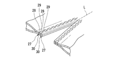
- the blade part 39 disposed in the center between the first guided part 34 and the second guided part 35 is The direction is the same as in the first embodiment.
- the blade portion 39 is connected to the central axis of the first guide groove 24A1. It is easier to bite inward than when the center axis of the two guide grooves 24A2 coincides.
- the blade portion 39 described in the first embodiment is closer to the first guided portion 34, that is, closer to the distal portion of the operating portion 31 than in the first embodiment.
- the guide portion 24A is formed so that the central axis of the second guide groove 24A2 is positioned on the outer peripheral side of the central axis of the first guide groove 24A1. do it.
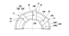
- the first guide groove 24B1 and the second guide groove 24B2 are spaced apart from each other, and may have curved shapes that are different from each other in order to adjust the orientation of the blade portion 39 as in the second embodiment.
- the first guide groove 24B1 and the second guide groove 24B2 have an arc shape that forms a part of concentric circles having different radii.
- the first guided portion 34B is guided by the first guide groove 24B1 in contact with the inner surface of the first guide groove 24B1.
- the same effects as in the first embodiment are obtained.
- operation part 31 seen along the direction where the groove part 22 is extended can be made shorter than 1st Embodiment.
- the opening and closing operation in the cartridge part 2 and the structure by the blade part 39 of the operating part 31 are shown. It may be configured such that the disconnection is performed in one operation. For example, when the operating part 31 is moved to the distal side of the cartridge part 2 using the lever 67, the operating part 31 connects the first jaw 10 and the second jaw 50, and the first jaw 10 is moved to the second side. You may be comprised so that it may move to the jaw 50 side. In this case, the opening / closing operation in the cartridge portion 2 and the tissue separation by the blade portion 39 of the operating portion 31 can be performed by one operation using the lever 67.
Abstract
Description
たとえば、特許文献1から3には、複数のステープルが収納されたカートリッジと、生体組織を切離するための刃部と、ステープルを組織に打ち込むとともに刃部により組織を切離するための操作部とを備えた手術用器具が開示されている。 2. Description of the Related Art Conventionally, an instrument that simultaneously sutures and separates biological tissue is known.
For example, in
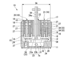
本発明の第1実施形態について説明する。図1は、本実施形態に係る手術用器具1の全体図である。図2は、手術用器具1のカートリッジ部2を示す模式図であり、図1に示す矢印A方向から見た図である。図3は、図2のIII-III線における断面図である。図4は、カートリッジ部2の一部を示す斜視図である。図5は、カートリッジ部2の部分断面図であり、図1に示す矢印B方向から見た図である。図6は、カートリッジ部2に設けられた作動部31を示す斜視図である。図7は、作動部31の斜視図である。図8は、作動部31の分解斜視図である。図9は、カートリッジ部2の第二ジョー50を示す斜視図である。 (First embodiment)
A first embodiment of the present invention will be described. FIG. 1 is an overall view of a
手術用器具1は、体内に挿入可能な挿入部62と、挿入部62に接続された操作部63とを備える。
挿入部62は、ステープル27が装填されたカートリッジ部2と、カートリッジ部2に接続された可撓管61とを備える。 The
The
The
根本部3の近位端は、可撓管61の遠位端に固定されている。根本部3の遠位端は、開閉リンク部8及び第二ジョー50に接続されている。 As shown in FIGS. 1 and 2, the
The proximal end of the
土台部11は、凹部12と、根本部3への連通路13とを有する。凹部12は、ステープルホルダ15及び作動部31を収容可能である。凹部12は、第二ジョー50の第二把持面51側に向かって開口されている。凹部12には、カバー14によって底が形成されている。
根本部3への連通路13は、図5に示すように、第二接続部材7が挿通される通路である。 As shown in FIG. 3, the
The
As shown in FIG. 5, the
図3に示すように、第一把持面17のうち、複数の収容部18を囲む包絡線の内側領域は、ステープル27によって組織が縫合される縫合領域SAを規定する。収容部18にステープル27が収容された状態において、溝部22によって分断されたホルダ体部16の2つの領域にそれぞれステープル列19(第一ステープル列20,第二ステープル列21)が構成される。 The
As shown in FIG. 3, the inner region of the envelope surrounding the plurality of
これにより、ステープル列19は、第一ジョー10から第二ジョー50に向かって発射可能な複数のステープル27を溝部22の周囲に有している。 The second
Thus, the
溝部22は、貫通孔部23と、ガイド部24とを有する。貫通孔部23は、第一把持面17に開口する。ガイド部24は、貫通孔部23と連なってホルダ体部16内に形成されている。 As shown in FIG. 3, the
The
図6,7,8に示すように、作動部31は、基台32と、一対の被ガイド部33と、カム部37と、刃部39とを有する。 6, 7, and 8 is disposed inside the
As shown in FIGS. 6, 7, and 8, the operating
基台32には、一対の被ガイド部33、カム部37及び刃部39が取り付けられている。 The
A pair of guided
一対の被ガイド部33は、基台32における遠位側に配された第一被ガイド部34と、基台32における近位側に配された第二被ガイド部35とを有する。 The pair of guided
The pair of guided
第二把持面51には、上記の成形ポケット52と、逃げ溝53とが形成されている。逃げ溝53は、刃部39の突出端が進入可能で第二ジョー50の長手軸方向に長く形成されている。 The second
The second
また、可撓管61には、縫合部位を観察するための公知の観察装置(たとえば内視鏡)を操作部63側からカートリッジ部2側まで案内するための管路が設けられていてもよい。 The proximal end of the
Further, the
手術用器具1は、図3に示すように収容部18にステープル27が収容され、土台部11の近位端近傍にカム部37及び刃部39が位置した状態で用意されている。図5に示すように、この時、作動部31の一対の被ガイド部33は、ガイド部24の近位端近傍に配置される。
手術用器具1は、公知の手技により、たとえば患者の口等の患者の自然開口や、患者の腹壁等に形成された小切開部分を通じて処置対象部位まで案内される。
図10に示すように、手術用器具1の挿入部62の遠位端部に設けられた第一ジョー10及び第二ジョー50は、不図示の腹腔鏡視下で、操作部63の開閉ノブ66(図1参照)の操作に応じて切離対象となる組織を把持する。 Next, the operation of the surgical instrument according to this embodiment will be described. 10 to 13 are views for explaining the operation of the
As shown in FIG. 3, the
The
As shown in FIG. 10, the
第二被ガイド部35についても第一被ガイド部34と同様に回動可能であることにより、強い力で戻し用接続部材7bが牽引されても戻し用接続部材7bが損傷しにくい。 As shown in FIG. 12, when the operating
Since the second guided
本実施形態に係る手術用器具1を用いて複数回の処置をする場合には、ステープル27を発射した後の新たなステープルホルダ15に交換して縫合及び切離を継続できる。 In addition, the
When a plurality of treatments are performed using the
次に、本発明の第2実施形態について説明する。なお、以下に説明する各実施形態において、第1実施形態で説明済みの構成要素と同様の構成要素には、第1実施形態と同一の符号が付され、重複する説明は省略される。図14は、本実施形態に係る手術用器具1Aのカートリッジ部を示す断面図で、図2のIII-III線における断面を示す。図15は、本実施形態のカートリッジ部に設けられた作動部31を示す斜視図である。図16は、本実施形態に係る手術用器具1Aの作用を説明するための図である。 (Second Embodiment)
Next, a second embodiment of the present invention will be described. In each embodiment described below, the same components as those already described in the first embodiment are denoted by the same reference numerals as those in the first embodiment, and redundant descriptions are omitted. FIG. 14 is a cross-sectional view showing the cartridge portion of the
また、第一ガイド溝24A1の中心軸よりも外周側に第二ガイド溝24A2の中心軸が位置するようにガイド部24Aを形成すると、刃部39は、第一ガイド溝24A1の中心軸と第二ガイド溝24A2の中心軸とが一致している時よりも、内側に食い込みやすい向きになる。逆に、第一ガイド溝24A1の中心軸よりも内周側に第二ガイド溝24A2の中心軸が位置するようにガイド部24Aを形成すると、刃部39は、第一ガイド溝24A1の中心軸と第二ガイド溝24A2の中心軸とが一致している時よりも、外側に食い込みやすい向きになる。 For example, as shown in FIG. 16, when there is a second guide groove 24A2 in the center of the first guide groove 24A1, the
In addition, when the
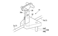
次に、本発明の第3実施形態について説明する。図18は本実施形態に係る手術用器具のカートリッジ部に設けられた作動部31を示す斜視図である。図19は、本実施形態に係る手術用器具の作用を説明するための図である。
本実施形態に係る手術用器具は、第1実施形態で説明したガイド部24及び被ガイド部33が異なる。本実施形態のガイド部24Bは、互いに平行な第一ガイド溝24B1及び第二ガイド溝24B2を有する。本実施形態の一対の被ガイド部33Bは、互いに平行(略平行を含む)な第一被ガイド部34B及び第二被ガイド部35Bを有する。 (Third embodiment)
Next, a third embodiment of the present invention will be described. FIG. 18 is a perspective view showing an operating
The surgical instrument according to the present embodiment is different in the
本実施形態では、第一ガイド溝24B1と第二ガイド溝24B2とは、互いに半径が異なる同心円の一部をなす円弧状である。 The first guide groove 24B1 and the second guide groove 24B2 are spaced apart from each other, and may have curved shapes that are different from each other in order to adjust the orientation of the
In the present embodiment, the first guide groove 24B1 and the second guide groove 24B2 have an arc shape that forms a part of concentric circles having different radii.
上記各実施形態では、可撓管61を備えた軟性の手術用器具1が例示されているが、可撓管61に代えて硬性のシャフトが設けられていてもよい。 For example, in the first embodiment described above, a configuration in which a total of four points including two spaced points in the first guided
In each of the above embodiments, the flexible
7a 切離用接続部材(ワイヤ)
10 第一ジョー
24、24A、24B ガイド部
24A1 第一ガイド溝
24A2 第二ガイド溝
31 作動部
32 基台
33、33B 一対の被ガイド部
34、34B 第一被ガイド部
35、35B 第二被ガイド部
39 刃部
50 第二ジョー
54 縫合部(接合部)
62 挿入部 1,
10
62 Insertion part
Claims (4)
- 体内に挿入可能な挿入部と、
組織を把持するために前記挿入部の遠位端部に設けられて所定の湾曲形状を有する第一ジョー及び第二ジョーと、
前記第一ジョーと前記第二ジョーとによって把持された組織を接合する接合部と、
前記所定の湾曲形状に沿って形成され前記第一ジョーに配されたガイド部と、
前記ガイド部に係合し互いに離間した位置に設けられ前記ガイド部に当接可能な4つの被ガイド部,前記被ガイド部と連なる基台、及び前記基台に固定された刃部を有する作動部と、
前記ガイド部の近位端部から遠位端部へ向かって延び前記ガイド部の遠位端部において折り返されて前記ガイド部の近位端部へ向かって延びて前記作動部に連結されたワイヤと、
を備えた手術用器具。 An insertion section that can be inserted into the body,
A first jaw and a second jaw provided at a distal end of the insertion portion for grasping tissue and having a predetermined curved shape;
A joint for joining tissues grasped by the first jaw and the second jaw;
A guide portion formed along the predetermined curved shape and disposed on the first jaw;
An operation having four guided portions that are engaged with the guide portion and are spaced apart from each other and that can contact the guide portion, a base that is connected to the guided portion, and a blade portion that is fixed to the base. And
A wire that extends from the proximal end portion of the guide portion toward the distal end portion, is folded at the distal end portion of the guide portion, extends toward the proximal end portion of the guide portion, and is connected to the operating portion. When,
Surgical instrument equipped with. - 前記ガイド部は、
前記所定の湾曲形状に沿って形成された溝状の第一ガイド溝と、
前記第一ガイド溝の底に形成され前記第一ガイド溝よりも幅が狭い第二ガイド溝と、
を備え、
前記被ガイド部は、
前記第一ガイド溝の内面に接して前記第一ガイド溝によりガイドされる第一被ガイド部と、
前記第二ガイド溝の内面に接して前記第一ガイド溝によりガイドされる第二被ガイド部と、
を備える
請求項1に記載の手術用器具。 The guide portion is
A groove-shaped first guide groove formed along the predetermined curved shape;
A second guide groove formed at the bottom of the first guide groove and narrower than the first guide groove;
With
The guided portion is
A first guided portion in contact with the inner surface of the first guide groove and guided by the first guide groove;
A second guided portion in contact with the inner surface of the second guide groove and guided by the first guide groove;
The surgical instrument according to claim 1. - 前記ガイド部は、
前記所定の湾曲形状に沿って形成された溝状の第一ガイド溝と、
前記第一ガイド溝から離間した位置で前記第一ガイド溝と平行に設けられた第二ガイド溝と、
を備え、
前記被ガイド部は、
前記第一ガイド溝の内面に接して前記第一ガイド溝によりガイドされる第一被ガイド部と、
前記第二ガイド溝の内面に接して前記第一ガイド溝によりガイドされる第二被ガイド部と、
を備える
請求項1に記載の手術用器具。 The guide portion is
A groove-shaped first guide groove formed along the predetermined curved shape;
A second guide groove provided in parallel with the first guide groove at a position spaced from the first guide groove;
With
The guided portion is
A first guided portion in contact with the inner surface of the first guide groove and guided by the first guide groove;
A second guided portion in contact with the inner surface of the second guide groove and guided by the first guide groove;
The surgical instrument according to claim 1. - 前記被ガイド部は前記基台に対して回転可能であり、
前記ワイヤは前記被ガイド部に接続されている
請求項1に記載の手術用器具。 The guided portion is rotatable relative to the base;
The surgical instrument according to claim 1, wherein the wire is connected to the guided portion.
Priority Applications (4)
| Application Number | Priority Date | Filing Date | Title |
|---|---|---|---|
| JP2016521810A JP6072365B2 (en) | 2014-08-04 | 2015-06-01 | Surgical instruments |
| EP15829378.7A EP3178410B1 (en) | 2014-08-04 | 2015-06-01 | Surgical instrument |
| CN201580037736.9A CN106488747B (en) | 2014-08-04 | 2015-06-01 | Utensil is used in operation |
| US15/402,783 US9782190B2 (en) | 2014-08-04 | 2017-01-10 | Surgical instrument |
Applications Claiming Priority (2)
| Application Number | Priority Date | Filing Date | Title |
|---|---|---|---|
| JP2014158914 | 2014-08-04 | ||
| JP2014-158914 | 2014-08-04 |
Related Child Applications (1)
| Application Number | Title | Priority Date | Filing Date |
|---|---|---|---|
| US15/402,783 Continuation US9782190B2 (en) | 2014-08-04 | 2017-01-10 | Surgical instrument |
Publications (1)
| Publication Number | Publication Date |
|---|---|
| WO2016021290A1 true WO2016021290A1 (en) | 2016-02-11 |
Family
ID=55263568
Family Applications (1)
| Application Number | Title | Priority Date | Filing Date |
|---|---|---|---|
| PCT/JP2015/065781 WO2016021290A1 (en) | 2014-08-04 | 2015-06-01 | Surgical instrument |
Country Status (5)
| Country | Link |
|---|---|
| US (1) | US9782190B2 (en) |
| EP (1) | EP3178410B1 (en) |
| JP (1) | JP6072365B2 (en) |
| CN (1) | CN106488747B (en) |
| WO (1) | WO2016021290A1 (en) |
Cited By (1)
| Publication number | Priority date | Publication date | Assignee | Title |
|---|---|---|---|---|
| CN109310420A (en) * | 2016-04-01 | 2019-02-05 | 伊西康有限责任公司 | Including can profiled shaft surgical stapling system |
Families Citing this family (6)
| Publication number | Priority date | Publication date | Assignee | Title |
|---|---|---|---|---|
| US8827903B2 (en) | 2011-03-14 | 2014-09-09 | Ethicon Endo-Surgery, Inc. | Modular tool heads for use with circular surgical instruments |
| US11284890B2 (en) | 2016-04-01 | 2022-03-29 | Cilag Gmbh International | Circular stapling system comprising an incisable tissue support |
| US10307159B2 (en) | 2016-04-01 | 2019-06-04 | Ethicon Llc | Surgical instrument handle assembly with reconfigurable grip portion |
| US10675021B2 (en) | 2016-04-01 | 2020-06-09 | Ethicon Llc | Circular stapling system comprising rotary firing system |
| US10376263B2 (en) | 2016-04-01 | 2019-08-13 | Ethicon Llc | Anvil modification members for surgical staplers |
| CN113825455A (en) | 2019-04-30 | 2021-12-21 | 波士顿科学国际有限公司 | Endoscopic patch applicator |
Citations (4)
| Publication number | Priority date | Publication date | Assignee | Title |
|---|---|---|---|---|
| JPH0630945A (en) * | 1992-05-19 | 1994-02-08 | Olympus Optical Co Ltd | Suturing apparatus |
| JPH08289895A (en) * | 1995-04-21 | 1996-11-05 | Olympus Optical Co Ltd | Suture device |
| JP2008220930A (en) * | 2007-01-11 | 2008-09-25 | Ethicon Endo Surgery Inc | Automatic surgical stapler end effector equipped with tapered distal end |
| JP2009034487A (en) * | 2007-06-18 | 2009-02-19 | Ethicon Endo Surgery Inc | Surgical stapling/cutting instrument improved in anvil opening feature part |
Family Cites Families (3)
| Publication number | Priority date | Publication date | Assignee | Title |
|---|---|---|---|---|
| US5389098A (en) * | 1992-05-19 | 1995-02-14 | Olympus Optical Co., Ltd. | Surgical device for stapling and/or fastening body tissues |
| US8348131B2 (en) | 2006-09-29 | 2013-01-08 | Ethicon Endo-Surgery, Inc. | Surgical stapling instrument with mechanical indicator to show levels of tissue compression |
| US7988028B2 (en) | 2008-09-23 | 2011-08-02 | Tyco Healthcare Group Lp | Surgical instrument having an asymmetric dynamic clamping member |
-
2015
- 2015-06-01 JP JP2016521810A patent/JP6072365B2/en active Active
- 2015-06-01 WO PCT/JP2015/065781 patent/WO2016021290A1/en active Application Filing
- 2015-06-01 EP EP15829378.7A patent/EP3178410B1/en active Active
- 2015-06-01 CN CN201580037736.9A patent/CN106488747B/en active Active
-
2017
- 2017-01-10 US US15/402,783 patent/US9782190B2/en active Active
Patent Citations (4)
| Publication number | Priority date | Publication date | Assignee | Title |
|---|---|---|---|---|
| JPH0630945A (en) * | 1992-05-19 | 1994-02-08 | Olympus Optical Co Ltd | Suturing apparatus |
| JPH08289895A (en) * | 1995-04-21 | 1996-11-05 | Olympus Optical Co Ltd | Suture device |
| JP2008220930A (en) * | 2007-01-11 | 2008-09-25 | Ethicon Endo Surgery Inc | Automatic surgical stapler end effector equipped with tapered distal end |
| JP2009034487A (en) * | 2007-06-18 | 2009-02-19 | Ethicon Endo Surgery Inc | Surgical stapling/cutting instrument improved in anvil opening feature part |
Cited By (1)
| Publication number | Priority date | Publication date | Assignee | Title |
|---|---|---|---|---|
| CN109310420A (en) * | 2016-04-01 | 2019-02-05 | 伊西康有限责任公司 | Including can profiled shaft surgical stapling system |
Also Published As
| Publication number | Publication date |
|---|---|
| JP6072365B2 (en) | 2017-02-01 |
| US9782190B2 (en) | 2017-10-10 |
| EP3178410A4 (en) | 2018-07-18 |
| CN106488747B (en) | 2019-08-20 |
| EP3178410B1 (en) | 2020-03-04 |
| US20170119420A1 (en) | 2017-05-04 |
| JPWO2016021290A1 (en) | 2017-04-27 |
| CN106488747A (en) | 2017-03-08 |
| EP3178410A1 (en) | 2017-06-14 |
Similar Documents
| Publication | Publication Date | Title |
|---|---|---|
| JP6006460B2 (en) | Surgical instrument and tissue separation unit | |
| JP6072365B2 (en) | Surgical instruments | |
| JP6245852B2 (en) | Surgical instruments and bushings | |
| US8858574B2 (en) | Suturing instrument | |
| JP5721978B2 (en) | Surgical stapler | |
| US7810690B2 (en) | Surgical stapling instrument | |
| AU2003257977B2 (en) | Placing sutures | |
| US20100038403A1 (en) | Surgical instrument and actuating movement transmitting device therefore | |
| JPH0630945A (en) | Suturing apparatus | |
| JP2008006299A (en) | Grasping instrument | |
| JP7107555B2 (en) | forceps | |
| JP2012075604A (en) | Therapeutic instrument | |
| JP2000201939A (en) | Medical implement | |
| US11612390B2 (en) | Suturing closure scope with alternative needle orientation | |
| JP7077964B2 (en) | Suture device | |
| JP7079450B2 (en) | Suture device | |
| JP4838946B2 (en) | Suture tool | |
| JP2017012532A (en) | Clip unit for ligation device and cartridge for clip unit | |
| JPH08280700A (en) | Surgical appliance | |
| JP2006230958A (en) | Surgical operation instrument | |
| JP2018064883A (en) | Changeover-type laparoscopic operation forceps |
Legal Events
| Date | Code | Title | Description |
|---|---|---|---|
| 121 | Ep: the epo has been informed by wipo that ep was designated in this application |
Ref document number: 15829378 Country of ref document: EP Kind code of ref document: A1 |
|
| ENP | Entry into the national phase |
Ref document number: 2016521810 Country of ref document: JP Kind code of ref document: A |
|
| NENP | Non-entry into the national phase |
Ref country code: DE |
|
| REEP | Request for entry into the european phase |
Ref document number: 2015829378 Country of ref document: EP |
|
| WWE | Wipo information: entry into national phase |
Ref document number: 2015829378 Country of ref document: EP |