WO2016017566A1 - Glass - Google Patents
Glass Download PDFInfo
- Publication number
- WO2016017566A1 WO2016017566A1 PCT/JP2015/071199 JP2015071199W WO2016017566A1 WO 2016017566 A1 WO2016017566 A1 WO 2016017566A1 JP 2015071199 W JP2015071199 W JP 2015071199W WO 2016017566 A1 WO2016017566 A1 WO 2016017566A1
- Authority
- WO
- WIPO (PCT)
- Prior art keywords
- region
- boundary
- area
- glass
- wedge angle
- Prior art date
Links
Images


Classifications
-
- B—PERFORMING OPERATIONS; TRANSPORTING
- B32—LAYERED PRODUCTS
- B32B—LAYERED PRODUCTS, i.e. PRODUCTS BUILT-UP OF STRATA OF FLAT OR NON-FLAT, e.g. CELLULAR OR HONEYCOMB, FORM
- B32B17/00—Layered products essentially comprising sheet glass, or glass, slag, or like fibres
- B32B17/06—Layered products essentially comprising sheet glass, or glass, slag, or like fibres comprising glass as the main or only constituent of a layer, next to another layer of a specific material
- B32B17/10—Layered products essentially comprising sheet glass, or glass, slag, or like fibres comprising glass as the main or only constituent of a layer, next to another layer of a specific material of synthetic resin
- B32B17/10005—Layered products essentially comprising sheet glass, or glass, slag, or like fibres comprising glass as the main or only constituent of a layer, next to another layer of a specific material of synthetic resin laminated safety glass or glazing
- B32B17/1055—Layered products essentially comprising sheet glass, or glass, slag, or like fibres comprising glass as the main or only constituent of a layer, next to another layer of a specific material of synthetic resin laminated safety glass or glazing characterized by the resin layer, i.e. interlayer
- B32B17/10559—Shape of the cross-section
- B32B17/10568—Shape of the cross-section varying in thickness
-
- B—PERFORMING OPERATIONS; TRANSPORTING
- B32—LAYERED PRODUCTS
- B32B—LAYERED PRODUCTS, i.e. PRODUCTS BUILT-UP OF STRATA OF FLAT OR NON-FLAT, e.g. CELLULAR OR HONEYCOMB, FORM
- B32B17/00—Layered products essentially comprising sheet glass, or glass, slag, or like fibres
- B32B17/06—Layered products essentially comprising sheet glass, or glass, slag, or like fibres comprising glass as the main or only constituent of a layer, next to another layer of a specific material
- B32B17/10—Layered products essentially comprising sheet glass, or glass, slag, or like fibres comprising glass as the main or only constituent of a layer, next to another layer of a specific material of synthetic resin
- B32B17/10005—Layered products essentially comprising sheet glass, or glass, slag, or like fibres comprising glass as the main or only constituent of a layer, next to another layer of a specific material of synthetic resin laminated safety glass or glazing
- B32B17/10009—Layered products essentially comprising sheet glass, or glass, slag, or like fibres comprising glass as the main or only constituent of a layer, next to another layer of a specific material of synthetic resin laminated safety glass or glazing characterized by the number, the constitution or treatment of glass sheets
- B32B17/10036—Layered products essentially comprising sheet glass, or glass, slag, or like fibres comprising glass as the main or only constituent of a layer, next to another layer of a specific material of synthetic resin laminated safety glass or glazing characterized by the number, the constitution or treatment of glass sheets comprising two outer glass sheets
-
- G—PHYSICS
- G02—OPTICS
- G02B—OPTICAL ELEMENTS, SYSTEMS OR APPARATUS
- G02B27/00—Optical systems or apparatus not provided for by any of the groups G02B1/00 - G02B26/00, G02B30/00
- G02B27/01—Head-up displays
- G02B27/0101—Head-up displays characterised by optical features
-
- B—PERFORMING OPERATIONS; TRANSPORTING
- B32—LAYERED PRODUCTS
- B32B—LAYERED PRODUCTS, i.e. PRODUCTS BUILT-UP OF STRATA OF FLAT OR NON-FLAT, e.g. CELLULAR OR HONEYCOMB, FORM
- B32B2605/00—Vehicles
- B32B2605/006—Transparent parts other than made from inorganic glass, e.g. polycarbonate glazings
-
- G—PHYSICS
- G02—OPTICS
- G02B—OPTICAL ELEMENTS, SYSTEMS OR APPARATUS
- G02B27/00—Optical systems or apparatus not provided for by any of the groups G02B1/00 - G02B26/00, G02B30/00
- G02B27/01—Head-up displays
- G02B27/0101—Head-up displays characterised by optical features
- G02B2027/0118—Head-up displays characterised by optical features comprising devices for improving the contrast of the display / brillance control visibility
- G02B2027/012—Head-up displays characterised by optical features comprising devices for improving the contrast of the display / brillance control visibility comprising devices for attenuating parasitic image effects
- G02B2027/0121—Parasitic image effect attenuation by suitable positioning of the parasitic images
Definitions
- the present invention relates to glass.
- HUD head-up display
- the first is a fluoroscopic double image, which is caused by a strong light source such as a headlight of an oncoming vehicle at night. This is because the light beam incident on the windshield is reflected by the inside of the windshield and the secondary beam entering the eyes forms an angle with the primary beam, so that the light source looks double.
- a fluoroscopic double image which is caused by a strong light source such as a headlight of an oncoming vehicle at night. This is because the light beam incident on the windshield is reflected by the inside of the windshield and the secondary beam entering the eyes forms an angle with the primary beam, so that the light source looks double.
- the second is a reflection double image, which is due to HUD. This is because the secondary beam entering the eye after the HUD light source is reflected from the outside of the windshield forms an angle with the primary beam, so that the HUD image appears to be double.
- a perspective double image may be a problem in the HUD display area.
- a reflection double image becomes a main problem, and a perspective double image becomes a problem in a region outside the HUD display.
- This invention is made in view of said point, and makes it a subject to provide the glass which can reduce the perspective distortion which arises in the boundary of a HUD display area
- the present glass is a glass having an inner surface and an outer surface, and has a first region used in a head-up display and a second region not used in a head-up display adjacent to the first region, In the first region, the region closest to the boundary between the first region and the second region is the first region inner boundary side end, and in the second region, the region closest to the boundary is the second region inner boundary side end.
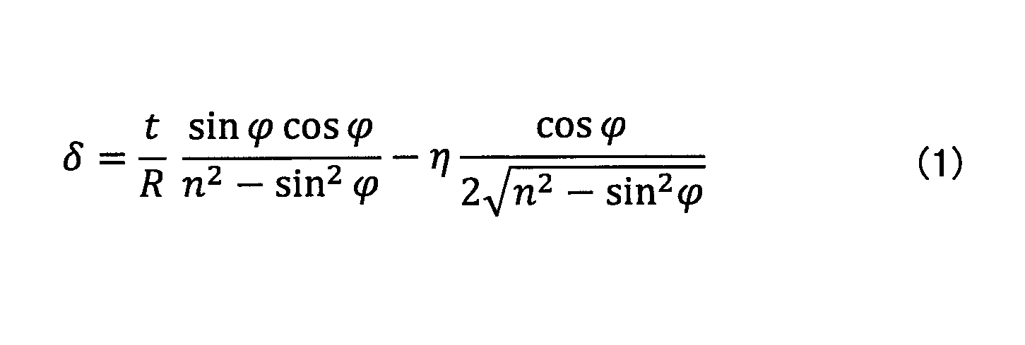
- the wedge angle ⁇ formed by the inner surface and the outer surface at each point of a partial region of the second region including the inner boundary side end of the second region satisfies the following formula (1). It is a requirement to do.
- the present invention it is possible to provide glass capable of reducing the perspective distortion generated at the boundary between the HUD display area and the HUD display outside area.
- FIG. (1) explaining the change of the wedge angle in a boundary.
- FIG. (2) explaining the change of the wedge angle in a boundary.
- FIG. (3) explaining the change of the wedge angle in a boundary.
- FIG. (4) explaining the change of the wedge angle in a boundary.
- FIG. 1A and 1B are diagrams for explaining the concept of a double image.
- FIG. 1A shows a reflection double image
- FIG. 1B shows a perspective double image.
- the front-rear direction of the vehicle on which the windshield 20 is mounted is X
- the left-right direction of the vehicle is Y
- the direction perpendicular to the XY plane is Z (the same applies to the following drawings).
- a part of the light beam 11a emitted from the HUD light source 10 is reflected by the inner surface 21 of the windshield 20 of the vehicle to generate a light beam 11b (primary beam) of the driver's eyes 30. And is viewed by the driver as an image 11c (virtual image) in front of the windshield 20.
- a part of the light beam 12 a emitted from the HUD light source 10 enters the inside from the inner surface 21 of the vehicle windshield 20 and is refracted, and a part thereof is reflected by the outer surface 22. Further, a part of the light exits from the inner surface 21 to the outside of the windshield 20 of the vehicle and is refracted to be guided to the driver's eyes 30 as a light beam 12b (secondary beam) and visually recognized by the driver as an image 12c (virtual image).
- the thickness of the windshield 20 is constant, and the inner surface 21 and the outer surface 22 are parallel.
- the two images 11c and 12c visually recognized by the driver are reflection double images.
- the angle formed between the light beam 11b (primary beam) and the light beam 12b (secondary beam) is the angle ⁇ of the reflected double image.
- the angle ⁇ of the reflected double image is preferably closer to zero.
- a part of the light beam 41a emitted from the light source 40 enters the inside from the outer surface 22 of the vehicle windshield 20 and is refracted.
- a part of the light exits from the inner surface 21 to the outside of the windshield 20 and is guided to the driver's eyes 30 as a light beam 41b and is visually recognized by the driver as an image 41c.
- a part of the light beam 42 a emitted from the light source 40 enters the inside from the outer surface 22 of the vehicle windshield 20 and is refracted, and a part thereof is reflected by the inner surface 21. Further, a part of the light is reflected by the outer surface 22, and a part of the light is further refracted to be refracted from the inner surface 21 to the outside of the windshield 20, and is guided to the driver's eye 30 as a light ray 42b to drive as an image 42c. Visible to the person.
- the two images 41c and 42c visually recognized by the driver are perspective double images.
- the angle formed by the light ray 41b (primary beam) and the light ray 42b (secondary beam) is the angle ⁇ of the perspective double image.
- the angle ⁇ of the perspective double image is preferably closer to zero.
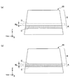
- FIG. 2 is a diagram illustrating a windshield for a vehicle
- FIG. 2 (a) is a diagram schematically showing the windshield viewed from the front of the vehicle
- FIG. 2B is a partial cross-sectional view parallel to the XZ plane of FIG.
- the HUD display area A is shown in a satin pattern.
- the windshield 20 has a HUD display area A used in HUD and a HUD display outside area B (transparent area) not used in HUD.
- the HUD display area A is located below the windshield 20, and the HUD display outside area B is located adjacent to the HUD display area A and above the HUD display area A of the windshield 20.
- C is a boundary between the HUD display area A and the HUD display outside area B.
- the windshield 20 can have a structure in which a glass plate 210 and a glass plate 220 are fixed with an intermediate film 230 sandwiched therebetween.
- the thickness of the glass plate 210 is uniform, and the thickness of the glass plate 220 is also uniform. However, the thickness of the glass plate 210 and the thickness of the glass plate 220 may not be the same.
- the inner surface 21 of the windshield 20 that is one surface of the glass plate 210 and the outer surface 22 of the windshield 20 that is one surface of the glass plate 220 may be flat or curved.
- the windshield 20 may have a shape curved in the vertical direction.
- t represents the local thickness of the windshield 20 (the total thickness of the glass plate 210, the glass plate 220, and the intermediate film 230 in that portion).
- FIG. 2B is an example of the present application, and it goes without saying that the windshield 20 may have a configuration in which a wedge-shaped glass and an intermediate film are combined.
- the intermediate film 230 is formed in a wedge shape in cross section.
- the angle formed by the surface of the intermediate film 230 that contacts the glass plate 210 and the surface of the intermediate film 230 that contacts the glass plate 220 is referred to as the wedge angle ⁇ .
- the wedge angle ⁇ can take an arbitrary value corresponding to the position in the Z direction. There may be a region where the surface of the intermediate film 230 in contact with the glass plate 210 and the surface of the intermediate film 230 in contact with the glass plate 220 are parallel. A suitable method for determining the wedge angle ⁇ will be described later. Since the thicknesses of the glass plates 210 and 220 are uniform, it can be said that the wedge angle ⁇ is an angle formed by the inner surface 21 and the outer surface 22 of the windshield 20.
- the glass plates 210 and 220 known transparent glass can be used, but general-purpose colored glass may be used for vehicles.
- a material of the glass plates 210 and 220 for example, inorganic glass, organic transparent resin glass (such as polycarbonate), or a mixture thereof can be used.
- inorganic glass a glass with a function such as a heat ray absorbing glass (green, etc.) may be used, and a glass layer may have a strengthening stress layer (by physical strengthening or chemical strengthening).
- the intermediate film 230 can be produced by, for example, extrusion molding using a known transparent resin.
- the transparent resin include polyvinyl butyral, polyvinyl alcohol, and polyethylene terephthalate.
- the intermediate film 230 may be formed by stacking a plurality of layers as necessary, or may have functional fine particles (for example, a heat shielding material such as ITO, ATO, phthalocyanine compound) in the layer. .
- a method for determining the wedge angle ⁇ that can reduce the risk of perspective distortion and foaming in the vicinity of the boundary C as compared with the prior art has been derived. That is, by applying a wedge angle ⁇ satisfying the following expression (1) at each point in a partial region of the HUD display outside region B including the edge on the boundary C side in the HUD display outside region B, the boundary C It is possible to reduce the risk of perspective distortion and foaming in the vicinity of.
- the boundary C side end in the HUD display outside region B refers to a region closest to the boundary C in the HUD display outside region B.
- the region D shows a partial region of the HUD display area outside B adjacent to the boundary C, a width of W B.
- the HUD display outside area B is illustrated in the upper part of FIG. 3A, but needless to say includes the lower part of the HUD display area A and the like.
- the region D adjacent to the boundary C in the case of close to 0 a width W B to the limit is a boundary C end of the HUD display area outside the B.
- the boundary C side end in the HUD display area A indicates an area closest to the boundary C in the HUD display area A.
- region E shows a part of a region of the HUD display area A in contact with the boundary C, a width of W A.
- the wedge angle ⁇ is, for example, at each point on the vertical line including the HUD display area A of the windshield 20 at Determined using equation (1).
- the wedge angle ⁇ may be determined using Equation (1) so as to continuously change in the horizontal direction of the windshield 20, for example.
- t is the thickness of the windshield 20
- R is the local radius of curvature of the windshield 20
- n is the refractive index of the windshield 20
- ⁇ is the ray incident on the windshield 20. It is a local incident angle.
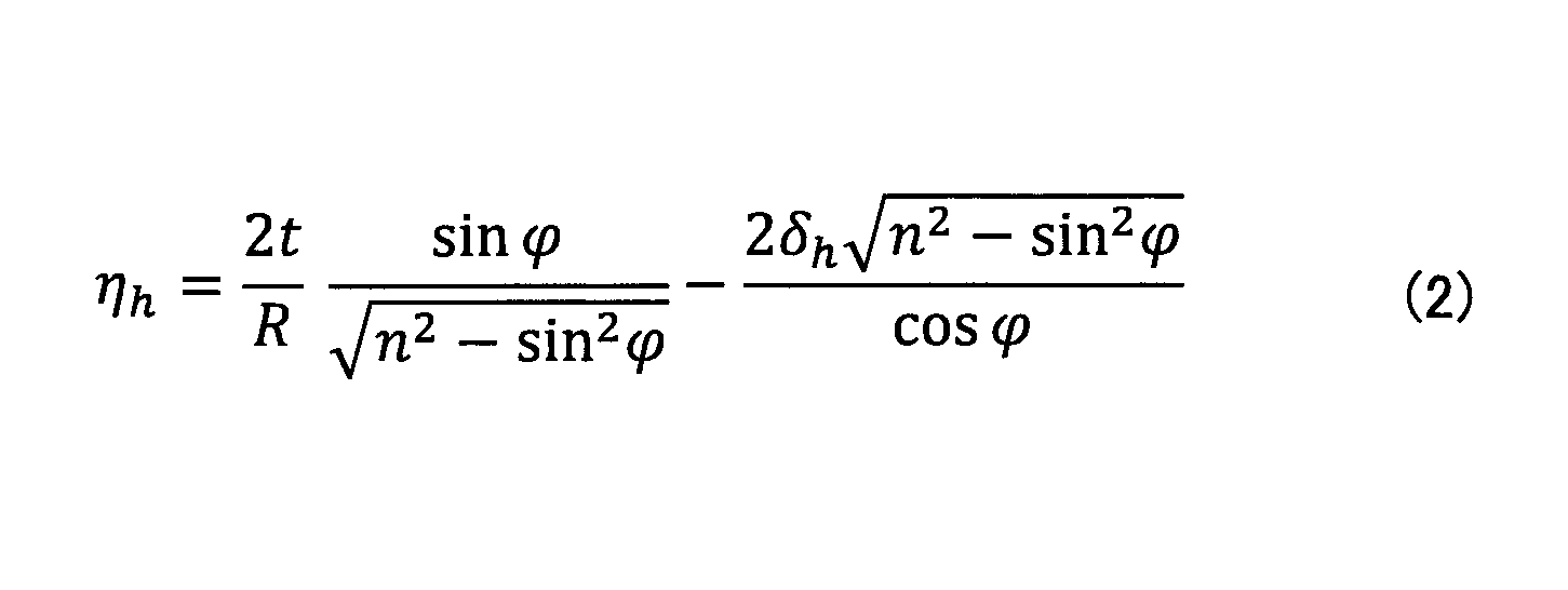
- ⁇ h is expressed by the following formula ( 2), and ⁇ is less than 2
- > 9 (however, in the HUD non-display area B) ⁇ 0 does not occur at all points in a part of the HUD display outside region B including the boundary C side end, and 0 ⁇
- the sign refers to a symbol representing a positive or negative number
- “+” is a symbol representing a positive number
- “ ⁇ ” is a symbol representing a negative number.
- “+” may be omitted.
- the angle of the perspective double image and the angle of the reflected double image when the secondary beam (dark light) is on the upper side with respect to the primary beam (bright light) (for example, FIG. 1A and FIG. 1 (b)) is defined as the “+” direction and the opposite is defined as the “ ⁇ ” direction.
- the angle of the perspective double image can be calculated according to the radius of curvature and the incident angle of the light beam according to the equation (3). Further, the wedge angle ⁇ necessary for removing the double image having the curvature radius Rc and the incident angle ⁇ can be calculated according to the equation (4).
- Formulas (1) and (2) are derived by the inventor through further studies based on Formulas (3) and (4).
- Comparative Examples 1 to 4 will be described.
- Comparative Example 1 when the wedge angle ⁇ in the HUD display area A and the wedge angle ⁇ in the HUD display outside area B are both zero (mrad) (in the HUD display area A and the HUD display outside area B, the inner surface 21 of the windshield 20). And the outer surface 22 are always parallel).
- Comparative Example 2 the wedge angle ⁇ in the HUD display area A and the wedge angle ⁇ in the HUD display outside area B are both 0.7 [mrad].
- Comparative Example 3 is a case where the wedge angle ⁇ in the HUD display area A is 0.7 [mrad] and the wedge angle ⁇ in the HUD display outside area B is zero [mrad].
- Comparative Example 4 is a case described in Patent Document 1. That is, the wedge angle ⁇ in the HUD display area A is determined based on the following formulas (5), (6), and (7), and the wedge angle ⁇ in the HUD display outside area B is expressed by the above formula (4). It is a case where it is determined based on.
- ⁇ is the tilt angle
- Ri is the distance from the windshield to the HUD light source
- ⁇ i is the incident angle of the secondary beam
- ⁇ r is the angle of the secondary beam exiting the inner surface of the glass. is there.
- ⁇ 1 is an angle between a perpendicular passing through the reflection point of the primary beam and a perpendicular passing through the point where the secondary beam passes through the glass plate
- ⁇ 2 is a perpendicular at the reflection point of the primary beam and the outer surface of the glass. The angle between the second beam and the perpendicular at the reflection point.
- ⁇ 3 is the angle between the normal at the reflection point of the primary beam and the normal at the point where the secondary beam exits the inner surface of the glass
- ⁇ i is the angle between the horizontal line and the secondary beam inside the glass plate
- ⁇ r is the angle between the horizontal line and the secondary beam inside the glass plate reflected by the outer surface of the glass.
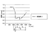
- FIG. 5A in Example 1, the change in the wedge angle at the boundary C is about 0.38 [mrad], which is larger than Comparative Examples 1 and 2, but in Comparative Examples 3 and 4. On the other hand, it can be confirmed that it has been improved.
- FIG. 5 (b) collectively shows FIGS. 4 (a), 4 (b), and 5 (a).
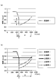
- FIG. 6 shows the angle of the reflected double image in the HUD display area A and the angle of the transparent double image in the HUD display outside area B.
- the angle of the reflected double image in the HUD display area A is minimal in Example 1, large in Comparative Example 1, small in Comparative Example 2, small in Comparative Example 3, and Comparative Example 4 Then it is minimal.
- the angle of the perspective double image in the HUD non-display area B is small in Example 1, small in Comparative Example 1, large in Comparative Example 2, small in Comparative Example 3, In Comparative Example 4, it is minimal.
- “Minimum” here means an ideal value
- “Small” means a value that can be sufficiently put into practical use
- “Large” means a value that is likely to cause a problem.
- Table 1 summarizes the results of FIGS. As shown in Table 1, the reflection double image in the HUD display area A becomes a problem in Comparative Example 1, and the perspective double image in the HUD display outside area B becomes a problem in Comparative Example 2. Further, in Comparative Examples 3 and 4, the perspective distortion at the boundary C and the risk of foaming are problematic.
- Example 1 the reflection double image in the HUD display area A, the perspective double image in the HUD display outside area B, the perspective distortion at the boundary C, and the risk of foaming can be sufficiently practically used. It can be within the range of values.
- (however, ⁇ 0 does not occur in all the points in all the regions of the HUD non-display region B including the boundary C side end in the HUD non-display region B. In addition, 0 ⁇
- the wedge angle is determined based on the formula (1) in the entire region of the HUD display outside region B.
- the perspective double image in the entire region of the HUD display outside region B, and the risk of perspective distortion and foaming at the boundary C can be made within a range of values that can sufficiently withstand practical use (minimum or small).
- the perspective double image is intentionally enlarged within a range that can be sufficiently practically used in the HUD display outside region B, and instead of the wedge angle at the boundary C, The change is suppressed, and the risk of perspective distortion and foaming at the boundary C is reduced.
- Example 1 in the HUD display area A, the wedge angle ⁇ was determined based on the equations (5) to (7) as in the case of Patent Document 1. However, the wedge angle ⁇ may be determined by other methods as long as the reflected double image in the HUD display area A is within a range of values that can sufficiently withstand practical use (minimum or small). For example, the wedge angle ⁇ in the HUD display area A can be determined by the same method as in Comparative Examples 2 and 3.
- Example 2 In the first embodiment, the example in which the expression (1) is applied to the entire area of the HUD display outside area B including the end on the boundary C side in the HUD display outside area B is shown. However, since the expression (1) is intended to suppress the change in the wedge angle at the boundary C, it is not necessarily applied to the entire area of the HUD display outside area B. Therefore, in the second embodiment, an example in which the formula (1) is applied only to a part of the HUD display outside area B including the boundary C side end in the HUD display outside area B is shown. Parts that are not particularly described are the same as those in the first embodiment.
- the wedge angle in the X direction when 400 mm ⁇ X ⁇ 490 mm is set as the HUD display area A, 490 mm ⁇ X ⁇ 1000 mm is set as the HUD display outside area B, and X 490 mm is set as the boundary C.
- the HUD display outside region B is further divided into regions B 1 and B 2 .
- the expression (1) is applied to the area B 1 of the HUD display outside area B that is in contact with the boundary C.
- the formula (1) to the region B 1 of the HUD display outside region B that is in contact with the boundary C, the change in the wedge angle at the boundary C can be suppressed, and the perspective double image in the region B 1 can be obtained.
- the size can be made within a range that can sufficiently withstand practical use.
- the wedge angle in the region B 2 may be set to an arbitrary value such that the magnitude of the range of fluoroscopic double image can withstand sufficiently practical in the region B 2, as in the region B 1 always formula (1) may not be applied.
- ⁇ 2
- (however, ⁇ at all points in a part of the HUD display outside region B including the boundary C side end in the HUD display outside region B).
- ⁇ can be an arbitrary value that satisfies ⁇ 9.0 ⁇ ⁇ ⁇ 9.0.
- is satisfied, and more preferably 0 ⁇
- the width (X direction) of the region B 1 represents may be appropriately determined according to required specifications.
- the width of the region B 1 (X direction) the width of the HUD non-display region B (X direction).
- the peripheral part of the windshield 20 is inferior to the center part (area
- the region excluding the peripheral portion of the windshield 20 is a region corresponding to the test region A defined by JIS standard R3212, for example.
Abstract
Description

実施例1では、HUD表示外領域B内の境界C側端を含むHUD表示外領域Bの全部の領域の各点において、式(1)を適用する例を示す。 <Example 1>
In the first embodiment, an example in which Expression (1) is applied to each point in the entire area of the HUD display outside area B including the end on the boundary C side in the HUD display outside area B will be described.
最初に比較例1~4について説明する。比較例1は、HUD表示領域Aにおける楔角δ、及びHUD表示外領域Bにおける楔角δが共にゼロ[mrad]の場合(HUD表示領域A及びHUD表示外領域Bにおいてフロントガラス20の内面21と外面22とが常に平行な場合)である。比較例2は、HUD表示領域Aにおける楔角δ、及びHUD表示外領域Bにおける楔角δが共に0.7[mrad]の場合である。比較例3は、HUD表示領域Aにおける楔角δが0.7[mrad]、HUD表示外領域Bにおける楔角δがゼロ[mrad]の場合である。 [Description of Example 1 and Comparative Examples 1 to 4]
First, Comparative Examples 1 to 4 will be described. In Comparative Example 1, when the wedge angle δ in the HUD display area A and the wedge angle δ in the HUD display outside area B are both zero (mrad) (in the HUD display area A and the HUD display outside area B, the

ここで、比較例1~4及び実施例1に関し、400mm≦X<490mmをHUD表示領域A、490mm<X≦1000mmをHUD表示外領域B、X=490mmを境界Cとした場合の、X方向の楔角の変化を図4及び図5に示す。なお、フロントガラス20の最も車両前方側の位置を原点(X=0)としている。 [Change in wedge angle at boundary C]
Here, regarding Comparative Examples 1 to 4 and Example 1, the X direction when 400 mm ≦ X <490 mm is the HUD display area A, 490 mm <X ≦ 1000 mm is the HUD display outside area B, and X = 490 mm is the boundary C. Changes in the wedge angle are shown in FIGS. The position of the
次に、比較例1~4及び実施例1に関し、HUD表示領域Aにおける反射二重像の角度、及び、HUD表示外領域Bにおける透視二重像の角度について、図6に示す。図6(a)に示すように、HUD表示領域Aにおける反射二重像の角度は、実施例1では極小、比較例1では大、比較例2では小、比較例3では小、比較例4では極小である。 [Angle of reflection double image, angle of perspective double image]
Next, regarding Comparative Examples 1 to 4 and Example 1, FIG. 6 shows the angle of the reflected double image in the HUD display area A and the angle of the transparent double image in the HUD display outside area B. As shown in FIG. 6A, the angle of the reflected double image in the HUD display area A is minimal in Example 1, large in Comparative Example 1, small in Comparative Example 2, small in Comparative Example 3, and Comparative Example 4 Then it is minimal.

実施例1では、HUD表示外領域B内の境界C側端を含むHUD表示外領域Bの全部の領域において、式(1)を適用する例を示した。しかし、式(1)は境界Cにおける楔角の変化を抑制することを目的としているので、必ずしも、HUD表示外領域Bの全部の領域について適用しなくてもよい。そこで、実施例2では、式(1)をHUD表示外領域B内の境界C側端を含むHUD表示外領域Bの一部の領域のみに適用する例を示す。なお、特に説明しない部分については、実施例1と同様である。 <Example 2>
In the first embodiment, the example in which the expression (1) is applied to the entire area of the HUD display outside area B including the end on the boundary C side in the HUD display outside area B is shown. However, since the expression (1) is intended to suppress the change in the wedge angle at the boundary C, it is not necessarily applied to the entire area of the HUD display outside area B. Therefore, in the second embodiment, an example in which the formula (1) is applied only to a part of the HUD display outside area B including the boundary C side end in the HUD display outside area B is shown. Parts that are not particularly described are the same as those in the first embodiment.
11a、11b、12a、12b、41a、41b、42a、42b 光線
11c、12c、41c、42c 像
20 フロントガラス
21 内面
22 外面
30 眼
210、220 ガラス板
230 中間膜
A HUD表示領域
B HUD表示外領域
C 境界
D、E 領域 10, 40
Claims (5)
- 内面と外面とを備えたガラスであって、
ヘッドアップディスプレイで使用する第1領域と、前記第1領域に隣接するヘッドアップディスプレイで使用しない第2領域と、を有し、
前記第1領域内で前記第1領域と前記第2領域との境界に最も近い領域を第1領域内境界側端、前記第2領域内で前記境界に最も近い領域を第2領域内境界側端としたときに、
前記第2領域内境界側端を含む前記第2領域の一部の領域の各点において、前記内面と前記外面とで形成する楔角δが以下の式(1)を満足することを特徴とするガラス。

前記第1領域内境界側端の楔角をδh、前記第1領域内境界側端の透視二重像の角度をηhとしたときに、ηhが以下の式(2)で表され、ηは、|ηh|≦9ならば2|ηh|もしくは9のうちの小さい方以下、|ηh|>9ならば|ηh|以下(但し、前記一部の領域の各点の全てにおいてη=0となることはなく、かつ、前記第2領域内境界側端では0<|η|である)、を満足するηhと同符号の任意の値である。
A first region used in a head-up display, and a second region not used in a head-up display adjacent to the first region,
A region closest to the boundary between the first region and the second region in the first region is a first region inner boundary side end, and a region closest to the boundary in the second region is a second region boundary side. When the end
The wedge angle δ formed by the inner surface and the outer surface satisfies the following formula (1) at each point of a partial region of the second region including the inner boundary side end of the second region. Glass to do.
When the wedge angle at the first boundary in the first region is δh and the angle of the perspective double image at the first boundary in the first region is ηh, ηh is expressed by the following equation (2), and η is , | Ηh | ≦ 9, 2 | ηh | or the smaller of 9 or less, and | ηh |> 9 if | ηh | or less (provided that η = 0 at all the points in the partial region) It is an arbitrary value having the same sign as ηh that satisfies the following condition: 0 <| η |
- 前記第2領域内境界側端を含む前記第2領域のうち、前記ガラスの周縁部を除く領域の各点において、前記内面と前記外面とで形成する楔角δが式(1)を満足することを特徴とする請求項1記載のガラス。 The wedge angle δ formed by the inner surface and the outer surface satisfies the formula (1) at each point in the region excluding the peripheral edge of the glass in the second region including the inner boundary side end of the second region. The glass according to claim 1.
- 前記第2領域内境界側端を含む前記第2領域の全部の領域の各点において、前記内面と前記外面とで形成する楔角δが式(1)を満足することを特徴とする請求項1記載のガラス。但し、式(1)において、ηは0≦|η|≦9(但し、前記全部の領域の各点の全てにおいてη=0となることはなく、かつ、前記第2領域内境界側端では0<|η|である)、を満足する任意の値である。 The wedge angle δ formed between the inner surface and the outer surface at each point in the entire region of the second region including the inner boundary side end of the second region satisfies the expression (1). 1. The glass according to 1. However, in the formula (1), η is 0 ≦ | η | ≦ 9 (however, η = 0 is not satisfied in all the points of the entire region, and at the inner boundary side end of the second region, 0 <| η |)).
- 前記第2領域内境界側端を含む前記第2領域の全部の領域の各点において、前記内面と前記外面とで形成する楔角δが式(1)を満足することを特徴とする請求項1記載のガラス。但し、式(1)において、ηは0≦|η|≦6(但し、前記全部の領域の各点の全てにおいてη=0となることはなく、かつ、前記第2領域内境界側端では0<|η|である)、を満足する任意の値である。 The wedge angle δ formed between the inner surface and the outer surface at each point in the entire region of the second region including the inner boundary side end of the second region satisfies the expression (1). 1. The glass according to 1. However, in the formula (1), η is 0 ≦ | η | ≦ 6 (however, η = 0 is not satisfied in all the points of the entire region, and at the inner boundary side end of the second region, 0 <| η |)).
- 前記第2領域内境界側端を含む前記第2領域の全部の領域の各点において、前記内面と前記外面とで形成する楔角δが式(1)を満足することを特徴とする請求項1記載のガラス。但し、式(1)において、ηは0≦|η|≦3(但し、前記全部の領域の各点の全てにおいてη=0となることはなく、かつ、前記第2領域内境界側端では0<|η|である)、を満足する任意の値である。 The wedge angle δ formed between the inner surface and the outer surface at each point in the entire region of the second region including the inner boundary side end of the second region satisfies the expression (1). 1. The glass according to 1. However, in the formula (1), η is 0 ≦ | η | ≦ 3 (however, η = 0 does not occur in all the points of the entire region, and at the inner boundary side end of the second region, 0 <| η |)).
Priority Applications (4)
| Application Number | Priority Date | Filing Date | Title |
|---|---|---|---|
| EP15827689.9A EP3176015B1 (en) | 2014-07-30 | 2015-07-27 | Glass |
| CN201580039973.9A CN106573527B (en) | 2014-07-30 | 2015-07-27 | Glass |
| JP2016538330A JP6432600B2 (en) | 2014-07-30 | 2015-07-27 | Glass |
| US15/343,832 US10946622B2 (en) | 2014-07-30 | 2016-11-04 | Glass |
Applications Claiming Priority (4)
| Application Number | Priority Date | Filing Date | Title |
|---|---|---|---|
| JP2014-155188 | 2014-07-30 | ||
| JP2014155188 | 2014-07-30 | ||
| JP2015-087068 | 2015-04-21 | ||
| JP2015087068 | 2015-04-21 |
Related Child Applications (1)
| Application Number | Title | Priority Date | Filing Date |
|---|---|---|---|
| US15/343,832 Continuation US10946622B2 (en) | 2014-07-30 | 2016-11-04 | Glass |
Publications (1)
| Publication Number | Publication Date |
|---|---|
| WO2016017566A1 true WO2016017566A1 (en) | 2016-02-04 |
Family
ID=55217467
Family Applications (1)
| Application Number | Title | Priority Date | Filing Date |
|---|---|---|---|
| PCT/JP2015/071199 WO2016017566A1 (en) | 2014-07-30 | 2015-07-27 | Glass |
Country Status (5)
| Country | Link |
|---|---|
| US (1) | US10946622B2 (en) |
| EP (1) | EP3176015B1 (en) |
| JP (1) | JP6432600B2 (en) |
| CN (1) | CN106573527B (en) |
| WO (1) | WO2016017566A1 (en) |
Cited By (9)
| Publication number | Priority date | Publication date | Assignee | Title |
|---|---|---|---|---|
| WO2017078160A1 (en) * | 2015-11-05 | 2017-05-11 | 積水化学工業株式会社 | Interlayer for laminated glass and laminated glass |
| WO2017175639A1 (en) * | 2016-04-07 | 2017-10-12 | 旭硝子株式会社 | Laminated glass |
| EP3269547A1 (en) * | 2016-07-15 | 2018-01-17 | Asahi Glass Company, Limited | Laminated glass |
| JP2019038745A (en) * | 2017-03-30 | 2019-03-14 | 積水化学工業株式会社 | Interlayer for glass laminate and glass laminate |
| WO2019093085A1 (en) * | 2017-11-07 | 2019-05-16 | パナソニックIpマネジメント株式会社 | Headup display |
| EP3381879A4 (en) * | 2015-11-24 | 2019-08-21 | AGC Inc. | Laminated glass |
| JP2020073423A (en) * | 2017-03-30 | 2020-05-14 | 積水化学工業株式会社 | Interlayer film for laminated glass, and laminated glass |
| US10967610B2 (en) * | 2017-10-30 | 2021-04-06 | AGC Inc. | Laminated glass |
| US11774750B2 (en) | 2017-05-23 | 2023-10-03 | AGC Inc. | Laminated glass |
Families Citing this family (6)
| Publication number | Priority date | Publication date | Assignee | Title |
|---|---|---|---|---|
| JP6569898B2 (en) * | 2015-06-30 | 2019-09-04 | パナソニックIpマネジメント株式会社 | Display device and display method |
| JP6769876B2 (en) * | 2015-09-30 | 2020-10-14 | 積水化学工業株式会社 | Laminated glass interlayer film and laminated glass |
| RU2019134199A (en) * | 2017-03-28 | 2021-04-28 | Секисуй Кемикал Ко., Лтд. | INTERMEDIATE FILM FOR LAMINATED GLASS, ROLL AND LAMINATED GLASS |
| CN109626848B (en) * | 2017-10-05 | 2022-12-20 | Agc株式会社 | Laminated glass |
| US11481889B2 (en) * | 2019-04-03 | 2022-10-25 | Pittsburgh Glass Works, Llc | Fixture for evaluating heads-up windshields |
| CN110341834A (en) * | 2019-08-13 | 2019-10-18 | 杭州炽云科技有限公司 | A method of windshield of the optimization for head-up-display system imaging |
Citations (1)
| Publication number | Priority date | Publication date | Assignee | Title |
|---|---|---|---|---|
| JP5315358B2 (en) * | 2007-12-07 | 2013-10-16 | サン−ゴバン グラス フランス | Curved vehicle windshield made of laminated glass |
Family Cites Families (16)
| Publication number | Priority date | Publication date | Assignee | Title |
|---|---|---|---|---|
| JPS5315358B2 (en) | 1972-08-31 | 1978-05-24 | ||
| JPS61169713U (en) * | 1985-04-09 | 1986-10-21 | ||
| US5812332A (en) | 1989-09-28 | 1998-09-22 | Ppg Industries, Inc. | Windshield for head-up display system |
| US5013134A (en) * | 1989-09-28 | 1991-05-07 | Hughes Aircraft Company | Ghost-free automotive head-up display employing a wedged windshield |
| JPH0899561A (en) * | 1994-09-30 | 1996-04-16 | Asahi Glass Co Ltd | Head up display |
| WO1999063389A1 (en) * | 1998-06-03 | 1999-12-09 | Nippon Sheet Glass Co., Ltd. | Head-up display device and laminated glass for head-up display device |
| JP2007223883A (en) * | 2005-12-26 | 2007-09-06 | Asahi Glass Co Ltd | Laminated glass for vehicle |
| CN102515572B (en) * | 2006-05-12 | 2015-02-04 | 积水化学工业株式会社 | Intermediate film for laminated glass and laminated glass |
| DE102007059323A1 (en) * | 2007-12-07 | 2009-06-10 | Saint-Gobain Sekurit Deutschland Gmbh & Co. Kg | Curved windscreen for motor vehicle, has outer and inner glass surfaces with wedge angle that is changed from lower edge upto upper edge of field of vision to compensate double images in each point on vertical center line of field of vision |
| WO2009100576A1 (en) * | 2008-02-04 | 2009-08-20 | Industrial Technology Research Institute | Display system |
| GB0817654D0 (en) * | 2008-09-26 | 2008-11-05 | Pilkington Automotive Deutschland Gmbh | Laminated glazing |
| EP2918563B1 (en) * | 2010-09-01 | 2017-12-13 | Sekisui Chemical Co., Ltd. | Interlayer film for laminated glass, and laminated glass |
| KR101868250B1 (en) * | 2013-12-12 | 2018-07-17 | 쌩-고벵 글래스 프랑스 | Thermoplastic film for a laminated-glass pane having a non-linear continuous wedge insert in the vertical and horizontal direction in some sections |
| CN103792662B (en) * | 2014-01-15 | 2016-08-17 | 深圳点石创新科技有限公司 | A kind of anti-ghost head-up display |
| US20160168353A1 (en) * | 2014-12-08 | 2016-06-16 | Solutia Inc. | Interlayers having enhanced optical properties |
| US9975315B2 (en) * | 2014-12-08 | 2018-05-22 | Solutia Inc. | Poly(vinyl acetal) resin compositions, layers, and interlayers having enhanced optical properties |
-
2015
- 2015-07-27 CN CN201580039973.9A patent/CN106573527B/en active Active
- 2015-07-27 JP JP2016538330A patent/JP6432600B2/en active Active
- 2015-07-27 WO PCT/JP2015/071199 patent/WO2016017566A1/en active Application Filing
- 2015-07-27 EP EP15827689.9A patent/EP3176015B1/en active Active
-
2016
- 2016-11-04 US US15/343,832 patent/US10946622B2/en active Active
Patent Citations (1)
| Publication number | Priority date | Publication date | Assignee | Title |
|---|---|---|---|---|
| JP5315358B2 (en) * | 2007-12-07 | 2013-10-16 | サン−ゴバン グラス フランス | Curved vehicle windshield made of laminated glass |
Cited By (16)
| Publication number | Priority date | Publication date | Assignee | Title |
|---|---|---|---|---|
| WO2017078160A1 (en) * | 2015-11-05 | 2017-05-11 | 積水化学工業株式会社 | Interlayer for laminated glass and laminated glass |
| JPWO2017078160A1 (en) * | 2015-11-05 | 2018-08-16 | 積水化学工業株式会社 | Laminated glass interlayer film and laminated glass |
| US10996468B2 (en) | 2015-11-24 | 2021-05-04 | AGC Inc. | Laminated glass |
| EP3381879A4 (en) * | 2015-11-24 | 2019-08-21 | AGC Inc. | Laminated glass |
| WO2017175639A1 (en) * | 2016-04-07 | 2017-10-12 | 旭硝子株式会社 | Laminated glass |
| JPWO2017175639A1 (en) * | 2016-04-07 | 2019-03-07 | Agc株式会社 | Laminated glass |
| US10353200B2 (en) | 2016-07-15 | 2019-07-16 | AGC Inc. | Laminated glass |
| JP2018008862A (en) * | 2016-07-15 | 2018-01-18 | 旭硝子株式会社 | Laminated glass |
| EP3269547A1 (en) * | 2016-07-15 | 2018-01-17 | Asahi Glass Company, Limited | Laminated glass |
| JP2019038745A (en) * | 2017-03-30 | 2019-03-14 | 積水化学工業株式会社 | Interlayer for glass laminate and glass laminate |
| JP2020073423A (en) * | 2017-03-30 | 2020-05-14 | 積水化学工業株式会社 | Interlayer film for laminated glass, and laminated glass |
| US11433650B2 (en) | 2017-03-30 | 2022-09-06 | Sekisui Chemical Co., Ltd. | Intermediate film for laminated glasses, and laminated glass |
| US11774750B2 (en) | 2017-05-23 | 2023-10-03 | AGC Inc. | Laminated glass |
| US10967610B2 (en) * | 2017-10-30 | 2021-04-06 | AGC Inc. | Laminated glass |
| WO2019093085A1 (en) * | 2017-11-07 | 2019-05-16 | パナソニックIpマネジメント株式会社 | Headup display |
| JPWO2019093085A1 (en) * | 2017-11-07 | 2019-11-14 | パナソニックIpマネジメント株式会社 | Head-up display |
Also Published As
| Publication number | Publication date |
|---|---|
| JPWO2016017566A1 (en) | 2017-04-27 |
| US10946622B2 (en) | 2021-03-16 |
| EP3176015A1 (en) | 2017-06-07 |
| CN106573527A (en) | 2017-04-19 |
| EP3176015B1 (en) | 2019-04-03 |
| EP3176015A4 (en) | 2018-04-04 |
| JP6432600B2 (en) | 2018-12-05 |
| US20170072663A1 (en) | 2017-03-16 |
| CN106573527B (en) | 2019-01-25 |
Similar Documents
| Publication | Publication Date | Title |
|---|---|---|
| JP6432600B2 (en) | Glass | |
| US10495877B2 (en) | Free-form surface lens and head-up display | |
| JP6780652B2 (en) | Laminated glass | |
| US10175480B2 (en) | Head up display device that prevents ghosting and vehicle | |
| EP3441375B1 (en) | Laminated glass | |
| US11774756B2 (en) | Head-up display | |
| US20180312044A1 (en) | Laminated glass | |
| US20160252739A1 (en) | Stereoscopic display device | |
| WO2016038767A1 (en) | Head up display and moving body | |
| WO2019093085A1 (en) | Headup display | |
| DE102018103476B4 (en) | WINDSCREEN DISPLAY SYSTEM AND DEVICE WITH A WINDSCREEN DISPLAY SYSTEM | |
| EP3677949B1 (en) | Display apparatus and display method | |
| WO2018116778A1 (en) | Virtual image display device | |
| JP6183413B2 (en) | Display device | |
| JP7145430B2 (en) | Head-up displays and moving objects with head-up displays | |
| CN113858730B (en) | Laminated glass and head-up display system | |
| US9778472B2 (en) | Stereoscopic display device | |
| US10466393B2 (en) | Display device | |
| CN107407811B (en) | Head-up display | |
| JPWO2019012919A1 (en) | Laminated glass for vehicle front windows | |
| US20170153452A1 (en) | Reflecting plate for display, optical system for projecting display light and method of producing windshield | |
| JP2019152795A (en) | Head-up display device | |
| US11287650B2 (en) | Head-up display and mobile object comprising head-up display including a display panel, a barrier, and an optical system configured to focus image light corresponding to a parallax image | |
| TWI629509B (en) | Display device with ordinary windshield and automobile head-up display system using the same | |
| JP2016002975A (en) | Auxiliary device for blind area |
Legal Events
| Date | Code | Title | Description |
|---|---|---|---|
| 121 | Ep: the epo has been informed by wipo that ep was designated in this application |
Ref document number: 15827689 Country of ref document: EP Kind code of ref document: A1 |
|
| ENP | Entry into the national phase |
Ref document number: 2016538330 Country of ref document: JP Kind code of ref document: A |
|
| REEP | Request for entry into the european phase |
Ref document number: 2015827689 Country of ref document: EP |
|
| WWE | Wipo information: entry into national phase |
Ref document number: 2015827689 Country of ref document: EP |
|
| NENP | Non-entry into the national phase |
Ref country code: DE |