WO2016017356A1 - User terminal, wireless base station, and wireless communication method - Google Patents
User terminal, wireless base station, and wireless communication method Download PDFInfo
- Publication number
- WO2016017356A1 WO2016017356A1 PCT/JP2015/068992 JP2015068992W WO2016017356A1 WO 2016017356 A1 WO2016017356 A1 WO 2016017356A1 JP 2015068992 W JP2015068992 W JP 2015068992W WO 2016017356 A1 WO2016017356 A1 WO 2016017356A1
- Authority
- WO
- WIPO (PCT)
- Prior art keywords
- pusch
- user terminal
- transmission
- uplink
- control
- Prior art date
Links
Images


Classifications
-
- H—ELECTRICITY
- H04—ELECTRIC COMMUNICATION TECHNIQUE
- H04L—TRANSMISSION OF DIGITAL INFORMATION, e.g. TELEGRAPHIC COMMUNICATION
- H04L1/00—Arrangements for detecting or preventing errors in the information received
- H04L1/12—Arrangements for detecting or preventing errors in the information received by using return channel
- H04L1/16—Arrangements for detecting or preventing errors in the information received by using return channel in which the return channel carries supervisory signals, e.g. repetition request signals
- H04L1/18—Automatic repetition systems, e.g. Van Duuren systems
- H04L1/1829—Arrangements specially adapted for the receiver end
- H04L1/1854—Scheduling and prioritising arrangements
-
- H—ELECTRICITY
- H04—ELECTRIC COMMUNICATION TECHNIQUE
- H04W—WIRELESS COMMUNICATION NETWORKS
- H04W72/00—Local resource management
- H04W72/50—Allocation or scheduling criteria for wireless resources
- H04W72/54—Allocation or scheduling criteria for wireless resources based on quality criteria
- H04W72/542—Allocation or scheduling criteria for wireless resources based on quality criteria using measured or perceived quality
-
- H—ELECTRICITY
- H04—ELECTRIC COMMUNICATION TECHNIQUE
- H04L—TRANSMISSION OF DIGITAL INFORMATION, e.g. TELEGRAPHIC COMMUNICATION
- H04L1/00—Arrangements for detecting or preventing errors in the information received
- H04L1/12—Arrangements for detecting or preventing errors in the information received by using return channel
- H04L1/16—Arrangements for detecting or preventing errors in the information received by using return channel in which the return channel carries supervisory signals, e.g. repetition request signals
- H04L1/18—Automatic repetition systems, e.g. Van Duuren systems
- H04L1/1867—Arrangements specially adapted for the transmitter end
- H04L1/1893—Physical mapping arrangements
-
- H—ELECTRICITY
- H04—ELECTRIC COMMUNICATION TECHNIQUE
- H04L—TRANSMISSION OF DIGITAL INFORMATION, e.g. TELEGRAPHIC COMMUNICATION
- H04L5/00—Arrangements affording multiple use of the transmission path
- H04L5/003—Arrangements for allocating sub-channels of the transmission path
- H04L5/0053—Allocation of signaling, i.e. of overhead other than pilot signals
- H04L5/0055—Physical resource allocation for ACK/NACK
-
- H—ELECTRICITY
- H04—ELECTRIC COMMUNICATION TECHNIQUE
- H04L—TRANSMISSION OF DIGITAL INFORMATION, e.g. TELEGRAPHIC COMMUNICATION
- H04L5/00—Arrangements affording multiple use of the transmission path
- H04L5/14—Two-way operation using the same type of signal, i.e. duplex
-
- H—ELECTRICITY
- H04—ELECTRIC COMMUNICATION TECHNIQUE
- H04W—WIRELESS COMMUNICATION NETWORKS
- H04W28/00—Network traffic management; Network resource management
- H04W28/02—Traffic management, e.g. flow control or congestion control
- H04W28/04—Error control
-
- H—ELECTRICITY
- H04—ELECTRIC COMMUNICATION TECHNIQUE
- H04W—WIRELESS COMMUNICATION NETWORKS
- H04W72/00—Local resource management
- H04W72/04—Wireless resource allocation
-
- H—ELECTRICITY
- H04—ELECTRIC COMMUNICATION TECHNIQUE
- H04W—WIRELESS COMMUNICATION NETWORKS
- H04W72/00—Local resource management
- H04W72/04—Wireless resource allocation
- H04W72/044—Wireless resource allocation based on the type of the allocated resource
- H04W72/0446—Resources in time domain, e.g. slots or frames
-
- H—ELECTRICITY
- H04—ELECTRIC COMMUNICATION TECHNIQUE
- H04W—WIRELESS COMMUNICATION NETWORKS
- H04W72/00—Local resource management
- H04W72/20—Control channels or signalling for resource management
- H04W72/21—Control channels or signalling for resource management in the uplink direction of a wireless link, i.e. towards the network
-
- H—ELECTRICITY
- H04—ELECTRIC COMMUNICATION TECHNIQUE
- H04W—WIRELESS COMMUNICATION NETWORKS
- H04W72/00—Local resource management
- H04W72/20—Control channels or signalling for resource management
- H04W72/23—Control channels or signalling for resource management in the downlink direction of a wireless link, i.e. towards a terminal
Definitions
- the present invention relates to a user terminal, a radio base station, and a radio communication method applicable to a next generation communication system.
- LTE Long Term Evolution
- SC-FDMA Single Carrier Frequency Division Multiple Access
- LTE-A LTE Advanced or LTE enhancement
- Frequency division duplex that divides uplink (UL) and downlink (DL) by frequency as duplex format (Duplex-mode) in radio communication of LTE and LTE-A systems, and uplink and downlink Is divided by time (TDD) (see FIGS. 1A and 1B).
- FDD Frequency division duplex
- Duplex-mode duplex format
- TDD uplink and downlink Is divided by time
- a plurality of frame configurations (UL / DL configuration (UL / DL configuration)) with different transmission ratios between uplink subframes (UL subframes) and downlink subframes (DL subframes) are defined.
- UL subframes uplink subframes
- DL subframes downlink subframes
- FIG. 2 seven frame configurations of UL / DL configurations 0 to 6 are defined, subframes # 0 and # 5 are allocated to the downlink, and subframe # 2 is the uplink. Assigned to the link.
- the system band of the LTE-A system includes at least one component carrier (CC: Component Carrier) having the system band of the LTE system as a unit. Collecting a plurality of component carriers (cells) to increase the bandwidth is called carrier aggregation (CA).
- CC Component Carrier
- the DL traffic volume and the UL traffic volume are different, and it is assumed that the DL traffic volume is larger than the UL traffic volume. Further, the ratio between the DL traffic volume and the UL traffic volume is not constant and varies with time or place.
- the present invention has been made in view of the above points, and provides a radio base station, a user terminal, and a radio communication method capable of flexibly controlling UL transmission and DL transmission to improve throughput and communication quality in radio communication.
- One purpose is to provide.
- An aspect of the user terminal includes a transmitter that transmits uplink data using an uplink shared channel, a receiver that receives downlink control information and downlink data transmitted from a radio base station, and a received downlink data
- a control unit that controls transmission of an acknowledgment signal, wherein the receiving unit receives downlink data (DL-PUSCH) transmitted using an uplink shared channel, and the control unit is configured for DL-PUSCH. Control is performed to transmit a delivery confirmation signal at a predetermined timing.
- UL transmission and DL transmission can be flexibly controlled to improve the throughput and communication quality in wireless communication.
- the frequency resource for UL cannot be used for DL communication in FDD, and the time resource for UL cannot be dynamically used for DL communication in TDD. Effective utilization of resources has become difficult.
- the TDD UL time resource is changed to the DL time by changing the TDD UL / DL configuration to semi-static for each cell.
- Utilization as a resource (eIMTA) is being studied.
- the radio base station selects the UL / DL configuration (for example, UL / DL configurations 4, 5 and the like in FIG. 2 above) having a high DL subframe ratio according to the communication environment of the own cell. Resources can be secured.
- the present inventors have focused on the fact that communication using the PUSCH format (D2D discovery / communication) is supported between user terminals in D2D (Device to Device) communication. That is, a user terminal that supports D2D communication has a function of receiving a signal (SC-FDMA signal) transmitted in the same format (PUSCH format) as PUSCH using UL resources.
- the user terminal performs D2D discovery (D2D discovery) for finding other user terminals that can communicate.
- D2D discovery the network allocates a periodic uplink resource (PUSCH) to each user terminal semi-statically as a D2D discovery resource.
- the user terminal allocates a discovery signal (discovery signal) to the D2D discovery resource and transmits it. Further, the user terminal can find another user terminal capable of communication by receiving the discovery signal transmitted from the other user terminal.
- PUSCH periodic uplink resource
- discovery signal discovery signal
- D2D communication it is considered to perform communication between user terminals using PUSCH resources.
- the present inventors have focused on the fact that a predetermined UL resource is not always required between a radio base station and a user terminal when application of carrier aggregation (CA) is supported.
- CA carrier aggregation
- a radio base station performs DL communication in a PUSCH format using a UL resource (for example, PUSCH). That is, the radio base station assigns and transmits downlink data to the uplink shared channel (PUSCH) set in the UL subframe of the TDD cell and / or PUSCH set to the UL frequency of FDD.
- the user terminal performs reception processing on downlink data assigned to PUSCH.
- a downlink signal (for example, downlink data) transmitted from the radio base station using PUSCH is also referred to as DL-PUSCH (or DL-PUSCH signal).
- FIG. 3 shows an example in which DL communication is performed using UL resources.
- FIG. 3A shows a case where DL communication is performed using some UL resources (subframes # 2, # 3, # 6, and # 7) of FDD. That is, in some UL resources, a DL signal (DL-PUSCH) is transmitted from the radio base station to the user terminal using PUSCH. In other subframes, the user terminal transmits a UL signal using PUSCH as in the existing subframe.
- DL-PUSCH DL signal
- FIG. 3B shows a case where DL communication is performed using some UL resources (here, UL subframes # 2 and # 3) of TDD. That is, in some UL subframes of TDD, a DL signal (DL-PUSCH) is transmitted from the radio base station to the user terminal using PUSCH. In other subframes (here, UL subframes # 7 and # 8), the user terminal transmits a UL signal using PUSCH as in the existing LTE / LTE-A system.
- FIG. 3B shows the TDD UL / DL configuration 1, the present embodiment is not limited to this.
- the user terminal can be configured to notify the network in advance that it has the ability to receive DL-PUSCH (PUSCH reception capability).
- the radio base station can selectively transmit the DL-PUSCH to a predetermined user terminal.
- the PUSCH reception capability is defined as the capability of the user terminal, the radio base station can receive DL-PUSCH in an arbitrary frequency band when receiving a notification that the PUSCH reception capability has the PUSCH reception capability. Can be considered.
- the PUSCH reception capability may be defined as the capability of the user terminal in a specific frequency band. In this case, the user terminal notifies the radio base station whether or not it has PUSCH reception capability in each frequency band in which it can communicate.
- the radio base station can be configured to perform DL-PUSCH reception in a frequency band in which the user terminal has PUSCH reception capability.
- the radio base station configures PUSCH reception in the UL resource for the user terminal.
- the radio base station uses higher layer signaling (RRC signaling, broadcast signal, etc.) to notify the user terminal of information for setting (enable / disable) DL-PUSCH reception and information necessary for DL-PUSCH reception.
- RRC signaling radio resource control
- broadcast signal etc.
- the radio base station can dynamically transmit information related to the DL-PUSCH reception instruction.
- the user terminal confirms the presence / absence of a DL-PUSCH reception instruction and controls the operation according to the presence / absence of an instruction from the radio base station.
- the user terminal performs reception processing (demodulation, etc.) on the DL-PUSCH received from the radio base station using UL resources (UL frequency in FDD, UL subframe in TDD), and then transmits data from the physical layer to the higher layer. I can pass.
- UL resources can be dynamically used for DL communication in units of 1 ms corresponding to transmission time intervals (for example, subframes). Furthermore, by applying in combination with CA, it is possible to flexibly and dynamically use the UL frequency in FDD or TDD for DL communication.
- a radio base station that performs DL-PUSCH transmission is a user terminal that performs UL transmission of PUSCH using UL resources or a user that performs D2D communication in physically or frequency adjacent cells. It can be regarded as equivalent to a terminal.
- the reference signal (UL DM-RS) included in PUSCH is randomized (or whitened) by making the reference signal sequence and scramble code different between adjacent cells physically or in frequency. Can do. Therefore, by using PUSCH for DL communication using UL resources, even when collision with PUSCH transmitted by a user terminal in a physical or frequency neighboring cell occurs, interference randomization (or white) Therefore, deterioration due to interference can be minimized.
- Hybrid ARQ retransmission control
- the user terminal transmits an acknowledgment signal (HARQ-ACK) for the downlink shared channel (PDSCH) through the uplink control channel (PUCCH) and / or the uplink shared channel (PUSCH).
- HARQ-ACK acknowledgment signal
- the user terminal modulates HARQ-ACK with a predetermined method and feeds it back in a predetermined subframe after PDSCH reception.
- L1 / L2 control signals such as downlink control channels (PDCCH and / or EPDCCH) and / or (2) higher layer signaling such as RRC.
- the radio base station transmits a DL-PUSCH reception instruction (for example, also referred to as a DL-PUSCH grant) to the user terminal using a downlink control channel or higher layer signaling.
- a delivery confirmation signal for the DL-PUSCH received by the user terminal is transmitted at a predetermined timing.
- the user terminal feeds back a predetermined period (xms) after receiving the DL-PUSCH, or receives a downlink control channel (DL-PUSCH grant) indicating the DL-PUSCH for a predetermined period (xms).
- DL-PUSCH grant downlink control channel
- UL transmission and DL transmission can be flexibly controlled, thereby improving throughput and communication quality in wireless communication. Can be improved.
- carrier aggregation (CA) or dual connectivity (DC) can be applied between a cell to which DL-PUSCH transmission / reception is applied and a cell to which DL-PUSCH transmission / reception is not applied.
- CA carrier aggregation
- DC dual connectivity
- the CA can be applied with a cell that does not perform DL-PUSCH transmission / reception as a primary cell (PCell) and a cell that performs DL-PUSCH transmission / reception as a secondary cell (SCell).
- PCell primary cell
- SCell secondary cell
- CA refers to integrating a plurality of component carriers (also referred to as CCs, carriers, cells, etc.) to increase the bandwidth.
- CC component carriers
- Each CC has, for example, a maximum bandwidth of 20 MHz, and a maximum bandwidth of 100 MHz is realized when a maximum of five CCs are integrated.
- a scheduler of one radio base station controls scheduling of a plurality of CCs. From this, CA may be called CA in a base station (intra-eNB CA).
- Dual connectivity is the same as CA in that a plurality of CCs are integrated to increase the bandwidth.
- a plurality of schedulers are provided independently, and the plurality of schedulers control the scheduling of one or more cells (CC) under their jurisdiction. From this, DC may be called CA between base stations (inter-eNB CA).
- inter-eNB CA base stations
- carrier aggregation intra-eNB CA
- a user terminal transmits a Hybrid ARQ at a predetermined timing after receiving a DL-PUSCH transmitted from a radio base station.
- a predetermined timing (1) a value specified in a reference UL / DL configuration (DL reference UL-DL configuration), (2) a predetermined value (for example, 4 ms), or (3) TDD-FDD CA (TDD It can be determined based on the HARQ-ACK timing defined by (PCell).
- the timings (1) to (3) will be described below.
- the following (1) and (2) assume TDD and (3) assume FDD DL-PUSCH transmission / reception, but the present invention is not limited to this.
- the user terminal that receives the DL-PUSCH can transmit HARQ-ACK for the received DL-PUSCH at a timing defined by the reference UL / DL configuration (DL reference UL-DL configuration) (see FIG. 4).
- the reference UL / DL configuration refers to a UL / DL configuration used for HARQ timing.
- the user terminal uses the table in which HARQ timing is defined based on the UL / DL configuration (base UL / DL configuration) set for data transmission and the reference UL / DL configuration, and uses the HARQ- of DL-PUSCH.
- ACK transmission timing can be controlled.
- the user terminal can use the HARQ timing defined in eIMTA as a reference UL / DL configuration.
- a UL / DL configuration (reference UL / DL configuration) used for HARQ timing is set separately from the TDD UL / DL configuration (base UL / DL configuration) set in the user terminal.
- TDD UL / DL configuration base UL / DL configuration
- FIG. 5 shows the HARQ timing of the existing TDD
- FIG. 6 shows the HARQ timing applicable in this embodiment.
- FIG. 5A is a table showing HARQ timing in TDD of the existing system (LTE).
- a DL subframe that feeds back HARQ-ACK is associated with each UL subframe of each UL / DL configuration.
- the user terminal in subframe # 2 (UL subframe), performs HARQ for PDSCH transmitted in DL subframes 6, 7, and 11 subframes before the subframe.
- -ACK is transmitted (see FIG. 5B).
- FIG. 6A is a table in which HARQ timings in the UL / DL configuration 3 in FIG. 5A are extracted.
- FIG. 6B is a table showing HARQ timing when the reference UL / DL configuration is used.
- a base UL / DL configuration used by the user terminal and a reference UL / DL configuration (2, 4, 5) are defined for the base UL / DL configuration.
- the user terminal selects the subframes 6, 7, and 11 subframes before the UL subframe # 2 as subframes that feed back HARQ-ACK in the UL subframe # 2 as in the existing system ( (See FIG. 6A). Further, in the UL subframe # 2, the user terminal selects a subframe that is 13, 12, 5, 4, 8, and 9 subframes before the UL subframe # 2 (see FIG. 6B).
- the user terminal uses the subframe # 2 in consideration of the base UL / DL configuration and the reference UL / DL configuration, and 4, 5, 6, 7, 8, 9, 11, 12 from the subframe.
- HARQ-ACK for the subframe 13 subframes before is transmitted (see FIG. 6C).
- FIG. 6C shows HARQ timing based on the reference UL / DL configuration.
- Information on the base UL / DL configuration and / or the reference UL / DL configuration is notified from the radio base station to the user terminal.
- the user terminal controls the HARQ timing of the received downlink data (PDSCH, DL-PUSCH) based on the base UL / DL configuration notified from the radio base station and the reference UL / DL configuration.
- the HARQ timing (table) defined in the reference UL / DL configuration of eIMTA can be used, whereas eIMTA receives DL data on PDSCH (see FIG. 7A).
- the present embodiment is different in that DL data is received by PUSCH (see FIG. 7B).
- the radio base station notifies the user terminal of the UL / DL configuration (base UL / DL configuration) to be applied in the TDD cell.
- FIG. 7B shows a case where the base UL / DL configuration 3 is notified.
- broadcast signal or higher layer signaling such as RRC signaling can be applied.
- the radio base station notifies / configures DL-PUSCH reception and reference UL / DL configuration to the user terminal.
- FIG. 7B shows a case where the reference UL / DL configuration 5 is notified.
- broadcast signals or higher layer signaling such as RRC signaling, MAC control elements, physical control signals, and the like can be applied.
- the radio base station instructs the user terminal to which DL-PUSCH is set to receive DL-PUSCH in a predetermined subframe.
- FIG. 7B shows a case where subframes # 3 and # 4 are indicated as DL-PUSCH reception subframes.
- broadcast signals or higher layer signaling such as RRC signaling, MAC control elements, physical control signals, and the like can be applied.
- the user terminal performs a DL-PUSCH reception operation in a specified predetermined subframe, and transmits the result (HARQ-ACK) at a predetermined timing.
- the radio base station When receiving the ACK from the user terminal, the radio base station performs the next data transmission assuming that the transmitted DL-PUSCH is successfully received by the user terminal. On the other hand, when the NACK is received from the user terminal, the DL-PUSCH retransmits the downlink data on the assumption that the user terminal receives a reception error.
- DL communication since DL-PUSCH is performed using PUSCH (PUSCH format), the signal configuration is the same as UL communication (UL-PUSCH) of user terminals in other cells.
- DL transmission using PUSCH is configured with data (DL-PUSCH) and a reference signal (DM-RS) for demodulating the data, similar to UL transmission using PUSCH.
- DM-RS reference signal
- DL-PUSCH DL communication using PUSCH
- CRS cell-specific reference signal
- CSI-RS channel state measurement signal
- the radio base station lowers the transmission power compared to DL subframe (for example, user terminal DL-PUSCH can be transmitted with a maximum transmission power of. Thereby, the interference given to UL communication of an adjacent cell or an adjacent frequency can be reduced.
- the PUSCH is a single carrier-based signal, the PAPR is small and the power utilization efficiency is high, so that it is possible to save power in the radio base station.
- the user terminal can transmit HARQ-ACK for the received DL-PUSCH after a predetermined period. For example, the user terminal transmits HARQ-ACK 4 ms after receiving DL-PUSCH.
- the user terminal adopts a configuration for performing communication with a carrier in which UL transmission is continuously maintained, for example, an FDD cell having a UL frequency and carrier aggregation (CA) or dual connectivity (DC) ( (See FIG. 9).
- FIG. 9 shows a case where CC # 1 to which TDD is applied and CC # 0 to which FDD is applied apply CA.
- the FDD cell can be a PCell or a PSCell that allows PUCCH allocation (transmission).
- the user terminal feeds back HARQ-ACK corresponding to the DL-PUSCH using the FDD UL subframe 4 ms after the DL-PUSCH received subframe.
- the user terminal receives the DL-PUSCH based on the information (DL-PUSCH setting, DL-PUSCH reception instruction) notified from the radio base station, as in (1) Reference UL / DL configuration. Controls HARQ-ACK transmission.
- the user terminal can control the HARQ timing based on the HARQ timing (table) defined for FDD serving as SCell in TDD-FDD CA using TDD as PCell.
- HARQ-ACK for PDSCH transmitted in FDD DL may be transmitted in TDD UL subframe serving as PCell.
- the user terminal controls the HARQ timing of the HARQ-ACK using the reference UL / DL configuration. Therefore, when the UL subframe is used for DL-PUSCH, HARQ-ACK feedback can be controlled based on the reference UL / DL configuration.
- a case is assumed in which UL-PDSCH is transmitted in FDD that does not apply CA.
- a user terminal may transmit HARQ-ACK for PDSCH received in a DL subframe using a UL subframe after a predetermined period (for example, 4 ms). it can.
- HARQ timing based on the reference UL / DL configuration selected in consideration of the DL-PUSCH transmission / reception subframe is applied in the UL frequency.
- the HARQ timing defined for FDD-SCell is applied when TDD-FDD CA is TDD-PCell.
- a UL / DL configuration corresponding to the reference UL / DL configuration set in the UL frequency can be applied.
- FIG. 10A shows a table defining the HARQ timing of the FDD serving as the SCell in TDD-FDD CA (TDD is PCell).
- FIG. 10B illustrates the HARQ timing of an FDD (SCell) that performs CA with a TDD cell to which the TDD UL / DL configuration 3 is applied as a PCell. As shown in FIG. 10B, HARQ-ACK corresponding to each DL subframe of the FDD cell is transmitted in a predetermined UL subframe of TDD.
- FIG. 11 shows an example of HARQ timing when a part of the UL subframe of FDD is used for transmission of UL-PDSCH.
- the HARQ timing of the reference UL / DL configuration 3 is applied to the UL frequency of the FDD, and the HARQ timing when the TDD that becomes the PCell in the TDD-FDD CA becomes the UL / DL configuration 3 is applied to the DL frequency.
- the reference UL / DL configuration applied to the UL frequency may be a UL / DL configuration corresponding to a case where a subframe in which DL-PUSCH transmission is performed is assumed to be DL.
- Information regarding part or all of the HARQ timing applied by the user terminal may be notified from the radio base station to the user terminal, or may be determined by the user terminal based on a subframe in which DL-PUSCH reception is performed. Good.
- the information regarding part or all of the HARQ timing includes information regarding the UL / DL configuration applied to the UL frequency of the FDD, information regarding the reference UL / DL configuration applied to the DL frequency of the FDD, and the like.
- the user terminal may define the HARQ timing for the DL frequency in accordance with the UL / DL configuration set to the UL frequency of the FDD.
- the user terminal feeds back HARQ-ACK for DL-PUSCH at a timing after a predetermined period (xms) after receiving downlink control information (PDCCH / EPDCCH) indicating the DL-PUSCH.
- a predetermined period xms
- PDCCH downlink control information
- the user terminal determines whether or not the DL-PUSCH received in a predetermined UL subframe is successfully received based on an instruction from the radio base station, and a predetermined period has elapsed since then.
- HARQ-ACK is fed back in a subsequent (for example, after 4 ms) subframe.
- the user terminal when the user terminal detects downlink control information (PDCCH / EPDCCH) received in a predetermined DL subframe, the user terminal determines whether or not the DL-PUSCH has been received at a predetermined timing after detection.
- HARQ-ACK is fed back in a subframe after a predetermined period has elapsed since the detection of the downlink control information (for example, after 4 ms).
- the control signal instructing DL reception and the DL data signal are multiplexed in the same subframe.
- the control signal and the data signal are not necessarily multiplexed in the same subframe, and the timing at which the data signal is transmitted / received is delayed with respect to the timing at which the control signal is transmitted / received (a predetermined subframe). This is likely to be done after a frame).
- the HARQ timing of the DL-PUSCH is controlled, and preparation for HARQ transmission is started when the control signal is detected. Therefore, the round trip delay of HARQ can be shortened, and the user experience communication speed can be improved.
- the user terminal can control the feedback of the DL-PUSCH delivery confirmation signal (HARQ-ACK) at a predetermined timing.
- HARQ-ACK DL-PUSCH delivery confirmation signal
- radio resources determined implicitly based on a downlink control channel instructing DL-PUSCH reception, (2) instructing DL-PUSCH reception Radio resources that are explicitly indicated in the downlink control channel to be set, (3) radio resources that are implicitly determined by DL-PUSCH, or (4) upper layer signaling (RRC signaling, etc.) It is conceivable to use radio resources and the like.
- a PUCCH resource assigned to a UL resource can be used as a radio resource to which a DL-PUSCH is assigned.
- a user terminal can select a PUCCH resource based on a resource number of a downlink control channel (PDCCH and / or EPDCCH) instructing DL-PUSCH reception. For example, the user terminal transmits HARQ-ACK using a PUCCH resource determined based on a CCE index / ECCE index constituting a PDCCH / EPDCCH instructing reception of DL-PUSCH.
- a downlink control channel (PDCCH and / or EPDCCH) instructing DL-PUSCH reception.
- a grant (for example, UL grant) instructing DL-PUSCH reception and a PUCCH resource correspond to Implicit (see FIG. 12).
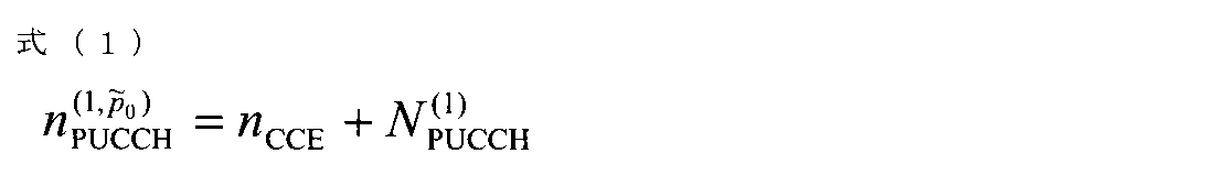
- the PUCCH resource is determined using the CCE index (n CCE ) constituting the PUCCH. For example, it can be determined using the following equation (1).
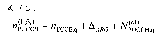
- the PUCCH resource is determined using the ECCE index (n ECCE ) constituting the EPUCCH. For example, it can be determined using the following equation (2).
- a predetermined CCE index (CCE index having the smallest number) can be used.
- Such a method reuses a method of determining a PUCCH resource by a PDCCH / EPDCCH resource number including a DL assignment in the existing LTE.
- Implicit information used for selecting the PUCCH resource in addition to the resource number, the PDCCH / EPDCCH antenna port number, the mapping position of the reference signal, the PDCCH / EPDCCH or the parameter corresponding to the scramble cell ID (virtual) A cell ID (Virtual Cell ID)) may be included.
- the circuit configuration of the user terminal is simplified and easily implemented by using the PUCCH assignment method for DL assignment (DL assignment) instructing PDSCH reception for HARQ-ACK transmission of DL-PUSCH. Can do.
- PUCCH resource determined to be Explicit by downlink control channel A bit area for specifying a PUCCH resource may be introduced into the downlink control channel (PDCCH / EPDCCH).
- the user terminal can determine the PUCCH resource based on information indicated in the bit area. That is, the PUCCH resource is instructed to be explicit by a grant (for example, UL grant) instructing DL-PUSCH reception (see FIG. 13A).
- a plurality of PUCCH resources can be set in advance, and a predetermined PUCCH resource can be instructed to the user terminal.
- the radio base station notifies / sets a plurality of PUCCH resources (1 st to 4 th PUCCH resource value) to the user terminal in advance using higher layer signaling such as RRC (see FIG. 13B).
- the radio base station dynamically indicates to the user terminal which PUCCH resource to transmit the HARQ-ACK by using a PUCCH resource indicator bit (PUCCH resource indicator) included in the downlink control channel (see FIG. 13B).
- PUCCH resource indicator PUCCH resource indicator
- a bit (bit area) indicating a predetermined PUCCH resource may be newly added to downlink control information (DCI format), or an existing bit area may be used as a bit for indicating a PUCCH resource. Is possible.
- the user terminal can select a PUCCH resource for transmitting HARQ-ACK based on the received information about the DL-PUSCH resource and the like.
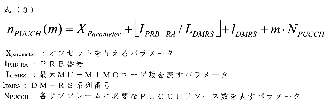
- DL-PUSCH allocation resource block (PRB) number and / or DM-RS sequence number, etc. can be used as information on DL-PUSCH resources. That is, the received DL-PUSCH and PUCCH resources correspond to Implicit (FIG. 14).
- the DL-PUSCH PRB is duplicated only between MU-MIMO (Multi User-MIMO) user terminals.
- MU-MIMO Multi User-MIMO
- the PRB number is duplicated even if the PRB number is duplicated.
- the user terminal when allocating DL-PUSCH HARQ-ACK to the PUCCH resource of the m-th subframe, the user terminal can control PUCCH resource allocation using the following equation (3).
- N_PUCCH the number of PUCCH resources
- HARQ-ACK for DL-PUSCH transmitted in subframe # 8 and subframe # 9 is fed back in the same UL subframe.
- the user terminal has different offsets (offset is 0). PUCCH collision can be avoided by adding (including cases).
- the subframe number shown in FIG. 15 corresponds to the subframe number in the case of going back with reference to the UL subframe that feeds back HARQ-ACK.
- FIG. 16 is a schematic configuration diagram illustrating an example of a wireless communication system according to an embodiment of the present invention.
- the radio communication system 1 is in a cell formed by a plurality of radio base stations 10 (11 and 12) and each radio base station 10, and is configured to be able to communicate with each radio base station 10.
- Each of the radio base stations 10 is connected to the higher station apparatus 30 and connected to the core network 40 via the higher station apparatus 30.
- the radio base station 11 is composed of, for example, a macro base station having a relatively wide coverage, and forms a macro cell C1.
- the radio base station 12 is configured by a small base station having local coverage, and forms a small cell C2.
- the number of radio base stations 11 and 12 is not limited to the number shown in FIG.
- the same frequency band may be used, or different frequency bands may be used.
- the radio base stations 11 and 12 are connected to each other via an inter-base station interface (for example, optical fiber, X2 interface).
- the macro base station 11 may be referred to as a radio base station, an eNodeB (eNB), a transmission point, or the like.
- the small base station 12 may be called a pico base station, a femto base station, a Home eNodeB (HeNB), a transmission point, an RRH (Remote Radio Head), or the like.
- the user terminal 20 is a terminal that supports various communication methods such as LTE and LTE-A, and may include not only a mobile communication terminal but also a fixed communication terminal.
- the user terminal 20 can execute communication with other user terminals 20 via the radio base station 10.
- the upper station apparatus 30 includes, for example, an access gateway apparatus, a radio network controller (RNC), a mobility management entity (MME), and the like, but is not limited thereto.
- RNC radio network controller
- MME mobility management entity
- OFDMA Orthogonal Frequency Division Multiple Access
- SC-FDMA Single Carrier Frequency Division Multiple Access
- OFDMA is a multi-carrier transmission scheme that performs communication by dividing a frequency band into a plurality of narrow frequency bands (subcarriers) and mapping data to each subcarrier.
- SC-FDMA is a single-carrier transmission scheme that reduces interference between terminals by dividing the system bandwidth into bands consisting of one or continuous resource blocks for each terminal and using a plurality of terminals with mutually different bands. is there.
- the uplink and downlink radio access methods are not limited to these combinations.
- downlink channels include a downlink shared channel (PDSCH) shared by each user terminal 20, a broadcast channel (PBCH: Physical Broadcast Channel), a downlink L1 / L2 control channel, and the like. Used. User data, higher layer control information, and predetermined SIB (System Information Block) are transmitted by PDSCH. Also, a synchronization signal, MIB (Master Information Block), etc. are transmitted by PBCH.
- PDSCH downlink shared channel
- PBCH Physical Broadcast Channel
- SIB System Information Block
- Downlink L1 / L2 control channels include PDCCH (Physical Downlink Control Channel), EPDCCH (Enhanced Physical Downlink Control Channel), PCFICH (Physical Control Format Indicator Channel), PHICH (Physical Hybrid-ARQ Indicator Channel), and the like.
- Downlink control information (DCI: Downlink Control Information) including scheduling information of PDSCH and PUSCH is transmitted by PDCCH.
- the number of OFDM symbols used for PDCCH is transmitted by PCFICH.
- the PHICH transmits a HARQ delivery confirmation signal (ACK / NACK) to the PUSCH.
- the EPDCCH is frequency division multiplexed with a PDSCH (downlink shared data channel) and may be used to transmit DCI or the like in the same manner as the PDCCH.
- an uplink shared channel (PUSCH: Physical Uplink Shared Channel), an uplink control channel (PUCCH: Physical Uplink Control Channel), and a random access channel (PRACH) shared by each user terminal 20 are used. Physical Random Access Channel) is used.
- PUSCH Physical Uplink Shared Channel
- PUCCH Physical Uplink Control Channel
- PRACH random access channel
- User data and higher layer control information are transmitted by PUSCH.
- DL transmission (DL-PUSCH transmission / reception) is performed using PUSCH set to a predetermined UL resource (UL subframe or UL frequency band).
- downlink radio quality information CQI: Channel Quality Indicator
- HARQ-ACK delivery confirmation signal
- An acknowledgment signal for DL-PUSCH can also be transmitted using PUCCH.
- a random access preamble (RA preamble) for establishing a connection with the cell is transmitted by the PRACH.
- a channel quality measurement reference signal SRS: Sounding Reference Signal
- DM-RS Demodulation Reference Signal
- FIG. 17 is an overall configuration diagram of the radio base station 10 according to the present embodiment.
- the radio base station 10 (including the radio base stations 11 and 12) includes a plurality of transmission / reception antennas 101 for MIMO transmission, an amplifier unit 102, a transmission / reception unit 103, a baseband signal processing unit 104, and a call processing unit 105. And a transmission path interface 106.
- the transmission / reception unit 103 includes a transmission unit and a reception unit.
- User data transmitted from the radio base station 10 to the user terminal 20 via the downlink is input from the higher station apparatus 30 to the baseband signal processing unit 104 via the transmission path interface 106.
- PDCP Packet Data Convergence Protocol
- RLC Radio Link Control
- MAC Medium Access
- Retransmission control for example, HARQ (Hybrid Automatic Repeat reQuest) transmission processing
- HARQ Hybrid Automatic Repeat reQuest
- the downlink control signal is also subjected to transmission processing such as channel coding and inverse fast Fourier transform, and transferred to each transmitting / receiving unit 103.
- Each transmitting / receiving unit 103 converts the downlink signal output from the baseband signal processing unit 104 by precoding for each antenna into a radio frequency band and transmits the converted signal.
- the radio frequency signal frequency-converted by the transmission / reception unit 103 is amplified by the amplifier unit 102 and transmitted from the transmission / reception antenna 101.
- the transmission / reception unit 103 transmits information (enable / disable) for setting reception of downlink data (DL-PUSCH) using the uplink shared channel (PUSCH) to the user terminal in higher layer signaling (RRC, broadcast signal). Etc.). Further, the transmission / reception unit 103 can notify the user terminal of information on subframes for transmitting / receiving DL-PUSCH.
- the transmitter / receiver 103 can employ a transmitter / receiver, a transmitter / receiver circuit, or a transmitter / receiver used in the technical field according to the present invention.
- the radio frequency signal received by each transmitting / receiving antenna 101 is amplified by the amplifier unit 102.
- Each transmitting / receiving unit 103 receives the upstream signal amplified by the amplifier unit 102.
- the transmission / reception unit 103 converts the frequency of the received signal into a baseband signal and outputs it to the baseband signal processing unit 104.
- the transceiver 103 receives a DL-PUSCH delivery confirmation signal fed back from the user terminal at a predetermined timing.
- the baseband signal processing unit 104 performs fast Fourier transform (FFT) processing, inverse discrete Fourier transform (IDFT: Inverse Discrete Fourier Transform) processing, and error correction on user data included in the input upstream signal.
- FFT fast Fourier transform
- IDFT inverse discrete Fourier transform
- Decoding, MAC retransmission control reception processing, RLC layer, and PDCP layer reception processing are performed and transferred to the upper station apparatus 30 via the transmission path interface 106.
- the call processing unit 105 performs call processing such as communication channel setting and release, state management of the radio base station 10, and radio resource management.
- the transmission path interface 106 transmits and receives signals to and from the higher station apparatus 30 via a predetermined interface. Further, the transmission path interface 106 may transmit / receive a signal (backhaul signaling) to / from an adjacent radio base station via an interface between base stations (for example, an optical fiber or an X2 interface).
- a signal backhaul signaling
- FIG. 18 is a main functional configuration diagram of the baseband signal processing unit 104 included in the radio base station 10 according to the present embodiment. Note that FIG. 18 mainly shows functional blocks of characteristic portions in the present embodiment, and the wireless base station 10 also has other functional blocks necessary for wireless communication.
- the radio base station 10 includes at least a control unit (scheduler) 301, a transmission signal generation unit 302, a mapping unit 303, and a reception processing unit 304.
- the control unit (scheduler) 301 controls scheduling of downlink data transmitted on the PDSCH, downlink control signals transmitted on the PDCCH and / or extended PDCCH (EPDCCH) (transmission from the radio base station 10).
- the control unit 301 also controls scheduling of downlink data (DL-PUSCH) transmitted on the PUSCH.
- the control unit 301 also controls scheduling of system information, synchronization signals, downlink reference signals such as CRS and CSI-RS, and the like. In addition, the control unit 301 controls scheduling (transmission from the user terminal 20) of uplink reference signals, uplink data transmitted on the PUSCH, uplink control signals transmitted on the PUCCH and / or PUSCH, and the like.
- the control unit 301 can be configured with a controller, a control circuit, or a control device used in the technical field according to the present invention.
- control unit 301 can instruct the user terminal to receive DL-PUSCH using the downlink control channel (PDCCH and / or EPDCCH). For example, the control unit 301 transmits a DL-PUSCH in a subframe in which an uplink data transmission instruction by UL grant is not performed. In addition, the control unit 301 performs control so that DL-PUSCH is transmitted in the same subframe as the subframe instructing the DL-PUSCH grant or a subframe after a predetermined period.
- PDCCH and / or EPDCCH downlink control channel
- the control unit 301 transmits a DL-PUSCH in a subframe in which an uplink data transmission instruction by UL grant is not performed.
- control unit 301 performs control so that DL-PUSCH is transmitted in the same subframe as the subframe instructing the DL-PUSCH grant or a subframe after a predetermined period.
- control unit 301 sets a grant that instructs transmission of uplink data using PUSCH (for example, a UL grant of an existing system) and a grant that instructs reception of DL-PUSCH as one grant. May be used.
- the user terminal 20 can determine the content of the UL grant based on other information (such as subframe information in which DL-PUSCH is transmitted).
- the transmission signal generation unit 302 generates a DL signal (downlink control signal, downlink data, downlink reference signal, etc.) based on an instruction from the control unit 301 and outputs the DL signal to the mapping unit 303. For example, based on an instruction from the control unit 301, the transmission signal generation unit 302 generates a DL assignment (DL assignment) for notifying downlink signal allocation information and a UL grant (UL grant) for notifying uplink signal allocation information. Generate. Also, the downlink data is subjected to coding processing and modulation processing according to the coding rate, modulation scheme, and the like determined based on CSI from each user terminal 20 and the like.
- the transmission signal generation unit 302 generates downlink data in the PUSCH format in a predetermined UL subframe. Downlink data (DL-PUSCH) generated in the PUSCH format is mapped to an uplink resource (PUSCH) by the mapping unit 303.
- the transmission signal generation unit 302 can be configured by a signal generator or a signal generation circuit used in the technical field according to the present invention.
- the mapping unit 303 maps the downlink signal generated by the transmission signal generation unit 302 to a radio resource based on an instruction from the control unit 301, and outputs the radio signal to the transmission / reception unit 103.
- the mapping unit 303 maps downlink data to PDSCH or PUSCH based on an instruction from the control unit 301.
- the mapping unit 303 can be configured by a mapping circuit or mapper used in the technical field according to the present invention.
- the reception processing unit 304 performs reception processing (for example, demapping, demodulation, decoding, etc.) on the UL signal (uplink control signal, uplink data, uplink reference signal, etc.) transmitted from the user terminal 20. Further, the reception processing unit 304 may measure the received power (RSRP) and the channel state using the received signal (for example, SRS). The processing result and the measurement result may be output to the control unit 301.
- the reception processing unit 304 can be configured by a signal processor or a signal processing circuit used in the technical field according to the present invention.
- FIG. 19 is an overall configuration diagram of the user terminal 20 according to the present embodiment.
- the user terminal 20 includes a plurality of transmission / reception antennas 201 for MIMO transmission, an amplifier unit 202, a transmission / reception unit 203, a baseband signal processing unit 204, and an application unit 205.
- the transmission / reception unit 203 may include a transmission unit and a reception unit.
- the radio frequency signals received by the plurality of transmission / reception antennas 201 are each amplified by the amplifier unit 202.
- Each transmitting / receiving unit 203 receives the downlink signal amplified by the amplifier unit 202.
- the transmission / reception unit 203 converts the frequency of the received signal into a baseband signal and outputs it to the baseband signal processing unit 204.
- the transmission / reception unit 203 receives the DL-PUSCH based on information for setting (enable / disable) DL-PUSCH reception. Further, the transmission / reception unit 203 (reception unit) transmits a delivery confirmation signal to the received DL-PUSCH.
- the transmission / reception unit 203 can be configured by a transmitter / receiver, a transmission / reception circuit, or a transmission / reception device used in the technical field according to the present invention.
- the baseband signal processing unit 204 performs FFT processing, error correction decoding, retransmission control reception processing, and the like on the input baseband signal.
- the downlink user data is transferred to the application unit 205.
- the application unit 205 performs processing related to layers higher than the physical layer and the MAC layer.
- broadcast information in the downlink data is also transferred to the application unit 205.
- uplink user data is input from the application unit 205 to the baseband signal processing unit 204.
- the baseband signal processing unit 204 performs retransmission control transmission processing (for example, HARQ transmission processing), channel coding, precoding, discrete Fourier transform (DFT) processing, IFFT processing, and the like.
- the data is transferred to the transmission / reception unit 203.
- the transmission / reception unit 203 converts the baseband signal output from the baseband signal processing unit 204 into a radio frequency band and transmits it.
- the radio frequency signal frequency-converted by the transmission / reception unit 203 is amplified by the amplifier unit 202 and transmitted from the transmission / reception antenna 201.
- FIG. 20 is a main functional configuration diagram of the baseband signal processing unit 204 included in the user terminal 20. Note that FIG. 20 mainly shows functional blocks of characteristic portions in the present embodiment, and the user terminal 20 also has other functional blocks necessary for wireless communication.
- the user terminal 20 includes at least a control unit 401, a transmission signal generation unit 402, a mapping unit 403, a reception processing unit 404, and a determination unit 405.
- the reception processing unit 404 performs reception processing (for example, demapping, demodulation, decoding, etc.) on the DL signal transmitted from the radio base station 10. Also, the reception processing unit 404 can perform reception processing of DL-PUSCH transmitted using PUSCH based on information on subframes to which DL-PUSCH transmission / reception is applied.
- the reception processing unit 404 can be configured by a signal processor or a signal processing circuit used in the technical field according to the present invention.
- the reception processing unit 404 decodes a downlink control signal transmitted through the downlink control channel (PDCCH / EPDCCH), and outputs scheduling information to the control unit 401. Also, the reception processing unit 404 decodes downlink data transmitted on the downlink shared channel (PDSCH) and downlink data transmitted on the uplink shared channel (PUSCH), and outputs the decoded data to the determination unit 405. Further, the reception processing unit 404 may measure the received power (RSRP) and the channel state using the received signal. The processing result and the measurement result may be output to the control unit 401.
- RSRP received power
- the determination unit 405 performs retransmission control determination (ACK / NACK) based on the decoding result of the reception processing unit 404 and outputs the result to the control unit 401.
- the retransmission control determination can be performed on downlink data transmitted on the PDSCH and downlink data (DL-PUSCH) transmitted on the PUSCH.
- the control unit 401 generates / generates UL signals such as uplink control signals (feedback signals) and uplink data based on downlink control signals transmitted from the radio base stations and retransmission control determination results for PDSCH and / or DL-PUSCH. Control transmission. Specifically, the control unit 401 controls the transmission signal generation unit 402 and the mapping unit 403. The downlink control signal is output from the reception processing unit 404, and the retransmission control determination result is output from the determination unit 405.
- the control unit 401 can be configured by a controller, a control circuit, or a control device used in the technical field according to the present invention.
- the control unit 401 controls to transmit a delivery confirmation signal for the DL-PUSCH at a predetermined timing. For example, the control unit 401, based on the timing of receiving a DL-PUSCH or the timing of receiving a downlink control channel (DL-PUSCH grant) instructing reception of the DL-PUSCH, Control transmission.
- DL-PUSCH grant downlink control channel
- control unit 401 confirms the delivery to the DL-PUSCH based on a table in which the transmission timing of the delivery confirmation signal is defined corresponding to the base UL / DL configuration and the reference UL / DL configuration. Signal transmission can be controlled (see FIGS. 6B and 7B). Alternatively, the control unit 401 can control transmission of a delivery confirmation signal to the DL-PUSCH after a certain period of time has elapsed from the timing of receiving the DL-PUSCH or the timing of receiving the DL-PUSCH grant.
- control unit 401 when the control unit 401 receives the DL-PUSCH allocated to the UL resource of the FDD cell, the control unit 401 performs DL based on the table in which the transmission timing of the delivery confirmation signal is defined corresponding to the reference UL / DL configuration. -The transmission of the delivery confirmation signal to the PUSCH can be controlled (see FIG. 10A and FIG. 11).
- control unit 401 allocates a delivery confirmation signal corresponding to the DL-PUSCH to a predetermined uplink control channel resource based on a downlink control channel (for example, a CCE index or the like) instructing reception of the DL-PUSCH.
- the mapping unit 403 can be instructed.
- control unit 401 instructs the mapping unit 403 to allocate a delivery confirmation signal corresponding to the DL-PUSCH to a predetermined uplink control channel resource based on the received DL-PUSCH information (for example, PRB number). Can be directed.
- the transmission signal generation unit 402 generates a UL signal based on an instruction from the control unit 401 and outputs the UL signal to the mapping unit 403. For example, the transmission signal generation unit 402 generates an uplink control signal such as a delivery confirmation signal (HARQ-ACK) or channel state information (CSI) based on an instruction from the control unit 401.
- HARQ-ACK delivery confirmation signal
- CSI channel state information
- the transmission signal generation unit 402 generates uplink data based on an instruction from the control unit 401. For example, when the UL grant is included in the downlink control signal notified from the radio base station 10, the control unit 401 instructs the transmission signal generation unit 402 to generate uplink data.
- the transmission signal generation unit 402 can be configured by a signal generator or a signal generation circuit used in the technical field according to the present invention.
- the mapping unit 403 maps the uplink signal generated by the transmission signal generation unit 402 to a radio resource (for example, PUCCH or PUSCH), and outputs the radio signal to the transmission / reception unit 203.
- a radio resource for example, PUCCH or PUSCH
- the mapping unit 403 maps a delivery confirmation signal for DL-PUSCH to a predetermined PUCCH resource.
- the mapping unit 403 can be configured with a mapping circuit or mapper used in the technical field according to the present invention.
- each functional block may be realized by one physically coupled device, or may be realized by two or more physically separated devices connected by wire or wirelessly and by a plurality of these devices. Good.
- radio base station 10 and the user terminal 20 are realized using hardware such as ASIC (Application Specific Integrated Circuit), PLD (Programmable Logic Device), and FPGA (Field Programmable Gate Array). May be.
- the radio base station 10 and the user terminal 20 may be realized by a computer apparatus including a processor (CPU), a communication interface for network connection, a memory, and a computer-readable storage medium holding a program. Good.
- the processor and memory are connected by a bus for communicating information.
- the computer-readable recording medium is a storage medium such as a flexible disk, a magneto-optical disk, a ROM, an EPROM, a CD-ROM, a RAM, and a hard disk.
- the program may be transmitted from a network via a telecommunication line.
- the radio base station 10 and the user terminal 20 may include an input device such as an input key and an output device such as a display.
- the functional configurations of the radio base station 10 and the user terminal 20 may be realized by the hardware described above, may be realized by a software module executed by a processor, or may be realized by a combination of both.
- the processor controls the entire user terminal by operating an operating system. Further, the processor reads programs, software modules and data from the storage medium into the memory, and executes various processes according to these.
- the program may be a program that causes a computer to execute the operations described in the above embodiments.
- the control unit 401 of the user terminal 20 may be realized by a control program stored in a memory and operated by a processor, and may be realized similarly for other functional blocks.
Abstract
Description
第1の態様では、ユーザ端末が無線基地局から送信されるDL-PUSCHを受信してから所定タイミングでHybrid ARQを送信する場合について説明する。所定タイミングとしては、(1)参照用UL/DL構成(DL reference UL-DL configuration)で規定された値、(2)所定値(例えば、4ms)、又は(3)TDD-FDD CA(TDDがPCell)で規定されたHARQ-ACKのタイミング、に基づいて決定することができる。以下に、各タイミング(1)~(3)について説明する。なお、以下の(1)、(2)はTDD、(3)はFDDのDL-PUSCH送受信を想定しているがこれに限られない。 (First aspect)
In the first aspect, a case will be described in which a user terminal transmits a Hybrid ARQ at a predetermined timing after receiving a DL-PUSCH transmitted from a radio base station. As the predetermined timing, (1) a value specified in a reference UL / DL configuration (DL reference UL-DL configuration), (2) a predetermined value (for example, 4 ms), or (3) TDD-FDD CA (TDD It can be determined based on the HARQ-ACK timing defined by (PCell). The timings (1) to (3) will be described below. The following (1) and (2) assume TDD and (3) assume FDD DL-PUSCH transmission / reception, but the present invention is not limited to this.
DL-PUSCHを受信するユーザ端末は、受信したDL-PUSCHに対するHARQ-ACKを参照用UL/DL構成(DL reference UL-DL configuration)で規定されたタイミングで送信することができる(図4参照)。参照用UL/DL構成とは、HARQタイミング用に利用されるUL/DL構成を指す。例えば、ユーザ端末は、データ送信に設定されるUL/DL構成(ベースUL/DL構成)と参照用UL/DL構成に基づいてHARQタイミングが規定されたテーブルを用いて、DL-PUSCHのHARQ-ACKの送信タイミングを制御することができる。 (1) Hybrid ARQ based on UL / DL configuration for reference
The user terminal that receives the DL-PUSCH can transmit HARQ-ACK for the received DL-PUSCH at a timing defined by the reference UL / DL configuration (DL reference UL-DL configuration) (see FIG. 4). . The reference UL / DL configuration refers to a UL / DL configuration used for HARQ timing. For example, the user terminal uses the table in which HARQ timing is defined based on the UL / DL configuration (base UL / DL configuration) set for data transmission and the reference UL / DL configuration, and uses the HARQ- of DL-PUSCH. ACK transmission timing can be controlled.
ユーザ端末は、DL-PUSCH受信を行う場合、受信したDL-PUSCHに対するHARQ-ACKを所定期間経過後に送信することができる。例えば、ユーザ端末は、DL-PUSCHを受信してから4ms後にHARQ-ACKを送信する。 (2) Hybrid ARQ based on predetermined values
When receiving the DL-PUSCH, the user terminal can transmit HARQ-ACK for the received DL-PUSCH after a predetermined period. For example, the user terminal transmits HARQ-
ユーザ端末は、DL-PUSCH受信を行う場合、TDDをPCellとするTDD-FDD CAにおいて、SCellとなるFDD用に規定されたHARQタイミング(テーブル)に基づいてHARQタイミングを制御することができる。 (3) Hybrid ARQ in TDD-FDD CA
When receiving the DL-PUSCH, the user terminal can control the HARQ timing based on the HARQ timing (table) defined for FDD serving as SCell in TDD-FDD CA using TDD as PCell.
第2の態様では、ユーザ端末が、DL-PUSCH受信を指示する下り制御情報(DL-PUSCH用グラント)に基づいてHARQタイミングを制御する場合について説明する。 (Second aspect)
In the second mode, a case will be described in which the user terminal controls HARQ timing based on downlink control information (DL-PUSCH grant) instructing DL-PUSCH reception.
上記第1の態様、第2の態様で示したように、ユーザ端末は、DL-PUSCHの送達確認信号(HARQ-ACK)のフィードバックを所定のタイミングで制御することができる。一方で、DL-PUSCHのHARQ-ACKの送信に利用するULリソース(例えば、HARQ-ACKを割当てるHARQリソース)を決定する必要がある。そこで、第3の態様では、DL-PUSCHのHARQ-ACKを無線リソースへ割当てる方法について説明する。 (Third aspect)
As shown in the first aspect and the second aspect, the user terminal can control the feedback of the DL-PUSCH delivery confirmation signal (HARQ-ACK) at a predetermined timing. On the other hand, it is necessary to determine a UL resource (for example, a HARQ resource to which HARQ-ACK is allocated) used for transmission of DL-PUSCH HARQ-ACK. Therefore, in the third aspect, a method for allocating DL-PUSCH HARQ-ACK to radio resources will be described.
ユーザ端末は、DL-PUSCH受信を指示する下り制御チャネル(PDCCH及び/又はEPDCCH)のリソース番号に基づいてPUCCHリソースを選択することができる。例えば、ユーザ端末は、DL-PUSCH受信を指示するPDCCH/EPDCCHを構成するCCEインデックス/ECCEインデックスに基づいて定まるPUCCHリソースでHARQ-ACKを送信する。 (1) PUCCH resource determined Implicit by downlink control channel A user terminal can select a PUCCH resource based on a resource number of a downlink control channel (PDCCH and / or EPDCCH) instructing DL-PUSCH reception. For example, the user terminal transmits HARQ-ACK using a PUCCH resource determined based on a CCE index / ECCE index constituting a PDCCH / EPDCCH instructing reception of DL-PUSCH.
下り制御チャネル(PDCCH/EPDCCH)に、PUCCHリソースを指定するビット領域を導入してもよい。ユーザ端末は、当該ビット領域で指示される情報に基づいてPUCCHリソースを決定することができる。つまり、DL-PUSCH受信を指示するグラント(例えば、ULグラント)でPUCCHリソースをExplicitに指示する(図13A参照)。 (2) PUCCH resource determined to be Explicit by downlink control channel A bit area for specifying a PUCCH resource may be introduced into the downlink control channel (PDCCH / EPDCCH). The user terminal can determine the PUCCH resource based on information indicated in the bit area. That is, the PUCCH resource is instructed to be explicit by a grant (for example, UL grant) instructing DL-PUSCH reception (see FIG. 13A).
ユーザ端末は、受信したDL-PUSCHのリソースに関する情報等に基づいてHARQ-ACKを送信するPUCCHリソースを選択することができる。 (3) PUCCH resource determined as Implicit by DL-PUSCH The user terminal can select a PUCCH resource for transmitting HARQ-ACK based on the received information about the DL-PUSCH resource and the like.
以下、本発明の一実施の形態に係る無線通信システムの構成について説明する。この無線通信システムでは、上記第1の態様~第3の態様のいずれか又はこれらの組み合わせが適用される。 (Configuration of wireless communication system)
Hereinafter, a configuration of a wireless communication system according to an embodiment of the present invention will be described. In this wireless communication system, any one of the first to third aspects or a combination thereof is applied.
Claims (10)
- 上り共有チャネルを用いて上りデータを送信する送信部と、
無線基地局から送信される下り制御情報及び下りデータを受信する受信部と、
受信した下りデータに対する送達確認信号の送信を制御する制御部と、を有し、
前記受信部は、上り共有チャネルを用いて送信される下りデータ(DL-PUSCH)を受信し、前記制御部は、DL-PUSCHに対する送達確認信号を所定タイミングで送信するように制御することを特徴とするユーザ端末。 A transmitter that transmits uplink data using an uplink shared channel;
A receiving unit for receiving downlink control information and downlink data transmitted from the radio base station;
A control unit for controlling transmission of a delivery confirmation signal for the received downlink data,
The reception unit receives downlink data (DL-PUSCH) transmitted using an uplink shared channel, and the control unit controls to transmit a delivery confirmation signal for the DL-PUSCH at a predetermined timing. User terminal. - 前記制御部は、DL-PUSCHを受信したタイミングに基づいて、DL-PUSCHに対する送達確認信号の送信を制御することを特徴とする請求項1に記載のユーザ端末。 The user terminal according to claim 1, wherein the control unit controls transmission of a delivery confirmation signal to the DL-PUSCH based on a timing at which the DL-PUSCH is received.
- 前記制御部は、ベースとなるUL/DL構成と、参照用UL/DL構成とに対応して送達確認信号の送信タイミングが規定されたテーブルに基づいて、DL-PUSCHに対する送達確認信号の送信を制御することを特徴とする請求項2に記載のユーザ端末。 The control unit transmits a delivery confirmation signal to the DL-PUSCH based on a table in which the transmission timing of the delivery confirmation signal is defined corresponding to the base UL / DL configuration and the reference UL / DL configuration. The user terminal according to claim 2, wherein the user terminal is controlled.
- 前記制御部は、DL-PUSCHを受信したタイミングから一定期間経過後にDL-PUSCHに対する送達確認信号の送信を制御することを特徴とする請求項2に記載のユーザ端末。 3. The user terminal according to claim 2, wherein the control unit controls transmission of a delivery confirmation signal to the DL-PUSCH after a predetermined period has elapsed from a timing at which the DL-PUSCH is received.
- 前記受信部が、FDDセルのULリソースに割当てられたDL-PUSCHを受信する場合、前記制御部は、参照用UL/DL構成に対応して送達確認信号の送信タイミングが規定されたテーブルに基づいて、DL-PUSCHに対する送達確認信号の送信を制御することを特徴とする請求項2に記載のユーザ端末。 When the receiving unit receives the DL-PUSCH allocated to the UL resource of the FDD cell, the control unit is based on a table in which the transmission timing of the delivery confirmation signal is defined corresponding to the reference UL / DL configuration. The user terminal according to claim 2, wherein transmission of an acknowledgment signal to the DL-PUSCH is controlled.
- 前記制御部は、DL-PUSCHの受信を指示する下り制御チャネルを受信したタイミングに基づいて、DL-PUSCHに対する送達確認信号の送信を制御することを特徴とする請求項1に記載のユーザ端末。 2. The user terminal according to claim 1, wherein the control unit controls transmission of a delivery confirmation signal to the DL-PUSCH based on a timing at which a downlink control channel instructing reception of the DL-PUSCH is received.
- 前記制御部は、DL-PUSCHに対応する送達確認信号を、当該DL-PUSCHの受信を指示する下り制御チャネルに基づいて、所定の上り制御チャネルリソースに割当てるように制御することを特徴とする請求項1に記載のユーザ端末。 The control unit performs control so that a delivery confirmation signal corresponding to a DL-PUSCH is allocated to a predetermined uplink control channel resource based on a downlink control channel instructing reception of the DL-PUSCH. Item 4. The user terminal according to Item 1.
- 前記制御部は、DL-PUSCHに対応する送達確認信号を、受信したDL-PUSCHに関する情報に基づいて、所定の上り制御チャネルリソースに割当てるように制御することを特徴とする請求項1に記載のユーザ端末。 The control unit according to claim 1, wherein the control unit performs control so that a delivery confirmation signal corresponding to the DL-PUSCH is allocated to a predetermined uplink control channel resource based on the received information on the DL-PUSCH. User terminal.
- 上り共有チャネルを用いて送信される上りデータと上り制御チャネルを用いて送信される上り制御情報を受信する受信部と、
下り制御情報及び下りデータをユーザ端末に送信する送信部と、を有し、
前記送信部は、上り共有チャネルを用いて下りデータを送信し、前記受信部は、上り共有チャネルを用いて送信される下りデータに対する送達確認信号を所定のタイミングで受信することを特徴とする無線基地局。 A receiving unit for receiving uplink data transmitted using the uplink shared channel and uplink control information transmitted using the uplink control channel;
A transmission unit that transmits downlink control information and downlink data to the user terminal, and
The transmission unit transmits downlink data using an uplink shared channel, and the reception unit receives an acknowledgment signal for downlink data transmitted using the uplink shared channel at a predetermined timing. base station. - 上り共有チャネルを用いて上りデータを送信する工程と、
上り共有チャネルを用いて無線基地局から送信される下りデータ(DL-PUSCH)を受信する工程と、
受信したDL-PUSCHに対する送達確認信号の送信を制御する工程と、を有し、
DL-PUSCHに対する送達確認信号を所定タイミングで送信するように制御することを特徴とする無線通信方法。 Transmitting uplink data using an uplink shared channel;
Receiving downlink data (DL-PUSCH) transmitted from a radio base station using an uplink shared channel;
Controlling the transmission of an acknowledgment signal for the received DL-PUSCH,
A radio communication method characterized by controlling to transmit a delivery confirmation signal for DL-PUSCH at a predetermined timing.
Priority Applications (3)
| Application Number | Priority Date | Filing Date | Title |
|---|---|---|---|
| EP15826656.9A EP3177090A4 (en) | 2014-07-31 | 2015-07-01 | User terminal, wireless base station, and wireless communication method |
| US15/500,112 US20170265207A1 (en) | 2014-07-31 | 2015-07-01 | User terminal, radio base station and radio communication method |
| JP2016538232A JPWO2016017356A1 (en) | 2014-07-31 | 2015-07-01 | User terminal, radio base station, and radio communication method |
Applications Claiming Priority (2)
| Application Number | Priority Date | Filing Date | Title |
|---|---|---|---|
| JP2014-156893 | 2014-07-31 | ||
| JP2014156893 | 2014-07-31 |
Publications (1)
| Publication Number | Publication Date |
|---|---|
| WO2016017356A1 true WO2016017356A1 (en) | 2016-02-04 |
Family
ID=55217260
Family Applications (1)
| Application Number | Title | Priority Date | Filing Date |
|---|---|---|---|
| PCT/JP2015/068992 WO2016017356A1 (en) | 2014-07-31 | 2015-07-01 | User terminal, wireless base station, and wireless communication method |
Country Status (4)
| Country | Link |
|---|---|
| US (1) | US20170265207A1 (en) |
| EP (1) | EP3177090A4 (en) |
| JP (1) | JPWO2016017356A1 (en) |
| WO (1) | WO2016017356A1 (en) |
Cited By (5)
| Publication number | Priority date | Publication date | Assignee | Title |
|---|---|---|---|---|
| WO2017164348A1 (en) * | 2016-03-25 | 2017-09-28 | 株式会社Nttドコモ | User terminal, radio base station and radio communication method |
| JP2018507651A (en) * | 2015-03-05 | 2018-03-15 | クゥアルコム・インコーポレイテッドQualcomm Incorporated | Control signaling for flexible duplex in wireless communications |
| CN108347313A (en) * | 2017-01-24 | 2018-07-31 | 华为技术有限公司 | Feedback method and user equipment |
| JP2020537389A (en) * | 2017-10-10 | 2020-12-17 | テレフオンアクチーボラゲット エルエム エリクソン(パブル) | Modifying physical uplink control channel (PUCCH) resources |
| CN112585879A (en) * | 2018-06-18 | 2021-03-30 | 株式会社Ntt都科摩 | User terminal and wireless communication method |
Families Citing this family (10)
| Publication number | Priority date | Publication date | Assignee | Title |
|---|---|---|---|---|
| US10623151B2 (en) * | 2015-08-23 | 2020-04-14 | Lg Electronics Inc. | Method for performing communication using flexible FDD frame in wireless communication system and device therefor |
| JP6633889B2 (en) * | 2015-10-29 | 2020-01-22 | Kddi株式会社 | Base station device, terminal device, communication method and program |
| CN112910607A (en) * | 2016-01-11 | 2021-06-04 | 中兴通讯股份有限公司 | Method and device for sending uplink control information |
| US11452091B2 (en) * | 2016-02-04 | 2022-09-20 | Acer Incorporated | Device and method of handling hybrid automatic repeat request transmission |
| JP7221866B2 (en) * | 2016-12-14 | 2023-02-14 | オッポ広東移動通信有限公司 | Transmission method and device |
| CN109275192B (en) * | 2017-07-18 | 2022-12-13 | 华为技术有限公司 | Method and device for transmitting information |
| EP3695538A1 (en) | 2017-10-11 | 2020-08-19 | Telefonaktiebolaget LM Ericsson (PUBL) | Acknowledgement signaling processes for radio access networks |
| US10779310B2 (en) * | 2017-11-16 | 2020-09-15 | Qualcomm Incorporated | Uplink control channel resource allocation for new radio (NR) |
| CA3086882A1 (en) * | 2017-12-27 | 2019-07-04 | Ntt Docomo, Inc. | User terminal and radio communication method |
| BR112020022870A2 (en) * | 2018-05-11 | 2021-02-23 | Ntt Docomo, Inc. | user terminal and radiocommunication method |
Citations (1)
| Publication number | Priority date | Publication date | Assignee | Title |
|---|---|---|---|---|
| WO2014112561A1 (en) * | 2013-01-21 | 2014-07-24 | シャープ株式会社 | Terminal device, base station de vice, communication method, integrated circuit, and communication system |
Family Cites Families (1)
| Publication number | Priority date | Publication date | Assignee | Title |
|---|---|---|---|---|
| GB2522377B (en) * | 2012-10-21 | 2019-03-27 | Goldhamer Mariana | Improved utilization of the uplink FDD channel |
-
2015
- 2015-07-01 JP JP2016538232A patent/JPWO2016017356A1/en active Pending
- 2015-07-01 EP EP15826656.9A patent/EP3177090A4/en not_active Withdrawn
- 2015-07-01 US US15/500,112 patent/US20170265207A1/en not_active Abandoned
- 2015-07-01 WO PCT/JP2015/068992 patent/WO2016017356A1/en active Application Filing
Patent Citations (1)
| Publication number | Priority date | Publication date | Assignee | Title |
|---|---|---|---|---|
| WO2014112561A1 (en) * | 2013-01-21 | 2014-07-24 | シャープ株式会社 | Terminal device, base station de vice, communication method, integrated circuit, and communication system |
Non-Patent Citations (2)
| Title |
|---|
| HUAWEI, HISILICON: "BS Demodulation performance requirements for eIMTA", 3GPP TSG-RAN WG4 MEETING #70BIS R4-141691, pages 1 - 6, XP050822662 * |
| See also references of EP3177090A4 * |
Cited By (12)
| Publication number | Priority date | Publication date | Assignee | Title |
|---|---|---|---|---|
| JP2018507651A (en) * | 2015-03-05 | 2018-03-15 | クゥアルコム・インコーポレイテッドQualcomm Incorporated | Control signaling for flexible duplex in wireless communications |
| WO2017164348A1 (en) * | 2016-03-25 | 2017-09-28 | 株式会社Nttドコモ | User terminal, radio base station and radio communication method |
| JPWO2017164348A1 (en) * | 2016-03-25 | 2019-01-31 | 株式会社Nttドコモ | User terminal, radio base station, and radio communication method |
| JP7001583B2 (en) | 2016-03-25 | 2022-01-19 | 株式会社Nttドコモ | Terminals, wireless communication methods, base stations and systems |
| US11930501B2 (en) | 2016-03-25 | 2024-03-12 | Ntt Docomo, Inc. | Terminal, communication method, base station, and system for receiving synchronization and/or broadcast signals in a given transmission time interval |
| CN108347313A (en) * | 2017-01-24 | 2018-07-31 | 华为技术有限公司 | Feedback method and user equipment |
| EP3553985A4 (en) * | 2017-01-24 | 2019-12-18 | Huawei Technologies Co., Ltd. | Feedback method and user equipment |
| JP2020507264A (en) * | 2017-01-24 | 2020-03-05 | 華為技術有限公司Huawei Technologies Co.,Ltd. | Feedback method and user equipment |
| CN108347313B (en) * | 2017-01-24 | 2021-08-13 | 华为技术有限公司 | Feedback method and user equipment |
| JP2020537389A (en) * | 2017-10-10 | 2020-12-17 | テレフオンアクチーボラゲット エルエム エリクソン(パブル) | Modifying physical uplink control channel (PUCCH) resources |
| JP7038806B2 (en) | 2017-10-10 | 2022-03-18 | テレフオンアクチーボラゲット エルエム エリクソン(パブル) | Modifying physical uplink control channel (PUCCH) resources |
| CN112585879A (en) * | 2018-06-18 | 2021-03-30 | 株式会社Ntt都科摩 | User terminal and wireless communication method |
Also Published As
| Publication number | Publication date |
|---|---|
| EP3177090A4 (en) | 2018-04-11 |
| EP3177090A1 (en) | 2017-06-07 |
| JPWO2016017356A1 (en) | 2017-04-27 |
| US20170265207A1 (en) | 2017-09-14 |
Similar Documents
| Publication | Publication Date | Title |
|---|---|---|
| WO2016017356A1 (en) | User terminal, wireless base station, and wireless communication method | |
| JP6100829B2 (en) | User terminal, radio base station, and radio communication method | |
| CN107432015B (en) | User terminal, radio base station, and radio communication method | |
| WO2016121913A1 (en) | User terminal, wireless base station, and wireless communication method | |
| JP5931828B2 (en) | User terminal, base station, and wireless communication method | |
| JP6282831B2 (en) | User terminal, base station, and wireless communication method | |
| WO2015108068A1 (en) | User terminal, radio base station, and radio communication method | |
| JP6339739B2 (en) | User terminal, radio base station, and radio communication method | |
| JP6216592B2 (en) | User terminal, base station, and transmission control method | |
| WO2016031683A1 (en) | User terminal, wireless base station, and wireless communication method | |
| JPWO2017038894A1 (en) | User terminal, radio base station, and radio communication method | |
| WO2015079926A1 (en) | User terminal, radio base station, and radio communication method | |
| JP6235174B2 (en) | User terminal, radio base station, and radio communication method | |
| JP6326160B2 (en) | User terminal, radio base station, and radio communication method | |
| JP6425890B2 (en) | User terminal, wireless base station and wireless communication method | |
| CN108667574B (en) | Wireless communication method, user terminal, base station and system | |
| US11677521B2 (en) | User terminal, radio base station and radio communication method | |
| JP2018019416A (en) | User terminal, base station and transmission control method | |
| JP6410779B2 (en) | User terminal and wireless communication method | |
| WO2016017357A1 (en) | Wireless base station, user terminal, and wireless communication method | |
| JP2019068460A (en) | User terminal | |
| JP2018137801A (en) | User terminal and base station |
Legal Events
| Date | Code | Title | Description |
|---|---|---|---|
| 121 | Ep: the epo has been informed by wipo that ep was designated in this application |
Ref document number: 15826656 Country of ref document: EP Kind code of ref document: A1 |
|
| ENP | Entry into the national phase |
Ref document number: 2016538232 Country of ref document: JP Kind code of ref document: A |
|
| WWE | Wipo information: entry into national phase |
Ref document number: 15500112 Country of ref document: US |
|
| NENP | Non-entry into the national phase |
Ref country code: DE |
|
| REEP | Request for entry into the european phase |
Ref document number: 2015826656 Country of ref document: EP |
|
| WWE | Wipo information: entry into national phase |
Ref document number: 2015826656 Country of ref document: EP |