WO2016017340A1 - Surrounding environment recognition device - Google Patents
Surrounding environment recognition device Download PDFInfo
- Publication number
- WO2016017340A1 WO2016017340A1 PCT/JP2015/068618 JP2015068618W WO2016017340A1 WO 2016017340 A1 WO2016017340 A1 WO 2016017340A1 JP 2015068618 W JP2015068618 W JP 2015068618W WO 2016017340 A1 WO2016017340 A1 WO 2016017340A1
- Authority
- WO
- WIPO (PCT)
- Prior art keywords
- sensing
- lens
- vehicle
- detection
- image
- Prior art date
Links
- 238000003745 diagnosis Methods 0.000 claims abstract description 20
- 238000001514 detection method Methods 0.000 claims description 159
- XLYOFNOQVPJJNP-UHFFFAOYSA-N water Substances O XLYOFNOQVPJJNP-UHFFFAOYSA-N 0.000 claims description 77
- 238000012545 processing Methods 0.000 claims description 18
- 230000007423 decrease Effects 0.000 claims description 9
- 238000011109 contamination Methods 0.000 abstract description 6
- 238000010586 diagram Methods 0.000 description 20
- 238000000034 method Methods 0.000 description 18
- 238000006243 chemical reaction Methods 0.000 description 16
- 238000003384 imaging method Methods 0.000 description 9
- 230000015556 catabolic process Effects 0.000 description 6
- 230000008859 change Effects 0.000 description 6
- 238000006731 degradation reaction Methods 0.000 description 6
- 239000000284 extract Substances 0.000 description 6
- 230000003449 preventive effect Effects 0.000 description 6
- 238000003708 edge detection Methods 0.000 description 3
- 230000000694 effects Effects 0.000 description 3
- 230000006872 improvement Effects 0.000 description 3
- 230000007774 longterm Effects 0.000 description 3
- 101150072448 thrB gene Proteins 0.000 description 3
- 239000000463 material Substances 0.000 description 2
- 241000238631 Hexapoda Species 0.000 description 1
- 206010068829 Overconfidence Diseases 0.000 description 1
- 230000002159 abnormal effect Effects 0.000 description 1
- 238000013459 approach Methods 0.000 description 1
- 230000037237 body shape Effects 0.000 description 1
- 238000004140 cleaning Methods 0.000 description 1
- 239000003086 colorant Substances 0.000 description 1
- 238000010276 construction Methods 0.000 description 1
- 239000000428 dust Substances 0.000 description 1
- 239000011521 glass Substances 0.000 description 1
- 230000009191 jumping Effects 0.000 description 1
- 238000012423 maintenance Methods 0.000 description 1
- 238000004519 manufacturing process Methods 0.000 description 1
- 230000007246 mechanism Effects 0.000 description 1
- 230000003287 optical effect Effects 0.000 description 1
- 239000005304 optical glass Substances 0.000 description 1
- 230000002265 prevention Effects 0.000 description 1
- 230000008569 process Effects 0.000 description 1
- 238000011084 recovery Methods 0.000 description 1
- 239000000126 substance Substances 0.000 description 1
- 230000001629 suppression Effects 0.000 description 1
Images


Classifications
-
- G—PHYSICS
- G08—SIGNALLING
- G08G—TRAFFIC CONTROL SYSTEMS
- G08G1/00—Traffic control systems for road vehicles
- G08G1/16—Anti-collision systems
- G08G1/165—Anti-collision systems for passive traffic, e.g. including static obstacles, trees
-
- B—PERFORMING OPERATIONS; TRANSPORTING
- B60—VEHICLES IN GENERAL
- B60Q—ARRANGEMENT OF SIGNALLING OR LIGHTING DEVICES, THE MOUNTING OR SUPPORTING THEREOF OR CIRCUITS THEREFOR, FOR VEHICLES IN GENERAL
- B60Q5/00—Arrangement or adaptation of acoustic signal devices
- B60Q5/005—Arrangement or adaptation of acoustic signal devices automatically actuated
- B60Q5/006—Arrangement or adaptation of acoustic signal devices automatically actuated indicating risk of collision between vehicles or with pedestrians
-
- B—PERFORMING OPERATIONS; TRANSPORTING
- B60—VEHICLES IN GENERAL
- B60R—VEHICLES, VEHICLE FITTINGS, OR VEHICLE PARTS, NOT OTHERWISE PROVIDED FOR
- B60R1/00—Optical viewing arrangements; Real-time viewing arrangements for drivers or passengers using optical image capturing systems, e.g. cameras or video systems specially adapted for use in or on vehicles
- B60R1/20—Real-time viewing arrangements for drivers or passengers using optical image capturing systems, e.g. cameras or video systems specially adapted for use in or on vehicles
- B60R1/22—Real-time viewing arrangements for drivers or passengers using optical image capturing systems, e.g. cameras or video systems specially adapted for use in or on vehicles for viewing an area outside the vehicle, e.g. the exterior of the vehicle
- B60R1/23—Real-time viewing arrangements for drivers or passengers using optical image capturing systems, e.g. cameras or video systems specially adapted for use in or on vehicles for viewing an area outside the vehicle, e.g. the exterior of the vehicle with a predetermined field of view
- B60R1/24—Real-time viewing arrangements for drivers or passengers using optical image capturing systems, e.g. cameras or video systems specially adapted for use in or on vehicles for viewing an area outside the vehicle, e.g. the exterior of the vehicle with a predetermined field of view in front of the vehicle
-
- B—PERFORMING OPERATIONS; TRANSPORTING
- B60—VEHICLES IN GENERAL
- B60W—CONJOINT CONTROL OF VEHICLE SUB-UNITS OF DIFFERENT TYPE OR DIFFERENT FUNCTION; CONTROL SYSTEMS SPECIALLY ADAPTED FOR HYBRID VEHICLES; ROAD VEHICLE DRIVE CONTROL SYSTEMS FOR PURPOSES NOT RELATED TO THE CONTROL OF A PARTICULAR SUB-UNIT
- B60W50/00—Details of control systems for road vehicle drive control not related to the control of a particular sub-unit, e.g. process diagnostic or vehicle driver interfaces
- B60W50/08—Interaction between the driver and the control system
- B60W50/14—Means for informing the driver, warning the driver or prompting a driver intervention
-
- G—PHYSICS
- G06—COMPUTING; CALCULATING OR COUNTING
- G06V—IMAGE OR VIDEO RECOGNITION OR UNDERSTANDING
- G06V20/00—Scenes; Scene-specific elements
- G06V20/50—Context or environment of the image
- G06V20/56—Context or environment of the image exterior to a vehicle by using sensors mounted on the vehicle
-
- G—PHYSICS
- G08—SIGNALLING
- G08G—TRAFFIC CONTROL SYSTEMS
- G08G1/00—Traffic control systems for road vehicles
- G08G1/16—Anti-collision systems
-
- G—PHYSICS
- G08—SIGNALLING
- G08G—TRAFFIC CONTROL SYSTEMS
- G08G1/00—Traffic control systems for road vehicles
- G08G1/16—Anti-collision systems
- G08G1/166—Anti-collision systems for active traffic, e.g. moving vehicles, pedestrians, bikes
-
- G—PHYSICS
- G08—SIGNALLING
- G08G—TRAFFIC CONTROL SYSTEMS
- G08G1/00—Traffic control systems for road vehicles
- G08G1/16—Anti-collision systems
- G08G1/168—Driving aids for parking, e.g. acoustic or visual feedback on parking space
-
- H—ELECTRICITY
- H04—ELECTRIC COMMUNICATION TECHNIQUE
- H04N—PICTORIAL COMMUNICATION, e.g. TELEVISION
- H04N23/00—Cameras or camera modules comprising electronic image sensors; Control thereof
-
- B—PERFORMING OPERATIONS; TRANSPORTING
- B60—VEHICLES IN GENERAL
- B60R—VEHICLES, VEHICLE FITTINGS, OR VEHICLE PARTS, NOT OTHERWISE PROVIDED FOR
- B60R2300/00—Details of viewing arrangements using cameras and displays, specially adapted for use in a vehicle
- B60R2300/20—Details of viewing arrangements using cameras and displays, specially adapted for use in a vehicle characterised by the type of display used
- B60R2300/205—Details of viewing arrangements using cameras and displays, specially adapted for use in a vehicle characterised by the type of display used using a head-up display
-
- B—PERFORMING OPERATIONS; TRANSPORTING
- B60—VEHICLES IN GENERAL
- B60R—VEHICLES, VEHICLE FITTINGS, OR VEHICLE PARTS, NOT OTHERWISE PROVIDED FOR
- B60R2300/00—Details of viewing arrangements using cameras and displays, specially adapted for use in a vehicle
- B60R2300/30—Details of viewing arrangements using cameras and displays, specially adapted for use in a vehicle characterised by the type of image processing
- B60R2300/307—Details of viewing arrangements using cameras and displays, specially adapted for use in a vehicle characterised by the type of image processing virtually distinguishing relevant parts of a scene from the background of the scene
-
- B—PERFORMING OPERATIONS; TRANSPORTING
- B60—VEHICLES IN GENERAL
- B60R—VEHICLES, VEHICLE FITTINGS, OR VEHICLE PARTS, NOT OTHERWISE PROVIDED FOR
- B60R2300/00—Details of viewing arrangements using cameras and displays, specially adapted for use in a vehicle
- B60R2300/60—Details of viewing arrangements using cameras and displays, specially adapted for use in a vehicle characterised by monitoring and displaying vehicle exterior scenes from a transformed perspective
- B60R2300/607—Details of viewing arrangements using cameras and displays, specially adapted for use in a vehicle characterised by monitoring and displaying vehicle exterior scenes from a transformed perspective from a bird's eye viewpoint
-
- B—PERFORMING OPERATIONS; TRANSPORTING
- B60—VEHICLES IN GENERAL
- B60R—VEHICLES, VEHICLE FITTINGS, OR VEHICLE PARTS, NOT OTHERWISE PROVIDED FOR
- B60R2300/00—Details of viewing arrangements using cameras and displays, specially adapted for use in a vehicle
- B60R2300/80—Details of viewing arrangements using cameras and displays, specially adapted for use in a vehicle characterised by the intended use of the viewing arrangement
- B60R2300/8033—Details of viewing arrangements using cameras and displays, specially adapted for use in a vehicle characterised by the intended use of the viewing arrangement for pedestrian protection
-
- B—PERFORMING OPERATIONS; TRANSPORTING
- B60—VEHICLES IN GENERAL
- B60R—VEHICLES, VEHICLE FITTINGS, OR VEHICLE PARTS, NOT OTHERWISE PROVIDED FOR
- B60R2300/00—Details of viewing arrangements using cameras and displays, specially adapted for use in a vehicle
- B60R2300/80—Details of viewing arrangements using cameras and displays, specially adapted for use in a vehicle characterised by the intended use of the viewing arrangement
- B60R2300/8093—Details of viewing arrangements using cameras and displays, specially adapted for use in a vehicle characterised by the intended use of the viewing arrangement for obstacle warning
Definitions
- the present invention relates to an ambient environment recognition apparatus that recognizes an ambient environment based on an image captured by a camera.
- Patent Document 1 there is a technique for determining whether or not a lens of a camera can be normally recognized when a camera is installed outside the vehicle compartment.
- Patent Document 1 detects foreign matter or the like attached to the lens of a camera, and when the ratio of the area exceeds a threshold, the application that recognizes the surrounding environment is stopped and the user is notified that the application has stopped.
- the present invention has been made in view of the above points, and an object of the present invention is to provide an ambient environment recognition device that presents a user with a sensing possible range that changes according to the dirt state of a lens. .
- An ambient environment recognition apparatus of the present invention that solves the above problem is an ambient environment recognition apparatus that recognizes an ambient environment based on an image obtained by capturing an external environment with a camera, an image acquisition unit that acquires the image, and the image
- An application execution unit that executes an application for recognizing a recognition object from the lens, a lens state diagnosis unit that diagnoses a lens state of the camera based on the image, and a diagnosis performed by the lens state diagnosis unit when the application is executed
- Sensable range capable of sensing the recognition target object according to a lens state Sensable range capable of sensing the recognition target object according to a lens state, a sensing range determination unit for determining a non-sensable range incapable of sensing the recognition target object, and a sensing possible range of the sensing range determination unit
- a notification control unit that notifies at least one of the sensing impossible range, To have.
- the present invention it is possible to suppress overconfidence in the user's camera recognition function by notifying the user of the performance degradation status of the current image recognition application due to lens contamination, and to the user depending on the surrounding environment when the lens is dirty. You can encourage driving with caution. Problems, configurations, and effects other than those described above will be clarified by the following description of the embodiments.
- the block diagram explaining the internal function of surrounding environment recognition apparatus The block diagram explaining the internal function of a lens state diagnostic part. The block diagram explaining the internal function of a sensing range judgment part. The block diagram explaining the internal function of an application execution part. The block diagram explaining the internal function of an alerting
- the figure explaining the detection method of the water droplet adhering to a lens The figure explaining the judgment method of the sensing possible range of the pedestrian according to the magnitude
- attachment The figure which shows an example of the image of a pedestrian's sensing impossible state and a possible state. The figure which shows an example of the pedestrian's sensing possible range. The figure explaining the judgment method of the sensing possible range of vehicles according to the size of a deposit. The figure which shows an example of the image of the sensing impossible state of a vehicle, and a possible state. The figure explaining the judgment method of the sensing possible range of an obstacle according to the size of an adhesion thing. The figure which shows the definition of the standard size and durable shielding rate of the recognition target object of each application.
- the figure explaining the method of judging the sensing possible range according to a definition The figure which shows the definition of the maximum detection distance set according to the definition by each application.
- the ambient environment recognition apparatus of the present invention is applied to an in-vehicle environment recognition device mounted on a vehicle such as an automobile
- the ambient environment recognition device of the present invention is applied to an in-vehicle environment recognition device mounted on a vehicle such as an automobile
- a vehicle such as an automobile
- it is not limited to in-vehicle use. It can also be applied to construction equipment, robots, surveillance cameras, agricultural equipment, and the like.
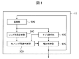
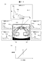
- FIG. 1 is a block diagram illustrating the internal functions of the surrounding environment recognition apparatus.
- the on-vehicle ambient environment recognition device 10 in the present embodiment recognizes the ambient environment of a vehicle based on an image obtained by capturing an external environment with an on-vehicle camera.
- the ambient environment recognition device 10 includes an in-vehicle camera that captures the outside of the vehicle and a recognition device that recognizes the surrounding environment based on an image captured by the in-vehicle camera. Any configuration that can acquire an external image captured by an in-vehicle camera or the like is not essential.
- the surrounding environment recognition device 10 includes an imaging unit 100, a lens state diagnosis unit 200, a sensing range determination unit 300, an application execution unit 400, and a notification control unit 500.
- the imaging unit 100 acquires, for example, an image around the vehicle captured by the on-board cameras 101 (see FIG. 6) attached to the front, rear, left and right of the vehicle body (image acquisition unit).
- the application execution unit 400 recognizes an object from the image acquired by the imaging unit 100 and executes various applications (hereinafter, applications) such as pedestrian detection and vehicle detection.
- the lens state diagnosis unit 200 diagnoses the lens state of the in-vehicle camera 101 based on the image acquired by the imaging unit 100.
- the in-vehicle camera 101 includes an image sensor such as a CMOS and an optical lens arranged in front of the image sensor.
- the lens in the present embodiment is not limited to a lens with a degree of focus adjustment, and is generally an optical glass (for example, a filter lens for preventing dirt) disposed in front of the image sensor. A polarizing lens, etc.).
- the lens state diagnosis unit 200 diagnoses dirt due to lens deposits, cloudiness, water droplets, and the like. For example, when the in-vehicle camera 101 is disposed outside the vehicle, dirt, dirt, insects, or other deposits adhere to the lens, or become white and cloudy like polished glass due to dust or scales, and water droplets themselves adhere. As a result, the lens may become dirty. If the lens of the in-vehicle camera 101 becomes dirty, it may be difficult to recognize an object due to hiding part or all of the background imaged in the image, blurring due to low definition, or distortion of the background. is there.
- the sensing range determination unit 300 determines a sensing possible range where the recognition target can be recognized based on the lens state diagnosed by the lens state diagnosis unit 200.
- the sensing possible range changes according to the degree of contamination such as the attachment position and size of the attachment to the lens, but also changes depending on the application executed by the application execution unit 400. For example, even when the degree of dirt on the lens and the distance to the object are the same, the recognition object of the app is relatively large, such as a vehicle, than the relatively small object, such as a pedestrian. , Sensing possible range is widened.
- the notification control unit 500 performs control to notify the user of at least one of the sensing possible range and the sensing impossible range based on information from the sensing range determination unit 300.
- the notification control unit 500 displays a sensing possible range to the user from, for example, an in-vehicle monitor or an alarm device, or informs the user of a change in the sensing possible range by flowing an alarm sound or a message.
- Information can be provided to the vehicle control device according to the sensing possible range so that it can be used for control.
- FIG. 6 is an example of the system configuration of the vehicle, and is a schematic diagram illustrating the overall configuration of the in-vehicle camera system.
- the surrounding environment recognition device 10 includes an internal function of the image processing device 2 that performs image processing of the in-vehicle camera 101 and an internal control of the vehicle control device 3 that performs notification to the driver and vehicle control based on the processing result from the image processing device. It is configured using functions.
- the image processing device 2 includes, for example, a lens state diagnosis unit 200, a sensing range determination unit 300, and an application unit 400, and the vehicle control device 3 includes a notification control unit 500.
- the vehicle 1 includes a plurality of in-vehicle cameras 101, for example, a front camera 101a that images the front of the vehicle 1, a rear camera 101b that images the rear, a left camera 101c that images the left side, and a right camera 101d that images the right side. It has four in-vehicle cameras 101 and can continuously capture the periphery of the vehicle 1 over the entire circumference.
- the in-vehicle camera 101 is not limited to a plurality, and may be a single one, and is not limited to the one that captures an image over the entire circumference, but only the front or the rear. It may be.
- the left and right in-vehicle cameras 101 may be cameras mounted on side mirrors, or cameras installed instead of side mirrors.
- the notification control unit 500 is an interface with the user, and is installed on hardware different from the image processing apparatus 2.
- the notification control unit 500 uses the result executed by the application execution unit 400 to perform control for realizing the preventive safety function and the convenience function.
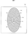
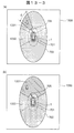
- FIG. 7 is a diagram illustrating an example of a screen displayed on the in-vehicle monitor.
- an overhead display method for presenting the applicable sensing range to the in-vehicle monitor 700 in a distance space as seen from above the vehicle (vehicle 1). Has traditionally existed.
- a minimum sensing line 701 capable of sensing (recognizing) an object closest to the vehicle 1 by a predetermined application is indicated by a small ellipse surrounding the vehicle 1, and an object farthest from the vehicle 1 can be sensed by the same application.
- the (recognizable) maximum sensing line 702 is shown as a large ellipse.
- the sensing range 704 is between the minimum sensing line 701 and the maximum sensing line 702. In a normal state where the lens is not soiled, the entire sensing range 704 is a sensing possible range.
- symbol 703 shown with a broken line in a figure shows the part with which the imaging range of a vehicle-mounted camera adjacent to each other overlaps.
- the sensing range 704 is set according to the application to be executed. For example, when the object of the application is relatively large like the vehicle 1, the maximum sensing line 702 and the minimum sensing line 701 are respectively large, and when the object is relatively small such as a pedestrian, the maximum sensing line 702 and the minimum sensing line are detected. Each line 701 becomes smaller.
- control is performed to notify the user that the application is in a degraded state.
- a sensing possible range and a sensing impossible range are visually displayed from the sensing range 704 on an in-vehicle monitor or the like, and the performance degradation state can be clearly communicated to the user.
- the detectable distance from the vehicle 1 can be easily grasped, and the degree of the decrease in sensing ability due to the performance degradation can be presented in an easy-to-understand manner.
- an LED provided on a meter panel or the like in the passenger compartment may be turned on, or the user may be informed that the operation of the application is in a degraded state by a warning sound or vibration.
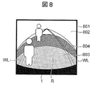
- FIG. 8 is a diagram showing an example of a screen displayed on the in-vehicle monitor.
- the in-vehicle monitor 801 displays an image 802 captured by the in-vehicle camera 101 at the front of the vehicle, and a sensing enabled region 803 and a sensing impossible region 804 superimposed on the image 802.
- the road R in front of the vehicle 1 and the left and right white lines WL indicating the traveling lane are imaged.
- “It is better to wipe away because the distance is not visible in the case of this level of dirt”, so the lens state and the sensing possible region 803 can be shown at the same time. Can be communicated in an easy-to-understand manner.
- FIG. 9 is a diagram illustrating an example of an image displayed on the windshield of the vehicle.
- a head-up display HUD
- HUD head-up display
- the sensing possible region 803 and the sensing impossible region 804 are presented to the real world by superimposed display on the road surface using the lower side of the windshield 901 or superimposed display in the air using the upper side of the windshield 901. May be.
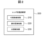
- FIG. 2 is a block diagram for explaining the internal functions of the lens state diagnosis unit 200.
- the lens state diagnosis unit 200 includes an adhering matter detection unit 210, a sharpness detection unit 220, and a water droplet detection unit 230, and each attached to the lens of the in-vehicle camera 101 based on the image acquired by the imaging unit 100. Diagnose the soiling status according to the type.
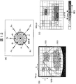
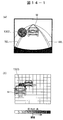
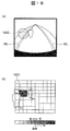
- FIG. 10A and 10B are diagrams for explaining a method for detecting an adhering matter attached to a lens.
- FIG. 10A shows an image 1001 obtained by imaging the front with the in-vehicle camera 101, and FIGS. It is a figure explaining the method to detect a deposit
- the image 1001 is contaminated with a plurality of deposits 1002 attached to the lens.
- the adhering matter detection unit 210 detects an adhering matter adhering to the lens, for example, an adhering matter 1002 that blocks the state of the background like mud.
- an adhering matter 1002 that blocks the state of the background like mud.
- the deposit 1002 can be detected by detecting an area where the luminance change is small.
- the adhering matter detection unit 210 divides the image area of the image 1001 into a plurality of blocks A (x, y) as shown in FIG.
- the luminance of each pixel of the image 1001 is detected, and the total luminance I t (x, y) of each pixel included in the block A (x, y) is calculated for each block A (x, y). calculate.
- the difference ⁇ I (x, y) between I t (x, y) calculated for the captured image of the current frame and I t ⁇ 1 (x, y) calculated in the same manner for the captured image of the previous frame is calculated for each block A. Calculate for each (x, y).
- a block A (x, y) in which the difference ⁇ I (x, y) is smaller than the surrounding blocks is detected, and a score SA (x, y) corresponding to the block A (x, y) is obtained. It is increased by a predetermined value, for example, “1”.
- the adhering matter detection unit 210 acquires an elapsed time tA since the score SA (x, y) of each block A (x, y) is initialized. . Then, the score SA (x, y) of each block A (x, y) is divided by the elapsed time tA to calculate the time average SA (x, y) / tA of the score SA (x, y). . The adhering matter detection unit 210 calculates the sum of the time average SA (x, y) / tA of all blocks A (x, y), and divides it by the total number of blocks in the captured image to obtain the score average SA_ave. calculate.
- the score average SA_ave increases for each frame that is sequentially captured. In other words, when the score average SA_ave is large, there is a high probability that mud or the like has adhered to the lens for a long time. It is determined whether the time average SA (x, y) / tA exceeds a predetermined threshold value, and it is determined that the area exceeding the threshold value is an area where mud adheres and the background cannot be seen (attachment area). This is used to calculate the sensing range of each application according to the size of the area exceeding the threshold. Further, a final determination is made as to whether or not each application can operate using the score average SA_ave.
- FIG. 10C shows an example of a score, and all blocks are shown with shades of color according to the score. And when a score is more than a predetermined threshold, it judges with the field 1012 where the background cannot be seen with a deposit.
- FIG. 11 is a diagram illustrating a method for detecting the sharpness of a lens.
- the sharpness detection unit 220 detects the lens state as a sharpness index as to whether the lens is clear or unclear.
- the state where the lens is unclear is, for example, that the surface of the lens becomes white and turbid due to dirt, the contrast becomes low and the contour of the object becomes blurred, and the degree is indicated by the sharpness.
- the sharpness detection unit 220 has an upper left detection region BG_L (Background Left), an upper detection region BG_T (Background Top), and an upper right detection region at positions where a horizon line is to appear in the image 1001.
- Set BG_R Background Right
- the upper detection area BG_T is set at a position including a vanishing point and a horizon where two lane marks WL provided parallel to each other on the road surface intersect each other at a distance.
- the upper left detection area BG_L is set on the left side of the upper detection area BG_T
- the upper right detection area BG_R is set on the right side of the upper detection area BG_T.
- Each area is set to an area including the horizon so that an edge is always included on the image. Also, a lower left detection region RD_L (Road Left) and a lower right detection region RD_R (Road Right) are set at positions where the lane mark WL is to appear in the image 1001.
- the sharpness detection unit 220 performs edge detection processing on the pixels in the upper left detection area BG_L, the upper detection area BG_T, the upper right detection area BG_R, the lower left detection area RD_L, and the lower right detection area RD_R.
- edge detection for the upper left detection area BG_L, the upper detection area BG_T, and the upper right detection area BG_R an edge such as a horizon is surely detected.
- an edge detection for the lower left detection area RD_L and the lower right detection area RD_R an edge such as a lane mark WL is detected.
- the sharpness detection unit 220 calculates the edge intensity for each pixel included in each detection region BG_L, BG_T, BG_R, RD_L, and RD_R. Then, the sharpness detection unit 220 calculates an average edge intensity of the edge intensity for each of the detection regions BG_L, BG_T, BG_R, RD_L, and RD_R, and determines the degree of sharpness based on the average value Blave. As shown in FIG. 11B, it is determined that the clearer lens is clearer as the edge strength is stronger, and the sharpness is set to be determined as a cloudy and unclear lens as the edge strength is weaker.
- FIG. 12 is a diagram for explaining a method of detecting water droplets attached to the lens.
- the water droplet detection unit 230 in FIG. 2 extracts a water droplet feature amount by performing luminance comparison with surrounding pixels as shown in FIG. 12A on the imaging screen.
- the water droplet detection unit 230 sets pixels that are predetermined distances (for example, 3 pix) in the upward direction, the upper right direction, the lower right direction, the upper left direction, and the lower left direction from the point of interest, as internal reference points Pi.
- a pixel further separated by a predetermined distance (for example, 3 pix) in five directions is set as the external reference point Po.
- the water droplet detection unit 230 compares the luminance for each internal reference point Pi and each external reference point Po.
- the water droplet detection unit 230 determines whether the luminance of the internal reference point Pi installed inside the edge of the water droplet 1202 is higher than the luminance of the external reference point Po for each of the five directions. In other words, the water droplet detection unit 230 determines whether or not the point of interest is the center of the water droplet 1202.
- the water droplet detection unit 230 has B (x, y) in the region shown in FIG.
- the score SB (x, y) is increased by a predetermined value, for example, “1”.
- the water droplet detection unit 230 performs the above-described determination for all pixels in the captured image, and then calculates the sum of the elapsed times tB of the score SB (x, y) of each block B (x, y) and divides it by Tb.
- the time average score SB (x, y) is calculated
- the score average SB_ave is calculated by dividing it by the total number of blocks in the captured image.
- a determination is made as to whether or not a specific threshold value ThrB is exceeded for each SB (x, y) of the divided region, and the result is scored, and the divided region exceeding the threshold value as shown in FIG. Is shown on the map, and the total score SB2 of the score on this map is calculated.
- the score average SB_ave increases for each frame. In other words, when the score average SB_ave is large, there is a high probability that water droplets are attached to the lens position.
- the water droplet detection unit 230 uses this score average SB_ave to determine the amount of water droplet adhesion on the lens.
- the amount of water droplets on the lens is equivalent to SB2, and this value is used to determine the failure of the entire system.
- the determination for each logic is separately used for determining the maximum detection distance based on the water drop occupancy rate.
- FIG. 12 (c) shows an example of a score, and all blocks are shown with shades of colors according to the score. If the score is equal to or greater than a predetermined threshold, it is determined that the background is not visible due to water droplets.
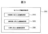
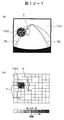
- FIG. 3 is a diagram for explaining the internal function of the sensing range determination unit.
- the sensing range determination unit 300 includes a distance conversion unit 310 according to the attached matter, a distance conversion unit 320 according to the sharpness, and a distance conversion unit 330 according to the water droplet, and the diagnosis result in the lens state diagnosis unit 200 Performs processing to determine the sensing range using.
- the sensing possible range in which the detection of each application can be guaranteed is converted using the detection result of the attached matter detecting unit 210.
- the distance conversion unit 320 according to the sharpness uses the detection result of the sharpness detection unit 220 to convert the sensing possible range that can guarantee the detection of each application.
- the sensing possible range that can guarantee the detection of each application is converted using the detection result of the water droplet detection unit 230.
- the distance conversion unit 310 calculates the sensing possible range according to the detection result of the deposit detection unit 210. Using the result of the adhering matter detection unit 210, it is determined whether or not the time average SA (x, y) / tA exceeds a predetermined threshold, and the area exceeding the threshold is attached with mud and the background cannot be seen. It is determined that For example, as shown in FIG. 13A, when a deposit 1302 such as mud adheres to the upper left on the image 1301, the time average SA (x, y) / of the region corresponding to the region of the deposit 1302 Assume that tA exceeds a predetermined threshold. As a result, an area where the background cannot be seen due to the adhering matter 1302 is selected on the image, as indicated by a dark area 1303 in FIG. 13-1 (b).
- the sensing range in this case is defined for each application. What is important here is that the size of the recognition object differs depending on each application.
- an example of an easy-to-understand pedestrian detection application will be described as an example.
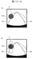
- FIGS. 13-2 (a) and (b) it is assumed that a pedestrian P overlaps an area portion where the background cannot be seen due to the deposit 1302.
- the size of the pedestrian P appears different depending on the distance in the depth direction.
- the percentage (rate) at which the deposit 1302 blocks the pedestrian P is increased, so that it is difficult to guarantee detection far away and in the left direction of the front fisheye camera.
- the pedestrian is 6.0 m away from the host vehicle, and most of the pedestrian is hidden behind the deposit 1302. Since only less than 40% is visible, the pedestrian detection unit 430 of the application execution unit 400 cannot recognize a pedestrian (unrecognizable).
- FIG. 13-2 (b) when the pedestrian is 1.0 m away from the own vehicle, 40% or more of the size of the pedestrian is visible. Can recognize pedestrians (can be recognized). This process is performed for each depth distance Z.
- the pedestrian assumes a standard body shape (standard size) with a height of 1.8 m, and calculates the size of the pedestrian P on the image 1301 for each depth distance Z from 1 m to 5 m. To do.
- the shape of the pedestrian P for each depth is compared with an area portion (attachment region) where the background is not visible due to the attachment 1302 such as mud, and the attachment 1302 may hide a maximum percentage of the pedestrian P. It is calculated whether or not there is a ratio (the rate at which the adhered region blocks the recognition object of the standard size). For example, the depth at which the pedestrian P may not be seen by 30% or more and the viewing angle ⁇ from the camera 101 are calculated.
- FIGS. 13-3 (a) and 13 (b) show a non-sensing range 1331 in which pedestrians cannot be recognized (sensing) and a recognizable range 1332 in a display unit 1330 such as an in-vehicle monitor. An example of the displayed state is shown.
- the sensing range determination unit 300 determines a sensing possible range in which a pedestrian can be sensed based on a lens state diagnosed by the lens state diagnosis unit 200 when an application is executed, and a sensing impossible range in which sensing is impossible.
- the sensing impossible range 1331 is set. Yes.
- the predetermined distance 705 is set so as to approach the vehicle 1 as the size of the deposit increases, and to move away from the vehicle 1 as the size of the deposit decreases.
- ⁇ that determines the width of the sensing impossible range 1331 is set in accordance with the size of the deposit.
- there is a high possibility that the deposit is attached to the in-vehicle camera 101a attached to the front portion of the vehicle 1, and the distant place is not visible due to the shadow of the deposit. All of the images far away from the predetermined distance 705 of the image captured by the vehicle-mounted camera 101 in the front of the vehicle are set to be unusable.
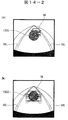
- the vehicle detection is similar to the concept of pedestrian detection, and the size of the vehicle M, which is the recognition target, is defined as a width of 1.8 m and a depth of 4.7 m. And a part different from the pedestrian P is a part which defines the direction of the vehicle M to be detected as the same as the lane recognition or the traveling direction of the host vehicle.
- the calculation is made assuming that the vehicle runs in the same direction as the preceding vehicle or the preceding vehicle in the adjacent lane. For example, as shown in FIG. 14A, the case where the preceding vehicle M running along the lane WL overlaps the left upper deposit 1302 is investigated according to depth. Since the vehicle M is larger than the pedestrian P, it can be detected farther than the pedestrian P.
- the vehicle M is a rigid body compared with the pedestrian P and is an artificial object, even if the percentage (ratio) invisible compared with the pedestrian P becomes high, a detection is guaranteeable.
- the farther the vehicle M is the higher the percentage that the deposit 1302 blocks the vehicle M increases. This makes it difficult to guarantee detection.
- the preceding vehicle is 7.0 m away from the host vehicle, and the vehicle detection unit 420 cannot recognize the vehicle (cannot be recognized), but the example shown in FIG. 14-2 (b) Then, the preceding vehicle is 3.0 m away from the host vehicle, and the vehicle detection unit 420 can recognize the vehicle (recognition is possible).
- Lane recognition is similar to pedestrian detection and vehicle detection as its basic concept. The difference is that the recognition object has no fixed size. However, an important idea is that, when recognizing the lane WL, the distance from 10 m to the vicinity 50 cm is recognized and dealt with in the first place, and whether or not the depth from what m to what m can be seen. It is determined which range on the road surface is to be hidden using the camera geometry for the dirty area on the screen.
- the parking frame is present on the road surface in the same manner as the white line, but unlike the white line, the rough size of the object can be regarded as known.
- a parking frame is defined as having a width of 2.2 m and a depth of 5 m, and what percentage may be hidden inside the frame in this area calculate.
- only the frame line is important, and only the inside of the frame can be detected even if it is dirty with mud, but if the vehicle moves and disappears, the performance as an application can not be guaranteed, so there is nothing inside the frame. It is calculated whether there is a possibility that the percentage becomes invisible with mud.
- a three-dimensional object of the assumed size that is the detection target is assumed, and the three-dimensional position is defined as the depth direction on the road surface.
- the percentage of how much the three-dimensional object is blocked on the image is calculated. If the percentage obstructed by the adhering material exceeds the threshold, it is determined that the three-dimensional position is unrecognizable, and if the percentage does not exceed the threshold, it is determined that recognition is possible.
- the place where the detection rate of the detection target is reduced is three-dimensional around the own vehicle. Estimate as an area. However, when there is no definition of the object size as in the case of obstacle detection, a fixed size at the foot position is assumed, and it may be substituted for the determination of whether or not this area is visible.
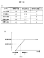
- FIG. 16 is a table showing the standard size and durability shielding rate of the recognition target object of the application.
- the durable shielding rate defines what percentage of the size of the adhered object on the image is smaller than the size of the recognition object and can be recognized as the recognition object.
- the vehicle detection the vehicle can be recognized when the deposit is 50% or less of the vehicle
- the pedestrian detection the vehicle can be recognized when the deposit is 40% or less of the pedestrian. Is set to As described above, by estimating the camera sensing range both as an image and as a three-dimensional area, it is possible to easily convey to the user the sensing range that changes according to the lens state of the camera.
- the guaranteed detection distance is calculated based on the average value Brave of the sharpness as a result of the sharpness detection unit 220.
- the standard definition ⁇ 1 of the lens definition necessary for obtaining the edge strength necessary for recognizing the recognition target object up to the maximum detection distance is set.
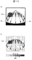
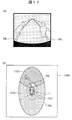
- FIG. 18A is a diagram illustrating the relationship between the edge strength of each application and the maximum detection distance.
- FIG. 18B is a graph showing the relationship between the detection distance and the sharpness, and the guaranteed detection distance of the application changes when the sharpness Brave exists between the standard sharpness ⁇ 1 and the minimum sharpness ⁇ 2. It is shown that.
- the setting of each application has a maximum detection distance of each application, and when guaranteeing the range at this maximum detection distance, the setting of each application is set for each application. It is necessary for the average value “Blave” of the definition to indicate the standard definition ⁇ 1 or more. As the average value “Blave” of the sharpness decreases from the standard sharpness ⁇ 1, the guaranteed detection distance decreases, indicating that the detection is impossible when the minimum sharpness ⁇ 2 of the target application is reached.
- the maximum detection distance is 10 m when the standard definition is 0.4, and the minimum detection distance is 0 m when the minimum definition is 0.15.
- the maximum detection distance is 5 m when the standard definition is 0.5, and the minimum detection distance is 0 m when the minimum definition is 0.2.
- FIG. 17 is a diagram illustrating a method in which the sensing range determination unit 300 determines a sensing possible range according to the sharpness.
- FIG. 17A illustrates an example in which a low-definition state is displayed on the in-vehicle monitor.
- FIG. 17B shows a sensing impossible range 1331 in which a pedestrian cannot be recognized (sensing) and a recognizable sensing possible range 1332 on a display unit 1330 such as an in-vehicle monitor. An example of the state is shown.
- the predetermined distance 705 is set such that the closer to the minimum definition, the closer to the vehicle 1 and the closer to the standard definition, the farther from the vehicle 1.
- the distance conversion unit 330 corresponding to the water droplet shown in FIG. 3 calculates the sensing possible range for each application based on the result of the water droplet detection unit 230. Based on SB (x, y) and threshold value ThrB as a result of the water droplet detection, an area is calculated when it is within the processing area of each application and SB (x, y) exceeds threshold value ThrB.
- the maximum detection distance is determined using this water drop occupancy rate.
- the lens state is likely to change quickly. For example, if the lens condition changes due to the effects of rain that falls or the water on the road is rolled up, the lens condition changes. There is a high possibility that the lens state can always change, such as a decrease in water droplets. For this reason, the location 1903 where the field of view is hindered by the current position of the water droplet is not determined as a region outside the field of view or an undetectable region. Since the position of a small object cannot be correctly determined, the operation is guaranteed according to the lens state by setting the detection distance short.
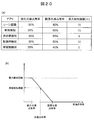
- the distance conversion unit 330 calculates the guaranteed detection distance from the water droplet occupancy rate in consideration of this processing region. Furthermore, from the value of the water drop occupancy rate, the water drop occupancy rate that can guarantee the maximum detection distance of the application as it is is defined as the durable water drop occupancy rate shown in FIG. Furthermore, the water droplet occupancy rate at which detection of the application cannot be guaranteed because the operation of the application itself cannot be performed is defined as the limit water droplet occupancy rate.
- the state of the limit water drop occupancy rate indicates a state where the guaranteed detection distance is 0 m, and the guarantee detection distance linearly decreases between the durable water drop occupancy rate and the limit water drop occupancy rate as shown in FIG. The mechanism is as follows.
- the amount of water droplet adhesion within the range to be image-processed to recognize the recognition object is calculated and converted as the degree of influence of false detection or non-detection for each application.
- water drop durability For example, when the water drop occupancy rate in the lane recognition processing area is high, a large amount of water drops are attached to the area where the lane is expected to exist on the image, and the lane may not be recognized properly. Therefore, detection of distant objects that are particularly susceptible to the distortion of water drops is excluded from the guarantee when the water drop occupancy is slightly increased, and the nearby distance is gradually excluded from the guarantee as the water drop occupancy increases.
- a maximum detection distance of 10 m can be guaranteed when the water drop occupancy is up to 35% or less, and the minimum detection distance is 0 m when the limit water drop occupancy is greater than 60%.
- the maximum detection distance of 5 m can be guaranteed when the water drop occupancy is 30% and the minimum detection distance is 0 m when the limit water drop occupancy is greater than 50%.
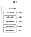
- FIG. 4 is a block diagram for explaining the internal functions of the application execution unit 400.
- the application execution unit 400 includes, for example, a lane recognition unit 410, a vehicle detection unit 420, a pedestrian detection unit 430, a parking frame detection unit 440, and an obstacle detection unit 450, and is executed based on preset conditions.
- the application execution unit 400 includes, for example, a lane recognition unit 410, a vehicle detection unit 420, a pedestrian detection unit 430, a parking frame detection unit 440, and an obstacle detection unit 450, and is executed based on preset conditions.
- the application execution unit 400 uses images captured by the in-vehicle camera 101 as input, and executes various applications that use image recognition in order to improve preventive safety and convenience.
- the lane recognition unit 410 executes lane recognition used for, for example, warning and prevention of lane departure, lane maintenance support, deceleration before a curve, and the like.
- the lane recognition unit 410 extracts the feature amount of the white line WL from the image, and evaluates the linearity and curvilinearity of the feature amount to determine in which lateral position the host vehicle is in the lane and to the lane. Estimate yaw angle indicating inclination, curvature of lane, etc.
- the vehicle detection unit 420 extracts a square shape as a feature amount on the image of the back surface of the preceding vehicle, and extracts vehicle candidates. For this candidate, it is confirmed that it is not a stationary object that moves on the screen at its own vehicle speed unlike the background. Further, by applying pattern matching to the candidate area, it may be used for narrowing down candidates. In this way, by narrowing down the vehicle candidates and estimating the relative position with respect to the host vehicle, it is determined whether there is a risk of contact with the host vehicle or a collision, and whether it is an alarm target or a control target is determined. carry out. When used as an application such as preceding vehicle tracking, the host vehicle speed is controlled according to the relative distance of the preceding vehicle to automatically track the vehicle so that it does not collide with the preceding vehicle.
- the pedestrian detection unit 430 narrows down pedestrian candidates by extracting feature amounts based on the pedestrian's head shape or leg shape. Furthermore, pedestrian detection during movement is performed with reference to whether the movement of the pedestrian candidate is in the direction of the collision as compared to the movement of the background of the stationary object accompanying the movement of the host vehicle. By using pattern matching, stationary pedestrians may be targeted. By detecting a pedestrian in this way, it becomes possible to perform warning and control for a jumping out while traveling. In addition, it is a very useful application even in low speed areas such as parking lots and intersections even when driving on the road.
- the parking frame detection unit 440 extracts the feature amount of the white line in the same manner as the white line recognition at a low speed such as 20 km / h or less. Next, straight lines of any inclination existing on the screen are extracted by Hough transform. Further, instead of finding a simple white line, it is determined whether or not the parking frame prompts the driver to park. The width of the left and right frames is such that the vehicle 1 can be stopped, and if the vehicle is parked, it is detected whether it is a parking area by detecting the vehicle stop block that is behind or in front of the vehicle 1 or the front and back white lines. To do.
- the user can select the parking frame from multiple frame candidates, but when only the nearby parking frame is visible, It cannot be recognized unless it is close to the parking space. Moreover, since it is utilized for the parking control of the vehicle 1 fundamentally, when recognition is unstable, it notifies a user that it cannot control.
- the obstacle detection unit 450 extracts characteristic points on the image.
- a feature point having a unique feature on an image composed of corners of an object is associated with a feature point having the same feature when the change on the image is small even in the next frame. be able to.
- Three-dimensional reconstruction is performed using the feature points that are compatible between these two frames or between multiple frames. At this time, an obstacle that may cause a collision with the host vehicle is detected.
- FIG. 5 is a block diagram illustrating the internal functions of the notification control unit 500.
- the notification control unit 500 includes, for example, an alarm unit 510, a control unit 520, a display unit 530, a dirt removing unit 540, an LED display unit 550, and the like.
- the notification control unit 500 serves as an interface part that receives the determination result of the sensing range determination unit 300 and transmits the information to the user. For example, in a normal state such as when there is no sensing impossible range within the sensing range required by the app, and everything is within the sensing possible range, the green LED is lit on, and the green LED is turned on in suppression mode. Blink. In the system give-up state where there is a possibility of early recovery, such as in rainy weather, the orange LED may be lit and long-term dirt such as mud or cloudiness may be attached to the lens. If the user does not wipe the lens and the system give-up state is unlikely to be restored, the red LED is turned on in the system giving up status, etc.
- the system configuration is such that the user can be warned of an abnormal state due to lens contamination of the system.
- the system give-up state indicates a state in which an application for recognizing a recognition target object is stopped for preventive safety when it is determined that imaging appropriate for image recognition is difficult due to an attachment on the lens surface.
- the CAN output is stopped even if the recognition itself does not stop, or the recognition result of the recognition target object is displayed in the alarm, vehicle control, display on the screen, etc. that will be the final output even if the CAN output remains output Indicates a state in which the message is not transmitted to the user.
- the system give-up state instead of presenting the recognition result of the recognition object, the user may be notified that the recognition system is in the give-up state, or may be notified by voice or the like.
- the display that was lit red at the time of long-term give-up May be changed to orange to convey the improvement of the lens.
- the preventive safety function can be performed without the user's knowledge. Make sure you have never stopped.
- FIG. 21 is a diagram comparing sensing possible ranges according to recognition objects.
- the size and position of the attached object attached to the front in-vehicle camera 101 are the same, and there are three types of recognition objects for each app: a vehicle, a pedestrian, and an obstacle, the size of the recognition object is individually Since they are different, the sensing ranges are also different from each other.
- the recognition target is a vehicle
- the length La2 of the minimum sensing range 2101 in front of the vehicle and the length La1 of the maximum sensing range 2102 in front of the vehicle are the length Lp2 of the pedestrian minimum sensing range 2111 in front of the vehicle.
- the length Lm2 of the front of the vehicle in the minimum sensing range 2121 of the obstacle, and the length Lm1 of the front of the vehicle in the maximum sensing range 2122 are the minimum of the pedestrian.
- the length Lp2 of the sensing range 2111 ahead of the vehicle and the length Lp1 of the maximum sensing range 2112 ahead of the vehicle are smaller.
- the angle ⁇ at which the background is hidden by the adhering substance is substantially the same between the applications, but is corrected according to the size of the recognition object.
- the sensing possible range according to the lens dirt of the in-vehicle camera 101 can be shown to the user, and the user knows the range in which the recognition target object of the app can be recognized. Can do. Therefore, it is possible to prevent the user from overconfidencing the app and losing attention to the surrounding environment, and to encourage driving with more care.
- the present invention is not limited to the above-described embodiments, and various designs can be made without departing from the spirit of the present invention described in the claims. It can be changed.
- the above-described embodiment has been described in detail for easy understanding of the present invention, and is not necessarily limited to one having all the configurations described.
- a part of the configuration of an embodiment can be replaced with the configuration of another embodiment, and the configuration of another embodiment can be added to the configuration of an embodiment.
Abstract
The present invention addresses the problem of providing a surrounding environment recognition device that presents to a user a sensing-enabled range that varies depending on a contamination state of a lens. The present invention is characterized by comprising: an image-capturing unit (100) that acquires an image; an application execution unit (400) that executes an application for recognizing an object to be recognized from the image; a lens state diagnosis unit (200) that diagnoses the lens state of a camera on the basis of the image; a sensing range determination unit (300) that determines a sensing-enabled range allowing the sensing of the object to be recognized with the lens state diagnosed by the lens state diagnosis unit when the application is executed, and a sensing-disabled range not enabling the sensing of the object to be recognized; and a notification control unit (500) that notifies the sensing-enabled range of the sensing range determination unit.
Description
本発明は、カメラで撮像した画像に基づいて周囲の環境を認識する周囲環境認識装置に関する。
The present invention relates to an ambient environment recognition apparatus that recognizes an ambient environment based on an image captured by a camera.
車両に設置されたカメラで周囲を撮像した画像から周囲環境を認識するアプリケーションの製品化が増加傾向にある。その中で、車室外にカメラが設置されている場合に、カメラのレンズが正常に認識できる状態となっているかどうかを判定する技術がある(特許文献1)。特許文献1の技術は、カメラのレンズに付着した異物等を検出し、その領域の割合が閾値を超えると、周囲環境を認識するアプリケーションを停止して、アプリケーションが停止したことをユーザに報知するものである。また、車両走行時の画像から背景が動くにも関わらず、変化しない不動領域を検出し、この不動領域を除いた領域のみで物体検出する技術も、従来から種々存在する。
・ Production of applications that recognize the surrounding environment from an image of the surroundings taken by a camera installed in the vehicle is increasing. Among them, there is a technique for determining whether or not a lens of a camera can be normally recognized when a camera is installed outside the vehicle compartment (Patent Document 1). The technique of Patent Literature 1 detects foreign matter or the like attached to the lens of a camera, and when the ratio of the area exceeds a threshold, the application that recognizes the surrounding environment is stopped and the user is notified that the application has stopped. Is. There have also been various techniques for detecting an immovable area that does not change despite the background moving from an image when the vehicle is running and detecting an object only in an area excluding the immovable area.
しかしながら、認識対象物を認識可能な範囲がどのように変化したかをユーザに提示するものはない。従来のように、レンズ汚れ時に、アプリケーションを停止するだけ、あるいは、不動領域を除いた領域のみで物体検出するだけでは、ユーザがアプリを過信して、周囲環境への注意が疎かになるおそれもある。
However, there is nothing that shows the user how the range in which the recognition object can be recognized has changed. As in the past, when the lens is dirty, simply stopping the application, or just detecting the object only in the area other than the non-moving area, may cause the user to overtrust the application and lose attention to the surrounding environment. is there.
本発明は、上記の点に鑑みてなされたものであり、その目的とするところは、レンズの汚れ状態に応じて変化するセンシング可能範囲をユーザに提示する周囲環境認識装置を提供することである。
The present invention has been made in view of the above points, and an object of the present invention is to provide an ambient environment recognition device that presents a user with a sensing possible range that changes according to the dirt state of a lens. .
上記課題を解決する本発明の周囲環境認識装置は、カメラで外部環境を撮像した画像に基づいて周囲環境を認識する周囲環境認識装置であって、前記画像を取得する画像取得部と、前記画像から認識対象物を認識するアプリケーションを実行するアプリ実行部と、前記画像に基づいて前記カメラのレンズ状態を診断するレンズ状態診断部と、前記アプリケーションを実行した場合に前記レンズ状態診断部で診断したレンズ状態によって前記認識対象物をセンシングすることが可能なセンシング可能範囲と、前記認識対象物をセンシング不可能なセンシング不可能範囲を判断するセンシング範囲判断部と、該センシング範囲判断部のセンシング可能範囲とセンシング不可能範囲との少なくとも一方を報知する報知制御部を有することを特徴としている。
An ambient environment recognition apparatus of the present invention that solves the above problem is an ambient environment recognition apparatus that recognizes an ambient environment based on an image obtained by capturing an external environment with a camera, an image acquisition unit that acquires the image, and the image An application execution unit that executes an application for recognizing a recognition object from the lens, a lens state diagnosis unit that diagnoses a lens state of the camera based on the image, and a diagnosis performed by the lens state diagnosis unit when the application is executed Sensable range capable of sensing the recognition target object according to a lens state, a sensing range determination unit for determining a non-sensable range incapable of sensing the recognition target object, and a sensing possible range of the sensing range determination unit And a notification control unit that notifies at least one of the sensing impossible range, To have.
本発明によれば、レンズ汚れに起因した現状の画像認識アプリケーションの性能低下状況をユーザに報知することによって、ユーザのカメラ認識機能への過信を抑制し、ユーザに対してレンズ汚れ時には周囲環境により注意して運転することを促すことができる。なお、上記した以外の課題、構成及び効果は、以下の実施形態の説明により明らかにされる。
According to the present invention, it is possible to suppress overconfidence in the user's camera recognition function by notifying the user of the performance degradation status of the current image recognition application due to lens contamination, and to the user depending on the surrounding environment when the lens is dirty. You can encourage driving with caution. Problems, configurations, and effects other than those described above will be clarified by the following description of the embodiments.
次に、本発明の周囲環境認識装置が適用される実施形態について図面を用いて以下に説明する。なお、以下の実施例では、本発明の周囲環境認識装置を自動車などの車両に搭載される車載用環境認識装置に適用した場合を例に説明するが、車載用に限定されるものではなく、建築機器、ロボット、監視カメラ、農業機器などにも適用することができる。
Next, an embodiment to which the ambient environment recognition apparatus of the present invention is applied will be described below with reference to the drawings. In the following embodiments, the case where the ambient environment recognition device of the present invention is applied to an in-vehicle environment recognition device mounted on a vehicle such as an automobile will be described as an example, but it is not limited to in-vehicle use. It can also be applied to construction equipment, robots, surveillance cameras, agricultural equipment, and the like.
図1は、周囲環境認識装置の内部機能を説明するブロック図である。
本実施の形態における車載用の周囲環境認識装置10は、車載カメラで外部環境を撮像した画像に基づいて車両の周囲環境を認識するものである。周囲環境認識装置10は、車両の外部を撮像する車載カメラと、車載カメラで撮像した画像に基づいて周囲の環境を認識する認識装置を有しているが、車載カメラ自体は周囲環境認識装置の必須の構成要素ではなく、車載カメラ等で撮像した外部の画像を取得することができる構成であればよい。 FIG. 1 is a block diagram illustrating the internal functions of the surrounding environment recognition apparatus.
The on-vehicle ambientenvironment recognition device 10 in the present embodiment recognizes the ambient environment of a vehicle based on an image obtained by capturing an external environment with an on-vehicle camera. The ambient environment recognition device 10 includes an in-vehicle camera that captures the outside of the vehicle and a recognition device that recognizes the surrounding environment based on an image captured by the in-vehicle camera. Any configuration that can acquire an external image captured by an in-vehicle camera or the like is not essential.
本実施の形態における車載用の周囲環境認識装置10は、車載カメラで外部環境を撮像した画像に基づいて車両の周囲環境を認識するものである。周囲環境認識装置10は、車両の外部を撮像する車載カメラと、車載カメラで撮像した画像に基づいて周囲の環境を認識する認識装置を有しているが、車載カメラ自体は周囲環境認識装置の必須の構成要素ではなく、車載カメラ等で撮像した外部の画像を取得することができる構成であればよい。 FIG. 1 is a block diagram illustrating the internal functions of the surrounding environment recognition apparatus.
The on-vehicle ambient
周囲環境認識装置10は、図1に示すように、撮像部100と、レンズ状態診断部200と、センシング範囲判断部300と、アプリ実行部400と、報知制御部500を有している。
As shown in FIG. 1, the surrounding environment recognition device 10 includes an imaging unit 100, a lens state diagnosis unit 200, a sensing range determination unit 300, an application execution unit 400, and a notification control unit 500.
撮像部100は、例えば車体の前後左右に取り付けられた車載カメラ101(図6を参照)によって撮像された車両周囲の画像を取得する(画像取得部)。アプリ実行部400は、撮像部100が取得した画像から対象物を認識して、歩行者検知や車両検知などの各種のアプリケーション(以下、アプリ)を実行する。
The imaging unit 100 acquires, for example, an image around the vehicle captured by the on-board cameras 101 (see FIG. 6) attached to the front, rear, left and right of the vehicle body (image acquisition unit). The application execution unit 400 recognizes an object from the image acquired by the imaging unit 100 and executes various applications (hereinafter, applications) such as pedestrian detection and vehicle detection.
レンズ状態診断部200は、撮像部100で取得した画像に基づいて車載カメラ101のレンズの状態を診断する。車載カメラ101は、CMOS等の撮像素子と、撮像素子の前に配置される光学系のレンズを有している。なお、本実施形態におけるレンズは、ピントを調整する度付のレンズのみに限定されるものではなく、一般的に撮像素子の前方に配置される光学系のガラス(例えば汚れ防止用のフィルタレンズや偏光レンズなど)も含まれる。
The lens state diagnosis unit 200 diagnoses the lens state of the in-vehicle camera 101 based on the image acquired by the imaging unit 100. The in-vehicle camera 101 includes an image sensor such as a CMOS and an optical lens arranged in front of the image sensor. Note that the lens in the present embodiment is not limited to a lens with a degree of focus adjustment, and is generally an optical glass (for example, a filter lens for preventing dirt) disposed in front of the image sensor. A polarizing lens, etc.).
レンズ状態診断部200は、レンズの付着物や白濁、水滴等による汚れを診断する。車載カメラ101は、例えば車外に配置されている場合、泥やゴミ、虫などの付着物がレンズに付着し、あるいは塵埃や水垢などによって磨りガラスのように白く白濁し、また、水滴自体が付着して、レンズが汚れるおそれがある。車載カメラ101のレンズが汚れると、画像に撮像されている背景の一部または全部が隠れたり、鮮明度が低くなってぼやけたり、背景が歪むなどして対象物の認識が困難となるおそれがある。
The lens state diagnosis unit 200 diagnoses dirt due to lens deposits, cloudiness, water droplets, and the like. For example, when the in-vehicle camera 101 is disposed outside the vehicle, dirt, dirt, insects, or other deposits adhere to the lens, or become white and cloudy like polished glass due to dust or scales, and water droplets themselves adhere. As a result, the lens may become dirty. If the lens of the in-vehicle camera 101 becomes dirty, it may be difficult to recognize an object due to hiding part or all of the background imaged in the image, blurring due to low definition, or distortion of the background. is there.
センシング範囲判断部300は、レンズ状態診断部200で診断したレンズ状態に基づいて認識対象物を認識可能なセンシング可能範囲を判断する。センシング可能範囲は、レンズに対する付着物の付着位置、大きさなどの汚れ度合いに応じて変化するが、それだけではなく、アプリ実行部400で実行されるアプリに応じても変化する。例えば、レンズの汚れ度合い及び対象物までの距離が同じ場合であっても、アプリの認識対象物が車両などのように比較的大きいものの方が、歩行者などのように比較的小さいものよりも、センシング可能範囲が広くなる。
The sensing range determination unit 300 determines a sensing possible range where the recognition target can be recognized based on the lens state diagnosed by the lens state diagnosis unit 200. The sensing possible range changes according to the degree of contamination such as the attachment position and size of the attachment to the lens, but also changes depending on the application executed by the application execution unit 400. For example, even when the degree of dirt on the lens and the distance to the object are the same, the recognition object of the app is relatively large, such as a vehicle, than the relatively small object, such as a pedestrian. , Sensing possible range is widened.
報知制御部500は、センシング範囲判断部300からの情報に基づいて、センシング可能範囲とセンシング不可能範囲の少なくとも一方をユーザに報知する制御を行う。報知制御部500は、例えば車載モニタや警報装置からユーザにセンシング可能範囲を表示したり、警報音やメッセージ等を流すことでユーザにセンシング可能範囲の変化を報知し、また、車両制御装置が車両制御に用いることができるように、センシング可能範囲に応じて車両制御装置に情報を提供することができる。
The notification control unit 500 performs control to notify the user of at least one of the sensing possible range and the sensing impossible range based on information from the sensing range determination unit 300. The notification control unit 500 displays a sensing possible range to the user from, for example, an in-vehicle monitor or an alarm device, or informs the user of a change in the sensing possible range by flowing an alarm sound or a message. Information can be provided to the vehicle control device according to the sensing possible range so that it can be used for control.
図6は、車両のシステム構成の一例であって、車載カメラシステムの全体構成を説明する概略図である。周囲環境認識装置10は、車載カメラ101の画像処理を行う画像処理装置2の内部機能と、画像処理装置からの処理結果に基づいて運転者への報知や車両制御を行う車両制御装置3の内部機能とを用いて構成されている。画像処理装置2は、例えば、レンズ状態診断部200と、センシング範囲判断部300、アプリ部400を備えており、車両制御装置3は、報知制御部500を備えている。
FIG. 6 is an example of the system configuration of the vehicle, and is a schematic diagram illustrating the overall configuration of the in-vehicle camera system. The surrounding environment recognition device 10 includes an internal function of the image processing device 2 that performs image processing of the in-vehicle camera 101 and an internal control of the vehicle control device 3 that performs notification to the driver and vehicle control based on the processing result from the image processing device. It is configured using functions. The image processing device 2 includes, for example, a lens state diagnosis unit 200, a sensing range determination unit 300, and an application unit 400, and the vehicle control device 3 includes a notification control unit 500.
車両1は、複数の車載カメラ101、例えば車両1の前方を撮像する前方カメラ101a、後方を撮像する後部カメラ101b、左側方を撮像する左側部カメラ101c、右側方を撮像する右側部カメラ101dの4台の車載カメラ101を有しており、車両1の周囲を全周に亘って連続して撮像できるようになっている。なお、車載カメラ101は、複数に限定されるものではなく、単一のものであってもよく、また、全周に亘って撮像するものに限定されず、前方のみや後方のみを撮像するものであってもよい。
The vehicle 1 includes a plurality of in-vehicle cameras 101, for example, a front camera 101a that images the front of the vehicle 1, a rear camera 101b that images the rear, a left camera 101c that images the left side, and a right camera 101d that images the right side. It has four in-vehicle cameras 101 and can continuously capture the periphery of the vehicle 1 over the entire circumference. The in-vehicle camera 101 is not limited to a plurality, and may be a single one, and is not limited to the one that captures an image over the entire circumference, but only the front or the rear. It may be.
左右の車載カメラ101は、サイドミラーに装着されたカメラでもよく、また、サイドミラーの代わりに設置されたカメラでもよい。報知制御部500は、ユーザとのインタフェースであり、これは画像処理装置2とは別のハードウェア上に実装されている。報知制御部500は、アプリ実行部400において実行された結果を利用して、予防安全機能や利便性機能を実現する制御を実施する。
The left and right in-vehicle cameras 101 may be cameras mounted on side mirrors, or cameras installed instead of side mirrors. The notification control unit 500 is an interface with the user, and is installed on hardware different from the image processing apparatus 2. The notification control unit 500 uses the result executed by the application execution unit 400 to perform control for realizing the preventive safety function and the convenience function.
図7は、車載モニタに表示される画面の一例を示す図である。
システムが正常動作中で所定のアプリが実行中の場合に、アプリのセンシング可能範囲を、自車(車両1)の上から見たような距離空間のまま、車載モニタ700に提示する俯瞰表示方法が従来から存在する。 FIG. 7 is a diagram illustrating an example of a screen displayed on the in-vehicle monitor.
When the system is operating normally and a predetermined application is being executed, an overhead display method for presenting the applicable sensing range to the in-vehicle monitor 700 in a distance space as seen from above the vehicle (vehicle 1). Has traditionally existed.
システムが正常動作中で所定のアプリが実行中の場合に、アプリのセンシング可能範囲を、自車(車両1)の上から見たような距離空間のまま、車載モニタ700に提示する俯瞰表示方法が従来から存在する。 FIG. 7 is a diagram illustrating an example of a screen displayed on the in-vehicle monitor.
When the system is operating normally and a predetermined application is being executed, an overhead display method for presenting the applicable sensing range to the in-
所定のアプリにより車両1に最も近い対象物をセンシング可能(認識可能)な最小センシングライン701は、車両1の周囲を囲む小楕円で示され、同じアプリにより車両1から最も遠い対象物をセンシング可能(認識可能)な最大センシングライン702は、大楕円で示されている。最小センシングライン701と最大センシングライン702との間がセンシング範囲704となり、レンズに汚れがない通常状態の場合には、センシング範囲704全体がセンシング可能範囲となる。なお、図中に破線で示される符号703は、互いに隣り合う車載カメラの撮像範囲が重複する部分を示す。
A minimum sensing line 701 capable of sensing (recognizing) an object closest to the vehicle 1 by a predetermined application is indicated by a small ellipse surrounding the vehicle 1, and an object farthest from the vehicle 1 can be sensed by the same application. The (recognizable) maximum sensing line 702 is shown as a large ellipse. The sensing range 704 is between the minimum sensing line 701 and the maximum sensing line 702. In a normal state where the lens is not soiled, the entire sensing range 704 is a sensing possible range. In addition, the code | symbol 703 shown with a broken line in a figure shows the part with which the imaging range of a vehicle-mounted camera adjacent to each other overlaps.
センシング範囲704は、実行されるアプリに応じて設定される。例えばアプリの対象物が車両1のように比較的大きい場合には最大センシングライン702と最小センシングライン701はそれぞれ大きくなり、対象物が歩行者など比較的小さい場合には最大センシングライン702と最小センシングライン701はそれぞれ小さくなる。
The sensing range 704 is set according to the application to be executed. For example, when the object of the application is relatively large like the vehicle 1, the maximum sensing line 702 and the minimum sensing line 701 are respectively large, and when the object is relatively small such as a pedestrian, the maximum sensing line 702 and the minimum sensing line are detected. Each line 701 becomes smaller.
車載カメラ101のレンズに汚れ等がある場合、たとえセンシング範囲704内であったとしても、その汚れ等によって隠れている背景部分については認識対象物の検知が困難となり、アプリは所期の性能を発揮できない性能低下状態となるおそれがある。本発明の周囲環境認識装置では、アプリが性能低下状態となっていることをユーザに伝えるために報知する制御を行う。
When the lens of the in-vehicle camera 101 is contaminated, even if it is within the sensing range 704, it is difficult to detect the recognition target for the background portion hidden by the dirt, and the app has the expected performance. There is a risk of performance degradation that cannot be achieved. In the surrounding environment recognition apparatus of the present invention, control is performed to notify the user that the application is in a degraded state.
報知方法として、例えば車載モニタ等にセンシング範囲704からセンシング可能範囲とセンシング不可能範囲を視覚的に表示し、性能低下状態をユーザに明確に伝えることができる。この表示方法は、車両1からの検知可能な距離が把握しやすく、性能低下によるセンシング能力の低下の程度もわかりやすく提示することができる。また、車室内のメータパネル等に設けられたLEDを点灯させたり、警告音や振動などにより合わせてユーザにアプリの動作が性能低下状態であることを伝えてもよい。
As a notification method, for example, a sensing possible range and a sensing impossible range are visually displayed from the sensing range 704 on an in-vehicle monitor or the like, and the performance degradation state can be clearly communicated to the user. In this display method, the detectable distance from the vehicle 1 can be easily grasped, and the degree of the decrease in sensing ability due to the performance degradation can be presented in an easy-to-understand manner. Further, an LED provided on a meter panel or the like in the passenger compartment may be turned on, or the user may be informed that the operation of the application is in a degraded state by a warning sound or vibration.
図8は、車載モニタに表示される画面の一例を示す図である。車載モニタ801には、車両前部の車載カメラ101で撮像した画像802と、その画像802に重畳してセンシング可能領域803とセンシング不可能領域804とが表示されている。画像802には、車両1の前方の道路Rと、走行車線を示す左右の白線WLが撮像されている。このような表示により、ドライバー(運転者)に対して車載カメラ101(図6を参照)のレンズ状態を見せながら、レンズ状態に応じたセンシング可能領域803を伝えることができる。そして、例えば、「この程度の汚れの場合には遠方が見えなくなるので拭いた方がよい」など、レンズ状態とセンシング可能領域803を同時に見せることができるため、ドライバーに車載カメラ101のセンシング能力をわかりやすく伝えることができる。
FIG. 8 is a diagram showing an example of a screen displayed on the in-vehicle monitor. The in-vehicle monitor 801 displays an image 802 captured by the in-vehicle camera 101 at the front of the vehicle, and a sensing enabled region 803 and a sensing impossible region 804 superimposed on the image 802. In the image 802, the road R in front of the vehicle 1 and the left and right white lines WL indicating the traveling lane are imaged. With such a display, it is possible to convey the sensing possible region 803 corresponding to the lens state while showing the lens state of the in-vehicle camera 101 (see FIG. 6) to the driver (driver). And, for example, “It is better to wipe away because the distance is not visible in the case of this level of dirt”, so the lens state and the sensing possible region 803 can be shown at the same time. Can be communicated in an easy-to-understand manner.
図9は、車両のフロントガラスに表示される画像の一例を示す図である。
ここでは、車内からみたフロントガラス901越しの風景に、ヘッドアップディスプレイ(HUD)を利用して、現実世界に重畳して見せている。現実世界の路面上にセンシング可能領域803やセンシング不可能領域804を重畳して見せることで、実際の車載カメラ101のセンシング可能領域やセンシングの距離を視覚的に把握しやすくできる。ただし、フロントガラス901への投影型のヘッドアップディスプレイは、ドライバー(運転者)の視界を遮ることからフロントガラス901全面への表示は困難である。このため、図9に示すようにフロントガラス901の下側を利用した路面への重畳表示か、フロントガラス901の上側を利用した空中への重畳表示によりセンシング可能領域803等を現実世界に提示してもよい。 FIG. 9 is a diagram illustrating an example of an image displayed on the windshield of the vehicle.
Here, a head-up display (HUD) is used to superimpose the scenery over thewindshield 901 viewed from the inside of the vehicle in the real world. By superimposing the sensing possible region 803 and the sensing impossible region 804 on the road surface in the real world, the actual sensing possible region and sensing distance of the in-vehicle camera 101 can be easily grasped visually. However, since the projection type head-up display on the windshield 901 blocks the view of the driver (driver), it is difficult to display the entire windshield 901. For this reason, as shown in FIG. 9, the sensing possible region 803 and the like are presented to the real world by superimposed display on the road surface using the lower side of the windshield 901 or superimposed display in the air using the upper side of the windshield 901. May be.
ここでは、車内からみたフロントガラス901越しの風景に、ヘッドアップディスプレイ(HUD)を利用して、現実世界に重畳して見せている。現実世界の路面上にセンシング可能領域803やセンシング不可能領域804を重畳して見せることで、実際の車載カメラ101のセンシング可能領域やセンシングの距離を視覚的に把握しやすくできる。ただし、フロントガラス901への投影型のヘッドアップディスプレイは、ドライバー(運転者)の視界を遮ることからフロントガラス901全面への表示は困難である。このため、図9に示すようにフロントガラス901の下側を利用した路面への重畳表示か、フロントガラス901の上側を利用した空中への重畳表示によりセンシング可能領域803等を現実世界に提示してもよい。 FIG. 9 is a diagram illustrating an example of an image displayed on the windshield of the vehicle.
Here, a head-up display (HUD) is used to superimpose the scenery over the
次に、図1に示される、レンズ状態診断部200、センシング範囲判断部300、アプリ実行部400、報知制御部500でそれぞれ実行される内容について順番に説明する。
Next, the contents executed by the lens state diagnosis unit 200, the sensing range determination unit 300, the application execution unit 400, and the notification control unit 500 shown in FIG. 1 will be described in order.
図2は、レンズ状態診断部200の内部機能を説明するブロック図である。レンズ状態診断部200は、付着物検知部210と、鮮明度検知部220と、水滴検知部230を備えており、撮像部100で取得された画像に基づいて車載カメラ101のレンズに付着したそれぞれの汚れ状態を種別に応じて診断する。
FIG. 2 is a block diagram for explaining the internal functions of the lens state diagnosis unit 200. The lens state diagnosis unit 200 includes an adhering matter detection unit 210, a sharpness detection unit 220, and a water droplet detection unit 230, and each attached to the lens of the in-vehicle camera 101 based on the image acquired by the imaging unit 100. Diagnose the soiling status according to the type.
図10は、レンズに付着した付着物の検知方法を説明する図であり、図10(a)は、車載カメラ101で前方を撮像した画像1001を示し、図10(b)、(c)は、付着物を検知する方法を説明する図である。
10A and 10B are diagrams for explaining a method for detecting an adhering matter attached to a lens. FIG. 10A shows an image 1001 obtained by imaging the front with the in-vehicle camera 101, and FIGS. It is a figure explaining the method to detect a deposit | attachment.
図10(a)に示すように、画像1001にはレンズに複数の付着物1002が付着して汚れている。付着物検知部210は、レンズに付着した付着物、例えば泥のように背景の様子を遮る付着物1002を検知する。泥のような付着物1002はレンズに付着すると背景が見えづらく、周囲と比較して輝度が低い状態が継続される。したがって、輝度変化が小さな領域を検出することによって付着物1002を検知できる。
As shown in FIG. 10A, the image 1001 is contaminated with a plurality of deposits 1002 attached to the lens. The adhering matter detection unit 210 detects an adhering matter adhering to the lens, for example, an adhering matter 1002 that blocks the state of the background like mud. When the adhering material 1002 such as mud adheres to the lens, it is difficult to see the background, and the state where the luminance is lower than the surroundings is continued. Therefore, the deposit 1002 can be detected by detecting an area where the luminance change is small.
まず、付着物検知部210は、画像1001の画像領域を、図10(b)に示されるように複数のブロックA(x,y)に分割する。次に、画像1001の各画素の輝度を検出して、各ブロックA(x,y)ごとにそのブロックA(x,y)に含まれる各画素の輝度の総和It(x,y)を算出する。そして、現フレームの撮影画像について算出したIt(x,y)と前フレームの撮影画像について同様に算出したIt-1(x,y)との差ΔI(x,y)を各ブロックA(x,y)ごとに算出する。そして、この差ΔI(x,y)が周囲のブロックと比較して小さいブロックA(x,y)を検出して、そのブロックA(x,y)に対応するスコアSA(x,y)を所定値、たとえば、「1」だけ増加させる。
First, the adhering matter detection unit 210 divides the image area of the image 1001 into a plurality of blocks A (x, y) as shown in FIG. Next, the luminance of each pixel of the image 1001 is detected, and the total luminance I t (x, y) of each pixel included in the block A (x, y) is calculated for each block A (x, y). calculate. Then, the difference ΔI (x, y) between I t (x, y) calculated for the captured image of the current frame and I t−1 (x, y) calculated in the same manner for the captured image of the previous frame is calculated for each block A. Calculate for each (x, y). Then, a block A (x, y) in which the difference ΔI (x, y) is smaller than the surrounding blocks is detected, and a score SA (x, y) corresponding to the block A (x, y) is obtained. It is increased by a predetermined value, for example, “1”.
付着物検知部210は、画像1001中の全画素について上述の判定を行った後、各ブロックA(x,y)のスコアSA(x,y)を初期化してからの経過時間tAを取得する。そして、各ブロックA(x,y)のスコアSA(x,y)を、その経過時間tAで除して、スコアSA(x,y)の時間平均SA(x,y)/tAを算出する。付着物検知部210は、全ブロックA(x,y)の時間平均SA(x,y)/tAの総和を算出して、それを撮影画像中の全ブロック数で除してスコア平均SA_aveを算出する。
After performing the above-described determination for all pixels in the image 1001, the adhering matter detection unit 210 acquires an elapsed time tA since the score SA (x, y) of each block A (x, y) is initialized. . Then, the score SA (x, y) of each block A (x, y) is divided by the elapsed time tA to calculate the time average SA (x, y) / tA of the score SA (x, y). . The adhering matter detection unit 210 calculates the sum of the time average SA (x, y) / tA of all blocks A (x, y), and divides it by the total number of blocks in the captured image to obtain the score average SA_ave. calculate.
車載カメラ101のレンズに泥などの汚れ1002が継続的に付着していると、順次に撮像されたフレームごとにスコア平均SA_aveが増加する。換言すると、スコア平均SA_aveが大きい場合、長時間レンズに泥などが付着している確率が高い。時間平均SA(x,y)/tAが所定の閾値を超えたかどうかを判定し、閾値を超えた領域は泥が付着し、背景が見えない領域(付着物領域)であると判定する。閾値を超えた領域の大きさに応じた各アプリのセンシング可能範囲の計算に利用される。また、スコア平均SA_aveを利用して、各アプリの動作が可能かどうかの最終判定を実施する。図10(c)は、スコア例を示したものであり、全ブロックをスコアに応じた色の濃淡で示している。そして、スコアが所定の閾値以上の場合には、付着物で背景が見えない領域1012と判定する。
If the dirt 1002 such as mud continuously adheres to the lens of the in-vehicle camera 101, the score average SA_ave increases for each frame that is sequentially captured. In other words, when the score average SA_ave is large, there is a high probability that mud or the like has adhered to the lens for a long time. It is determined whether the time average SA (x, y) / tA exceeds a predetermined threshold value, and it is determined that the area exceeding the threshold value is an area where mud adheres and the background cannot be seen (attachment area). This is used to calculate the sensing range of each application according to the size of the area exceeding the threshold. Further, a final determination is made as to whether or not each application can operate using the score average SA_ave. FIG. 10C shows an example of a score, and all blocks are shown with shades of color according to the score. And when a score is more than a predetermined threshold, it judges with the field 1012 where the background cannot be seen with a deposit.
次に、図11を用いて鮮明度検知部220の動作について説明する。図11は、レンズの鮮明度を検知する方法を説明する図である。鮮明度検知部220は、レンズが鮮明な状態であるのか不鮮明な状態であるか鮮明度の指標としてレンズ状態を検知する。レンズが不鮮明な状態とは、例えば、レンズの表面が汚れによって白く濁り、コントラストが低くなって対象物の輪郭等がぼやけたようになることであり、その程度は鮮明度によって示される。
Next, the operation of the sharpness detection unit 220 will be described with reference to FIG. FIG. 11 is a diagram illustrating a method for detecting the sharpness of a lens. The sharpness detection unit 220 detects the lens state as a sharpness index as to whether the lens is clear or unclear. The state where the lens is unclear is, for example, that the surface of the lens becomes white and turbid due to dirt, the contrast becomes low and the contour of the object becomes blurred, and the degree is indicated by the sharpness.
鮮明度検知部220は、図11(a)に示されるように、画像1001に地平線が写り込む予定の位置に左上検知領域BG_L(Background Left)と上検知領域BG_T(Background Top)と右上検知領域BG_R(Background Right)とを設定する。上検知領域BG_Tは、路面に互いに平行に設けられた2本のレーンマークWLが遠方で交わる消失点と地平線が含まれるような位置に設定される。左上検知領域BG_Lは上検知領域BG_Tよりも左側に設定され、右上検知領域BG_Rは上検知領域BG_Tよりも右側に設定される。それぞれ画像上に必ずエッジが含まれるように、地平線を含む領域に設定する。また、画像1001中にレーンマークWLが写る予定の位置に左下検知領域RD_L(Road Left)と右下検知領域RD_R(Road Right)とを設定する。
As shown in FIG. 11A, the sharpness detection unit 220 has an upper left detection region BG_L (Background Left), an upper detection region BG_T (Background Top), and an upper right detection region at positions where a horizon line is to appear in the image 1001. Set BG_R (Background Right). The upper detection area BG_T is set at a position including a vanishing point and a horizon where two lane marks WL provided parallel to each other on the road surface intersect each other at a distance. The upper left detection area BG_L is set on the left side of the upper detection area BG_T, and the upper right detection area BG_R is set on the right side of the upper detection area BG_T. Each area is set to an area including the horizon so that an edge is always included on the image. Also, a lower left detection region RD_L (Road Left) and a lower right detection region RD_R (Road Right) are set at positions where the lane mark WL is to appear in the image 1001.
鮮明度検知部220は、左上検知領域BG_Lと上検知領域BG_Tと右上検知領域BG_Rと左下検知領域RD_Lと右下検知領域RD_Rのそれぞれの領域内の画素に対して、エッジ検出処理を行う。左上検知領域BG_Lと上検知領域BG_Tと右上検知領域BG_Rに対するエッジ検出では、地平線などのエッジが必ず検出される。また、左下検知領域RD_Lと右下検知領域RD_Rとに対するエッジ検出では、レーンマークWLなどのエッジが検出される。
The sharpness detection unit 220 performs edge detection processing on the pixels in the upper left detection area BG_L, the upper detection area BG_T, the upper right detection area BG_R, the lower left detection area RD_L, and the lower right detection area RD_R. In edge detection for the upper left detection area BG_L, the upper detection area BG_T, and the upper right detection area BG_R, an edge such as a horizon is surely detected. In the edge detection for the lower left detection area RD_L and the lower right detection area RD_R, an edge such as a lane mark WL is detected.
鮮明度検知部220は、各検知領域BG_L,BG_T,BG_R,RD_L,RD_Rに含まれる各画素についてそれぞれエッジ強度を算出する。そして、鮮明度検知部220は、各検知領域BG_L,BG_T,BG_R,RD_L,RD_Rごとにエッジ強度の平均値Blaveを算出して、この平均値Blaveを元に鮮明の程度を判定する。図11(b)に示すように、エッジ強度が強いほどクリアなレンズで鮮明だと判定し、エッジ強度が弱いほど白濁して不鮮明なレンズと判定する鮮明度を設定する。
The sharpness detection unit 220 calculates the edge intensity for each pixel included in each detection region BG_L, BG_T, BG_R, RD_L, and RD_R. Then, the sharpness detection unit 220 calculates an average edge intensity of the edge intensity for each of the detection regions BG_L, BG_T, BG_R, RD_L, and RD_R, and determines the degree of sharpness based on the average value Blave. As shown in FIG. 11B, it is determined that the clearer lens is clearer as the edge strength is stronger, and the sharpness is set to be determined as a cloudy and unclear lens as the edge strength is weaker.
算出した平均値Blaveを基に標準鮮明度を下回った場合に、アプリの認識性能に影響を及ぼすと判定し、各領域の鮮明度の平均値を使ってアプリの性能低下度合いを、アプリごとに判定する。最低鮮明度α2を下回った場合には、アプリの認識が困難であることを各アプリごとに判定する。
Based on the calculated average value Brave, if it falls below the standard definition, it will be judged that it will affect the recognition performance of the app, and using the average value of the sharpness of each area, the degree of app performance degradation will be judge. If it is below the minimum definition α2, it is determined for each app that it is difficult to recognize the app.
図12は、レンズに付着した水滴の検知方法を説明する図である。
図2の水滴検知部230では、撮像画面上で図12(a)に示すような周囲画素との輝度比較を実施することで、水滴特徴量を抽出する。水滴検知部230は、その着目点から上方向、右上方向、右下方向、左上方向、左下方向に、それぞれ所定距離(たとえば、3pix)離れた画素を内部参照点Piに設定して、それらの5方向に更に所定距離(たとえば、更に3pix)離れた画素を外部参照点Poに設定する。次に、水滴検知部230は、各内部参照点Piと各外部参照点Poのそれぞれについて、輝度を比較する。 FIG. 12 is a diagram for explaining a method of detecting water droplets attached to the lens.
The waterdroplet detection unit 230 in FIG. 2 extracts a water droplet feature amount by performing luminance comparison with surrounding pixels as shown in FIG. 12A on the imaging screen. The water droplet detection unit 230 sets pixels that are predetermined distances (for example, 3 pix) in the upward direction, the upper right direction, the lower right direction, the upper left direction, and the lower left direction from the point of interest, as internal reference points Pi. A pixel further separated by a predetermined distance (for example, 3 pix) in five directions is set as the external reference point Po. Next, the water droplet detection unit 230 compares the luminance for each internal reference point Pi and each external reference point Po.
図2の水滴検知部230では、撮像画面上で図12(a)に示すような周囲画素との輝度比較を実施することで、水滴特徴量を抽出する。水滴検知部230は、その着目点から上方向、右上方向、右下方向、左上方向、左下方向に、それぞれ所定距離(たとえば、3pix)離れた画素を内部参照点Piに設定して、それらの5方向に更に所定距離(たとえば、更に3pix)離れた画素を外部参照点Poに設定する。次に、水滴検知部230は、各内部参照点Piと各外部参照点Poのそれぞれについて、輝度を比較する。 FIG. 12 is a diagram for explaining a method of detecting water droplets attached to the lens.
The water
水滴1202の縁より内側付近は、外側よりもレンズ効果で明るい可能性が高い。そこで、水滴検知部230は、5方向の各々について、水滴1202の縁の内側に設置された内部参照点Piの輝度が外部参照点Poの輝度よりも高いか否かを判定する。換言すると、水滴検知部230は、着目点が水滴1202の中心部であるか否かを判定する。水滴検知部230は、各方向の内部参照点Piの輝度が同方向の外部参照点Poの輝度よりも高い場合、その着目点が属する図12(b)に示す領域のB(x,y)のスコアSB(x,y)を所定値、たとえば、「1」だけ増加させる。B(x,y)のスコアは、所定時間tB時間の瞬間値を保存し、tB時間以上経過した過去のスコアについては、破棄されるものとする。
The area near the inside of the edge of the water droplet 1202 is likely to be brighter due to the lens effect than the outside. Therefore, the water droplet detection unit 230 determines whether the luminance of the internal reference point Pi installed inside the edge of the water droplet 1202 is higher than the luminance of the external reference point Po for each of the five directions. In other words, the water droplet detection unit 230 determines whether or not the point of interest is the center of the water droplet 1202. When the brightness of the internal reference point Pi in each direction is higher than the brightness of the external reference point Po in the same direction, the water droplet detection unit 230 has B (x, y) in the region shown in FIG. The score SB (x, y) is increased by a predetermined value, for example, “1”. As the score of B (x, y), an instantaneous value of a predetermined time tB time is stored, and a past score that has passed tB time or more is discarded.
水滴検知部230は、撮影画像中の全画素について上述の判定を行った後、各ブロックB(x,y)のスコアSB(x,y)を、その経過時間tBの総和を求めTbで除算することにより、時間平均スコアSB(x,y)を算出して、それを撮影画像中の全ブロック数で除してスコア平均SB_aveを算出する。分割領域のSB(x,y)ごとに特定の閾値ThrBを、どの程度、超えているかどうかを判定し、スコア化し、図12(c)に示すような閾値を超えている分割領域とそのスコアをマップ上に示し、このマップ上のスコアの総計SB2を算出する。
The water droplet detection unit 230 performs the above-described determination for all pixels in the captured image, and then calculates the sum of the elapsed times tB of the score SB (x, y) of each block B (x, y) and divides it by Tb. Thus, the time average score SB (x, y) is calculated, and the score average SB_ave is calculated by dividing it by the total number of blocks in the captured image. A determination is made as to whether or not a specific threshold value ThrB is exceeded for each SB (x, y) of the divided region, and the result is scored, and the divided region exceeding the threshold value as shown in FIG. Is shown on the map, and the total score SB2 of the score on this map is calculated.
車載カメラ101のレンズに水滴が継続的に付着していると、フレームごとにスコア平均SB_aveが増加する。換言すると、スコア平均SB_aveが大きい場合、そのレンズ位置に水滴が付着している確率が高い。水滴検知部230は、このスコア平均SB_aveを、利用してレンズ上での水滴付着の多さを判定する。レンズ上での水滴付着量の多さがSB2に値し、この値を利用してシステム全体のフェール判定を実施する。各ロジックごとの判定には、別途、水滴占有率により、その最大検知距離の判定に利用する。
If the water droplets are continuously attached to the lens of the in-vehicle camera 101, the score average SB_ave increases for each frame. In other words, when the score average SB_ave is large, there is a high probability that water droplets are attached to the lens position. The water droplet detection unit 230 uses this score average SB_ave to determine the amount of water droplet adhesion on the lens. The amount of water droplets on the lens is equivalent to SB2, and this value is used to determine the failure of the entire system. The determination for each logic is separately used for determining the maximum detection distance based on the water drop occupancy rate.
レンズ汚れによる認識アプリケーションの性能低下の判定には、水滴付着量の多さと、スコア平均SB_aveの両方を利用する。そして、どのようにセンシング可能範囲を計算するか考える。図12(c)は、スコア例を示したものであり、全ブロックをスコアに応じた色の濃淡で示している。そして、スコアが所定の閾値以上の場合には、水滴により背景が見えない領域と判定する。
∙ To determine the performance degradation of the recognition application due to lens contamination, both the amount of water droplet adhesion and the score average SB_ave are used. Then, consider how to calculate the sensing range. FIG. 12 (c) shows an example of a score, and all blocks are shown with shades of colors according to the score. If the score is equal to or greater than a predetermined threshold, it is determined that the background is not visible due to water droplets.
図3は、センシング範囲判断部の内部機能を説明する図である。センシング範囲判断部300は、付着物に応じた距離換算部310と、鮮明度に応じた距離換算部320と、水滴に応じた距離換算部330を備えており、レンズ状態診断部200における診断結果を利用してセンシング可能範囲を判断する処理を行う。付着物に応じた距離換算部310では、付着物検知部210の検知結果を利用して各アプリの検知が保証可能なセンシング可能範囲を換算する。鮮明度に応じた距離換算部320では、鮮明度検知部220の検知結果を利用して各アプリの検知が保証可能なセンシング可能範囲を換算する。水滴に応じた距離換算部330では、水滴検知部230の検知結果を利用して各アプリの検知が保証可能なセンシング可能範囲を換算する。
FIG. 3 is a diagram for explaining the internal function of the sensing range determination unit. The sensing range determination unit 300 includes a distance conversion unit 310 according to the attached matter, a distance conversion unit 320 according to the sharpness, and a distance conversion unit 330 according to the water droplet, and the diagnosis result in the lens state diagnosis unit 200 Performs processing to determine the sensing range using. In the distance conversion unit 310 corresponding to the attached matter, the sensing possible range in which the detection of each application can be guaranteed is converted using the detection result of the attached matter detecting unit 210. The distance conversion unit 320 according to the sharpness uses the detection result of the sharpness detection unit 220 to convert the sensing possible range that can guarantee the detection of each application. In the distance conversion unit 330 corresponding to the water droplet, the sensing possible range that can guarantee the detection of each application is converted using the detection result of the water droplet detection unit 230.
付着物に応じた距離換算部310は、付着物検知部210の検知結果に応じてセンシング可能範囲を計算する。付着物検知部210の結果を利用して、時間平均SA(x,y)/tAが所定の閾値を超えたかどうかを判定し、閾値を超えた領域は泥が付着し、背景が見えない領域であると判定する。例えば、図13-1(a)に示すように、画像1301上の左上に泥等の付着物1302が付着した場合、付着物1302の領域に対応する領域の時間平均SA(x,y)/tAが所定の閾値を超えたとする。これにより、図13-1(b)に色が濃い領域1303として示すように、付着物1302が付着したことによって背景が見えない領域を画像上で選定する。
The distance conversion unit 310 according to the deposit calculates the sensing possible range according to the detection result of the deposit detection unit 210. Using the result of the adhering matter detection unit 210, it is determined whether or not the time average SA (x, y) / tA exceeds a predetermined threshold, and the area exceeding the threshold is attached with mud and the background cannot be seen. It is determined that For example, as shown in FIG. 13A, when a deposit 1302 such as mud adheres to the upper left on the image 1301, the time average SA (x, y) / of the region corresponding to the region of the deposit 1302 Assume that tA exceeds a predetermined threshold. As a result, an area where the background cannot be seen due to the adhering matter 1302 is selected on the image, as indicated by a dark area 1303 in FIG. 13-1 (b).
次に、この場合のセンシング可能範囲を、それぞれのアプリ別に定義する。ここで重要となるのが、各アプリによって認識対象物の大きさが異なる点である。まず、例題としてわかりやすい歩行者検知のアプリの場合を例に説明する。
Next, the sensing range in this case is defined for each application. What is important here is that the size of the recognition object differs depending on each application. First, an example of an easy-to-understand pedestrian detection application will be described as an example.
<歩行者検知の場合>
図13-2(a)、(b)に示すように、付着物1302によって背景が見えないとされる領域部分に、歩行者Pが重なる場合を想定する。画像上では、奥行き方向の距離に応じて歩行者Pの大きさが異なって見える。歩行者Pが遠方にいるほど、付着物1302が歩行者Pを遮るパーセンテージ(率)が高まるために、遠方、およびフロント魚眼カメラの左方向で検知を保証することが困難になる。図13-2(a)に示す例では、歩行者が自車両から6.0m離れており、歩行者のほとんどの部分が付着物1302の陰に隠れてしまっており、歩行者の大きさの40%未満しか見えていないので、アプリ実行部400の歩行者検知部430は、歩行者を認識できない(認識不可)。一方、図13-2(b)に示すように、歩行者が自車両から1.0m離れている場合には、歩行者の大きさの40%以上が見えているので、歩行者検知部430は歩行者を認識できる(認識可)。奥行き距離Zごとにこの処理を実施する。 <In the case of pedestrian detection>
As shown in FIGS. 13-2 (a) and (b), it is assumed that a pedestrian P overlaps an area portion where the background cannot be seen due to thedeposit 1302. On the image, the size of the pedestrian P appears different depending on the distance in the depth direction. As the pedestrian P is farther away, the percentage (rate) at which the deposit 1302 blocks the pedestrian P is increased, so that it is difficult to guarantee detection far away and in the left direction of the front fisheye camera. In the example shown in FIG. 13-2 (a), the pedestrian is 6.0 m away from the host vehicle, and most of the pedestrian is hidden behind the deposit 1302. Since only less than 40% is visible, the pedestrian detection unit 430 of the application execution unit 400 cannot recognize a pedestrian (unrecognizable). On the other hand, as shown in FIG. 13-2 (b), when the pedestrian is 1.0 m away from the own vehicle, 40% or more of the size of the pedestrian is visible. Can recognize pedestrians (can be recognized). This process is performed for each depth distance Z.
図13-2(a)、(b)に示すように、付着物1302によって背景が見えないとされる領域部分に、歩行者Pが重なる場合を想定する。画像上では、奥行き方向の距離に応じて歩行者Pの大きさが異なって見える。歩行者Pが遠方にいるほど、付着物1302が歩行者Pを遮るパーセンテージ(率)が高まるために、遠方、およびフロント魚眼カメラの左方向で検知を保証することが困難になる。図13-2(a)に示す例では、歩行者が自車両から6.0m離れており、歩行者のほとんどの部分が付着物1302の陰に隠れてしまっており、歩行者の大きさの40%未満しか見えていないので、アプリ実行部400の歩行者検知部430は、歩行者を認識できない(認識不可)。一方、図13-2(b)に示すように、歩行者が自車両から1.0m離れている場合には、歩行者の大きさの40%以上が見えているので、歩行者検知部430は歩行者を認識できる(認識可)。奥行き距離Zごとにこの処理を実施する。 <In the case of pedestrian detection>
As shown in FIGS. 13-2 (a) and (b), it is assumed that a pedestrian P overlaps an area portion where the background cannot be seen due to the
歩行者は、身長1.8mの標準的な体型(標準サイズ)を想定し、これを1mから5mの奥行き距離Z別に、画像1301上で歩行者Pがどの程度の大きさに見えるかを計算する。この奥行き別の歩行者Pの形状と、泥などの付着物1302によって背景が見えない領域部分(付着物領域)を比較し、最大、歩行者Pの何パーセントを付着物1302が隠す可能性があるかどうか(付着物領域が標準サイズの認識対象物を遮蔽する割合)を計算する。例えば、歩行者Pが最大30%以上見えなくなる可能性がある奥行きと、カメラ101からの視野角度θを計算する。
The pedestrian assumes a standard body shape (standard size) with a height of 1.8 m, and calculates the size of the pedestrian P on the image 1301 for each depth distance Z from 1 m to 5 m. To do. The shape of the pedestrian P for each depth is compared with an area portion (attachment region) where the background is not visible due to the attachment 1302 such as mud, and the attachment 1302 may hide a maximum percentage of the pedestrian P. It is calculated whether or not there is a ratio (the rate at which the adhered region blocks the recognition object of the standard size). For example, the depth at which the pedestrian P may not be seen by 30% or more and the viewing angle θ from the camera 101 are calculated.
図13-3(a)、(b)は、歩行者を認識(センシング)することが不可能なセンシング不可能範囲1331と、認識可能なセンシング可能範囲1332とを車載モニタなどの表示部1330に表示した状態の一例をそれぞれ示している。センシング範囲判断部300は、アプリを実行した場合にレンズ状態診断部200で診断したレンズ状態によって歩行者をセンシングすることが可能なセンシング可能範囲と、センシング不可能なセンシング不可能範囲を判断する。
FIGS. 13-3 (a) and 13 (b) show a non-sensing range 1331 in which pedestrians cannot be recognized (sensing) and a recognizable range 1332 in a display unit 1330 such as an in-vehicle monitor. An example of the displayed state is shown. The sensing range determination unit 300 determines a sensing possible range in which a pedestrian can be sensed based on a lens state diagnosed by the lens state diagnosis unit 200 when an application is executed, and a sensing impossible range in which sensing is impossible.
図13-3(a)に示す例では、付着物の大きさや形状に応じて距離換算された所定距離705よりも遠方の歩行者は見えないと判断してセンシング不可能範囲1331を設定している。所定距離705は、付着物の大きさが大きくなるほど車両1に接近し、付着物の大きさが小さくなるほど車両1から離れるように設定される。センシング不可能範囲1331の横幅を決定するθは、付着物の大きさに応じて設定されている。そして、図13-3(b)の例では、車両1の前部に取り付けられた車載カメラ101aに付着物が付着しており、遠方は付着物の影になって見えない可能性が高いので、車両前部の車載カメラ101で撮像される画像の所定距離705より遠方全てを使用不可に設定している。
In the example shown in FIG. 13-3 (a), it is determined that a pedestrian farther than the predetermined distance 705 converted into a distance according to the size and shape of the deposit cannot be seen, and the sensing impossible range 1331 is set. Yes. The predetermined distance 705 is set so as to approach the vehicle 1 as the size of the deposit increases, and to move away from the vehicle 1 as the size of the deposit decreases. Θ that determines the width of the sensing impossible range 1331 is set in accordance with the size of the deposit. In the example of FIG. 13-3 (b), there is a high possibility that the deposit is attached to the in-vehicle camera 101a attached to the front portion of the vehicle 1, and the distant place is not visible due to the shadow of the deposit. All of the images far away from the predetermined distance 705 of the image captured by the vehicle-mounted camera 101 in the front of the vehicle are set to be unusable.
<車両検知の場合>
車両検知は、歩行者検知の考え方と同様であり、認識対象物である車両Mの大きさを幅1.8m奥行き4.7mと定義する。そして、歩行者Pと異なる部分は、検知対象の車両Mの向きをレーン認識もしくは、自車両の進行方向と同じと定義する部分である。車両は先行車、もしくは隣接車線の先行車として同一方向に走ると仮定して計算する。例えば図14-1(a)に示すように、レーンWLに沿って走る先行車両Mが、左上の付着物1302に重なる場合を奥行き別に調査する。歩行者Pと比較して車両Mは大きいので、歩行者Pよりも遠方まで検出することが可能である。ここでは、車体の40%以上が隠れた場合に、検知の保証が困難と判定している。車両Mは、歩行者Pと比較して剛体であり、人工物であるため、歩行者Pと比較して見えないパーセンテージ(比率)が高くなっても検知の保証が可能である。例えば、図14-2(a)、(b)に示すように、車両Mが遠方にいるほど、付着物1302が車両Mを遮るパーセンテージが高まるために、遠方、およびフロント魚眼カメラの前方向で検知を保証することが困難になる。図14-2(a)に示す例では、先行車が自車両から7.0m離れており、車両検知部420は車両を認識できない(認識不可)が、図14-2(b)に示す例では、先行車が自車両から3.0m離れており、車両検知部420は車両を認識できる(認識可)。 <In case of vehicle detection>
The vehicle detection is similar to the concept of pedestrian detection, and the size of the vehicle M, which is the recognition target, is defined as a width of 1.8 m and a depth of 4.7 m. And a part different from the pedestrian P is a part which defines the direction of the vehicle M to be detected as the same as the lane recognition or the traveling direction of the host vehicle. The calculation is made assuming that the vehicle runs in the same direction as the preceding vehicle or the preceding vehicle in the adjacent lane. For example, as shown in FIG. 14A, the case where the preceding vehicle M running along the lane WL overlaps the leftupper deposit 1302 is investigated according to depth. Since the vehicle M is larger than the pedestrian P, it can be detected farther than the pedestrian P. Here, it is determined that it is difficult to guarantee detection when 40% or more of the vehicle body is hidden. Since the vehicle M is a rigid body compared with the pedestrian P and is an artificial object, even if the percentage (ratio) invisible compared with the pedestrian P becomes high, a detection is guaranteeable. For example, as shown in FIGS. 14-2 (a) and (b), the farther the vehicle M is, the higher the percentage that the deposit 1302 blocks the vehicle M increases. This makes it difficult to guarantee detection. In the example shown in FIG. 14-2 (a), the preceding vehicle is 7.0 m away from the host vehicle, and the vehicle detection unit 420 cannot recognize the vehicle (cannot be recognized), but the example shown in FIG. 14-2 (b) Then, the preceding vehicle is 3.0 m away from the host vehicle, and the vehicle detection unit 420 can recognize the vehicle (recognition is possible).
車両検知は、歩行者検知の考え方と同様であり、認識対象物である車両Mの大きさを幅1.8m奥行き4.7mと定義する。そして、歩行者Pと異なる部分は、検知対象の車両Mの向きをレーン認識もしくは、自車両の進行方向と同じと定義する部分である。車両は先行車、もしくは隣接車線の先行車として同一方向に走ると仮定して計算する。例えば図14-1(a)に示すように、レーンWLに沿って走る先行車両Mが、左上の付着物1302に重なる場合を奥行き別に調査する。歩行者Pと比較して車両Mは大きいので、歩行者Pよりも遠方まで検出することが可能である。ここでは、車体の40%以上が隠れた場合に、検知の保証が困難と判定している。車両Mは、歩行者Pと比較して剛体であり、人工物であるため、歩行者Pと比較して見えないパーセンテージ(比率)が高くなっても検知の保証が可能である。例えば、図14-2(a)、(b)に示すように、車両Mが遠方にいるほど、付着物1302が車両Mを遮るパーセンテージが高まるために、遠方、およびフロント魚眼カメラの前方向で検知を保証することが困難になる。図14-2(a)に示す例では、先行車が自車両から7.0m離れており、車両検知部420は車両を認識できない(認識不可)が、図14-2(b)に示す例では、先行車が自車両から3.0m離れており、車両検知部420は車両を認識できる(認識可)。 <In case of vehicle detection>
The vehicle detection is similar to the concept of pedestrian detection, and the size of the vehicle M, which is the recognition target, is defined as a width of 1.8 m and a depth of 4.7 m. And a part different from the pedestrian P is a part which defines the direction of the vehicle M to be detected as the same as the lane recognition or the traveling direction of the host vehicle. The calculation is made assuming that the vehicle runs in the same direction as the preceding vehicle or the preceding vehicle in the adjacent lane. For example, as shown in FIG. 14A, the case where the preceding vehicle M running along the lane WL overlaps the left
<レーン認識の場合>
レーン認識は、その基本の考え方としては歩行者検知や車両検知同様である。異なるのは認識対象物に決まった大きさがないことである。しかし、重要な考え方は、レーンWLを認識する場合にそもそも遠方10mから近傍50cmを認識対処としており、その中で奥行き何mから何mまでが見えないかどうかということである。画面上の汚れ領域を、カメラ幾何を利用して路面上のどの範囲を隠すかどうかを判定する。 <For lane recognition>
Lane recognition is similar to pedestrian detection and vehicle detection as its basic concept. The difference is that the recognition object has no fixed size. However, an important idea is that, when recognizing the lane WL, the distance from 10 m to thevicinity 50 cm is recognized and dealt with in the first place, and whether or not the depth from what m to what m can be seen. It is determined which range on the road surface is to be hidden using the camera geometry for the dirty area on the screen.
レーン認識は、その基本の考え方としては歩行者検知や車両検知同様である。異なるのは認識対象物に決まった大きさがないことである。しかし、重要な考え方は、レーンWLを認識する場合にそもそも遠方10mから近傍50cmを認識対処としており、その中で奥行き何mから何mまでが見えないかどうかということである。画面上の汚れ領域を、カメラ幾何を利用して路面上のどの範囲を隠すかどうかを判定する。 <For lane recognition>
Lane recognition is similar to pedestrian detection and vehicle detection as its basic concept. The difference is that the recognition object has no fixed size. However, an important idea is that, when recognizing the lane WL, the distance from 10 m to the
白線(レーンWL)の場合には、遠方の左側が見えないことが、平行性を利用した右側の認識性能に影響するため、左側5mより遠方が見えないと判定された場合には、右側も同等の性能として、白線の遠方が認識できないと判定する。実際の画像処理でも、5m遠方部分を除外して画像処理することで、誤検知を低減してもよい。または、汚れ領域のみをセンシング領域から外してもよい。検知保証可能範囲を提示するとともに、検知保証領域が狭くなるにつれて低下するレーン認識の横位置、ヨー角、曲率の精度を考慮して、制御に利用可能か、制御には利用できないが警報に利用できるレベルなのか、まったく利用できないのかを同時に判定する。
In the case of a white line (lane WL), the fact that the far left side is not visible affects the recognition performance on the right side using parallelism. As an equivalent performance, it is determined that the far side of the white line cannot be recognized. Even in actual image processing, erroneous detection may be reduced by performing image processing while excluding a portion 5 m away. Alternatively, only the dirt area may be removed from the sensing area. In addition to presenting the detection guarantee range, it can be used for control in consideration of the accuracy of lateral position, yaw angle, and curvature of lane recognition, which decreases as the detection guarantee area becomes narrower. At the same time, determine whether it is possible level or not at all.
<駐車枠検知の場合>
駐車枠は、白線と同様に路面に存在するが、白線と異なり対象物の大まかなサイズは既知とみなすことができる。当然場所によって駐車枠の大きさに若干の差異はあるものの例えば幅2.2m、奥行き5mの大きさであると駐車枠を定義し、この領域の枠内部の何パーセントを隠す可能性があるかを計算する。実際には、枠線のみが重要で枠内部だけが泥で汚れていても検知可能であるが、車両が動いて見えなくなればアプリとしては性能保証できないことに変わりはないため、枠内部の何パーセントが泥で見えなくなる可能性があるかを計算し、30%を超える場合には、動作保証不可とする。これも奥行き別に実施する。また、駐車枠を利用したアプリでは、車を旋回させながら駐車支援に利用することが多い、このためフロントカメラの左奥7m以降だけが30%を超える泥が付着していたとしても、アプリが性能保証できる範囲は、フロントカメラでは7mより近傍だけと定義する。 <In the case of parking frame detection>
The parking frame is present on the road surface in the same manner as the white line, but unlike the white line, the rough size of the object can be regarded as known. Of course, although there is a slight difference in the size of the parking frame depending on the location, for example, a parking frame is defined as having a width of 2.2 m and a depth of 5 m, and what percentage may be hidden inside the frame in this area calculate. Actually, only the frame line is important, and only the inside of the frame can be detected even if it is dirty with mud, but if the vehicle moves and disappears, the performance as an application can not be guaranteed, so there is nothing inside the frame. It is calculated whether there is a possibility that the percentage becomes invisible with mud. If it exceeds 30%, the operation cannot be guaranteed. This is also done by depth. In addition, applications that use parking frames are often used for parking assistance while turning the car. For this reason, even if more than 30% of mud adheres only to the left rear 7m of the front camera, The range where the performance can be guaranteed is defined as only the vicinity of 7 m in the front camera.
<障害物検知>
障害物検知の場合には、車両周囲に存在する立体物全てを検知対象とするため、検知対象物体の大きさを定義することができない。このため障害物検知では、立体物の足元が路面上に存在することを特定することができない場合を、障害物検知の性能保証できないと定義する。このため基本的な考え方は、泥検知領域にあるサイズの路面領域が映っていると仮定した場合に、自車両からどの範囲では遮蔽率が高まって見えないかを距離変換することで、障害物検知の性能保証範囲を決定する。例えば図15(a)に示すように、レンズに付着物1302が付着することによって、上方向の矢印が見えなくなっている領域が存在する場合に、図15(b)に示すように、付着物で背景が見えない領域、すなわちセンシング不可能範囲1303であると判定できる。 <Obstacle detection>
In the case of obstacle detection, since all three-dimensional objects existing around the vehicle are set as detection targets, the size of the detection target object cannot be defined. Therefore, in the obstacle detection, it is defined that the performance of the obstacle detection cannot be guaranteed when it is not possible to specify that the step of the three-dimensional object exists on the road surface. For this reason, the basic idea is to convert the distance from the range where the shielding ratio increases and cannot be seen from the own vehicle, assuming that a road surface area of a size in the mud detection area is reflected. Determine the detection performance guarantee range. For example, as shown in FIG. 15B, when there is a region where the upward arrow cannot be seen due to theattachment 1302 adhering to the lens, as shown in FIG. Thus, it can be determined that the background is not visible, that is, the sensing impossible range 1303.
障害物検知の場合には、車両周囲に存在する立体物全てを検知対象とするため、検知対象物体の大きさを定義することができない。このため障害物検知では、立体物の足元が路面上に存在することを特定することができない場合を、障害物検知の性能保証できないと定義する。このため基本的な考え方は、泥検知領域にあるサイズの路面領域が映っていると仮定した場合に、自車両からどの範囲では遮蔽率が高まって見えないかを距離変換することで、障害物検知の性能保証範囲を決定する。例えば図15(a)に示すように、レンズに付着物1302が付着することによって、上方向の矢印が見えなくなっている領域が存在する場合に、図15(b)に示すように、付着物で背景が見えない領域、すなわちセンシング不可能範囲1303であると判定できる。 <Obstacle detection>
In the case of obstacle detection, since all three-dimensional objects existing around the vehicle are set as detection targets, the size of the detection target object cannot be defined. Therefore, in the obstacle detection, it is defined that the performance of the obstacle detection cannot be guaranteed when it is not possible to specify that the step of the three-dimensional object exists on the road surface. For this reason, the basic idea is to convert the distance from the range where the shielding ratio increases and cannot be seen from the own vehicle, assuming that a road surface area of a size in the mud detection area is reflected. Determine the detection performance guarantee range. For example, as shown in FIG. 15B, when there is a region where the upward arrow cannot be seen due to the
このように立体物の検知対象の大まかな3次元サイズが仮定できる車両検知や歩行者検知では、検知対象である仮定サイズの立体物を想定し、3次元位置を路面上での奥行き方向と、それに直交する横方向に変化させた場合それぞれにおいて画像上でどの程度の汚れで立体物が遮蔽されるかのパーセンテージを算出する。付着物によって遮られるパーセンテージが、閾値を超えた場合には、認識不可能な3次元位置であると判断し、閾値を超えない範囲であれば、認識可能であると判断する。
Thus, in vehicle detection and pedestrian detection that can assume a rough three-dimensional size of the detection target of the three-dimensional object, a three-dimensional object of the assumed size that is the detection target is assumed, and the three-dimensional position is defined as the depth direction on the road surface, When changing in the horizontal direction orthogonal to the above, the percentage of how much the three-dimensional object is blocked on the image is calculated. If the percentage obstructed by the adhering material exceeds the threshold, it is determined that the three-dimensional position is unrecognizable, and if the percentage does not exceed the threshold, it is determined that recognition is possible.
このように付着物の状態と図16に示すようなアプリ別の対象物の耐久遮蔽率を計算することで、検知対象の検知率が低下する場所を、自車両を中心とした3次元的なエリアとして推定する。ただし、障害物検知のように、物体サイズに定義が無い場合は、足元位置にある一定サイズを仮定し、この領域が見えるかどうかの判定で代用してもよい。
Thus, by calculating the state of the deposit and the durable shielding rate of the object for each application as shown in FIG. 16, the place where the detection rate of the detection target is reduced is three-dimensional around the own vehicle. Estimate as an area. However, when there is no definition of the object size as in the case of obstacle detection, a fixed size at the foot position is assumed, and it may be substituted for the determination of whether or not this area is visible.
図16は、アプリの認識対象物の標準サイズと耐久遮蔽率を示した表である。ここで、耐久遮蔽率とは、画像上で付着物の大きさが認識対象物の大きさよりもどれくらいのパーセンテージで小さい場合に認識対象物として認識できるかを定義したものである。例えば車両検知では付着物が車両の50%以下の大きさである場合に車両を認識でき、歩行者検知では、付着物が歩行者の40%以下の大きさである場合に車両を認識できるように設定されている。このように画像的にも、3次元的なエリアとしてもカメラのセンシング可能範囲を推定することで、カメラのレンズ状態に応じて変化するセンシング可能範囲をユーザにわかりやすく伝えることを可能とする。
FIG. 16 is a table showing the standard size and durability shielding rate of the recognition target object of the application. Here, the durable shielding rate defines what percentage of the size of the adhered object on the image is smaller than the size of the recognition object and can be recognized as the recognition object. For example, in the vehicle detection, the vehicle can be recognized when the deposit is 50% or less of the vehicle, and in the pedestrian detection, the vehicle can be recognized when the deposit is 40% or less of the pedestrian. Is set to As described above, by estimating the camera sensing range both as an image and as a three-dimensional area, it is possible to easily convey to the user the sensing range that changes according to the lens state of the camera.
<鮮明度に応じた距離換算部320について>
図3に示す鮮明度に応じた距離換算部320では、鮮明度検知部220の結果、鮮明度の平均値Blaveに基づいて保証検知距離を計算する。まず、各アプリ別に認識対象物体を最大検知距離まで認識するために必要なエッジ強度を得るための必要なレンズ鮮明度の標準鮮明度α1を設定する。図18(a)は、各アプリのエッジ強度と最大検知距離との関係を説明する図である。そして、鮮明度が標準鮮明度α1以上を示している場合には、各アプリは最大検知距離までセンシング動作を保証可能であるが、これが、標準鮮明度α1を下回るにつれて最大検知距離から保証検知距離が短くなる。鮮明度に応じた距離換算部320は、鮮明度が標準鮮明度α1から低下するに応じて保証検知距離を短くする。 <About thedistance conversion unit 320 according to the definition>
In thedistance conversion unit 320 corresponding to the sharpness shown in FIG. 3, the guaranteed detection distance is calculated based on the average value Brave of the sharpness as a result of the sharpness detection unit 220. First, for each application, the standard definition α1 of the lens definition necessary for obtaining the edge strength necessary for recognizing the recognition target object up to the maximum detection distance is set. FIG. 18A is a diagram illustrating the relationship between the edge strength of each application and the maximum detection distance. When the sharpness indicates the standard sharpness α1 or more, each app can guarantee the sensing operation up to the maximum detection distance. Becomes shorter. The distance conversion unit 320 according to the sharpness shortens the guaranteed detection distance as the sharpness decreases from the standard sharpness α1.
図3に示す鮮明度に応じた距離換算部320では、鮮明度検知部220の結果、鮮明度の平均値Blaveに基づいて保証検知距離を計算する。まず、各アプリ別に認識対象物体を最大検知距離まで認識するために必要なエッジ強度を得るための必要なレンズ鮮明度の標準鮮明度α1を設定する。図18(a)は、各アプリのエッジ強度と最大検知距離との関係を説明する図である。そして、鮮明度が標準鮮明度α1以上を示している場合には、各アプリは最大検知距離までセンシング動作を保証可能であるが、これが、標準鮮明度α1を下回るにつれて最大検知距離から保証検知距離が短くなる。鮮明度に応じた距離換算部320は、鮮明度が標準鮮明度α1から低下するに応じて保証検知距離を短くする。 <About the
In the
図18(b)は、検知距離と鮮明度との関係を示すグラフであり、鮮明度Blaveが標準鮮明度α1と最低鮮明度α2の中間に存在する場合に、アプリの保証検知距離が変化することを示している。
FIG. 18B is a graph showing the relationship between the detection distance and the sharpness, and the guaranteed detection distance of the application changes when the sharpness Brave exists between the standard sharpness α1 and the minimum sharpness α2. It is shown that.
それぞれのアプリの設定は、図18(a)の表に示すように、各アプリの最大検知距離が存在し、この最大検知距離での範囲を保証する場合には、各アプリごとに設定された標準鮮明度α1以上を鮮明度の平均値Blaveが示す必要がある。鮮明度の平均値Blaveが標準鮮明度α1から低下するにつれて保証検知距離が低下し、対象アプリの最低鮮明度α2に達したところで検知が不可であることを示す。
As shown in the table of FIG. 18 (a), the setting of each application has a maximum detection distance of each application, and when guaranteeing the range at this maximum detection distance, the setting of each application is set for each application. It is necessary for the average value “Blave” of the definition to indicate the standard definition α1 or more. As the average value “Blave” of the sharpness decreases from the standard sharpness α1, the guaranteed detection distance decreases, indicating that the detection is impossible when the minimum sharpness α2 of the target application is reached.
例えばアプリが車両検知の場合、標準鮮明度0.4のときに最大検知距離10mとなり、最低鮮明度が0.15のときに最小検知距離0mになる。そして、アプリが歩行者検知の場合、標準鮮明度0.5のときに最大検知距離5mとなり、最低鮮明度が0.2のときに最小検知距離0mになる。
For example, when the application is vehicle detection, the maximum detection distance is 10 m when the standard definition is 0.4, and the minimum detection distance is 0 m when the minimum definition is 0.15. When the app detects pedestrians, the maximum detection distance is 5 m when the standard definition is 0.5, and the minimum detection distance is 0 m when the minimum definition is 0.2.
図17は、センシング範囲判断部300が鮮明度に応じてセンシング可能範囲を判断する方法を説明する図であり、図17(a)は、鮮明度が低い状態が車載モニタに表示されている例を示しており、図17(b)は、歩行者を認識(センシング)することが不可能なセンシング不可能範囲1331と、認識可能なセンシング可能範囲1332とを車載モニタなどの表示部1330に表示した状態の一例を示している。
FIG. 17 is a diagram illustrating a method in which the sensing range determination unit 300 determines a sensing possible range according to the sharpness. FIG. 17A illustrates an example in which a low-definition state is displayed on the in-vehicle monitor. FIG. 17B shows a sensing impossible range 1331 in which a pedestrian cannot be recognized (sensing) and a recognizable sensing possible range 1332 on a display unit 1330 such as an in-vehicle monitor. An example of the state is shown.
例えば図17(a)に示すように、白濁のために鮮明度が低い場合には、遠方が見えない可能性が高いので、図17(b)に示すように、車両前部の車載カメラ101で撮像される画像の所定距離705より遠方全てを使用不可と定義する。所定距離705は、最低鮮明度に近くなるほど車両1に接近し、標準鮮明度に近くなるほど車両1から離れるように設定される。
For example, as shown in FIG. 17 (a), when the sharpness is low due to white turbidity, there is a high possibility that the distance cannot be seen. Therefore, as shown in FIG. All images farther than the predetermined distance 705 of the image picked up in (1) are defined as unusable. The predetermined distance 705 is set such that the closer to the minimum definition, the closer to the vehicle 1 and the closer to the standard definition, the farther from the vehicle 1.
<水滴に応じた距離換算部330について>
図3に示す水滴に応じた距離換算部330では、水滴検知部230の結果に基づいて、各アプリ別にセンシング可能範囲を計算する。水滴検知の結果のSB(x,y)と閾値ThrBに基づいて、各アプリの処理領域内にあり、かつSB(x,y)が閾値ThrBを超えた場合の面積を算出する。これは各アプリの処理領域内で水滴がどれだけの量を付着しているかを示す数値となるため、アプリの処理領域内中の水滴付着面積(水滴が付着している領域である水滴エリアの面積)を処理領域の面積で割ることで、水滴占有率を各アプリごと(認識アプリ別)に求める。 <About thedistance conversion unit 330 according to water drops>
Thedistance conversion unit 330 corresponding to the water droplet shown in FIG. 3 calculates the sensing possible range for each application based on the result of the water droplet detection unit 230. Based on SB (x, y) and threshold value ThrB as a result of the water droplet detection, an area is calculated when it is within the processing area of each application and SB (x, y) exceeds threshold value ThrB. This is a numerical value that indicates how much water droplets are attached within the processing area of each application, so the water droplet adhesion area in the application processing area (the water droplet area that is the area where the water droplets are attached) Divide the area by the area of the processing area to determine the water drop occupancy for each app (for each recognized app).
図3に示す水滴に応じた距離換算部330では、水滴検知部230の結果に基づいて、各アプリ別にセンシング可能範囲を計算する。水滴検知の結果のSB(x,y)と閾値ThrBに基づいて、各アプリの処理領域内にあり、かつSB(x,y)が閾値ThrBを超えた場合の面積を算出する。これは各アプリの処理領域内で水滴がどれだけの量を付着しているかを示す数値となるため、アプリの処理領域内中の水滴付着面積(水滴が付着している領域である水滴エリアの面積)を処理領域の面積で割ることで、水滴占有率を各アプリごと(認識アプリ別)に求める。 <About the
The
この水滴占有率を利用して、最大検知距離を決定する。図19(a)に示すように、水滴1902の場合、そのレンズ状態が素早く変化する可能性が高い。例えば、降ってくる雨による影響や、路面上の水分を巻き上げたことにより更なる水滴が付着して、レンズ状態が変化する場合、また、反対に走行中の風や、カメラ起動中の発熱により水滴が減少していくなどレンズ状態は常に変化しうる可能性が高い状態である。このため、現在の水滴の位置により視野が妨げられている箇所1903を視野外や検知不可の領域と判断するのはなく、現在の水滴付着量から、ここしばらくの間のレンズ状態では、遠方や小さな物体の位置を正しく判定することができないため、検知距離を短く設定することで、レンズ状態に応じ動作を保証する。
The maximum detection distance is determined using this water drop occupancy rate. As shown in FIG. 19A, in the case of the water droplet 1902, the lens state is likely to change quickly. For example, if the lens condition changes due to the effects of rain that falls or the water on the road is rolled up, the lens condition changes. There is a high possibility that the lens state can always change, such as a decrease in water droplets. For this reason, the location 1903 where the field of view is hindered by the current position of the water droplet is not determined as a region outside the field of view or an undetectable region. Since the position of a small object cannot be correctly determined, the operation is guaranteed according to the lens state by setting the detection distance short.
各アプリ別に、処理エリアが異なるため、水滴に応じた距離換算部330では、この処理領域を考慮した水滴占有率から保証検知距離を算出する。更に、水滴占有率の値から、アプリの最大検知距離をそのまま保証できる水滴占有率を図20(a)に示す耐久水滴占有率とする。更に、アプリの動作自体ができずに検知を保証できなくなる水滴占有率を限界水滴占有率として定める。限界水滴占有率の状態は、すなわち保証検知距離が0mの状態を示し、耐久水滴占有率から限界水滴占有率の間で保証検知距離が、図20(b)に示すように、線形に低下するような仕組みとする。
Since the processing area is different for each application, the distance conversion unit 330 according to the water droplet calculates the guaranteed detection distance from the water droplet occupancy rate in consideration of this processing region. Furthermore, from the value of the water drop occupancy rate, the water drop occupancy rate that can guarantee the maximum detection distance of the application as it is is defined as the durable water drop occupancy rate shown in FIG. Furthermore, the water droplet occupancy rate at which detection of the application cannot be guaranteed because the operation of the application itself cannot be performed is defined as the limit water droplet occupancy rate. The state of the limit water drop occupancy rate indicates a state where the guaranteed detection distance is 0 m, and the guarantee detection distance linearly decreases between the durable water drop occupancy rate and the limit water drop occupancy rate as shown in FIG. The mechanism is as follows.
水滴付着時には、背景の映像が見えづらくなるが、レンズ上の水滴付着量が多いほど画像認識ロジックにとって誤検知や不検知が生じやすい要因となる。このため、レンズに付着した水滴のうち、特に認識対象物を認識するために画像処理する範囲内の水滴付着量を求めることで、各アプリ別に誤検知や不検知の影響が出る度合いとして換算して利用する(水滴耐久性)。例えば、レーン認識の処理領域内の水滴占有率が高い場合には、画像上でレーンが存在すると予想した領域には水滴が大量に付着しており、レーンが適切に認識できない可能性がある。そこで、特に水滴の歪みの影響を受けやすい遠方の検知は、水滴占有率が少し上がった段階で保証対象外とし、水滴占有率が上がるに応じて近傍の距離も徐々に保証対象外としている。
When water drops are attached, it is difficult to see the background image, but the larger the amount of water drops on the lens, the more likely it is that false detection or non-detection will occur for the image recognition logic. For this reason, among the water droplets attached to the lens, the amount of water droplet adhesion within the range to be image-processed to recognize the recognition object, in particular, is calculated and converted as the degree of influence of false detection or non-detection for each application. To use (water drop durability). For example, when the water drop occupancy rate in the lane recognition processing area is high, a large amount of water drops are attached to the area where the lane is expected to exist on the image, and the lane may not be recognized properly. Therefore, detection of distant objects that are particularly susceptible to the distortion of water drops is excluded from the guarantee when the water drop occupancy is slightly increased, and the nearby distance is gradually excluded from the guarantee as the water drop occupancy increases.
例えば実行中のアプリが車両検知の場合、水滴占有率が耐久水滴占有率35%以下までが最大検知距離10mを保証でき、限界水滴占有率60%よりも大きいときに最小検知距離0mになる。そして、アプリが歩行者検知の場合、水滴占有率が耐久水滴占有率30%のときに最大検知距離5mを保証でき、限界水滴占有率が50%よりも大きいときに最小検知距離0mになる。
For example, when the application being executed is vehicle detection, a maximum detection distance of 10 m can be guaranteed when the water drop occupancy is up to 35% or less, and the minimum detection distance is 0 m when the limit water drop occupancy is greater than 60%. When the app detects pedestrians, the maximum detection distance of 5 m can be guaranteed when the water drop occupancy is 30% and the minimum detection distance is 0 m when the limit water drop occupancy is greater than 50%.
図4は、アプリ実行部400の内部機能を説明するブロック図である。
アプリ実行部400は、例えばレーン認識部410、車両検知部420、歩行者検知部430、駐車枠検知部440、障害物検知部450を備えており、予め設定された条件に基づいてそれぞれ実行される。 FIG. 4 is a block diagram for explaining the internal functions of theapplication execution unit 400.
Theapplication execution unit 400 includes, for example, a lane recognition unit 410, a vehicle detection unit 420, a pedestrian detection unit 430, a parking frame detection unit 440, and an obstacle detection unit 450, and is executed based on preset conditions. The
アプリ実行部400は、例えばレーン認識部410、車両検知部420、歩行者検知部430、駐車枠検知部440、障害物検知部450を備えており、予め設定された条件に基づいてそれぞれ実行される。 FIG. 4 is a block diagram for explaining the internal functions of the
The
アプリ実行部400は、車載カメラ101で撮像された画像を入力として利用し、予防安全や利便性を高めるために画像認識を利用する各種アプリを実行する。
The application execution unit 400 uses images captured by the in-vehicle camera 101 as input, and executes various applications that use image recognition in order to improve preventive safety and convenience.
レーン認識部410は、例えば、車線逸脱の警報や防止、車線維持支援、カーブ手前減速などに利用されるレーン認識を実行する。レーン認識部410では、画像上から白線WLの特徴量を抽出し、この特徴量の直線性や曲線性を評価することで、自車両が車線内のどの横位置に存在するか、また車線に対する傾きを示すヨー角、走行車線の曲率等を推定する。そして、推定した車両横位置や、ヨー角、曲率に応じて、自車両が車線から逸脱しそうな場合に、ドライバーにその危険性を伝える警報を鳴らす、もしくは、車線逸脱しそうな場合に、その逸脱を防ぐために自車線に戻す制御を実施する。ただし、車両の制御を実施する際には、車線の認識性能自体が安定的で横位置、ヨー角が精度良く求められていることが条件となる。更に、遠方まで高精度に車線を抽出できている場合には、曲率の推定精度も高く、カーブ中の制御などにも利用可能であり、より滑らかにカーブに沿って走行するためのアシストを実施してもよい。
The lane recognition unit 410 executes lane recognition used for, for example, warning and prevention of lane departure, lane maintenance support, deceleration before a curve, and the like. The lane recognition unit 410 extracts the feature amount of the white line WL from the image, and evaluates the linearity and curvilinearity of the feature amount to determine in which lateral position the host vehicle is in the lane and to the lane. Estimate yaw angle indicating inclination, curvature of lane, etc. Then, depending on the estimated vehicle lateral position, yaw angle, and curvature, if the vehicle is about to depart from the lane, it will sound an alarm to inform the driver of the danger, or if the vehicle is about to deviate In order to prevent this, control to return to the own lane is implemented. However, when performing vehicle control, it is a condition that the lane recognition performance itself is stable and that the lateral position and yaw angle are accurately determined. In addition, when the lane can be extracted with high accuracy to a distant place, the curvature estimation accuracy is high, and it can be used for control in the curve, etc., and assists to run along the curve more smoothly. May be.
車両検知部420は、先行車の背面の画像上で四角い形状を特徴量として抽出し、車両候補を抽出する。この候補に対して、背景と異なり自車速で画面上を移動していく静止物体でないことを確認する。また、候補領域に対してパターンマッチングをかけることで、候補の絞り込みに用いても良い。このように車両候補を絞り込み、自車両に対する相対位置を推定することで、自車両と接触、衝突の恐れがあるかなどを判定し、警報対象となるか、もしくは制御対象となるかの判定を実施する。先行車追従のようなアプリケーションとして利用する場合には、先行車両の相対距離に応じて自車速度を制御することで、先行車に衝突しないように自動追従する。
The vehicle detection unit 420 extracts a square shape as a feature amount on the image of the back surface of the preceding vehicle, and extracts vehicle candidates. For this candidate, it is confirmed that it is not a stationary object that moves on the screen at its own vehicle speed unlike the background. Further, by applying pattern matching to the candidate area, it may be used for narrowing down candidates. In this way, by narrowing down the vehicle candidates and estimating the relative position with respect to the host vehicle, it is determined whether there is a risk of contact with the host vehicle or a collision, and whether it is an alarm target or a control target is determined. carry out. When used as an application such as preceding vehicle tracking, the host vehicle speed is controlled according to the relative distance of the preceding vehicle to automatically track the vehicle so that it does not collide with the preceding vehicle.
歩行者検知部430は、歩行者の頭部形状もしくは脚部形状などを基にした、特徴量を抽出することで歩行者候補を絞り込む。更に、自車両の移動にともなう静止物の背景の動きと比較して、その歩行者候補の移動が衝突方向に向かっているかなどを判定基準として、移動中の歩行者検知を実施する。パターンマッチングを利用することで、静止歩行者をも対象としても良い。このように歩行者を検知することで、走行中の飛びだしに対する警報や制御が可能となる。また、道路走行中でなくとも駐車所や交差点などといった低速領域でも非常に役に立つアプリケーションとなる。
The pedestrian detection unit 430 narrows down pedestrian candidates by extracting feature amounts based on the pedestrian's head shape or leg shape. Furthermore, pedestrian detection during movement is performed with reference to whether the movement of the pedestrian candidate is in the direction of the collision as compared to the movement of the background of the stationary object accompanying the movement of the host vehicle. By using pattern matching, stationary pedestrians may be targeted. By detecting a pedestrian in this way, it becomes possible to perform warning and control for a jumping out while traveling. In addition, it is a very useful application even in low speed areas such as parking lots and intersections even when driving on the road.
駐車枠検知部440は、たとえば、時速20km以下のような低速時に、白線認識と同様に、白線の特徴量を抽出する。次に、画面上に存在するあらゆる傾きの直線をハフ変換により抽出する。更に、単なる白線の直線を見つけるのではなく、ドライバーに駐車を促す駐車枠かどうかの判定を実施する。左右枠の幅が車両1を止められる程度の幅であること、更に駐車した場合に車両1の後方もしくは前方にくる車止めブロック、もしくは前後の白線などを検出することで駐車可能領域かどうかを検出する。広い駐車場で駐車枠が遠方まで見えるような場所のときは、複数の枠候補からユーザに駐車枠を選択させることもできるが、近傍の駐車枠のみしか見えないような場合のときには、近くの駐車スペースまで近寄らないと認識できない。また、基本的に車両1の駐車制御に利用させるため、認識が不安定な場合には、制御できないことをユーザに報知する。
The parking frame detection unit 440 extracts the feature amount of the white line in the same manner as the white line recognition at a low speed such as 20 km / h or less. Next, straight lines of any inclination existing on the screen are extracted by Hough transform. Further, instead of finding a simple white line, it is determined whether or not the parking frame prompts the driver to park. The width of the left and right frames is such that the vehicle 1 can be stopped, and if the vehicle is parked, it is detected whether it is a parking area by detecting the vehicle stop block that is behind or in front of the vehicle 1 or the front and back white lines. To do. In a large parking lot where the parking frame can be seen far away, the user can select the parking frame from multiple frame candidates, but when only the nearby parking frame is visible, It cannot be recognized unless it is close to the parking space. Moreover, since it is utilized for the parking control of the vehicle 1 fundamentally, when recognition is unstable, it notifies a user that it cannot control.
障害物検知部450は、画像上で特徴的な点を抽出する。物体の角などで構成される画像上で固有の特徴を持つ特徴点は、次のフレームにおいても、画像上の変化が小さい場合に、同一の特徴を持つ特徴点である、と対応付けをすることができる。この2フレーム間もしくはマルチフレーム間で対応がとれた特徴点を利用して3次元復元を実施する。この時に、自車両との衝突の恐れがあるような障害物を検出する。
The obstacle detection unit 450 extracts characteristic points on the image. A feature point having a unique feature on an image composed of corners of an object is associated with a feature point having the same feature when the change on the image is small even in the next frame. be able to. Three-dimensional reconstruction is performed using the feature points that are compatible between these two frames or between multiple frames. At this time, an obstacle that may cause a collision with the host vehicle is detected.
図5は、報知制御部500の内部機能を説明するブロック図である。
報知制御部500は、例えば警報部510、制御部520、ディスプレイ部530、汚れ除去部540、LED表示部550等を備えている。 FIG. 5 is a block diagram illustrating the internal functions of thenotification control unit 500.
Thenotification control unit 500 includes, for example, an alarm unit 510, a control unit 520, a display unit 530, a dirt removing unit 540, an LED display unit 550, and the like.
報知制御部500は、例えば警報部510、制御部520、ディスプレイ部530、汚れ除去部540、LED表示部550等を備えている。 FIG. 5 is a block diagram illustrating the internal functions of the
The
報知制御部500は、センシング範囲判断部300の判断結果を受けて、その情報をユーザに伝えるインタフェース部分をになう。例えばアプリが必要としているセンシング範囲内においてセンシング不可能範囲がなく、全てがセンシング可能範囲となっているときのような正常状態では、緑色のLEDを点灯表示させ、抑制モード中は緑色のLEDを点滅させる。そして、雨天中などの一時的で、早期復帰の可能性があるシステムギブアップ状態ではオレンジ色のLEDを点灯表示させ、レンズに泥や白濁のような長期的な汚れが付着している可能性が高く、ユーザがレンズを拭かなければ、復帰の可能性が低いようなシステムギブアップ状態の場合には赤色のLEDを点灯させる、などのように、ユーザへ現状の予防安全アプリケーションの動作状況とともに、現在のシステムのレンズ汚れによる異常状態をユーザに警告できるようなシステム構成とする。なお、システムギブアップ状態とは、レンズ表面の付着物によって画像認識に適切な撮像が難しいと判断した場合に、予防安全のために認識対象物を認識するアプリケーションを停止する状態を示す。また、認識自体は停止しなくともCAN出力を停止、もしくは、CAN出力は出たままの状態であっても最終出力となる警報や車両制御、画面への表示などにおいて、認識対象物の認識結果をユーザへ伝えないような状態を示す。システムギブアップ状態は、認識対象物の認識結果を提示しない代わりに、ユーザに認識システムがギブアップ状態であることを表示したり、音声などで伝えてもよい。
The notification control unit 500 serves as an interface part that receives the determination result of the sensing range determination unit 300 and transmits the information to the user. For example, in a normal state such as when there is no sensing impossible range within the sensing range required by the app, and everything is within the sensing possible range, the green LED is lit on, and the green LED is turned on in suppression mode. Blink. In the system give-up state where there is a possibility of early recovery, such as in rainy weather, the orange LED may be lit and long-term dirt such as mud or cloudiness may be attached to the lens. If the user does not wipe the lens and the system give-up state is unlikely to be restored, the red LED is turned on in the system giving up status, etc. The system configuration is such that the user can be warned of an abnormal state due to lens contamination of the system. Note that the system give-up state indicates a state in which an application for recognizing a recognition target object is stopped for preventive safety when it is determined that imaging appropriate for image recognition is difficult due to an attachment on the lens surface. In addition, the CAN output is stopped even if the recognition itself does not stop, or the recognition result of the recognition target object is displayed in the alarm, vehicle control, display on the screen, etc. that will be the final output even if the CAN output remains output Indicates a state in which the message is not transmitted to the user. In the system give-up state, instead of presenting the recognition result of the recognition object, the user may be notified that the recognition system is in the give-up state, or may be notified by voice or the like.
他にも、予防安全のアプリケーションが、一時的にシステムギブアップ状態に移行する際には、ユーザへ予防安全アプリケーションの停止を警告するディスプレイ表示や、ドライバーの運転を阻害しないように音声で案内する等、レーン認識、車両検知などのアプリケーションが停止状態に移行することをユーザに伝える機能があっても良い。また、復帰時には同様に、復帰したことをユーザに伝える表示や、音声案内があっても良い。また、長期的な汚れが付着したと判断された場合に、レンズ状態は改善したが、道路構造物トラッキング部による視認性の改善が確認されないような状況では、長期ギブアップ時には赤点灯であった表示を、オレンジ色に変更し、レンズの改善を伝えるようにしても良い。ただし、実際には、背景や光源環境の影響を受けただけの可能性もある。また、特に赤色のLEDが点灯するような水滴付着以外の長期的に付着した汚れと判定された場合には、停車時、もしくは発進前などにレンズを拭くようにユーザへ指示を促しても良い。
In addition, when a preventive safety application temporarily shifts to the system give-up state, a display that warns the user of the stoppage of the preventive safety application, or voice guidance that does not hinder driver operation, etc. There may be a function of notifying the user that an application such as lane recognition or vehicle detection shifts to a stopped state. Similarly, at the time of return, there may be a display for telling the user that the user has returned, or voice guidance. In addition, when it is judged that long-term dirt has adhered, the lens condition has improved, but in the situation where the improvement of visibility by the road structure tracking unit is not confirmed, the display that was lit red at the time of long-term give-up May be changed to orange to convey the improvement of the lens. However, in reality, there is a possibility that it is only influenced by the background and the light source environment. In addition, when it is determined that dirt has adhered for a long time other than the adhesion of water droplets such that the red LED is lit, the user may be prompted to wipe the lens at the time of stopping or before starting. .
レンズ状態診断部200で診断されたレンズ状態とセンシング範囲判断部300で判断されたセンシング可能範囲とに基づいた各アプリの動作状況をユーザに伝えることで、ユーザが知らない間に予防安全機能が停止していたということが無いようにする。
By telling the user the operating status of each application based on the lens state diagnosed by the lens state diagnosis unit 200 and the sensing possible range determined by the sensing range determination unit 300, the preventive safety function can be performed without the user's knowledge. Make sure you have never stopped.
これは車線認識が作動していることを期待しているにも関わらず、車線逸脱しても警報がならなかったというようなクレームがなきよう、また、システムの故障などを疑われないように現状のシステム状況をユーザへ告知することで、改善したい場合の対処方法、レンズを拭く、レンズ洗浄用のハードウェアを手動で動作させるなどの改善方法をユーザに伝える意味合いがある。
This is to ensure that there is no claim that the lane recognition has been activated, but that there was no alarm even if the lane departs, and that there is no doubt about system failure. By notifying the user of the current system status, it is meaningful to tell the user how to improve it, how to improve it, wipe the lens, and manually operate the lens cleaning hardware.
レンズ汚れによるシステムギブアップ状態において、ユーザによるレンズ表面の汚れ除去などをしなければ状況改善しづらいような状況では、これをユーザへ報知することで、改善を促すとともに、現在のアプリケーションが動いてないことをユーザに報告する。
In a system give-up state due to lens contamination, in situations where it is difficult to improve the situation unless the user removes dirt on the lens surface, this is notified to the user, prompting improvement and the current application is not moving Report this to the user.
図21は、認識対象物に応じたセンシング可能範囲を比較する図である。
前方の車載カメラ101に付着している付着物の大きさ及び位置が同じで、各アプリの認識対象物が車両、歩行者、障害物の3種類の場合、認識対象物の大きさが個々に異なるのでセンシング範囲も互いに異なっている。例えば、認識対象物が車両の場合、最小センシング範囲2101の車両前方の長さLa2と、最大センシング範囲2102の車両前方の長さLa1は、歩行者の最小センシング範囲2111の車両前方の長さLp2と、最大センシング範囲2112の車両前方の長さLp1よりも長く、障害物の最小センシング範囲2121の車両前方の長さLm2と、最大センシング範囲2122の車両前方の長さLm1は、歩行者の最小センシング範囲2111の車両前方の長さLp2と、最大センシング範囲2112の車両前方の長さLp1よりも小さくなる。一方、付着物によって背景が隠される角度θは、各アプリの間でもほぼ同じとなるが、認識対象物の大きさに応じて補正がされる。 FIG. 21 is a diagram comparing sensing possible ranges according to recognition objects.
When the size and position of the attached object attached to the front in-vehicle camera 101 are the same, and there are three types of recognition objects for each app: a vehicle, a pedestrian, and an obstacle, the size of the recognition object is individually Since they are different, the sensing ranges are also different from each other. For example, when the recognition target is a vehicle, the length La2 of the minimum sensing range 2101 in front of the vehicle and the length La1 of the maximum sensing range 2102 in front of the vehicle are the length Lp2 of the pedestrian minimum sensing range 2111 in front of the vehicle. Longer than the length Lp1 of the maximum sensing range 2112 in front of the vehicle, the length Lm2 of the front of the vehicle in the minimum sensing range 2121 of the obstacle, and the length Lm1 of the front of the vehicle in the maximum sensing range 2122 are the minimum of the pedestrian. The length Lp2 of the sensing range 2111 ahead of the vehicle and the length Lp1 of the maximum sensing range 2112 ahead of the vehicle are smaller. On the other hand, the angle θ at which the background is hidden by the adhering substance is substantially the same between the applications, but is corrected according to the size of the recognition object.
前方の車載カメラ101に付着している付着物の大きさ及び位置が同じで、各アプリの認識対象物が車両、歩行者、障害物の3種類の場合、認識対象物の大きさが個々に異なるのでセンシング範囲も互いに異なっている。例えば、認識対象物が車両の場合、最小センシング範囲2101の車両前方の長さLa2と、最大センシング範囲2102の車両前方の長さLa1は、歩行者の最小センシング範囲2111の車両前方の長さLp2と、最大センシング範囲2112の車両前方の長さLp1よりも長く、障害物の最小センシング範囲2121の車両前方の長さLm2と、最大センシング範囲2122の車両前方の長さLm1は、歩行者の最小センシング範囲2111の車両前方の長さLp2と、最大センシング範囲2112の車両前方の長さLp1よりも小さくなる。一方、付着物によって背景が隠される角度θは、各アプリの間でもほぼ同じとなるが、認識対象物の大きさに応じて補正がされる。 FIG. 21 is a diagram comparing sensing possible ranges according to recognition objects.
When the size and position of the attached object attached to the front in-
上記した本発明の周囲環境認識装置10によれば、車載カメラ101のレンズ汚れに応じたセンシング可能範囲をユーザに示すことができ、ユーザは、アプリの認識対象物を認識可能な範囲を知ることができる。したがって、ユーザがアプリを過信して周囲環境への注意が疎かになるのを防ぎ、より注意して運転することを促すことができる。
According to the surrounding environment recognition device 10 of the present invention described above, the sensing possible range according to the lens dirt of the in-vehicle camera 101 can be shown to the user, and the user knows the range in which the recognition target object of the app can be recognized. Can do. Therefore, it is possible to prevent the user from overconfidencing the app and losing attention to the surrounding environment, and to encourage driving with more care.
以上、本発明の実施形態について詳述したが、本発明は、前記の実施形態に限定されるものではなく、特許請求の範囲に記載された本発明の精神を逸脱しない範囲で、種々の設計変更を行うことができるものである。例えば、前記した実施の形態は本発明を分かりやすく説明するために詳細に説明したものであり、必ずしも説明した全ての構成を備えるものに限定されるものではない。また、ある実施形態の構成の一部を他の実施形態の構成に置き換えることが可能であり、また、ある実施形態の構成に他の実施形態の構成を加えることも可能である。さらに、各実施形態の構成の一部について、他の構成の追加・削除・置換をすることが可能である。
Although the embodiments of the present invention have been described in detail above, the present invention is not limited to the above-described embodiments, and various designs can be made without departing from the spirit of the present invention described in the claims. It can be changed. For example, the above-described embodiment has been described in detail for easy understanding of the present invention, and is not necessarily limited to one having all the configurations described. Further, a part of the configuration of an embodiment can be replaced with the configuration of another embodiment, and the configuration of another embodiment can be added to the configuration of an embodiment. Furthermore, it is possible to add, delete, and replace other configurations for a part of the configuration of each embodiment.
10 周囲環境認識装置
100 撮像部
200 レンズ状態診断部
210 付着物検知部
220 鮮明度検知部
230 水滴検知部
300 センシング範囲判断部
310 付着物に応じた距離換算部
320 鮮明度に応じた距離換算部
330 水滴付着に応じた距離換算部
400 アプリ実行部
410 レーン認識部
420 車両検知部
430 歩行者検知部
440 駐車枠検知部
450 障害物検知部
500 報知制御部
510 警報部
520 制御部
530 ディスプレイ部
540 汚れ除去部
550 LED表示部 DESCRIPTION OFSYMBOLS 10 Ambient environment recognition apparatus 100 Image pick-up part 200 Lens state diagnostic part 210 Attachment detection part 220 Sharpness detection part 230 Water drop detection part 300 Sensing range judgment part 310 Distance conversion part 320 according to adhesion matter Distance conversion part according to sharpness 330 Distance conversion unit 400 according to adhesion of water droplets Application execution unit 410 Lane recognition unit 420 Vehicle detection unit 430 Pedestrian detection unit 440 Parking frame detection unit 450 Obstacle detection unit 500 Notification control unit 510 Alarm unit 520 Control unit 530 Display unit 540 Dirt removal unit 550 LED display unit
100 撮像部
200 レンズ状態診断部
210 付着物検知部
220 鮮明度検知部
230 水滴検知部
300 センシング範囲判断部
310 付着物に応じた距離換算部
320 鮮明度に応じた距離換算部
330 水滴付着に応じた距離換算部
400 アプリ実行部
410 レーン認識部
420 車両検知部
430 歩行者検知部
440 駐車枠検知部
450 障害物検知部
500 報知制御部
510 警報部
520 制御部
530 ディスプレイ部
540 汚れ除去部
550 LED表示部 DESCRIPTION OF
Claims (6)
- カメラで外部環境を撮像した画像に基づいて周囲環境を認識する周囲環境認識装置であって、
前記画像を取得する画像取得部と、
前記画像から認識対象物を認識するアプリケーションを実行するアプリ実行部と、
前記画像に基づいて前記カメラのレンズ状態を診断するレンズ状態診断部と、
前記アプリケーションを実行した場合に前記レンズ状態診断部で診断したレンズ状態によって前記認識対象物をセンシングすることが可能なセンシング可能範囲と、前記認識対象物をセンシング不可能なセンシング不可能範囲を判断するセンシング範囲判断部と、
該センシング範囲判断部のセンシング可能範囲とセンシング不可能範囲との少なくとも一方を報知する報知制御部と、
を有することを特徴とする周囲環境認識装置。 An ambient environment recognition device that recognizes an ambient environment based on an image of the external environment captured by a camera,
An image acquisition unit for acquiring the image;
An application execution unit that executes an application for recognizing a recognition object from the image;
A lens state diagnosis unit that diagnoses the lens state of the camera based on the image;
When the application is executed, a sensing possible range in which the recognition target can be sensed and a sensing impossible range in which the recognition target cannot be sensed are determined according to the lens status diagnosed by the lens status diagnosis unit. A sensing range determination unit;
A notification control unit that notifies at least one of the sensing possible range and the sensing impossible range of the sensing range determination unit;
An ambient environment recognition apparatus comprising: - 複数のアプリケーションを備え、
前記センシング範囲判断部は、各アプリケーションが認識する認識対象物に応じて前記センシング可能範囲をそれぞれ判断することを特徴とする請求項1に記載の周囲環境認識装置。 With multiple applications,
The surrounding environment recognition device according to claim 1, wherein the sensing range determination unit determines the sensing possible range according to a recognition object recognized by each application. - 前記レンズ状態診断部は、前記レンズに付着した付着物を検知する付着物検知部と、前記レンズの鮮明度を検知する鮮明度検知部と、前記レンズに付着した水滴を検知する水滴検知部の少なくとも一つを備え、
該検知結果に基づいて前記レンズ状態の診断を行うことを特徴とする請求項2に記載の周囲環境認識装置。 The lens condition diagnosis unit includes an adhering matter detection unit that detects adhering matter adhering to the lens, a sharpness detection unit that detects the sharpness of the lens, and a water droplet detection unit that detects water droplets adhering to the lens. With at least one
The ambient environment recognition apparatus according to claim 2, wherein the lens state is diagnosed based on the detection result. - 前記付着物検知部は、前記付着物が前記画像内を占める付着物領域を算出し、
前記センシング範囲判断部は、予め定義されている前記アプリケーションの認識対象物の標準サイズを用いて、前記付着物領域が前記標準サイズの認識対象物を遮蔽する割合を算出し、予め設定された耐久遮蔽率に基づいて前記認識対象物を検知可能な保証検知距離を換算することを特徴とする請求項3に記載の周囲環境認識装置。 The adhering matter detection unit calculates an adhering region where the adhering matter occupies the image,
The sensing range determination unit calculates a ratio that the attached region shields the recognition object of the standard size using a predefined standard size of the recognition object of the application, and sets a predetermined durability. The ambient environment recognition device according to claim 3, wherein a guaranteed detection distance capable of detecting the recognition object is converted based on a shielding rate. - 前記鮮明度検知部は、前記画像に写り込む地平線を含む複数の領域の各エッジを検出し、該各エッジのエッジ強度に基づいて鮮明度を設定し、
前記センシング範囲判断部は、前記鮮明度が低下するに応じて前記認識対象物を検知可能な保証検知距離を短くすることを特徴とする請求項3に記載の周囲環境認識装置。 The sharpness detection unit detects each edge of a plurality of regions including the horizon that appears in the image, and sets the sharpness based on the edge strength of each edge,
The ambient environment recognition device according to claim 3, wherein the sensing range determination unit shortens a guaranteed detection distance at which the recognition object can be detected as the sharpness decreases. - 前記水滴検知部は、検知された水滴エリアを利用して、認識アプリ別に各処理領域内の水滴占有率を算出し、この水滴占有率に応じて認識アプリ別に保証検知距離を変更することを特徴とする請求項3に記載の周囲環境認識装置。 The water drop detection unit calculates a water drop occupancy rate in each processing region for each recognition application using the detected water drop area, and changes the guaranteed detection distance for each recognition application according to the water drop occupancy rate. The ambient environment recognition device according to claim 3.
Priority Applications (1)
| Application Number | Priority Date | Filing Date | Title |
|---|---|---|---|
| US15/322,839 US20170140227A1 (en) | 2014-07-31 | 2015-06-29 | Surrounding environment recognition device |
Applications Claiming Priority (2)
| Application Number | Priority Date | Filing Date | Title |
|---|---|---|---|
| JP2014156165A JP2016033729A (en) | 2014-07-31 | 2014-07-31 | Surrounding environment recognition device |
| JP2014-156165 | 2014-07-31 |
Publications (1)
| Publication Number | Publication Date |
|---|---|
| WO2016017340A1 true WO2016017340A1 (en) | 2016-02-04 |
Family
ID=55217245
Family Applications (1)
| Application Number | Title | Priority Date | Filing Date |
|---|---|---|---|
| PCT/JP2015/068618 WO2016017340A1 (en) | 2014-07-31 | 2015-06-29 | Surrounding environment recognition device |
Country Status (3)
| Country | Link |
|---|---|
| US (1) | US20170140227A1 (en) |
| JP (1) | JP2016033729A (en) |
| WO (1) | WO2016017340A1 (en) |
Cited By (3)
| Publication number | Priority date | Publication date | Assignee | Title |
|---|---|---|---|---|
| WO2019003314A1 (en) * | 2017-06-27 | 2019-01-03 | 本田技研工業株式会社 | Notification system and control method therefor, vehicle, and program |
| WO2019026785A1 (en) * | 2017-08-02 | 2019-02-07 | クラリオン株式会社 | Attached object detection device, and vehicle system provided with same |
| JP7077356B2 (en) | 2020-04-21 | 2022-05-30 | 住友重機械工業株式会社 | Peripheral monitoring system for work machines |
Families Citing this family (24)
| Publication number | Priority date | Publication date | Assignee | Title |
|---|---|---|---|---|
| JP6520668B2 (en) * | 2015-02-09 | 2019-05-29 | 株式会社デンソー | Display control device for vehicle and display unit for vehicle |
| JP6661883B2 (en) * | 2015-02-09 | 2020-03-11 | 株式会社デンソー | Vehicle display control device and vehicle display control method |
| JP6417994B2 (en) * | 2015-02-09 | 2018-11-07 | 株式会社デンソー | Vehicle display control device and vehicle display control method |
| EP3106562A1 (en) * | 2015-06-19 | 2016-12-21 | TF-Technologies A/S | Correction unit |
| JP6556563B2 (en) * | 2015-08-31 | 2019-08-07 | 株式会社東芝 | Detection apparatus, detection method, detection program, and information processing system |
| JP6795379B2 (en) * | 2016-03-10 | 2020-12-02 | パナソニック インテレクチュアル プロパティ コーポレーション オブ アメリカPanasonic Intellectual Property Corporation of America | Operation control device, operation control method and operation control program |
| EP3276079B1 (en) * | 2016-07-26 | 2021-07-14 | Caterpillar Paving Products Inc. | Control system for a road paver |
| US10654422B2 (en) | 2016-08-29 | 2020-05-19 | Razmik Karabed | View friendly monitor systems |
| US20180060685A1 (en) * | 2016-08-29 | 2018-03-01 | Razmik Karabed | View friendly monitor systems |
| JP6755161B2 (en) * | 2016-10-24 | 2020-09-16 | 株式会社デンソーテン | Adhesion detection device and deposit detection method |
| JP6930120B2 (en) * | 2017-02-02 | 2021-09-01 | 株式会社リコー | Display device, mobile device and display method. |
| JP6789151B2 (en) * | 2017-02-24 | 2020-11-25 | 京セラ株式会社 | Camera devices, detectors, detection systems and mobiles |
| KR102356259B1 (en) * | 2017-03-03 | 2022-01-27 | 삼성전자 주식회사 | Electronic apparatus and controlling method thereof |
| US10810773B2 (en) * | 2017-06-14 | 2020-10-20 | Dell Products, L.P. | Headset display control based upon a user's pupil state |
| JP6970911B2 (en) * | 2017-08-04 | 2021-11-24 | パナソニックIpマネジメント株式会社 | Control method of dirt detection device and dirt detection device |
| JP7059649B2 (en) * | 2018-01-24 | 2022-04-26 | 株式会社デンソーテン | Deposit detection device and deposit detection method |
| JP2019128797A (en) * | 2018-01-24 | 2019-08-01 | 株式会社デンソーテン | Attached matter detector and attached matter detection method |
| JP7200572B2 (en) * | 2018-09-27 | 2023-01-10 | 株式会社アイシン | Deposit detection device |
| WO2020100540A1 (en) * | 2018-11-15 | 2020-05-22 | ソニー株式会社 | Information processing device, information processing system, information processing method, and program |
| CN111385411B (en) * | 2018-12-28 | 2022-04-22 | Jvc建伍株式会社 | Notification control device, notification control method, and storage medium |
| JP7251425B2 (en) * | 2019-09-20 | 2023-04-04 | 株式会社デンソーテン | Attached matter detection device and attached matter detection method |
| CN111026300B (en) * | 2019-11-19 | 2021-04-02 | 维沃移动通信有限公司 | Screen display method and electronic equipment |
| US11388354B2 (en) | 2019-12-06 | 2022-07-12 | Razmik Karabed | Backup-camera-system-based, on-demand video player |
| CN113011316B (en) * | 2021-03-16 | 2023-05-30 | 北京百度网讯科技有限公司 | Method and device for detecting lens state, electronic equipment and medium |
Citations (4)
| Publication number | Priority date | Publication date | Assignee | Title |
|---|---|---|---|---|
| JP2002094978A (en) * | 2000-09-18 | 2002-03-29 | Toyota Motor Corp | Lane detector |
| JP2003259358A (en) * | 2002-03-06 | 2003-09-12 | Nissan Motor Co Ltd | Apparatus and method for detecting dirt on camera |
| JP2012038048A (en) * | 2010-08-06 | 2012-02-23 | Alpine Electronics Inc | Obstacle detecting device for vehicle |
| JP2014030188A (en) * | 2012-07-03 | 2014-02-13 | Clarion Co Ltd | Lens attached substance detection apparatus, lens attached substance detection method, and vehicle system |
Family Cites Families (2)
| Publication number | Priority date | Publication date | Assignee | Title |
|---|---|---|---|---|
| JP4654208B2 (en) * | 2007-02-13 | 2011-03-16 | 日立オートモティブシステムズ株式会社 | Vehicle environment recognition device |
| JP5887219B2 (en) * | 2012-07-03 | 2016-03-16 | クラリオン株式会社 | Lane departure warning device |
-
2014
- 2014-07-31 JP JP2014156165A patent/JP2016033729A/en active Pending
-
2015
- 2015-06-29 WO PCT/JP2015/068618 patent/WO2016017340A1/en active Application Filing
- 2015-06-29 US US15/322,839 patent/US20170140227A1/en not_active Abandoned
Patent Citations (4)
| Publication number | Priority date | Publication date | Assignee | Title |
|---|---|---|---|---|
| JP2002094978A (en) * | 2000-09-18 | 2002-03-29 | Toyota Motor Corp | Lane detector |
| JP2003259358A (en) * | 2002-03-06 | 2003-09-12 | Nissan Motor Co Ltd | Apparatus and method for detecting dirt on camera |
| JP2012038048A (en) * | 2010-08-06 | 2012-02-23 | Alpine Electronics Inc | Obstacle detecting device for vehicle |
| JP2014030188A (en) * | 2012-07-03 | 2014-02-13 | Clarion Co Ltd | Lens attached substance detection apparatus, lens attached substance detection method, and vehicle system |
Cited By (6)
| Publication number | Priority date | Publication date | Assignee | Title |
|---|---|---|---|---|
| WO2019003314A1 (en) * | 2017-06-27 | 2019-01-03 | 本田技研工業株式会社 | Notification system and control method therefor, vehicle, and program |
| JPWO2019003314A1 (en) * | 2017-06-27 | 2020-04-23 | 本田技研工業株式会社 | Notification system and its control method, vehicle, and program |
| WO2019026785A1 (en) * | 2017-08-02 | 2019-02-07 | クラリオン株式会社 | Attached object detection device, and vehicle system provided with same |
| JP2019029940A (en) * | 2017-08-02 | 2019-02-21 | クラリオン株式会社 | Accretion detector and vehicle system comprising the same |
| US11142124B2 (en) | 2017-08-02 | 2021-10-12 | Clarion Co., Ltd. | Adhered-substance detecting apparatus and vehicle system equipped with the same |
| JP7077356B2 (en) | 2020-04-21 | 2022-05-30 | 住友重機械工業株式会社 | Peripheral monitoring system for work machines |
Also Published As
| Publication number | Publication date |
|---|---|
| US20170140227A1 (en) | 2017-05-18 |
| JP2016033729A (en) | 2016-03-10 |
Similar Documents
| Publication | Publication Date | Title |
|---|---|---|
| WO2016017340A1 (en) | Surrounding environment recognition device | |
| JP6174975B2 (en) | Ambient environment recognition device | |
| JP5022609B2 (en) | Imaging environment recognition device | |
| US9616856B2 (en) | Lens cleaning apparatus | |
| JP6126094B2 (en) | In-vehicle image recognition device | |
| JP6246014B2 (en) | Exterior recognition system, vehicle, and camera dirt detection method | |
| JP6117634B2 (en) | Lens adhesion detection apparatus, lens adhesion detection method, and vehicle system | |
| JP5981322B2 (en) | In-vehicle image processing device | |
| JP5887219B2 (en) | Lane departure warning device | |
| KR101328363B1 (en) | Lane departure prevention support apparatus, method of displaying a lane boundary line and program | |
| CN106489174B (en) | Method, camera system and the motor vehicles of vehicle are tracked by camera system | |
| CN102779430B (en) | Collision-warning system, controller and method of operating thereof after the night of view-based access control model | |
| US20210122294A1 (en) | Adhered-substance detecting apparatus and vehicle system equipped with the same | |
| US9965690B2 (en) | On-vehicle control device | |
| US9257045B2 (en) | Method for detecting a traffic lane by means of a camera | |
| JP2021517675A (en) | Methods and equipment for recognizing and assessing environmental impacts based on road conditions and weather | |
| US9296336B2 (en) | Image display device and image display method | |
| JP5902049B2 (en) | Lens cloudiness diagnostic device | |
| US11081008B2 (en) | Vehicle vision system with cross traffic detection | |
| EP2414776A1 (en) | Vehicle handling assistant apparatus | |
| JP5749405B2 (en) | Method and camera assembly for detecting raindrops on a vehicle windshield | |
| US9230189B2 (en) | Method of raindrop detection on a vehicle windscreen and driving assistance device | |
| EP3373196A1 (en) | Device for determining a region of dirt on a vehicle windscreen | |
| EP2542453A1 (en) | Method and device of raindrop detection on a windscreen | |
| Takemura et al. | Development of Lens Condition Diagnosis for Lane Departure Warning by Using Outside Camera |
Legal Events
| Date | Code | Title | Description |
|---|---|---|---|
| 121 | Ep: the epo has been informed by wipo that ep was designated in this application |
Ref document number: 15826608 Country of ref document: EP Kind code of ref document: A1 |
|
| DPE1 | Request for preliminary examination filed after expiration of 19th month from priority date (pct application filed from 20040101) | ||
| WWE | Wipo information: entry into national phase |
Ref document number: 15322839 Country of ref document: US |
|
| NENP | Non-entry into the national phase |
Ref country code: DE |
|
| 122 | Ep: pct application non-entry in european phase |
Ref document number: 15826608 Country of ref document: EP Kind code of ref document: A1 |