WO2016013835A1 - 층간소음 저감용 벽체 및 바닥 구조 - Google Patents
층간소음 저감용 벽체 및 바닥 구조 Download PDFInfo
- Publication number
- WO2016013835A1 WO2016013835A1 PCT/KR2015/007521 KR2015007521W WO2016013835A1 WO 2016013835 A1 WO2016013835 A1 WO 2016013835A1 KR 2015007521 W KR2015007521 W KR 2015007521W WO 2016013835 A1 WO2016013835 A1 WO 2016013835A1
- Authority
- WO
- WIPO (PCT)
- Prior art keywords
- hard panel
- floor
- layer
- panel
- noise
- Prior art date
- Legal status (The legal status is an assumption and is not a legal conclusion. Google has not performed a legal analysis and makes no representation as to the accuracy of the status listed.)
- Ceased
Links
Images




Classifications
-
- E—FIXED CONSTRUCTIONS
- E04—BUILDING
- E04B—GENERAL BUILDING CONSTRUCTIONS; WALLS, e.g. PARTITIONS; ROOFS; FLOORS; CEILINGS; INSULATION OR OTHER PROTECTION OF BUILDINGS
- E04B1/00—Constructions in general; Structures which are not restricted either to walls, e.g. partitions, or floors or ceilings or roofs
- E04B1/62—Insulation or other protection; Elements or use of specified material therefor
- E04B1/74—Heat, sound or noise insulation, absorption, or reflection; Other building methods affording favourable thermal or acoustical conditions, e.g. accumulating of heat within walls
- E04B1/82—Heat, sound or noise insulation, absorption, or reflection; Other building methods affording favourable thermal or acoustical conditions, e.g. accumulating of heat within walls specifically with respect to sound only
- E04B1/84—Sound-absorbing elements
- E04B1/86—Sound-absorbing elements slab-shaped
-
- E—FIXED CONSTRUCTIONS
- E04—BUILDING
- E04F—FINISHING WORK ON BUILDINGS, e.g. STAIRS, FLOORS
- E04F13/00—Coverings or linings, e.g. for walls or ceilings
- E04F13/07—Coverings or linings, e.g. for walls or ceilings composed of covering or lining elements; Sub-structures therefor; Fastening means therefor
- E04F13/072—Coverings or linings, e.g. for walls or ceilings composed of covering or lining elements; Sub-structures therefor; Fastening means therefor composed of specially adapted, structured or shaped covering or lining elements
- E04F13/075—Coverings or linings, e.g. for walls or ceilings composed of covering or lining elements; Sub-structures therefor; Fastening means therefor composed of specially adapted, structured or shaped covering or lining elements for insulation or surface protection, e.g. against noise or impact
-
- E—FIXED CONSTRUCTIONS
- E04—BUILDING
- E04F—FINISHING WORK ON BUILDINGS, e.g. STAIRS, FLOORS
- E04F15/00—Flooring
- E04F15/18—Separately-laid insulating layers; Other additional insulating measures; Floating floors
- E04F15/20—Separately-laid insulating layers; Other additional insulating measures; Floating floors for sound insulation
Definitions
- the present invention relates to a wall and bottom structure for reducing noise between layers, and more particularly, to a panel having a pattern layer formed using materials having different densities and elastic constants, And a technique for reducing noise in a floor structure.
- floor impact sound is classified into light impact sound and heavy impact sound depending on impact characteristics.
- the light impact sound is a high-frequency sound of 58dB or less with light and hard sound, such as dragging a table, garlic clenching, falling objects, etc., and has a weak impact force and short acoustic duration.
- the heavy impact sound is a heavy and large bass sound as children's beats or footsteps, and it has a physical characteristic that impact force is large and duration of sound is long, so it is difficult to reduce it as a cause of representative dispute.
- a shock absorbing material such as a fiber mat, a rubber mat or a porous resin mat is used on the floor, or a floating floor structure method separated from the floor is mainly used.
- shock absorbing material or floored floor structure method can effectively reduce a light impact sound by about 54%, but the impact of heavy impact sound is limited to about 8%.
- Patent Document 1 proposes a building material having an airgel between the cardboards formed with irregularities to have an effect on heat insulation, soundproofing, sound absorption, dustproofing and pollutant adsorption. Aerogels having a nanoporous structure between the sheets of paper are semitransparent, extremely low-density, advanced materials, and are efficient heat insulating materials. Since the bottom material is closely related to heating, Patent Document 1 formed of an airgel having a heat insulating effect is unsuitable as a bottom material. In addition, because airgel is inserted between a lot of fine pores, it is limited to materials, and since airgel is expensive material, it is not feasible and is not suitable as a floor material to be installed on the floor for soundproof purposes.
- a wall and floor structure for reducing noise in a floor comprising a hard panel, wherein a patterned layer is formed in a base layer so that a difference in propagation speed of a sound wave occurs in a medium in the hard panel .
- a sound wave incident vertically at an interface between the patterned layer and the base layer is refracted and propagated horizontally.
- a sound wave incident at an interface between the patterned layer and the base layer is refracted to increase the travel distance of the sound wave to dissipate the sound wave energy.
- the sound waves incident on the interface between the patterned layer and the base layer are totally reflected and phase-inverted to cancel the incident waves.
- the propagation velocity ratio of the patterned layer to the base layer is greater than 1.
- the acoustic impedance of the patterned layer and the base layer is greater than 1.
- the patterned layer is characterized in that the material of the medium is different from the base layer.
- the patterned layer has the same material as that of the base layer but has a different density.
- the patterned layer has the same material as that of the base layer but different elastic modulus.
- the patterned layer is characterized by a semicircular or polygonal shape.
- the density of the medium of the patterned structure is larger than that of the base layer.
- the density of the medium of the patterned structure is smaller than that of the base layer.
- the modulus of elasticity of the patterned structure is greater than that of the base layer.
- the modulus of elasticity of the patterned structure is smaller than that of the base layer.
- the patterned layer is formed as a single layer or at least two layers.
- the material of the medium is at least one selected from PVC, aluminum, ABS resin, PLA, metal, fiber, rubber, concrete and mortar.
- a sound absorbing material is added between the patterned layers.
- a method of manufacturing a hard panel of a wall and floor structure for reducing noise between layers is characterized in that the hard panel is manufactured using a 3D printer.
- a method for manufacturing a hard panel of a wall and a bottom structure for reducing noise between layers is characterized in that the hard panel is manufactured by molding a mold and mixing them with materials having different physical properties .
- a method of constructing a hard panel for reducing noise between walls and a bottom structure wherein the hard panel is formed into a square type and a tile type, And bonding between the constituent materials is performed using an adhesive.
- the hard panels are installed in the form of a checkerboard or a zigzag arrangement on the floor of an existing building.
- the hard panel is embedded and installed when concrete is put in a new construction building.
- the concrete slab layer, the lightweight foamed concrete layer, and the finished mortar layer are embedded and installed when concrete is put in a new construction building.
- the interlayer noise reduction wall and the hard floor panel of the bottom structure are installed on the wall or the floor, but are not limited thereto.
- a pattern layer having a wide one side and a narrow side of a hemispherical or pyramid shape so that the sound waves of the noise are refracted or scattered in the lateral direction of the panel when the noise introduced from one side is transmitted to the bottom, And a base layer which surrounds the other side and the side surface of the layer and extends the transmission path of the noise transmitted from the pattern layer to reduce noise transmitted to the floor.
- the hard panel in the method for manufacturing a hard panel of a wall and bottom structure for reducing interlayer noise, the hard panel may be manufactured by manufacturing a mold.
- the hard panel may be made by fixing with an adhesive and a hook.
- the hard panel can be cured using the upper mold in a construction method using a hard panel of the wall for floor-to-floor noise reduction and the hard panel of the bottom structure.
- the hard panel may be embedded in the bottom of existing and new construction.
- the hard panel when embedding the hard panel in the bottom of existing and new construction, the hard panel may be installed between the concrete slab, lightweight foamed concrete, finished mortar and floor finish layer.
- the hard panel when embedding the hard panel in a floor of existing and new construction, may be installed in one of a concrete slab, a lightweight foamed concrete, a finished mortar and a floor finish layer.
- the hard panel may be installed as an external flooring on the floor of existing and new construction.
- the hard panel may be installed as a floor structure of existing and new construction.
- the hard panel may be installed as a wall structure of existing and new construction.
- the present invention can effectively reduce light weight and heavy impact sound.
- the pattern layer in the hard panel may be formed into a single layer or a plurality of layers for the purpose of refracting and reflecting a sound wave for reducing noise, thereby effectively dissipating noise.
- a sound absorbing material capable of absorbing noise transmitted through the hard panel is formed, so that noise can be effectively reduced
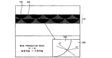
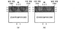
- FIG. 1 is an enlarged sectional view of an interlayer noise reducing hard panel according to the present invention.
- FIG. 3 is a graph supplementing Equation (1) according to the present invention.
- FIG. 5 is a view showing that a sound wave according to the present invention is totally reflected.
- FIG. 6 is a view showing a fixed-end reflection of a sound wave according to the present invention.
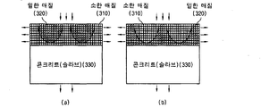
- FIG. 7 is a cross-sectional view of a hard panel in which a pattern layer is formed of the same material according to the present invention.
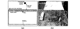
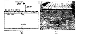
- Figure 8 is a schematic and experimental set-up of the scale model experiment of Figure 7 according to the present invention.
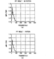
- FIG. 9 is a graph showing FFT (Fast Fourier Transform) results of a sound wave reduction test of a hard panel in which a pattern layer having the same material but different properties according to the present invention is formed.
- FIG. 10 is a cross-sectional view of a hard panel in which a pattern layer is formed of different materials according to the present invention.
- FIG. 11 is a schematic and experimental set-up of the scale model experiment of FIG. 10 according to the present invention.
- FIG. 12 is a graph showing FFT results of acoustic wave reduction experiments of a hard panel in which a pattern layer is formed of different materials according to the present invention.
- FIG. 13 is a sectional view of a hard panel in which a pattern layer according to the present invention is formed of a plurality of layers.
- FIG. 14 is a sectional view of a hard panel in which a pattern layer according to the present invention is formed as a single layer.
- 15 is a cross-sectional view of a hard panel formed with a sound absorbing material according to the present invention.
- 16 is another embodiment of the pattern layer shape according to the present invention.
- 17 is a plan view of a hard panel according to the present invention.
- FIG. 18 is a perspective view of a plurality of hard panels assembled according to the present invention.
- 19 is a perspective view of assembled hard panels of various forms according to the present invention.
- 20 is a bottom view showing a position where the hard panel according to the present invention can be embedded
- the present invention relates to a wall and a floor structure composed of a hard panel capable of reducing the interlayer noise generated by using a material having a different density and elastic modulus, and in which a vertically transmitted sound wave passes through a pattern layer And the sound waves are propagated to the side to increase the moving distance of the sound waves to dissipate the sound wave energy.
- the noise is dissipated by dissipating the sound wave energy through incidence, reflection, refraction, and cancellation of the sound wave.
- the pattern layer of the hard panel is defined as a patterned layer arranged regularly or arbitrarily in a secondary and a three-dimensional manner with different density or elastic modulus in the base layer.
- FIG. 1 is an enlarged cross-sectional view of a base layer of a floor and a floor structure for reducing interlayer noise according to an embodiment of the present invention.
- the horizontal direction of the sound wave WS is converted.
- the traveling direction of the sound wave WS is horizontally converted and to convert the traveling direction of the sound wave WS to the horizontal direction as much as possible, So as to dissipate the horizontally transmitted sound wave WS.
- a part of the sound wave WS is transmitted through the boundary of the medium and a part of the sound wave WS is reflected, thereby increasing the travel distance of the sound wave WS, thereby maximizing the energy dissipation phenomenon.
- the propagation speed of a sound wave (WS) moves from a material having a slow propagation speed to a material having a fast propagation speed or moving from a fast material to a slow material, the larger the difference in the propagation speed, the larger the refraction angle.
- the larger the difference in propagation velocity or acoustic impedance when the sound wave WS travels from the dense medium 320 to the dense medium 310 to the medium 320 that is dense in the medium 310, WS in the pattern layer 100 is not limited thereto.
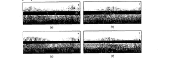
- 2 (a) and 2 (b) are simulations using a von Mises stress contour line.
- 2 (c) and 2 (d) are simulations of the stress in the vertical direction.
- the stress simulation conditions are shown in Table 1.
- FIG. 2 (a) shows that the sound wave WS transferred from the upper part of the hard panel is transmitted to the lower part of the hard panel as it is without refraction due to the von Meister stress distribution of the interlayer acoustic noise wave WS of the hard panel in which the pattern layer is not present
- FIG. 2 (b) shows that the stress concentration is dispersed because the semicircular pattern shown in FIG. 1 is formed in a double pattern
- Fig. 2 (c) is a vertical stress simulation in the absence of a pattern
- Fig. 2 (d) is a vertical stress simulation in the case where a pattern is formed. It is confirmed from this that the sound wave WS transmitted from the upper part of the panel is refracted along the pattern layer 100 so that the transmission direction is horizontally converted or the sound wave WS is scattered or canceled as it passes through the pattern layer 100 have.
- the propagation speed of the sound wave in the medium is defined as follows.
- E is the dynamic modulus of elasticity
- v is the dynamic Poisson's ratio
- p is the density
- Equation (1) is the propagation velocity of the longitudinal wave
- Equation (2) is propagation velocity of the transverse wave. Both longitudinal and transverse propagation velocities are proportional to the dynamic modulus and inversely proportional to density.
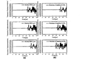
- FIG. 3 is a graph showing the propagation speed of a sound wave, in which transverse displacement is calculated over time.
- the transverse displacement is the amplitude of the sound wave WS and depends on the sound wave WS.
- FIG. 3 (a) it can be seen that as the density increases, the propagation speed is slowed and the arrival time is delayed.
- FIG. 3 (b) it is seen that the propagation speed increases with the increase of the elastic modulus. Accordingly, the propagation velocity increases as the density or the elastic modulus increases as shown in the above equation, and the propagation velocity transmitted from the upper portion of the hard panel 10 is influenced by the elastic modulus and density of the pattern layer 100 formed on the hard panel 10 Can be confirmed.
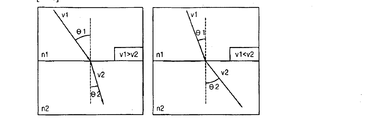
- FIG. 4 shows the transmission of sound waves according to the density of the medium.
- FIG. 4 (a) shows that sound waves are transmitted to the medium densified in the submerged medium
- FIG. 4 (b) shows that the medium is propagated to the submerged medium.
- Equation (3) The relationship between the refractive index (n) and the propagation velocity (v) at two medium interfaces is defined by Snell's law as shown in Equation (3).
- Equation (4) The total reflection condition at this time is expressed by Equation (4).
- the critical angle decreases as the propagation speed difference increases.
- the critical angle is between 30 ° and 65.38 °.
- the sound wave (WS) meets the boundary of the medium at an angle ranging from the critical angle to 90 °, only reflection without transmission occurs. Accordingly, the incident wave and the reflected wave can be offset from each other in the hard panel 10, and the traveling distance of the sound wave WS is increased, and the scattering is increased.
- FIG. 6 shows that a sound wave according to a medium density is fixedly reflected.
- a transmitted sound wave WS is reflected at a boundary of a medium
- the incident wave meets a medium 320 that is more dense than the present, do.
- the reflected wave propagating from the transmitted sound wave WS to the medium 320 pressed by the medium 310 is reflected by the phase shifted by 180 degrees and the transmitted sound wave WS is canceled by the phase inversion, .
- Acoustic Impedance is expressed by Equation (5).
- Acoustic Impedance is used to evaluate acoustic absorption when determining acoustic transmission and reflection at the boundary of two materials with different acoustic impedances.
- the propagation energy decreases in inverse proportion to the distance.
- the incident angle of the sound wave WS incident on the bottom surface of the base layer 200 is less than 90 degrees, the sound wave WS at the bottom boundary surface is not propagated to other medium such as the bottom slab layer, The energy of the noise transmitted to the floor is sharply reduced.
- the present invention uses this principle to extend the propagation path of the sound wave WS by allowing the sound wave WS to be diffracted and scattered by the pattern layer 100 to be incident on the bottom of the base layer 200, The incident angle to the bottom surface of the base layer 200 is 90 degrees or less, thereby reducing the noise.
- the pattern layer 100 and the base layer 200 of the hard panel 10 are formed of the same material, but have different density and elastic modulus.
- FIG. 7 is a cross-sectional view of a hard panel in which a pattern layer and a base layer are formed of the same material.
- the formed pattern layer 100 and the base layer 200 are formed of the same material but have different physical properties. That is, the density and the elastic modulus are formed to be different from each other, and the sound wave WS delivered from above the hard panel 10 is horizontally transmitted by the Snell's law. 7 (a), the sound waves move from the medium to the small medium 310, while the sound waves move from the medium to the medium.
- FIG. 8 (a) is a schematic diagram of a scale model experiment
- FIG. 8 (b) is a set for a lab-scale interlayer noise reduction model experiment with a hard panel 10 in which a pattern layer and a base layer are formed of the same material.
- FIG. 9 is a graph showing the result of sound wave reduction of a hard panel in which a pattern layer and a base layer having the same material but different physical properties are formed, by an FFT (Fast Fourier Transform). The experimental and simulation conditions are shown in Table 2.
- FIG. 9A is a graph showing a noise reduction result obtained by moving a sound wave with a medium pressed in a low frequency medium
- FIG. 9A is a graph showing a noise reduction result obtained when a sound wave has no pattern (no hard disk 10 including a pattern layer and a base layer)
- FIG. 9 (b) is a graph showing the energy of a sound wave according to the FFT (Fast Fourier Transform), and FIG. 9 (b) shows a hard panel 10 including a pattern layer and a base layer when a pattern exists) Fast Fourier Transform).
- FFT Fast Fourier Transform
- the base layer 200 of the hard panel 10 and the material of the pattern layer 100 are formed differently.
- 10 is a cross-sectional view of a hard panel in which a pattern layer and a base layer are formed of materials having different materials, and the materials, the density, and the modulus of elasticity of the formed pattern layer and the base layer are different from each other. And horizontally transmits the sound wave WS delivered from above the hard panel 10 according to the Snell's law. 10 (a) moves from a medium in which the sound waves WS are concentrated to a medium in which the sound waves are concentrated, and FIG. 10 (b) moves to a medium in which the sound waves WS are concentrated in the medium.
- FIG. 11 (a) is a schematic diagram of a scale model test
- FIG. 11 (b) shows a hard panel 10 in which a pattern layer and a base layer are formed of different materials.
- FIG. 12 is a graph showing the result of sound wave reduction of a hard panel in which a pattern layer and a base layer are formed of different materials by FFT (Fast Fourier Transform).
- FIG. 12B is a graph showing the energy (with the hard panel 10 including the pattern layer and the base layer) energy when the pattern is present is FFT (Fast Fourier Transform) (Fast Fourier Transform).
- FFT Fast Fourier Transform
- the pattern layer and the base layer are formed of materials having different materials, density and elastic modulus as compared with Example 1 and Example 2, the larger the difference between the propagation velocity and the acoustic impedance, The reduction effect is large.
- the pattern layer 100 of the hard panel 10 may be formed of a single layer or a plurality of layers.
- Fig. 13 is a sectional view of a hard panel in which a pattern layer is formed of a plurality of layers
- Fig. 14 is a sectional view of a hard panel in which a pattern layer is formed in a single layer.
- a semi-circular pattern is formed in a plurality of layers, and the thickness of the hard panel 10 is 1 cm.
- the pattern is formed as a single layer with a semi-circular pattern.
- the single layered hard panel 10 is effective in sound wave refraction and reflection, and both the single layer and the multiple layers have a sound wave refraction and reflection effect, It is not limited to the number.
- a sound absorbing material 400 may also be formed inside the hard panel 10.
- the sound absorbing material 400 absorbs the sound waves WS to promote the noise reduction effect.
- the sound absorbing material 400 may be made of glass fiber, sponge, or the like, and is not limited to the material.
- the pattern layer 100 of the hard panel 10 may be formed in various forms.
- FIG. 16 shows an embodiment in the form of a hard panel including a pattern layer, wherein at least one or two or more materials are combined to form an inverted triangle, a right triangle, an ellipse, a wavy pattern, etc. in addition to the semicircular pattern layer 100 .
- the material forming the pattern layer and the base layer of the hard panel 10 may be selected from the group consisting of PVC, aluminum, ABS resin, polylactic acid (PLA), metal, fiber, rubber or sound wave
- PVC polyvinyl chloride
- PLA polylactic acid
- the material can be manufactured by a variety of methods including materials capable of imparting difference in propagation speed and acoustic impedance of a sound wave (WS) by density and elastic modulus.
- WS sound wave
- the hard panel 10 can be manufactured by manufacturing a mold.
- 17 is a plan view of a rectangular hard panel, in which an adhesive 500 is applied between the hard panel 10 and the hard panel 10 to absorb the horizontally converted noise, thereby promoting the noise reduction effect.
- the hard panel 10 may be manufactured by fixing with an adhesive 500 and a hook.
- the hard panel 10 can be cured by using the upper mold in the construction method using the hard panel 10 of the wall and bottom structure for reducing the interlayer noise.
- Fig. 18 is a perspective view of a plurality of hard panels assembled.
- Fig. 18 (a) is an embodiment in which a joint portion of a hard panel is tiled
- Fig. 18 (b) is an example in which a joint portion is staggered As an example, it can be installed appropriately according to the construction site.
- FIG. 19 is a perspective view of assembled hard panels of various forms according to the present invention, showing an arrangement of the hard panel 10 in the form of a square triangle or a polygon, and may be appropriately installed according to the construction site.
- FIG. 20 is a bottom view showing a position where the hard panel according to the present invention can be embedded, showing a position where the hard panel 10 can be embedded.
- the interlayer noise reducing wall and floor panel hard panel according to the present invention can be buried when a bottom acoustic wave (WS) of a new building or building is installed.
- the hard panel 10 may be included in the concrete slab layer 330, the lightweight foamed concrete layer, and the finished mortar layer at the time of embedding.
- the connection between the hard panel 10 and the hard panel 10 can be performed using an adhesive 500 or the like.
- the adhesive 500 silicone, epoxy resin, mortar, or the like may be used.
- the adhesive 500 may be connected using a connecting hook without using the adhesive 500.
- the present invention can be applied not only to the floor of the building but also to the wall 72 or the like so that it can be used as a soundproofing material or as a noise reduction material. .
- the thickness of the hard panel 10 is preferably about 4 mm to 50 mm. It can be manufactured in 4 mm, which is similar to the general thickness of general flooring. It is featured to increase space utilization, and to be easy to carry and install. Also, it is possible to control various thicknesses and the number of pattern layers according to the place and purpose of installation, and it is preferable that various patterns can be mixed and manufactured.
- the hard panel 10 includes a concrete slab 330, a lightweight foamed concrete 630, a finishing mortar 620 and a floor finishing layer 610 when the hard panel 10 is embedded in the floor of existing and new buildings. As shown in FIG. In addition, when the hard panel 10 is embedded in the floor of the existing and new construction, the hard panel 10 includes a concrete slab 330, a lightweight foamed concrete 630, a closed mortar 620, 610). ≪ / RTI > The hard panel 10 may be installed as an external flooring on the floor of existing and new construction. In addition, the hard panel 10 can be installed as a floor structure of existing and new buildings, and the hard panel 10 can be installed as a wall structure of existing and new buildings.
Landscapes
- Engineering & Computer Science (AREA)
- Architecture (AREA)
- Physics & Mathematics (AREA)
- Civil Engineering (AREA)
- Structural Engineering (AREA)
- Acoustics & Sound (AREA)
- Electromagnetism (AREA)
- Building Environments (AREA)
Abstract
본 발명은 층간소음 저감용 벽체 및 바닥 구조의 하드패널에 관한 것으로서, 더욱 상세하게는 밀도와 탄성계수가 서로 다른 재료를 이용하여 패턴을 형성한 패널로, 상층으로부터 전달된 음파가 패턴층을 통과하면서 전달경로가 수평적으로 변환되고 음파의 입사 및 반사, 굴절, 상쇄를 통하여 음파 에너지를 소산시켜 소음을 저감하는 것에 관한 것이다. 본 발명에 따른 층간소음 저감용 벽체 및 바닥 구조의 하드패널은 경량 및 중량충격음을 효과적으로 저감시킬 수 있고, 소음을 굴절 또는 반사시키기 위해 하드패널 내의 패턴층을 복수개 및 단수개의 층으로 형성하여 효과적으로 소음을 소산시킬 수 있다. 또한, 하드패널을 통과한 소음을 흡수할 수 있는 흡음재가 형성되어 소음을 효과적으로 저감시킬 수 있으며, 기존 및 신축 건축물에 적용이 용이하여 비용절감의 효과가 있다.
Description
본 발명은 층간소음 저감용 벽체 및 바닥 구조에 관한 것으로서, 더욱 상세하게는 밀도와 탄성계수가 서로 다른 재료를 이용하여 패턴층을 형성한 패널로, 음파의 전달 방향을 바꾸고 음파 에너지를 소산시켜 벽체 및 바닥구조에서 소음을 저감하는 기술에 관한 것이다.
급격한 도시화로 우리나라 전체 국민의 대다수가 공동주택에 거주하기 때문에 외국에 비해 상대적으로 층간소음 문제가 많고 공동주택에서 발생하는 층간소음 분쟁으로 갈등이 심화하여 사회적인 이슈로 제기되고 있다.
층간소음 중 바닥충격음은 충격특성에 따라 경량충격음과 중량충격음으로 구분된다. 경량충격음은 식탁을 끌거나 마늘 찧는 소리, 물건이 떨어지는 소리 등으로서 가볍고 딱딱한 소리로 58dB이하의 고음역 소리로서, 충격력이 약하고 음향 지속시간이 짧은 특성이 있다. 중량충격음은 아이들의 뛰는 소리나 발자국 소리 등으로서 무겁고 큰 저음역의 소리로서, 충격력이 크고 음향 지속시간이 길다는 물리적 특징을 가지고 있어 대표적인 분쟁의 원인으로 저감시키기 어려운 문제점이 있다.
층간소음 문제를 해결하기 위하여 바닥면에 섬유계매트, 고무계매트 또는 다공성수지매트 등의 충격흡수소재를 사용하거나, 바닥면으로부터 이격시킨 뜬 바닥구조방법이 주로 사용된다.
하지만 이러한 충격흡수소재나 뜬 바닥구조방법은 경량충격음은 54%정도 효과적으로 저감이 가능하지만, 중량충격음은 효과가 8%정도로 저감하기에는 한계가 있다.
국토부는 앞으로 층간소음 저감 측면에서 가장 적합한 구조형식의 기둥식구조를 바탕으로 층간소음 해법을 새로 지어질 아파트에 적용 예정이지만, 이러한 구조는 상대적으로 시공비가 고가이며, 새로 지어지는 공동주택에만 적용되는 만큼 기존 아파트에 대한 대책이 필요하다.
종래의 기술로서 특허문헌 1에 요철이 형성된 판지 사이에 에어로겔을 형성하여 단열성, 방음성, 흡음성, 방진성 및 오염물질 흡착성에 효과가 있는 건축용 자재를 제시하고 있다. 판지 사이에 나노 다공성 구조를 갖는 에어로겔은 반투명한 극저밀도의 첨단소재로서, 효율적인 단열 재료이다. 바닥재는 난방과 밀접한 연관이 있기 때문에 단열효과가 있는 에어로겔로 형성된 특허문헌 1은 바닥재로서 부적합하다. 또한 미세기공이 많은 판지 사이에 에어로겔을 넣는 것이기 때문에 재료에 한정적이고, 에어로겔은 고가의 재료이기 때문에 실현가능성이 낮기 때문에 방음을 목적으로 바닥에 설치하는 바닥재로서는 부적합하다.
* 선행기술문헌
* 특허문헌
1. 한국 공개특허 제10-2013-0122407호
본 발명은 상기와 같은 문제점을 해결하고자 경량 및 중량충격음을 효과적으로 저감시킬 수 있는 층간소음 저감용 벽체 및 바닥구조를 제공하는 것을 목적으로 한다.
상기의 해결하고자 하는 과제를 위한 본 발명에 따른 층간소음 저감용 벽체 및 바닥구조는 하드패널로 구성되며, 하드패널 내의 매질에서 음파의 전파속도 차이가 발생하도록 베이스층 내에 패턴화된 층이 형성된 것을 특징으로 한다.
본 발명의 바람직한 실시예로서, 상기 패턴화된 층과 상기 베이스층의 경계면에서 수직으로 입사된 음파가 굴절이 되어 수평으로 전파되는 것을 특징으로 한다.
본 발명의 바람직한 실시예로서, 상기 패턴화된 층과 상기 베이스층의 경계면에서 입사된 음파가 굴절되어 음파의 이동거리를 증가시켜 음파 에너지를 소산시키는 것을 특징으로 한다.
본 발명의 바람직한 실시예로서, 상기 패턴화된 층과 상기 베이스층의 경계면에서 입사된 음파가 전반사되어 위상반전되면서 입사파와 상쇄되는 것을 특징으로 한다.
본 발명의 바람직한 실시예로서, 상기 패턴화된 층과 상기 베이스층의 전파속도 비가 적어도 1보다 큰 것을 특징으로 한다.
본 발명의 바람직한 실시예로서, 상기 패턴화된 층과 상기 베이스층의 음향 임피던스(Acoustic Impedance) 비가 적어도 1보다 큰 것을 특징으로 한다.
본 발명의 바람직한 실시예로서, 상기 패턴화된 층은 매질의 재료가 상기 베이스층과 다른 것을 특징으로 한다.
본 발명의 바람직한 실시예로서, 상기 패턴화된 층은 매질의 재료가 상기 베이스층과 같으나 밀도가 서로 다른 것을 특징으로 한다.
본 발명의 바람직한 실시예로서, 상기 패턴화된 층은 매질의 재료가 상기 베이스층과 같으나 탄성계수가 서로 다른 것을 특징으로 한다.
본 발명의 바람직한 실시예로서, 상기 패턴화된 층은 반원 또는 다각형 형상인 것을 특징으로 한다.
본 발명의 바람직한 실시예로서, 상기 패턴화된 구조의 매질 밀도가 베이스층보다 큰 것을 특징으로 한다.
본 발명의 바람직한 실시예로서, 상기 패턴화된 구조의 매질 밀도가 베이스층보다 작은 것을 특징으로 한다.
본 발명의 바람직한 실시예로서, 상기 패턴화된 구조의 매질 탄성계수가 베이스층보다 큰 것을 특징으로 한다.
본 발명의 바람직한 실시예로서, 상기 패턴화된 구조의 매질 탄성계수가 베이스층보다 작은 것을 특징으로 한다.
본 발명의 바람직한 실시예로서, 상기 패턴화된 층은 단층 또는 적어도 2개의 층으로 형성된 것을 특징으로 한다.
본 발명의 바람직한 실시예로서, 상기 매질의 재료는 PVC, 알루미늄, ABS 수지, PLA, 금속, 섬유, 고무 및 콘크리트, 모르타르에서 선택된 하나 또는 2 이상의 조합인 것을 특징으로 한다.
본 발명의 바람직한 실시예로서, 상기 패턴화된 층 사이에 흡음재를 추가한 것을 특징으로 한다.
본 발명의 바람직한 실시예로서, 층간소음 저감용 벽체 및 바닥 구조의 하드패널을 제조하는 방법에 있어서, 상기 하드패널은 3D 프린터로 제작하는 것을 특징으로 한다.
본 발명의 바람직한 실시예로서, 층간소음 저감용 벽체 및 바닥 구조의 하드패널을 제조하는 방법에 있어서, 상기 하드패널은 거푸집(mold)를 제작하여 서로 다른 물성치를 갖는 재료의 배합으로 제작하는 것을 특징으로 한다.
본 발명의 바람직한 실시예로서, 층간소음 저감용 벽체 및 바닥 구조의 하드패널을 사용한 시공방법에 있어서, 상기 하드패널은 4각형 매트 및 타일 타입으로 형성하고, 상기 하드패널과 하드패널 사이 및 하드패널내 구성재료들 사이를 접착제를 사용하여 접착하는 것을 특징으로 한다.
본 발명의 바람직한 실시예로서, 기존 건축물의 바닥에 바둑판 형태 또는 지그재그 배열 형태로 상기 하드패널을 조합하여 설치하는 것을 특징으로 한다.
본 발명의 바람직한 실시예로서, 신축 건축물의 콘크리트 타설 시 상기 하드패널을 매립하여 설치하는 것을 특징으로 한다. 콘크리트 슬래브 층, 경량기포콘크리트 층, 마감모르타르 층 중 어떠한 층에도 매립이 가능하다는 것을 특징으로 한다.
본 발명의 바람직한 실시예로서, 층간소음 저감용 벽체 및 바닥 구조의 하드패널은 벽체 또는 바닥에 설치하는 것을 특징으로 하되, 이에만 국한되지 않을 것을 특징으로 한다.
본 발명의 다른 실시예로서, 일측에서 입사되는 소음이 바닥으로 전달될 때 패널의 측방향으로 상기 소음의 음파가 굴절이나 비산되도록 일측이 넓고 타측이 좁은 반구 또는 각뿔 형태를 가지는 패턴층 및 상기 패턴층의 타측 및 측면을 감싸며, 상기 패턴층에서 전달되는 소음의 전달 경로를 연장시켜 바닥으로 전달되는 소음을 저감시키는 베이스층을 포함하는 것을 특징으로 한다.
예시적인 실시예에 있어서, 층간소음 저감용 벽체 및 바닥 구조의 하드패널을 제조방법에서 상기 하드패널은 몰드를 제작하여 제조될 수 있다.
예시적인 실시예에 있어서, 상기 하드패널은 접착제 및 후크로 고정하여 제작될 수 있다.
예시적인 실시예에 있어서, 층간소음 저감용 벽체 및 바닥 구조의 하드패널을 사용한 시공방법에서 하드패널은 상부거푸집을 이용하여 양생될 수 있다.
예시적인 실시예에 있어서, 기존 및 신축 건축물의 바닥 안에 상기 하드패널을 매립하여 설치할 수 있다.
예시적인 실시예에 있어서, 기존 및 신축 건축물의 바닥 안에 상기 하드패널을 매립하는 경우, 상기 하드패널은 콘크리트 슬래브, 경량기포콘크리트, 마감 모르타르 및 바닥 마감재 층의 사이에 설치될 수 있다.
예시적인 실시예에 있어서, 기존 및 신축 건축물의 바닥 안에 상기 하드패널을 매립하는 경우, 상기 하드패널은 콘크리트 슬래브, 경량기포콘크리트, 마감 모르타르 및 바닥 마감재 층 중 하나에 포함되어 설치될 수 있다.
예시적인 실시예에 있어서, 기존 및 신축 건축물의 바닥 위에 상기 하드패널을 외장형 바닥재로서 설치할 수 있다.
예시적인 실시예에 있어서, 기존 및 신축 건축물의 바닥구조로서 상기 하드패널을 설치할 수 있다.
예시적인 실시예에 있어서, 기존 및 신축 건축물의 벽체구조로서 상기 하드패널을 설치할 수 있다.
본 발명에 따른 층간소음 저감용 벽체 및 바닥 구조의 하드패널은 경량 및 중량충격음을 효과적으로 저감시킬 수 있다.
또한, 소음을 저감시키기 위한 음파의 굴절 및 반사를 위해 하드패널 내의 패턴층을 단수개 혹은 복수개의 층으로 형성하여 효과적으로 소음을 소산시킬 수 있다.
또한, 하드패널을 통과한 소음을 흡수할 수 있는 흡음재가 형성되어 소음을 효과적으로 저감시킬 수 있다
또한, 기존 건축물에 적용이 가능하여 비용절감의 효과가 있다.
또한, 적은 시공비라는 장점을 갖고 있어 경제적인 효과가 있다.
도 1은 본 발명에 따른 층간소음 저감 하드패널의 확대단면도.
도 2는 본 발명에 따른 음파 전달 시뮬레이션의 분석도.
도 3은 본 발명에 따른 수학식 1을 보완한 그래프.
도 4는 본 발명에 따른 음파전달을 나타낸 도면.
도 5는 본 발명에 따른 음파가 전반사 되는 것을 나타낸 도면.
도 6은 본 발명에 따른 음파가 고정단 반사되는 것을 나타낸 도면.
도 7은 본 발명에 따른 서로 같은 재료로 패턴층이 형성된 하드패널의 단면도.
도 8은 본 발명에 따른 도 7의 축소모형 실험 개략도 및 실험 설정도.
도 9은 본 발명에 따른 같은 재료이지만 물성치가 서로 다른 패턴층이 형성된 하드패널의 음파 저감 실험결과를 FFT(Fast fourier Transform)로 나타낸 그래프.
도 10은 본 발명에 따른 서로 다른 재료로 패턴층이 형성된 하드패널의 단면도.
도 11은 본 발명에 따른 도 10의 축소모형 실험 개략도 및 실험 설정도.
도 12는 본 발명에 따른 서로 다른 재료로 패턴층이 형성된 하드패널의 음파 저감 실험결과를 FFT로 나타낸 그래프.
도 13은 본 발명에 따른 패턴층이 복수개의 층으로 형성된 하드패널의 단면도.
도 14는 본 발명에 따른 패턴층이 단층으로 형성된 하드패널의 단면도.
도 15은 본 발명에 따른 흡음재가 형성된 하드패널의 단면도.
도 16은 본 발명에 따른 패턴층 모양의 또 다른 실시예.
도 17은 본 발명에 따른 하드패널의 평면도.
도 18은 본 발명에 따른 복수개의 하드패널을 조립한 사시도.
도 19는 본 발명에 따른 다양한 형태의 하드패널을 조립한 사시도.
도 20은 본 발명에 따른 하드패널이 매립될 수 있는 위치를 나타낸 바닥구조도.
이하 본 발명의 실시를 위한 구체적인 실시예를 도면을 참고하여 설명한다. 본 발명의 실시예는 하나의 발명을 설명하기 위한 것으로서 권리범위는 예시된 실시예에 한정되지 아니하고, 예시된 도면은 발명의 명확성을 위하여 핵심적인 내용만 확대 도시하고 부수적인 것을 생략하였으므로 도면에 한정하여 해석하여서는 아니 된다.
본 발명은 밀도와 탄성계수가 서로 다른 재료를 이용하여 패턴층이 형성된 층간소음을 저감시킬 수 있는 하드패널로 구성된 벽체 및 바닥구조에 관한 것으로서, 수직으로 전달된 음파가 패턴층을 통과하면서 수평적으로 굴절 변환되어 측면으로 음파를 전달하면서 음파의 이동거리를 증가시켜 음파에너지를 소산시키는 원리를 이용한 것으로서, 음파의 입사 및 반사, 굴절, 상쇄를 통하여 음파 에너지를 소산시켜 소음을 저감하는 것이다.
본 발명에서 하드패널의 패턴층은 베이스층 내에서 밀도나 탄성계수를 달리하여 2차 및 3차원적으로 규칙적으로 또는 임의로 배열되어 패턴화된 층으로 정의한다.
도 1은 본 발명에 따른 층간소음 저감용 벽체 및 바닥 구조의 베이스층 확대단면도로서, 수직으로부터 전달된 음파에너지가 패턴화된 매질을 통과하면서 매질에 따른 전파속도 또는 음향 임피던스(Acoustic Impedance) 차이를 바탕으로 음파(WS)의 진행 방향을 수평적으로 변환시킨다. 음파(WS)의 굴절현상을 이용하여 음파(WS)의 진행방향이 수평적으로 변환됨에 따라 하부로 전달되는 소음을 저감하고 음파(WS)의 진행방향을 최대한 수평적으로 변환시켜 음파(WS)의 이동거리를 증가시킴에 따라 수평적으로 전달되는 음파(WS)를 소산시킨다.
또한, 매질의 경계에서 음파(WS)의 일부는 투과하고 또 다른 일부는 반사되어 음파(WS)의 이동거리를 증가시킬 수 있어 에너지 소산현상을 극대화할 수 있다. 음파(WS)는 전파속도가 느린 물질에서 전파속도가 빠른 물질로 이동하거나 빠른 물질에서 느린 물질로 이동할 때 전파속도의 차이가 클수록 굴절각이 크다. 따라서 음파(WS)가 밀한 매질(320)에서 소한 매질(310)로, 소한 매질(310)에서 밀한 매질(320)로 이동할 때 전파속도 또는 음향 임피던스(Acoustic Impedance) 차이가 클수록 바람직하며, 음파(WS)의 패턴층(100) 통과 순서는 이에 한정하지 않는다.
도 2는 패턴층 유무에 따른 음파 전달 시뮬레이션의 분석도로서, 도 2(a)와 도 2(b)는 폰 미제스 응력(von Mises stress) 등고선을 이용한 시뮬레이션으로 중량충격음의 수치가 피크일 때 응력분포를 시뮬레이션 한 것이고, 도 2(c)와 2(d)는 수직방향 응력 시뮬레이션한 것이다. 응력 시뮬레이션 조건은 표 1과 같다.
도 2의 (a)는 패턴층이 존재하지 않는 하드패널의 층간소음 음파(WS)의 폰 미제스 응력분포로 하드패널 상부로부터 전달받은 음파(WS)가 굴절 없이 그대로 하드패널 하부로 전달되는 것을 보이고, 도 2의 (b)는 도 1과 같은 반원형태의 패턴이 이중으로 형성된 것으로 응력집중이 분산되는 것을 보여준다. 도 2의 (c)는 패턴이 없는 경우의 수직방향 응력 시뮬레이션이고, 도 2의 (d)는 패턴이 형성된 경우의 수직방향 응력 시뮬레이션이다. 이로부터 패널 상부로부터 전달받은 음파(WS)가 패턴층(100)을 따라 굴절되어 전달방향이 수평적으로 변환되거나, 음파(WS)가 패턴층(100)을 통과하면서 소산되거나 상쇄되는 것을 확인할 수 있다.
표 1 
매질 내의 음파 전파속도는 다음과 같이 정의된다.
수학식 1 
수학식 2 
여기서, E는 동탄성계수이고, v는 동포아송 비이며, p는 밀도를 나타낸다.
수학식 1은 종파의 전파속도이며, 수학식 2는 횡파의 전파속도이다. 종파와 횡파 전파속도는 모두 동탄성계수에 비례하고 밀도에는 반비례한다.
도 3은 음파의 전파속도를 보여주는 그래프로서, 횡단변위(transverse displacement)를 시간에 따라 계산한 것이다. 횡단변위는 음파(WS)의 진폭(amplitude)으로 음파(WS)에 따라 달라진다.
도 3(a)에서는 밀도가 증가하면서 전파속도가 느려져 도착시간(arrival time)이 늦어지는 것을 확인할 수 있으며, 도 3(b)에서는 탄성계수가 증가하면서 전파속도가 빨라지는 것을 알 수 있다. 따라서 상기 수학식과 같이 밀도가 작거나 탄성계수가 클수록 전파속도가 증가하며, 하드패널(10) 상부로부터 전달 받은 전파속도는 하드패널(10)에 형성된 패턴층(100)의 탄성계수와 밀도에 영향이 있음을 확인할 수 있다.
도 4는 매질 밀도에 따른 음파전달을 나타낸 도면으로서, 도 4(a)는 소한 매질에서 밀한 매질로 음파가 전달되는 것을 나타내고, 도 4(b)는 밀한 매질에서 소한 매질로 전파되는 것을 나타낸다.
2개의 매질 경계면에서 굴절율(n)과 전파속도(v)의 관계는 스넬의 법칙으로 수학식 3과 같이 정의된다.
수학식 3 
스넬의 법칙으로부터 음파(WS) 전달시 매질의 경계에서 음파(WS)가 굴절할 도가 빠른 물질(소한 매질(310))로 이동하거나, 전파속도가 빠른 물질(소한 매질(310))에서 전파속도가 느린 물질(밀한 매질(320))로 이동할 때, 전파속도 차이가 클수록 굴절각이 크다. 이러한 특징을 바탕으로 음파(WS)의 이동거리를 증가시켜 음파에너지를 소산시킨다. 음파(WS)의 굴절각은 음파(WS)가 진행하는 매질과 매질 사이의 전파속도차이  를 크게 할수록
  굴절각의 비례관계이므로 굴절각이 커진다.
도 5는 매질 밀도에 따른 음파가 전반사되는 것을 나타낸 도면으로서, 음파(WS)가 굴절률이 큰 매질(밀한 매질(320))에서 굴절률이 작은 매질(소한 매질(310))로 진행할 때, 입사각이 임계각  보다 클 경우 경계면에서 전부 반사된다. 이때의 전반사 조건은 수학식 4와 같다.
수학식 4 
전달된 음파(WS)가 밀한 매질(320)에서 소한 매질(310)로 진행할 때, 전파속도차이 가 클수록 임계각이 작아진다.
전파속도차이의 범위를 최소 1.1에서 최대 2.0이라고 가정한다면, 임계각은 30°~ 65.38°가 된다. 이때 음파(WS)가 매질의 경계에서 임계각 에서 90°까지 범위의 각도로 만나면 투과 없이 반사만 일어나게 된다. 이에 따라 하드패널(10) 내에서 입사파와 반사파가 서로 상쇄될 수 있고, 음파(WS)의 진행거리가 증가되어 소산이 증대된다.
도 6은 매질 밀도에 따른 음파가 고정단 반사되는 것을 나타낸 도면으로서, 전달된 음파(WS)가 매질의 경계에서 반사가 일어날 때, 입사파가 현재보다 밀한 매질(320)을 만나면 위상이 바뀌어 반사된다. 따라서 전달된 음파(WS)가 소한 매질(310)에서 밀한 매질(320)로 진행하다가 반사되는 반사파는 위상이 180°만큼 변하며 전달된 음파(WS)는 위상 반전으로 인하여 상쇄되어 상대적으로 투과파가 저감된다.
전달된 음파(WS)는 전파속도 또는 음향 임피던스(Acoustic Impedance) 차이가 클수록 굴절각이 커지기 때문에 보다 큰 저감을 가능하게 한다. 음향 임피던스(Acoustic Impedance)는 수학식 5와 같다.
수학식 5 
여기서, Z는 음향 임피던스(Acoustic Impedance), p는 밀도, V는 음향 속도를 나타낸다. 음향 임피던스(Acoustic Impedance)는 다른 음향 임피던스를 가진 두 물질의 경계에서 음향 투과 및 반사의 결정을 할 때, 음향 흡수를 평가할 때 사용된다.
일반적으로 전달경로가 길어지면 길어질수록 거리에 반비례하여 전파에너지가 줄어들게 된다. 특히 베이스층(200)의 바닥면에 입사되는 음파(WS)의 입사각이 90°이하가 되면, 바닥 경계면에서의 음파(WS)가 바닥 슬라브층 등의 타매질로 전파되기보다는 하드패널(10)의 베이스층(200) 내로 반사되어 바닥으로 전달되는 소음의 에너지가 급격하게 줄어들게 된다. 본 발명은 이러한 원리를 이용하여 패턴층(100)에 의해 음파(WS)가 회절 및 비산되어 베이스층(200) 바닥에 입사되도록 함으로써 음파(WS)의 전달 경로를 연장시켜주고, 음파(WS)가 베이스층(200)의 바닥면으로 입사되는 입사각이 90°이하가 되도록 함으로써 소음을 저감할 수 있는 기술이다.
<실시예 1>
본 발명에 따른 일 실시예로서, 하드패널(10)의 패턴층(100) 및 베이스 층(200)을 같은 재료로 형성하되, 밀도와 탄성계수가 서로 다르게 형성한다.
도 7은 서로 같은 재료로 패턴층 및 베이스 층이 형성된 하드패널의 단면도로서, 형성된 패턴층(100) 및 베이스 층(200)이 서로 같은 재료이지만 물성치가 다르게 형성된다. 즉, 밀도와 탄성계수가 서로 다르게 형성하여 상기 스넬의 법칙에 의하여 하드패널(10) 상부로부터 전달된 음파(WS)를 수평적으로 전달시킨다. 도 7(a)는 음파가 밀한 매질에서 소한 매질(310)로 이동하고, 도 7(b)는 음파가 소한 매질에서 밀한 매질로 이동한다.
도 8(a)는 축소모형 실험 개략도이며, 도 8(b)는 서로 같은 재료로 패턴층 및 베이스 층이 형성된 하드패널(10)로 연구실 규모의 층간소음 축소모형 실험을 위한 실제 설정한 것이다.
도 9는 같은 재료이지만 물성치가 서로 다른 패턴층 및 베이스 층이 형성된 하드패널의 음파 저감 결과를 FFT(Fast Fourier Transform)로 나타낸 그래프로서, 실험 및 시뮬레이션 조건은 표 2와 같다.
도 9는 소한매질에서 밀한매질로 음파의 이동을 통한 소음 저감결과 그래프로서, 도 9(a)는 음파가 패턴이 없을 때의(패턴층 및 베이스 층을 포함한 하드패널(10) 없음) 주파수에 따른 음파의 에너지를 FFT(Fast Fourier Transform)로 나타낸 그래프이고, 도 9(b)는 패턴이 있을 때의 패턴층 및 베이스 층을 포함한 하드패널(10) 있음) 주파수에 따른 음파의 에너지를 FFT(Fast Fourier Transform)로 나타낸 그래프이다.
표 2
| 구분 | 재질 | 밀도 ( | 동탄성계수 (GPa) |
| 매질1 | 모르타르(Mortar) | 2.32 | 27.13 |
| 매질2 | 모르타르(Mortar) | 1.95 | 16.01 |
도 9(a)와 도 9(b)를 비교하였을 때, 패턴이 형성된 도 9(b)의 그래프의 에너지가 현저하게 줄어든 것을 확인 할 수 있으며, 패턴에 따라서 패턴 매질 통과순서가 다르게 형성될 수 있다.
<실시예 2>
본 발명에 따른 일 실시예로서, 하드패널(10)의 베이스층(200)과 패턴층(100)의 재료를 서로 다르게 형성한다.
도 10은 재료가 서로 다른 재료로 패턴층 및 베이스 층이 형성된 하드패널의 단면도로서, 형성된 패턴층 및 베이스 층의 재료, 밀도 및 탄성계수를 서로 다르게 형성한다. 상기 스넬의 법칙에 의하여 하드패널(10) 상부로부터 전달된 음파(WS)를 수평적으로 전달시킨다. 도 10(a)은 음파(WS)가 밀한 매질에서 소한 매질로 이동하고, 도 10(b)은 음파(WS)가 소한 매질에서 밀한 매질로 이동한다.
도 11(a)은 축소모형 실험 개략도이며, 도 11(b)은 서로 다른 재료로 패턴층 및 베이스 층이 형성된 하드패널(10)로 연구실 규모의 층간소음 축소모형 실험을 위한 실제 설정한 것이다.
도 12는 서로 다른 재료로 패턴층 및 베이스 층이 형성된 하드패널의 음파 저감 결과를 FFT(Fast Fourier Transform)로 나타낸 그래프로서, 도 12(a)는 패턴이 없을 때의(패턴층 및 베이스 층을 포함한 하드패널(10) 없음) 에너지를 FFT(Fast Fourier Transform)로 나타낸 그래프이고, 도 12(b)는 패턴이 있을 때의(패턴층 및 베이스 층을 포함한 하드패널(10) 있음) 에너지를 FFT(Fast Fourier Transform)로 나타낸 것이다. 실험 및 시뮬레이션 조건은 표 3과 같다.
표 3
| 구분 | 재질 | 밀도 ( | 동탄성계수 (GPa) |
| 매질1 | MC Nylon | 1.15 | 9.48 |
| 매질2 | ABS | 1.04 | 3.63 |
도 12(a)와 도 12(b)를 비교하였을 때, 패턴이 형성된 도 12(b)의 그래프의 에너지가 현저하게 줄어든 것을 확인 할 수 있으며, 상기 스넬의 법칙에 따라 전파속도 또는 음향 임피던스(Acoustic Impedance)차이가 크면 클수록 더욱 저감 효과가 증가함을 알 수 있다.
또한, 실시예 1과 실시예 2를 비교하였을 때 재료, 밀도 및 탄성계수가 다른 물질로 패턴층 및 베이스 층이 형성되었을 때, 전파속도 및 음향 임피던스(Acoustic Impedance) 차이가 클수록 음파(WS)의 저감 효과가 큼을 알 수 있다.
<실시예 3>
본 발명에 따른 일 실시예로서, 하드패널(10)의 패턴층(100)을 단수층 또는 복수의 층으로 형성할 수 있다.
도 13은 패턴층이 복수의 층으로 형성된 하드패널의 단면도이고, 도 14는 패턴층이 단층으로 형성된 하드패널의 단면도이다.
도 13의 복수층패턴 하드패널의 시뮬레이션 조건은 표 4와 같다.
표 4
| 구분 | 재질 | 밀도 ( | 동탄성계수 (GPa) |
| 매질1 | PVC | 1.26 | 2.8 |
| 매질2 | ABS | 1.50 | 9.8 |
패턴은 반원형태의 패턴이 복수층으로 형성되었으며, 하드패널(10)의 두께는 1cm이다.
도 14의 단수층패턴 하드패널의 시뮬레이션 조건은 표 5와 같다.
표 5
| 구분 | 재질 | 밀도 ( | 동탄성계수 (GPa) |
| 매질1 | PVC | 1.26 | 2.8 |
| 매질2 | ABS | 1.50 | 9.8 |
패턴은 반원형태의 패턴이 단수층으로 형성되다.
단수층과 복수층의 음파굴절 및 반사효과를 비교하였을 때 단층패턴 하드패널(10)이 음파굴절 및 반사가 효과적이며, 단수층과 복수층 모두 음파굴절 및 반사효과가 있으므로, 패턴층(100) 개수에 한정하지 않는다.
<실시예 4>
본 발명에 따른 일 실시예로서, 하드패널(10) 내부에 흡음재(400) 또한 형성할 수 있다.
도 15는 흡음재가 형성된 하드패널의 단면도이며, 하드패널(10) 내에 패턴층(100) 사이에 흡음재(400)를 형성하여 하드패널(10) 내의 패턴층(100)을 통과한 음파(WS)를 흡음재(400)로 음파(WS)를 흡수하여 소음저감 효과를 촉진하는 것이 바람직하다. 흡음재(400)는 유리섬유, 스펀지 등을 사용할 수 있으며 재료를 한정하지 않는다.
<실시예 5>
본 발명에 따른 일 실시예로서, 하드패널(10)의 패턴층(100)은 여러 형태로 형성될 수 있다.
도 16은 패턴층이 포함된 하드패널 모양의 실시예로서, 적어도 하나 또는 두 가지 이상의 재료를 조합하여, 상기 반원형상 패턴층(100) 외에 역삼각형, 직각삼각형, 타원형, 물결형 등으로 형성할 수 있다.
<실시예 6>
본 발명에 따른 일 실시예로서, 하드패널(10)의 패턴층 및 베이스 층을 형성하는 재료는 PVC, 알루미늄, ABS 수지, PLA(polylactic acid), 금속, 섬유, 고무 또는 음파(WS), 모르타르 등을 조합하여 패턴층 및 베이스 층을 형성하며, 패널 제조방법으로는 몰드를 제작하여 패널을 제조하는 방법, 재료를 가공하여 일반적인 패널을 제작하는 방법으로 제조하는 방법, PLA와 ABS를 사용하여 3D 프린터로 제작하는 방법 등 밀도와 탄성계수에 의해 음파(WS)의 전파속도 차이 및 음향 임피던스(Acoustic Impedance)를 줄 수 있는 재료들로 구성하여 다양한 방법으로 제조할 수 있다. 층간소음 저감용 벽체 및 바닥 구조의 하드패널(10)을 제조방법에서 상기 하드패널(10)은 몰드를 제작하여 제조될 수 있다.
<실시예 7>
본 발명에 따른 층간소음 저감용 벽체 및 바닥 구조의 하드패널(10)을 이용하여 다양하게 시공할 수 있다. 도 17은 사각형의 하드패널의 평면도로서, 하드패널(10)과 하드패널(10) 사이에 접착제(500)를 도포하여 수평적으로 변환된 소음을 흡수하여 소음저감 효과를 촉진할 수 있다. 상기 하드패널(10)은 접착제(500) 및 후크로 고정하여 제작될 수 있다. 층간소음 저감용 벽체 및 바닥 구조의 하드패널(10)을 사용한 시공방법에서 하드패널(10)은 상부거푸집을 이용하여 양생될 수 있다.
도 18은 복수개의 하드패널을 조립한 사시도로서, 도 18(a)는 바둑판식으로 하드패널의 이음부가 일치하는 실시예이고, 도 18(b)는 이음부가 어긋나도록 지그재그식으로 배치하는 것을 보여주는 실시예로서 시공현장에 따라 적절하게 설치할 수 있다.
도 19는 본 발명에 따른 다양한 형태의 하드패널을 조립한 사시도로서, 사각형 삼각형 또는 다각형형태의 하드패널(10)을 배치하는 것을 보여주는 실시예로서 시공현장에 따라 적절하게 설치할 수 있다.
도 20은 본 발명에 따른 하드패널이 매립될 수 있는 위치를 나타낸 바닥구조도로서, 하드패널(10)이 매립될 수 있는 위치를 보여준다.
본 발명에 따른 층간소음 저감용 벽체 및 바닥 구조의 하드패널은 신축 건축물의 바닥 음파(WS) 타설 시 매립할 수 있다. 하드패널(10)은 매립 시, 콘크리트 슬래브 층(330), 경량기포콘크리트 층, 마감 모르타르 층에 포함될 수 있다.
기존 건물의 바닥 위에도 조립 설치할 수 있고, 벽체 구조로서도 설치될 수 있다. 이때 하드패널(10)과 하드패널(10)의 연결은 접착제(500) 등을 사용하여 접합할 수 있다. 접착제(500)로는 실리콘 또는 에폭시 수지, 모르타르 등을 사용할 수 있으며, 접착제(500)를 사용하지 않고 연결용 후크 등을 사용하여 연결할 수도 있다.
연결 부위는 접착제(500)나 공간을 두어 측방향 음파(WS)를 흡수하는 효과를 기대할 수 있으며, 접촉을 확실하게 해주어 본 발명의 효과를 분명히 보여줄 수 있다.
본 발명의 층간소음 저감용 벽체 및 바닥 구조의 하드패널(10)은 건물의 바닥뿐만 아니라 벽(72) 등에도 설치가 가능하여 방음재로도 활용할 수 있으며, 소음 저감재로도 다양하게 활용할 수 있다.
<실시예 8>
본 발명에 따른 일 실시예로서, 하드패널(10)의 두께는 약 4 mm ~ 50 mm 정도로 형성되는 것이 바람직하다. 일반 바닥재의 일반적인 두께와 비슷한 4 mm로도 제작이 가능하여 공간 활용도를 높이고, 운반 및 설치가 용이한 것이 특징이다. 또한, 설치 장소 및 목적에 따라 다양한 두께와 패턴층수를 조절할 수 있으며, 여러 가지 패턴을 혼합하여 제작이 가능한 것이 바람직하다.
기존 및 신축 건축물의 바닥 안에 상기 하드패널(10)을 매립하는 경우, 상기 하드패널(10)은 콘크리트 슬래브(330), 경량기포콘크리트(630), 마감 모르타르(620) 및 바닥 마감재 층(610)의 사이에 설치될 수 있다. 또한, 기존 및 신축 건축물의 바닥 안에 상기 하드패널(10)을 매립하는 경우, 상기 하드패널(10)은 콘크리트 슬래브(330), 경량기포콘크리트(630), 마감 모르타르(620) 및 바닥 마감재 층(610) 중 하나에 포함되어 설치될 수 있다. 기존 및 신축 건축물의 바닥 위에 상기 하드패널(10)을 외장형 바닥재로서 설치할 수 있다. 또한, 기존 및 신축 건축물의 바닥구조로서 상기 하드패널(10)을 설치할 수 있고, 기존 및 신축 건축물의 벽체구조로서 상기 하드패널(10)을 설치할 수 있다.
Claims (29)
- 하드패널 내의 매질에서 음파의 전파속도 및 음향 임피던스(Acoustic Impedance) 차이가 발생하도록 베이스층 내에 패턴화된 층이 형성된 것을 특징으로 하는 층간소음 저감용 벽체 및 바닥 구조의 하드패널.
- 제1항에 있어서,상기 패턴화된 층과 상기 베이스층의 경계면에서 수직으로 입사된 음파가 굴절이 되어 수평으로 전파되는 것을 특징으로 하는 층간소음 저감용 벽체 및 바닥 구조의 하드패널.
- 제1항에 있어서,상기 패턴화된 층과 상기 베이스층의 경계면에서 입사된 음파가 굴절되어 음파의 이동거리를 증가시켜 음파 에너지를 소산시키는 것을 특징으로 하는 층간소음 저감용 벽체 및 바닥 구조의 하드패널.
- 제1항에 있어서,상기 패턴화된 층과 상기 베이스층의 경계면에서 입사된 음파가 전반사되어 위상이 반전되면서 입사파와 상쇄되는 것을 특징으로 하는 층간소음 저감용 벽체 및 바닥 구조의 하드패널.
- 제4항에 있어서,상기 패턴화된 층과 상기 베이스층의 전파속도 및 음향 임피던스(Acoustic Impedance) 비가 적어도 1보다 큰 것을 특징으로 하는 층간소음 저감용 벽체 및 바닥 구조의 하드패널.
- 제1항에 있어서,상기 패턴화된 층은 매질의 재료가 상기 베이스층과 다른 것을 특징으로 하는 층간소음 저감용 벽체 및 바닥 구조의 하드패널.
- 제1항에 있어서,상기 패턴화된 층은 매질의 재료가 상기 베이스층과 같으나 밀도 및 탄성계수 중 적어도 어느 하나가 서로 다른 것을 특징으로 하는 층간소음 저감용 벽체 및 바닥 구조의 하드패널.
- 제1항에 있어서,상기 패턴화된 층은 반원 또는 다각형 형상인 것을 특징으로 하는 층간소음 저감용 벽체 및 바닥 구조의 하드패널.
- 제1항에 있어서,상기 패턴화된 구조의 매질 밀도가 베이스층보다 큰 것을 특징으로 하는 층간소음 저감용 벽체 및 바닥 구조의 하드패널.
- 제1항에 있어서,상기 패턴화된 구조의 매질 밀도가 베이스층보다 작은 것을 특징으로 하는 층간소음 저감용 벽체 및 바닥 구조의 하드패널.
- 제1항에 있어서,상기 패턴화된 구조의 매질 탄성계수가 베이스층보다 큰 것을 특징으로 하는 층간소음 저감용 벽체 및 바닥 구조의 하드패널.
- 제1항에 있어서,상기 패턴화된 구조의 매질 탄성계수가 베이스층보다 작은 것을 특징으로 하는 층간소음 저감용 벽체 및 바닥 구조의 하드패널.
- 제1항에 있어서,상기 패턴화된 층은 단층 또는 적어도 2개의 층으로 형성된 것을 특징으로 하는 층간소음 저감용 벽체 및 바닥 구조의 하드패널.
- 제1항에 있어서,상기 매질의 재료는 PVC, 알루미늄, ABS 수지, PLA, 금속, 섬유, 고무 및 콘크리트, 모르타르에서 선택된 하나 또는 2 이상의 조합인 것을 특징으로 하는 층간소음 저감용 벽체 및 바닥 구조의 하드패널.
- 제1항에 있어서,상기 패턴화된 층 사이에 흡음재를 추가한 것을 특징으로 하는 층간소음 저감용 벽체 및 바닥 구조의 하드패널.
- 제1항에 있어서,상기 패턴화된 층이 형성된 하드패널의 두께는 약 4 mm에서 50 mm 사이인 것을 특징으로 하는 층간소음 저감용 벽체 및 바닥 구조의 하드패널.
- 제1항 내지 제16항 중 어느 한 항의 층간소음 저감용 벽체 및 바닥 구조의 하드패널을 제조하는 방법에 있어서,상기 하드패널은 3D 프린터로 제작하는 것을 특징으로 하는 층간소음 저감용 벽체 및 바닥 구조의 하드패널 제조방법.
- 제1항 내지 제16항 중 어느 한 항의 층간소음 저감용 벽체 및 바닥 구조의 하드패널을 제조하는 방법에 있어서,상기 하드패널은 몰드를 제작하여 제조되는 것을 특징으로 하는 층간소음 저감용 벽체 및 바닥 구조의 하드패널 제조방법.
- 제1항 내지 제16항 중 어느 한 항의 층간소음 저감용 벽체 및 바닥 구조의 하드패널을 제조하는 방법에 있어서,상기 하드패널은 접착제 및 후크로 고정하여 제작되는 것을 특징으로 하는 층간소음 저감용 벽체 및 바닥 구조의 하드패널 제조방법.
- 제1항 내지 제 16항 중 어느 한 항의 층간소음 저감용 벽체 및 바닥 구조의 하드패널을 사용한 시공방법에 있어서,상기 하드패널은 4각형 매트 및 타일 타입으로 형성하고,상기 하드패널과 하드패널 사이를 접착제 등을 사용하여 접착하는 것을 특징으로 하는 층간소음 저감용 벽체 및 바닥 구조의 하드패널 시공방법.
- 제1항 내지 제16항 중 어느 한 항의 층간소음 저감용 벽체 및 바닥 구조의 하드패널을 사용한 시공방법에 있어서,상기 하드패널은 상부거푸집을 이용하여 양생되는 것을 특징으로 하는 층간소음 저감용 벽체 및 바닥 구조의 하드패널 시공방법.
- 제20항 내지 제 21항에 있어서,기존 건축물의 바닥에 바둑판 형태 또는 지그재그 배열 형태로 상기 하드패널을 조합하여 설치하는 것을 특징으로 하는 층간소음 저감용 벽체 및 바닥 구조의 하드패널 시공방법.
- 제20항 내지 제 21항에 있어서,기존 및 신축 건축물의 바닥 안에 상기 하드패널을 매립하여 설치하는 것을 특징으로 하는 층간소음 저감용 벽체 및 바닥 구조의 하드패널 시공방법.
- 제20항 내지 제 21항에 있어서,기존 및 신축 건축물의 바닥 안에 상기 하드패널을 매립하는 경우, 상기 하드패널은 콘크리트 슬래브, 경량기포콘크리트, 마감 모르타르 및 바닥 마감재 층의 사이에 설치되는 것을 특징으로 하는 층간소음 저감용 벽체 및 바닥 구조의 하드패널 시공방법.
- 제20항 내지 제 21항에 있어서,기존 및 신축 건축물의 바닥 안에 상기 하드패널을 매립하는 경우, 상기 하드패널은 콘크리트 슬래브, 경량기포콘크리트, 마감 모르타르 및 바닥 마감재 층 중 하나에 포함되어 설치되는 것을 특징으로 하는 층간소음 저감용 벽체 및 바닥 구조의 하드패널 시공방법.
- 제20항 내지 제 21항에 있어서,기존 및 신축 건축물의 바닥 위에 상기 하드패널을 외장형 바닥재로서 설치하는 것을 특징으로 하는 층간소음 저감용 벽체 및 바닥 구조의 하드패널 시공방법.
- 제20항 내지 제 21항에 있어서,기존 및 신축 건축물의 바닥구조로서 상기 하드패널을 설치하는 것을 특징으로 하는 층간소음 저감용 벽체 및 바닥 구조의 하드패널 시공방법.
- 제20항 내지 제 21항에 있어서,기존 및 신축 건축물의 벽체구조로서 상기 하드패널을 설치하는 것을 특징으로 하는 층간소음 저감용 벽체 및 바닥 구조의 하드패널 시공방법.
- 일측에서 입사되는 소음이 바닥 및 벽으로 전달될 때 패널의 측방향으로 상기 소음의 음파가 굴절이나 비산되도록 일측이 넓고 타측이 좁은 반구 또는 각뿔 형태를 가지는 패턴층 및상기 패턴층의 타측 및 측면을 감싸며, 상기 패턴층에서 전달되는 소음의 전달 경로를 연장시켜 바닥으로 전달되는 소음을 저감시키는 베이스층을 포함하는 것을 특징으로 하는 층간소음 저감용 벽체 및 바닥 구조의 하드패널.
Priority Applications (1)
| Application Number | Priority Date | Filing Date | Title |
|---|---|---|---|
| US15/319,851 US10269338B2 (en) | 2014-07-22 | 2015-07-21 | Wall and floor structure for reducing inter-floor noise |
Applications Claiming Priority (4)
| Application Number | Priority Date | Filing Date | Title |
|---|---|---|---|
| KR20140092735 | 2014-07-22 | ||
| KR10-2014-0092735 | 2014-07-22 | ||
| KR1020150093616A KR101798496B1 (ko) | 2014-07-22 | 2015-06-30 | 층간소음 저감용 벽체 및 바닥 구조 |
| KR10-2015-0093616 | 2015-06-30 |
Publications (1)
| Publication Number | Publication Date |
|---|---|
| WO2016013835A1 true WO2016013835A1 (ko) | 2016-01-28 |
Family
ID=55163314
Family Applications (1)
| Application Number | Title | Priority Date | Filing Date |
|---|---|---|---|
| PCT/KR2015/007521 Ceased WO2016013835A1 (ko) | 2014-07-22 | 2015-07-21 | 층간소음 저감용 벽체 및 바닥 구조 |
Country Status (1)
| Country | Link |
|---|---|
| WO (1) | WO2016013835A1 (ko) |
Cited By (1)
| Publication number | Priority date | Publication date | Assignee | Title |
|---|---|---|---|---|
| US10269338B2 (en) | 2014-07-22 | 2019-04-23 | Korea Advanced Institute Of Science And Technology | Wall and floor structure for reducing inter-floor noise |
Citations (5)
| Publication number | Priority date | Publication date | Assignee | Title |
|---|---|---|---|---|
| JP2005099402A (ja) * | 2003-09-25 | 2005-04-14 | Toyota Motor Corp | 吸音構造体 |
| KR20060099838A (ko) * | 2005-03-15 | 2006-09-20 | (주)재현 | 건축물의 층간 소음저감재 |
| KR20100000275A (ko) * | 2008-06-24 | 2010-01-06 | (주) 디유티코리아 | 층간 소음방지 패널 및 그의 제조방법 |
| KR20100049778A (ko) * | 2008-11-04 | 2010-05-13 | 영보화학 주식회사 | 공기층을 가진 바닥 충격음 차음 구조체 |
| KR20100067848A (ko) * | 2008-12-12 | 2010-06-22 | (주)대한솔루션 | 층간소음재 |
-
2015
- 2015-07-21 WO PCT/KR2015/007521 patent/WO2016013835A1/ko not_active Ceased
Patent Citations (5)
| Publication number | Priority date | Publication date | Assignee | Title |
|---|---|---|---|---|
| JP2005099402A (ja) * | 2003-09-25 | 2005-04-14 | Toyota Motor Corp | 吸音構造体 |
| KR20060099838A (ko) * | 2005-03-15 | 2006-09-20 | (주)재현 | 건축물의 층간 소음저감재 |
| KR20100000275A (ko) * | 2008-06-24 | 2010-01-06 | (주) 디유티코리아 | 층간 소음방지 패널 및 그의 제조방법 |
| KR20100049778A (ko) * | 2008-11-04 | 2010-05-13 | 영보화학 주식회사 | 공기층을 가진 바닥 충격음 차음 구조체 |
| KR20100067848A (ko) * | 2008-12-12 | 2010-06-22 | (주)대한솔루션 | 층간소음재 |
Cited By (1)
| Publication number | Priority date | Publication date | Assignee | Title |
|---|---|---|---|---|
| US10269338B2 (en) | 2014-07-22 | 2019-04-23 | Korea Advanced Institute Of Science And Technology | Wall and floor structure for reducing inter-floor noise |
Similar Documents
| Publication | Publication Date | Title |
|---|---|---|
| KR101798496B1 (ko) | 층간소음 저감용 벽체 및 바닥 구조 | |
| KR20120003557A (ko) | 경량 충격음과 중량 충격음의 흡수를 위한 층간차음재 | |
| KR20200029884A (ko) | 방음블록 어셈블리 및 이를 이용한 건축물 시공 방법 | |
| KR200311493Y1 (ko) | 방진 및 방음 패널 | |
| KR200440975Y1 (ko) | 층간소음방지패널의 지지발 구조 | |
| WO2016013835A1 (ko) | 층간소음 저감용 벽체 및 바닥 구조 | |
| CN212583132U (zh) | 一种建筑楼地面保温隔声结构 | |
| CN204876263U (zh) | 一种建筑楼板隔声减振吊顶结构 | |
| KR102705029B1 (ko) | 공동주택의 온수난방 바닥구조 | |
| KR20080092642A (ko) | 층간소음차단 습식온수온돌 | |
| KR200421015Y1 (ko) | 층간소음방지층 조성 방법과 방음판 | |
| KR100758599B1 (ko) | 건축바닥 층간 소음차단 시설구조 | |
| KR200473232Y1 (ko) | 층간소음재 | |
| KR200448603Y1 (ko) | 건축물의 방음블록 | |
| TWI777909B (zh) | 樓板隔音吸音構造 | |
| TWM619345U (zh) | 樓板隔音之複合式板體結構 | |
| CN113062554A (zh) | 一种悬浮阻尼减震隔声架空装置及其使用方法 | |
| JPH022824Y2 (ko) | ||
| CN221609204U (zh) | 用于钢与混凝土组合楼板的减振隔声构造系统 | |
| CN221255806U (zh) | 用于设备机房的减振隔声墙体构造系统 | |
| CN215291146U (zh) | 一种隔音的石塑地板 | |
| CN217105950U (zh) | 一种隔音的卫生间地面层结构 | |
| JP6322550B2 (ja) | フローリング構造 | |
| KR20160065056A (ko) | 아파트 층간 진동 소음 저감 구조장치 | |
| Ubaydullayev | SOUND INSULATION OF FLOORS OF CIVIL BUILDINGS WITH WOODEN FLOORS |
Legal Events
| Date | Code | Title | Description |
|---|---|---|---|
| 121 | Ep: the epo has been informed by wipo that ep was designated in this application |
Ref document number: 15823999 Country of ref document: EP Kind code of ref document: A1 |
|
| WWE | Wipo information: entry into national phase |
Ref document number: 15319851 Country of ref document: US |
|
| NENP | Non-entry into the national phase |
Ref country code: DE |
|
| 122 | Ep: pct application non-entry in european phase |
Ref document number: 15823999 Country of ref document: EP Kind code of ref document: A1 |