WO2016013728A1 - Flat-tube type segment solid oxide fuel cell and manufacturing method therefor - Google Patents
Flat-tube type segment solid oxide fuel cell and manufacturing method therefor Download PDFInfo
- Publication number
- WO2016013728A1 WO2016013728A1 PCT/KR2014/011483 KR2014011483W WO2016013728A1 WO 2016013728 A1 WO2016013728 A1 WO 2016013728A1 KR 2014011483 W KR2014011483 W KR 2014011483W WO 2016013728 A1 WO2016013728 A1 WO 2016013728A1
- Authority
- WO
- WIPO (PCT)
- Prior art keywords
- paste
- cathode
- anode
- centrifugal mixer
- flat
- Prior art date
Links
Images


Classifications
-
- H—ELECTRICITY
- H01—ELECTRIC ELEMENTS
- H01M—PROCESSES OR MEANS, e.g. BATTERIES, FOR THE DIRECT CONVERSION OF CHEMICAL ENERGY INTO ELECTRICAL ENERGY
- H01M4/00—Electrodes
- H01M4/86—Inert electrodes with catalytic activity, e.g. for fuel cells
- H01M4/88—Processes of manufacture
-
- H—ELECTRICITY
- H01—ELECTRIC ELEMENTS
- H01M—PROCESSES OR MEANS, e.g. BATTERIES, FOR THE DIRECT CONVERSION OF CHEMICAL ENERGY INTO ELECTRICAL ENERGY
- H01M4/00—Electrodes
- H01M4/86—Inert electrodes with catalytic activity, e.g. for fuel cells
- H01M4/90—Selection of catalytic material
-
- H—ELECTRICITY
- H01—ELECTRIC ELEMENTS
- H01M—PROCESSES OR MEANS, e.g. BATTERIES, FOR THE DIRECT CONVERSION OF CHEMICAL ENERGY INTO ELECTRICAL ENERGY
- H01M8/00—Fuel cells; Manufacture thereof
- H01M8/02—Details
-
- H—ELECTRICITY
- H01—ELECTRIC ELEMENTS
- H01M—PROCESSES OR MEANS, e.g. BATTERIES, FOR THE DIRECT CONVERSION OF CHEMICAL ENERGY INTO ELECTRICAL ENERGY
- H01M8/00—Fuel cells; Manufacture thereof
- H01M8/10—Fuel cells with solid electrolytes
- H01M8/12—Fuel cells with solid electrolytes operating at high temperature, e.g. with stabilised ZrO2 electrolyte
-
- Y—GENERAL TAGGING OF NEW TECHNOLOGICAL DEVELOPMENTS; GENERAL TAGGING OF CROSS-SECTIONAL TECHNOLOGIES SPANNING OVER SEVERAL SECTIONS OF THE IPC; TECHNICAL SUBJECTS COVERED BY FORMER USPC CROSS-REFERENCE ART COLLECTIONS [XRACs] AND DIGESTS
- Y02—TECHNOLOGIES OR APPLICATIONS FOR MITIGATION OR ADAPTATION AGAINST CLIMATE CHANGE
- Y02E—REDUCTION OF GREENHOUSE GAS [GHG] EMISSIONS, RELATED TO ENERGY GENERATION, TRANSMISSION OR DISTRIBUTION
- Y02E60/00—Enabling technologies; Technologies with a potential or indirect contribution to GHG emissions mitigation
- Y02E60/30—Hydrogen technology
- Y02E60/50—Fuel cells
-
- Y—GENERAL TAGGING OF NEW TECHNOLOGICAL DEVELOPMENTS; GENERAL TAGGING OF CROSS-SECTIONAL TECHNOLOGIES SPANNING OVER SEVERAL SECTIONS OF THE IPC; TECHNICAL SUBJECTS COVERED BY FORMER USPC CROSS-REFERENCE ART COLLECTIONS [XRACs] AND DIGESTS
- Y02—TECHNOLOGIES OR APPLICATIONS FOR MITIGATION OR ADAPTATION AGAINST CLIMATE CHANGE
- Y02P—CLIMATE CHANGE MITIGATION TECHNOLOGIES IN THE PRODUCTION OR PROCESSING OF GOODS
- Y02P70/00—Climate change mitigation technologies in the production process for final industrial or consumer products
- Y02P70/50—Manufacturing or production processes characterised by the final manufactured product
Definitions
- the present invention relates to a solid oxide fuel cell. More particularly, the present invention relates to a solid oxide fuel cell, and more particularly, includes an air electrode capable of finding an optimum point of the anode thickness in combination with the anode and obtaining a high output density. It relates to a flat tubular segment solid oxide fuel cell and a method of manufacturing the same.
- a fuel cell is a device that generates electricity directly through a chemical reaction from a fuel, and there are various kinds according to its internal configuration.
- the fuel cell operates by generating electricity generated through an anode, a cathode, an electrolyte, an anode, and an external power through an electrical collector.
- the types of fuel cells are typically polymer electrolyte fuel cells (PEMFC), phosphate acid fuel cells (PAFC), carbonate fuel cells (MCFC), and solid oxide fuel cells.
- PEMFC polymer electrolyte fuel cells
- PAFC phosphate acid fuel cells
- MCFC carbonate fuel cells
- SOFC Solid Oxide Fuel Cell
- As fuel, H 2 , CO, CH 4 , LNG, LPG, CH 3 OH, Diesel, Biogas, Coal gas, etc. are used in various ways, and the electromotive force per unit cell (OCV, Open Circuit Voltage) for hydrocarbon fuels Is about 1.00 ⁇ 1.07V.
- Solid oxide fuel cells are known to have the highest energy conversion efficiency because they operate at high temperatures, and various models are being developed according to structures and shapes.
- the basic materials used are NiO / YSZ cermet in the cathode layer, Yttria-stabilized Zirconia (YSZ) or Gadolium-stabilized Ceria (GDC) in the electrolyte layer, and (La, Sr) MnO 3 , (La, Sr) ( Many material series based on Co, Fe) O 3 and the like are used.
- a cathode, an electrolyte, and an anode are formed into thin plates, alternately stacked with a separator plate, and sealed with a sealant to seal fuel, eg, H 2 gas, with a cathode surface. Air is supplied to the anode surface to generate electricity while maintaining the temperature at about 6501,000.
- a sealant to seal fuel eg, H 2 gas
- the power density generated in the flat plate type is known to be high as 400700 / (peak power standard, about 0.50.7V range), but the physical deformation of the cell due to the high temperature operation, the glass sealing problem, the electrical connection material on the cathode side Due to problems such as increase of electrical resistance and power loss due to oxidation corrosion of electrical collectors, there are obstacles to long-term high temperature stability and enlargement of cells / stacks.
- the tubular solid oxide fuel cell is manufactured in the form of a fuel cell cell in the form of a tube, forming a cathode, an electrolyte, and an anode, and processing and attaching an electrical collector along the length of the tube. In this way, the cells are electrically connected to adjacent cells.
- the cylindrical solid oxide fuel cell consists of a stack in which several tubes are bundled. US 2007/0148523 A1 illustrates a method of electrically connecting each cylindrical cell with a wire or the like.
- the air supply is made inside the tube (in this case made of a cathode-supported type) and the fuel is supplied outside the tube. Therefore, due to the reducing atmosphere, the general metal may be used as an electrical collector outside the tube. Fuel and air can be supplied in reverse as an anode-supported form, but this poses a problem for electrical connectors. Cylindrical in the form of an anode support layer is usually excellent in mechanical properties and long-term high temperature stability, but due to the excessive electrical resistance and increase in output loss in the cell itself, most of the actual electrical output is usually lower than 200 /, and manufacturing cost This is known to be high.
- SOFCs can be manufactured in various types of cells because the electrolyte and the electrode are in a solid state, and are classified into a cathode support type, an cathode support type, and an electrolyte support type according to the fuel cell support.
- Flat SOFCs have high power density, high productivity, and thin electrolyte, but require gas sealing using a separate sealant, and due to the use of a metal connecting material at high temperatures, electrode efficiency is reduced due to chromium volatilization. However, it has a disadvantage of lacking reliability due to low resistance to thermal cycles. Moreover, since flat panel SOFCs are not only difficult to manufacture large-area cells but also easy to manufacture large-capacity stacks, solving these problems becomes a key to practical use.
- Cylindrical SOFCs are evaluated as SOFC designs closest to commercialization because they do not require gas sealing, have excellent mechanical strength, and have been tested for reliability in various test items.
- the cylindrical SOFC has a disadvantage of high internal resistance and low power density because of a long current path.
- the voltage output from the module which is a collection of cells, is low, the power conversion loss during operation is large, and as a result, there is a weakness in efficiency.
- SOFC systems for power generation above 20 kW are mostly adopting stacks using cylindrical or improved cylindrical cells, and in the case of 20 kW or lower, flat cells are also adopted.
- the anode of a segment solid oxide fuel cell plays a role in oxidizing fuel gas to generate hydrogen ions used for electrochemical reactions, and the three-phase interface where oxygen ions and hydrogen ions meet. It forms Triple Phase Boundary (TPB) and releases electrons by electrochemical reaction. It is used as a current collector layer connecting unit cells connected in series, and becomes a passage through which the reaction product H 2 O gas is discharged.
- SISG-SOFC segment solid oxide fuel cell
- the performance of the segmented solid oxide fuel cell is most affected by a voltage drop (iR-drop) caused by a cathode current collector (CCC).
- iR-drop voltage drop
- CCC cathode current collector
- Increasing the thickness of the cathode increases the output density of the SIS-SOFC due to the reduction of the sheet resistance, and may use the highly conductive cathode current collector layer to obtain higher output density characteristics.
- An object of the present invention is to provide a flat-segmented solid oxide fuel cell that can obtain the maximum output density by finding the optimum point of anode thickness in the manufacture of a solid oxide fuel cell.
- Another problem to be solved by the present invention is to provide a flat-segment solid-state solid oxide fuel cell that can obtain a higher power density by using a highly conductive cathode current collector layer material.
- a method for manufacturing a flat-segment solid oxide fuel cell may include mixing NiO and Sc 2 O 3 -CeO 2 -ZrO 2 powders, and then adding ethanol to the mixed powders.
- the wet ball mill proceeds, and after the wet ball mill proceeds to dry in a dryer to form a fine mixed powder, after quantitating the mixed powder, and after adding a solvent (-terpineol) and dispersant Mix using a high speed centrifugal mixer (Planetary Centrifugal Mixer, ARM-310), a binder (organic binder) (Ethyle Celllulose-cp50) and a solvent (-terpineol) after mixing using a high speed centrifugal mixer, the mixing After mixing the powder slurry and the binder, a paste is prepared by using a high-speed centrifugal mixer, the paste is repeatedly milled with a three roll mill, and the mille
- the high speed centrifugal mixer may be manufactured by increasing the mixer speed.
- the solvent (-terpineol) and the addition of a dispersant and then mixing using a high-speed centrifugal mixer (Planetary Centrifugal Mixer, ARM-310), 54.7wt% of the mixed powder by weight
- solvent (-terpineol) is added 24.2wt.%
- fish oil is added 0.5wt.% To the total weight as a dispersant, and then a high-speed centrifugal mixer (ARM-310) is used.
- the mixing may be a process.
- the process of mixing the binder (Ethyle Celllulose-cp50) and the solvent (-terpineol) using a high-speed centrifugal mixer, the binder (organic binder) (Ethyle Celllulose-cp50) to 4.1wt. %, Solvent (-terpineol) may be a process of mixing using a high-speed centrifugal mixer after mixing 16.4wt.% Relative to the total weight.
- a method of manufacturing a flat tubular segmented solid oxide fuel cell including: a sintered flat tubular support; Forming a fuel electrode on the flat tubular support; Forming an electrolyte layer on the anode; Forming a cathode on the electrolyte layer; Located in the outer side of the cathode, and electrically connecting the anode of the unit cell and the cathode of the other unit cell to form a connecting material to enable electrical communication between the unit cells, the step of forming the anode on the flat tubular support, NiO And 5: 5 quantitatively and ScSZ are mixed with a solvent (-Terpineol) and a binder (Ethyl cellulose) with a high-speed centrifugal mixer to form a cathode paste, and the anode paste is coated on the sintered support and then heat treated.
- a solvent -Terpineol
- a binder Etheral mixer
- the process of forming an electrolyte layer on the play electrode, masking the portion to be coated with the connecting material on the unit cell with a masking tape, and after coating the ScSZ heat treatment, GDC (Ce 0.9 ) on the coated ScSZ Gd 0.1 O) may be coated and then sintered.
- the process of coating the anode paste on the sintered support may use a screen printing method.
- a method of manufacturing a flat-segmented solid oxide fuel cell which forms a plasticized flat tubular support and quantifies NiO and ScSZ by 5: 5 on the plasticized flat tubular support.
- the ScSZ-coated anode and heat-treated After forming, after the heat treatment to mask the portion to be formed with a masking tape and coating the ScSZ on the anode using a vacuum slurry coating method, the ScSZ-coated anode and heat-treated, the method of coating the ScSZ In the same manner as in the coating on the ScSZ GDC (Ce 0.9 Gd 0.1 O) and sintering to form an electrolyte layer, LSCF (La 0.6 Sr 0.4 Co 0.2 Fe 0.8 ,) and GDC 5: 5 to quantify to form a cathode composite electrode paste, to form a cathode paste using LSCF, to coat the cathode composite electrode and cathode paste with a screen print on the electrolyte layer, and to coated the cathode composite electrode and cathode
- the paste may be heat-treated to form an air electrode, and may include a connecting material that electrically connects the fuel electrode and the air electrode in series using silver
- the fuel electrode may have a thickness of 14 or more and 40 or less.
- the fuel electrode may have a thickness of 20.
- the process of forming the anode by heat-treating the coated anode paste may be heat-treated at 1000 to 3 hours.
- a method of manufacturing a flat-segmented solid oxide fuel cell comprising mixing LSCF (La 0.6 Sr 0.4 Co 0.2 Fe 0.8 ) and GDC (Ce 0.9 Gd 0.1 O) powder. After ethanol was added to the mixed powder, zirconia ball was added, the ball mill was carried out, dried in a drier and fine powder was formed. After quantifying the mixed powder, a solvent (-terpineol) and a dispersant were mixed.
- LSCF La 0.6 Sr 0.4 Co 0.2 Fe 0.8
- GDC Ce 0.9 Gd 0.1 O
- the speed of the centrifugal mixer is increased to form a cathode functional layer paste, milling the cathode functional layer paste with a three roll mill, and the milled cathode functional layer paste.
- Forming the cathode functional layer using a screen mask it may comprise a step of forming a conductive layer on the air electrode home cathode functional layer.
- the dispersant and the organic binder are heated to 3.33 / min to 200 and maintained for 3 hours, and to 250 and maintained for 2 hours, then to 300, to 300. After heating up to 0.42 / min, it can hold
- the drying process in the dryer can be carried out for 90, 24 hours.
- the ball mill may be a wet ball mill.
- the flat-shaped segmented solid oxide fuel cell may have an improved output due to an increase in three-phase interface, and may have an increased output because no concentration overvoltage occurs.
- the flat-segmented solid oxide fuel cell may obtain higher power density characteristics by using a highly conductive cathode current collector layer material.
- FIG. 1 is a schematic perspective view of a flat tubular segmented solid oxide fuel cell according to an embodiment of the inventive concept.
- FIG. 2 is a schematic cross-sectional view of a unit cell of a planar segment solid oxide fuel cell cut along the line AA ′ of FIG. 1.
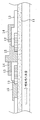
- FIG. 3 is a photograph showing a flat tubular support in a flat tubular segmented solid oxide fuel cell according to an embodiment of the inventive concept.
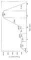
- FIG. 4 is a graph illustrating thermogravimetric analysis of a cathode paste and a binder in a flat tubular segmented solid oxide fuel cell according to an embodiment of the inventive concept.
- FIG. 5 is a graph showing the sintering conditions of the anode paste in the flat-shaped segmented solid oxide fuel cell according to an embodiment of the present invention.
- FIG. 6 is a schematic diagram illustrating a manufacturing process of a unit cell in a flat tubular segmented solid oxide fuel cell according to an embodiment of the inventive concept.
- FIG. 7 is an actual photograph of a three-cell SIS SOFC in a flat segment segmented solid oxide fuel cell according to an embodiment of the inventive concept.
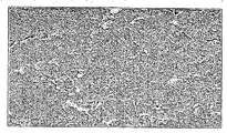
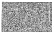
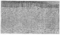
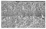
- FIGS. 8A and 8B are photographs showing the anode surface microstructure before and after reduction in a flat tubular segmented solid oxide fuel cell according to an embodiment of the inventive concept.
- FIGS. 9A to 9C are enlarged photographs of a fuel electrode according to a thickness of a 5-cell SIS SOFC in a flat tubular segmented solid oxide fuel cell according to an embodiment of the inventive concept.
- FIGS. 10A to 10C are photographs illustrating the microstructure of a fuel electrode according to the thickness of a 5-cell SIS SOFC in a flat tubular segmented solid oxide fuel cell according to an embodiment of the inventive concept.
- FIG. 11 is a graph comparing current-voltage-output curves according to anode thickness in a flat tubular segmented solid oxide fuel cell according to an embodiment of the inventive concept.
- FIG. 12 is a graph illustrating an AC impedance comparison according to anode thickness in a flat tubular segmented solid oxide fuel cell according to an embodiment of the inventive concept.
- FIG. 13 is a graph comparing maximum output density for each temperature according to anode thickness in a flat tubular segmented solid oxide fuel cell according to an embodiment of the inventive concept.
- FIG. 14 is a graph illustrating sintering conditions of a cathode paste in a flat tubular segmented solid oxide fuel cell according to an embodiment of the inventive concept.
- 15A and 15B are actual photographs of a 5-cell SIS SOFC in a flat-shaped segmented solid oxide fuel cell according to an embodiment of the inventive concept.
- FIG. 16A is a photograph illustrating a fracture surface of a unit cell in a flat tubular segmented solid oxide fuel cell according to an embodiment of the inventive concept.
- FIG. 16B is a photograph showing an interface between an air electrode and an electrolyte in a flat tubular segmented solid oxide fuel cell according to an embodiment of the inventive concept.
- FIG. 16C is a photograph showing an interface between a fuel electrode and a support in a planar segment solid oxide fuel cell according to an embodiment of the inventive concept.
- 16D is a photograph showing an interface between an air electrode and an Ag-glass in a flat-segment solid oxide fuel cell according to an embodiment of the inventive concept.
- 16E is a photograph showing an interface between a fuel electrode and a connector in a flat-segment solid oxide fuel cell according to an embodiment of the inventive concept.
- FIG. 17A and 17B are photographs showing line scaning for identifying components of a cathode functional layer (C.F.L) and a cathode current collecting layer (C.C.L) in a flat-segment segment solid oxide fuel cell according to an embodiment of the inventive concept.
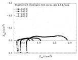
- 18A and 18B are graphs showing a current-voltage-output curve of a 5-cell SIS SOFC using a composite cathode in a flat-shaped segmented solid oxide fuel cell according to an embodiment of the inventive concept.
- 19A and 19B illustrate A.C. of a five-cell SIS SOFC using a composite cathode in a flat tubular segmented solid oxide fuel cell according to an embodiment of the inventive concept. This graph shows the impedance.
- FIG. 20 is a cross-sectional view of the unit cell of the cathode current collector layer LSCF 57 and the composite cathode current collector layer LSCF / LSCo 20 in the planar segmented solid oxide fuel cell according to an embodiment of the inventive concept. This is a graph comparing the impedance.
- top, bottom, top, bottom, or top, bottom, etc. are used to distinguish relative positions in the component.
- the upper part may be called the lower part and the lower part may be named the upper part without departing from the scope of the present invention. .
- FIG. 1 is a schematic perspective view of a flat tubular segmented solid oxide fuel cell according to an embodiment of the inventive concept
- FIG. 2 is a unit cell of a flat tubular segmented solid oxide fuel cell cut along line AA ′ of FIG. 1.
- Figure 3 is a schematic cross-sectional view
- Figure 3 is a photograph showing a flat tubular support in a flat tubular segmented solid oxide fuel cell according to an embodiment of the present invention.
- the planar segment solid oxide fuel cell may include a unit cell 5.
- the unit cell 5 may include a flat tubular support 11, a fuel electrode 12, an electrolyte layer 13, an air electrode 14, and a connecting member 15.
- the flat tubular support 11 is a flow path 8 of the fuel gas, and serves as a support for coating the anode 12.
- the flat tubular support 11 connects the plurality of unit cells 5 and thus may be formed of a non-conductive material.
- the flat tubular support 11 may include a flat portion 11a, a curvature portion 11b, and a plurality of fuel passages 8.
- the unit cell 5 including the fuel electrode 12, the electrolyte layer 13, the air electrode 14, and the connecting member 15, which will be described below, may be disposed on the flat portion 11a.
- the curvature portion 11b may be formed at both ends of the flat portion 11a and may have a curvature having a predetermined radius.
- the fuel passage 8 may have a hollow portion formed inside the flat tubular support 11, and fuel may flow through the fuel passage 8.
- the fuel passage 8 may have a circular cross section, but is not necessarily limited thereto. Referring to FIG. 3, the fuel passage 8 may be formed in an elliptical shape having a different radius of curvature, and may be easily changed by those skilled in the art.
- the anode 12 may be located on the flat tubular support 11.
- the anode 12 may be formed using a slurry prepared by mixing nickel oxide (NiO) powder, yttria stabilized zirconia (YSZ) powder, a binder, a homogeneous agent, a dispersant, a plasticizer and a solvent.
- NiO nickel oxide
- YSZ yttria stabilized zirconia
- the electrolyte layer 13 may be located on the fuel electrode 12.
- the electrolyte layer 13 may be formed by coating a slurry prepared by mixing zirconia (ZrO 2 ) -based powder, a binder, a homogeneous agent, a dispersant, a plasticizer, and a solvent on the fuel electrode 12.
- ZrO 2 zirconia
- the cathode layer 14 is formed in a multilayer structure including an LSCF (L 0.6 S 0.4 C 0.2 F 0.8 ) -GDC layer and an LSCF (L 0.6 S 0.4 C 0.2 F 0.8 ) -LSCo (La 0.6 Sr 0.4 Co). Can be.
- the connecting member 15 may be formed to electrically connect the anode 12 of the unit cell 5 and the cathode 14 of the other unit cell 5 in the flat segmented solid oxide fuel cell.
- the connecting member 15 may be formed using silver-glass paste, but may be used without limitation as long as it is a material commonly used in the art.
- yttria stabilized zirconia is used as a main raw material to form the flat tubular support 11 of the flat tubular segmented solid oxide fuel cell, and activated carbon powder is used as the pore forming agent. Then, 10 to 15 wt% of the activated carbon powder is mixed with respect to 100 wt% of YSZ.
- the yttria stabilized zirconia (YSZ) is yttria stabilized with more than 2 mol% and not more than 5 mol% of yttria Zirconia can be used.
- Yttria stabilized zirconia (YSZ) to which yttria of 2 mol% or less is added has a high strength, so that the thickness of the flat support 11 may be reduced, but a problem arises in that the ion conductivity is low, and 5 mol% or more.
- Yttria stabilized zirconia (YSZ) to which yttria is added has a high ion conductivity, but in order to maintain the strength of the flat support 11 above a certain level, the thickness of the flat support 11 must be increased. Occurs.
- the yttria stabilized zirconia uses yttria stabilized zirconia to which yttria of 2 mol% or more and 5 mol% or less is added, preferably yttria stabilized zirconia to which 3 mol% of yttria is added ( 3YSZ) can be used. If the activated carbon powder is less than 10wt%, there is a problem that the porosity of the flat tubular support is lowered, and if it exceeds 15wt%, the porosity is increased but the compressive strength is lowered.
- the mixture of the mixed YSZ and activated carbon powder is made into a slurry and homogenized by wet ball milling.
- the mixture of the homogenized YSZ and activated carbon powder may be dried in a hot box.
- a paste may be formed by kneading by adding a binder, a plasticizer, a lubricant, and a solvent to the mixture of the powdered YSZ and the activated carbon powder.
- the binder may be a water-based binder YB-13D.
- the binder may serve to bind the powdered mixture and simultaneously form pores with the activated carbon. Distilled water may be used as the solvent.
- the paste may then be extruded into the flat tubular support 11 using an extruder.
- the extrusion process may be extrusion molded so that the moisture of the paste is evenly distributed before extrusion.
- the extruded flat tubular support 11 may be dried.
- the extruded flat tubular support 11 may cause warpage or cracking due to evaporation of the solvent during drying, and may use a thermo-hygrostat to prevent warpage or cracking due to variation in moisture evaporation as a solvent.
- the dried flat tubular support 11 can be plasticized.
- the additive formed in the flat tubular support 11 may be removed, and the strength may be given to the coating process of the anode 12.
- the pre-sintering process conditions are related to the combustion of activated carbon and binders, which are the main additives. If the elevated temperature condition is increased, internal cracks or combustion gases are ignited due to the gas caused by the combustion of activated carbon and binders, and local thermal shock is caused. This may cause breakage of the flat tubular support 11. Accordingly, the activated carbon and the binder may be slowly burned to disperse gas generation, and the grain growth time of the flat tubular support 11 may be given to have the mechanical strength required in the manufacturing process. Subsequently, the sintered flat tubular support 11 can be sintered to complete the flat tubular support 11.
- the anode 12 may be formed on the flat tubular support 11.
- the anode 12 may generally use Cermet, which is a metal and electrolyte mixture.
- the metal and electrolyte mixture Cermet may be a nickel-Yittria stablized zirconia cermet, a nickel-scandia stablized zirconia cermet, or a nickel-gadonia stabilized ceria cermet.
- Gadolinia doped ceria cermet) mixed cermet may be used.
- the anode 12 serves to generate hydrogen ions used for electrochemical reaction by oxidizing fuel gas, and forms a triple phase boudnary (TPB) where oxygen ions and hydrogen ions meet to form electrons in an electrochemical reaction. It can serve to emit.
- TPB triple phase boudnary
- oxygen ions and hydrogen ions meet to form electrons in an electrochemical reaction. It can serve to emit.
- it may be used as a current collector layer connecting the unit cells 5 connected in series, and may be a passage through which the reaction product
- the output is improved by increasing the three-phase interface.
- the output may be reduced due to concentration overvoltage due to the inadequate release of the reaction product.
- the anode 12 may be formed of an anode paste for screen printing.
- thin films produced by screen printing are determined by factors such as printer settings, substrates, pastes and screen masks.
- the microstructure of the thin film is determined by the properties of the paste, which is determined by the particle size of the powder, solid lodaing and additives (eg, organic binders, dispersants, solvents). May be affected.
- additives eg, organic binders, dispersants, solvents.
- an organic binder maintains the shape of the paste after screen printing and maintains the connection of the particles during sintering.
- the dispersant may help to uniformly mix the powder and uniformly disperse the gaps between the particles to serve to sinter well.
- the solvent serves to determine the viscosity of the paste and may also be used to dissolve the binder.
- the SOFC electrolyte paste for screen printing it can be produced with a low binder content (binder content 0.231.0 wt.% Of solid). Increasing the content of the binder increases the bonding strength of the powder during sintering, thereby contributing to the formation of a dense film, but defects such as pinholes and cracks may occur due to the gas generated by the combustion of the binder.
- the binder may be used as a shape maintaining agent, a role of bonding of powder, and a pore forming agent. Since the anode requires the formation of a three-phase interface and a porous microstructure from which the product is discharged, it is necessary to increase the binder content to form pores.
- the electrolyte layer 13 may be formed on the fuel electrode 12.
- the electrolyte layer 13 must have airtightness as it functions as an electron mediator between the fuel electrode 12 and the air electrode 14 and prevents leakage of fuel gas and oxygen-containing gas.
- the electrolyte layer 13 may be formed of a zirconia (ZrO 2 ) -based material.
- the electrolyte layer 13 may be formed of zirconia doped with rare earth elements of 3 to 15 moles.
- the rare earth element may be Sc, Y, La, Ce, Pr, Nd, Pm, Sm, Eu, Gd, Tb, Dy, Ho, Er, Tm, Yb, Lu, and the like.
- the material of the support may be made of GDC, SDC, ScZ and LSGM.
- the electrolyte layer 13 may be formed after masking a portion on which the connecting member 15 is to be coated with a masking tape.
- the cathode 14 may be formed on the electrolyte layer 13.
- Performance of the flat-segment solid oxide fuel cell may have the largest influence on the voltage drop (iR-drop) caused by a cathode current collector layer (CCC).
- CCC cathode current collector layer
- Increasing the thickness of the cathode 14 increases the output density of the SIS-SOFC due to the reduction of the sheet resistance, and may use the highly conductive cathode current collector layer material to obtain higher output density characteristics.
- the flat tube solid oxide fuel cell may manufacture a cathode current collector layer using LSCo (La 0.6 Sr 0.4 Co Oxide) ( ⁇ 1000 S / cm) having high electron conductivity.
- the LSCo can be applied in a functionally graded composite cathode layer method to solve the problem caused by the higher thermal expansion coefficient (Thermal Expansion Coefficient, TEC 17 ⁇ 24x10 -6 ) than the electrolyte.
- the functionally graded composite cathode layer method may be a method for preventing physical separation or cracking at an interface when a material having a different thermal expansion coefficient (TEC) rate is used.
- TEC thermal expansion coefficient
- the cathode 14 of the SIS-SOFC may be fabricated in two layers to play a role.
- the oxygen molecules may be adsorbed by the cathode 14, receive electrons, oxidize to oxygen ions, and then send them to the electrolyte by thermodynamic driving force.
- the cathode current collector layer CCL
- each unit cell 5 constituting the SIS-SOFC is connected in series to supply electrons to assist in oxidation of oxygen.
- it may have a great effect on the increase / decrease of performance due to ohm resistance.
- the cathode functional layer CFL and the cathode current collecting layer CCL are similar to the anode 12 manufactured above, and the cathode 14 should be made of a porous microstructure without cracking.
- a paste having an appropriate viscosity may be manufactured by adjusting the content of the organic binder and the solid loading amount.
- uniform dispersion is important because it is manufactured using two similar powders of LSCF and LSCo.
- 2.5 mg / m 2 of fish oil may be added in proportion to the specific surface area (BET) of the powder.
- the connecting member 15 may be formed outside the cathode 14.
- the connecting member 15 may be formed for electrical communication of the segmented solid oxide fuel cell.
- the connecting member 15 electrically connects the anode 12 of the unit cell 5 and the cathode 14 of the other unit cell 5 in the segmented solid oxide fuel cell to enable electrical communication between the unit cells.
- the connecting member 15 may be formed by coating a silver-glass paste.
- the connecting member 15 should have excellent electrical conductivity and ensure gas sealing properties, and may exhibit excellent electrical conductivity by silver powder included in the silver-glass paste, and may exhibit gas sealing effect by glass powder. have.
- NiO and 10mol% Sc 2 O 3 - 1mol % CeO 2 - to 89mol% ZrO 2 (10Sc1CeSZ) 50 The mixture of the powder with 50wt% (volume ratio: 40vol% Ni, 60vol% 10Sc1CeSZ ).
- step 1) After mixing the mixed powder slurry and binder prepared in step 1) and step 2), use a high speed centrifugal mixer to increase the mixer speed in the following order to make a paste. (500 rpm 5 minutes 1000 rpm 5 minutes 2000 rpm 5 minutes)
- the anode paste prepared in Step 3) is milled by repeating three roll mills twice.
- a pre-made screen mask (Mesh count: SUS 200, Emulsion thickness: 20um) was used, and a fuel electrode having a desired thickness was manufactured by adjusting the number of printings.
- thermogravimetric analysis TGA of an organic binder (Ethyl Cellulose 50) and an anode paste was performed, and thermogravimetric analysis of the anode paste and the binder is shown in FIG. 4.
- the organic binder started pyrolysis from 200 and the combustion was completed at 450, and the produced anode paste can be confirmed that combustion of the additive is performed from 100 to 300 initially.
- FIG. 5 shows the sintering condition of the anode paste in consideration of the binder combustion.
- SIS-SOFC was manufactured as shown in FIG. 6 to manufacture SIS-SOFC.
- NiO and ScSZ were quantified 5: 5 and mixed with a solvent (-Terpineol) and a binder (Ethyl cellulose) by using a high-speed centrifugal mixer to prepare a cathode paste.
- the anode paste prepared using the screen mask was coated on the 3YSZ sintered support, and the thickness of the anode was adjusted by increasing the number of screen printing, and heat-treated at 1000 to 3 hours.
- the ScSZ was coated using a vacuum slurry coating method and heat-treated again at 1000 for 3 hours, and coated with GDC (Ce 0.9 Gd 0.1 O) in the same manner. After sintering at 1400 for 5 hours.
- LSCF La 0.6 Sr 0.4 Co 0.2 Fe 0.8 ,
- GDC GDC
- FIG. 9A to 9C enlarged photographs of the anode part of the unit cell in which the anode (Ni / ScSZ) thicknesses are 14 (FIG. 9A), 20 (FIG. 9B), and 40 (FIG. 9C) are shown.
- FIG. 8A and FIG. 8B in which only the anode was screen printed to observe the microstructure, it was confirmed that nickel, Scandia stabilized zirconia, and a pore network structure were formed well. This indicates that the three-phase interface is well achieved, and that the pores can smoothly supply fuel gas and discharge product.
- FIG. 10A to 10C the overall microstructure of the unit cell of the 3-cell SIS-SOFC fabricated from the anode (Ni / ScSZ) 14 (FIG. 10A), 20 (FIG. 10B), and 40 (FIG. 10C) is illustrated. . Except for the anode, the electrolyte ScSZ ⁇ 9, the interlayer GDC ⁇ 3, and the cathode composite electrodes (LSCF / GDC, LSCF, LSCF / LSCo, LSCo) ⁇ 27 can be confirmed to be the same.
- the anode (Ni / ScSZ) 14 has a maximum power density of 315 mW / cm 2
- the anode (Ni / ScSZ) 20 has a maximum power density of 520 mW / cm 2
- the anode (Ni / ScSZ) 40 has a maximum power density of 450 mW / cm 2 is shown.
- the increase in the maximum power density of about 66% was confirmed when the anode was increased from 14 to 20.
- the maximum power density decrease of about 14% was confirmed when the anode 20 was increased from 40 to 40, which is caused by the concentration overvoltage caused by the insufficiency of the supply of fuel gas and the discharge of the product as the anode thickness increased.
- a current-voltage-output comparison according to anode thickness is shown at 750.
- the anode 14 measured the ohm resistance 0.4641 cm 2 , the polarization resistance 0.6440 cm 2 , the anode 20 measured the ohm resistance 0.2737 cm 2 , the polarization resistance 0.5626 cm 2 , the anode 40 measured the ohm resistance 0.3274 cm 2 , and the polarization resistance 0.6074 cm 2 .
- the ohmic resistance decreased by about 41% and the polarization resistance decreased by about 13%. In comparison with 20 and 40, ohmic resistance increased about 20% and polarization resistance increased about 8%.
- the maximum power density was shown at 20 and slightly decreased at 40, and it was found to be in agreement with the I-V curve. This may be due to concentration overvoltage due to thickness and interference with the release of fuel reaction products at TPB. Referring to FIG. 12, an AC impedance comparison according to anode thickness is shown at 750.
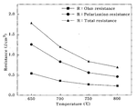
- FIG. 13 a comparison of the maximum power density for each temperature according to the thickness of the anode (Ni / ScSZ) is shown. It can be seen that as the temperature increases from 600 to 800, a difference in the maximum power density of the anode thickness 14 and 20 occurs. As the temperature increases, the cell having a thickness of 20 in the anode has a lower activation overvoltage at the three-phase interface than the cell having a thickness of 14 in the anode, and the output increases with the effect of increasing the ion conductivity of the electrolyte and decreasing the cathode activation overvoltage. In addition, in the case of the anode 40, the ohmic resistance of 14 decreased by 30%, but the polarization resistance decreased by 6%. This result indicates that as the thickness of the anode increases, the increase of the three-phase interface contributes to a positive effect, but when it exceeds the optimum point, the output decreases due to factors such as fuel gas supply and product discharge.
- organic binder (Ethyle Celllulose-cp50) was mixed with 4.06wt.% Of total weight and solvent (-terpineol) with 12.19wt.% Of total weight. Mix for 5 minutes.
- step 1) After mixing the mixed powder slurry and binder prepared in step 1) and step 2), use a high-speed centrifugal mixer to increase the mixer speed in the following order to prepare a paste. (500rpm 5min 1000rpm 5min 2000rpm 5 minute)
- the cathode functional layer paste prepared in Step 3) is milled by repeating three roll mills twice.
- a cathode functional layer having a desired thickness was manufactured by adjusting the number of printing using a pre-made screen mask (Mesh count: SUS 200, Emulsion thickness: 20).
- the organic binder (Ethyle Celllulose-cp50) and the solvent (-terpineol) were mixed by the total weight using the ratio of Table 3, and then 5 minutes at 2000 rpm using a high speed centrifugal mixer. Mixed during.
- step 1) After mixing the mixed powder slurry and binder prepared in step 1) and step 2), use a high-speed centrifugal mixer to increase the mixer speed in the following order to prepare a paste. (500rpm 5min 1000rpm 5min 2000rpm 5 minute)
- the cathode collector layer paste prepared in Step 3) is milled by repeating three roll mills twice.
- the sintering conditions were stepped up at 200 ⁇ 300 step by step considering the combustion of the dispersant (fish oil) and organic binder (Ethyl Cellulose 50). After heating up to 3.33 / min up to 200 was maintained for 3 hours, after heating up to 0.56 / min up to 250 and maintained for 2 hours, after heating up to 0.42 / min up to 300 and maintained for 1 hour, the additives were gradually burned and cracked. Was prevented.
- the arrival of oxygen to the three-phase interface of the cathode functional layer is important.
- to prevent particle growth and increase the temperature increase rate to 3.81 / min to 1100, which is a sintering temperature in order to produce a porous microstructure particle growth was prevented, and it was maintained for 2 hours to prevent sintering into a dense film.
- 14 shows the sintering conditions of the cathode paste in consideration of the binder combustion.
- NiO and ScSZ were 5: 5 quantified to prepare SIS-SOFC, and then mixed with a solvent (-Terpineol) and a binder (Ethyl cellulose) by using a high-speed centrifugal mixer to prepare an anode paste.
- the anode paste prepared using the screen mask was coated on the 3YSZ sintered support, and the thickness of the anode was adjusted by increasing the number of screen printings, and heat-treated at 1000 for 3 hours.
- the ScSZ was coated using a vacuum slurry coating method and heat-treated again at 1000 for 3 hours, and coated with GDC (Ce 0.9 Gd 0.1 O) in the same manner. After sintering at 1400 for 5 hours.
- LSCF La 0.6 Sr 0.4 Co 0.2 Fe 0.8 ,
- GDC GDC
- the fracture surface microstructure of the 5 cell SIS-SOFC is shown. It can be seen that the anode (Ni / ScSZ) ⁇ 20, the electrolyte (ScSZ) ⁇ 9, the interlayer (GDC) ⁇ 3, the cathode composite electrode (LSCF / GDC, LSCF, LSCF / LSCo, LSCo) ⁇ 27.
- the interface between the cathode functional layer (CFL LSCF / GDC) and the electrolyte is porous, and it can be confirmed that the electrolyte and the cathode functional layer are well connected, and the sintering is performed without the presence of cracks and large growth particles to the ends of the cathode. It was confirmed.
- the connection was well performed without peeling or cracking, and the barrier layer formed in the middle of the anode and the support may be formed during the vacuum coating of the ScSZ thin film (about 2 to 3).
- Cell performance measurements show a porous membrane that does not affect fuel gas permeation and product emissions.
- the sealing and connection state of the coated connecting material (Ag-glass) was confirmed.
- the cathode-connecting material was well attached to the cathode without peeling off, and the connecting material was coated without pores on the anode to prevent leakage of fuel gas, and each unit cell was connected.
- FIG. 17A and 17B show line scans for each element for identifying the components of the cathode functional layer (C.F.L) and the cathode current collector layer (C.C.L).
- the cathode functional layer (LSCF / GDC) was manufactured to about 7-8, and the composite cathode current collector layer (LSCF / LSCo) was manufactured to 19-20.
- the Cobalt (Co) content was increased and the Iron (Fe) content was decreased.
- paste-1 (LSCF 100%), paste-2 (LSCF 70%, LSCo 30%), paste-3 (LSCF 50%, LSCo 50%), paste-4 (LSCF 30%, LSCo 70%), paste It can be seen that the composite electrode of LSCF and LSCo is well formed up to -5 (LSCo 100%).
- the fuel cell was operated at the temperature range of 650 ⁇ 800 under the condition of 300 sccm of hydrogen flow and 1.5L / min of air.
- the maximum output density of 238mW / cm 2 (0.95W) at 700 the maximum output density of 370mW / cm 2 (1.48W), a maximum output density in 750 523mW / cm 2 (2.09W) , the maximum power density of 800 at 650 618 mW / cm 2 (2.47 W) performance.
- the output density is shown in FIG. 18A, and the output is shown in FIG. 18B.
- ohmic resistance was reduced by about 47% and polarization resistance was increased by about 5% compared to the cathode collector LSCF 57 at 750.
- the maximum power density increased by about 1.8 times.
- the application of a highly conductive composite cathode current collector to the SIS-SOFC can reduce the iR-drop in the direction of current propagation, which acts as a resistance loss factor.
- high-conductivity cathode materials can be used to reduce cathode polarization resistance and ohmic resistance, resulting in high power density.
Abstract
A method for manufacturing a flat-tube type segment solid oxide fuel cell, according to one embodiment of the technical concept of the present invention, can comprise: mixing NiO and Sc2O3-CeO2-ZrO2 powder; adding ethanol to the mixed powder, adding a zirconia ball thereto, and then proceeding with wet ball milling; proceeding with the wet ball milling, drying the mixed powder in a dryer, and then forming fine mixed powder; quantifying the mixed powder, adding a solvent (-terpineol) and a dispersing agent, and then mixing the mixed powder by using a high-speed centrifugal mixer (planetary centrifugal mixer, ARM-310); mixing a binder (organic binder) (ethyle cellulose-cp50) and the solvent (-terpineol), and then mixing the mixture by using the high-speed centrifugal mixer; mixing the mixed powder slurry and the binder and then producing paste by using the high-speed centrifugal mixer; repeatedly milling the paste with a three-roll mill; and forming an anode from the milled paste by using a screen mask.
Description
본 발명은 고체산화물 연료전지에 관한 것으로, 보다 상세하게는, 평관형 세그먼트 고체산화물 연료전지의 제조에 있어서 연료극 두께의 최적점을 찾고, 상기 연료극과 조합하여 높은 출력밀도를 얻을 수 있는 공기극을 포함하는 평관형 세그먼트 고체산화물 연료전지 및 그 제조방법에 관한 것이다.BACKGROUND OF THE INVENTION 1. Field of the Invention The present invention relates to a solid oxide fuel cell. More particularly, the present invention relates to a solid oxide fuel cell, and more particularly, includes an air electrode capable of finding an optimum point of the anode thickness in combination with the anode and obtaining a high output density. It relates to a flat tubular segment solid oxide fuel cell and a method of manufacturing the same.
연료전지는 연료로부터 화학적 반응을 통해 직접 전기를 발생시키는 장치로서, 내부 구성에 따라 다양한 종류가 있다. 연료전지는 음극(연료극, anode), 전해질(electrolyte), 양극(공기극, cathode)을 통해 발생된 전기를 집전체(electrical collector)를 통해 외부의 전력으로 발생시키는 과정으로 작동된다.A fuel cell is a device that generates electricity directly through a chemical reaction from a fuel, and there are various kinds according to its internal configuration. The fuel cell operates by generating electricity generated through an anode, a cathode, an electrolyte, an anode, and an external power through an electrical collector.
연료전지의 종류는 대표적으로 고분자 전해질 연료전지(PEMFC, Polymer Electrolyte Membrane Fuel Cell), 인산형 연료전지(PAFC, Phosphoric Acid Fuel Cell), 탄산염 연료전지(MCFC, Molten Carbonate Fuel Cell), 고체산화물 연료전지(SOFC, Solid Oxide Fuel Cell) 등이 있다. 연료로는 H2, CO, CH4, LNG, LPG, CH3OH, Diesel, Biogas, Coal gas 등이 다양하게 사용되고, 탄화수소 계열 연료에 대한 단위 셀(cell)당 기전력(OCV, Open Circuit Voltage)은 1.00~1.07V 정도 된다.The types of fuel cells are typically polymer electrolyte fuel cells (PEMFC), phosphate acid fuel cells (PAFC), carbonate fuel cells (MCFC), and solid oxide fuel cells. (SOFC, Solid Oxide Fuel Cell). As fuel, H 2 , CO, CH 4 , LNG, LPG, CH 3 OH, Diesel, Biogas, Coal gas, etc. are used in various ways, and the electromotive force per unit cell (OCV, Open Circuit Voltage) for hydrocarbon fuels Is about 1.00 ~ 1.07V.
고체 산화물 연료전지(SOFC)는 고온에서 작동하므로 에너지전환 효율이 가장 높은 것으로 알려져 있고, 구조 및 형태에 따라 다양한 모델이 개발되고 있으며, 제조과정 또한 다양하다. 사용되는 기본 재료로는 음극층에 NiO/YSZ cermet, 전해질 층에 YSZ(Yttria-stabilized Zirconia) 또는 GDC(Gadolium-stabilized Ceria), 양극층에 (La,Sr)MnO3, (La,Sr)(Co, Fe)O3 등을 기본으로 한 소재계열이 많이 사용되고 있다. Solid oxide fuel cells (SOFCs) are known to have the highest energy conversion efficiency because they operate at high temperatures, and various models are being developed according to structures and shapes. The basic materials used are NiO / YSZ cermet in the cathode layer, Yttria-stabilized Zirconia (YSZ) or Gadolium-stabilized Ceria (GDC) in the electrolyte layer, and (La, Sr) MnO 3 , (La, Sr) ( Many material series based on Co, Fe) O 3 and the like are used.
평판형 고체산화물 연료전지는 음극, 전해질, 양극을 얇은 플레이트(plate)로 성형한 후 이를 분리판과 교대로 적층하고, 밀봉재(sealant)로 밀봉하여 연료, 예를 들어, H2 가스를 음극면에, 공기를 양극면에 공급하고, 온도를 약 6501,000정도로 유지하면서 전기를 발생시킨다. 보통 평판형에서 발생되는 전력밀도는 400700/(peak power 기준, 대략 0.50.7V범위)로 높은 것으로 알려져 있으나, 고온 작동에 따른 셀의 물리적 변형, 글라스 실링(glass sealing) 문제, 공기극 측에서 전기 연결재(electrical collector)의 산화부식에 따른 전기저항 증가와 전력 손실 발생 등의 문제로, 셀/스텍(cell/stack)의 장기 고온 안정성과 대형화에 장애가 되고 있다.In the flat solid oxide fuel cell, a cathode, an electrolyte, and an anode are formed into thin plates, alternately stacked with a separator plate, and sealed with a sealant to seal fuel, eg, H 2 gas, with a cathode surface. Air is supplied to the anode surface to generate electricity while maintaining the temperature at about 6501,000. Usually, the power density generated in the flat plate type is known to be high as 400700 / (peak power standard, about 0.50.7V range), but the physical deformation of the cell due to the high temperature operation, the glass sealing problem, the electrical connection material on the cathode side Due to problems such as increase of electrical resistance and power loss due to oxidation corrosion of electrical collectors, there are obstacles to long-term high temperature stability and enlargement of cells / stacks.
원통형(tubular type) 고체산화물 연료전지는 연료전지 셀 형태를 원형(tube 형)으로 제작하여, 음극, 전해질, 양극을 구성하고, 튜브의 길이방향을 따라 전기 연결재(electrical collector)를 가공, 부착하며, 이를 통해 인접한 셀과 전기적으로 연결되는 형태이다. 상기 원통형 고체산화물 연료전지는 몇 개의 튜브가 번들(bundle)로 묶여진 스텍으로 이루어진다. 미국특허 US 2007/0148523 A1에서는 각 원통형 셀을 와이어 등을 사용하여 전기적으로 연결하는 방법이 예시되어 있다.The tubular solid oxide fuel cell is manufactured in the form of a fuel cell cell in the form of a tube, forming a cathode, an electrolyte, and an anode, and processing and attaching an electrical collector along the length of the tube. In this way, the cells are electrically connected to adjacent cells. The cylindrical solid oxide fuel cell consists of a stack in which several tubes are bundled. US 2007/0148523 A1 illustrates a method of electrically connecting each cylindrical cell with a wire or the like.
원통형 연료전지에서, 공기공급은 튜브 내측으로 이루어지며(이 경우 양극 지지층(cathode-supported) type으로 제작), 연료는 튜브 외측에서 공급된다. 따라서, 튜브 외측에는 환원성 분위기로 인해 일반 금속재를 전기 연결재(electrical collector)로 사용할 수 있다. 음극 지지체(anode-supported) 형태로서 연료와 공기가 반대로 공급될 수 있으나, 이 경우 전기 연결재에 대한 문제가 대두된다. 보통 양극 지지층 형태의 원통형은 기계적 특성과 장기 고온 안정성은 매우 우수하나, 셀 자체 내에서의 전기저항 과다와 출력손실 증가가 커서, 대부분 실제 전기출력이 통상 200/ 이하의 낮은 값을 보이고, 제조 비용이 높은 것으로 알려져 있다.In a cylindrical fuel cell, the air supply is made inside the tube (in this case made of a cathode-supported type) and the fuel is supplied outside the tube. Therefore, due to the reducing atmosphere, the general metal may be used as an electrical collector outside the tube. Fuel and air can be supplied in reverse as an anode-supported form, but this poses a problem for electrical connectors. Cylindrical in the form of an anode support layer is usually excellent in mechanical properties and long-term high temperature stability, but due to the excessive electrical resistance and increase in output loss in the cell itself, most of the actual electrical output is usually lower than 200 /, and manufacturing cost This is known to be high.
SOFC는 전해질과 전극이 고체 상태이기 때문에 여러 가지 형태의 셀(cell)로 제조가 가능하고, 연료전지의 지지체(support)에 따라서 연료극 지지체식과 공기극 지지체식 및 전해질 지지체식으로 분류된다.SOFCs can be manufactured in various types of cells because the electrolyte and the electrode are in a solid state, and are classified into a cathode support type, an cathode support type, and an electrolyte support type according to the fuel cell support.
평판형 SOFC는 전력 밀도와 생산성이 높고 전해질 박막화가 가능한 반면, 별도의 밀봉재를 이용한 기체 밀봉이 요구되는 단점이 있고, 고온에서 금속연결재를 사용하기 때문에 크롬 휘발로 인해 전극 효율이 저하되는 문제가 있으며, 열 사이클에 대한 저항성이 낮아 신뢰성이 부족하다는 단점이 있다. 더욱이, 평판형 SOFC는 대면적 셀의 제조가 어려울 뿐만 아니라 대용량 스택(stack)의 제작도 쉽지 않기 때문에, 이러한 문제를 해결하는 것이 실용화의 관건이 된다.Flat SOFCs have high power density, high productivity, and thin electrolyte, but require gas sealing using a separate sealant, and due to the use of a metal connecting material at high temperatures, electrode efficiency is reduced due to chromium volatilization. However, it has a disadvantage of lacking reliability due to low resistance to thermal cycles. Moreover, since flat panel SOFCs are not only difficult to manufacture large-area cells but also easy to manufacture large-capacity stacks, solving these problems becomes a key to practical use.
원통형 SOFC의 경우는 기체 밀봉이 불필요하고 기계적 강도가 우수할 뿐만 아니라 여러 가지 시험 항목에서 신뢰성이 검증되었기 때문에, 상용화에 가장 근접한 SOFC 디자인으로 평가받고 있다. 그러나, 원통형 SOFC는 전류의 이동 경로가 길기 때문에 내부저항이 높고 출력밀도가 낮은 단점이 있다. 또한, 셀의 집합체인 모듈에서 출력되는 전압이 낮기 때문에 운전 중 전력변환 손실이 크며, 그 결과 효율이 떨어진다는 취약점이 있다. 현재, 20kW급 이상의 발전용 SOFC 시스템은 대부분 원통형 또는 개량 원통형 셀을 사용한 스택을 채택하고 있으며, 20kW급 이하의 경우에는 평판형 셀도 채택하고 있다.Cylindrical SOFCs are evaluated as SOFC designs closest to commercialization because they do not require gas sealing, have excellent mechanical strength, and have been tested for reliability in various test items. However, the cylindrical SOFC has a disadvantage of high internal resistance and low power density because of a long current path. In addition, since the voltage output from the module, which is a collection of cells, is low, the power conversion loss during operation is large, and as a result, there is a weakness in efficiency. Currently, SOFC systems for power generation above 20 kW are mostly adopting stacks using cylindrical or improved cylindrical cells, and in the case of 20 kW or lower, flat cells are also adopted.
기존의 원통형 SOFC는 구조적으로 가스 밀봉이 용이하지만 전류 흐름이 길어져 전력 밀도가 낮아지는 단점이 있다. 평판형 SOFC는 높은 전력 밀도를 갖지만 구조적으로 스택 구성을 위한 밀봉의 어려움이 있다. 이에 반하여, 평관형 세그먼트 SOFC는 기본적인 구조는 원통형 SOFC를 따르지만 평판형 SOFC의 장점을 부가하여 설계되었기 때문에 가스 밀봉이 용이하고, 담금 코팅, 스프레이 코팅, 스크린 프린팅 등 다양한 코팅법이 적용될 수 있다. 또한, 양면에 전극 구성이 가능하기 때문에 한 모듈 안에서 전류 흐름으로 인한 저항을 최소화할 수 있으며, 고집적화를 이루어 스택의 부피가 줄어드는 장점이 있다. 평판형 SOFC의 경우에는 셀의 휨이나 크랙으로 인해 연료전지의 대형화가 어렵지만, 평관형 세그먼트 SOFC의 경우 지지체의 크기에 제한이 없기 때문에 셀의 대면적화가 가능하다.Conventional cylindrical SOFCs are structurally easy to gas seal, but have a disadvantage of low power density due to longer current flow. Planar SOFCs have high power densities but are structurally difficult to seal for stack construction. On the contrary, since the basic structure follows the cylindrical SOFC, but the basic structure is designed with the advantages of the flat SOFC, gas sealing is easy and various coating methods such as dip coating, spray coating, and screen printing can be applied. In addition, since the electrode can be configured on both sides, the resistance due to the current flow in one module can be minimized, and the stack volume is reduced due to high integration. In the case of a flat SOFC, it is difficult to increase the size of the fuel cell due to the warpage or crack of the cell. However, in the case of the flat-segment SOFC, the size of the support is not limited.
세그먼트 고체산화물 연료전지(SEGMENT-IN-SERIES SOFC; SIS-SOFC)의 연료극은 연료가스를 산화시켜 전기화학반응에 사용되는 수소이온을 생성하는 역할을 하며, 산소이온과 수소이온이 만나는 삼상계면(Triple Phase Boundary, TPB)을 형성하여 전기화학반응으로 전자를 방출하는 역할을 한다. 직렬로 연결된 단위 셀을 연결하는 집전층으로 사용되며, 반응생성물 H2O 가스가 방출되는 통로가 된다.The anode of a segment solid oxide fuel cell (SISG-SOFC) plays a role in oxidizing fuel gas to generate hydrogen ions used for electrochemical reactions, and the three-phase interface where oxygen ions and hydrogen ions meet. It forms Triple Phase Boundary (TPB) and releases electrons by electrochemical reaction. It is used as a current collector layer connecting unit cells connected in series, and becomes a passage through which the reaction product H 2 O gas is discharged.
그리고, 세그먼트 고체산화물 연료전지의 성능은 공기극 집전체(Cathode Current Collect layer, CCC)에 의한 전압강하(iR-drop)가 가장 큰 영향을 미친다. 상기 공기극의 두께를 증가하면 면저항의 감소로 인하여 SIS-SOFC의 출력밀도가 증가되며, 고전도성 공기극 집전층 소재를 사용하면 더 높은 출력밀도 특성을 얻을 수 있다.In addition, the performance of the segmented solid oxide fuel cell is most affected by a voltage drop (iR-drop) caused by a cathode current collector (CCC). Increasing the thickness of the cathode increases the output density of the SIS-SOFC due to the reduction of the sheet resistance, and may use the highly conductive cathode current collector layer to obtain higher output density characteristics.
그러나, 평관형 세그먼트 고체산화물 연료전지는 연료극의 두께가 증가하면 삼상계면의 증가로 출력이 향상되나 임계점을 지나면 반응 생성물의 원활하지 못한 방출로 인하여 농도과전압이 발생하여 출력이 감소된다.However, as the thickness of the anode increases, the output increases as the three-phase interface increases. However, after the critical point, the output increases due to the concentration overvoltage.
본 발명이 해결하고자 하는 과제는, 고체산화물 연료전지의 제조에 있어서 연료극 두께의 최적점을 찾아서 최대의 출력밀도를 얻을 수 있는 평관형 세그먼트 고체산화물 연료전지를 제공하는데 있다.SUMMARY OF THE INVENTION An object of the present invention is to provide a flat-segmented solid oxide fuel cell that can obtain the maximum output density by finding the optimum point of anode thickness in the manufacture of a solid oxide fuel cell.
또한, 본 발명이 해결하고자 하는 다른 과제는, 고전도성 공기극 집전층 소재를 사용하여 더 높은 출력밀도를 얻을 수 있는 평관형 세그먼트 고체산화물 연료전지를 제공하는데 있다.In addition, another problem to be solved by the present invention is to provide a flat-segment solid-state solid oxide fuel cell that can obtain a higher power density by using a highly conductive cathode current collector layer material.
본 발명이 해결하고자 하는 다양한 과제들은 이상에서 언급한 과제들에 제한되지 않으며, 언급되지 않은 또 다른 과제들은 아래의 기재로부터 당업자에게 명확하게 이해될 수 있을 것이다.Various problems to be solved by the present invention are not limited to the above-mentioned problems, and other tasks not mentioned will be clearly understood by those skilled in the art from the following description.
본 발명의 기술적 사상의 일 실시예에 따른 평관형 세그먼트 고체산화물 연료전지의 제조방법은, NiO와 Sc2O3-CeO2-ZrO2 분말을 혼합하고, 상기 혼합된 분말에 에탄올을 첨가한 후, 지르코니아볼을 첨가한 후 습식 볼밀을 진행하며, 상기 습식 볼밀을 진행한 후 건조기에서 건조한 후 미세 혼합분말을 형성하고, 상기 혼합분말을 정량한 후, 솔벤트(-terpineol) 및 분산제를 첨가한 후 고속원심믹서(Planetary Centrifugal Mixer, ARM-310)를 이용하여 혼합하며, 바인더(organic binder)(Ethyle Celllulose-cp50) 및 솔벤트(-terpineol)를 혼합한 후 고속원심믹서를 이용하여 혼합하고, 상기 혼합분말 슬러리와 바인더를 섞은 후, 고속원심믹서를 이용하여 페이스트를 제작하며, 상기 페이스트를 3 롤밀(Three roll mill)로 반복하여 밀링하고, 상기 밀링한 페이스트를 스크린 마스크를 사용하여 연료극을 형성하는 것을 포함할 수 있다.According to an embodiment of the present invention, a method for manufacturing a flat-segment solid oxide fuel cell may include mixing NiO and Sc 2 O 3 -CeO 2 -ZrO 2 powders, and then adding ethanol to the mixed powders. After the addition of the zirconia ball, the wet ball mill proceeds, and after the wet ball mill proceeds to dry in a dryer to form a fine mixed powder, after quantitating the mixed powder, and after adding a solvent (-terpineol) and dispersant Mix using a high speed centrifugal mixer (Planetary Centrifugal Mixer, ARM-310), a binder (organic binder) (Ethyle Celllulose-cp50) and a solvent (-terpineol) after mixing using a high speed centrifugal mixer, the mixing After mixing the powder slurry and the binder, a paste is prepared by using a high-speed centrifugal mixer, the paste is repeatedly milled with a three roll mill, and the milled paste is screened using a screen mask. It may include forming a fuel electrode.
상기 고속원심믹서를 이용하여 페이스트를 제작하는 공정은, 고속원심믹서를 믹서 속도를 증가시켜 페이스트를 제작할 수 있다.In the process of manufacturing the paste using the high speed centrifugal mixer, the high speed centrifugal mixer may be manufactured by increasing the mixer speed.
상기 NiO와 Sc2O3-CeO2-ZrO2 분말은 NiO와 10mol% Sc2O3 - 1mol% CeO2 - 89mol% ZrO2(10Sc1CeSZ)를 50:50wt%로 혼합할 수 있다.The NiO and Sc 2 O 3 -CeO 2 -ZrO 2 powder NiO and 10mol% Sc 2 O 3 - a 89mol% ZrO 2 (10Sc1CeSZ) 50 - 1mol% CeO 2: can be mixed with 50wt%.
상기 혼합분말을 정량한 후, 솔벤트(-terpineol) 및 분산제를 첨가한 후 고속원심믹서(Planetary Centrifugal Mixer, ARM-310)를 이용하여 혼합하는 공정은, 상기 혼합분말을 총 중량 대비 54.7wt%을 정량 한 후, 솔벤트(-terpineol)를 총 중량 대비 24.2wt.% 첨가하고, 분산제로 Fish oil을 총 중량대비 0.5wt.%를 첨가한 후 고속원심믹서(Planetary Centrifugal Mixer, ARM-310)를 이용하여 혼합하는 공정일 수 있다.After quantifying the mixed powder, the solvent (-terpineol) and the addition of a dispersant and then mixing using a high-speed centrifugal mixer (Planetary Centrifugal Mixer, ARM-310), 54.7wt% of the mixed powder by weight After quantification, solvent (-terpineol) is added 24.2wt.% To the total weight, fish oil is added 0.5wt.% To the total weight as a dispersant, and then a high-speed centrifugal mixer (ARM-310) is used. The mixing may be a process.
상기 바인더(organic binder)(Ethyle Celllulose-cp50) 및 솔벤트(-terpineol)를 혼합한 후 고속원심믹서를 이용하여 혼합하는 공정은, 바인더(organic binder)(Ethyle Celllulose-cp50)를 총중량대비 4.1wt.%, 솔벤트(-terpineol)를 총 중량대비 16.4wt.%를 혼합한 후 고속원심믹서를 이용하여 혼합하는 공정일 수 있다.The process of mixing the binder (Ethyle Celllulose-cp50) and the solvent (-terpineol) using a high-speed centrifugal mixer, the binder (organic binder) (Ethyle Celllulose-cp50) to 4.1wt. %, Solvent (-terpineol) may be a process of mixing using a high-speed centrifugal mixer after mixing 16.4wt.% Relative to the total weight.
본 발명의 기술적 사상의 다른 실시예에 따른 평관형 세그먼트 고체산화물 연료전지의 제조방법은, 가소결 평관형 지지체를 형성하고; 상기 평관형 지지체 상에 연료극을 형성하며; 상기 연료극 상에 전해질층을 형성하고; 상기 전해질층 상에 공기극을 형성하며; 상기 공기극 외측에 위치하고, 단위 셀의 연료극과 다른 단위 셀의 공기극을 전기적으로 연결시켜 단위 셀들간의 전기적 소통을 가능하게 하는 연결재를 형성하되, 상기 평관형 지지체 상에 연료극을 형성하는 공정은, NiO와 ScSZ를 5:5 정량한 뒤 용매(-Terpineol), 바인더(Ethyl cellulose)와 함께 고속원심믹서기로 혼합하여 연료극 페이스트를 형성하며, 상기 연료극 페이스트를 상기 가소결 지지체 상에 코팅한 후 열처리하는 공정을 포함하고, 상기 연극극 상에 전해질층을 형성하는 공정은, 상기 단위 셀상의 연결재가 코팅될 부분을 마스킹테이프로 마스킹하고 ScSZ를 코팅한 후 열처리하며, 상기 코팅된 ScSZ 상에 GDC(Ce0.9Gd0.1O)를 코팅한 후 소결하는 공정을 포함할 수 있다.According to another aspect of the present invention, there is provided a method of manufacturing a flat tubular segmented solid oxide fuel cell, including: a sintered flat tubular support; Forming a fuel electrode on the flat tubular support; Forming an electrolyte layer on the anode; Forming a cathode on the electrolyte layer; Located in the outer side of the cathode, and electrically connecting the anode of the unit cell and the cathode of the other unit cell to form a connecting material to enable electrical communication between the unit cells, the step of forming the anode on the flat tubular support, NiO And 5: 5 quantitatively and ScSZ are mixed with a solvent (-Terpineol) and a binder (Ethyl cellulose) with a high-speed centrifugal mixer to form a cathode paste, and the anode paste is coated on the sintered support and then heat treated. The process of forming an electrolyte layer on the play electrode, masking the portion to be coated with the connecting material on the unit cell with a masking tape, and after coating the ScSZ heat treatment, GDC (Ce 0.9 ) on the coated ScSZ Gd 0.1 O) may be coated and then sintered.
상기 가소결 지지체 상에 연료극 페이스트를 코팅하는 공정은 스크린 프린팅법을 이용할 수 있다.The process of coating the anode paste on the sintered support may use a screen printing method.
본 발명의 기술적 사상의 또 다른 실시예에 따른 평관형 세그먼트 고체산화물 연료전지의 제조방법은, 가소결된 평관형 지지체를 형성하고, 상기 가소결 평관형 지지체 상에 NiO와 ScSZ를 5:5 정량한 뒤 용매(-Terpineol), 바인더(Ethyl cellulose)와 함께 고속원심믹서기로 혼합하여 연료극 페이스트를 제작한 후, 상기 연료극 페이스트를 스크린 마스크를 이용하여 코팅하며, 상기 코팅된 연료극 페이스트를 열처리하여 연료극을 형성하고, 상기 열처리 후 연결재가 형성될 부분을 마스킹테이프로 마스킹 한 후 진공 슬러리 코팅법을 이용하여 상기 연료극 상에 ScSZ를 코팅하며, 상기 ScSZ가 코팅된 연료극을 열처리하고, 상기 ScSZ를 코팅한 방법과 동일하게 상기 ScSZ 상에 GDC(Ce0.9Gd0.1O)를 코팅한 후 소결하여 전해질층을 형성하며, LSCF(La0.6Sr0.4Co0.2Fe0.8,)와 GDC를 5:5 정량하여 공기극 복합전극 페이스트를 형성하고, LSCF를 사용하여 공기극 페이스트를 형성하고, 상기 공기극 복합전극 및 공기극 페이스트를 상기 전해질층 상에 스크린 프린트로 코팅하고, 상기 코팅된 공기극 복합전극 및 공기극 페이스트를 열처리하여 공기극을 형성하며, 상기 평관형 지지체 상에 은-유리(Ag-glass) 페이스트를 사용하여 상기 연료극과 공기극을 전기적으로 직렬 연결하는 연결재를 포함할 수 있다.According to another aspect of the present invention, there is provided a method of manufacturing a flat-segmented solid oxide fuel cell, which forms a plasticized flat tubular support and quantifies NiO and ScSZ by 5: 5 on the plasticized flat tubular support. After mixing with a solvent (-Terpineol) and a binder (Ethyl cellulose) by using a high-speed centrifugal mixer to produce an anode paste, the anode paste is coated using a screen mask, and the coated anode paste is heat-treated to produce an anode. After forming, after the heat treatment to mask the portion to be formed with a masking tape and coating the ScSZ on the anode using a vacuum slurry coating method, the ScSZ-coated anode and heat-treated, the method of coating the ScSZ In the same manner as in the coating on the ScSZ GDC (Ce 0.9 Gd 0.1 O) and sintering to form an electrolyte layer, LSCF (La 0.6 Sr 0.4 Co 0.2 Fe 0.8 ,) and GDC 5: 5 to quantify to form a cathode composite electrode paste, to form a cathode paste using LSCF, to coat the cathode composite electrode and cathode paste with a screen print on the electrolyte layer, and to coated the cathode composite electrode and cathode The paste may be heat-treated to form an air electrode, and may include a connecting material that electrically connects the fuel electrode and the air electrode in series using silver-glass paste on the flat tubular support.
상기 연료극의 두께는 14 이상 40 이하로 형성할 수 있다.The fuel electrode may have a thickness of 14 or more and 40 or less.
상기 연료극의 두께는 20로 형성할 수 있다.The fuel electrode may have a thickness of 20.
상기 코팅된 연료극 페이스트를 열처리하여 연료극을 형성하는 공정은 1000에서 3 시간 열처리할 수 있다.The process of forming the anode by heat-treating the coated anode paste may be heat-treated at 1000 to 3 hours.
본 발명의 기술적 사상의 또 다른 실시예에 따른 평관형 세그먼트 고체산화물 연료전지의 제조방법은, LSCF(La0.6Sr0.4Co0.2Fe0.8)와 GDC(Ce0.9Gd0.1O) 분말을 혼합하고, 상기 혼합된 분말에 에탄올을 첨가한 후, 지르코니아볼을 첨가한 후 볼밀을 진행하고, 건조기에서 건조한 후 미세 혼합분말을 형성하며, 상기 혼합분말을 정량한 후, 솔벤트(-terpineol) 및 분산제를 혼합하여 고속원심믹서로 혼합하고, 바인더(organic binder)를 정량한 후, 솔벤트(-terpineol)를 혼합하여 고속원심믹서로 혼합하며, 상기 혼합분말 슬러리와 바인더를 섞은 후, 고속원심믹서를 이용하여 상기 고속원심믹서의 속도를 증가시켜 공기극 기능성층 페이스트를 형성하고, 상기 공기극 기능성층 페이스트를 3 롤밀(Three roll mill)로 밀링을 수행하며, 상기 밀링된 공기극 기능성층 페이스트로 스크린 마스크를 사용하여 공기극 기능성층을 형성하고, 상기 공기극 기능성층 상에 공기극 집전층을 형성하는 공정을 포함할 수 있다.According to another aspect of the present invention, there is provided a method of manufacturing a flat-segmented solid oxide fuel cell, comprising mixing LSCF (La 0.6 Sr 0.4 Co 0.2 Fe 0.8 ) and GDC (Ce 0.9 Gd 0.1 O) powder. After ethanol was added to the mixed powder, zirconia ball was added, the ball mill was carried out, dried in a drier and fine powder was formed. After quantifying the mixed powder, a solvent (-terpineol) and a dispersant were mixed. After mixing with a high speed centrifugal mixer, quantifying a binder (organic binder), and then mixing the solvent (-terpineol) with a high speed centrifugal mixer, after mixing the mixed powder slurry and the binder, using a high speed centrifugal mixer The speed of the centrifugal mixer is increased to form a cathode functional layer paste, milling the cathode functional layer paste with a three roll mill, and the milled cathode functional layer paste. Forming the cathode functional layer using a screen mask, it may comprise a step of forming a conductive layer on the air electrode home cathode functional layer.
상기 공기극 기능성층 및 공기극 집전층을 형성하는 공정은, 상기 분산제 및 유기바인더를 200까지 3.33/min으로 승온한 뒤 3시간 유지하고, 250까지 0.56/min으로 승온한 뒤 2시간 유지하며, 300까지 0.42/min으로 승온한 뒤 1 시간 유지하여 소결할 수 있다.In the process of forming the cathode functional layer and the cathode current collector layer, the dispersant and the organic binder are heated to 3.33 / min to 200 and maintained for 3 hours, and to 250 and maintained for 2 hours, then to 300, to 300. After heating up to 0.42 / min, it can hold | maintain for 1 hour and can be sintered.
상기 건조기에서 건조하는 공정은 90, 24시간 동안 수행할 수 있다.The drying process in the dryer can be carried out for 90, 24 hours.
상기 볼밀은 습식 볼밀일 수 있다.The ball mill may be a wet ball mill.
기타 실시예들의 구체적인 사항들은 상세한 설명 및 도면들에 포함되어 있다.Specific details of other embodiments are included in the detailed description and the drawings.
본 발명의 기술적 사상의 일 실시예에 의한 평관형 세그먼트 고체산화물 연료전지는 삼상계면의 증가로 출력이 향상되고, 농도과전압이 발생하지 않아 출력이 증가될 수 있다.According to an embodiment of the inventive concept, the flat-shaped segmented solid oxide fuel cell may have an improved output due to an increase in three-phase interface, and may have an increased output because no concentration overvoltage occurs.
본 발명의 기술적 사상의 다른 실시예에 의한 평관형 세그먼트 고체산화물 연료전지는 고전도성 공기극 집전층 소재를 사용하여 더 높은 출력밀도 특성을 얻을 수 있다.According to another embodiment of the inventive concept, the flat-segmented solid oxide fuel cell may obtain higher power density characteristics by using a highly conductive cathode current collector layer material.
본 발명의 기술적 사상의 다양한 실시예들은, 구체적으로 언급되지 않은 다양한 효과를 제공할 수 있다는 것이 충분히 이해될 수 있을 것이다. It will be fully understood that various embodiments of the inventive concept may provide various effects not specifically mentioned.
도 1은 본 발명의 기술적 사상의 일 실시예에 따른 평관형 세그먼트 고체산화물 연료전지의 개략적인 사시도이다.1 is a schematic perspective view of a flat tubular segmented solid oxide fuel cell according to an embodiment of the inventive concept.
도 2는 도 1의 A-A' 선을 따라 절단한 평관형 세그먼트 고체산화물 연료전지의 단위 셀에 대한 개략적인 단면도이다.FIG. 2 is a schematic cross-sectional view of a unit cell of a planar segment solid oxide fuel cell cut along the line AA ′ of FIG. 1.
도 3은 본 발명의 기술적 사상의 일 실시예에 따른 평관형 세그먼트 고체산화물 연료전지에서 평관형 지지체를 보여주는 사진이다.3 is a photograph showing a flat tubular support in a flat tubular segmented solid oxide fuel cell according to an embodiment of the inventive concept.
도 4는 본 발명의 기술적 사상의 일 실시예에 따른 평관형 세그먼트 고체산화물 연료전지에서 연료극 페이스트 및 바인더의 열중량 분석을 나타내는 그래프이다.FIG. 4 is a graph illustrating thermogravimetric analysis of a cathode paste and a binder in a flat tubular segmented solid oxide fuel cell according to an embodiment of the inventive concept.
도 5는 본 발명의 기술적 사상의 일 실시예에 따른 평관형 세그먼트 고체산화물 연료전지에서 연료극 페이스트의 소결조건을 나타내는 그래프이다.5 is a graph showing the sintering conditions of the anode paste in the flat-shaped segmented solid oxide fuel cell according to an embodiment of the present invention.
도 6은 본 발명의 기술적 사상의 일 실시예에 따른 평관형 세그먼트 고체산화물 연료전지에서 단위 셀의 제작 공정순서를 보여주는 모식도이다.FIG. 6 is a schematic diagram illustrating a manufacturing process of a unit cell in a flat tubular segmented solid oxide fuel cell according to an embodiment of the inventive concept.
도 7은 본 발명의 기술적 사상의 일 실시예에 따른 평관형 세그먼트 고체산화물 연료전지에서 3 셀(cell) SIS SOFC의 실제사진이다.FIG. 7 is an actual photograph of a three-cell SIS SOFC in a flat segment segmented solid oxide fuel cell according to an embodiment of the inventive concept.
도 8a 및 도 8b는 본 발명의 기술적 사상의 일 실시예에 따른 평관형 세그먼트 고체산화물 연료전지에서 환원 전, 후의 연료극 표면 미세구조를 나타내는 사진이다.8A and 8B are photographs showing the anode surface microstructure before and after reduction in a flat tubular segmented solid oxide fuel cell according to an embodiment of the inventive concept.
도 9a 내지 도 9c는 본 발명의 기술적 사상의 일 실시예에 따른 평관형 세그먼트 고체산화물 연료전지에서 5 셀(cell) SIS SOFC의 두께에 따른 연료극의 확대 사진이다.9A to 9C are enlarged photographs of a fuel electrode according to a thickness of a 5-cell SIS SOFC in a flat tubular segmented solid oxide fuel cell according to an embodiment of the inventive concept.
도 10a 내지 도 10c는 본 발명의 기술적 사상의 일 실시예에 따른 평관형 세그먼트 고체산화물 연료전지에서 5 셀(cell) SIS SOFC의 두께에 따른 연료극의 미세구조를 나타내는 사진이다.10A to 10C are photographs illustrating the microstructure of a fuel electrode according to the thickness of a 5-cell SIS SOFC in a flat tubular segmented solid oxide fuel cell according to an embodiment of the inventive concept.
도 11은 본 발명의 기술적 사상의 일 실시예에 따른 평관형 세그먼트 고체산화물 연료전지에서 연료극 두께에 따른 전류-전압-출력 곡선을 비교하는 그래프이다.FIG. 11 is a graph comparing current-voltage-output curves according to anode thickness in a flat tubular segmented solid oxide fuel cell according to an embodiment of the inventive concept.
도 12는 본 발명의 기술적 사상의 일 실시예에 따른 평관형 세그먼트 고체산화물 연료전지에서 연료극 두께에 따른 교류 임피던스 비교를 나타내는 그래프이다.12 is a graph illustrating an AC impedance comparison according to anode thickness in a flat tubular segmented solid oxide fuel cell according to an embodiment of the inventive concept.
도 13은 본 발명의 기술적 사상의 일 실시예에 따른 평관형 세그먼트 고체산화물 연료전지에서 연료극 두께에 따른 온도별 최대 출력밀도를 비교하는 그래프이다.FIG. 13 is a graph comparing maximum output density for each temperature according to anode thickness in a flat tubular segmented solid oxide fuel cell according to an embodiment of the inventive concept.
도 14는 본 발명의 기술적 사상의 일 실시예에 따른 평관형 세그먼트 고체산화물 연료전지에서 공기극 페이스트의 소결조건을 나타내는 그래프이다.FIG. 14 is a graph illustrating sintering conditions of a cathode paste in a flat tubular segmented solid oxide fuel cell according to an embodiment of the inventive concept.
도 15a 및 도 15b는 본 발명의 기술적 사상의 일 실시예에 따른 평관형 세그먼트 고체산화물 연료전지에서 5 셀(cell) SIS SOFC의 실제사진이다.15A and 15B are actual photographs of a 5-cell SIS SOFC in a flat-shaped segmented solid oxide fuel cell according to an embodiment of the inventive concept.
도 16a는 본 발명의 기술적 사상의 일 실시예에 따른 평관형 세그먼트 고체산화물 연료전지에서 단위 셀의 파단면을 나타내는 사진이다.FIG. 16A is a photograph illustrating a fracture surface of a unit cell in a flat tubular segmented solid oxide fuel cell according to an embodiment of the inventive concept.
도 16b는 본 발명의 기술적 사상의 일 실시예에 따른 평관형 세그먼트 고체산화물 연료전지에서 공기극과 전해질의 계면을 나타내는 사진이다.FIG. 16B is a photograph showing an interface between an air electrode and an electrolyte in a flat tubular segmented solid oxide fuel cell according to an embodiment of the inventive concept.
도 16c는 본 발명의 기술적 사상의 일 실시예에 따른 평관형 세그먼트 고체산화물 연료전지에서 연료극과 지지체의 계면을 나타내는 사진이다.FIG. 16C is a photograph showing an interface between a fuel electrode and a support in a planar segment solid oxide fuel cell according to an embodiment of the inventive concept.
도 16d는 본 발명의 기술적 사상의 일 실시예에 따른 평관형 세그먼트 고체산화물 연료전지에서 공기극과 연결재(Ag-glass)의 계면을 나타내는 사진이다.16D is a photograph showing an interface between an air electrode and an Ag-glass in a flat-segment solid oxide fuel cell according to an embodiment of the inventive concept.
도 16e는 본 발명의 기술적 사상의 일 실시예에 따른 평관형 세그먼트 고체산화물 연료전지에서 연료극과 연결재의 계면을 나타내는 사진이다.16E is a photograph showing an interface between a fuel electrode and a connector in a flat-segment solid oxide fuel cell according to an embodiment of the inventive concept.
도 17a 및 도 17b는 본 발명의 기술적 사상의 일 실시예에 따른 평관형 세그먼트 고체산화물 연료전지에서 공기극 기능성층(C.F.L)과 공기극 집전층(C.C.L)의 성분 확인을 위한 line scaning을 나타내는 사진이다.17A and 17B are photographs showing line scaning for identifying components of a cathode functional layer (C.F.L) and a cathode current collecting layer (C.C.L) in a flat-segment segment solid oxide fuel cell according to an embodiment of the inventive concept.
도 18a 및 도 18b는 본 발명의 기술적 사상의 일 실시예에 따른 평관형 세그먼트 고체산화물 연료전지에서 복합 공기극을 이용한 5 셀(cell) SIS SOFC의 전류-전압-출력 곡선을 나타내는 그래프이다.18A and 18B are graphs showing a current-voltage-output curve of a 5-cell SIS SOFC using a composite cathode in a flat-shaped segmented solid oxide fuel cell according to an embodiment of the inventive concept.
도 19a 및 도 19b는 본 발명의 기술적 사상의 일 실시예에 따른 평관형 세그먼트 고체산화물 연료전지에서 복합 공기극을 이용한 5 셀(cell) SIS SOFC의 A.C. 임피던스를 나타내는 그래프이다.19A and 19B illustrate A.C. of a five-cell SIS SOFC using a composite cathode in a flat tubular segmented solid oxide fuel cell according to an embodiment of the inventive concept. This graph shows the impedance.
도 20은 본 발명의 기술적 사상의 일 실시예에 따른 평관형 세그먼트 고체산화물 연료전지에서 공기극 집전층 LSCF 57의 단위 셀과 복합 공기극 집전층 LSCF/LSCo 20의 A.C. 임피던스를 비교한 그래프이다.20 is a cross-sectional view of the unit cell of the cathode current collector layer LSCF 57 and the composite cathode current collector layer LSCF / LSCo 20 in the planar segmented solid oxide fuel cell according to an embodiment of the inventive concept. This is a graph comparing the impedance.
본 발명의 이점 및 특징, 그리고 그것들을 달성하는 방법은 첨부되는 도면과 함께 상세하게 후술되어 있는 실시예를 참조하면 명확해질 것이다. 그러나 본 발명은 여기서 설명되는 실시예들에 한정되지 않고 다른 형태로 구체화될 수도 있다. 오히려, 여기서 소개되는 실시예들은 개시된 내용이 철저하고 완전해질 수 있도록 그리고 당업자에게 본 발명의 사상이 충분히 전달될 수 있도록 하기 위해 제공되는 것이다. 도면들에 있어서, 층 및 영역들의 두께는 명확성을 기하기 위하여 과장된 것이다.Advantages and features of the present invention, and methods for achieving them will be apparent with reference to the embodiments described below in detail in conjunction with the accompanying drawings. However, the present invention is not limited to the embodiments described herein and may be embodied in other forms. Rather, the embodiments introduced herein are provided so that the disclosure may be made thorough and complete, and to fully convey the spirit of the present invention to those skilled in the art. In the drawings, the thicknesses of layers and regions are exaggerated for clarity.
상단, 하단, 상면, 하면, 또는 상부, 하부 등의 용어는 구성요소에 있어 상대적인 위치를 구별하기 위해 사용되는 것이다. 예를 들어, 편의상 도면상의 위쪽을 상부, 도면상의 아래쪽을 하부로 명명하는 경우, 실제에 있어서는 본 발명의 권리 범위를 벗어나지 않으면서 상부는 하부로 명명될 수 있고, 하부는 상부로 명명될 수 있다.The terms top, bottom, top, bottom, or top, bottom, etc. are used to distinguish relative positions in the component. For example, in the case of naming the upper part on the drawing as the upper part and the lower part on the drawing for convenience, the upper part may be called the lower part and the lower part may be named the upper part without departing from the scope of the present invention. .
본 출원에서 사용한 용어는 단지 특정한 실시예를 설명하기 위해 사용된 것으로, 본 발명을 한정하려는 의도가 아니다. 단수의 표현은 문맥상 명백하게 다르게 뜻하지 않는 한, 복수의 표현을 포함한다. 본 출원에서, "포함하다" 또는 "가지다" 등의 용어는 명세서상에 기재된 특징, 숫자, 단계, 동작, 구성요소, 부분품 또는 이들을 조합한 것이 존재함을 지정하려는 것이지, 하나 또는 그 이상의 다른 특징들이나 숫자, 단계, 동작, 구성요소, 부분품 또는 이들을 조합한 것들의 존재 또는 부가 가능성을 미리 배제하지 않는 것으로 이해되어야 한다.The terminology used herein is for the purpose of describing particular example embodiments only and is not intended to be limiting of the present invention. Singular expressions include plural expressions unless the context clearly indicates otherwise. In this application, the terms "comprise" or "have" are intended to indicate that there is a feature, number, step, action, component, part, or combination thereof described in the specification, and one or more other features. It is to be understood that the present invention does not exclude the possibility of the presence or the addition of numbers, steps, operations, components, parts, or combinations thereof.
다르게 정의되지 않는 한, 기술적이거나 과학적인 용어를 포함해서 여기서 사용되는 모든 용어들은 본 발명이 속하는 기술 분야에서 통상의 지식을 가진 자에 의해 일반적으로 이해되는 것과 동일한 의미가 있다. 일반적으로 사용되는 사전에 정의되어 있는 것과 같은 용어들은 관련 기술의 문맥상 가지는 의미와 일치하는 의미가 있는 것으로 해석되어야 하며, 본 출원에서 명백하게 정의하지 않는 한, 이상적이거나 과도하게 형식적인 의미로 해석되지 않는다.Unless defined otherwise, all terms used herein, including technical or scientific terms, have the same meaning as commonly understood by one of ordinary skill in the art. Terms such as those defined in the commonly used dictionaries should be construed as having meanings consistent with the meanings in the context of the related art and shall not be construed in ideal or excessively formal meanings unless expressly defined in this application. Do not.
이하, 첨부된 도면을 참조하여 본 발명의 기술적 사상의 일 실시예에 따른 세그먼트형 고체산화물 연료전지에 대한 바람직한 실시예를 더욱 상세하게 설명한다.Hereinafter, exemplary embodiments of a segmented solid oxide fuel cell according to an embodiment of the inventive concept will be described in detail with reference to the accompanying drawings.
도 1은 본 발명의 기술적 사상의 일 실시예에 따른 평관형 세그먼트 고체산화물 연료전지의 개략적인 사시도이고, 도 2는 도 1의 A-A' 선을 따라 절단한 평관형 세그먼트 고체산화물 연료전지의 단위 셀에 대한 개략적인 단면도이며, 도 3은 본 발명의 기술적 사상의 일 실시예에 따른 평관형 세그먼트 고체산화물 연료전지에서 평관형 지지체를 보여주는 사진이다.1 is a schematic perspective view of a flat tubular segmented solid oxide fuel cell according to an embodiment of the inventive concept, and FIG. 2 is a unit cell of a flat tubular segmented solid oxide fuel cell cut along line AA ′ of FIG. 1. Figure 3 is a schematic cross-sectional view, Figure 3 is a photograph showing a flat tubular support in a flat tubular segmented solid oxide fuel cell according to an embodiment of the present invention.
도 1 내지 도 3을 참조하면, 본 발명의 기술적 사상의 일 실시예에 따른 평관형 세그먼트 고체산화물 연료전지는 단위 셀(5)을 포함할 수 있다. 상기 단위 셀(5)은 평관형 지지체(11), 연료극(12), 전해질층(13), 공기극(14) 및 연결재(15)를 포함할 수 있다.1 to 3, the planar segment solid oxide fuel cell according to the exemplary embodiment of the inventive concept may include a unit cell 5. The unit cell 5 may include a flat tubular support 11, a fuel electrode 12, an electrolyte layer 13, an air electrode 14, and a connecting member 15.
상기 평관형 지지체(11)는 연료 가스의 유로(8)이며, 연료극(12)을 코팅하는 지지체 역할을 한다. 상기 평관형 지지체(11)는 복수의 단위 셀(5)을 연결하므로 비전도성 물질로 형성될 수 있다. 상기 평관형 지지체(11)는 평탄부(11a), 곡률부(11b) 및 복수의 연료 유로(8)를 포함할 수 있다.The flat tubular support 11 is a flow path 8 of the fuel gas, and serves as a support for coating the anode 12. The flat tubular support 11 connects the plurality of unit cells 5 and thus may be formed of a non-conductive material. The flat tubular support 11 may include a flat portion 11a, a curvature portion 11b, and a plurality of fuel passages 8.
상기 평탄부(11a) 상에는 하기에서 설명될 연료극(12), 전해질층(13), 공기극(14) 및 연결재(15)를 포함하는 단위 셀(5)이 위치할 수 있다.The unit cell 5 including the fuel electrode 12, the electrolyte layer 13, the air electrode 14, and the connecting member 15, which will be described below, may be disposed on the flat portion 11a.
상기 곡률부(11b)는 상기 평탄부(11a) 양단에 형성되고, 일정한 반경의 곡률을 가지도록 형성될 수 있다.The curvature portion 11b may be formed at both ends of the flat portion 11a and may have a curvature having a predetermined radius.
상기 연료 유로(8)는 상기 평관형 지지체(11) 내부에 중공부가 형성되고, 상기 연료 유로(8)를 통하여 연료가 공급되어 흐를 수 있다. 상기 연료 유로(8)는 단면이 원형으로 이루어질 수 있으나, 반드시 이에 한정되는 것은 아니다. 도 3을 참조하면, 상기 연료 유로(8)는 곡률 반경이 다른 타원형으로 구성될 수 있으며, 당해 기술 분야에서 통상의 지식을 가진 자라면 용이하게 설계변경을 가할 수 있다.The fuel passage 8 may have a hollow portion formed inside the flat tubular support 11, and fuel may flow through the fuel passage 8. The fuel passage 8 may have a circular cross section, but is not necessarily limited thereto. Referring to FIG. 3, the fuel passage 8 may be formed in an elliptical shape having a different radius of curvature, and may be easily changed by those skilled in the art.
상기 연료극(12)은 상기 평관형 지지체(11) 상에 위치할 수 있다. 상기 연료극(12)은 산화니켈(NiO) 분말, 이트리아 안정화 지르코니아(YSZ) 분말, 바인더, 균일제, 분산제, 가소제 및 용매를 혼합하여 제조된 슬러리를 사용하여 형성할 수 있다.The anode 12 may be located on the flat tubular support 11. The anode 12 may be formed using a slurry prepared by mixing nickel oxide (NiO) powder, yttria stabilized zirconia (YSZ) powder, a binder, a homogeneous agent, a dispersant, a plasticizer and a solvent.
상기 전해질층(13)은 상기 연료극(12) 상에 위치할 수 있다. 상기 전해질층(13)은 지르코니아(ZrO2)계 분말, 바인더, 균일제, 분산제, 가소제 및 용매를 혼합하여 제조된 슬러리를 상기 연료극(12) 상에 코팅하여 형성할 수 있다. 또한, 지지체의 재질에 따라 GDC, SDC, ScZ 및 LSGM으로 이루어질 수도 있다.The electrolyte layer 13 may be located on the fuel electrode 12. The electrolyte layer 13 may be formed by coating a slurry prepared by mixing zirconia (ZrO 2 ) -based powder, a binder, a homogeneous agent, a dispersant, a plasticizer, and a solvent on the fuel electrode 12. In addition, depending on the material of the support may be made of GDC, SDC, ScZ and LSGM.
상기 공기극층(14)은 LSCF(L0.6S0.4C0.2F0.8)-GDC층 및 LSCF(L0.6S0.4C0.2F0.8)-LSCo(La0.6Sr0.4Co)을 포함하여 형성된 다층 구조로 형성될 수 있다.The cathode layer 14 is formed in a multilayer structure including an LSCF (L 0.6 S 0.4 C 0.2 F 0.8 ) -GDC layer and an LSCF (L 0.6 S 0.4 C 0.2 F 0.8 ) -LSCo (La 0.6 Sr 0.4 Co). Can be.
상기 연결재(15)는 평관형 세그먼트 고체산화물 연료전지에서 단위 셀(5)의 연료극(12)과 다른 단위 셀(5)의 공기극(14)을 전기적으로 연결시키기 위해 형성될 수 있다. 본 발명의 기술적 사상의 일 실시예에서 상기 연결재(15)는 은-유리 페이스트를 사용하여 형성할 수 있으나, 본 발명이 속하는 기술분야에서 통상적으로 사용되는 물질이라면 제한 없이 사용될 수 있다.The connecting member 15 may be formed to electrically connect the anode 12 of the unit cell 5 and the cathode 14 of the other unit cell 5 in the flat segmented solid oxide fuel cell. In one embodiment of the technical idea of the present invention, the connecting member 15 may be formed using silver-glass paste, but may be used without limitation as long as it is a material commonly used in the art.
이하, 도 1 내지 도 3을 참조하여 본 발명의 기술적 사상의 일 실시예에 따른 평관형 세그먼트 고체산화물 연료전지의 제조방법에 대한 바람직한 실시예를 더욱 상세하게 설명한다.Hereinafter, a preferred embodiment of a method of manufacturing a flat-shaped segmented solid oxide fuel cell according to an embodiment of the inventive concept will be described in more detail with reference to FIGS. 1 to 3.
먼저, 평관형 세그먼트 고체산화물 연료전지의 평관형 지지체(11)를 형성하기 위하여 균일화 및 분말화된 이트리아 안정화 지르코니아(YSZ)를 주원료로 사용하고, 기공 형성제로서 활성탄(Active Carbon) 분말을 사용하여, YSZ 100wt%에 대하여 활성탄 분말을 10~15wt%를 혼합한다. 상기 평관형 지지체(11)의 이온(전기) 전도도 및 기공률을 일정 수준 이상으로 유지하기 위해, 상기 이트리아 안정화 지르코니아(YSZ)는 2 몰% 이상 5 몰% 이하의 이트리아가 첨가된 이트리아 안정화 지르코니아를 사용할 수 있다. 2 몰% 이하의 이트리아가 첨가된 이트리아 안정화 지르코니아(YSZ)는 강도는 높아서 상기 평관형 지지체(11)의 두께를 얇게 형성할 수 있으나 이온 전도도가 낮게 되는 문제가 발생하고, 5 몰% 이상의 이트리아가 첨가된 이트리아 안정화 지르코니아(YSZ)는 이온전도도는 높으나 상기 평관형 지지체(11)의 강도를 일정수준 이상으로 유지하기 위해서는 상기 평관형 지지체(11)의 두께를 두껍게 형성해야 하는 문제가 발생한다. 따라서, 상기 이트리아 안정화 지르코니아(YSZ)는 2 몰% 이상 5 몰% 이하의 이트리아가 첨가된 이트리아 안정화 지르코니아를 사용하고, 바람직하게는 3 몰%의 이트리아가 첨가된 이트리아 안정화 지르코니아(3YSZ)를 사용할 수 있다. 상기 활성탄 분말이 10wt% 미만일 경우에는 상기 평관형 지지체의 기공률이 저하되는 문제가 있고, 15wt%를 초과하면 기공률은 높아지지만 압축강도가 저하되는 문제가 생긴다.First, homogenized and powdered yttria stabilized zirconia (YSZ) is used as a main raw material to form the flat tubular support 11 of the flat tubular segmented solid oxide fuel cell, and activated carbon powder is used as the pore forming agent. Then, 10 to 15 wt% of the activated carbon powder is mixed with respect to 100 wt% of YSZ. In order to maintain the ionic (electrical) conductivity and porosity of the flat tubular support 11 above a certain level, the yttria stabilized zirconia (YSZ) is yttria stabilized with more than 2 mol% and not more than 5 mol% of yttria Zirconia can be used. Yttria stabilized zirconia (YSZ) to which yttria of 2 mol% or less is added has a high strength, so that the thickness of the flat support 11 may be reduced, but a problem arises in that the ion conductivity is low, and 5 mol% or more. Yttria stabilized zirconia (YSZ) to which yttria is added has a high ion conductivity, but in order to maintain the strength of the flat support 11 above a certain level, the thickness of the flat support 11 must be increased. Occurs. Therefore, the yttria stabilized zirconia (YSZ) uses yttria stabilized zirconia to which yttria of 2 mol% or more and 5 mol% or less is added, preferably yttria stabilized zirconia to which 3 mol% of yttria is added ( 3YSZ) can be used. If the activated carbon powder is less than 10wt%, there is a problem that the porosity of the flat tubular support is lowered, and if it exceeds 15wt%, the porosity is increased but the compressive strength is lowered.
이어서, 상기 혼합된 YSZ와 활성탄 분말의 혼합물을 슬러리 상태로 하여 습식 볼 밀링(ball milling)에 의해 균일화하다. 다음, 균일화된 상기 YSZ와 활성탄 분말의 혼합물을 건조기(Hot Box)에서 건조할 수 있다. 그 다음, 분말화된 YSZ와 활성탄 분말의 혼합물에 바인더, 가소제(Plasticizer), 윤활제(Lubricant) 및 용매를 첨가하여 혼련(Mixing)을 함으로써, 페이스트를 형성할 수 있다. 상기 바인더는 수계종합바인더인 YB-13D를 사용할 수 있다. 상기 바인더는 분말화된 혼합물을 결합시키는 역할을 함과 동시에 활성탄과 함께 기공을 형성하는 역할을 할 수 있다. 상기 용매는 증류수(Distilled Water)가 사용될 수 있다. 이어서, 상기 페이스트를 압출기를 이용하여 평관형 지지체(11)로 압출할 수 있다. 상기 압출 공정은 압출 전에 상기 페이스트의 수분이 고르게 분포되도록 한 후 압출 성형할 수 있다. 다음, 상기 압출된 평관형 지지체(11)를 건조할 수 있다. 상기 압출된 평관형 지지체(11)는 건조시, 용매의 증발에 의한 휨 현상이나 균열이 발생할 수 있는데, 용매인 수분 증발의 편차에 의한 휨 현상이나 균열을 방지하기 위하여 항온항습기를 사용할 수 있다. Subsequently, the mixture of the mixed YSZ and activated carbon powder is made into a slurry and homogenized by wet ball milling. Next, the mixture of the homogenized YSZ and activated carbon powder may be dried in a hot box. Then, a paste may be formed by kneading by adding a binder, a plasticizer, a lubricant, and a solvent to the mixture of the powdered YSZ and the activated carbon powder. The binder may be a water-based binder YB-13D. The binder may serve to bind the powdered mixture and simultaneously form pores with the activated carbon. Distilled water may be used as the solvent. The paste may then be extruded into the flat tubular support 11 using an extruder. The extrusion process may be extrusion molded so that the moisture of the paste is evenly distributed before extrusion. Next, the extruded flat tubular support 11 may be dried. The extruded flat tubular support 11 may cause warpage or cracking due to evaporation of the solvent during drying, and may use a thermo-hygrostat to prevent warpage or cracking due to variation in moisture evaporation as a solvent.
그 다음, 상기 건조된 평관형 지지체(11)를 가소결할 수 있다. 상기 가소결 공정은 상기 평관형 지지체(11)에 형성된 첨가물을 제거하고, 연료극(12)의 코팅 공정에 필요한 강도를 부여할 수 있다. 상기 가소결 공정 조건은 주 첨가물인 활성탄과 바인더의 연소와 관련이 있는데, 승온 조건을 빠르게 한 경우 활성탄과 바인더의 연소에 의한 가스로 인해 내부의 균열이 발생하거나 연소가스가 발화되어 국부적인 열 충격으로 인한 평관형 지지체(11) 파손을 초래할 수 있다. 따라서, 활성탄과 바인더를 천천히 연소시켜 가스 발생을 분산시키고, 상기 평관형 지지체(11)의 입자 성장 시간을 주어 제작 공정에서 요구되는 기계적 강도를 갖도록 할 수 있다. 이어서, 상기 가소결된 평관형 지지체(11)를 소결함으로써, 평관형 지지체(11)를 완성할 수 있다.Then, the dried flat tubular support 11 can be plasticized. In the preliminary sintering process, the additive formed in the flat tubular support 11 may be removed, and the strength may be given to the coating process of the anode 12. The pre-sintering process conditions are related to the combustion of activated carbon and binders, which are the main additives. If the elevated temperature condition is increased, internal cracks or combustion gases are ignited due to the gas caused by the combustion of activated carbon and binders, and local thermal shock is caused. This may cause breakage of the flat tubular support 11. Accordingly, the activated carbon and the binder may be slowly burned to disperse gas generation, and the grain growth time of the flat tubular support 11 may be given to have the mechanical strength required in the manufacturing process. Subsequently, the sintered flat tubular support 11 can be sintered to complete the flat tubular support 11.
다음, 상기 평관형 지지체(11) 상에 연료극(12)을 형성할 수 있다.Next, the anode 12 may be formed on the flat tubular support 11.
상기 연료극(12)은 일반적으로 금속과 전해질 혼합체인 Cermet을 사용할 수 있다. 예를 들어, 상기 금속과 전해질 혼합체인 Cermet은 니켈-YSZ cermet(Nickel-Yittria stablized zirconia cermet), 니켈-스칸디아 안정화 지르코니아(Nickel-Scandia stablized zirconia cermet) 또는 니켈-가돌리니아 안정화 세리아cermet(Nickel-Gadolinia doped ceria cermet) 혼합 cermet 등이 사용될 수 있다. 상기 연료극(12)은 연료가스를 산화시켜 전기화학반응에 사용되는 수소이온을 생성하는 역할을 하며, 산소이온과 수소이온이 만나는 삼상계면(Triple Phase Boudnary, TPB)을 형성하여 전기화학반응으로 전자를 방출하는 역할을 할 수 있다. 또한, 직렬로 연결된 단위 셀(5)을 연결하는 집전층으로 사용되고, 반응생성물, H2O, 및 가스가 방출되는 통로가 될 수 있다.The anode 12 may generally use Cermet, which is a metal and electrolyte mixture. For example, the metal and electrolyte mixture Cermet may be a nickel-Yittria stablized zirconia cermet, a nickel-scandia stablized zirconia cermet, or a nickel-gadonia stabilized ceria cermet. Gadolinia doped ceria cermet) mixed cermet may be used. The anode 12 serves to generate hydrogen ions used for electrochemical reaction by oxidizing fuel gas, and forms a triple phase boudnary (TPB) where oxygen ions and hydrogen ions meet to form electrons in an electrochemical reaction. It can serve to emit. In addition, it may be used as a current collector layer connecting the unit cells 5 connected in series, and may be a passage through which the reaction product, H 2 O, and gas are discharged.
상기 연료극(12) 두께가 증가하면 삼상계면의 증가로 출력이 향상되나, 임계점을 지나면 반응생성물의 원활하지 못한 방출로 인하여 농도과전압이 발생하여 출력이 감소될 수 있다. When the thickness of the anode 12 is increased, the output is improved by increasing the three-phase interface. However, after the critical point, the output may be reduced due to concentration overvoltage due to the inadequate release of the reaction product.
상기 연료극(12)은 스크린 프린팅용 연료극 페이스트로 형성될 수 있다. 일반적으로, 스크린 프린팅으로 제작되는 박막은 프린터 셋팅, 기판, 페이스트 및 스크린 마스크 등의 요인에 의하여 결정된다. 특히, 페이스트의 특성에 의하여 박막의 미세구조가 결정되는데, 분말의 입자 크기, 고체 고용량(solid lodaing) 및 첨가제(예를 들어, 바인더(organic binder), 분산제(dispersant), 솔벤트(solvent))에 영향을 받을 수 있다. 상기 첨가제 중 바인더(organic binder)는 스크린 프린팅 후 페이스트의 형상을 유지하며 소결하는 동안의 입자들의 연결을 유지하는 역할을 한다. 상기 분산제(dispersant)는 분말의 균일한 혼합을 도와주며 입자들 간의 간격을 균일하게 분산시켜 소결이 잘 이루어 지도록 하는 역할을 할 수 있다. 상기 솔벤트(solvent)는 페이스트(paste)의 점도를 결정하는 역할을 하며, 또한, 바인더를 용해하는데 사용될 수 있다.The anode 12 may be formed of an anode paste for screen printing. In general, thin films produced by screen printing are determined by factors such as printer settings, substrates, pastes and screen masks. In particular, the microstructure of the thin film is determined by the properties of the paste, which is determined by the particle size of the powder, solid lodaing and additives (eg, organic binders, dispersants, solvents). May be affected. Among the additives, an organic binder maintains the shape of the paste after screen printing and maintains the connection of the particles during sintering. The dispersant may help to uniformly mix the powder and uniformly disperse the gaps between the particles to serve to sinter well. The solvent serves to determine the viscosity of the paste and may also be used to dissolve the binder.
상기 스크린 프린팅용 SOFC 전해질 페이스트의 경우, 낮은 바인더 함량(binder content 0.231.0 wt.% of solid)으로 제작될 수 있다. 상기 바인더의 함량을 증가시키면 소결하는 동안 분말의 결합력을 증가하여 치밀한 막을 형성하는데 기여하나, 상기 바인더(organic binder)가 연소하면서 생기는 가스에 의하여 핀홀 및 크랙 등의 결함이 생길 수 있다. 본 발명의 기술적 사상의 일 실시예에 따른 SIS-SOFC용 스크린 프린팅 연료극 페이스트의 경우, 바인더는 페이스트의 형상 유지, 분말의 결합의 역할 및 기공 형성제로 사용될 수 있다. 상기 연료극은 삼상계면의 형성과 생성물이 배출되는 다공성 미세구조를 필요로 하므로, 상기 바인더 함량을 늘려 기공을 형성할 필요가 있다.In the case of the SOFC electrolyte paste for screen printing, it can be produced with a low binder content (binder content 0.231.0 wt.% Of solid). Increasing the content of the binder increases the bonding strength of the powder during sintering, thereby contributing to the formation of a dense film, but defects such as pinholes and cracks may occur due to the gas generated by the combustion of the binder. In the case of the screen printing anode paste for SIS-SOFC according to an embodiment of the present invention, the binder may be used as a shape maintaining agent, a role of bonding of powder, and a pore forming agent. Since the anode requires the formation of a three-phase interface and a porous microstructure from which the product is discharged, it is necessary to increase the binder content to form pores.
그 다음, 상기 연료극(12) 상에 전해질층(13)을 형성할 수 있다.Next, the electrolyte layer 13 may be formed on the fuel electrode 12.
상기 전해질층(13)은 연료극(12)과 공기극(14) 사이의 전자 중개 역할을 함과 동시에 연료 가스와 산소 함유 가스의 누출을 방지하는 기능을 하기 때문에 기밀성을 가져야 한다. 상기 전해질층(13)은 지르코니아(ZrO2)계 물질로 형성될 수 있다. 예를 들어, 상기 전해질층(13)은 3 내지 15몰의 희토류 원소가 도핑된 지르코니아로 형성될 수 있다. 상기 희토류 원소는 Sc, Y, La, Ce, Pr, Nd, Pm, Sm, Eu, Gd, Tb, Dy, Ho, Er, Tm, Yb, Lu 등일 수 있다. 또한, 지지체의 재질에 따라 GDC, SDC, ScZ 및 LSGM으로 이루어질 수도 있다. 상기 전해질층(13)은 연결재(15)가 코팅될 부위를 마스킹테이프로 마스킹한 후에 형성될 수 있다.The electrolyte layer 13 must have airtightness as it functions as an electron mediator between the fuel electrode 12 and the air electrode 14 and prevents leakage of fuel gas and oxygen-containing gas. The electrolyte layer 13 may be formed of a zirconia (ZrO 2 ) -based material. For example, the electrolyte layer 13 may be formed of zirconia doped with rare earth elements of 3 to 15 moles. The rare earth element may be Sc, Y, La, Ce, Pr, Nd, Pm, Sm, Eu, Gd, Tb, Dy, Ho, Er, Tm, Yb, Lu, and the like. In addition, depending on the material of the support may be made of GDC, SDC, ScZ and LSGM. The electrolyte layer 13 may be formed after masking a portion on which the connecting member 15 is to be coated with a masking tape.
이어서, 상기 전해질층(13) 상에 공기극(14)을 형성할 수 있다.Subsequently, the cathode 14 may be formed on the electrolyte layer 13.
상기 평관형 세그먼트 고체산화물 연료전지의 성능은 공기극 집전층(Cathode Current Collect layer, CCC)에 의한 전압강하(iR-drop)가 가장 큰 영향을 미칠 수 있다. 상기 공기극(14)의 두께를 증가시키면 면저항의 감소로 인하여 SIS-SOFC의 출력밀도가 증가되며, 고전도성 공기극 집전층 소재를 사용하면 더 높은 출력밀도 특성을 얻을 수 있다.Performance of the flat-segment solid oxide fuel cell may have the largest influence on the voltage drop (iR-drop) caused by a cathode current collector layer (CCC). Increasing the thickness of the cathode 14 increases the output density of the SIS-SOFC due to the reduction of the sheet resistance, and may use the highly conductive cathode current collector layer material to obtain higher output density characteristics.
본 발명의 기술적 사상의 일 실시에에 따른 평관형 고체산화물 연료전지는 높은 전자 전도도를 지닌 LSCo(La0.6Sr0.4Co Oxide)(~1000 S/cm)를 이용하여 공기극 집전층을 제작할 수 있다. 상기 LSCo의 경우 전해질보다 높은 열팽창계수(Thermal Expansion Coefficient, T.E.C. 17~24x10-6)로 인한 문제를 해결하기 위하여 functionally graded composite cathode layer 방식으로 적용할 수 있다. 상기 functionally graded composite cathode layer 방식이란 열팽창계수(Thermal Expansion Coefficient, T.E.C.)율이 차이가 나는 물질을 사용할 때 계면에서의 박리 또는 내부의 물리적 파손(crack) 등을 방지하기 위한 방법일 수 있다.According to an embodiment of the inventive concept, the flat tube solid oxide fuel cell may manufacture a cathode current collector layer using LSCo (La 0.6 Sr 0.4 Co Oxide) (˜1000 S / cm) having high electron conductivity. The LSCo can be applied in a functionally graded composite cathode layer method to solve the problem caused by the higher thermal expansion coefficient (Thermal Expansion Coefficient, TEC 17 ~ 24x10 -6 ) than the electrolyte. The functionally graded composite cathode layer method may be a method for preventing physical separation or cracking at an interface when a material having a different thermal expansion coefficient (TEC) rate is used.
상기 SIS-SOFC의 공기극(14)은 두 가지의 층으로 제작되어 각각 역할을 할 수 있다. 첫 번째로, 공기극 기능성층(Cathode functional layer, C.F.L.)에서는 산소분자가 공기극(14)에 흡착된 후 전자를 받아 산소이온으로 산화된 후 열역학적 구동력에 의하여 전해질로 보내는 역할을 할 수 있다. 두 번째로, 공기극 전류 집전층(Cathode Current Collect Layer, C.C.L)에서는 SIS-SOFC를 구성하는 각각의 단위 셀(5)을 직렬로 연결시켜 전자(electron)를 공급해주는 역할로서 산소의 산화에 도움을 주며, 집전층의 전도도에 따라 옴저항(ohm resistance)에 의한 성능 증가/감소에 큰 영향을 미칠 수 있다.The cathode 14 of the SIS-SOFC may be fabricated in two layers to play a role. First, in the cathode functional layer (Cathode functional layer, C.F.L.), the oxygen molecules may be adsorbed by the cathode 14, receive electrons, oxidize to oxygen ions, and then send them to the electrolyte by thermodynamic driving force. Second, in the cathode current collector layer (CCL), each unit cell 5 constituting the SIS-SOFC is connected in series to supply electrons to assist in oxidation of oxygen. In addition, depending on the conductivity of the current collector layer, it may have a great effect on the increase / decrease of performance due to ohm resistance.
상기 공기극 기능성층(C.F.L.)과 공기극 집전층(C.C.L.)은 앞서 제작한 연료극(12)과 유사하게 공기극(14)은 균열(crack)이 없고 다공성의 미세구조로 만들어야 한다. 이를 위하여 유기 바인더의 함량과 고체고용량(solid loading)량을 조절하여 적절한 점도의 페이스트를 제작할 수 있다. 상기 SIS-SOFC용 스크린 프린팅 복합 공기극 집전층 페이스트의 경우, LSCF와 LSCo의 유사한 두 가지 분말을 이용하여 제작하기 때문에 균일한 분산이 중요하다. 이를 위하여 분말의 비표면적(B.E.T)에 비례하여 2.5 mg/m2 의 분산제(fish oil)을 첨가할 수 있다.The cathode functional layer CFL and the cathode current collecting layer CCL are similar to the anode 12 manufactured above, and the cathode 14 should be made of a porous microstructure without cracking. To this end, a paste having an appropriate viscosity may be manufactured by adjusting the content of the organic binder and the solid loading amount. In the case of the screen printing composite cathode collector layer paste for SIS-SOFC, uniform dispersion is important because it is manufactured using two similar powders of LSCF and LSCo. To this end, 2.5 mg / m 2 of fish oil may be added in proportion to the specific surface area (BET) of the powder.
다음, 상기 공기극(14) 외측에 연결재(15)를 형성할 수 있다.Next, the connecting member 15 may be formed outside the cathode 14.
상기 연결재(15)는 세그먼트형 고체산화물 연료전지의 전기적 소통을 위해 형성할 수 있다. 상기 연결재(15)는 세그먼트형 고체산화물 연료전지에서 단위 셀(5)의 연료극(12)과 다른 단위 셀(5)의 공기극(14)을 전기적으로 연결시켜 단위 셀들간의 전기적 소통을 가능하게 한다. 본 발명에서 상기 연결재(15)는 은-유리 페이스트를 코팅하여 형성될 수 있다. 상기 연결재(15)는 전기적 전도성이 우수해야 하고, 가스 밀봉 특성이 확보되어야 하는데, 은-유리 페이스트에 포함되는 은 분말에 의해 우수한 전기전도성을 나타낼 수 있으며, 유리 분말에 의해 가스 밀봉 효과를 나타낼 수 있다.The connecting member 15 may be formed for electrical communication of the segmented solid oxide fuel cell. The connecting member 15 electrically connects the anode 12 of the unit cell 5 and the cathode 14 of the other unit cell 5 in the segmented solid oxide fuel cell to enable electrical communication between the unit cells. . In the present invention, the connecting member 15 may be formed by coating a silver-glass paste. The connecting member 15 should have excellent electrical conductivity and ensure gas sealing properties, and may exhibit excellent electrical conductivity by silver powder included in the silver-glass paste, and may exhibit gas sealing effect by glass powder. have.
이하, 본 발명의 기술적 사상의 일 실시예에 따른 평관형 세그먼트 고체산화물 연료전지의 연료극 및 공기극 제조방법에 대한 바람직한 실시예를 상세히 설명한다.Hereinafter, a preferred embodiment of the anode and the cathode manufacturing method of the flat-segmented solid oxide fuel cell according to an embodiment of the present invention will be described in detail.
[실시예 1]- 연료극 제작Example 1 Fabrication of Anode
1. 연료극 페이스트 제작1. Production of anode paste
(1) 분말 전처리(1) powder pretreatment
1) NiO와 10mol% Sc2O3 - 1mol% CeO2 - 89mol% ZrO2(10Sc1CeSZ)를 50:50wt%로 분말을 혼합한다.(부피비: 40vol% Ni, 60vol% 10Sc1CeSZ)1) NiO and 10mol% Sc 2 O 3 - 1mol % CeO 2 - to 89mol% ZrO 2 (10Sc1CeSZ) 50 : The mixture of the powder with 50wt% (volume ratio: 40vol% Ni, 60vol% 10Sc1CeSZ ).
2) 분말 부피의 5배의 에탄올을 첨가한 후, 5 mm 지르코니아볼을 적당량 첨가한 후 1주일간 습식 볼밀을 진행한다. 건조기에서 90, 24시간 동안 건조 한 후 100mesh 체질을 통하여 미세 혼합분말을 얻는다.2) After adding 5 times the volume of ethanol, a proper amount of 5 mm zirconia ball is added, followed by a wet ball mill for 1 week. After drying for 90 or 24 hours in a dryer to obtain a fine mixed powder through a 100mesh sieve.
(2) 페이스트 제작(2) paste making
1) 하기에 기재된 표 1과 같이, 혼합분말을 총 중량 대비 54.7wt%을 정량 한 후, 솔벤트(-terpineol)를 총 중량 대비 24.2wt.% 첨가하였다. 분산제로 Fish oil을 총 중량대비 0.5wt.%를 첨가한 후 고속원심믹서(Planetary Centrifugal Mixer, ARM-310)를 이용하여 2000rpm으로 5분 동안 혼합한다.1) As shown in Table 1, after quantifying the mixed powder 54.7wt% by weight, solvent (-terpineol) was added to 24.2wt.% Relative to the total weight. Fish oil is added as a dispersant to 0.5wt.% Of the total weight and then mixed for 5 minutes at 2000rpm using a high-speed centrifugal mixer (Planetary Centrifugal Mixer, ARM-310).
2) 바인더를 제작하기 위하여 organic binder(Ethyle Celllulose-cp50)를 총중량대비 4.1wt.%, 솔벤트(-terpineol)를 총 중량대비 16.4wt.%를 혼합한 후 고속원심믹서를 이용하여 2000rpm으로 5분 동안 혼합한다.2) To prepare the binder, mix organic binder (Ethyle Celllulose-cp50) with 4.1wt.% Of total weight and solvent (-terpineol) with 16.4wt.% Of total weight, and then use a high speed centrifugal mixer for 5 minutes at 2000rpm. While mixing.
3) 단계 1)과 단계 2)에서 만든 혼합분말 슬러리와 바인더를 섞은 후, 고속원심믹서를 이용하여 다음과 같은 순서대로 믹서 속도를 증가시켜 페이스트를 제작한다.(500 rpm 5분 1000 rpm 5분 2000 rpm 5 분)3) After mixing the mixed powder slurry and binder prepared in step 1) and step 2), use a high speed centrifugal mixer to increase the mixer speed in the following order to make a paste. (500 rpm 5 minutes 1000 rpm 5 minutes 2000 rpm 5 minutes)
4) 바인더 및 분말의 균일한 혼합과 점도를 증가시키기 위하여, 단계 3)에서 제작된 연료극 페이스트를 3 롤밀(Three roll mill)을 2회 반복하여 밀링을 한다.4) In order to uniformly mix the binder and the powder and increase the viscosity, the anode paste prepared in Step 3) is milled by repeating three roll mills twice.
(3) 스크린 프린팅(3) screen printing
미리 제작된 스크린 마스크(Mesh count: SUS 200, Emulsion thickness: 20um)를 사용하였고, 프린팅 횟수를 조절하여 원하는 두께의 연료극을 제작하였다.A pre-made screen mask (Mesh count: SUS 200, Emulsion thickness: 20um) was used, and a fuel electrode having a desired thickness was manufactured by adjusting the number of printings.
표 1 세그먼트용 연료극 페이스트 혼합비
Table 1 Segment Anode Paste Mixing Ratio
| Name | Materials | 총중량 대비solid loading(wt.%) | 비고 |
| Powder | NiO | 27.4 | 54.7 |
| ScSZ | 27.4 | ||
| Solvent | a-terpineol | 24.2 | |
| Dispersant | Fish oil | 0.5 | |
| binder | Ethyle cellulose | 4.1 | |
| a-terpineol | 16.4 |
| Name | Materials | Solid loading (wt.%) | Remarks |
| Powder | NiO | 27.4 | 54.7 |
| ScSZ | 27.4 | ||
| Solvent | a-terpineol | 24.2 | |
| Dispersant | Fish oil | 0.5 | |
| binder | Ethyle cellulose | 4.1 | |
| a-terpineol | 16.4 |
2. 스크린 프린팅 및 소결 조건2. Screen printing and sintering conditions
소결조건을 결정하기 위하여 유기바인더(Ethyl Cellulose 50)와 연료극 페이스트(Anode paste)의 열중량분석(TGA)을 실시하였고, 상기 연료극 페이스트 및 바인더의 열중량 분석을 도 4에 도시하였다. 유기바인더는 200부터 열분해가 시작되어 450에서 연소가 완료되었으며, 제작된 연료극 페이스트는 초기에 100부터 300까지 첨가제의 연소가 이루어지는 것을 확인할 수 있다.In order to determine the sintering conditions, thermogravimetric analysis (TGA) of an organic binder (Ethyl Cellulose 50) and an anode paste was performed, and thermogravimetric analysis of the anode paste and the binder is shown in FIG. 4. The organic binder started pyrolysis from 200 and the combustion was completed at 450, and the produced anode paste can be confirmed that combustion of the additive is performed from 100 to 300 initially.
첨가제의 연소가 이루어져 연소가스가 발생하는 상술한 온도 구간에서 승온 속도를 빠르게 할 경우 가스가 급격히 발생하여 연료극의 미세조직에 균열(crack)이 발생될 수 있다. 상기 균열을 막기 위하여 200~300 온도 구간에서 천천히 승온하였으며, 도 5에 바인더 연소를 고려한 연료극 페이스트의 소결조건을 나타내었다.When the temperature is increased in the above-described temperature range in which the combustion of the additive occurs and the combustion gas is generated, the gas may be rapidly generated and cracks may be generated in the microstructure of the anode. In order to prevent the crack, the temperature was slowly raised in a temperature range of 200 to 300, and FIG. 5 shows the sintering condition of the anode paste in consideration of the binder combustion.
3. SIS-SOFC 셀 제작3. SIS-SOFC Cell Fabrication
먼저, SIS-SOFC를 제작하기 위하여 도 6에 도시된 바와 같이 SIS-SOFC를 제작하였다. NiO와 ScSZ를 5:5 정량한 뒤 용매(-Terpineol), 바인더(Ethyl cellulose)와 함께 고속원심믹서기로 혼합하여 연료극 페이스트를 제작하였다. 스크린 마스크를 이용하여 제작된 연료극 페이스트를 3YSZ 가소결 지지체 위에 코팅하였으며 스크린 프린팅 횟수를 증가시키는 방법을 통하여 연료극의 두께를 조절하였고, 1000에서 3 시간 열처리하였다. First, SIS-SOFC was manufactured as shown in FIG. 6 to manufacture SIS-SOFC. NiO and ScSZ were quantified 5: 5 and mixed with a solvent (-Terpineol) and a binder (Ethyl cellulose) by using a high-speed centrifugal mixer to prepare a cathode paste. The anode paste prepared using the screen mask was coated on the 3YSZ sintered support, and the thickness of the anode was adjusted by increasing the number of screen printing, and heat-treated at 1000 to 3 hours.
다음, 인터커넥터가 코팅될 부위를 마스킹테이프로 마스킹 한 후, 진공 슬러리 코팅법을 이용하여 ScSZ를 코팅한 후 다시 1000에서 3 시간 열처리하였고, 동일한 방법으로 GDC(Ce0.9Gd0.1O)를 코팅한 후 1400에서 5 시간 소결하였다.Next, after masking the area where the interconnector is to be coated with a masking tape, the ScSZ was coated using a vacuum slurry coating method and heat-treated again at 1000 for 3 hours, and coated with GDC (Ce 0.9 Gd 0.1 O) in the same manner. After sintering at 1400 for 5 hours.
그 다음, LSCF(La0.6Sr0.4Co0.2Fe0.8,)와 GDC를 5:5 정량하여 공기극 복합전극 페이스트를, LSCF를 사용하여 공기극 페이스트를 제작하였다. 스크린 프린트로 공기극 복합전극 및 공기극을 코팅하여 1100에서 2 시간 열처리하였으며, 마지막으로 인터커넥터(Ag-glass)를 사용하여 각 단위 셀들을 전기적으로 직렬 연결하였다. 3 cell SIS-SOFC로 제작을 하였으며, 유효전극면적은 0.8 cm2 x 3 cell = 2.4 cm2 이다.Thereafter, LSCF (La 0.6 Sr 0.4 Co 0.2 Fe 0.8 ,) and GDC were quantified 5: 5 to prepare an anode composite electrode paste, and an LSCF was used to prepare an anode paste. The cathode composite electrode and the cathode were coated by screen printing and heat-treated at 1100 for 2 hours. Finally, each unit cell was electrically connected in series using an interconnector (Ag-glass). Produced by 3 cell SIS-SOFC, the effective electrode area is 0.8 cm 2 x 3 cell = 2.4 cm 2 .
4. SIS-SOFC 셀 평가 및 분석4. SIS-SOFC Cell Evaluation and Analysis
(1) 미세구조(1) microstructure
도 8a 및 도8b를 참조하면, 연료극 페이스트를 3YSZ 지지체 위에 스크린 프린팅 한 후, (a) 1400 소결한 후의 표면 미세구조(NiO/ScSZ), (b) 수소분위기에서 환원 후의 연료극(Ni/ScSZ) 표면 미세구조를 나타내었다. 소결 후의 모습은 균열(crack)이 관찰되지 않았으며 약간의 기공들이 관찰되었다. 수소분위기에서 환원 후의 표면은 Nickel의 성장으로 막대형태의 기둥들이 발견되었다. 이는 Nickel oxide에서 Nickel로 변하면서 생성된 것이다. 실제 단위 셀 제작에서는 연료극 위에 치밀한 전해질 막이 코팅되므로, 도 8a 및 도 8b와 다르게 니켈과 전해질의 반복적인 연결형태로 제작될 수 있다.8A and 8B, after screen printing the anode paste on the 3YSZ support, (a) surface microstructure after sintering 1400 (NiO / ScSZ), and (b) the anode after reduction in a hydrogen atmosphere (Ni / ScSZ) The surface microstructure is shown. After sintering, no crack was observed and some pores were observed. In the hydrogen atmosphere, the post-reduction surface was found to have rod-shaped pillars due to the growth of Nickel. It is produced by changing from nickel oxide to nickel. In the actual unit cell fabrication, since the dense electrolyte membrane is coated on the anode, unlike the FIGS. 8A and 8B, it may be manufactured in a repetitive connection form of nickel and electrolyte.
도 9a 내지 도 9c를 참조하면, 연료극(Ni/ScSZ) 두께를 14(도 9A), 20(도 9B), 40(도 9C)로 제작한 단위 셀의 연료극 부분 확대 사진을 나타내었다. 연료극만을 스크린 프린팅하여 미세구조를 관찰한 도 8a 및 도 8b와는 달리 니켈, 스칸디아 안정화 지르코니아 및 기공의 망사슬 형태의 구조가 잘 형성되었음을 확인할 수 있다. 이는 삼상계면이 잘 이루어졌음을 나타내는 것이며, 기공에 의해 연료가스의 공급과 생성물의 배출이 원활히 이루어질 수 있음을 나타낸다.9A to 9C, enlarged photographs of the anode part of the unit cell in which the anode (Ni / ScSZ) thicknesses are 14 (FIG. 9A), 20 (FIG. 9B), and 40 (FIG. 9C) are shown. Unlike FIG. 8A and FIG. 8B, in which only the anode was screen printed to observe the microstructure, it was confirmed that nickel, Scandia stabilized zirconia, and a pore network structure were formed well. This indicates that the three-phase interface is well achieved, and that the pores can smoothly supply fuel gas and discharge product.
도 10a 내지 도 10c를 참조하면, 연료극(Ni/ScSZ) 14(도 10A), 20(도 10B), 40(도 10C)로 제작한 3 cell SIS-SOFC의 단위 셀의 전체 미세구조를 나타내었다. 연료극을 제외한 전해질 ScSZ~9, 중간층(interlayer) GDC~3 그리고 공기극 복합전극(LSCF/GDC, LSCF, LSCF/LSCo, LSCo)~27로 동일하게 제작되었음을 확인할 수 있다.10A to 10C, the overall microstructure of the unit cell of the 3-cell SIS-SOFC fabricated from the anode (Ni / ScSZ) 14 (FIG. 10A), 20 (FIG. 10B), and 40 (FIG. 10C) is illustrated. . Except for the anode, the electrolyte ScSZ ~ 9, the interlayer GDC ~ 3, and the cathode composite electrodes (LSCF / GDC, LSCF, LSCF / LSCo, LSCo) ~ 27 can be confirmed to be the same.
(2) 전기화학분석(2) Electrochemical Analysis
전류-전압-출력 특성을 파악하기 위하여 수소유량 300 sccm, Air 1.5 L/min의 조건으로 온도구간 600~800에서 연료전지 운전을 실시하였다. 그 결과, 750 에서 연료극(Ni/ScSZ) 14은 최대출력밀도 315mW/cm2, 연료극(Ni/ScSZ) 20은 최대출력밀도 520mW/cm2, 연료극(Ni/ScSZ) 40은 최대출력밀도 450mW/cm2를 나타내었다. 연료극 14에서 20로 증가 시 약 66 %의 최대출력밀도 증가를 확인하였다. 연료극 20에서 40로 증가 시 약 14 %의 최대출력밀도 감소를 확인하였는데, 이는 연료극 두께가 증가하면서 연료가스의 공급과 생성물의 배출이 원활하지 못하여 발생하는 농도과전압에 의하여 발생된다. In order to understand the current-voltage-output characteristics, fuel cell operation was carried out in the temperature range of 600 ~ 800 under the condition of 300 sccm of hydrogen flow and 1.5 L / min of air. As a result, at 750, the anode (Ni / ScSZ) 14 has a maximum power density of 315 mW / cm 2 , the anode (Ni / ScSZ) 20 has a maximum power density of 520 mW / cm 2 , and the anode (Ni / ScSZ) 40 has a maximum power density of 450 mW / cm 2 is shown. The increase in the maximum power density of about 66% was confirmed when the anode was increased from 14 to 20. The maximum power density decrease of about 14% was confirmed when the anode 20 was increased from 40 to 40, which is caused by the concentration overvoltage caused by the insufficiency of the supply of fuel gas and the discharge of the product as the anode thickness increased.
도 11을 참조하면, 750에서 연료극 두께에 따른 전류-전압-출력 비교를 나타내었다.Referring to FIG. 11, a current-voltage-output comparison according to anode thickness is shown at 750.
O.C.V. 상태에서 A.C. 임피던스 측정결과, 750에서,O.C.V. A.C. Impedance measurement, at 750,
연료극 14는 Ohm resistance 0.4641cm2, Polarization resistance 0.6440cm2, 연료극 20는 Ohm resistance 0.2737cm2, Polarization resistance 0.5626cm2, 연료극 40는 Ohm resistance 0.3274cm2, Polarization resistance 0.6074cm2 측정되었다.The anode 14 measured the ohm resistance 0.4641 cm 2 , the polarization resistance 0.6440 cm 2 , the anode 20 measured the ohm resistance 0.2737 cm 2 , the polarization resistance 0.5626 cm 2 , the anode 40 measured the ohm resistance 0.3274 cm 2 , and the polarization resistance 0.6074 cm 2 .
연료극 10와 20 비교시, 옴저항(Ohm resistance)는 약 41% 감소하였고, 분극저항(Polarization resistance)은 약 13% 감소하였다. 20와 40 비교시 옴저항은 약 20% 증가하였고, 분극저항은 약 8% 증가하였다. 이는 20에서 최대출력밀도를 보이며 40에서는 약간 감소되었고 I-V곡선에서와 일치하는 경향을 확인하였다. 이는 두께에 의한 농도과전압 및 TPB에서 연료반응생성물의 방출 방해 등에 의한 것일 수 있다. 도 12를 참조하면, 750에서 연료극 두께에 따른 교류 임피던스 비교를 나타내었다.In comparison with the anodes 10 and 20, the ohmic resistance decreased by about 41% and the polarization resistance decreased by about 13%. In comparison with 20 and 40, ohmic resistance increased about 20% and polarization resistance increased about 8%. The maximum power density was shown at 20 and slightly decreased at 40, and it was found to be in agreement with the I-V curve. This may be due to concentration overvoltage due to thickness and interference with the release of fuel reaction products at TPB. Referring to FIG. 12, an AC impedance comparison according to anode thickness is shown at 750.
도 13을 참조하면, 연료극(Ni/ScSZ) 두께에 따른 온도별 최대 출력 밀도(Maximum Power density) 비교를 나타내었다. 600에서 800로 온도가 올라갈수록 연료극 두께 14와 20의 최대 출력 밀도의 차이가 높게 발생되는 것을 확인할 수 있다. 온도가 상승할수록 전해질의 이온전도도 증가와 공기극 활성화 과전압 감소 등의 영향과 함께 연료극 20 두께의 셀은 연료극 14 두께의 셀보다 삼상계면에서의 활성화 과전압이 줄어들어 출력이 증가한다. 또한, 연료극 40의 경우 14의 옴저항은 30% 감소하였으나 분극저항은 6% 감소하였다. 이는 연료극 두께가 두꺼워질수록 삼상계면의 증가 요인이 긍정적인 효과로 기여하나 최적점을 넘어갈 경우 연료가스의 공급 및 생성물의 배출등의 요인에 의하여 출력이 감소됨을 나타내는 결과이다.Referring to FIG. 13, a comparison of the maximum power density for each temperature according to the thickness of the anode (Ni / ScSZ) is shown. It can be seen that as the temperature increases from 600 to 800, a difference in the maximum power density of the anode thickness 14 and 20 occurs. As the temperature increases, the cell having a thickness of 20 in the anode has a lower activation overvoltage at the three-phase interface than the cell having a thickness of 14 in the anode, and the output increases with the effect of increasing the ion conductivity of the electrolyte and decreasing the cathode activation overvoltage. In addition, in the case of the anode 40, the ohmic resistance of 14 decreased by 30%, but the polarization resistance decreased by 6%. This result indicates that as the thickness of the anode increases, the increase of the three-phase interface contributes to a positive effect, but when it exceeds the optimum point, the output decreases due to factors such as fuel gas supply and product discharge.
[실시예 2]- 복합공기극 제작Example 2-Preparation of composite air electrode
1. 공기극 기능성층 페이스트 제작1. Production of air cathode functional layer paste
(1) 분말 전처리(1) powder pretreatment
1) LSCF(La0.6Sr0.4Co0.2Fe0.8)와 GDC(Ce0.9Gd0.1O)를 50:50wt%로 분말을 혼합한다.1) Mix powder with LSCF (La 0.6 Sr 0.4 Co 0.2 Fe 0.8 ) and GDC (Ce 0.9 Gd 0.1 O) at 50: 50wt%.
2) 분말 부피의 5배의 에탄올을 첨가한 후, 5mm 지르코니아볼을 적당량 첨가한 후 1주일간 습식 볼밀을 진행한다. 건조기에서 90, 24시간 동안 건조 한 후 100mesh 체질을 통하여 미세 혼합 분말을 얻었다.2) After adding 5 times the volume of ethanol, 5mm zirconia balls are added in an appropriate amount, followed by a wet ball mill for 1 week. After drying for 90 to 24 hours in a dryer, fine mixed powder was obtained through a 100mesh sieve.
(2) 페이스트 제작(2) paste making
1) 하기에 기재된 표 2와 같이, 혼합분말을 총 중량 대비 54.1wt%을 정량 한 후, 솔벤트(-terpineol)을 총 중량 대비 13.27wt.% 첨가하였다. 분산제로 Fish oil을 총 중량대비 4.79wt.%를 첨가한 후 분산제의 용해의 목적으로 Dibutyl Phthalate(DPB)를 총 중량대비 11.51wt.% 혼합하였다. 고속원심믹서(Planetary Centrifugal Mixer, ARM-310)를 이용하여 2000rpm으로 5분 동안 혼합하였다.1) As shown in Table 2, after quantifying the mixed powder 54.1wt% relative to the total weight, the solvent (-terpineol) was added to 13.27wt.% Relative to the total weight. Fish oil was added 4.79 wt.% To the total weight of the dispersant, and then Dibutyl Phthalate (DPB) was mixed with 11.51 wt.% Of the total weight for the purpose of dissolving the dispersant. Using a high speed centrifugal mixer (Planetary Centrifugal Mixer, ARM-310) was mixed for 5 minutes at 2000rpm.
2) 바인더를 제작하기 위하여 바인더(organic binder)(Ethyle Celllulose-cp50)를 총중량대비 4.06wt.%, 솔벤트(-terpineol)를 총중량대비 12.19wt.%를 혼합한 후 고속원심믹서를 이용하여 2000rpm으로 5분 동안 혼합하였다.2) In order to make binder, organic binder (Ethyle Celllulose-cp50) was mixed with 4.06wt.% Of total weight and solvent (-terpineol) with 12.19wt.% Of total weight. Mix for 5 minutes.
3) 단계 1)과 단계 2)에서 만든 혼합분말 슬러리와 바인더를 섞은 후, 고속원심믹서를 이용하여 다음과 같은 순서대로 믹서 속도를 증가시켜 페이스트를 제작한다.(500rpm 5분 1000rpm 5분 2000rpm 5분)3) After mixing the mixed powder slurry and binder prepared in step 1) and step 2), use a high-speed centrifugal mixer to increase the mixer speed in the following order to prepare a paste. (500rpm 5min 1000rpm 5min 2000rpm 5 minute)
4) 바인더 및 분말의 균일한 혼합과 점도를 증가시키기 위하여, 단계 3)에서 제작된 공기극 기능성층 페이스트를 3 롤밀(Three roll mill)을 2회 반복하여 밀링을 한다.4) In order to uniformly mix the binder and the powder and increase the viscosity, the cathode functional layer paste prepared in Step 3) is milled by repeating three roll mills twice.
(3) 스크린 프린팅(3) screen printing
미리 제작된 스크린 마스크(Mesh count: SUS 200, Emulsion thickness: 20)를 사용하여 프린팅 횟수를 조절하여 원하는 두께의 공기극 기능성층을 제작하였다.A cathode functional layer having a desired thickness was manufactured by adjusting the number of printing using a pre-made screen mask (Mesh count: SUS 200, Emulsion thickness: 20).
표 2 세그먼트용 공기극 기능성층(C.F.L) 페이스트 혼합비
TABLE 2 Cathode Cathode Functional Layer (CFL) Paste Mixing Ratio
| Name | Materials | 총중량 대비solid loading(wt.%) | 비고 |
| Powder | La0.6Sr0.4Co0.2Fe0.8 | 27.09 | 54.17 |
| Ce0.9Gd0.1O | 27.09 | ||
| Solvent | a-terpineol | 13.27 | |
| Dispersant | Fish oil | 4.79 | |
| Dibutyl Phthalate | 11.51 | ||
| binder | Ethyle cellulose | 4.06 | |
| a-terpineol | 12.19 | ||
| Name | Materials | Solid loading (wt.%) | Remarks |
| Powder | La 0.6 Sr 0.4 Co 0.2 Fe 0.8 | 27.09 | 54.17 |
| Ce 0.9 Gd 0.1 O | 27.09 | ||
| Solvent | a-terpineol | 13.27 | |
| Dispersant | Fish oil | 4.79 | |
| Dibutyl Phthalate | 11.51 | ||
| binder | Ethyle cellulose | 4.06 | |
| a-terpineol | 12.19 | ||
2. 공기극 집전층(cathode current collect layer) 페이스트 제작2. Cathode current collect layer paste production
(1) 분말 전처리(1) powder pretreatment
1) LSCF(La0.6Sr0.4Co0.2Fe0.8)와 LSCo(La0.6Sr0.4Co)를 70:30, 50:50, 30: 70wt%로 분말을 혼합한다.1) Mix the LSCF (La 0.6 Sr 0.4 Co 0.2 Fe 0.8 ) and LSCo (La 0.6 Sr 0.4 Co) at 70:30, 50:50, and 30: 70wt%.
2) 분말 부피의 5배의 에탄올을 첨가한 후, 5mm 지르코니아볼을 적당량 첨가한 후 1주일간 습식 볼밀을 진행한다. 건조기에서 90, 24시간 동안 건조 한 후 100mesh 체질을 통하여 미세 혼합 분말을 얻었다.2) After adding 5 times the volume of ethanol, 5mm zirconia balls are added in an appropriate amount, followed by a wet ball mill for 1 week. After drying for 90 to 24 hours in a dryer, fine mixed powder was obtained through a 100mesh sieve.
(2) 페이스트 제작(2) paste making
1) 하기에 기재된 표 3과 같이, paste-1부터 paste-5 까지 각각의 분말 및 혼합분말을 표3의 비율로 솔벤트(-terpineol), 분산제(Fish oil), Dibutyl Phthalate(DPB)를 총 중량대비로 정량한 후 첨가하였다. 고속원심믹서(Planetary Centrifugal Mixer, ARM-310)를 이용하여 2000rpm으로 5분 동안 혼합하였다.1) As shown in Table 3, the total weight of the solvent (-terpineol), dispersing agent (Fish oil), Dibutyl Phthalate (DPB) in each of the powder and mixed powder from paste-1 to paste-5 in the ratio of Table 3 Quantification by contrast was added. Using a high speed centrifugal mixer (Planetary Centrifugal Mixer, ARM-310) was mixed for 5 minutes at 2000rpm.
2) 바인더를 제작하기 위하여 바인더(organic binder)(Ethyle Celllulose-cp50)와 솔벤트(-terpineol)를 표3의 비율을 이용하여 각각 총 중량대비로 혼합한 후 고속원심믹서를 이용하여 2000rpm으로 5분 동안 혼합하였다.2) In order to make a binder, the organic binder (Ethyle Celllulose-cp50) and the solvent (-terpineol) were mixed by the total weight using the ratio of Table 3, and then 5 minutes at 2000 rpm using a high speed centrifugal mixer. Mixed during.
3) 단계 1)과 단계 2)에서 만든 혼합분말 슬러리와 바인더를 섞은 후, 고속원심믹서를 이용하여 다음과 같은 순서대로 믹서 속도를 증가시켜 페이스트를 제작한다.(500rpm 5분 1000rpm 5분 2000rpm 5분)3) After mixing the mixed powder slurry and binder prepared in step 1) and step 2), use a high-speed centrifugal mixer to increase the mixer speed in the following order to prepare a paste. (500rpm 5min 1000rpm 5min 2000rpm 5 minute)
4) 바인더 및 분말의 균일한 혼합과 점도를 증가시키기 위하여, 단계 3)에서 제작된 공기극 집전층 페이스트를 3 롤밀(Three roll mill)을 2회 반복하여 밀링을 한다.4) In order to uniformly mix the binder and the powder and increase the viscosity, the cathode collector layer paste prepared in Step 3) is milled by repeating three roll mills twice.
(3) 스크린 프린팅(3) screen printing
미리 제작된 스크린 마스크(Mesh count: SUS 200, Emulsion thickness: 20)를 사용하여 프린팅 횟수를 조절하여 원하는 두께의 공기극 집전층을 제작하였다.Using a pre-made screen mask (Mesh count: SUS 200, Emulsion thickness: 20) by adjusting the number of printing to prepare a cathode current collector layer of the desired thickness.
표 3 세그먼트용 복합 공기극 집전층 (C.C.L.) 페이스트 혼합비
TABLE 3 Composite cathode cathode layer (CCL) paste mix ratio for segment
| Name | Materials | 총중량 대비 solid loading(wt.%) | 비고 | ||||
| paste-1 | paste-2 | paste-3 | paste-4 | paste-5 | |||
| Powder | La0.6Sr0.4Co0.2Fe0.8 | 56.12 | 39.38 | 28.11 | 16.86 | 0 | |
| La0.6Sr0.4Co | 0 | 16.88 | 28.11 | 39.35 | 56.02 | ||
| Solvent | a-terpineol | 21.89 | 22.50 | 23.05 | 23.61 | 24.65 | |
| Dispersant | Fish oil | 1.52 | 1.29 | 1.13 | 0.98 | 0.74 | |
| Dibutyl Phthalate | 3.64 | 3.09 | 2.72 | 2.34 | 1.78 | ||
| binder | Ethyle cellulose | 4.21 | 4.22 | 4.22 | 4.22 | 4.20 | |
| a-terpineol | 12.63 | 12.66 | 12.65 | 12.65 | 12.60 | ||
| Name | Materials | Solid loading (wt.%) | Remarks | ||||
| paste-1 | paste-2 | paste-3 | paste-4 | paste-5 | |||
| Powder | La 0.6 Sr 0.4 Co 0.2 Fe 0.8 | 56.12 | 39.38 | 28.11 | 16.86 | 0 | |
| La 0.6 Sr 0.4 Co | 0 | 16.88 | 28.11 | 39.35 | 56.02 | ||
| Solvent | a-terpineol | 21.89 | 22.50 | 23.05 | 23.61 | 24.65 | |
| Dispersant | Fish oil | 1.52 | 1.29 | 1.13 | 0.98 | 0.74 | |
| Dibutyl Phthalate | 3.64 | 3.09 | 2.72 | 2.34 | 1.78 | ||
| binder | Ethyle cellulose | 4.21 | 4.22 | 4.22 | 4.22 | 4.20 | |
| a-terpineol | 12.63 | 12.66 | 12.65 | 12.65 | 12.60 | ||
3. 스크린 프린팅 및 소결 조건3. Screen printing and sintering conditions
소결조건은 분산제(fish oil) 및 유기바인더(Ethyl Cellulose 50)의 연소를 고려하여 200~300에서 단계별로 승온을 실시하였다. 200까지 3.33/min으로 승온한 뒤 3시간 유지하였고, 250까지 0.56/min으로 승온한 뒤 2시간 유지하였고, 300까지 0.42/min으로 승온한 뒤 1시간 유지하여 첨가물의 서서히 연소시켜 균열(crack)을 방지하였다.The sintering conditions were stepped up at 200 ~ 300 step by step considering the combustion of the dispersant (fish oil) and organic binder (Ethyl Cellulose 50). After heating up to 3.33 / min up to 200 was maintained for 3 hours, after heating up to 0.56 / min up to 250 and maintained for 2 hours, after heating up to 0.42 / min up to 300 and maintained for 1 hour, the additives were gradually burned and cracked. Was prevented.
공기극은 공기극 기능성층의 삼상계면까지 산소의 도달이 중요하다. 이를 위하여 입자성장을 방지하며 다공성의 미세구조로 제작하기 위하여 소결온도인 1100까지 승온속도를 3.81/min으로 올려 입자성장을 방지하였고, 2시간 유지하여 치밀한 막으로 소결되는 것을 방지하였다. 도 14에 바인더 연소를 고려한 공기극 페이스트의 소결조건을 나타내었다.In the cathode, the arrival of oxygen to the three-phase interface of the cathode functional layer is important. To this end, to prevent particle growth and increase the temperature increase rate to 3.81 / min to 1100, which is a sintering temperature in order to produce a porous microstructure, particle growth was prevented, and it was maintained for 2 hours to prevent sintering into a dense film. 14 shows the sintering conditions of the cathode paste in consideration of the binder combustion.
표 4
Table 4
| 온도() | 승온 시간(hr) | 승온속도(/min) | 유지시간 (hr) | 비고 |
| 200 | 1 | 3.33 | 3 | 첨가제 연소 |
| 250 | 1.5 | 0.56 | 2 | |
| 300 | 2 | 0.42 | 1 | |
| 1100 | 3.5 | 3.81 | 2 |
| Temperature() | Temperature rise time (hr) | Temperature rise rate (/ min) | Holding time (hr) | Remarks |
| 200 | One | 3.33 | 3 | |
| 250 | 1.5 | 0.56 | 2 | |
| 300 | 2 | 0.42 | One | |
| 1100 | 3.5 | 3.81 | 2 |
4. SIS-SOFC 셀 제작4. SIS-SOFC Cell Fabrication
도 6을 참조하면, 먼저, SIS-SOFC를 제작하기 위하여 NiO와 ScSZ를 5:5 정량한 뒤 용매(-Terpineol), 바인더(Ethyl cellulose)와 함께 고속원심믹서기로 혼합하여 연료극 페이스트를 제작하였다. 스크린 마스크를 이용하여 제작된 연료극 페이스트를 3YSZ 가소결 지지체 위에 코팅하였으며 스크린 프린팅 횟수를 증가시키는 방법을 통하여 연료극의 두께를 조절하였고, 1000에서 3시간 열처리하였다.Referring to FIG. 6, first, NiO and ScSZ were 5: 5 quantified to prepare SIS-SOFC, and then mixed with a solvent (-Terpineol) and a binder (Ethyl cellulose) by using a high-speed centrifugal mixer to prepare an anode paste. The anode paste prepared using the screen mask was coated on the 3YSZ sintered support, and the thickness of the anode was adjusted by increasing the number of screen printings, and heat-treated at 1000 for 3 hours.
다음, 인터커넥터가 코팅될 부위를 마스킹테이프로 마스킹 한 후, 진공 슬러리 코팅법을 이용하여 ScSZ를 코팅한 후 다시 1000에서 3시간 열처리하였고, 동일한 방법으로 GDC(Ce0.9Gd0.1O)를 코팅한 후 1400에서 5시간 소결하였다.Next, after masking the area on which the interconnector is to be coated with a masking tape, the ScSZ was coated using a vacuum slurry coating method and heat-treated again at 1000 for 3 hours, and coated with GDC (Ce 0.9 Gd 0.1 O) in the same manner. After sintering at 1400 for 5 hours.
그 다음, LSCF(La0.6Sr0.4Co0.2Fe0.8,)와 GDC를 5:5 정량하여 공기극 기능성층 페이스트를, LSCF, LSCo를 사용하여 공기극 집전층 페이스트를 제작하였다. 스크린 프린트로 공기극 복합전극 및 공기극을 코팅하여 1100에서 2시간 열처리하였으며, 마지막으로 인터커넥터(Ag-glass)를 사용하여 각 단위 셀들을 전기적으로 직렬 연결하였다. 5 cell SIS-SOFC로 제작을 하였으며, 유효전극면적은 0.8 cm2 x 5 cell = 4 cm2 이다. 도 15a 및 도 15b에 5 cell SIS-SOFC 실제사진을 나타내었다.Thereafter, LSCF (La 0.6 Sr 0.4 Co 0.2 Fe 0.8 ,) and GDC were quantified 5: 5 to prepare a cathode functional layer paste, and a cathode current collector paste using LSCF and LSCo. The cathode composite electrode and the cathode were coated by screen printing and heat-treated at 1100 for 2 hours. Finally, each unit cell was electrically connected in series using an interconnector (Ag-glass). 5 cell SIS-SOFC was fabricated and the effective electrode area was 0.8 cm 2 x 5 cell = 4 cm 2 . 15a and 15b show a real picture of 5 cell SIS-SOFC.
5. SIS-SOFC 셀 평가 및 분석5. SIS-SOFC Cell Evaluation and Analysis
(1) 미세구조(1) microstructure
도 16a 내지 도 16e를 참조하면, 5 cell SIS-SOFC의 파단면 미세구조가 도시되었다. 연료극(Ni/ScSZ)~20, 전해질(ScSZ)~9, 중간층(interlayer, GDC)~3, 공기극 복합전극(LSCF/GDC, LSCF, LSCF/LSCo, LSCo)~27로 제작되었음을 확인할 수 있다.16A through 16E, the fracture surface microstructure of the 5 cell SIS-SOFC is shown. It can be seen that the anode (Ni / ScSZ) ~ 20, the electrolyte (ScSZ) ~ 9, the interlayer (GDC) ~ 3, the cathode composite electrode (LSCF / GDC, LSCF, LSCF / LSCo, LSCo) ~ 27.
공기극 기능성층(C.F.L. LSCF/GDC)과 전해질의 계면은 다공성 형태로 전해질과 공기극 기능성층의 연속적인 연결이 잘 이루어졌음 확인할 수 있으며, 공기극 끝단까지 균열(crack)과 거대성장입자의 존재 없이 소결이 되었음을 확인하였다.The interface between the cathode functional layer (CFL LSCF / GDC) and the electrolyte is porous, and it can be confirmed that the electrolyte and the cathode functional layer are well connected, and the sintering is performed without the presence of cracks and large growth particles to the ends of the cathode. It was confirmed.
연료극과 지지체의 계면을 확인한 결과 박리 또는 균열 없이 연결이 잘되었으며, 연료극과 지지체 중간에 생성된 barrier층은 ScSZ 박막(약 2~3)으로 전해질 진공코팅때 생성될 수 있다. 셀 성능 측정결과 다공성의 박막으로 연료가스의 투과와 생성물의 배출에 영향을 미치지 않는다.As a result of checking the interface between the anode and the support, the connection was well performed without peeling or cracking, and the barrier layer formed in the middle of the anode and the support may be formed during the vacuum coating of the ScSZ thin film (about 2 to 3). Cell performance measurements show a porous membrane that does not affect fuel gas permeation and product emissions.
각 단위 셀의 연결을 위하여 코팅된 연결재(Ag-glass)의 밀봉 및 연결상태를 확인하였다. 관찰한 결과 공기극-연결재는 박리없이 공기극에 연결재가 잘 붙어 있음을 확인하였고, 연료극 위를 연결재가 기공 없이 코팅되어 연료가스의 누출을 막으며, 각각의 단위 셀의 연결을 하였다.For the connection of each unit cell, the sealing and connection state of the coated connecting material (Ag-glass) was confirmed. As a result of the observation, it was confirmed that the cathode-connecting material was well attached to the cathode without peeling off, and the connecting material was coated without pores on the anode to prevent leakage of fuel gas, and each unit cell was connected.
도 17a 및 도 17b에 공기극 기능성층(C.F.L)과 공기극 집전층(C.C.L)의 성분확인을 위한 원소별 line scaning을 나타내었다. 공기극 기능성층(LSCF/GDC)은 약 7~8 정도로 제작이 되었으며, 복합 공기극 집전층(LSCF/LSCo)은 19~20로 제작되었다. 공기극 집전층 부분에서 Cobalt(Co)의 함량이 증가되고 Iron(Fe)의 함량이 감소되는 것을 확인하였다. paste-1(LSCF 100%)부터, paste-2(LSCF 70%, LSCo 30%), paste-3(LSCF 50%, LSCo 50%), paste-4(LSCF 30%, LSCo 70%), paste-5(LSCo 100%)까지 LSCF와 LSCo의 복합전극이 잘 이루어졌음을 확인할 수 있다.17A and 17B show line scans for each element for identifying the components of the cathode functional layer (C.F.L) and the cathode current collector layer (C.C.L). The cathode functional layer (LSCF / GDC) was manufactured to about 7-8, and the composite cathode current collector layer (LSCF / LSCo) was manufactured to 19-20. In the cathode current collector layer, the Cobalt (Co) content was increased and the Iron (Fe) content was decreased. paste-1 (LSCF 100%), paste-2 (LSCF 70%, LSCo 30%), paste-3 (LSCF 50%, LSCo 50%), paste-4 (LSCF 30%, LSCo 70%), paste It can be seen that the composite electrode of LSCF and LSCo is well formed up to -5 (LSCo 100%).
6. 전기화학분석6. Electrochemical Analysis
전류-전압-출력 특성을 파악하기 위하여 수소유량 300 sccm, Air 1.5L/min의 조건으로 온도구간 650~800에서 연료전지 운전을 실시하였다. 그 결과, 650에서 최대출력밀도 238mW/cm2(0.95W), 700에서 최대출력밀도 370mW/cm2(1.48W), 750에서 최대출력밀도 523mW/cm2(2.09W), 800에서 최대출력밀도 618mW/cm2(2.47W)의 성능을 나타내었다. 도 18a에 출력밀도를, 도 18b에 출력을 나타내었다.In order to understand the current-voltage-output characteristics, the fuel cell was operated at the temperature range of 650 ~ 800 under the condition of 300 sccm of hydrogen flow and 1.5L / min of air. As a result, the maximum output density of 238mW / cm 2 (0.95W), at 700 the maximum output density of 370mW / cm 2 (1.48W), a maximum output density in 750 523mW / cm 2 (2.09W) , the maximum power density of 800 at 650 618 mW / cm 2 (2.47 W) performance. The output density is shown in FIG. 18A, and the output is shown in FIG. 18B.
O.C.V. 상태에서 A.C. 임피던스 측정결과, 650에서 Ohm resistance 0.5261cm2, Polarization resistance 1.2605cm2, 700에서 Ohm resistance 0.3608cm2, Polarization resistance 0.8337cm2, 750에서 Ohm resistance 0.2737cm2, Polarization resistance 0.5626cm2, 800에서 Ohm resistance 0.2326cm2, Polarization resistance 0.4596cm 2으로 측정되었다.AC impedance measurement in OCV, Ohm resistance 0.5261 cm 2 at 650, Polarization resistance 1.2605 cm 2 , Ohm resistance 0.3608 cm 2 at 700, Polarization resistance 0.8337 cm 2 , Ohm resistance 0.2737 cm 2 at 750, Polarization resistance 0.5626 cm 2 , It was measured at 800 Ohm resistance 0.2326cm 2 , Polarization resistance 0.4596cm 2 .
기존실험과 비교시, 750에서 공기극 집전층 LSCF 57보다 옴저항(ohmic resistance)은 약 47% 감소하였고, 분극저항(Polarization resistance)는 약 5% 증가하였다. 또한 최대 출력밀도는 약 1.8배 증가하였다.Compared with the previous experiment, ohmic resistance was reduced by about 47% and polarization resistance was increased by about 5% compared to the cathode collector LSCF 57 at 750. In addition, the maximum power density increased by about 1.8 times.
SIS-SOFC에 고전도성 복합 공기극 집전층을 적용할 경우, 저항 손실요인으로 작용하는 전류 진행방향으로의 iR-drop을 감소할 수 있다. 특히 중저온형 SIS-SOFC를 제작할 때는 고전도성 공기극 소재를 사용하여 공기극 분극 저항 및 옴 저항을 감소시켜 고출력 밀도의 결과를 얻을 수 있다.The application of a highly conductive composite cathode current collector to the SIS-SOFC can reduce the iR-drop in the direction of current propagation, which acts as a resistance loss factor. In particular, when manufacturing low-temperature SIS-SOFC, high-conductivity cathode materials can be used to reduce cathode polarization resistance and ohmic resistance, resulting in high power density.
이상, 첨부된 도면을 참조하여 본 발명의 바람직한 일 실시예를 설명하였지만, 본 발명이 속하는 기술분야에서 통상의 지식을 가진 자라면 본 발명이 그 기술적 사상이나 필수적인 특징을 변경하지 않고서 다른 구체적인 형태로 실시될 수 있다는 것을 이해할 수 있을 것이다. 그러므로 이상에서 기술한 일 실시예는 모든 면에서 예시적인 것이며 한정적이 아닌 것으로 이해해야만 한다.As mentioned above, although an exemplary embodiment of the present invention has been described with reference to the accompanying drawings, those skilled in the art to which the present invention pertains may realize the present invention in another specific form without changing its technical spirit or essential features. It will be appreciated that it may be practiced. Therefore, it should be understood that one embodiment described above is illustrative in all respects and not restrictive.
Claims (14)
- NiO와 Sc2O3-CeO2-ZrO2 분말을 혼합하고,Mix NiO with Sc 2 O 3 -CeO 2 -ZrO 2 powder,상기 혼합된 분말에 에탄올을 첨가한 후, 지르코니아볼을 첨가한 후 습식 볼밀을 진행하며,After ethanol is added to the mixed powder, zirconia balls are added, and then a wet ball mill is performed.상기 습식 볼밀을 진행한 후 건조기에서 건조한 후 미세 혼합분말을 형성하고,After the wet ball mill proceeds to dry in a dryer to form a fine mixed powder,상기 혼합분말을 정량한 후, 솔벤트(-terpineol) 및 분산제를 첨가한 후 고속원심믹서(Planetary Centrifugal Mixer, ARM-310)를 이용하여 혼합하며,After quantifying the mixed powder, a solvent (-terpineol) and a dispersant are added and mixed using a high speed centrifugal mixer (Planetary Centrifugal Mixer, ARM-310),바인더(organic binder)(Ethyle Celllulose-cp50) 및 솔벤트(-terpineol)를 혼합한 후 고속원심믹서를 이용하여 혼합하고,After mixing a binder (Ethyle Celllulose-cp50) and a solvent (-terpineol) using a high speed centrifugal mixer,상기 혼합분말 슬러리와 바인더를 섞은 후, 고속원심믹서를 이용하여 페이스트를 제작하며,After mixing the mixed powder slurry and the binder, to produce a paste using a high-speed centrifugal mixer,상기 페이스트를 3 롤밀(Three roll mill)로 반복하여 밀링하고,The paste is repeatedly milled in a three roll mill,상기 밀링한 페이스트를 스크린 마스크를 사용하여 연료극을 형성하는 것을 포함하는 평관형 세그먼트 고체산화물 연료전지의 제조방법.And forming a fuel electrode using the milled paste using a screen mask.
- 제 1항에 있어서,The method of claim 1,상기 고속원심믹서를 이용하여 페이스트를 제작하는 공정은,The process of producing a paste using the high speed centrifugal mixer,고속원심믹서를 믹서 속도를 증가시켜 페이스트를 제작하는 평관형 세그먼트 고체산화물 연료전지의 제조방법.A method for manufacturing a flat tube segmented solid oxide fuel cell in which a high speed centrifugal mixer increases a mixer speed to produce a paste.
- 제 1항에 있어서,The method of claim 1,상기 NiO와 Sc2O3-CeO2-ZrO2 분말은 NiO와 10mol% Sc2O3 - 1mol% CeO2 - 89mol% ZrO2(10Sc1CeSZ)를 50:50wt%로 혼합하는 평관형 세그먼트 고체산화물 연료전지의 제조방법.The NiO and Sc 2 O 3 -CeO 2 -ZrO 2 powder NiO and 10mol% Sc 2 O 3 - 1mol % CeO 2 - to 89mol% ZrO 2 (10Sc1CeSZ) 50 : flat mixing 50wt% to the tubular segment, the solid oxide fuel Method for producing a battery.
- 제 1항에 있어서,The method of claim 1,상기 혼합분말을 정량한 후, 솔벤트(-terpineol) 및 분산제를 첨가한 후 고속원심믹서(Planetary Centrifugal Mixer, ARM-310)를 이용하여 혼합하는 공정은,After quantifying the mixed powder, and adding a solvent (-terpineol) and dispersant, the process of mixing using a high-speed centrifugal mixer (Planetary Centrifugal Mixer, ARM-310),상기 혼합분말을 총 중량 대비 54.7wt%을 정량 한 후, 솔벤트(-terpineol)를 총 중량 대비 24.2wt.% 첨가하고, 분산제로 Fish oil을 총 중량대비 0.5wt.%를 첨가한 후 고속원심믹서(Planetary Centrifugal Mixer, ARM-310)를 이용하여 혼합하는 공정이고,After quantifying the mixed powder 54.7wt% by weight, the solvent (-terpineol) is added 24.2wt.% To the total weight, fish oil is added as a dispersant 0.5wt.% To the total weight by a high speed centrifugal mixer (Planetary Centrifugal Mixer, ARM-310) using the mixing process,상기 바인더(organic binder)(Ethyle Celllulose-cp50) 및 솔벤트(-terpineol)를 혼합한 후 고속원심믹서를 이용하여 혼합하는 공정은,The process of mixing using an organic binder (Ethyle Celllulose-cp50) and a solvent (-terpineol) using a high-speed centrifugal mixer,바인더(organic binder)(Ethyle Celllulose-cp50)를 총중량대비 4.1wt.%, 솔벤트(-terpineol)를 총 중량대비 16.4wt.%를 혼합한 후 고속원심믹서를 이용하여 혼합하는 공정인 평관형 세그먼트 고체산화물 연료전지의 제조방법.Flat Segmented Solid, a process of mixing organic binder (Ethyle Celllulose-cp50) with 4.1wt.% Of total weight and solvent (-terpineol) with 16.4wt.% Of total weight, using high-speed centrifugal mixer Method of manufacturing an oxide fuel cell.
- 가소결 평관형 지지체를 형성하고;Forming a plasticized flat tubular support;상기 평관형 지지체 상에 연료극을 형성하며;Forming a fuel electrode on the flat tubular support;상기 연료극 상에 전해질층을 형성하고;Forming an electrolyte layer on the anode;상기 전해질층 상에 공기극을 형성하며;Forming a cathode on the electrolyte layer;상기 공기극 외측에 위치하고, 단위 셀의 연료극과 다른 단위 셀의 공기극을 전기적으로 연결시켜 단위 셀들간의 전기적 소통을 가능하게 하는 연결재를 형성하되,Located outside the cathode and electrically connecting the anode of the unit cell and the cathode of the other unit cell to form a connecting material to enable electrical communication between the unit cells,상기 평관형 지지체 상에 연료극을 형성하는 공정은,The process of forming a fuel electrode on the flat tubular support,NiO와 ScSZ를 5:5 정량한 뒤 용매(-Terpineol), 바인더(Ethyl cellulose)와 함께 고속원심믹서기로 혼합하여 연료극 페이스트를 형성하며,After quantitating NiO and ScSZ 5: 5, it is mixed with a solvent (-Terpineol) and a binder (Ethyl cellulose) with a high-speed centrifugal mixer to form a cathode paste.상기 연료극 페이스트를 상기 가소결 지지체 상에 코팅한 후 열처리하는 공정을 포함하고,Coating the anode paste on the sintered support and then performing a heat treatment;상기 연극극 상에 전해질층을 형성하는 공정은,The step of forming an electrolyte layer on the play drama,상기 단위 셀상의 연결재가 코팅될 부분을 마스킹테이프로 마스킹하고 ScSZ를 코팅한 후 열처리하며,Masking the part to be coated with the connecting material on the unit cell with a masking tape and heat-treated after coating the ScSZ,상기 코팅된 ScSZ 상에 GDC(Ce0.9Gd0.1O)를 코팅한 후 소결하는 공정을 포함하는 평관형 세그먼트 고체산화물 연료전지의 제조방법.Method of manufacturing a flat-segment segment solid oxide fuel cell comprising the step of sintering after coating GDC (Ce 0.9 Gd 0.1 O) on the coated ScSZ.
- 제 5항에 있어서,The method of claim 5,상기 가소결 지지체 상에 연료극 페이스트를 코팅하는 공정은 스크린 프린팅법을 이용하는 평관형 세그먼트 고체산화물 연료전지의 제조방법.Coating the anode paste on the sintered support is a method of manufacturing a flat-segmented solid oxide fuel cell using a screen printing method.
- 가소결된 평관형 지지체를 형성하고,Forming a plasticized flat tubular support,상기 가소결 평관형 지지체 상에 NiO와 ScSZ를 5:5 정량한 뒤 용매(-Terpineol), 바인더(Ethyl cellulose)와 함께 고속원심믹서기로 혼합하여 연료극 페이스트를 제작한 후, 상기 연료극 페이스트를 스크린 마스크를 이용하여 코팅하며,After quantifying NiO and ScSZ 5: 5 on the sintered flat tubular support, the mixture was mixed with a solvent (-Terpineol) and a binder (Ethyl cellulose) with a high-speed centrifugal mixer to prepare a cathode paste, and then the anode paste was screen masked. Coating using,상기 코팅된 연료극 페이스트를 열처리하여 연료극을 형성하고,Heat treating the coated anode paste to form a cathode;상기 열처리 후 연결재가 형성될 부분을 마스킹테이프로 마스킹 한 후 진공 슬러리 코팅법을 이용하여 상기 연료극 상에 ScSZ를 코팅하며,After the heat treatment, a masking tape is used to mask a portion where a connection member is to be formed, and then a ScSZ is coated on the anode using a vacuum slurry coating method.상기 ScSZ가 코팅된 연료극을 열처리하고,Heat treating the ScSZ-coated fuel electrode,상기 ScSZ를 코팅한 방법과 동일하게 상기 ScSZ 상에 GDC(Ce0.9Gd0.1O)를 코팅한 후 소결하여 전해질층을 형성하며,In the same manner as the method of coating the ScSZ coating GDC (Ce 0.9 Gd 0.1 O) on the ScSZ and then sintered to form an electrolyte layer,LSCF(La0.6Sr0.4Co0.2Fe0.8,)와 GDC를 5:5 정량하여 공기극 복합전극 페이스트를 형성하고, LSCF를 사용하여 공기극 페이스트를 형성하고,LSCF (La 0.6 Sr 0.4 Co 0.2 Fe 0.8 ,) and GDC were quantified 5: 5 to form a cathode composite electrode paste, and LSCF was used to form a cathode paste,상기 공기극 복합전극 및 공기극 페이스트를 상기 전해질층 상에 스크린 프린트로 코팅하고,Coating the cathode composite electrode and the cathode paste on the electrolyte layer by screen printing;상기 코팅된 공기극 복합전극 및 공기극 페이스트를 열처리하여 공기극을 형성하며,Heat treating the coated cathode composite electrode and cathode paste to form a cathode;상기 평관형 지지체 상에 은-유리(Ag-glass) 페이스트를 사용하여 상기 연료극과 공기극을 전기적으로 직렬 연결하는 연결재를 포함하는 평관형 고체산화물 연료전지의 제조방법.And a connecting material for electrically connecting the fuel electrode and the air electrode in series using silver-glass paste on the flat support.
- 제 7항에 있어서,The method of claim 7, wherein상기 연료극의 두께는 14 이상 40 이하로 형성하는 평관형 고체산화물 연료전지의 제조방법.And a thickness of the anode is 14 or more and 40 or less.
- 제 8항에 있어서,The method of claim 8,상기 연료극의 두께는 20로 형성하는 평관형 고체산화물 연료전지의 제조방법.And a thickness of the anode is 20. A method of manufacturing a flat tube solid oxide fuel cell.
- 제 7항에 있어서,The method of claim 7, wherein상기 코팅된 연료극 페이스트를 열처리하여 연료극을 형성하는 공정은 1000에서 3 시간 열처리하는 평관형 고체산화물 연료전지의 제조방법.The process of forming the anode by heat-treating the coated anode paste is heat treatment for 1000 to 3 hours.
- LSCF(La0.6Sr0.4Co0.2Fe0.8)와 GDC(Ce0.9Gd0.1O) 분말을 혼합하고,LSCF (La 0.6 Sr 0.4 Co 0.2 Fe 0.8 ) and GDC (Ce 0.9 Gd 0.1 O) powder are mixed,상기 혼합된 분말에 에탄올을 첨가한 후, 지르코니아볼을 첨가한 후 볼밀을 진행하고, 건조기에서 건조한 후 미세 혼합분말을 형성하며,After the ethanol is added to the mixed powder, zirconia balls are added, the ball mill is carried out, dried in a drier, and fine powder is formed.상기 혼합분말을 정량한 후, 솔벤트(-terpineol) 및 분산제를 혼합하여 고속원심믹서로 혼합하고,After quantifying the mixed powder, the solvent (-terpineol) and dispersant are mixed and mixed with a high speed centrifugal mixer,바인더(organic binder)를 정량한 후, 솔벤트(-terpineol)를 혼합하여 고속원심믹서로 혼합하며,After quantifying the binder (organic binder), the solvent (-terpineol) is mixed and mixed with a high-speed centrifugal mixer,상기 혼합분말 슬러리와 바인더를 섞은 후, 고속원심믹서를 이용하여 상기 고속원심믹서의 속도를 증가시켜 공기극 기능성층 페이스트를 형성하고,After mixing the mixed powder slurry and the binder, by using a high speed centrifugal mixer to increase the speed of the high speed centrifugal mixer to form a cathode functional layer paste,상기 공기극 기능성층 페이스트를 3 롤밀(Three roll mill)로 밀링을 수행하며,Milling the cathode functional layer paste with a three roll mill,상기 밀링된 공기극 기능성층 페이스트로 스크린 마스크를 사용하여 공기극 기능성층을 형성하고,Forming a cathode functional layer using a screen mask with the milled cathode functional layer paste,상기 공기극 기능성층 상에 공기극 집전층을 형성하는 공정을 포함하는 평관형 세그먼트 고체산화물 연료전지의 제조방법.And forming a cathode current collecting layer on the cathode functional layer.
- 제 11항에 있어서,The method of claim 11,상기 공기극 기능성층 및 공기극 집전층을 형성하는 공정은,The process of forming the cathode functional layer and the cathode current collector layer,상기 분산제 및 유기바인더를 200까지 3.33/min으로 승온한 뒤 3시간 유지하고, 250까지 0.56/min으로 승온한 뒤 2시간 유지하며, 300까지 0.42/min으로 승온한 뒤 1 시간 유지하여 소결하는 평관형 세그먼트 고체산화물 연료전지의 제조방법.After heating up the dispersant and the organic binder to 3.33 / min up to 200, and maintained for 3 hours, after heating up to 0.56 / min to 250, and maintained for 2 hours, after heating up to 0.42 / min up to 300 1 hour Method of manufacturing a tubular segmented solid oxide fuel cell.
- 제 11항에 있어서,The method of claim 11,상기 건조기에서 건조하는 공정은 90, 24시간 동안 수행하는 평관형 세그먼트 고체산화물 연료전지의 제조방법.Drying in the dryer is a method of manufacturing a flat-segmented solid oxide fuel cell is performed for 90, 24 hours.
- 제 11항에 있어서,The method of claim 11,상기 볼밀은 습식 볼밀인 평관형 세그먼트 고체산화물 연료전지의 제조방법.And the ball mill is a wet ball mill.
Applications Claiming Priority (2)
| Application Number | Priority Date | Filing Date | Title |
|---|---|---|---|
| KR10-2014-0094120 | 2014-07-24 | ||
| KR20140094120A KR101510402B1 (en) | 2014-07-24 | 2014-07-24 | Flat tubular segment-in-series sofc and method of fabricating thereof |
Publications (1)
| Publication Number | Publication Date |
|---|---|
| WO2016013728A1 true WO2016013728A1 (en) | 2016-01-28 |
Family
ID=51755484
Family Applications (1)
| Application Number | Title | Priority Date | Filing Date |
|---|---|---|---|
| PCT/KR2014/011483 WO2016013728A1 (en) | 2014-07-24 | 2014-11-27 | Flat-tube type segment solid oxide fuel cell and manufacturing method therefor |
Country Status (2)
| Country | Link |
|---|---|
| KR (1) | KR101510402B1 (en) |
| WO (1) | WO2016013728A1 (en) |
Cited By (1)
| Publication number | Priority date | Publication date | Assignee | Title |
|---|---|---|---|---|
| CN115020716A (en) * | 2021-12-31 | 2022-09-06 | 浙江氢邦科技有限公司 | Fuel cell and method for preparing flat tube solid oxide fuel cell functional layer thereof |
Families Citing this family (2)
| Publication number | Priority date | Publication date | Assignee | Title |
|---|---|---|---|---|
| CN106450396A (en) * | 2016-11-15 | 2017-02-22 | 东莞市联洲知识产权运营管理有限公司 | Preparation method of tubular high-temperature solid oxide fuel cells |
| KR102123721B1 (en) * | 2017-03-29 | 2020-06-16 | 주식회사 엘지화학 | Anode, electrode structure, fuel cell comprising the same and method thereof |
Citations (5)
| Publication number | Priority date | Publication date | Assignee | Title |
|---|---|---|---|---|
| KR20110022907A (en) * | 2009-08-28 | 2011-03-08 | 쌍용머티리얼 주식회사 | Flat tube type solid oxide fuel cell module |
| KR20120051874A (en) * | 2010-11-15 | 2012-05-23 | 한국에너지기술연구원 | Anode supported tubular unit cell for solid oxide fuel cell and manufacturing method thereof |
| KR101341969B1 (en) * | 2012-10-15 | 2013-12-16 | 한국에너지기술연구원 | Segment-in-series type sofc sub-module, manufacturing method thereof and segment-in-series type sofc module using the same |
| KR20140059540A (en) * | 2012-11-08 | 2014-05-16 | 한국에너지기술연구원 | The segment-in-series type sofc module and the method of manufacturing the same |
| KR20140087665A (en) * | 2012-12-31 | 2014-07-09 | 한국에너지기술연구원 | Flat tubular segment-in-series sofc and method of fabricating thereof |
Family Cites Families (1)
| Publication number | Priority date | Publication date | Assignee | Title |
|---|---|---|---|---|
| WO2011083842A1 (en) * | 2010-01-07 | 2011-07-14 | 株式会社エクォス・リサーチ | Apparatus for production of catalyst layer for fuel cell, method for production of catalyst layer for fuel cell, polyelectrolyte solution, and process for production of polyelectrolyte solution |
-
2014
- 2014-07-24 KR KR20140094120A patent/KR101510402B1/en active IP Right Grant
- 2014-11-27 WO PCT/KR2014/011483 patent/WO2016013728A1/en active Application Filing
Patent Citations (5)
| Publication number | Priority date | Publication date | Assignee | Title |
|---|---|---|---|---|
| KR20110022907A (en) * | 2009-08-28 | 2011-03-08 | 쌍용머티리얼 주식회사 | Flat tube type solid oxide fuel cell module |
| KR20120051874A (en) * | 2010-11-15 | 2012-05-23 | 한국에너지기술연구원 | Anode supported tubular unit cell for solid oxide fuel cell and manufacturing method thereof |
| KR101341969B1 (en) * | 2012-10-15 | 2013-12-16 | 한국에너지기술연구원 | Segment-in-series type sofc sub-module, manufacturing method thereof and segment-in-series type sofc module using the same |
| KR20140059540A (en) * | 2012-11-08 | 2014-05-16 | 한국에너지기술연구원 | The segment-in-series type sofc module and the method of manufacturing the same |
| KR20140087665A (en) * | 2012-12-31 | 2014-07-09 | 한국에너지기술연구원 | Flat tubular segment-in-series sofc and method of fabricating thereof |
Cited By (2)
| Publication number | Priority date | Publication date | Assignee | Title |
|---|---|---|---|---|
| CN115020716A (en) * | 2021-12-31 | 2022-09-06 | 浙江氢邦科技有限公司 | Fuel cell and method for preparing flat tube solid oxide fuel cell functional layer thereof |
| CN115020716B (en) * | 2021-12-31 | 2024-04-05 | 浙江氢邦科技有限公司 | Fuel cell and preparation method of flat tube solid oxide fuel cell functional layer thereof |
Also Published As
| Publication number | Publication date |
|---|---|
| KR20140108197A (en) | 2014-09-05 |
| KR101510402B1 (en) | 2015-04-13 |
Similar Documents
| Publication | Publication Date | Title |
|---|---|---|
| US20060024547A1 (en) | Anode supported sofc with an electrode multifunctional layer | |
| Shen et al. | Co-sintering anode and Y2O3 stabilized ZrO2 thin electrolyte film for solid oxide fuel cell fabricated by co-tape casting | |
| Le et al. | Fabrication and evaluation of anode and thin Y2O3-stabilized ZrO2 film by co-tape casting and co-firing technique | |
| Lei et al. | Ni-based anode-supported Al2O3-doped-Y2O3-stabilized ZrO2 thin electrolyte solid oxide fuel cells with Y2O3-stabilized ZrO2 buffer layer | |
| KR101796502B1 (en) | Method of manufacturing interconnect coating layer and ceramic interconnects including the interconnect coating layer | |
| JP2008258064A (en) | Electrolyte-electrode assembly, and manufacturing method therefor | |
| KR101341969B1 (en) | Segment-in-series type sofc sub-module, manufacturing method thereof and segment-in-series type sofc module using the same | |
| WO2016013728A1 (en) | Flat-tube type segment solid oxide fuel cell and manufacturing method therefor | |
| WO2016200206A1 (en) | Cathode composition, cathode and fuel cell including same | |
| JP2001283877A (en) | Unit cell for solid electrolytic fuel battery and its manufacturing method | |
| Zhao et al. | Fabrication and characterization of a cathode-supported tubular solid oxide fuel cell | |
| US11909076B2 (en) | Compliant contact material for fuel cells and method of making thereof | |
| KR101054549B1 (en) | Electrolyte for solid oxide fuel cell and manufacturing method of the electrolyte and cell having the electrolyte and manufacturing method of the cell | |
| JP5214227B2 (en) | Horizontally-striped solid oxide fuel cell stack and manufacturing method thereof | |
| WO2019050324A1 (en) | Solid oxide fuel cell and battery module including same | |
| WO2016190699A1 (en) | Oxide particles, cathode including same, and fuel cell including same | |
| KR101424701B1 (en) | The segment-in-series type sofc module and the method of manufacturing the same | |
| WO2019112115A1 (en) | Method of manufacturing support-type ceramic connecting material and support-type ceramic connecting material manufactured thereby | |
| WO2019050301A1 (en) | Interconnect for a solid oxide fuel cell, its manufacturing method, and a solid oxide fuel cell | |
| WO2023038167A1 (en) | Metal-supported solid oxide fuel cell comprising contact layer | |
| KR101522839B1 (en) | Preparation method of cathode for proton conducting solid oxide fuel cell and cathode for proton conducting solid oxide fuel cell using the same | |
| WO2018062692A1 (en) | Solid oxide fuel cell | |
| JPH1074528A (en) | Solid electrolyte fuel cell and its manufacture | |
| JP5191708B2 (en) | Horizontally-striped solid oxide fuel cell stack and manufacturing method thereof | |
| KR20140087665A (en) | Flat tubular segment-in-series sofc and method of fabricating thereof |
Legal Events
| Date | Code | Title | Description |
|---|---|---|---|
| 121 | Ep: the epo has been informed by wipo that ep was designated in this application |
Ref document number: 14898351 Country of ref document: EP Kind code of ref document: A1 |
|
| NENP | Non-entry into the national phase |
Ref country code: DE |
|
| 122 | Ep: pct application non-entry in european phase |
Ref document number: 14898351 Country of ref document: EP Kind code of ref document: A1 |