WO2016013373A1 - 電子制御装置及び車載通信ネットワークシステム - Google Patents
電子制御装置及び車載通信ネットワークシステム Download PDFInfo
- Publication number
- WO2016013373A1 WO2016013373A1 PCT/JP2015/069165 JP2015069165W WO2016013373A1 WO 2016013373 A1 WO2016013373 A1 WO 2016013373A1 JP 2015069165 W JP2015069165 W JP 2015069165W WO 2016013373 A1 WO2016013373 A1 WO 2016013373A1
- Authority
- WO
- WIPO (PCT)
- Prior art keywords
- data
- sensor
- vehicle body
- control device
- raw data
- Prior art date
- Legal status (The legal status is an assumption and is not a legal conclusion. Google has not performed a legal analysis and makes no representation as to the accuracy of the status listed.)
- Ceased
Links
Images




Classifications
-
- B—PERFORMING OPERATIONS; TRANSPORTING
- B60—VEHICLES IN GENERAL
- B60R—VEHICLES, VEHICLE FITTINGS, OR VEHICLE PARTS, NOT OTHERWISE PROVIDED FOR
- B60R16/00—Electric or fluid circuits specially adapted for vehicles and not otherwise provided for; Arrangement of elements of electric or fluid circuits specially adapted for vehicles and not otherwise provided for
- B60R16/02—Electric or fluid circuits specially adapted for vehicles and not otherwise provided for; Arrangement of elements of electric or fluid circuits specially adapted for vehicles and not otherwise provided for electric constitutive elements
-
- B—PERFORMING OPERATIONS; TRANSPORTING
- B60—VEHICLES IN GENERAL
- B60R—VEHICLES, VEHICLE FITTINGS, OR VEHICLE PARTS, NOT OTHERWISE PROVIDED FOR
- B60R16/00—Electric or fluid circuits specially adapted for vehicles and not otherwise provided for; Arrangement of elements of electric or fluid circuits specially adapted for vehicles and not otherwise provided for
- B60R16/02—Electric or fluid circuits specially adapted for vehicles and not otherwise provided for; Arrangement of elements of electric or fluid circuits specially adapted for vehicles and not otherwise provided for electric constitutive elements
- B60R16/023—Electric or fluid circuits specially adapted for vehicles and not otherwise provided for; Arrangement of elements of electric or fluid circuits specially adapted for vehicles and not otherwise provided for electric constitutive elements for transmission of signals between vehicle parts or subsystems
-
- E—FIXED CONSTRUCTIONS
- E02—HYDRAULIC ENGINEERING; FOUNDATIONS; SOIL SHIFTING
- E02F—DREDGING; SOIL-SHIFTING
- E02F9/00—Component parts of dredgers or soil-shifting machines, not restricted to one of the kinds covered by groups E02F3/00 - E02F7/00
- E02F9/20—Drives; Control devices
Definitions
- the present invention relates to an electronic control device and an in-vehicle communication network system, and more particularly to a technique for reducing the amount of communication when data is transferred from a sensor provided on a vehicle body of a construction machine to a vehicle body control device.
- ⁇ Construction machines such as excavators and dump trucks grasp the state inside and outside the vehicle body using various sensors.
- Information from each sensor is input to one of a plurality of controllers (control devices) provided in the vehicle body.
- the plurality of controller groups are connected to each other based on one or a plurality of communication protocols to constitute an in-vehicle communication network system.
- Information input from each sensor is processed and processed on each controller, and the result is transmitted / received to / from other controllers to be used for vehicle body actuator control and body state monitoring.
- Patent Document 1 discloses an in-vehicle communication network in order to simplify wiring between a plurality of sensors provided in a work machine and a controller that performs control processing based on the detection results of the sensors.
- a configuration including a converter that converts and filters analog signals from a plurality of sensors into digital signals and outputs the digital signals to a CAN (Control Area Network) is disclosed on the system.
- Patent Document 2 in order to enable serial communication between controllers even in a construction machine in which controllers having different communication protocol specifications are mixed, a controller group of communication protocol A and a controller group of communication protocol B are included. There is disclosed a configuration in which an information management controller having both communication protocols A and B is provided, and data is collected, processed, and stored.
- the analog signal output from the sensor is converted into a digital signal and output to the CAN.
- the vehicle body controller that receives the digital signal converts the data acquired from the sensor into a data format suitable for the control process executed in the vehicle body controller. Convert.
- the processing load for converting the data format is applied to the vehicle body controller, but there is a problem that the processing load increases particularly when there are a plurality of sensors and different control processes are simultaneously executed in the vehicle body controller.
- Patent Documents 1 and 2 do not mention anything.
- the present invention has been made in view of the above circumstances, and provides an electronic control device and an in-vehicle communication network system that can reduce the processing load of a vehicle body control device that performs vehicle body control based on data output from a sensor. With the goal.
- the present invention provides an electronic control device connected between a sensor mounted on a vehicle body of a construction machine and a vehicle body control device that controls the construction machine.
- An input interface for receiving raw data generated by the vehicle, a data converter for executing processing for converting the raw data into a data format used in the vehicle body control device, and generating machining data, and the vehicle body control device
- an output interface for outputting the machining data is provided.
- an electronic control device and an in-vehicle communication network system that can further reduce a communication time loss when connecting a sensor that outputs a large amount of digital signals to an existing in-vehicle communication network system.
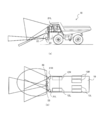
- FIG. 1 shows an external view of a dump truck which is a mine transport vehicle.
- FIG. 2 is a view showing a detection area of an external recognition sensor mounted on the dump truck according to the present embodiment, where (a) shows a side view and (b) shows a plan view.
- the dump according to the present embodiment may be a so-called manned dump truck that a driver rides and controls, or an autonomous traveling dump truck that autonomously travels without the driver boarding.
- a manned dump will be described as an example.
- a dump truck (hereinafter abbreviated as “dump”) 10 includes a frame 11 forming a main body, front wheels 12R, 12L and a rear wheel 13L (the right rear wheel 13R is not shown in FIG. 1), a frame 11 and a pair of left and right hoist cylinders (not shown) for rotating the load platform 14 in the vertical direction. And including.
- the front information of the frame 11 is provided with a driver's cab 15 in which the driver gets on.
- GPS antennas 16R and 16L for receiving GPS (Global Positioning System) radio waves are provided in front of the driver's seat.
- a building 17 for accommodating a radiator is provided on the front surface of the frame 11.
- the dump 10 includes a plurality of external recognition sensors for recognizing the surrounding environment of the dump 10 and sensors for collecting vehicle body information.
- the right camera 21R and the left camera 21L are used as the external recognition sensor A
- the laser range finder (LRF) 22 is used as the external recognition sensor B
- the Doppler radar (millimeter wave radar) 23 is used as the external recognition sensor C.
- the right camera 21R and the left camera 21L are provided at positions higher than the front right and left cabs 15 of the dump truck 10 (see FIG. 2A).
- the LRF 22 is above the building 17, and the millimeter wave radar 23 is at the building 17. It is provided on the lower side (see FIG. 2A).
- the right camera 21R and the left camera 21 are collectively referred to as a stereo camera 21.
- the millimeter wave radar 23 has a recognition range that reaches the farthest.
- the LRF 22 is closer to the dump 10 and has the widest recognition range in the vehicle width direction.
- the recognition range of the stereo camera 21 is at a position closest to the dump 10.
- the dump truck 10 includes a speed sensor (wheel rotation number detection sensor) of the dump truck 10 and a pedal operation amount sensor that detects a depression amount of the traveling pedal in the cab 15.
- the dump truck 10 includes a vehicle body controller 110 that performs vehicle body / running control of the dump truck 10 and a relay controller (electronic controller) 120.
- the vehicle body controller 110 is communicatively connected to each sensor via an in-vehicle communication network system and a relay controller (electronic controller) 120.
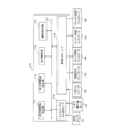
- FIG. 3 is a schematic configuration diagram showing the configuration of the in-vehicle communication network system.
- the in-vehicle communication network system 100 includes a vehicle body controller 110 that performs main control of the dump truck 10, a relay controller 120, an information display controller 130, a pump controller 140, an engine controller 150, and a brake controller 160.
- the sensor group 20, the monitor 30, the pump 40, the engine 50, and the brake 60 are configured to communicate with each other.
- the sensor group 20 includes a stereo camera 21, an LRF 22, a millimeter wave radar 23, a speed sensor 24, and a pedal operation amount sensor 25.
- the vehicle body controller 110, the relay controller 120, the information display controller 130, the pump controller 140, the engine controller 150, and the brake controller 160 are each an in-vehicle network communication line (for example, high-speed CAN: communication speed is less than 1 Mbps) 170 is connected.
- the types of CAN communication speed include 250 kbps, 500 kbps, and 1 Mbps.
- the fastest CAN is referred to as a high-speed CAN
- the slowest CAN is referred to as a low-speed CAN.
- the stereo camera 21 and the LRF 22 are connected to the relay controller 120 via a general-purpose high-speed communication protocol (for example, Ethernet (registered trademark): communication speed is less than 1 Gbps) 171, and raw data generated by each sensor. Is output to the relay controller 120.
- a general-purpose high-speed communication protocol for example, Ethernet (registered trademark): communication speed is less than 1 Gbps
- the relay controller 120 Since it is received by a network using a general-purpose high-speed communication protocol and then converted into processed data and then sent to the in-vehicle network communication line 170, even when the amount of raw data is larger than the standard of the in-vehicle network communication line 170, The occurrence of communication time delay can be suppressed.
- the relay controller 120 since the network using the general-purpose high-speed communication protocol 171 and the in-vehicle network communication line 170 are connected via the relay controller 120, the relay controller 120 performs protocol conversion even if the communication protocol of raw data and processing data is different. It can be carried out. Therefore, when a sensor is added or changed, the sensor can be easily added or changed without being restricted by the communication protocol of the in-vehicle network communication line 170.
- the millimeter wave radar 23 is connected to the relay controller 120 via a low-speed CAN 172 (communication speed: less than 250 Kbps), which is an in-vehicle communication network of a standard different from the in-vehicle communication network 170 between the controllers, and the raw data is transmitted.
- a low-speed CAN 172 communication speed: less than 250 Kbps
- the vehicle body controller 110 is connected to the speed sensor 24 via the communication line 173. Then, the detection value of the speed sensor 24 is input to the vehicle body controller 110 as a pulse signal.
- the vehicle body controller 110 is connected to the pedal operation amount sensor 25 via the communication line 174. Then, an analog signal indicating the depression amount of a pedal (not shown) detected by the pedal operation amount sensor 25 is input to the vehicle body controller 110.
- the information display controller 130 is connected to a monitor 30 installed in the cab 15 via a communication line 175. And the information display controller 130 is based on the alarm display signal and display control signal (digital signal) which were acquired from the vehicle body controller 110 via high-speed CAN, and the analog signal (NTSC signal: National Television System Committee) which shows a display content is shown. (Composite video signal conforming to the standard) is generated and output to the monitor 30.
- the pump controller 140 is connected to the pump 40 via the communication line 176. Then, the pump controller 140 controls the tilt angle control signal (analog signal) for controlling the tilt angle of the pump 40 based on the pump control signal (digital signal) acquired from the vehicle body controller 110 via the high-speed CAN. ) And output to the pump 40.
- the engine controller 150 is connected to the engine 50 via the communication line 177. Then, the engine controller 150 generates a rotation speed control signal (analog signal) for controlling the rotation speed of the engine 60 based on the engine control signal (digital signal) acquired from the vehicle body controller 110 via the high-speed CAN. Generated and output to the engine 50.
- the brake controller 160 is connected to the brake 60 via the communication line 178.
- the brake controller 160 generates a drive control signal (analog signal) for driving the brake 60 based on the braking signal (digital signal) acquired from the vehicle body controller 110 via the high-speed CAN. Drive.
- the brake 60 includes both a mechanical brake and a service brake.
- FIG. 4 is a block diagram illustrating a functional configuration of the relay controller.
- FIG. 5 is a diagram illustrating a road shoulder detection point calculation process.
- FIG. 6 is a diagram illustrating a road shoulder shape calculation process.
- the relay controller 120 includes an image processing block 121 that extracts a detection target from raw data from the stereo camera 21, and a road shoulder detection block 122 that performs road shoulder detection processing based on the raw data from the LRF 22.
- a moving obstacle detection unit 123 that detects a moving obstacle based on raw data from the millimeter wave data 23, an Ethernet interface (hereinafter referred to as “I / F”) 124, a low-speed CANI / F125, and a high-speed CANI / F126.
- I / F Ethernet interface
- the Ethernet I / F 124 and the low-speed CAN I / F 125 correspond to the input interface
- the high-speed CAN I / F 126 corresponds to the output interface.
- the image processing block 121 includes a correlation processing unit 121a, a noise processing unit 121b, and a target image extraction unit 121c.
- the road shoulder detection block 122 includes a road shoulder detection point calculation unit 122a and a road shoulder shape detection unit 122b.
- the image processing block 121, the road shoulder detection block 122, and the moving obstacle detection unit 123 are configured by an integrated circuit that realizes the function of each block.
- the relay controller 120 is configured to include hardware including a CPU, RAM, ROM, and HDD, and software that realizes the functions of the above blocks, and each function is loaded and executed by the software. It may be configured to be realized.
- the Ethernet I / F 124, the low-speed CAN I / F 125, and the high-speed CAN I / F 126 are configured to include connectors and driver software that conform to each communication standard.
- the stereo camera 21 and the LRF 22 are connected to the Ethernet I / F 124, and raw data is input from each.
- a millimeter wave radar 23 is connected to the low-speed CANI / F 125.
- the high-speed CAN I / F 126 is connected to the vehicle body controller 110 and the information display controller 130 via the in-vehicle network communication line 170.
- the correlation processing unit 121a combines the raw data output from each of the right camera 21R and the left camera 21L based on the correlation of the subject in the raw data output from each of the right camera 21R and the left camera 21L with parallax. Thus, one moving image (hereinafter referred to as “composite image data”) is generated.
- the noise processing unit 121b performs time-series correlation processing on each frame constituting the composite image data, and when a subject whose correlation value is equal to or less than a predetermined threshold is captured in the composite image data, A process of determining that this is an object different from the front obstacle, that is, noise is performed.
- the target image extraction unit 121c extracts, as target image data, a region where the detection target is imaged from the composite image data after the noise is deleted. For example, when the detection target is defined as a dump that travels ahead, a contour extraction process is performed based on the color information of the same color as the dump in the composite image data, and data and pattern matching indicating the back shape of the dump stored in advance are performed. To determine whether the area is a dump area.
- the extracted image data indicating the dump area is output to the vehicle body controller 110 via the high-speed CAN I / F 126.
- the target image extraction unit 121c acquires coordinate system information indicating at least one of the attachment position and angle (attachment posture) of the stereo camera 21 from the vehicle body controller 110, and uses the coordinate system of the imaged dump as the vehicle body coordinates. You may perform the process converted into a system. Further, when the size of the dump to be detected as an obstacle is known, the relative position (distance) between the dump 10 and the dump to be detected, the area of the dump area and the number of pixels at that position are measured in advance. The correction data may be generated and stored. Then, the relative position (distance) between the dump 10 and the imaged dump may be calculated based on a comparison between the imaged dump area and the correction data.
- the coordinates converted according to the coordinate system of the vehicle body and the relative position (distance) are the processing data.
- the target image extraction unit 121c takes part of the processing of the front obstacle determination unit 111 of the vehicle body controller 110, which will be described later, and the processing load on the vehicle body controller 110 can be reduced.
- the target image extraction unit 121c acquires coordinate system information indicating at least one of the mounting position of the stereo camera 21 and the mounting posture (pan, tilt) of the sensor, and the relative position of the obstacle with respect to the dump 10 is determined. Processing data converted into a coordinate system may be generated. Thereby, since the data format of the machining data is converted into the coordinate system of the vehicle body controller 110, it is not necessary for the vehicle body controller controller 110 to perform coordinate conversion processing from raw data when executing the control processing. The processing load on the controller 110 can be reduced.
- the low-speed CANI / F 126 is connected to each of the LRFs 22 via the Ethernet 161, and raw data generated by the LRFs 22, more specifically, data defined by the two-dimensional point cloud is input to the relay controller 120.
- the road shoulder detection block 122 includes a road shoulder detection point calculation unit 122a and a road shoulder shape detection unit 122b.
- the road shoulder detection point calculation unit 122a detects road shoulders located on the left and right sides of the dump truck 10 based on the data defined by the two-dimensional point cloud.
- the road shoulder shape detection unit 122b detects the shape of the road shoulder using a vector.
- the road shoulder detection point calculation unit 122a detects a two-dimensional coordinate (x, y) as a road shoulder detection point.
- the road shoulder detection point calculation unit 122a is the closest point P RO (x RO , y RO ) of the road shoulder on the right side of the dump 10 and the farthest point in the R_LRF in the recognition region of the LRF 22.
- P RO (x Rn , y Rn ) the closest point P LO (x LO , y LO ) among the road shoulders on the left side
- the road shoulder detection point calculation unit 122a detects, for example, an inflection point of the distance to the reflection point of the light output from the LRF 22 as a road shoulder detection point candidate, and the closest point on each of the left and right sides of the road shoulder detection point candidates. The farthest point may be determined as a road shoulder detection point. These two-dimensional coordinates of the road shoulder detection points correspond to the machining data and are output to the vehicle body controller 110 via the high-speed CANI / F 126.
- the road shoulder shape detection unit 122b represents the traveling direction and position of the road shoulder by a vector.
- the road shoulder shape detection unit 122 b has the closest point P RO (x RO , y RO ) and the farthest point P Rn ( x Rn , y Rn ) and a relay point P Ri (x Ri , y Ri ) therebetween are calculated, and a vector whose start point is P RO (x RO , y RO ) and whose end point is P Ri (x Ri , y Ri ) And a vector having a starting point P Ri (x Ri , y Ri ) and an end point P Rn (x Rn , y Rn ).
- the number of vectors is not limited to two.
- four relay points are provided, and a total of five vectors are calculated to identify the shoulder shape.
- These vectors for specifying the road shoulder shape correspond to the machining data, and are output to the vehicle body controller 110 via the high-speed CANI / F 126.
- the moving obstacle detecting unit 123 calculates the relative speed of the obstacle using the relative position of the dump 10 and the obstacle and the Doppler effect based on the raw data of the millimeter wave radar 23, and these are processed data. .
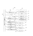
- FIG. 7 is a block diagram showing a functional configuration of the vehicle body controller.
- the vehicle body controller includes a front obstacle determination unit 111, a side obstacle determination unit 112, a travel control unit 113, an alarm instruction unit 114, an analog / digital signal I / F 115, and a high-speed CAN I / F 116. And these are connected to each other via a bus 117.
- a speed sensor 24 and a pedal operation amount sensor 25 are connected to the analog / digital signal I / F 116.
- the raw data of these sensors is used for calculating the vehicle speed. For example, in the determination of the possibility of collision in the forward obstacle determination unit 111, the calculated value is used as the speed of the host vehicle.
- the forward obstacle determination unit 111, the side obstacle determination unit 112, the travel control unit 113, and the alarm instruction unit 114 are also configured by cooperation of an integrated circuit, the hardware described above, and software that realizes the functions of the above blocks. May be.
- the forward obstacle determination unit 111 determines whether an obstacle is imaged in the processing data (image data of the target object) generated from the raw data of the stereo camera 21. When an obstacle is imaged, the forward obstacle determination unit 111 calculates the position (relative coordinate value viewed from the vehicle body) and size of the detection object, measures the distance to the front obstacle, and detects a collision risk. Determine sex. Further, the front obstacle determination unit 111 acquires the position of the detection target (relative coordinate value viewed from the vehicle body) and the relative speed from the processing data generated from the raw data of the millimeter wave radar 23, and determines the possibility of collision. judge. If it is determined that there is a possibility of collision, the determination result is output to the warning instruction unit 114. The alarm instruction unit 114 outputs an alarm signal to the information display controller 130, displays a forward collision alarm message on the monitor 30, and issues an alarm to the operator. Furthermore, a braking request signal including the distance to the front obstacle may be output to the traveling control unit 113.
- the side obstacle determination unit 112 performs a side obstacle determination process for detecting the approach to the road shoulder or wall located on the side of the dump 10 based on the processing data generated from the raw data of the LRF 22. Specifically, the side obstacle determination unit 112 calculates the position (relative coordinate value) of the closest detection point from the dump 10, and this is equal to or less than the distance threshold value that defines the closest approach distance to the side obstacle. It is determined whether it is. When the distance to the detection point is equal to or less than the distance threshold, the alarm instruction unit 114 outputs an alarm signal to the information display controller 130. Upon receiving the warning signal, the information display controller 130 displays a roadside deviation warning message on the monitor 30 and issues a warning to the operator.
- the traveling control unit 113 calculates a necessary braking amount based on the distance to the front obstacle included in the braking request signal, and outputs a braking instruction signal to the brake control controller 160.
- the brake controller 160 operates the brake according to the braking instruction signal. Thereby, the collision with a front obstacle is suppressed.
- This raw data is constituted by a three-dimensional (x, y, z) point cloud (point cloud).
- the communication speed S1 necessary for transmitting raw data to the relay controller 120 can be expressed by the following equation (1).
- This raw data is composed of a two-dimensional (x, y) point cloud (point cloud).
- the communication speed S2 necessary for transmitting raw data to the relay controller 120 can be expressed by the following equation (2).
- S2 coordinate point (X, Y) ⁇ angle range ⁇ angle resolution ⁇ scan frequency (2)
- each camera LRF 22 and the relay controller 120 are connected by Ethernet to output data.
- This raw data includes a representative position and a relative speed of a two-dimensional detection object.
- the communication speed S3 necessary for transmitting raw data to the relay controller 120 can be expressed by the following equation (3).
- S3 (detection object ID + coordinate point (X, Y) + relative speed V) ⁇ number of detections ⁇ output frequency (3)
- the image processing block 121 and the road shoulder detection block 122 of the relay controller 120 convert data (processing data) that can be used by the vehicle body controller 110 in accordance with the output value and usage of each sensor. Therefore, these functional blocks correspond to a data conversion unit.
- Data conversion methods include extracting a part from the point cloud, specifying representative points calculated by grouping the point cloud, and vectors calculated from the positional relationship of the point cloud (those with reduced dimensions: for example, from space A plane, a line segment from the plane, and a line segment to a point). There can also be any of these or any combination thereof.
- Raw data from each of the cameras 21R and 21L is converted into processing data indicating the position and size of the detection target (obstacle).
- the communication speed S4 in this case can be expressed by the following equation (4).
- S4 (detection object ID + coordinate point (X, Y, Z) + object size (W, H)) ⁇ number of detections ⁇ output frequency (4)
- the communication speed of Expression (4) ′ is 90 kbps, so that the processed data can be transmitted at a lower communication speed.
- the coordinate values correspond to representative points calculated by grouping point groups.
- the raw data of LRF (2D LIDAR) is converted into processing data indicating a road shoulder detection point.
- the communication speed S5 in this case is expressed by the following equation (5).
- S5 coordinate point (X, Y) ⁇ two left and right points ⁇ output frequency (5)
- the communication speed S6 when the raw data of the LRF 22 is converted into a road shoulder shape vector (point sequence) is expressed by the following equation (6).
- S6 coordinate point (X, Y) ⁇ maximum number of vectors ⁇ left / right ⁇ output frequency (6)
- raw data composed of a large amount of digital signals output from a sensor for example, digital data composed of point groups of two-dimensional or three-dimensional coordinates
- Process data with less data than data is generated.
- the communication time during which the machining data is transmitted from the relay controller to the vehicle body controller can be further shortened.
- the data format of the machining data corresponds to the vehicle body controller, it is not necessary for the vehicle body controller to perform processing to convert from raw data to machining data when executing the control process, and the processing load of the vehicle body controller Can be lowered.
- the relay controller when converting to machining data in the relay controller, it can be converted into a format that conforms to the protocol of the existing in-vehicle communication network system, so it is possible to easily add or change sensors.
- FIG. 8 is a diagram illustrating a connection state of the relay controller 120 in the second embodiment.
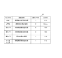
- FIG. 9 is an example of a table that defines conversion processing rules stored in the relay controller.
- the relay controller 120a As shown in FIG. 8, in the relay controller 120a according to the second embodiment, as an external recognition sensor A, a camera 21B that captures the rear of the vehicle body of the dump truck 10 is further connected to the Ethernet 1 / F 121. Further, the external recognition sensor B includes a further LRF 22a.
- the relay controller 120a includes a conversion processing rule storage unit 200 that stores a conversion table 90 (see FIG. 9) that defines conversion processing for each sensor.
- the conversion table 90 is conversion processing information that defines sensor identification information (sensor ID) that uniquely identifies a sensor and conversion processing that is executed on raw data generated from each sensor in association with each other. It is stored in the processing rule storage unit 200.
- the relay controller 120a corresponds to the CAN protocol, refers to the sensor ID that is the generation source added to the raw data, refers to the sensor ID and the conversion table 90, and refers to the raw data A conversion process corresponding to the generation source is executed.
- FIG. 9 The relay controller 120a corresponds to the CAN protocol, refers to the sensor ID that is the generation source added to the raw data, refers to the sensor ID and the conversion table 90, and refers to the raw data A conversion process corresponding to the generation source is executed.
- LRF1 reference numeral 22
- LRF2 reference numeral 22a
- a shoulder shape detection process is performed.
- the rear camera (not shown) performs a vehicle stop detection process.
- the relay controller 120a can calculate the conversion table 90 and perform different conversion processes for each sensor. In particular, even with the same type of sensor, different conversion processes can be performed to generate processed data in different data formats.
- the relay controller 120a executes / does not execute the processes of the functional blocks of the relay controller 120a, that is, the image processing block 121, the road shoulder detection point calculation unit 122, the road shoulder shape detection unit 123, and the forward moving obstacle detection processing unit 124.
- a selector switch 210 may be provided.
- the execution state / non-execution setting state by the selector switch 210 is stored as the value of the execution flag of the conversion table 90. If the selector switch 210 is set to execute, “1” is input to the execution flag record, and if not set to “0”, “0” is input to the execution flag record.
- the output destination of raw data or processed data is input to the output destination record of the conversion table 90.
- the output value of the output destination record is updated in conjunction with the execution flag input.
- the execution flag is “1”
- the output destination is a value “110” indicating output to the vehicle body controller 110.
- the execution flag is “0”
- the output destination is output to the information display controller 130.
- a value “130” indicating that there is no output destination or “NULL” indicating that there is no output destination is input.
- the front obstacle may be detected only by the millimeter wave radar while displaying a through image on the monitor 30 using the low data of the stereo camera 21 to compensate for the driver's blind spot.
- the output destination is changed to “130”.
- the correlation processing unit 121 a generates composite image data based on the raw data input from the relay controller 120, the composite image data is output to the information display controller 120, and the stereo camera composite image is displayed on the monitor 30.
- You may comprise.
- the relay controller 120a may be configured to output the raw data of the right camera 21R and the left camera 21L to the information display controller 130 as they are, and to display the through images from both cameras on the monitor 30, respectively.
- the execution flag of the road shoulder shape detection process is set to “0”, even if the low data of LRF2 (symbol 22a) is input to the relay controller 120a, the conversion process is not performed anywhere. May not be output.
- the selector switch 210 arbitrarily sets the execution of the conversion process using the raw data of the sensor to reduce the load related to the conversion process of the relay controller 120a or to reduce the amount of data flowing through the in-vehicle network communication line 170. Can do.
- the operation of the selector switch 210 may be received from a user interface (not shown) such as a soft switch displayed on a touch panel or a monitor. Further, the conversion process determined for each sensor may always be executed without mounting the selector switch 210. In this case, the record defining the execution flag and output destination of the conversion table 90 is not necessary.
- the raw data conversion process can be changed for each sensor, even when there are a plurality of sensors of the same type, it is possible to selectively execute the process according to the traveling state of the dump truck 10. it can.
- a sensor with a small amount of raw data such as the millimeter wave radar 23 may be directly connected to the in-vehicle network communication line 170 as shown in FIG.
- a mining transport vehicle has been described as an example of a construction machine.
- a sensor mounted on a vehicle body and a vehicle body controller are connected by CAN, such as a hydraulic excavator and a wheel loader. If it exists, this invention can be applied and the kind of construction machine is not ask
- Dumper construction machine
- vehicle body controller body control device
- Relay controller electronic control unit
Landscapes
- Engineering & Computer Science (AREA)
- Mechanical Engineering (AREA)
- Mining & Mineral Resources (AREA)
- Civil Engineering (AREA)
- General Engineering & Computer Science (AREA)
- Structural Engineering (AREA)
- Small-Scale Networks (AREA)
- Traffic Control Systems (AREA)
Abstract
多量のデジタル信号を出力するセンサを既存の車載通信ネットワークシステムに接続する際の通信時間のロスをより削減できる電子制御装置及び車載通信ネットワークシステムを提供する。 建設機械の車体に搭載されたセンサ21、22、34及び建設機械の制御を行う車体制御装置110の間に接続される電子制御装置120であって、センサからローデータの入力を受ける入力インターフェース124、125と、ローデータに対して車体制御装置110において用いられるデータ形式に変換する処理を実行し、加工データを生成するデータ変換部121,122,123と、車体制御装置110に対して、加工データを出力する出力インターフェース126と、を備える。
Description
本発明は電子制御装置及び車載通信ネットワークシステムに係り、特に建設機械の車体に設けられたセンサから車体の制御装置にデータを転送する際の通信量を削減する技術に関する。
ショベル、ダンプなどの建設機械では、多種多様なセンサにより車体内外の状態を把握している。各センサからの情報は車体に備えられた複数のコントローラ(制御装置)のいずれかに入力される。これら複数のコントローラ群は1つまたは複数の通信プロトコルに基づいて相互に接続され、車載通信ネットワークシステムを構成する。各センサから入力された情報は、各コントローラ上で処理・加工され、その結果を他のコントローラと送受信することで、車体アクチュエータ制御や車体状態監視に用いられる。
車体コントローラに関する先行技術として、特許文献1には、作業機械に設けられた複数のセンサと、センサの検出結果に基いて制御処理を行うコントローラとの間の配線を簡素化するため、車載通信ネットワークシステム上に、複数センサからのアナログ信号をデジタル信号に変換・フィルタリングしてCAN(Control Area Network)に出力するコンバータを備える構成が開示されている。
また特許文献2には、通信プロトコル仕様の異なるコントローラが混在している建設機械でも、各コントローラ相互間でシリアル通信を可能にするため、通信プロトコルAのコントローラ群と、通信プロトコルBのコントローラ群の間に、通信プロトコルA,B両方を備えた情報管理用コントローラを設け、データを収集・加工・記憶する構成が開示されている。
センサから出力されるアナログ信号をデジタル信号に変換してCANに出力するが、このデジタル信号を受信した車体コントローラは、センサから取得したデータを車体コントローラにおいて実行される制御処理に合ったデータ形式に変換する。この際、データ形式を変換するための処理負荷が車体コントローラにかかるが、特にセンサが複数あり、車体コントローラにおいて異なる制御処理を同時に実行する際には、処理負荷が大きくなるという課題がある。この点につき、特許文献1,2には何ら言及されていない。
本発明は、上記の実情に鑑みてなされたものであり、センサから出力されるデータを基に車体制御を行う車体制御装置の処理負荷を削減できる電子制御装置及び車載通信ネットワークシステムを提供することを目的とする。
上記課題を解決するために、本発明は建設機械の車体に搭載されたセンサ及び前記建設機械の制御を行う車体制御装置の間に接続される電子制御装置であって、前記センサから、当該センサが生成したローデータの入力を受ける入力インターフェースと、前記ローデータに対して前記車体制御装置において用いられるデータ形式に変換する処理を実行し、加工データを生成するデータ変換部と、前記車体制御装置に対して、前記加工データを出力する出力インターフェースと、を備えることを特徴とする。
本発明によれば、多量のデジタル信号を出力するセンサを既存の車載通信ネットワークシステムに接続する際の通信時間のロスをより削減できる電子制御装置及び車載通信ネットワークシステムを提供することができる。上記した以外の課題、構成及び効果は、以下の実施形態の説明により明らかにされる。
以下、本発明の実施の形態を図面に基づいて詳細に説明する。なお、実施の形態を説明するための全図において、同一の機能を有する部材には同一または関連する符号を付し、その繰り返しの説明は省略する。また、以下の実施の形態では、特に必要なとき以外は同一または同様な部分の説明を原則として繰り返さない。
まず、図1及び図2を参照して本実施形態に係る車両の外観図について説明する。図1は、鉱山用運搬車両であるダンプトラックの外観図を示す。図2は本実施形態に係るダンプトラックに搭載される外界認識センサの検出エリアを示す図であって、(a)は側面図を示し、(b)は平面図を示す。本実施形態に係るダンプは、運転手が搭乗して操縦する、所謂有人ダンプでもよいし、運転手が搭乗することなく自律走行する自律走行ダンプトラックでもよい。以下では、有人ダンプを例に挙げて説明する。
図1に示すように、ダンプトラック(以下ダンプと略記する)10は、本体を形成するフレーム11と、前輪12R、12L及び後輪13L(右側後輪13Rは図1では不図示)と、フレーム11の後方部分に設けられたヒンジピン(図示せず)を回動中心として上下方向に回動可能な荷台14と、この荷台14を上下方向に回動させる左右一対のホイストシリンダ(図示せず)と、を含む。フレーム11の前方情報には、運転手が搭乗する運転室15が備えられる。そして運転席前方に、GPS(Global Positioning System)電波を受信するためのGPSアンテナ16R、16Lが備えられる。フレーム11の前面にはラジエターを収容する建屋17が備えられる。
ダンプ10は、ダンプ10の周辺環境を認識するための外界認識センサや、車体情報を収集するためのセンサを複数備える。例えば、本実施形態では外界認識センサAとして右カメラ21R及び左カメラ21Lと、外界認識センサBとしてレーザーレンジファインダ(LRF)22と、外界認識センサCとしてのドップラ式レーダ(ミリ波レーダ)23を備える。右カメラ21R、及び左カメラ21Lはダンプ10の前面右側及び左側の運転室15よりも高い位置に備えられる(図2(a)参照)LRF22は建屋17の上側、ミリ波レーダ23は建屋17の下側に備えられる(図2(a)参照)。以下、右カメラ21R及び左カメラ21を総称してステレオカメラ21という。
図2(b)を参照して外界認識センサA、B、Cの認識範囲について説明する。まず、ミリ波レーダ23が最も遠方まで届く認識範囲を有する。次いでLRF22がよりダンプ10により近く、かつ車幅方向には最も広い認識範囲を有する。そして、ステレオカメラ21の認識範囲が最もダンプ10に近い位置にある。
また図1では図示を省略するものの、ダンプ10は、ダンプトラック10の速度センサ(車輪回転数検出センサ)、運転室15の内部にある走行ペダルの踏込量を検出するペダル操作量センサを備える。
更に、ダンプトラック10は、ダンプ10の車体・走行制御を行う車体制御コントローラ110及び中継コントローラ(電子制御装置)120を備える。車体制御コントローラ110は、車載通信ネットワークシステム及び中継コントローラ(電子制御装置)120を介して、各センサと通信接続される。
図3を参照して、ダンプトラック10に搭載される車載通信ネットワークシステムについて説明する。図3は、車載通信ネットワークシステム構成を示す概略構成図である。
図3に示すように車載通信ネットワークシステム100は、ダンプ10の主制御を行う車体制御コントローラ110、中継コントローラ120、情報表示コントローラ130、ポンプ制御コントローラ140、エンジン制御コントローラ150、及びブレーキ制御コントローラ160、センサ群20、モニタ30、ポンプ40、エンジン50、及びブレーキ60が互いに通信接続されて構成される。
センサ群20には、ステレオカメラ21、LRF22、ミリ波レーダ23、速度センサ24、及びペダル操作量センサ25が含まれる。
車体制御コントローラ110と、中継コントローラ120、情報表示コントローラ130、ポンプ制御コントローラ140、エンジン制御コントローラ150及びブレーキ制御コントローラ160の其々とは、車載ネットワーク通信ライン(例えば高速CAN:通信速度は1Mbps未満)170を介して接続されている。CANの通信速度の種類には、250kbps、500kbps、及び1Mbpsがあり、本実施形態では最速のCANを高速CAN、最も低速のCANを低速CANと称する。
センサ群20のうち、ステレオカメラ21及びLRF22は汎用高速通信プロトコル(例えばイーサネット(Ethernet(登録商標):通信速度は1Gbps未満)171を介して中継コントローラ120と接続され、各センサが生成するローデータが中継コントローラ120に出力される。
これにより、中継コントローラ120から車体制御コントローラ110までの通信経路の規格に応じた通信速度では通信時間の遅延が発生する可能性があるローデータがセンサから出力される場合に、中継コントローラ120までは汎用高速通信プロトコルを用いたネットワークで受信し、その後加工データに変換してから車載ネットワーク通信ライン170に流すので、ローデータのデータ量が車載ネットワーク通信ライン170の規格に対して大きい場合にも、通信時間の遅延の発生を抑止できる。また、中継コントローラ120を介して汎用高速通信プロトコル171を用いたネットワークと車載ネットワーク通信ライン170とを接続するので、ローデータと加工データとの通信プロトコルが異なっていても中継コントローラ120でプロトコル変換を行うことができる。そのため、センサの追加や変更時に、車載ネットワーク通信ライン170の通信プロトコルによる制約を受けずセンサの追加・変更が容易にできる。
ミリ波レーダ23は、各コントローラ間の車載通信ネットワーク170とは異なる規格の車載通信ネットワークである低速CAN172(通信速度:250Kbps未満)を介して中継コントローラ120に接続され、そのローデータが送られる。
更に車体制御コントローラ110は、通信線173を介して速度センサ24と接続される。そして、速度センサ24の検出値がパルス信号として車体制御コントローラ110に入力される。
また、車体制御コントローラ110は、通信線174を介してペダル操作量センサ25と接続される。そしてペダル操作量センサ25が検出したペダル(不図示)の踏込量を示すアナログ信号が、車体制御コントローラ110に入力される。
情報表示コントローラ130は、通信線175を介して運転室15に設置されたモニタ30が接続される。そして、情報表示コントローラ130は、車体制御コントローラ110から高速CANを介して取得した警報表示信号や表示制御信号(デジタル信号)に基づいて、表示内容を示すアナログ信号(NTSC信号:National Television System Committeeの規格に準拠したコンポジット映像信号)を生成し、モニタ30に対して出力する。
ポンプ制御コントローラ140は、通信線176を介してポンプ40に接続される。そして、ポンプ制御コントローラ140は、車体制御コントローラ110から高速CANを介して取得したポンプ制御信号(デジタル信号)に基づいて、ポンプ40の傾転角を制御するための傾転角制御信号(アナログ信号)を生成し、ポンプ40に対して出力する。
エンジン制御コントローラ150は、通信線177を介してエンジン50に接続される。そして、エンジン制御コントローラ150は、車体制御コントローラ110から高速CANを介して取得したエンジン制御信号(デジタル信号)に基づいて、エンジン60の回転数を制御するための回転数制御信号(アナログ信号)を生成し、エンジン50に対して出力する。
ブレーキ制御コントローラ160は、通信線178を介してブレーキ60に接続される。そして、ブレーキ制御コントローラ160は、車体制御コントローラ110から高速CANを介して取得した制動信号(デジタル信号)に基づいて、ブレーキ60を駆動させるための駆動制御信号(アナログ信号)を生成し、ブレーキ60を駆動する。なお、ブレーキ60には、機械ブレーキ及びサービスブレーキの双方が含まれる。
次に図4乃至図6を参照して、中継コントローラ120の内部構成について説明する。図4は、中継コントローラの機能構成を示すブロック図である。図5は、路肩検出点の算出処理を示す図である。図6は、路肩形状算出処理を示す図である。
図4に示すように中継コントローラ120は、ステレオカメラ21からのローデータから、検出対象物を抽出する画像処理ブロック121と、LRF22からのローデータを基に路肩の検出処理を行う路肩検出ブロック122と、ミリ波データ23からのローデータを基に移動障害物の検出を行う移動障害物検出部123と、イーサネットインターフェース(以下「I/F」)124、低速CANI/F125、及び高速CANI/F126を含み、これらがバス127を介して互いに接続されて構成される。イーサネットI/F124、低速CANI/F125が入力インターフェースに相当し高速CANI/F126が出力インターフェースに相当する。
画像処理ブロック121は、相関処理部121a、ノイズ処理部121b、対象画像抽出部121cを含む。
また、路肩検出ブロック122は、路肩検出点算出部122a及び路肩形状検出部122bを含む。
画像処理ブロック121、路肩検出ブロック122、及び移動障害物検出部123は、各ブロックの機能を実現する集積回路により構成される。また中継コントローラ120をCPU、RAM、ROM、HDDを含むハードウェアと、上記ブロックの機能を実現するソフトウェアとを含んで構成し、このソフトウェアがハードウェアにロード、実行されることにより、各機能が実現されるように構成されてもよい。
イーサネットI/F124、低速CANI/F125及び高速CANI/F126は、各通信規格に適合したコネクタ、及びドライバソフトを含んで構成される。
イーサネットI/F124にはステレオカメラ21及びLRF22が接続され、それぞれからローデータが入力される。低速CANI/F125には、ミリ波レーダ23が接続される。高速CANI/F126は、車載ネットワーク通信ライン170を介して車体制御コントローラ110及び情報表示コントローラ130に接続される。
相関処理部121aは、視差がある右カメラ21R及び左カメラ21Lのそれぞれから出力されるローデータ内の被写体の相関を基に、右カメラ21R及び左カメラ21Lのそれぞれから出力されるローデータを合成して1つの動画像(以下「合成画像データ」という)を生成する。
ノイズ処理部121bは、合成画像データを構成する各フレームに対し、時系列方向の相関処理を行い、合成画像データ内に相関値が予め定められた閾値以下の被写体が撮像されている場合に、これを前方障害物とは異なる物体である、すなわちノイズであると判定して削除する処理を行う。
対象画像抽出部121cは、ノイズ削除後の合成画像データから検出対象物が撮像された領域を対象画像データとして抽出する。例えば、検出対象物を、前方を走行するダンプと定義する場合、合成画像データ内のダンプと同色の色情報を基に輪郭抽出処理を行い、予め記憶したダンプの背面形状を示すデータとパターンマッチングを行ってダンプ領域であるかを判別して抽出してもよい。抽出したダンプ領域を示す画像データは、高速CANI/F126を経由して車体制御コントローラ110へ出力される。
また対象画像抽出部121cは、車体制御コントローラ110からステレオカメラ21の取付位置及び角度(取付姿勢)の少なくとも一つを示す座標系情報を取得し、撮像されたダンプの座標系を、車体の座標系に変換する処理を行ってもよい。更に、障害物として検出するダンプの大きさが既知である場合、予めダンプ10と検出対象のダンプとの相対位置(距離)、及びその位置におけるダンプ領域の面積やピクセル数とを測定しておき、更正データを生成・記憶しておいてもよい。そして、撮像されたダンプ領域と更正データとの比較を基に、ダンプ10と撮像されたダンプとの相対位置(距離)を算出してもよい。この場合、車体の座標系に合わせて変換した座標や、相対位置(距離)が、加工データとなる。これにより、後述する車体制御コントローラ110の前方障害物判定部111の処理の一部を対象画像抽出部121cが担うこととなり、車体制御コントローラ110の処理負荷を下げることができる。
また、対象画像抽出部121cは、ステレオカメラ21の取り付け位置及びセンサの取り付け姿勢(パン、チルト)の少なくとも一つを示す座標系情報を取得し、障害物のダンプ10に対する相対位置をダンプ10の座標系に変換した加工データを生成してもよい。これにより、加工データのデータ形式は車体制御コントローラ110の座標系に変換されているので、車体制御コントローラ110が制御処理を実行するに当たり、ローデータからの座標変換処理をする必要がなく、車体制御コントローラ110の処理負荷を下げることができる。
低速CANI/F126は、LRF22のそれぞれとイーサネット161を介して接続され、LRF22が生成したローデータ、より具体的には2次元ポイントクラウドにより定義されたデータが中継コントローラ120へ入力される。
路肩検出ブロック122は、路肩検出点算出部122a及び路肩形状検出部122bを含む。路肩検出点算出部122aは、2次元ポイントクラウドにより定義されたデータを基に、ダンプ10の左右両側に位置する路肩を検出する。また、路肩形状検出部122bは、路肩の形状を、ベクトルを用いて検出する。
路肩検出点算出部122aは、2次元座標(x、y)を路肩検出点として検出する。図5の例では、路肩検出点算出部122aは、LRF22の認識領域内R_LRFにおいて、ダンプ10の右側にある路肩のうちの最も近い点PRO(xRO,yRO)、最も遠いである点PRO(xRn,yRn)、左側にある路肩のうちの最も近い点PLO(xLO,yLO)、最も遠い点PLn(xLn,yLn)の合計4点を検出する。路肩検出点算出部122aは、例えばLRF22から出力される光の反射点までの距離の変曲点を路肩検出点候補として検出し、それらの路肩検出点候補の内、左右各側において最も近い点及び最も遠い点を路肩検出点として決定してもよい。これら路肩検出点の2次元座標が加工データに相当し、高速CANI/F126を経由して車体制御コントローラ110へ出力される。
路肩形状検出部122bは、路肩の走行方向及び位置をベクトルにより表す。図6の例では、路肩形状検出部122bは、LRF22の認識領域内R_LRFにおいて、ダンプ10の右側にある路肩のうちの最も近い点PRO(xRO,yRO)、最も遠い点PRn(xRn,yRn)、及びその間の中継点PRi(xRi,yRi)を算出し、始点がPRO(xRO,yRO)、終点がPRi(xRi,yRi)のベクトルと、始点がPRi(xRi,yRi)、終点がPRn(xRn,yRn)のベクトルとの二つを算出する。
ベクトル数は二つに限らない。例えば図6の左側路肩の形状は、中継点を4つ設け、合計五つのベクトルを算出して路肩形状を特定する。これら路肩形状を特定するためのベクトルが加工データに相当し、高速CANI/F126を経由して車体制御コントローラ110へ出力される。
移動障害物検出部123は、ミリ波レーダ23のローデータを基に、ダンプ10と障害物との相対位置、及びドップラ効果を用いて障害物の相対速度を算出し、これらが加工データとなる。
次に、図7を参照して車体制御コントローラ110の内部構成について説明する。図7は、車体制御コントローラの機能構成を示すブロック図である。
図7に示すように車体制御コントローラは、前方障害物判定部111、側方障害物判定部112、走行制御部113、警報指示部114、アナログ・デジタル信号I/F115、及び高速CANI/F116を含み、これらがバス117を介して互いに接続されて構成される。アナログ・デジタル信号I/F116には速度センサ24及びペダル操作量センサ25が接続される。これらのセンサのローデータは、車速の算出に用いられる。そして、例えば前方障害物判定部111における衝突可能性の判定において、自車両の速度として算出値が用いられる。
前方障害物判定部111、側方障害物判定部112、走行制御部113、警報指示部114も、集積回路や既述のハードウェア及び上記ブロックの機能を実現するソフトウェアが協働することで構成されてよい。
前方障害物判定部111は、ステレオカメラ21のローデータから生成した加工データ(対象物の画像データ)に障害物が撮像されているかを判定する。障害物が撮像されている場合、前方障害物判定部111は検出対象物の位置(車体から見た相対的な座標値)及びサイズを算出し、前方障害物までの距離を測定し、衝突危険性を判定する。また、前方障害物判定部111は、ミリ波レーダ23のローデータから生成した加工データから検出対象物の位置(車体から見た相対的な座標値)と相対速度を取得し、衝突可能性を判定する。衝突可能性ありと判断された場合は、判定結果を警報指示部114に出力する。警報指示部114は、情報表示コントローラ130に対して警報信号を出力し、モニタ30に前方衝突警報メッセージを表示してオペレータに警報を発する。更に、走行制御部113に対して前方障害物までの距離を含む制動要求信号を出力してもよい。
側方障害物判定部112は、LRF22のローデータから生成した加工データを基に、ダンプ10側方に位置する路肩や壁への接近を検出するための側方障害物判定処理を行う。具体的には、側方障害物判定部112は、ダンプ10から最も近い検出点の位置(相対的な座標値)を算出し、これが側方障害物との最接近距離を規定した距離閾値以下であるかを判定する。検出点までの距離が距離閾値以下の場合に、警報指示部114は、情報表示コントローラ130に対して警報信号を出力する。情報表示コントローラ130は、警報信号を受け取ると、モニタ30に路肩逸脱警報メッセージを表示してオペレータに警報を発する。
走行制御部113は、制動要求信号に含まれる前方障害物まで距離に基いて必要な制動量を算出し、制動指示信号をブレーキ制御コントローラ160に対して出力する。ブレーキ制御コントローラ160は制動指示信号に従ってブレーキを作動させる。これにより、前方障害物との衝突を抑止する。
次に、外界認識センサが出力するローデータデータ量及び通信速度例について説明する。
まずカメラ21R、21Lの其々からのローデータについて説明する。このローデータは、3次元(x,y,z)のポイントクラウド(点群)により構成される。この場合に中継コントローラ120へローデータを送信するために必要な通信速度S1は、下式(1)により表せる。
S1=座標点(X,Y,Z)×(画像幅W×画像高さH)×fps・・・(1)
例えば、画像サイズが(W, H)=(640, 480)、座標値が各2byte、フレームレートが15fpsの場合、各値を式(1)に代入すると、
(X,Y,Z):6byte×640×480×30=210Mbps・・・(1)’
となり、210Mbps以上の通信速度が必要となる。そこで、イーサネットで各カメラ21R、21Lと中継コントローラ120とを接続し、ローデータを出力する。
(X,Y,Z):6byte×640×480×30=210Mbps・・・(1)’
となり、210Mbps以上の通信速度が必要となる。そこで、イーサネットで各カメラ21R、21Lと中継コントローラ120とを接続し、ローデータを出力する。
次にLRF22からのローデータについて説明する。このローデータは、2次元(x,y)のポイントクラウド(点群)により構成される。この場合に中継コントローラ120へローデータを送信するために必要な通信速度S2は、下式(2)により表せる。
S2=座標点(X,Y)×角度範囲×角度分解能×スキャン頻度・・・(2)
S2=座標点(X,Y)×角度範囲×角度分解能×スキャン頻度・・・(2)
例えば、角度範囲が180度、角度分解能が0.25度、座標値が各4byte、頻度50Hzの場合、各値を式(2)に代入すると、
(X,Y):8byte×180/0.25×50=2.2Mbps・・・(2)’
となり、2.2Mbps以上の通信速度が必要となる。そこで、イーサネットで各カメラLRF22と中継コントローラ120とを接続し、データを出力する。
(X,Y):8byte×180/0.25×50=2.2Mbps・・・(2)’
となり、2.2Mbps以上の通信速度が必要となる。そこで、イーサネットで各カメラLRF22と中継コントローラ120とを接続し、データを出力する。
次にミリ波レーダ23からのローデータについて説明する。このローデータは、2次元の検出対象物の代表位置及び相対速度を含んで構成される。この場合に中継コントローラ120へローデータを送信するために必要な通信速度S3は、下式(3)により表せる。
S3=(検出対象物ID+座標点(X,Y)+相対速度V)×検出数×出力頻度・・・(3)
S3=(検出対象物ID+座標点(X,Y)+相対速度V)×検出数×出力頻度・・・(3)
例えば、検出対象物ID、座標値、相対速度が各2byte、検出数が最大64、出力頻度30Hzの場合、各値を式(3)に代入すると、
(ID,X,Y,V):8byte×64×30=130kbps=0.117Mbps・・・(3)’
となり、0.117Mbps以上の通信速度が必要となる。そこで、低速CAN(250kbps)でミリ波レーダ23と中継コントローラ120とを接続し、データを出力する。
(ID,X,Y,V):8byte×64×30=130kbps=0.117Mbps・・・(3)’
となり、0.117Mbps以上の通信速度が必要となる。そこで、低速CAN(250kbps)でミリ波レーダ23と中継コントローラ120とを接続し、データを出力する。
これらの各センサからのローデータは中継コントローラで受信される。中継コントローラ120の画像処理ブロック121及び路肩検出ブロック122は、各センサの出力値、用途に応じて、車体制御コントローラ110が用いることができるデータ(加工データ)を変換する。よってこれらの機能ブロックはデータ変換部に相当する。データの変換方法は、点群から一部を抽出したり、点群をグルーピングして算出した代表点を特定したり、点群の位置関係から算出したベクトル(次元を落としたもの:例えば空間から平面、平面から線分、線分から点に落とす)を算出したりする処理がある。また、これらのいずれかまたはこれらの任意の組み合わせがありうる。
次に中継コントローラ120におけるデータ変換処理及び加工データを送信するのに必要な通信速度について説明する。
カメラ21R、21Lの其々からのローデータは、検出対象物(障害物)の位置及びサイズを示す加工データに変換される。この場合の通信速度S4は、下式(4)により表せる。
S4=(検出対象物ID+座標点(X,Y,Z)+対象物サイズ(W,H))×検出数 ×出力頻度・・・(4)
S4=(検出対象物ID+座標点(X,Y,Z)+対象物サイズ(W,H))×検出数 ×出力頻度・・・(4)
例えば、検出対象物ID、座標値、サイズが各2byte、検出数が最大64、出力頻度15Hzの場合、各値を式(4)に代入すると、
(ID,X,Y,Z,W,H):12byte×64×15=90kbpss・・・(4)’
となる。式(1)’で求めた通信速度210Mbpsに比べて、式(4)’の通信速度は90kbpsであるので、より低速の通信速度で加工データを送信できる。なお、上記座標値は、点群をグルーピングして算出した代表点に相当する。
(ID,X,Y,Z,W,H):12byte×64×15=90kbpss・・・(4)’
となる。式(1)’で求めた通信速度210Mbpsに比べて、式(4)’の通信速度は90kbpsであるので、より低速の通信速度で加工データを送信できる。なお、上記座標値は、点群をグルーピングして算出した代表点に相当する。
LRF(2D LIDAR)のローデータは、路肩検出点を示す加工データに変換される。この場合の通信速度S5は下式(5)で示される。
S5=座標点(X,Y)×左右2点ずつ×出力頻度・・・(5)
S5=座標点(X,Y)×左右2点ずつ×出力頻度・・・(5)
例えば座標値が各4byte、頻度50Hzの場合、各値を式(5)に代入すると、
(X, Y):8byte×2×2×50=12.5kbps・・・(5)’
となる。式(2)’で求めた通信速度2.2Mbpsに比べて、式(5)’の通信速度は12.5kbps であるので、低速の通信速度で加工データを送信できる。なお、上記4つの路肩検出点の座標は、点群の一部を抽出したデジタルデータに相当する。
(X, Y):8byte×2×2×50=12.5kbps・・・(5)’
となる。式(2)’で求めた通信速度2.2Mbpsに比べて、式(5)’の通信速度は12.5kbps であるので、低速の通信速度で加工データを送信できる。なお、上記4つの路肩検出点の座標は、点群の一部を抽出したデジタルデータに相当する。
また、LRF22のローデータを、路肩形状ベクトル(点列)に変換した場合の通信速度S6は、下式(6)により示される。
S6=座標点(X,Y)×最大ベクトル数×左右×出力頻度・・・(6)
S6=座標点(X,Y)×最大ベクトル数×左右×出力頻度・・・(6)
例えば、座標値が各4byte、最大ベクトル数が10(始点~終点=11点)、頻度50Hzの場合、各値を式(6)に代入すると、
(X,Y):8byte×11×2×50=69kbps・・・(6)’
となり、式(2)’で求めた通信速度2.2Mbpsに比べて、式(6)’の通信速度は69kbpsであるので、低速の通信速度で加工データを送信できる。
(X,Y):8byte×11×2×50=69kbps・・・(6)’
となり、式(2)’で求めた通信速度2.2Mbpsに比べて、式(6)’の通信速度は69kbpsであるので、低速の通信速度で加工データを送信できる。
本発明によれば、センサから出力される多量のデジタル信号からなるローデータ、例えば2次元または3次元座標の点群からなるデジタルデータを、車体制御に適した内容、形式および数量を変換し、データよりもデータ量が少ない加工データを生成する。これにより、中継コントローラから車体制御コントローラに加工データが送信される間の通信時間をより短くすることができる。また、加工データのデータ形式は車体制御コントローラに対応しているので、車体制御コントローラが制御処理を実行するに当たり、ローデータから加工データに変換する処理をする必要がなく、車体制御コントローラの処理負荷を下げることができる。
また、加工データはローデータよりもデータ量が一般に少なくなるので、通信速度についての制約が緩くなり、既存の車載通信ネットワークシステムに接続しやすくなるとともに、通信時間のロスがより削減できる。
また、中継コントローラにおいて加工データに変換する際に、既存の車載通信ネットワークシステムのプロトコルに合った形式に変換することができるので、センサの追加・変更にも容易に対応が可能である。
<第二実施形態>
第二実施形態は、センサを固有に識別し、各センサに応じたローデータの変換処理を行う実施形態である。以下、図8及び図9を参照して第二実施形態について説明する。図8は、第二実施形態における中継コントローラ120の接続状態を示す図である。図9は、中継コントローラに格納される変換処理ルールを規定したテーブル例である。
第二実施形態は、センサを固有に識別し、各センサに応じたローデータの変換処理を行う実施形態である。以下、図8及び図9を参照して第二実施形態について説明する。図8は、第二実施形態における中継コントローラ120の接続状態を示す図である。図9は、中継コントローラに格納される変換処理ルールを規定したテーブル例である。
図8に示すように第二実施形態に係る中継コントローラ120aは、外界認識センサAとして、ダンプ10の車体後方を撮像するカメラ21Bがイーサネット1/F121に更に接続される。また、外界認識センサBとして、更なるLRF22aを含む。
また中継コントローラ120aは、センサごとに変換処理を規定した変換テーブル90(図9参照)を格納した変換処理ルール記憶部200を備える。変換テーブル90は、センサを固有に識別するセンサ識別情報(センサID)と、各センサから生成されるローデータに対して実行する変換処理とを対応付けて規定した変換処理情報であり、これが変換処理ルール記憶部200に記憶される。例えば、第二実施形態では、中継コントローラ120aは、CANプロトコルに対応し、ローデータに付加された生成元となるセンサIDを参照し、そのセンサIDと変換テーブル90とを参照し、ローデータの生成元に対応した変換処理を実行する。図9の例では二つのLRF22、22aをダンプ10に搭載するが、LRF1(符号22)のローデータに対しては路肩検出点算出処理を行い、LRF2(符号22a)のローデータに対しては路肩形状検出処理を行う。また、後カメラ(不図示)は、車止め検出処理を行う。
これにより、中継コントローラ120aは変換テーブル90を算出してセンサ毎に異なる変換処理を行うことができる。特に同種のセンサであっても、異なる変換処理を行い異なるデータ形式の加工データを生成することができる。
また、中継コントローラ120aは、中継コントローラ120aの各機能ブロック、即ち画像処理ブロック121、路肩検出点算出部122、路肩形状検出部123、及び前方移動障害物検出処理部124の処理の実行/不実行を設定できるセレクタスイッチ210を備えてもよい。セレクタスイッチ210による実行/不実行の設定状態は、変換テーブル90の実行フラグの値として格納される。セレクタスイッチ210において実行に設定されていれば「1」を、不実行に設定されていれば「0」が実行フラグレコードに入力される。
また、変換テーブル90の出力先レコードには、ローデータ又は加工データの出力先が入力される。出力先レコードは、実行フラグの入力に連動して入力値が更新される。出力先は、実行フラグが「1」の場合、出力先は車体制御コントローラ110に出力することを示す値「110」、実行フラグが「0」の場合、出力先は情報表示コントローラ130に出力することを示す値「130」、または出力先がないことを示す「NULL」が入力される。
例えば、前方障害物を検出する処理として、ステレオカメラ21のローデータを用いた対象物画像抽出処理及びミリ波レーダのローデータを用いた移動障害物検出処理がある。有人ダンプの場合、運転手の死角を補うためにステレオカメラ21のローデータを用いてモニタ30にスルー画像を表示しつつ、前方障害物の検出はミリ波レーダだけで行うこともありうる。この場合、ステレオカメラ21のローデータを用いた対象物画像抽出処理の実行フラグの値を「0」にすると、出力先が「130」に変更される。その結果、中継コントローラ120から入力されたローデータを基に相関処理部121aが合成画像データを生成し、その合成画像データが情報表示コントローラ120へ出力され、モニタ30にステレオカメラの合成画像が表示されるように構成してもよい。また、中継コントローラ120aは、右カメラ21R、左カメラ21Lのローデータをそのまま情報表示コントローラ130に出力し、モニタ30に両カメラからのスルー画像がそれぞれ表示されるように構成してもよい。
また他例として、路肩形状検出処理の実行フラグが「0」に設定されると、中継コントローラ120aにLRF2(符号22a)のローデータが入力されても、変換処理をされることなく、かつどこにも出力されないように構成してもよい。セレクタスイッチ210により、センサのローデータを用いた変換処理の実行を任意に設定し、中継コントローラ120aの変換処理に係る負荷を下げたり、車載ネットワーク通信ライン170を流れるデータ量を削減したりすることができる。
セレクタスイッチ210の操作は、不図示のユーザインタフェース、例えばタッチパネルやモニタ上に表示されるソフトスイッチから受け付けてもよい。また、セレクタスイッチ210を搭載することなく、センサ毎に決められた変換処理を常に実行するように構成してもよい。この場合、変換テーブル90の実行フラグ及び出力先を規定するレコードは不要である。
本実施形態によれば、センサ毎にローデータの変換処理を変えることができるので、同種類のセンサが複数ある場合にも、ダンプ10の走行状態に応じた処理を選択的に実行させることができる。
上記各実施形態は、本発明を限定するものではなく、本発明の趣旨を逸脱しない範囲で様々な変更態様がありうる。例えばミリ波レーダ23のように、ローデータのデータ量が少ないセンサは、図10に示すように直接車載ネットワーク通信ライン170に接続してもよい。
また本実施形態では、建設機械の例として鉱山用運搬車両を例に挙げて説明したが、油圧ショベルやホイールローダ等、車体に搭載したセンサ及び車体制御コントローラをCANで接続する車載通信ネットワークシステムであれば本発明を適用することができ、建設機械の種類は問わない。
また、上記実施形態において、要素の数等(個数、数値、量、範囲等を含む)に言及する場合、特に明示した場合および原理的に明らかに特定の数に限定される場合等を除き、その特定の数に限定されるものではなく、特定の数以上でも以下でもよい。また上記実施形態に含まれる構成要素(処理ステップ等も含む)は、特に明示した場合および原理的に明らかに必須であると考えられる場合等を除き、必ずしも必須ではなく、適宜省略できる場合がある。
10 ダンプ(建設機械)
100 車載通信ネットワークシステム
110 車体制御コントローラ(車体制御装置)
120 中継コントローラ(電子制御装置)
100 車載通信ネットワークシステム
110 車体制御コントローラ(車体制御装置)
120 中継コントローラ(電子制御装置)
Claims (5)
- 建設機械(10)の車体に搭載されたセンサ(20)及び前記建設機械(10)の制御を行う車体制御装置(110)の間に接続される電子制御装置(120)であって、
前記センサ(20)から、当該センサ(20)が生成したローデータの入力を受ける入力インターフェース(124)と、
前記ローデータに対して前記車体制御装置(110)において用いられるデータ形式に変換する処理を実行し、加工データを生成するデータ変換部(121、122,123)と、
前記車体制御装置(110)に対して、前記加工データを出力する出力インターフェース(126)と、
を備えることを特徴とする電子制御装置。 - 前記ローデータは、2次元または3次元座標の点群からなるデジタルデータであって、前記データ変換部(121,122,123)は、前記ローデータよりもデータ量が小さい前記加工データに変換する、
ことを特徴とする請求項1に記載の電子制御装置。 - 前記車体に複数の前記センサ(21R,21L,22)を備え、
前記データ変換部(121,122,123)は、前記センサ(21R,21L,22)を固有に識別するセンサ識別情報、及び前記センサ(21R,21L,22)から生成されたローデータに対して実行する前記変換処理を対応付けて規定した変換処理情報(90)を参照し、前記ローデータの生成元となるセンサに対応した変換処理を実行する、
ことを特徴とする請求項1に記載の電子制御装置。 - 建設機械(10)の車体に搭載されたセンサ(20)、及び前記建設機械(10)の制御を行う車体制御装置(110)を通信接続した車載通信ネットワークシステムであって、
前記センサ(20)と前記車体制御装置(110)との間に電子制御装置(120)を接続し、
前記電子制御装置(120)は、
前記センサ(20)から、当該センサが生成したローデータの入力を受ける入力インターフェース(124)と、
前記ローデータに対して前記車体制御装置において用いられるデータ形式に変換する処理を実行し、変換後のローデータである加工データを生成するデータ変換部(121,122)と、
前記車体制御装置(110)に対して、前記加工データを出力する出力インターフェース(126)と、を備え、
前記データ変換部(121,122,123)は、前記車体制御装置(110)から、前記建設機械(10)における前記センサ(20)の取り付け位置及び前記センサの取り付け姿勢の少なくとも一つを示す座標系情報を取得し、当該座標系情報を用いて前記ローデータを前記加工データに変換する、
ことを特徴とする車載通信ネットワークシステム。 - 前記センサ(20)と前記電子制御装置(120)とは汎用高速通信プロトコルを用いたネットワーク(171)により接続し、前記電子制御装置(120)と前記車体制御装置(110)とは、前記汎用高速通信プロトコルを用いたネットワークよりも通信速度が遅い車載ネットワーク通信ライン(170)により接続する、
ことを特徴とする請求項4に記載の車載通信ネットワークシステム。
Applications Claiming Priority (2)
| Application Number | Priority Date | Filing Date | Title |
|---|---|---|---|
| JP2014150180A JP2016022906A (ja) | 2014-07-23 | 2014-07-23 | 電子制御装置及び車載通信ネットワークシステム |
| JP2014-150180 | 2014-07-23 |
Publications (1)
| Publication Number | Publication Date |
|---|---|
| WO2016013373A1 true WO2016013373A1 (ja) | 2016-01-28 |
Family
ID=55162905
Family Applications (1)
| Application Number | Title | Priority Date | Filing Date |
|---|---|---|---|
| PCT/JP2015/069165 Ceased WO2016013373A1 (ja) | 2014-07-23 | 2015-07-02 | 電子制御装置及び車載通信ネットワークシステム |
Country Status (2)
| Country | Link |
|---|---|
| JP (1) | JP2016022906A (ja) |
| WO (1) | WO2016013373A1 (ja) |
Cited By (4)
| Publication number | Priority date | Publication date | Assignee | Title |
|---|---|---|---|---|
| CN106292367A (zh) * | 2016-08-30 | 2017-01-04 | 吉林大学 | 一种汽车电子远程控制系统 |
| CN106292800A (zh) * | 2016-08-30 | 2017-01-04 | 吉林大学 | 一种汽车电子系统自动节电控制系统 |
| CN108608970A (zh) * | 2018-04-24 | 2018-10-02 | 江铃汽车股份有限公司 | 一种平台化的车身控制架构体系 |
| US20240169769A1 (en) * | 2022-11-23 | 2024-05-23 | Hyundai Motor Company | Vehicle control apparatus and method therefor |
Families Citing this family (2)
| Publication number | Priority date | Publication date | Assignee | Title |
|---|---|---|---|---|
| JP6402124B2 (ja) * | 2016-03-02 | 2018-10-10 | 日立建機株式会社 | 建設機械の冷却装置 |
| JP2021043838A (ja) * | 2019-09-13 | 2021-03-18 | パイオニア株式会社 | 情報処理装置、制御方法、プログラム及び記憶媒体 |
Citations (4)
| Publication number | Priority date | Publication date | Assignee | Title |
|---|---|---|---|---|
| JP2002127852A (ja) * | 2000-10-27 | 2002-05-09 | Aisin Seiki Co Ltd | 車両周辺表示装置 |
| JP2004015235A (ja) * | 2002-06-04 | 2004-01-15 | Sumitomo Electric Ind Ltd | 画像表示システム及び中継装置 |
| JP2006011570A (ja) * | 2004-06-23 | 2006-01-12 | Daihatsu Motor Co Ltd | カメラキャリブレーション方法及びカメラキャリブレーション装置 |
| JP2006292475A (ja) * | 2005-04-07 | 2006-10-26 | Toyota Motor Corp | 物体検出装置 |
-
2014
- 2014-07-23 JP JP2014150180A patent/JP2016022906A/ja active Pending
-
2015
- 2015-07-02 WO PCT/JP2015/069165 patent/WO2016013373A1/ja not_active Ceased
Patent Citations (4)
| Publication number | Priority date | Publication date | Assignee | Title |
|---|---|---|---|---|
| JP2002127852A (ja) * | 2000-10-27 | 2002-05-09 | Aisin Seiki Co Ltd | 車両周辺表示装置 |
| JP2004015235A (ja) * | 2002-06-04 | 2004-01-15 | Sumitomo Electric Ind Ltd | 画像表示システム及び中継装置 |
| JP2006011570A (ja) * | 2004-06-23 | 2006-01-12 | Daihatsu Motor Co Ltd | カメラキャリブレーション方法及びカメラキャリブレーション装置 |
| JP2006292475A (ja) * | 2005-04-07 | 2006-10-26 | Toyota Motor Corp | 物体検出装置 |
Cited By (6)
| Publication number | Priority date | Publication date | Assignee | Title |
|---|---|---|---|---|
| CN106292367A (zh) * | 2016-08-30 | 2017-01-04 | 吉林大学 | 一种汽车电子远程控制系统 |
| CN106292800A (zh) * | 2016-08-30 | 2017-01-04 | 吉林大学 | 一种汽车电子系统自动节电控制系统 |
| CN106292367B (zh) * | 2016-08-30 | 2018-10-02 | 吉林大学 | 一种汽车电子远程控制系统 |
| CN108608970A (zh) * | 2018-04-24 | 2018-10-02 | 江铃汽车股份有限公司 | 一种平台化的车身控制架构体系 |
| US20240169769A1 (en) * | 2022-11-23 | 2024-05-23 | Hyundai Motor Company | Vehicle control apparatus and method therefor |
| US12597297B2 (en) * | 2022-11-23 | 2026-04-07 | Hyundai Motor Company | Vehicle control apparatus and method therefor |
Also Published As
| Publication number | Publication date |
|---|---|
| JP2016022906A (ja) | 2016-02-08 |
Similar Documents
| Publication | Publication Date | Title |
|---|---|---|
| CN108227703B (zh) | 信息处理装置和方法、被操作车辆及记录程序的记录介质 | |
| CN110023783B (zh) | 车辆周边信息获取装置以及车辆 | |
| US11370420B2 (en) | Vehicle control device, vehicle control method, and storage medium | |
| EP2623376B1 (en) | Parking assistance device | |
| JP6353525B2 (ja) | ホスト車両の速度を制御する方法、及び、ホスト車両の速度を制御するためのシステム | |
| CN105522998B (zh) | 物体识别装置 | |
| US20160200252A1 (en) | Surroundings monitoring device for work machine | |
| US10350999B2 (en) | Vehicle cruise control apparatus and vehicle cruise control method | |
| JP2016022906A (ja) | 電子制御装置及び車載通信ネットワークシステム | |
| US11287879B2 (en) | Display control device, display control method, and program for display based on travel conditions | |
| US10940860B2 (en) | Vehicle control device, vehicle control method, and storage medium | |
| CN110831818A (zh) | 泊车辅助方法以及泊车辅助装置 | |
| JP2020003890A (ja) | 車両遠隔支援システム | |
| US20190180463A1 (en) | Information processing apparatus and method, vehicle, and information processing system | |
| US20210089795A1 (en) | Estimation device, estimation method, and storage medium | |
| US20220080967A1 (en) | Vehicle control device, vehicle control method, and non-transitory computer readable storage medium | |
| CN114521180A (zh) | 物体检测装置、行驶控制系统以及行驶控制方法 | |
| US20210027074A1 (en) | Vehicle system, space area estimation method, and space area estimation apparatus | |
| CN113635845B (zh) | 集成辅助驾驶系统及作业机械 | |
| JP2018206314A (ja) | 車両制御装置 | |
| JP7489415B2 (ja) | 運転支援装置、運転支援方法、およびプログラム | |
| JP7489418B2 (ja) | 運転支援装置、運転支援方法、およびプログラム | |
| JP6387710B2 (ja) | カメラシステム、測距方法、およびプログラム | |
| KR20140095612A (ko) | 작업용 차량의 주행 안전 장치 및 그 방법 | |
| JP5691339B2 (ja) | 運転支援装置 |
Legal Events
| Date | Code | Title | Description |
|---|---|---|---|
| 121 | Ep: the epo has been informed by wipo that ep was designated in this application |
Ref document number: 15823944 Country of ref document: EP Kind code of ref document: A1 |
|
| NENP | Non-entry into the national phase |
Ref country code: DE |
|
| 32PN | Ep: public notification in the ep bulletin as address of the adressee cannot be established |
Free format text: NOTING OF LOSS OF RIGHTS PURSUANT TO RULE 112(1) EPC. EPO FORM 1205A DATED 03.05.2017 |
|
| 122 | Ep: pct application non-entry in european phase |
Ref document number: 15823944 Country of ref document: EP Kind code of ref document: A1 |