WO2016013301A1 - High-pressure fuel pump - Google Patents
High-pressure fuel pump Download PDFInfo
- Publication number
- WO2016013301A1 WO2016013301A1 PCT/JP2015/065968 JP2015065968W WO2016013301A1 WO 2016013301 A1 WO2016013301 A1 WO 2016013301A1 JP 2015065968 W JP2015065968 W JP 2015065968W WO 2016013301 A1 WO2016013301 A1 WO 2016013301A1
- Authority
- WO
- WIPO (PCT)
- Prior art keywords
- valve body
- curvature
- radius
- curvature radius
- seat
- Prior art date
Links
Images


Classifications
-
- F—MECHANICAL ENGINEERING; LIGHTING; HEATING; WEAPONS; BLASTING
- F02—COMBUSTION ENGINES; HOT-GAS OR COMBUSTION-PRODUCT ENGINE PLANTS
- F02M—SUPPLYING COMBUSTION ENGINES IN GENERAL WITH COMBUSTIBLE MIXTURES OR CONSTITUENTS THEREOF
- F02M59/00—Pumps specially adapted for fuel-injection and not provided for in groups F02M39/00 -F02M57/00, e.g. rotary cylinder-block type of pumps
- F02M59/44—Details, components parts, or accessories not provided for in, or of interest apart from, the apparatus of groups F02M59/02 - F02M59/42; Pumps having transducers, e.g. to measure displacement of pump rack or piston
- F02M59/46—Valves
Definitions
- the present invention relates to a relief valve that relieves high-pressure fuel from a high-pressure side to a low-pressure side in a high-pressure fuel pump, and a high-pressure fuel pump including the relief valve.
- the high-pressure fuel pump that supplies the pressurized fuel to the internal combustion engine can be used in a fuel supply system based on a direct injection operation in which the fuel is directly injected into the combustion chamber of the internal combustion engine by an injector.
- a relief valve is provided in the fuel supply system in order to prevent the fuel pressure from exceeding a permissible value when the high-pressure fuel pump fails or the like, and damage to the piping and injectors.
- the relief valve is connected to the high-pressure side fuel passage downstream of the discharge valve that discharges fuel pressurized in the pressurizing chamber of the high-pressure pump, and the low-pressure side fuel passage. When the pressure in the high-pressure side fuel passage becomes higher than a predetermined pressure, the relief valve opens and has a function of reducing the fuel pressure in the high-pressure side fuel passage (see, for example, Patent Document 1).
- the conventional technology has the following problems.
- the relief valve of the high-pressure fuel pump has a function to suppress the occurrence of abnormal pressure where the discharge pressure becomes higher than the allowable value. Therefore, when the discharge pressure becomes higher than the set pressure, the valve body of the relief valve opens, and the high pressure can be lowered by fuel flowing from the relief valve to the low pressure side. When the discharge pressure is less than the allowable value, the valve body needs to be seated on the seat portion to completely seal the fuel. When the valve body of the relief valve opens and the fuel flows from the high pressure side to the low pressure side, the fuel flows at high speed through the flow path formed by the seat member and the valve body.
- peeling can be suppressed by taking a large radius of curvature at the edge where high-speed fuel passes.
- a large radius of curvature at the edge portion narrows the passage on the high pressure side of the relief valve. If the passage on the high-pressure side becomes narrow, the flow rate characteristics of the relief valve will deteriorate, and even if the relief valve opens, it will not be possible to flow a sufficient flow rate, so the effect of reducing the pressure will not be sufficiently obtained There was a case.
- the present invention has been made based on the above circumstances, and an object of the present invention is to provide a high-pressure fuel pump that achieves both suppression of cavitation generation and improvement of flow characteristics.
- the above object can be achieved, for example, by setting the curvature of the valve body and the seat part to appropriate values.
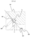
- FIG. 1 shows the overall configuration of a system for implementing the present invention.
- a portion surrounded by a broken line in FIG. 1 shows a pump housing 1 of a high-pressure fuel supply pump, and a mechanism and parts shown in the broken line are integrally incorporated therein.
- the fuel in the fuel tank 20 is pumped up by the feed pump 21 and sent to the fuel inlet 10 a of the pump housing 1 through the suction pipe 28.
- the fuel that has passed through the fuel intake port 10a reaches the intake port 30a of the electromagnetic intake valve mechanism 30 that constitutes the variable capacity mechanism via the pressure pulsation reducing mechanism 9 and the intake passage 10c.
- the electromagnetic suction valve mechanism 30 includes an electromagnetic coil 30b, and in a state where the electromagnetic coil 30b is energized, the electromagnetic plunger 30c compresses the spring 33 and moves to the right in FIG. Maintained. At this time, the suction valve body 31 attached to the tip of the electromagnetic plunger 30c opens the suction port 32 leading to the pressurizing chamber 11 of the high-pressure fuel supply pump.
- the electromagnetic coil 30 b is not energized and there is no fluid differential pressure between the suction passage 10 c (suction port 30 a) and the pressurizing chamber 11, the suction valve body 31 is moved by the biasing force of the spring 33.
- the suction port 32 is urged in the valve closing direction (leftward in FIG. 1) to be closed, and this state is maintained.
- the suction valve body 31 is moved leftward in FIG. 1 by the urging force of the spring 33 that is constantly acting on the suction valve body 31 to close the suction port 32.
- the suction port 32 is closed, the fuel pressure in the pressurizing chamber 11 rises with the rise of the plunger 2 from this time.
- the fuel pressure in the pressurizing chamber 11 exceeds a pressure larger than the fuel pressure in the discharge port 13 by a predetermined value, the fuel remaining in the pressurizing chamber 11 is discharged via the discharge valve mechanism 8. High pressure discharge is performed and supplied to the common rail 23. This process is called a discharge process.
- the compression process of the plunger 2 includes a return process and a discharge process.
- the pressure pulsation is generated in the suction passage due to the fuel returned to the suction passage 10c, but this pressure pulsation only slightly flows backward from the suction port 10a to the suction pipe 28, and the fuel is returned. Most of the energy is absorbed by the pressure pulsation reducing mechanism 9.
- the timing of releasing the energization of the electromagnetic coil 30c of the electromagnetic intake valve mechanism 30 the amount of high-pressure fuel discharged can be controlled. If the timing of releasing the energization to the electromagnetic coil 30b is advanced, the ratio of the return process in the compression process is reduced and the ratio of the discharge process is increased.
- the amount of fuel returned to the suction passage 10c is reduced and the amount of fuel discharged at high pressure is increased.
- the timing of releasing the energization is delayed, the ratio of the return process in the compression process is increased and the ratio of the discharge process is decreased. That is, more fuel is returned to the suction passage 10c and less fuel is discharged at high pressure.
- the timing of releasing the energization is controlled by a command from the ECU.
- the ECU controls the timing of releasing the energization of the electromagnetic coil, whereby the amount of fuel discharged at a high pressure can be made the amount required by the internal combustion engine.
- a discharge valve mechanism 8 is provided on the outlet side of the pressurizing chamber 11 between the discharge port (discharge side pipe connection portion) 13.
- the discharge valve mechanism 8 includes a sheet member 8a, a discharge valve 8b, a discharge valve spring 8c, and a holding member (discharge valve stopper) 8d.
- the discharge valve 8b In a state where there is no fuel differential pressure between the pressurizing chamber 11 and the discharge port 13, the discharge valve 8b is pressed against the seat member 8a by the urging force of the discharge valve spring 8c and is in a closed state.
- the discharge valve 8b After the discharge valve 8b is opened, the operation is restricted when it comes into contact with the holding member 8d. Therefore, the stroke of the discharge valve 8b is appropriately determined by the holding member 8d. If the stroke is too large, the fuel discharged to the fuel discharge port 13 flows back into the pressurizing chamber 11 again due to the delay in closing the discharge valve 8b, so that the efficiency of the high-pressure pump decreases. . Further, when the discharge valve 8b repeats opening and closing movements, the holding member 8d guides the discharge valve so as to move only in the stroke direction. By configuring as described above, the discharge valve mechanism 8 becomes a check valve that restricts the flow direction of fuel.
- the fuel introduced to the fuel suction port 10a is pressurized to a required amount by the reciprocating motion of the plunger 2 in the pressurizing chamber 11 of the pump body 1, and the fuel discharge port 13 passes through the discharge valve mechanism 8.
- the common rail 23 which is a high-pressure pipe.
- the common rail 23 is provided with an injector 24 and a pressure sensor 26.
- the injectors 24 are mounted in accordance with the number of cylinders of the internal combustion engine, and the fuel is injected into the cylinders by operating the on-off valve according to the control signal of the ECU 27.
- the pump housing 1 is provided with a relief passage 300 that connects the discharge passage 12 and the suction passage 10c.
- the relief passage 300 restricts the flow of fuel in only one direction from the discharge passage 12 to the suction passage 10c.
- a valve 200 is provided.
- the fuel flow in the relief passage 300 may flow from the discharge passage 12 into the pressurizing chamber 11.
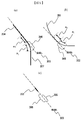
- FIG. 3 shows a cross section of the relief valve according to the first embodiment of the present invention.
- the relief valve 200 includes a valve body 201, an elastic member 203 that biases the valve body, a seat member 204 that engages with the valve body to seal fuel, a housing 205, a high-pressure chamber 206 on the upstream side of the valve body, and a downstream side of the valve body.
- the low-pressure chamber 207 is configured.
- the valve body 201 is urged against the sheet portion 204 by the elastic member 203 against the high pressure guided from the discharge flow path 12.
- a position where the valve body 201 and the sheet member 204 are in contact with each other is defined as a seat position 202.
- the seat position 202 In the cross section in the vicinity of the seat position 202, when the valve body 201 and the sheet member 204 are parallel straight lines, the seat position 202 has a width, and the valve body 201 and the sheet member 204 are in surface contact.
- the valve body 201 In the cross section in the vicinity of the seat position 202, when the valve body 201 is a curve and the seat member 204 is a straight line, they contact at one point from a geometrical point of view.
- the seat position 202 has a certain width, and even in this case, it can be said that the valve body 201 and the seat member 204 are in surface contact.
- a high-pressure passage 207 leading to the high-pressure chamber 206 is provided on the upstream side of the seat position 202, and the diameter of the high-pressure passage 207 is defined as a high-pressure passage diameter 208. If the high-pressure passage diameter 208 is small, the high-pressure passage 207 becomes narrow, and it becomes difficult for the fuel to flow when the relief valve is opened. In order to allow sufficient fuel to flow when the relief valve is opened, that is, to obtain good flow characteristics, it is desirable to increase the high-pressure passage diameter 208.
- FIG. 4 is an enlarged view of the shape in the vicinity of the sheet position 202 in the cross-sectional view of FIG.
- the valve body 201 and the seat member 204 are in contact with each other at the seat position 202, and have a common tangent L303 on the cross section shown in FIG. Further, the valve body 201 is provided with a curvature radius Rv in the vicinity of the seat position 202, and similarly, the seat member 204 is provided with a curvature radius Rs in the vicinity of the seat position 202.
- the curvature radius Rv and the curvature radius Rs are in contact with each other at the seat position 202, and not only the vicinity of the seat position 202 but also the same curvature radius may continue upstream and downstream of the seat position 202.
- the curvature radius Rs and the curvature radius Rv can be set to arbitrary values, and the curvature radius may be infinite, that is, arranged as a straight line.
- FIG. 5A shows a schematic view of the shape of the sheet member 204
- FIG. 5B shows a schematic view of the shape of the valve body 201.
- the curvature radius R2 smaller than the curvature radius Rs of the sheet
- a section obtained by projecting the section having the radius of curvature R2 perpendicularly to the tangent L303 is defined as a projection section 306.
- the valve body 201 is provided with a curvature radius R1 smaller than the curvature radius Rv in the vicinity of the seat position 202 at least at one location upstream of the seat position 202.
- a section obtained by vertically projecting the section having the curvature radius R1 onto the tangent line L303 is defined as a projection section 305.
- FIG. 5C schematically shows the positional relationship between the projection sections.
- the curvature radius R1 and the curvature radius R2 are arranged upstream of the sheet position 202 so that the projection section 306 and the projection section 305 overlap at least partially on the tangent L303.
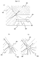
- FIG. 6 (a) shows a comparison between the prior art and the present invention.
- the cross-sectional shape of the sheet member in the prior art is indicated by 402, and the cross-sectional shape of the valve body is indicated by 401.
- the sheet member 204 is provided with a radius of curvature R2 from Rv to the high-pressure passage 207, so that the high-pressure passage diameter 208 is larger than that of the conventional sheet member shape 402. Can do.
- FIG. 6B schematically shows the fuel flow direction 404 when the valve body 201 is not provided with R1.
- R1 is not provided on the valve body side
- the flow of fuel 404 is uneven between the flow along the seat member and the flow along the valve body, and when high-speed fuel passes, the flow direction of the fuel changes abruptly. End up.
- FIG. 6C schematically shows the fuel flow direction 405 when the valve body 201 is provided with R1.
- the curvature radius R1 and the curvature radius R2 are set to be close values, and the projection section 306 and the projection section 305 are arranged so as to largely overlap, so that the flow along the valve body and the flow along the seat member are It becomes more even and prevents the flow direction from changing suddenly. Therefore, separation of fluid and vortex are less likely to occur, and a great effect can be obtained by suppressing the occurrence of cavitation.
- FIG. 7 shows a cross-sectional shape of the sheet member 204 in the second embodiment of the present invention.
- a curvature radius Rs is provided in the vicinity of the seat position 202 in contact with the valve body 201.
- the radius of curvature Rs is infinite, that is, arranged as a straight line.
- an edge 501 is formed upstream of the polished surface. If the curvature radius R2 is arranged further upstream of the edge 501, the flow direction of the fuel does not change suddenly even when the fuel passes through the vicinity of the edge 501, and the occurrence of cavitation can be suppressed and erosion can be avoided. it can.
- FIG. 8A shows a cross-sectional shape of the valve body 201 according to the second embodiment of the present invention.
- a radius of curvature R0 is provided in the vicinity of the sheet position 202 in contact with the sheet member 201.
- the definition of the radius of curvature R0 is shown in FIG.
- the curvature radius R ⁇ b> 0 is a radius of a sphere that is in contact with the same position as the seat position 202 in contact with the valve body 201 in the seat member 204.
- the radius of curvature of the ball when the ball is used as the valve body in the prior art is R0.
- the curvature radius R0 is set as the curvature radius in the vicinity of the seat position 202, and a curvature radius R1 smaller than the curvature radius R0 is provided on the upstream side of the curvature radius R0.
- FIG. 9 shows the positional relationship between the projection section 305 and the projection section 306 on the tangent line L303 in the second embodiment.
- a curvature radius R2 is provided upstream of the sheet position 202, and a section obtained by projecting the section of the curvature radius R2 perpendicularly to the tangent L303 is defined as a projection section 306.
- the curvature radius R0 is set as the curvature radius in the vicinity of the seat position 202, and a curvature radius R1 smaller than the curvature radius R0 is provided on the upstream side of the curvature radius R0.
- 9C schematically shows the positional relationship between the projection sections.
- the curvature radius R1 and the curvature radius R2 are arranged upstream of the sheet position 202 so that the projection section 306 and the projection section 305 overlap at least partially on the tangent L303.
- the valve body 201 and the sheet member 204 come into contact with the spherical surface and the conical surface only in the vicinity of the seat position 202. Therefore, as long as the valve body 201 is in contact with the sheet member 204 within the range of the curvature radius R0, even when the valve body 201 is tilted, the sheet property can be maintained without generating a gap. If the section of the radius of curvature R0 is provided based on the maximum inclination angle allowed for the structure of the valve body 201, the sheet property can be maintained even when the valve body 201 is inclined most greatly.
- a curvature radius R1 smaller than the curvature radius R0 is provided upstream of the curvature radius R0, and the curvature radius R1 and the curvature radius R2 are arranged so that the projection section 306 and the projection section 305 at least partially overlap on the tangent L303.
Abstract
The purpose of the present invention is to provide a high-pressure fuel pump that achieves the avoidance of cavitation erosion and the improvement of flow rate characteristics at the same time.
A valve body has a curvature radius (Rv) at a seat portion that contacts a seat member and has a curvature radius (R1) upstream of the seat portion. The seat member has a curvature radius (Rs) at a seat portion that contacts the valve body and has a curvature radius (R2) upstream of the seat portion. The curvature radius (R1) is smaller than the curvature radius (Rv), and the curvature radius (R2) is smaller than the curvature radius (Rs). When the valve body and the seat member are in contact in a seated position via a tangent line (L) in a cross section, respective projected sections in which a curve section including the curvature radius (R1) and a curve section including the curvature radius (R2) are vertically projected to the tangent line (L) in the cross section are at least partially overlapped with each other.
Description
本発明は、高圧燃料ポンプにおいて、高圧側から低圧側へ高圧燃料をリリーフするリリーフ弁、および当該リリーフ弁を備える高圧燃料ポンプに関する。
The present invention relates to a relief valve that relieves high-pressure fuel from a high-pressure side to a low-pressure side in a high-pressure fuel pump, and a high-pressure fuel pump including the relief valve.
加圧燃料を内燃機関に燃料を供給する高圧燃料ポンプは、噴射器によって内燃機関の燃焼室内へ燃料が直接噴射される直接噴射運転に基づいた燃料供給系に使用することができる。この燃料供給系において、高圧燃料ポンプが故障したとき等に燃料圧力が許容値を超える高圧になり、配管やインジェクタ等が破損することを避けるため、燃料供給系統にリリーフ弁が設けられている。リリーフ弁は、高圧ポンプの加圧室で加圧された燃料を吐出する吐出弁よりも下流側の高圧側燃料通路と、低圧側の燃料通路と接続される。高圧側燃料通路の圧力が、設定された所定圧よりも高くなるときにリリーフ弁は開弁し、高圧側燃料通路の燃料圧力を下げる機能を持っている(例えば特許文献1参照)。
The high-pressure fuel pump that supplies the pressurized fuel to the internal combustion engine can be used in a fuel supply system based on a direct injection operation in which the fuel is directly injected into the combustion chamber of the internal combustion engine by an injector. In this fuel supply system, a relief valve is provided in the fuel supply system in order to prevent the fuel pressure from exceeding a permissible value when the high-pressure fuel pump fails or the like, and damage to the piping and injectors. The relief valve is connected to the high-pressure side fuel passage downstream of the discharge valve that discharges fuel pressurized in the pressurizing chamber of the high-pressure pump, and the low-pressure side fuel passage. When the pressure in the high-pressure side fuel passage becomes higher than a predetermined pressure, the relief valve opens and has a function of reducing the fuel pressure in the high-pressure side fuel passage (see, for example, Patent Document 1).
これまでの従来技術には次のような課題があった。
The conventional technology has the following problems.
高圧燃料ポンプのリリーフ弁は、吐出圧が許容値を超えて高くなる異常圧の発生を抑制する機能がある。よって吐出圧が設定圧力を超えて高くなった場合、リリーフ弁の弁体が開弁し、リリーフ弁から低圧側に燃料が流れることで高い圧力を下げることができる。吐出圧が許容値以下であるときは、弁体はシート部に着座して、燃料を完全にシールする必要がある。リリーフ弁の弁体が開弁し、高圧側から低圧側へ燃料が流れる際には、シート部材と弁体によって形成される流路を燃料が高速で流れる。このとき、シート部材もしくは弁体にエッジがあると、高速な燃料の流れがエッジ付近を通過する際に流体の流れ方向が急変することで剥離を起こし、キャビテーション気泡が発生することがある。キャビテーション気泡がシート部近傍で崩壊すると、シート部にエロージョンを起こし、最悪の場合はシール性能に支障をきたすことがある。
The relief valve of the high-pressure fuel pump has a function to suppress the occurrence of abnormal pressure where the discharge pressure becomes higher than the allowable value. Therefore, when the discharge pressure becomes higher than the set pressure, the valve body of the relief valve opens, and the high pressure can be lowered by fuel flowing from the relief valve to the low pressure side. When the discharge pressure is less than the allowable value, the valve body needs to be seated on the seat portion to completely seal the fuel. When the valve body of the relief valve opens and the fuel flows from the high pressure side to the low pressure side, the fuel flows at high speed through the flow path formed by the seat member and the valve body. At this time, if there is an edge in the seat member or the valve body, when the high-speed fuel flow passes in the vicinity of the edge, the fluid flow direction changes suddenly to cause separation, and cavitation bubbles may be generated. When the cavitation bubbles collapse in the vicinity of the seat portion, erosion occurs in the seat portion, and in the worst case, the sealing performance may be hindered.
このキャビテーションエロージョンを回避するため、高速な燃料が通過するエッジ部の曲率半径を大きく取ることで、剥離を抑えることができる。例えば特許文献1に記載のように、シート部上流のエッジ部に大きい曲率半径を施すことで、流れ方向が急に変化することを回避することができる。しかし、エッジ部に大きい曲率半径を配置することでリリーフ弁の高圧側の通路を狭くしてしまう。高圧側の通路が狭くなってしまうとリリーフ弁の流量特性が悪化し、リリーフ弁が開弁しても十分な流量を流せなくなってしまうことから、圧力を下げる効果が十分に得られなくなってしまう場合があった。
In order to avoid this cavitation erosion, peeling can be suppressed by taking a large radius of curvature at the edge where high-speed fuel passes. For example, as described in Patent Document 1, it is possible to avoid a sudden change in the flow direction by applying a large radius of curvature to the edge portion upstream of the seat portion. However, disposing a large radius of curvature at the edge portion narrows the passage on the high pressure side of the relief valve. If the passage on the high-pressure side becomes narrow, the flow rate characteristics of the relief valve will deteriorate, and even if the relief valve opens, it will not be possible to flow a sufficient flow rate, so the effect of reducing the pressure will not be sufficiently obtained There was a case.
このように、キャビテーションの発生抑制と流量特性の確保はトレードオフの関係にあり、従来技術では両立が難しかった。本発明は上記事情に基づいて成されたもので、その目的はキャビテーションの発生抑制と流量特性の改善を両立する高圧燃料ポンプを提供することである。
Thus, the suppression of cavitation generation and the securing of flow characteristics are in a trade-off relationship, and it was difficult to achieve both with the conventional technology. The present invention has been made based on the above circumstances, and an object of the present invention is to provide a high-pressure fuel pump that achieves both suppression of cavitation generation and improvement of flow characteristics.
上記目的は、その一例として、弁体とシート部の曲率を適切な値とすることで達成できる。
The above object can be achieved, for example, by setting the curvature of the valve body and the seat part to appropriate values.
本発明によれば、キャビテーションエロージョンの回避と流量特性の改善を両立することができる。
According to the present invention, it is possible to achieve both avoidance of cavitation erosion and improvement of flow characteristics.
以下、図を参照して、本発明の実施例を説明する。
図1は、本発明を実施するシステムの全体構成を示す。図1において破線で囲まれた部分は、高圧燃料供給ポンプのポンプハウジング1を示し、この破線の中に示された機構と部品を、その中に一体に組み込んでいる。 Hereinafter, embodiments of the present invention will be described with reference to the drawings.
FIG. 1 shows the overall configuration of a system for implementing the present invention. A portion surrounded by a broken line in FIG. 1 shows a pump housing 1 of a high-pressure fuel supply pump, and a mechanism and parts shown in the broken line are integrally incorporated therein.
燃料タンク20中の燃料は、フィードポンプ21によって汲み上げられ、吸入配管28を通じてポンプハウジング1の燃料吸入口10aに送られる。燃料吸入口10aを通過した燃料は、圧力脈動低減機構9、吸入通路10cを介して、容量可変機構を構成する電磁吸入弁機構30の吸入ポート30aに至る。
The fuel in the fuel tank 20 is pumped up by the feed pump 21 and sent to the fuel inlet 10 a of the pump housing 1 through the suction pipe 28. The fuel that has passed through the fuel intake port 10a reaches the intake port 30a of the electromagnetic intake valve mechanism 30 that constitutes the variable capacity mechanism via the pressure pulsation reducing mechanism 9 and the intake passage 10c.
電磁吸入弁機構30は、電磁コイル30bを備え、この電磁コイル30bが通電されている状態で、電磁プランジャ30cは、ばね33を圧縮して図1における右方に移動した状態となり、その状態が維持される。このとき電磁プランジャ30cの先端に取付けられた吸入弁体31は、高圧燃料供給ポンプの加圧室11に通じる吸入口32を開く。電磁コイル30bが通電されていない状態であって、吸入通路10c(吸入ポート30a)と加圧室11との間に流体差圧がない時は、ばね33の付勢力により、吸入弁体31は、閉弁方向(図1における左方)に付勢されて吸入口32は閉じられた状態となって、この状態が維持される。
The electromagnetic suction valve mechanism 30 includes an electromagnetic coil 30b, and in a state where the electromagnetic coil 30b is energized, the electromagnetic plunger 30c compresses the spring 33 and moves to the right in FIG. Maintained. At this time, the suction valve body 31 attached to the tip of the electromagnetic plunger 30c opens the suction port 32 leading to the pressurizing chamber 11 of the high-pressure fuel supply pump. When the electromagnetic coil 30 b is not energized and there is no fluid differential pressure between the suction passage 10 c (suction port 30 a) and the pressurizing chamber 11, the suction valve body 31 is moved by the biasing force of the spring 33. The suction port 32 is urged in the valve closing direction (leftward in FIG. 1) to be closed, and this state is maintained.
後述する内燃機関のカムの回転により、プランジャ2が図1の下方に変位して吸入工程状態にある時は、加圧室11の容積は増加し、その中の燃料圧力は低下する。この工程において、加圧室11内の燃料圧力が吸入通路10c(吸入ポート30a)の圧力よりも低くなると、吸入弁体31には燃料の流体差圧による開弁力(吸入弁体31を図1の右方に変位させる力)が発生する。この開弁力により、吸入弁体31は、ばね33の付勢力に打ち勝って開弁し、吸入口32を開く。この状態にて、ECU27からの制御信号が電磁吸入弁機構30に印加されると電磁吸入弁30の電磁コイル30bに電流が流れ、磁気付勢力により電磁プランジャ30cがばね33を更に圧縮して、図1の右方に移動して、吸入口32を開いた状態を維持する。
When the plunger 2 is displaced downward in FIG. 1 due to the rotation of the cam of the internal combustion engine, which will be described later, and the suction chamber 11 is in the suction process state, the volume of the pressurizing chamber 11 increases and the fuel pressure therein decreases. In this step, when the fuel pressure in the pressurizing chamber 11 becomes lower than the pressure in the suction passage 10c (suction port 30a), the suction valve body 31 has a valve opening force (suction valve body 31 shown in FIG. 1) is generated. By this valve opening force, the suction valve body 31 overcomes the urging force of the spring 33 and opens to open the suction port 32. In this state, when a control signal from the ECU 27 is applied to the electromagnetic intake valve mechanism 30, an electric current flows through the electromagnetic coil 30b of the electromagnetic intake valve 30, and the electromagnetic plunger 30c further compresses the spring 33 by the magnetic biasing force. It moves to the right in FIG. 1 and maintains the state where the inlet 32 is open.
電磁吸入弁機構30に入力電圧の印加状態を維持したまま、プランジャ2が吸入工程から圧縮工程(下始点から上始点までの間の上昇工程)へと移行すると、電磁コイル30bへの通電状態が維持されているので、磁気付勢力は維持されて吸入弁体31は依然として開弁した状態を維持する。加圧室11の容積は、プランジャ2の圧縮運動に伴って減少するが、この状態では、一度加圧室11に吸入された燃料が、再び開弁状態の吸入弁体31と吸入口32との間を通過して吸入通路10c(吸入ポート30a)へと戻されるので、加圧室11の圧力が上昇することはない。この工程を、戻し工程という。
When the plunger 2 shifts from the suction process to the compression process (the ascending process from the lower start point to the upper start point) while maintaining the application state of the input voltage to the electromagnetic intake valve mechanism 30, the energized state of the electromagnetic coil 30b is changed. Since it is maintained, the magnetic urging force is maintained, and the suction valve body 31 still maintains the opened state. The volume of the pressurizing chamber 11 decreases with the compression movement of the plunger 2. In this state, the fuel once sucked into the pressurizing chamber 11 is once again opened into the intake valve body 31 and the inlet 32. Between the pressure chamber 11 and the suction passage 10c (suction port 30a), the pressure in the pressurizing chamber 11 does not increase. This process is called a return process.
戻し工程において、電磁コイル30bへの通電を断つと、電磁プランジャ30cに働いていた磁気付勢力は一定時間後(磁気的、機械的遅れ時間後)に消去される。そうすると、吸入弁体31に常時働いているばね33の付勢力により、吸入弁体31は図1において左方に移動されて吸入口32を閉じる。吸入口32が閉じると、この時から加圧室11内の燃料圧力は、プランジャ2の上昇と共に上昇する。そして、加圧室11内の燃料圧力が、吐出口13の燃料圧力よりも所定の値だけ大きい圧力を超えた時に、加圧室11に残っている燃料は、吐出弁機構8を介して、高圧吐出が行われてコモンレール23へと供給される。この工程を吐出工程という。上記のとおり、プランジャ2の圧縮工程は、戻し工程と吐出工程からなる。
In the returning step, when the energization to the electromagnetic coil 30b is cut off, the magnetic urging force acting on the electromagnetic plunger 30c is erased after a certain time (after the magnetic and mechanical delay time). Then, the suction valve body 31 is moved leftward in FIG. 1 by the urging force of the spring 33 that is constantly acting on the suction valve body 31 to close the suction port 32. When the suction port 32 is closed, the fuel pressure in the pressurizing chamber 11 rises with the rise of the plunger 2 from this time. When the fuel pressure in the pressurizing chamber 11 exceeds a pressure larger than the fuel pressure in the discharge port 13 by a predetermined value, the fuel remaining in the pressurizing chamber 11 is discharged via the discharge valve mechanism 8. High pressure discharge is performed and supplied to the common rail 23. This process is called a discharge process. As described above, the compression process of the plunger 2 includes a return process and a discharge process.
戻し工程中に、吸入通路10cへ戻された燃料により吸入通路には圧力脈動が発生するが、この圧力脈動は、吸入口10aから吸入配管28へ僅かに逆流するのみであり、燃料の戻しの大部分は圧力脈動低減機構9により吸収される。電磁吸入弁機構30の電磁コイル30cへの通電解除のタイミングを制御することにより、吐出される高圧燃料の量を制御することができる。電磁コイル30bへの通電解除のタイミングを早くすれば、圧縮工程における戻し工程の割合を小さく、吐出工程の割合を大きくする。すなわち、吸入通路10c(吸入ポート30a)に戻される燃料を少なく、高圧吐出される燃料を多くする。これに対し、上記の通電解除のタイミングを遅くすれば、圧縮工程における戻し工程の割合を大きく、吐出工程の割合を小さくする。すなわち、吸入通路10cに戻される燃料を多く、高圧吐出される燃料を少なくする。上記の通電解除のタイミングは、ECUから指令により制御される。
During the returning process, the pressure pulsation is generated in the suction passage due to the fuel returned to the suction passage 10c, but this pressure pulsation only slightly flows backward from the suction port 10a to the suction pipe 28, and the fuel is returned. Most of the energy is absorbed by the pressure pulsation reducing mechanism 9. By controlling the timing of releasing the energization of the electromagnetic coil 30c of the electromagnetic intake valve mechanism 30, the amount of high-pressure fuel discharged can be controlled. If the timing of releasing the energization to the electromagnetic coil 30b is advanced, the ratio of the return process in the compression process is reduced and the ratio of the discharge process is increased. That is, the amount of fuel returned to the suction passage 10c (suction port 30a) is reduced and the amount of fuel discharged at high pressure is increased. On the other hand, if the timing of releasing the energization is delayed, the ratio of the return process in the compression process is increased and the ratio of the discharge process is decreased. That is, more fuel is returned to the suction passage 10c and less fuel is discharged at high pressure. The timing of releasing the energization is controlled by a command from the ECU.
以上のように、ECUが電磁コイルの通電解除のタイミングを制御することにより、高圧吐出される燃料量を、内燃機関が必要とする量とすることができる。
As described above, the ECU controls the timing of releasing the energization of the electromagnetic coil, whereby the amount of fuel discharged at a high pressure can be made the amount required by the internal combustion engine.
ポンプハウジング1内において、加圧室11の出口側には吐出口(吐出側配管接続部)13との間に吐出弁機構8が設けられる。吐出弁機構8は、シート部材8a、吐出弁8b、吐出弁ばね8c、保持部材(吐出弁ストッパー)8dからなる。加圧室11と吐出口13との間に燃料の差圧がない状態では、吐出弁8bは、吐出弁ばね8cによる付勢力でシート部材8aに圧着され閉弁状態となっている。加圧室11内の燃料圧力が、吐出口13の燃料圧力よりも所定の値だけ大きい圧力を超えた時に、吐出弁8bは吐出弁ばね8cに抗して開弁し、加圧室11内の燃料は吐出口13を経てコモンレール23へと吐出される。
In the pump housing 1, a discharge valve mechanism 8 is provided on the outlet side of the pressurizing chamber 11 between the discharge port (discharge side pipe connection portion) 13. The discharge valve mechanism 8 includes a sheet member 8a, a discharge valve 8b, a discharge valve spring 8c, and a holding member (discharge valve stopper) 8d. In a state where there is no fuel differential pressure between the pressurizing chamber 11 and the discharge port 13, the discharge valve 8b is pressed against the seat member 8a by the urging force of the discharge valve spring 8c and is in a closed state. When the fuel pressure in the pressurizing chamber 11 exceeds a pressure larger than the fuel pressure in the discharge port 13 by a predetermined value, the discharge valve 8b opens against the discharge valve spring 8c, and the pressure chamber 11 opens. The fuel is discharged to the common rail 23 through the discharge port 13.
吐出弁8bは開弁した後、保持部材8dと接触すると動作を制限される。そのゆえ、吐出弁8bのストロークは、保持部材8dによって適切に決定される。もし、ストロークが大きすぎると、吐出弁8bの閉じ遅れにより、燃料吐出口13へ吐出される燃料が、再び加圧室11内に逆流してしまうので、高圧ポンプとしての効率が低下してしまう。また、吐出弁8bが開弁と閉弁運動を繰り返す時に、吐出弁がストローク方向にのみ運動するように、保持部材8dによりガイドしている。以上のように構成することにより、吐出弁機構8は、燃料の流通方向を制限する逆止弁となる。
After the discharge valve 8b is opened, the operation is restricted when it comes into contact with the holding member 8d. Therefore, the stroke of the discharge valve 8b is appropriately determined by the holding member 8d. If the stroke is too large, the fuel discharged to the fuel discharge port 13 flows back into the pressurizing chamber 11 again due to the delay in closing the discharge valve 8b, so that the efficiency of the high-pressure pump decreases. . Further, when the discharge valve 8b repeats opening and closing movements, the holding member 8d guides the discharge valve so as to move only in the stroke direction. By configuring as described above, the discharge valve mechanism 8 becomes a check valve that restricts the flow direction of fuel.
こうして、燃料吸入口10aに導かれた燃料は、ポンプ本体1の加圧室11内にてプランジャ2の往復動によって必要な量が高圧に加圧され、吐出弁機構8を通じて、燃料吐出口13から高圧配管であるコモンレール23に圧送される。
Thus, the fuel introduced to the fuel suction port 10a is pressurized to a required amount by the reciprocating motion of the plunger 2 in the pressurizing chamber 11 of the pump body 1, and the fuel discharge port 13 passes through the discharge valve mechanism 8. To the common rail 23, which is a high-pressure pipe.
コモンレール23には、インジェクタ24と圧力センサ26が装着されている。インジェクタ24は、内燃機関の気筒数に合わせて装着されており、ECU27の制御信号により、開閉弁の動作をして、燃料をシリンダ内に噴射する。
The common rail 23 is provided with an injector 24 and a pressure sensor 26. The injectors 24 are mounted in accordance with the number of cylinders of the internal combustion engine, and the fuel is injected into the cylinders by operating the on-off valve according to the control signal of the ECU 27.
次に、インジェクタ24の故障等によりコモンレール23等の高圧部に異常高圧が発生した場合の、実施例における燃料リリーフ動作について説明する。
Next, the fuel relief operation in the embodiment when an abnormal high pressure occurs in the high pressure portion such as the common rail 23 due to a failure of the injector 24 or the like will be described.
ポンプハウジング1には、吐出通路12と吸入通路10cを連通するリリーフ通路300が設けられており、リリーフ通路300には燃料の流れを吐出通路12から吸入通路10cへの一方向のみに制限するリリーフ弁200が設けられている。
The pump housing 1 is provided with a relief passage 300 that connects the discharge passage 12 and the suction passage 10c. The relief passage 300 restricts the flow of fuel in only one direction from the discharge passage 12 to the suction passage 10c. A valve 200 is provided.
また図2に示すように、リリーフ通路300の燃料の流れが吐出通路12から加圧室11内となる場合もある。
In addition, as shown in FIG. 2, the fuel flow in the relief passage 300 may flow from the discharge passage 12 into the pressurizing chamber 11.
図3は、本発明の実施例1に係わるリリーフ弁の断面を示す。リリーフ弁200は、弁体201、弁体を付勢する弾性部材203、弁体と係合して燃料をシールするシート部材204、ハウジング205、弁体上流側の高圧室206、弁体下流側の低圧室207で構成されている。弁体201は、吐出流路12から導かれる高圧に対抗して、弾性部材203により、シート部204に付勢されている。
FIG. 3 shows a cross section of the relief valve according to the first embodiment of the present invention. The relief valve 200 includes a valve body 201, an elastic member 203 that biases the valve body, a seat member 204 that engages with the valve body to seal fuel, a housing 205, a high-pressure chamber 206 on the upstream side of the valve body, and a downstream side of the valve body. The low-pressure chamber 207 is configured. The valve body 201 is urged against the sheet portion 204 by the elastic member 203 against the high pressure guided from the discharge flow path 12.
吐出流路が高圧となり、高圧室206の圧力が上昇して所定の圧力より大きくなると、これにより弁体に作用する流体力が弾性部材203の付勢力を上回り、弁体201はシート部204を離れて上昇し、リリーフ通路は連通状態になる。この時高圧室206側が上流となり、低圧室206側へ燃料が流れる。また、再び、高圧室206の圧力が低下すると、弁体に作用する流体力よりも弾性部材203の付勢力が上回り、弁体201は下降して、シート部204に付着する。
When the discharge flow path becomes high pressure and the pressure in the high pressure chamber 206 rises and exceeds a predetermined pressure, the fluid force acting on the valve body exceeds the urging force of the elastic member 203, and the valve body 201 moves the seat portion 204. Ascending away, the relief passage is in communication. At this time, the high pressure chamber 206 side becomes upstream, and the fuel flows to the low pressure chamber 206 side. Further, when the pressure in the high pressure chamber 206 decreases again, the urging force of the elastic member 203 exceeds the fluid force acting on the valve body, and the valve body 201 descends and adheres to the seat portion 204.
弁体201とシート部材204が接触する箇所をシート位置202とする。シート位置202近傍の断面において、弁体201とシート部材204が平行な直線の場合は、シート位置202は幅をもっており、弁体201とシート部材204は面接触している。シート位置202近傍の断面において、弁体201が曲線、シート部材204が直線の場合は、幾何学的な観点では1点で接している。しかし実際の製品においては、各部材の表面粗さや摩耗を考慮すると、シート位置202では一定の幅をもっており、この場合でも弁体201とシート部材204は面接触していることが言える。
A position where the valve body 201 and the sheet member 204 are in contact with each other is defined as a seat position 202. In the cross section in the vicinity of the seat position 202, when the valve body 201 and the sheet member 204 are parallel straight lines, the seat position 202 has a width, and the valve body 201 and the sheet member 204 are in surface contact. In the cross section in the vicinity of the seat position 202, when the valve body 201 is a curve and the seat member 204 is a straight line, they contact at one point from a geometrical point of view. However, in the actual product, considering the surface roughness and wear of each member, the seat position 202 has a certain width, and even in this case, it can be said that the valve body 201 and the seat member 204 are in surface contact.
シート位置202の上流側には高圧室206へ通じる高圧通路207を有し、その高圧通路207の径を高圧通路径208とする。この高圧通路径208が小さいと高圧通路207が狭くなり、リリーフ弁が開弁した時に燃料が流れにくくなる。リリーフ弁開弁時に十分な燃料を流す、つまり良い流量特性を得るためには、高圧通路径208を大きくすることが望ましい。
A high-pressure passage 207 leading to the high-pressure chamber 206 is provided on the upstream side of the seat position 202, and the diameter of the high-pressure passage 207 is defined as a high-pressure passage diameter 208. If the high-pressure passage diameter 208 is small, the high-pressure passage 207 becomes narrow, and it becomes difficult for the fuel to flow when the relief valve is opened. In order to allow sufficient fuel to flow when the relief valve is opened, that is, to obtain good flow characteristics, it is desirable to increase the high-pressure passage diameter 208.
次に図4を用いて、本発明の実施例1においてのシート位置202近傍の形状について説明する。図4は図3の断面図において、シート位置202近傍の形状を拡大した図である。弁体201とシート部材204はシート位置202で接しており、図4に示す断面上で共通な接線L303をもつ。また、弁体201はシート位置202近傍にて曲率半径Rvを設けており、同様にシート部材204はシート位置202近傍において曲率半径Rsを設ける構成にする。曲率半径Rvと曲率半径Rsとはシート位置202で接しており、いずれの曲率半径もシート位置202の近傍だけではなく、シート位置202の上流、下流に同じ曲率半径が続いている構成でも良い。曲率半径Rs、曲率半径Rvは任意の値を設定することができ、曲率半径が無限大、すなわち直線として配置しても良い。
Next, the shape near the sheet position 202 in Embodiment 1 of the present invention will be described with reference to FIG. FIG. 4 is an enlarged view of the shape in the vicinity of the sheet position 202 in the cross-sectional view of FIG. The valve body 201 and the seat member 204 are in contact with each other at the seat position 202, and have a common tangent L303 on the cross section shown in FIG. Further, the valve body 201 is provided with a curvature radius Rv in the vicinity of the seat position 202, and similarly, the seat member 204 is provided with a curvature radius Rs in the vicinity of the seat position 202. The curvature radius Rv and the curvature radius Rs are in contact with each other at the seat position 202, and not only the vicinity of the seat position 202 but also the same curvature radius may continue upstream and downstream of the seat position 202. The curvature radius Rs and the curvature radius Rv can be set to arbitrary values, and the curvature radius may be infinite, that is, arranged as a straight line.
次に図5を用いて、本発明の実施例1においてのシート位置202上流の形状について説明する。図5の(a)にはシート部材204の形状を、(b)は弁体201の形状の模式図を示している。(a)に示すように、シート部材204ではシート位置202の上流に少なくとも1箇所、高圧通路207に至るまでの間に、シート位置202近傍の曲率半径Rsより小さい曲率半径R2を設ける。この曲率半径R2の区間を接線L303へ垂直に投影した区間を投影区間306とする。(b)に示すように、弁体201では同様に、シート位置202の上流に少なくとも1箇所、シート位置202近傍の曲率半径Rvより小さい曲率半径R1を設ける。この曲率半径R1の区間を接線L303へ垂直に投影した区間を投影区間305とする。図5の(c)にこの投影区間の位置関係を模式的にしめす。シート位置202の上流において、接線L303上で前記投影区間306と前記投影区間305が、少なくとも一部重なるように、曲率半径R1と曲率半径R2を配置する。
Next, the shape upstream of the sheet position 202 in the first embodiment of the present invention will be described with reference to FIG. FIG. 5A shows a schematic view of the shape of the sheet member 204, and FIG. 5B shows a schematic view of the shape of the valve body 201. As shown to (a), in the sheet | seat member 204, the curvature radius R2 smaller than the curvature radius Rs of the sheet | seat position 202 vicinity is provided in at least one location upstream from the sheet | seat position 202 until it reaches the high voltage | pressure channel | path 207. A section obtained by projecting the section having the radius of curvature R2 perpendicularly to the tangent L303 is defined as a projection section 306. As shown in (b), similarly, the valve body 201 is provided with a curvature radius R1 smaller than the curvature radius Rv in the vicinity of the seat position 202 at least at one location upstream of the seat position 202. A section obtained by vertically projecting the section having the curvature radius R1 onto the tangent line L303 is defined as a projection section 305. FIG. 5C schematically shows the positional relationship between the projection sections. The curvature radius R1 and the curvature radius R2 are arranged upstream of the sheet position 202 so that the projection section 306 and the projection section 305 overlap at least partially on the tangent L303.
図6の(a)に従来技術と本発明の比較を示す。従来技術のおけるシート部材の断面形状を402、弁体の断面形状を401に示す。図6の(a)に示す通り、シート部材204に曲率半径R2を、Rvから高圧通路207に至るまでの間に設けることで、従来シート部材形状402よりも、高圧通路径208を大きくとることができる。高圧通路径208を大きくすることで高圧通路207の流路面積が大きくなり、リリーフ弁の開弁時に十分な量の燃料を逃がすことができ、良い流量特性を得ることができる。
FIG. 6 (a) shows a comparison between the prior art and the present invention. The cross-sectional shape of the sheet member in the prior art is indicated by 402, and the cross-sectional shape of the valve body is indicated by 401. As shown in FIG. 6A, the sheet member 204 is provided with a radius of curvature R2 from Rv to the high-pressure passage 207, so that the high-pressure passage diameter 208 is larger than that of the conventional sheet member shape 402. Can do. By increasing the high-pressure passage diameter 208, the flow passage area of the high-pressure passage 207 is increased, a sufficient amount of fuel can be released when the relief valve is opened, and good flow characteristics can be obtained.
そして、弁体201にR1を設け、望ましくは曲率半径R1と曲率半径R2を近い値に設定し、投影区間306と投影区間305が重なるように配置することで、燃料の流れ方向が急に変化することを防ぐことができる。図6の(b)に、弁体201にR1を設けなかった場合の燃料の流れ方向404を模式的に示す。弁体側にR1を設けなかった場合、燃料の流れ404はシート部材に沿う流れと弁体に沿う流れが不均等になり、高速な燃料が通過した際には燃料の流れ方向が急に変化してしまう。図6の(c)に、弁体201にR1を設けた場合の燃料の流れ方向405を模式的に示す。弁体201にR1を設け、投影区間306と投影区間305が重なるように配置することで、図6の(c)に示すように、弁体に沿う流れとシート部材に沿う流れが均等になり、高速な燃料が通過した際には燃料の流れ方向405が急に変化することを防ぐことができる。
Then, R1 is provided in the valve body 201, preferably the curvature radius R1 and the curvature radius R2 are set to close values, and the projection section 306 and the projection section 305 are arranged so as to overlap, so that the fuel flow direction changes suddenly. Can be prevented. FIG. 6B schematically shows the fuel flow direction 404 when the valve body 201 is not provided with R1. When R1 is not provided on the valve body side, the flow of fuel 404 is uneven between the flow along the seat member and the flow along the valve body, and when high-speed fuel passes, the flow direction of the fuel changes abruptly. End up. FIG. 6C schematically shows the fuel flow direction 405 when the valve body 201 is provided with R1. By providing R1 on the valve body 201 and arranging the projection section 306 and the projection section 305 so as to overlap each other, the flow along the valve body and the flow along the sheet member become uniform as shown in FIG. When the high-speed fuel passes, it is possible to prevent the fuel flow direction 405 from changing suddenly.
弁体201のシート位置上流にR1を設けても、R1とR2の位置が遠い、つまり投影区間306と投影区間305が重ならなければ、流体の流れは不均等になってしまう。R1とR2を、接触L303を挟んで向かい合わせに配置することで初めて弁体に沿う流れとシート部材に沿う流れが均等になる。R1とR2を、接触L303を挟んで向かい合わせに配置する、つまり投影区間306と投影区間305が重なるように配置することで、燃料の流れが均等になり、流れ方向が急変することを回避することができる。
Even if R1 is provided upstream of the seat position of the valve body 201, if the positions of R1 and R2 are far from each other, that is, if the projection section 306 and the projection section 305 do not overlap, the fluid flow becomes uneven. The flow along the valve body and the flow along the seat member are equalized for the first time by arranging R1 and R2 facing each other across the contact L303. By arranging R1 and R2 so as to face each other across the contact L303, that is, so that the projection section 306 and the projection section 305 overlap each other, it is possible to prevent the fuel flow from becoming uniform and the flow direction from changing suddenly. be able to.
燃料がシート部を通過する際に、流れが不均等で流れ方向が急に変化すると、弁体201やシート部材204の表面で流体の剥離や渦が発生しキャビテーションを引き起こす。本発明においては、望ましくは曲率半径R1と曲率半径R2を近い値に設定し投影区間306と投影区間305が大部分重なるように配置することで、弁体に沿う流れとシート部材に沿う流れがより均等になり、流れ方向が急に変化することを防ぐ。したがって、流体の剥離や渦がより発生しにくくなり、キャビテーションの発生抑制により大きな効果を得ることができる。
When the fuel passes through the seat portion, if the flow is uneven and the flow direction changes suddenly, fluid separation or vortex is generated on the surface of the valve body 201 or the seat member 204 to cause cavitation. In the present invention, preferably, the curvature radius R1 and the curvature radius R2 are set to be close values, and the projection section 306 and the projection section 305 are arranged so as to largely overlap, so that the flow along the valve body and the flow along the seat member are It becomes more even and prevents the flow direction from changing suddenly. Therefore, separation of fluid and vortex are less likely to occur, and a great effect can be obtained by suppressing the occurrence of cavitation.
以上のように、本発明においてはキャビテーションエロージョンの回避と流量特性の改善を両立することができる。
As described above, in the present invention, both avoidance of cavitation erosion and improvement of flow characteristics can be achieved.
図7に本発明の実施例2におけるシート部材204の断面形状を示す。実施例1同様に、弁体201と接触しているシート位置202の近傍において、曲率半径Rsを設ける。実施例2では曲率半径Rsを無限大、つまり直線として配置する。シート位置202近傍を直線にすることで、シート面は円すい面となる。シート面を円すい面にすることで、燃料シートに必要な表面粗さに仕上げる研磨工程が容易になる。
FIG. 7 shows a cross-sectional shape of the sheet member 204 in the second embodiment of the present invention. Similar to the first embodiment, a curvature radius Rs is provided in the vicinity of the seat position 202 in contact with the valve body 201. In the second embodiment, the radius of curvature Rs is infinite, that is, arranged as a straight line. By making the vicinity of the sheet position 202 a straight line, the sheet surface becomes a conical surface. By making the sheet surface conical, the polishing process for finishing the surface roughness necessary for the fuel sheet is facilitated.
シート面を円すい面として研磨した際に、研磨した面の上流にエッジ501ができる。エッジ501のさらに上流に曲率半径R2を配置すれば、エッジ501の付近を燃料が通過した際でも燃料の流れ方向が急に変化することがなく、キャビテーションの発生を抑制しエロージョンを回避することができる。
When the sheet surface is polished as a conical surface, an edge 501 is formed upstream of the polished surface. If the curvature radius R2 is arranged further upstream of the edge 501, the flow direction of the fuel does not change suddenly even when the fuel passes through the vicinity of the edge 501, and the occurrence of cavitation can be suppressed and erosion can be avoided. it can.
図8の(a)に本発明の実施例2における弁体201の断面形状を示す。本実施例ではシート部材201と接触しているシート位置202の近傍において、曲率半径R0を設ける。曲率半径R0の定義を図8の(b)に示す。曲率半径R0とは、シート部材204において、弁体201と接するシート位置202と同じ位置に接する球の半径である。つまり従来技術において弁体としてボールを用いた際のボールの曲率半径がR0である。本実施例では曲率半径R0をシート位置202近傍の曲率半径として設定し、曲率半径R0の上流側に曲率半径R0より小さい曲率半径R1を設ける。
FIG. 8A shows a cross-sectional shape of the valve body 201 according to the second embodiment of the present invention. In this embodiment, a radius of curvature R0 is provided in the vicinity of the sheet position 202 in contact with the sheet member 201. The definition of the radius of curvature R0 is shown in FIG. The curvature radius R <b> 0 is a radius of a sphere that is in contact with the same position as the seat position 202 in contact with the valve body 201 in the seat member 204. In other words, the radius of curvature of the ball when the ball is used as the valve body in the prior art is R0. In this embodiment, the curvature radius R0 is set as the curvature radius in the vicinity of the seat position 202, and a curvature radius R1 smaller than the curvature radius R0 is provided on the upstream side of the curvature radius R0.
図9に実施例2においての接線L303上における投影区間305と投影区間306の位置関係を示す。図9(a)に示すように、シート部材204ではシート位置202の上流に曲率半径R2を設け、この曲率半径R2の区間を接線L303へ垂直に投影した区間を投影区間306とする。また、図9(b)に示すように弁体201では曲率半径R0をシート位置202近傍の曲率半径として設定し、曲率半径R0の上流側に曲率半径R0より小さい曲率半径R1を設ける。図9(c)にこの投影区間の位置関係を模式的にしめす。シート位置202の上流において、接線L303上で前記投影区間306と前記投影区間305が、少なくとも一部重なるように、曲率半径R1と曲率半径R2を配置する。
FIG. 9 shows the positional relationship between the projection section 305 and the projection section 306 on the tangent line L303 in the second embodiment. As shown in FIG. 9A, in the sheet member 204, a curvature radius R2 is provided upstream of the sheet position 202, and a section obtained by projecting the section of the curvature radius R2 perpendicularly to the tangent L303 is defined as a projection section 306. Further, as shown in FIG. 9B, in the valve body 201, the curvature radius R0 is set as the curvature radius in the vicinity of the seat position 202, and a curvature radius R1 smaller than the curvature radius R0 is provided on the upstream side of the curvature radius R0. FIG. 9C schematically shows the positional relationship between the projection sections. The curvature radius R1 and the curvature radius R2 are arranged upstream of the sheet position 202 so that the projection section 306 and the projection section 305 overlap at least partially on the tangent L303.
弁体201のシート位置202近傍に曲率半径R0を設けることで、弁体201とシート部材204はシート位置202近傍でのみ、球面と円すい面との接触になる。したがって弁体201が曲率半径R0の範囲内でシート部材204と接触する限り、弁体201が傾いた時でも隙間が生じることなくシート性を保つことができる。曲率半径R0の区間を、弁体201の構造上許容される最大傾き角に基づいて設ければ、弁体201が最も大きく傾いた時でもシート性を保つことができる。
By providing the curvature radius R0 in the vicinity of the seat position 202 of the valve body 201, the valve body 201 and the sheet member 204 come into contact with the spherical surface and the conical surface only in the vicinity of the seat position 202. Therefore, as long as the valve body 201 is in contact with the sheet member 204 within the range of the curvature radius R0, even when the valve body 201 is tilted, the sheet property can be maintained without generating a gap. If the section of the radius of curvature R0 is provided based on the maximum inclination angle allowed for the structure of the valve body 201, the sheet property can be maintained even when the valve body 201 is inclined most greatly.
さらに曲率半径R0の上流側に曲率半径R0より小さい曲率半径R1を設け、接線L303上で前記投影区間306と前記投影区間305が、少なくとも一部重なるように、曲率半径R1と曲率半径R2を配置することで実施例1と同様に、キャビテーションエロージョンの回避と流量特性の改善を両立することができる。
Further, a curvature radius R1 smaller than the curvature radius R0 is provided upstream of the curvature radius R0, and the curvature radius R1 and the curvature radius R2 are arranged so that the projection section 306 and the projection section 305 at least partially overlap on the tangent L303. Thus, similarly to the first embodiment, it is possible to achieve both avoidance of cavitation erosion and improvement of flow rate characteristics.
当然ながら、実施例1での弁体形状と実施例2でのシート部材形状とを組み合わせ、または実施例2での弁体形状と実施例1でのシート部材形状とを組み合わせても同様の効果を得ることができる。
Naturally, the same effect can be obtained by combining the valve body shape in Example 1 and the sheet member shape in Example 2 or combining the valve body shape in Example 2 and the sheet member shape in Example 1. Can be obtained.
1…ポンプハウジング
2…プランジャ
8…吐出弁機構
9…圧力脈動低減機構
10c…吸入通路
11…加圧室
12…吐出通路
20…燃料タンク
23…コモンレール
24…インジェクタ
26…圧力センサ
30…電磁吸入弁機構
200…リリーフ弁
201…弁体
202…シート位置
203…弾性部材
204…シート部材
205…ハウジング
206…高圧室
207…低圧室
303…シート位置における共通接線
401…従来技術における弁体の断面形状
402…従来技術におけるシート部材の断面形状
501…円すい面の研磨によってできるエッジ DESCRIPTION OF SYMBOLS 1 ... Pump housing 2 ... Plunger 8 ...Discharge valve mechanism 9 ... Pressure pulsation reduction mechanism 10c ... Suction passage 11 ... Pressurization chamber 12 ... Discharge passage 20 ... Fuel tank 23 ... Common rail 24 ... Injector 26 ... Pressure sensor 30 ... Electromagnetic suction valve Mechanism 200 ... Relief valve 201 ... Valve body 202 ... Seat position 203 ... Elastic member 204 ... Seat member 205 ... Housing 206 ... High pressure chamber 207 ... Low pressure chamber 303 ... Common tangent 401 at the seat position ... Cross sectional shape 402 of the valve body in the prior art ... Cross-sectional shape 501 of conventional sheet member ... Edge formed by grinding of conical surface
2…プランジャ
8…吐出弁機構
9…圧力脈動低減機構
10c…吸入通路
11…加圧室
12…吐出通路
20…燃料タンク
23…コモンレール
24…インジェクタ
26…圧力センサ
30…電磁吸入弁機構
200…リリーフ弁
201…弁体
202…シート位置
203…弾性部材
204…シート部材
205…ハウジング
206…高圧室
207…低圧室
303…シート位置における共通接線
401…従来技術における弁体の断面形状
402…従来技術におけるシート部材の断面形状
501…円すい面の研磨によってできるエッジ DESCRIPTION OF SYMBOLS 1 ... Pump housing 2 ... Plunger 8 ...
Claims (5)
- 弁体と、シート部材と、前記弁体を付勢する弾性部材とを有する高圧燃料供給ポンプであって、
前記弁体は、前記シート部材と接するシート部においての曲率半径がRであり、
前記弁体は、該シート部の上流で曲率半径R1を有し、
前記シート部材は、前記弁体と接するシート部の上流で曲率半径R2を有し、
前記曲率半径R1、R2は共に、前記曲率半径Rより小さい高圧燃料供給ポンプ。 A high-pressure fuel supply pump having a valve body, a seat member, and an elastic member that biases the valve body,
The valve body has a radius of curvature R at a seat portion in contact with the seat member,
The valve body has a radius of curvature R1 upstream of the seat portion,
The seat member has a radius of curvature R2 upstream of the seat portion in contact with the valve body,
The curvature radii R1 and R2 are both high pressure fuel supply pumps smaller than the curvature radius R. - プランジャの往復動作によって容積が変化する加圧室と、前記加圧室に燃料を吸入する吸入流路と、前記加圧室から前記燃料を吐出する吐出流路と、前記吸入流路中に設けられた吸入弁と、前記吐出流路中に設けられた吐出弁と、前記吐出流路に設けられたリリーフ弁を有する高圧燃料供給ポンプであって、
前記リリーフ弁は弁体と、シート部材と、前記弁体を付勢する弾性部材とからなり、
前記弁体は、前記シート部材と接するシート部においての曲率半径がRvであり、
前記シート部材は、前記弁体と接するシート部においての曲率半径がRsでるリリーフ弁であって、
前記弁体は、該シート部の上流で曲率半径R1を有し、
前記シート部材は、該シート部の上流で曲率半径R2を有し、
前記曲率半径R1は、前記曲率半径Rvより小さく、
前記曲率半径R2は、前記曲率半径Rsより小さく、
前記シート位置で弁体とシート部材が接する時の、リリーフ弁中心軸を含む断面上での接線をLとした時、
前記接線Lに、前記R1を含む曲線区間と前記R2を含む曲線区間をそれぞれ垂直に投影したときに、両者が少なくとも一部重なり合うことを特徴とする高圧燃料ポンプ。 A pressurization chamber whose volume is changed by a reciprocating operation of the plunger, a suction passage for sucking fuel into the pressurization chamber, a discharge passage for discharging the fuel from the pressurization chamber, and a suction passage. A high-pressure fuel supply pump having a suction valve provided, a discharge valve provided in the discharge flow path, and a relief valve provided in the discharge flow path,
The relief valve comprises a valve body, a seat member, and an elastic member that biases the valve body,
The valve body has a curvature radius Rv at a seat portion in contact with the seat member,
The seat member is a relief valve having a radius of curvature Rs in a seat portion in contact with the valve body,
The valve body has a radius of curvature R1 upstream of the seat portion,
The sheet member has a radius of curvature R2 upstream of the sheet portion;
The curvature radius R1 is smaller than the curvature radius Rv,
The curvature radius R2 is smaller than the curvature radius Rs,
When the tangent on the cross section including the central axis of the relief valve when the valve body and the seat member contact at the seat position is L,
A high-pressure fuel pump characterized in that when a curved section including R1 and a curved section including R2 are vertically projected on the tangent line L, they are at least partially overlapped. - 請求項2に記載の高圧燃料ポンプであって、
前記シート部材が前記弁体と接するシート部における前記曲率半径Rsが無限大である、すなわち直線であることを特徴とする高圧燃料ポンプ。 The high-pressure fuel pump according to claim 2,
The high-pressure fuel pump characterized in that the radius of curvature Rs at the seat portion where the seat member is in contact with the valve body is infinite, that is, a straight line. - 請求項2に記載の高圧燃料ポンプであって、
前記弁体が前記シート部材と接するシート部における前記曲率半径Rvが、前記シート部材において前記シート位置に接する球の半径であることを特徴とする高圧燃料ポンプ。 The high-pressure fuel pump according to claim 2,
The high-pressure fuel pump according to claim 1, wherein the radius of curvature Rv in a seat portion where the valve body is in contact with the seat member is a radius of a sphere in contact with the seat position in the seat member. - 請求項2に記載の高圧燃料ポンプであって、
前記曲率半径R1と前記曲率半径R2とが等しい値であることを特徴とする高圧燃料ポンプ。 The high-pressure fuel pump according to claim 2,
The high-pressure fuel pump, wherein the curvature radius R1 and the curvature radius R2 are equal.
Applications Claiming Priority (2)
| Application Number | Priority Date | Filing Date | Title |
|---|---|---|---|
| JP2014150335A JP2016023629A (en) | 2014-07-24 | 2014-07-24 | High pressure fuel pump |
| JP2014-150335 | 2014-07-24 |
Publications (1)
| Publication Number | Publication Date |
|---|---|
| WO2016013301A1 true WO2016013301A1 (en) | 2016-01-28 |
Family
ID=55162837
Family Applications (1)
| Application Number | Title | Priority Date | Filing Date |
|---|---|---|---|
| PCT/JP2015/065968 WO2016013301A1 (en) | 2014-07-24 | 2015-06-03 | High-pressure fuel pump |
Country Status (2)
| Country | Link |
|---|---|
| JP (1) | JP2016023629A (en) |
| WO (1) | WO2016013301A1 (en) |
Cited By (1)
| Publication number | Priority date | Publication date | Assignee | Title |
|---|---|---|---|---|
| US20220252030A1 (en) * | 2019-07-19 | 2022-08-11 | Robert Bosch Gmbh | High-Pressure Fuel Pump |
Citations (6)
| Publication number | Priority date | Publication date | Assignee | Title |
|---|---|---|---|---|
| JPH0972442A (en) * | 1995-08-31 | 1997-03-18 | Nippo Valve:Kk | Unit type check valve capable of relieving charged pressure |
| JP2002266726A (en) * | 2001-03-08 | 2002-09-18 | Hitachi Ltd | Fuel feed pump |
| JP2007533882A (en) * | 2003-11-25 | 2007-11-22 | ローベルト ボツシユ ゲゼルシヤフト ミツト ベシユレンクテル ハフツング | Valves for high-pressure pumps of fuel injection devices, especially for internal combustion engines |
| JP2010276036A (en) * | 2009-05-26 | 2010-12-09 | Kurimoto Shoji Kk | Check valve and valve body for check valve used therefor |
| JP2013096498A (en) * | 2011-10-31 | 2013-05-20 | Honda Motor Co Ltd | Check valve |
| JP2014501366A (en) * | 2010-12-22 | 2014-01-20 | ゲオルク フィッシャー ローアライトゥングスズュステーメ アクチェンゲゼルシャフト | Check valve with optimized closing element |
-
2014
- 2014-07-24 JP JP2014150335A patent/JP2016023629A/en active Pending
-
2015
- 2015-06-03 WO PCT/JP2015/065968 patent/WO2016013301A1/en active Application Filing
Patent Citations (6)
| Publication number | Priority date | Publication date | Assignee | Title |
|---|---|---|---|---|
| JPH0972442A (en) * | 1995-08-31 | 1997-03-18 | Nippo Valve:Kk | Unit type check valve capable of relieving charged pressure |
| JP2002266726A (en) * | 2001-03-08 | 2002-09-18 | Hitachi Ltd | Fuel feed pump |
| JP2007533882A (en) * | 2003-11-25 | 2007-11-22 | ローベルト ボツシユ ゲゼルシヤフト ミツト ベシユレンクテル ハフツング | Valves for high-pressure pumps of fuel injection devices, especially for internal combustion engines |
| JP2010276036A (en) * | 2009-05-26 | 2010-12-09 | Kurimoto Shoji Kk | Check valve and valve body for check valve used therefor |
| JP2014501366A (en) * | 2010-12-22 | 2014-01-20 | ゲオルク フィッシャー ローアライトゥングスズュステーメ アクチェンゲゼルシャフト | Check valve with optimized closing element |
| JP2013096498A (en) * | 2011-10-31 | 2013-05-20 | Honda Motor Co Ltd | Check valve |
Cited By (1)
| Publication number | Priority date | Publication date | Assignee | Title |
|---|---|---|---|---|
| US20220252030A1 (en) * | 2019-07-19 | 2022-08-11 | Robert Bosch Gmbh | High-Pressure Fuel Pump |
Also Published As
| Publication number | Publication date |
|---|---|
| JP2016023629A (en) | 2016-02-08 |
Similar Documents
| Publication | Publication Date | Title |
|---|---|---|
| US8162623B2 (en) | High-pressure liquid supply pump | |
| US10253741B2 (en) | High-pressure fuel pump | |
| EP2728161A1 (en) | Outlet Valve Assembly | |
| JP5826295B2 (en) | Valve device for controlling or metering fluid | |
| JP6697552B2 (en) | High pressure fuel supply pump | |
| WO2014083979A1 (en) | High-pressure fuel supply pump | |
| JP6307307B2 (en) | Fuel pump | |
| JP6384413B2 (en) | High pressure pump | |
| WO2016013301A1 (en) | High-pressure fuel pump | |
| JP2017002759A (en) | High-pressure fuel supply pump | |
| JP6670720B2 (en) | High pressure fuel supply pump | |
| WO2016088340A1 (en) | High-pressure pump | |
| JP6530978B2 (en) | Solenoid valve and high pressure fuel supply pump | |
| JP6146365B2 (en) | Fuel supply system | |
| JP6959109B2 (en) | Relief valve mechanism and fuel supply pump equipped with it | |
| JP6588161B2 (en) | High pressure fuel supply pump | |
| JP6342020B2 (en) | Valve mechanism and high-pressure fuel supply pump provided with the same | |
| JP2019167962A (en) | Electromagnetic valve and high-pressure fuel supply pump | |
| JP6203115B2 (en) | Fuel injection nozzle | |
| CN111989481A (en) | Fuel supply pump and method for manufacturing fuel supply pump | |
| JP2009115256A (en) | Check valve | |
| JP2017008806A (en) | High-pressure pump | |
| JP2020029771A (en) | High-pressure fuel supply pump | |
| JP2004285967A (en) | Fuel supply system and high pressure fuel supply device |
Legal Events
| Date | Code | Title | Description |
|---|---|---|---|
| 121 | Ep: the epo has been informed by wipo that ep was designated in this application |
Ref document number: 15824825 Country of ref document: EP Kind code of ref document: A1 |
|
| NENP | Non-entry into the national phase |
Ref country code: DE |
|
| 122 | Ep: pct application non-entry in european phase |
Ref document number: 15824825 Country of ref document: EP Kind code of ref document: A1 |