WO2016013250A1 - 圧縮機 - Google Patents
圧縮機 Download PDFInfo
- Publication number
- WO2016013250A1 WO2016013250A1 PCT/JP2015/057794 JP2015057794W WO2016013250A1 WO 2016013250 A1 WO2016013250 A1 WO 2016013250A1 JP 2015057794 W JP2015057794 W JP 2015057794W WO 2016013250 A1 WO2016013250 A1 WO 2016013250A1
- Authority
- WO
- WIPO (PCT)
- Prior art keywords
- harness
- compressor
- housing
- rib
- clutch
- Prior art date
- Legal status (The legal status is an assumption and is not a legal conclusion. Google has not performed a legal analysis and makes no representation as to the accuracy of the status listed.)
- Ceased
Links
Images


Classifications
-
- F—MECHANICAL ENGINEERING; LIGHTING; HEATING; WEAPONS; BLASTING
- F16—ENGINEERING ELEMENTS AND UNITS; GENERAL MEASURES FOR PRODUCING AND MAINTAINING EFFECTIVE FUNCTIONING OF MACHINES OR INSTALLATIONS; THERMAL INSULATION IN GENERAL
- F16D—COUPLINGS FOR TRANSMITTING ROTATION; CLUTCHES; BRAKES
- F16D27/00—Magnetically- or electrically- actuated clutches; Control or electric circuits therefor
- F16D27/14—Details
-
- B—PERFORMING OPERATIONS; TRANSPORTING
- B60—VEHICLES IN GENERAL
- B60R—VEHICLES, VEHICLE FITTINGS, OR VEHICLE PARTS, NOT OTHERWISE PROVIDED FOR
- B60R16/00—Electric or fluid circuits specially adapted for vehicles and not otherwise provided for; Arrangement of elements of electric or fluid circuits specially adapted for vehicles and not otherwise provided for
- B60R16/02—Electric or fluid circuits specially adapted for vehicles and not otherwise provided for; Arrangement of elements of electric or fluid circuits specially adapted for vehicles and not otherwise provided for electric constitutive elements
- B60R16/0207—Wire harnesses
-
- B—PERFORMING OPERATIONS; TRANSPORTING
- B60—VEHICLES IN GENERAL
- B60R—VEHICLES, VEHICLE FITTINGS, OR VEHICLE PARTS, NOT OTHERWISE PROVIDED FOR
- B60R16/00—Electric or fluid circuits specially adapted for vehicles and not otherwise provided for; Arrangement of elements of electric or fluid circuits specially adapted for vehicles and not otherwise provided for
- B60R16/02—Electric or fluid circuits specially adapted for vehicles and not otherwise provided for; Arrangement of elements of electric or fluid circuits specially adapted for vehicles and not otherwise provided for electric constitutive elements
- B60R16/03—Electric or fluid circuits specially adapted for vehicles and not otherwise provided for; Arrangement of elements of electric or fluid circuits specially adapted for vehicles and not otherwise provided for electric constitutive elements for supply of electrical power to vehicle subsystems or for
-
- F—MECHANICAL ENGINEERING; LIGHTING; HEATING; WEAPONS; BLASTING
- F04—POSITIVE - DISPLACEMENT MACHINES FOR LIQUIDS; PUMPS FOR LIQUIDS OR ELASTIC FLUIDS
- F04B—POSITIVE-DISPLACEMENT MACHINES FOR LIQUIDS; PUMPS
- F04B35/00—Piston pumps specially adapted for elastic fluids and characterised by the driving means to their working members, or by combination with, or adaptation to, specific driving engines or motors, not otherwise provided for
- F04B35/04—Piston pumps specially adapted for elastic fluids and characterised by the driving means to their working members, or by combination with, or adaptation to, specific driving engines or motors, not otherwise provided for the means being electric
-
- F—MECHANICAL ENGINEERING; LIGHTING; HEATING; WEAPONS; BLASTING
- F04—POSITIVE - DISPLACEMENT MACHINES FOR LIQUIDS; PUMPS FOR LIQUIDS OR ELASTIC FLUIDS
- F04B—POSITIVE-DISPLACEMENT MACHINES FOR LIQUIDS; PUMPS
- F04B39/00—Component parts, details, or accessories, of pumps or pumping systems specially adapted for elastic fluids, not otherwise provided for in, or of interest apart from, groups F04B25/00 - F04B37/00
- F04B39/12—Casings; Cylinders; Cylinder heads; Fluid connections
- F04B39/121—Casings
-
- F—MECHANICAL ENGINEERING; LIGHTING; HEATING; WEAPONS; BLASTING
- F16—ENGINEERING ELEMENTS AND UNITS; GENERAL MEASURES FOR PRODUCING AND MAINTAINING EFFECTIVE FUNCTIONING OF MACHINES OR INSTALLATIONS; THERMAL INSULATION IN GENERAL
- F16D—COUPLINGS FOR TRANSMITTING ROTATION; CLUTCHES; BRAKES
- F16D27/00—Magnetically- or electrically- actuated clutches; Control or electric circuits therefor
- F16D27/02—Magnetically- or electrically- actuated clutches; Control or electric circuits therefor with electromagnets incorporated in the clutch, i.e. with collecting rings
- F16D27/04—Magnetically- or electrically- actuated clutches; Control or electric circuits therefor with electromagnets incorporated in the clutch, i.e. with collecting rings with axially-movable friction surfaces
Definitions
- the present invention is used in a vehicle air conditioner or the like, and a compressor that turns on / off transmission of driving force from a driving source such as an engine or motor by an electromagnetic clutch disposed at one end of a driving shaft that rotationally drives a compression mechanism.
- a driving source such as an engine or motor
- an electromagnetic clutch disposed at one end of a driving shaft that rotationally drives a compression mechanism.
- the harness and the compressor housing are used. There may be a gap between the front wall and the outer wall so that a person's finger enters or gets caught.
- an operator such as a manufacturer may have a harness and further lift the compressor, and a great force is applied to the harness to cause disconnection or the like, resulting in a decrease in durability. .
- the present invention has been made paying attention to such a conventional problem, and even in a compressor having the above-described structure, it is possible to provide a compressor that makes it difficult to hold a harness and suppresses a decrease in durability. With the goal.
- the present invention provides: A compressor that turns on / off driving force transmission from a driving source by an electromagnetic clutch disposed at one end of a driving shaft that rotationally drives the compression mechanism, A harness electrically connected to the electromagnetic clutch and pulled out from the clutch housing is fixed to a peripheral wall portion separated from the clutch housing of the compressor housing connected to the clutch housing, and In the compressor housing, between the harness outlet of the harness from the clutch housing and the peripheral wall to which the harness is fixed, along the wiring path of the harness, the harness and the compressor housing wall surface It is characterized by disposing ribs that prevent the entry of fingers between them.
- the rib formed along the wiring path of the harness suppresses the entry of the finger between the harness and the compressor housing wall surface, and has the compressor with the harness. Therefore, the disconnection of the harness is suppressed and the durability can be maintained well.
- FIG. 1 It is a side view of the compressor of the vehicle air conditioner concerning the 1st Embodiment of the present invention. It is the side view seen from the direction which rotated FIG. 1 90 degrees around the axis
- FIG. 1 is a side view of a compressor of a vehicle air conditioner according to an embodiment
- FIG. 2 is a side view of FIG. 1 as viewed from a direction rotated 90 ° around an axis
- FIG. 3 is a longitudinal section of a front end portion of the compressor.
- a front housing 3, a center housing 4, and a rear housing 5 are fastened to each other via bolts (not shown) along the axial direction of the drive shaft 2.
- the front housing 3, the center housing 4, and the rear housing 5 form a compressor housing.
- a front end portion of the drive shaft 2 projects forward of the front housing 3 and an electromagnetic clutch 6 is attached.
- a belt B is hung between the pulley 7 constituting the input side member of the electromagnetic clutch and a pulley 7 attached to a drive shaft of a drive source such as an engine or a motor (not shown) or a rotary shaft interlocking with the drive shaft. It is done.
- a drive source such as an engine or a motor (not shown) or a rotary shaft interlocking with the drive shaft.
- the center housing 4 is provided with a pump mechanism having a volume chamber whose volume is changed by the rotation of the drive shaft 2, and the refrigerant gas introduced into the volume chamber is compressed and discharged by the volume change of the volume chamber. ing.
- the refrigerant gas discharged from the pump mechanism is led to the outside through a discharge chamber and a discharge port 8 formed in the rear housing 5, and is supplied to a heat exchanger (condenser) (not shown).
- connection port 6b for a power supply harness is disposed in a clutch housing 6a that houses an electromagnetic coil.
- the electromagnetic coil and the power supply harness 9 are electrically connected to each other at the connection port 6b via an internal connector.
- the harness 9 is connected to the connector and the radially outer side of the clutch housing 6a.
- the harness 9 having the front end connected to the connection port 6b is fixed to the peripheral wall 3a of the front housing 3 via a fastener 10, and further to the peripheral wall 3a of the center housing 4 or the rear housing 5 at the rear.
- the rear end is connected to a power supply source (not shown).
- the distance between the bearings is increased in order to ensure the durability of the bearings that support the drive shaft 2 in the front and rear directions inside the front housing 3.
- the front boss 3b has a long shape.
- the boss 3b is formed with a smaller diameter than the peripheral wall 3a portion of the front housing 9 to which the clutch housing 6a and the harness 9 are fixed, the boss 3b is interposed between the back surface of the clutch housing 6a and the peripheral wall 3a of the front housing 3. There is a big space.
- the harness 9 is drawn along the wiring path from the connecting port 6b to the boss 3b of the front housing 3 to the portion where the harness 9 is drawn radially outward and fixed by the fastener 10 of the front housing 3.
- a rib 12 is formed to be close to (including contact with) 9.
- the rib 12 is formed so that the width of the top surface close to the harness 9 is greater than or equal to the width of the harness 9 in a direction orthogonal to the wiring direction of the harness 9. With such a configuration, the gap between the harness 9 and the front housing 3 wall is filled with the ribs 12, so that the hand 9 is inserted into the gap to hold the harness 9, and the compressor 1 is lifted by holding the harness 9. It is suppressed.
- the rib 12 has a reinforcing function together with other reinforcing ribs formed on the boss 3b of the front housing 3. In other words, since only one of the normal reinforcing ribs needs to be replaced with the rib 12, only a minimum necessary design change is required, and an increase in weight can be suppressed.
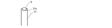
- FIG. 4 shows a second embodiment of the above-described harness durability ensuring rib.
- a groove 21 a that fits at least the bottom of the harness 9 is formed at the top of the rib 21.
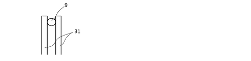
- FIG. 5 shows a third embodiment of the above-mentioned harness durability securing rib.
- a pair of ribs 31 are formed on both sides of the harness. Also in this case, the effect of suppressing the entry of a finger between the harness 9 and the rib 21 can be further enhanced.
- the present invention is not limited to the compressor used in the vehicle air conditioner, and can be applied to any compressor that includes an electromagnetic clutch and fixes a power supply harness to the compressor housing.
Landscapes
- Engineering & Computer Science (AREA)
- Mechanical Engineering (AREA)
- General Engineering & Computer Science (AREA)
- Physics & Mathematics (AREA)
- Electromagnetism (AREA)
- Compressor (AREA)
- Compressors, Vaccum Pumps And Other Relevant Systems (AREA)
- Air-Conditioning For Vehicles (AREA)
- Thermal Sciences (AREA)
Abstract
【課題】電磁クラッチにより、駆動源からの駆動力伝達をオン・オフする圧縮機において、電磁クラッチへ電力供給するハーネスの耐久性を良好に維持する。 【解決手段】圧縮機(1)のフロントハウジング(3)のボス部(3b)に、ハーネス(9)のクラッチハウジング(6a)の接続口(6b)とハーネス(9)が固定されるフロントハウジング(3)の周壁(3a)との間の部分に、ハーネス(9)の配線経路に沿って、ハーネス(9)とフロントハウジング(3)の壁面との間への指の進入を抑制するリブ(12)を配設した。
Description
本発明は、車両用エアコン等に用いられ、圧縮機構を回転駆動する駆動軸の一端部に配設された電磁クラッチにより、エンジン、モータなど駆動源からの駆動力伝達をオン・オフする圧縮機に関する。
この種の圧縮機では、特許文献1に示すように、電磁クラッチに電気接続され、クラッチハウジングから外側に引き出されたハーネスを、クラッチハウジングに連結された圧縮機ハウジングの周壁部位に留め金具等を介して固定している。
ところで、かかるハーネスの取付構造においては、クラッチハウジングに連結される圧縮機ハウジングの前端部の径が、クラッチハウジング及びハーネスが固定される圧縮機ハウジング周壁の径より小さい場合など、ハーネスと圧縮機ハウジングの前端部の外壁との間に、人の指が入ったり、引っ掛かるほどの隙間を生じることがある。
このような構造では、メーカー等の作業者がハーネスを持ち、さらには圧縮機を持ち上げてしまう可能性があり、ハーネスに大きな力が加わって断線等を生じるなど、耐久性の低下が懸念される。
このような構造では、メーカー等の作業者がハーネスを持ち、さらには圧縮機を持ち上げてしまう可能性があり、ハーネスに大きな力が加わって断線等を生じるなど、耐久性の低下が懸念される。
本発明は、このような従来の課題に着目してなされたもので、上記のような構造を有した圧縮機においても、ハーネスを持ちにくくして耐久性低下を抑制した圧縮機を提供することを目的とする。
かかる目的を達成するため、本発明は、
圧縮機構を回転駆動する駆動軸の一端部に配設された電磁クラッチにより、駆動源からの駆動力伝達をオン・オフする圧縮機であって、
前記電磁クラッチに電気接続され、クラッチハウジングから外側に引き出されたハーネスを前記クラッチハウジングに連結された圧縮機ハウジングの前記クラッチハウジングから離間した周壁部位に固定させると共に、
前記圧縮機ハウジングに、前記ハーネスの前記クラッチハウジングからの取出口と前記ハーネスが固定される周壁との間の部分に、前記ハーネスの配線経路に沿って、該ハーネスと前記圧縮機ハウジング壁面との間への指の進入を抑制するリブを配設したことを特徴とする。
圧縮機構を回転駆動する駆動軸の一端部に配設された電磁クラッチにより、駆動源からの駆動力伝達をオン・オフする圧縮機であって、
前記電磁クラッチに電気接続され、クラッチハウジングから外側に引き出されたハーネスを前記クラッチハウジングに連結された圧縮機ハウジングの前記クラッチハウジングから離間した周壁部位に固定させると共に、
前記圧縮機ハウジングに、前記ハーネスの前記クラッチハウジングからの取出口と前記ハーネスが固定される周壁との間の部分に、前記ハーネスの配線経路に沿って、該ハーネスと前記圧縮機ハウジング壁面との間への指の進入を抑制するリブを配設したことを特徴とする。
本発明に係る圧縮機によれば、ハーネスの配線経路に沿って形成されたリブにより、ハーネスと圧縮機ハウジング壁面との間への指の進入が抑制され、ハーネスを持って圧縮機を持つことが抑制されるので、ハーネスの断線等が抑制され耐久性を良好に維持できる。
以下に、本発明の実施形態を、図に基づいて説明する。図1は、一実施形態にかかる車両用エアコンの圧縮機の側面図、図2は、図1を軸周り90°回転させた方向からみた側面図、図3は、圧縮機の前端部の縦断面図である。
圧縮機1は、駆動軸2の軸方向に沿ってフロントハウジング3と、センターハウジング4と、リアハウジング5とが、図示しないボルトを介して相互に締結されている。これら、フロントハウジング3と、センターハウジング4と、リアハウジング5とで、圧縮機ハウジングが形成される。
駆動軸2の前端部はフロントハウジング3の前方に突出しており、電磁クラッチ6が取り付けられている。
駆動軸2の前端部はフロントハウジング3の前方に突出しており、電磁クラッチ6が取り付けられている。
電磁クラッチの入力側部材を構成するプーリ7には、図示しないエンジン、モータ等の駆動源の駆動軸、または該駆動軸に連動する回転軸に取り付けられたプーリ7との間にベルトBが掛けられる。これにより、電磁クラッチ6のオン動作時には、プーリ7を介して入力される回転駆動力により、駆動軸2が回転駆動される。また、電磁クラッチ6のオフ動作時には、駆動源の回転駆動力の圧縮機1の駆動軸2への伝達が遮断される。
センターハウジング4内には、駆動軸2の回転によって容積変化する容積室を有したポンプ機構を備え、該容積室の容積変化によって、容積室内に導入した冷媒ガスを圧縮して吐出させるようになっている。
前記ポンプ機構から吐出された冷媒ガスは、リアハウジング5に形成された吐出室、吐出ポート8を経て外部に導出され、図示しない熱交換器(コンデンサ)に供給される。
前記ポンプ機構から吐出された冷媒ガスは、リアハウジング5に形成された吐出室、吐出ポート8を経て外部に導出され、図示しない熱交換器(コンデンサ)に供給される。
電磁クラッチ6は、電磁コイルを収納したクラッチハウジング6aに、電力供給用ハーネスの接続口6bが配設されている。
そして、電磁コイルと電力供給用のハーネス9とが、前記接続口6bにおいて、その内部のコネクタを介して電気的に接続される。なお、ハーネス9は、前記コネクタとクラッチハウジング6aの径方向外側に向けて接続される。
そして、電磁コイルと電力供給用のハーネス9とが、前記接続口6bにおいて、その内部のコネクタを介して電気的に接続される。なお、ハーネス9は、前記コネクタとクラッチハウジング6aの径方向外側に向けて接続される。
前端部が接続口6bで接続されたハーネス9は、フロントハウジング3の周壁3aに留め金具10を介して固定され、さらに、後方でセンターハウジング4又はリアハウジング5の周壁3aにも、留め金具11を介して固定され、後端部は図示しない電力供給源に接続される。
ところで、本実施形態にかかる圧縮機1では、フロントハウジング3の内部で駆動軸2を前後で支持するベアリングの耐久性を確保するため、ベアリング間の距離が長くなり、その結果、フロントハウジング3の前側のボス部3bが長い形状を有している。
この場合、ボス部3bは、クラッチハウジング6a及びハーネス9が固定されるフロントハウジング9の周壁3a部分より小径に形成されるため、クラッチハウジング6aの背面と、フロントハウジング3の周壁3aとの間には、大きなスペースがある。
したがって、ハーネスの内側に上記スペースを有した場合には、該スペースに指を入れてハーネスを持つことが可能となり、ハーネスを持って圧縮機を持ち上げると、ハーネスに圧縮機の大きな重量が加わり、ハーネスが断線しやすくなるなど耐久性が損なわれることとなる。
そこで、上記の事態を回避するため、下記のように構成される。
本実施形態では、フロントハウジング3のボス部3bに、ハーネス9が接続口6bから径方向外方に引き出されてフロントハウジング3の留め金具10で固定される部位までの配線経路に沿って、ハーネス9に近接(接触を含む)するリブ12を形成する。
本実施形態では、フロントハウジング3のボス部3bに、ハーネス9が接続口6bから径方向外方に引き出されてフロントハウジング3の留め金具10で固定される部位までの配線経路に沿って、ハーネス9に近接(接触を含む)するリブ12を形成する。
リブ12は、ハーネス9の配線方向と直交する方向において、ハーネス9に近接する頂面の幅が、ハーネス9の幅以上の大きさを有するように形成されている。
かかる構成とすれば、ハーネス9とフロントハウジング3壁との隙間が、リブ12によって埋められるため、隙間に手を進入させてハーネス9を持つこと、さらにはハーネス9を持って圧縮機1を持ち上げることが抑制される。
かかる構成とすれば、ハーネス9とフロントハウジング3壁との隙間が、リブ12によって埋められるため、隙間に手を進入させてハーネス9を持つこと、さらにはハーネス9を持って圧縮機1を持ち上げることが抑制される。
これにより、ハーネス9に圧縮機1の重量が加わることを回避でき、ハーネス9の断線等が抑制され耐久性を良好に維持できる。
また、リブ12の頂面の幅をハーネス9の幅(径)以上の大きさを有するようにしたことにより、ハーネス9の底部に指を引っ掛けることも抑制され、ハーネス9の耐久性維持機能をより高めることができる。
また、リブ12の頂面の幅をハーネス9の幅(径)以上の大きさを有するようにしたことにより、ハーネス9の底部に指を引っ掛けることも抑制され、ハーネス9の耐久性維持機能をより高めることができる。
また、上記リブ12は、フロントハウジング3のボス部3bに形成された他の補強用リブと共に、補強機能も合わせて有するものである。換言すれば、通常の補強用リブの一つを、リブ12に代えるだけで済むため、必要最小限の設計変更でよく、重量増加も抑制できる。
図4は、上記ハーネス耐久性確保用のリブの第2の実施形態を示す。
本第2実施形態では、リブ21の頂部に、ハーネス9の少なくとも底部を嵌合する溝21aを形成したものである。かかる構成とすれば、ハーネス9とリブ21との間への指の進入抑制効果をより高めることができる。
本第2実施形態では、リブ21の頂部に、ハーネス9の少なくとも底部を嵌合する溝21aを形成したものである。かかる構成とすれば、ハーネス9とリブ21との間への指の進入抑制効果をより高めることができる。
図5は、上記ハーネス耐久性確保用のリブの第3の実施形態を示す。
本第3実施形態では、リブ31を、ハーネスを挟んで両側に一対形成したものである。
この場合も、ハーネス9とリブ21との間への指の進入抑制効果をより高めることができる。
本第3実施形態では、リブ31を、ハーネスを挟んで両側に一対形成したものである。
この場合も、ハーネス9とリブ21との間への指の進入抑制効果をより高めることができる。
なお、本発明は、上記車両用エアコンに用いられる圧縮機に限らず、電磁クラッチを備え、電力供給用ハーネスを圧縮機ハウジングに固定するいかなる圧縮機にも適用できる。
1 圧縮機
2 駆動軸
3 フロントハウジング
3a 周壁
3b ボス部
4 センターハウジング
5 リアハウジング
6 電磁クラッチ
6a クラッチハウジング
6b 接続口
7 プーリ
9 ハーネス
10 留め金具
12 リブ
21 リブ
21a 溝
31 リブ
2 駆動軸
3 フロントハウジング
3a 周壁
3b ボス部
4 センターハウジング
5 リアハウジング
6 電磁クラッチ
6a クラッチハウジング
6b 接続口
7 プーリ
9 ハーネス
10 留め金具
12 リブ
21 リブ
21a 溝
31 リブ
Claims (9)
- 圧縮機構を回転駆動する駆動軸の一端部に配設された電磁クラッチにより、駆動源からの駆動力伝達をオン・オフする圧縮機であって、
前記電磁クラッチに電気接続され、クラッチハウジングから外側に引き出されたハーネスを前記クラッチハウジングに連結された圧縮機ハウジングの前記クラッチハウジングから離間した周壁部位に固定させると共に、
前記圧縮機ハウジングに、前記ハーネスの前記クラッチハウジングからの取出口と前記ハーネスが固定される周壁との間の部分に、前記ハーネスの配線経路に沿って、該ハーネスと前記圧縮機ハウジング壁面との間への指の進入を抑制するリブを配設したことを特徴とする圧縮機。 - 前記リブは、頂面が前記ハーネスと近接するように形成される、請求項1に記載の圧縮機。
- 前記リブは、前記ハーネス配線方向と直交する方向において、前記頂面の幅が前記ハーネスの幅以上の大きさを有する、請求項2に記載の圧縮機。
- 前記リブは、頂部に前記ハーネスの少なくとも一部を嵌合する溝を有する、請求項1に記載の圧縮機。
- 前記リブは、前記ハーネスを挟んで両側に一対形成される、請求項1に記載の圧縮機。
- 前記ハーネスは、クラッチハウジング壁に配設された接続口で、コネクタとの接続を介して、電磁クラッチと電気接続される、請求項1~請求項5のいずれか1つに記載の圧縮機。
- ハーネスは、前記コネクタとクラッチハウジングの径方向外側に向けて接続される、請求項6に記載の圧縮機。
- 前記圧縮機ハウジングの、前記クラッチハウジングとの連結面から前記ハーネスを固定する周壁に至る部分が、前記クラッチハウジング及び前記圧縮機ハウジングの周壁部分より小径のボス部に形成されている、請求項1~請求項7のいずれか1つに記載の圧縮機。
- 車両用エアコンに用いられる圧縮機である、請求項1~請求項8のいずれか1つに記載の圧縮機。
Priority Applications (3)
| Application Number | Priority Date | Filing Date | Title |
|---|---|---|---|
| DE112015003350.5T DE112015003350T5 (de) | 2014-07-23 | 2015-03-17 | Verdichter |
| US15/328,379 US20170211636A1 (en) | 2014-07-23 | 2015-03-17 | Compressor |
| CN201580040147.6A CN106662089A (zh) | 2014-07-23 | 2015-03-17 | 压缩机 |
Applications Claiming Priority (2)
| Application Number | Priority Date | Filing Date | Title |
|---|---|---|---|
| JP2014-149625 | 2014-07-23 | ||
| JP2014149625A JP6339434B2 (ja) | 2014-07-23 | 2014-07-23 | 圧縮機 |
Publications (1)
| Publication Number | Publication Date |
|---|---|
| WO2016013250A1 true WO2016013250A1 (ja) | 2016-01-28 |
Family
ID=55162789
Family Applications (1)
| Application Number | Title | Priority Date | Filing Date |
|---|---|---|---|
| PCT/JP2015/057794 Ceased WO2016013250A1 (ja) | 2014-07-23 | 2015-03-17 | 圧縮機 |
Country Status (5)
| Country | Link |
|---|---|
| US (1) | US20170211636A1 (ja) |
| JP (1) | JP6339434B2 (ja) |
| CN (1) | CN106662089A (ja) |
| DE (1) | DE112015003350T5 (ja) |
| WO (1) | WO2016013250A1 (ja) |
Families Citing this family (1)
| Publication number | Priority date | Publication date | Assignee | Title |
|---|---|---|---|---|
| KR102018141B1 (ko) | 2016-09-07 | 2019-09-04 | 이병수 | 자가 용융 성분이 소재내에 함침되는 시트 및 이의 제조 방법 |
Citations (6)
| Publication number | Priority date | Publication date | Assignee | Title |
|---|---|---|---|---|
| JPS6163487U (ja) * | 1984-10-01 | 1986-04-30 | ||
| JPH0932774A (ja) * | 1995-07-20 | 1997-02-04 | Sanden Corp | 圧縮機 |
| JP2000249062A (ja) * | 1999-03-02 | 2000-09-12 | Sanden Corp | 圧縮機に接続される線状部品の固定構造及び固定方法 |
| JP2004052714A (ja) * | 2002-07-23 | 2004-02-19 | Calsonic Kansei Corp | 圧縮機の構造 |
| JP2004353631A (ja) * | 2003-05-30 | 2004-12-16 | Toyota Industries Corp | ハイブリッド圧縮機におけるモータ配線の取出し構造 |
| JP2011080458A (ja) * | 2009-10-12 | 2011-04-21 | Denso Corp | 圧縮機 |
Family Cites Families (5)
| Publication number | Priority date | Publication date | Assignee | Title |
|---|---|---|---|---|
| KR100652246B1 (ko) * | 2005-07-20 | 2006-12-01 | 우리산업 주식회사 | 자동차 컴프레서에 결합되는 마그네틱 클러치용 필드코일어셈블리의 전원 연결부 |
| CN1940304A (zh) * | 2005-09-30 | 2007-04-04 | 奇鋐科技股份有限公司 | 风扇电缆线整理结构 |
| KR101336432B1 (ko) * | 2007-05-30 | 2013-12-04 | 한라비스테온공조 주식회사 | 압축기의 리드와이어 고정장치 |
| CN201165979Y (zh) * | 2008-03-14 | 2008-12-17 | 四川天泉汽车空调有限公司 | 压力开关保护式涡旋压缩机 |
| CN203671025U (zh) * | 2014-01-23 | 2014-06-25 | 陕西理工学院 | 用于固定管线的装置 |
-
2014
- 2014-07-23 JP JP2014149625A patent/JP6339434B2/ja active Active
-
2015
- 2015-03-17 DE DE112015003350.5T patent/DE112015003350T5/de not_active Ceased
- 2015-03-17 CN CN201580040147.6A patent/CN106662089A/zh active Pending
- 2015-03-17 WO PCT/JP2015/057794 patent/WO2016013250A1/ja not_active Ceased
- 2015-03-17 US US15/328,379 patent/US20170211636A1/en not_active Abandoned
Patent Citations (6)
| Publication number | Priority date | Publication date | Assignee | Title |
|---|---|---|---|---|
| JPS6163487U (ja) * | 1984-10-01 | 1986-04-30 | ||
| JPH0932774A (ja) * | 1995-07-20 | 1997-02-04 | Sanden Corp | 圧縮機 |
| JP2000249062A (ja) * | 1999-03-02 | 2000-09-12 | Sanden Corp | 圧縮機に接続される線状部品の固定構造及び固定方法 |
| JP2004052714A (ja) * | 2002-07-23 | 2004-02-19 | Calsonic Kansei Corp | 圧縮機の構造 |
| JP2004353631A (ja) * | 2003-05-30 | 2004-12-16 | Toyota Industries Corp | ハイブリッド圧縮機におけるモータ配線の取出し構造 |
| JP2011080458A (ja) * | 2009-10-12 | 2011-04-21 | Denso Corp | 圧縮機 |
Also Published As
| Publication number | Publication date |
|---|---|
| US20170211636A1 (en) | 2017-07-27 |
| JP2016023611A (ja) | 2016-02-08 |
| DE112015003350T5 (de) | 2017-04-06 |
| JP6339434B2 (ja) | 2018-06-06 |
| CN106662089A (zh) | 2017-05-10 |
Similar Documents
| Publication | Publication Date | Title |
|---|---|---|
| JP6377767B2 (ja) | 電動圧縮機 | |
| JP6048347B2 (ja) | 車両用駆動装置 | |
| JP6213500B2 (ja) | 電動ターボ式圧縮機 | |
| CN105899807A (zh) | 电动压缩机的安装结构 | |
| EP2924291B1 (en) | Electric pump | |
| CN105041992A (zh) | V型带式无级传动器 | |
| JP6655637B2 (ja) | 回転電機ユニット | |
| US10298094B2 (en) | Fan cooled motor with dust cleaning vent | |
| JPWO2022074997A5 (ja) | ||
| US9416793B2 (en) | Electronic device | |
| JP6274995B2 (ja) | 往復回転式センサー、およびこれを備えた空気調和機の室内機 | |
| JP6339434B2 (ja) | 圧縮機 | |
| JP2008019800A (ja) | 電動圧縮機用電線保持構造および電動圧縮機用電線保持方法 | |
| JP2012132432A (ja) | インバータ装置一体型電動圧縮機 | |
| JP5977045B2 (ja) | ハイブリッドシステム用モータユニット | |
| CN105705791B (zh) | 电动油泵 | |
| KR102273426B1 (ko) | 전동 압축기 | |
| KR102049877B1 (ko) | 스크루 압축기 | |
| JP6418008B2 (ja) | 電動圧縮機 | |
| US9538889B2 (en) | Radial blower | |
| KR101679227B1 (ko) | 전동 진공 펌프 | |
| JP6090131B2 (ja) | 車載用電動圧縮機 | |
| TWI628360B (zh) | Screw compressor | |
| JP2018021464A (ja) | 両回転スクロール型圧縮機 | |
| JP6181908B2 (ja) | ブロワ |
Legal Events
| Date | Code | Title | Description |
|---|---|---|---|
| 121 | Ep: the epo has been informed by wipo that ep was designated in this application |
Ref document number: 15824062 Country of ref document: EP Kind code of ref document: A1 |
|
| WWE | Wipo information: entry into national phase |
Ref document number: 112015003350 Country of ref document: DE Ref document number: 15328379 Country of ref document: US |
|
| 122 | Ep: pct application non-entry in european phase |
Ref document number: 15824062 Country of ref document: EP Kind code of ref document: A1 |