WO2016010018A1 - Method for preparing single crystal zinc oxide nanoparticles - Google Patents
Method for preparing single crystal zinc oxide nanoparticles Download PDFInfo
- Publication number
- WO2016010018A1 WO2016010018A1 PCT/JP2015/070105 JP2015070105W WO2016010018A1 WO 2016010018 A1 WO2016010018 A1 WO 2016010018A1 JP 2015070105 W JP2015070105 W JP 2015070105W WO 2016010018 A1 WO2016010018 A1 WO 2016010018A1
- Authority
- WO
- WIPO (PCT)
- Prior art keywords
- zinc oxide
- oxide nanoparticles
- solvent
- raw material
- fluid
- Prior art date
Links
Images


Classifications
-
- C—CHEMISTRY; METALLURGY
- C30—CRYSTAL GROWTH
- C30B—SINGLE-CRYSTAL GROWTH; UNIDIRECTIONAL SOLIDIFICATION OF EUTECTIC MATERIAL OR UNIDIRECTIONAL DEMIXING OF EUTECTOID MATERIAL; REFINING BY ZONE-MELTING OF MATERIAL; PRODUCTION OF A HOMOGENEOUS POLYCRYSTALLINE MATERIAL WITH DEFINED STRUCTURE; SINGLE CRYSTALS OR HOMOGENEOUS POLYCRYSTALLINE MATERIAL WITH DEFINED STRUCTURE; AFTER-TREATMENT OF SINGLE CRYSTALS OR A HOMOGENEOUS POLYCRYSTALLINE MATERIAL WITH DEFINED STRUCTURE; APPARATUS THEREFOR
- C30B7/00—Single-crystal growth from solutions using solvents which are liquid at normal temperature, e.g. aqueous solutions
- C30B7/14—Single-crystal growth from solutions using solvents which are liquid at normal temperature, e.g. aqueous solutions the crystallising materials being formed by chemical reactions in the solution
-
- C—CHEMISTRY; METALLURGY
- C30—CRYSTAL GROWTH
- C30B—SINGLE-CRYSTAL GROWTH; UNIDIRECTIONAL SOLIDIFICATION OF EUTECTIC MATERIAL OR UNIDIRECTIONAL DEMIXING OF EUTECTOID MATERIAL; REFINING BY ZONE-MELTING OF MATERIAL; PRODUCTION OF A HOMOGENEOUS POLYCRYSTALLINE MATERIAL WITH DEFINED STRUCTURE; SINGLE CRYSTALS OR HOMOGENEOUS POLYCRYSTALLINE MATERIAL WITH DEFINED STRUCTURE; AFTER-TREATMENT OF SINGLE CRYSTALS OR A HOMOGENEOUS POLYCRYSTALLINE MATERIAL WITH DEFINED STRUCTURE; APPARATUS THEREFOR
- C30B29/00—Single crystals or homogeneous polycrystalline material with defined structure characterised by the material or by their shape
- C30B29/10—Inorganic compounds or compositions
- C30B29/16—Oxides
- C30B29/22—Complex oxides
- C30B29/26—Complex oxides with formula BMe2O4, wherein B is Mg, Ni, Co, Al, Zn, or Cd and Me is Fe, Ga, Sc, Cr, Co, or Al
-
- B—PERFORMING OPERATIONS; TRANSPORTING
- B82—NANOTECHNOLOGY
- B82Y—SPECIFIC USES OR APPLICATIONS OF NANOSTRUCTURES; MEASUREMENT OR ANALYSIS OF NANOSTRUCTURES; MANUFACTURE OR TREATMENT OF NANOSTRUCTURES
- B82Y40/00—Manufacture or treatment of nanostructures
-
- C—CHEMISTRY; METALLURGY
- C01—INORGANIC CHEMISTRY
- C01G—COMPOUNDS CONTAINING METALS NOT COVERED BY SUBCLASSES C01D OR C01F
- C01G9/00—Compounds of zinc
- C01G9/02—Oxides; Hydroxides
-
- C—CHEMISTRY; METALLURGY
- C30—CRYSTAL GROWTH
- C30B—SINGLE-CRYSTAL GROWTH; UNIDIRECTIONAL SOLIDIFICATION OF EUTECTIC MATERIAL OR UNIDIRECTIONAL DEMIXING OF EUTECTOID MATERIAL; REFINING BY ZONE-MELTING OF MATERIAL; PRODUCTION OF A HOMOGENEOUS POLYCRYSTALLINE MATERIAL WITH DEFINED STRUCTURE; SINGLE CRYSTALS OR HOMOGENEOUS POLYCRYSTALLINE MATERIAL WITH DEFINED STRUCTURE; AFTER-TREATMENT OF SINGLE CRYSTALS OR A HOMOGENEOUS POLYCRYSTALLINE MATERIAL WITH DEFINED STRUCTURE; APPARATUS THEREFOR
- C30B29/00—Single crystals or homogeneous polycrystalline material with defined structure characterised by the material or by their shape
- C30B29/10—Inorganic compounds or compositions
- C30B29/16—Oxides
-
- C—CHEMISTRY; METALLURGY
- C30—CRYSTAL GROWTH
- C30B—SINGLE-CRYSTAL GROWTH; UNIDIRECTIONAL SOLIDIFICATION OF EUTECTIC MATERIAL OR UNIDIRECTIONAL DEMIXING OF EUTECTOID MATERIAL; REFINING BY ZONE-MELTING OF MATERIAL; PRODUCTION OF A HOMOGENEOUS POLYCRYSTALLINE MATERIAL WITH DEFINED STRUCTURE; SINGLE CRYSTALS OR HOMOGENEOUS POLYCRYSTALLINE MATERIAL WITH DEFINED STRUCTURE; AFTER-TREATMENT OF SINGLE CRYSTALS OR A HOMOGENEOUS POLYCRYSTALLINE MATERIAL WITH DEFINED STRUCTURE; APPARATUS THEREFOR
- C30B29/00—Single crystals or homogeneous polycrystalline material with defined structure characterised by the material or by their shape
- C30B29/60—Single crystals or homogeneous polycrystalline material with defined structure characterised by the material or by their shape characterised by shape
-
- B—PERFORMING OPERATIONS; TRANSPORTING
- B82—NANOTECHNOLOGY
- B82Y—SPECIFIC USES OR APPLICATIONS OF NANOSTRUCTURES; MEASUREMENT OR ANALYSIS OF NANOSTRUCTURES; MANUFACTURE OR TREATMENT OF NANOSTRUCTURES
- B82Y30/00—Nanotechnology for materials or surface science, e.g. nanocomposites
-
- C—CHEMISTRY; METALLURGY
- C01—INORGANIC CHEMISTRY
- C01P—INDEXING SCHEME RELATING TO STRUCTURAL AND PHYSICAL ASPECTS OF SOLID INORGANIC COMPOUNDS
- C01P2002/00—Crystal-structural characteristics
- C01P2002/60—Compounds characterised by their crystallite size
-
- C—CHEMISTRY; METALLURGY
- C01—INORGANIC CHEMISTRY
- C01P—INDEXING SCHEME RELATING TO STRUCTURAL AND PHYSICAL ASPECTS OF SOLID INORGANIC COMPOUNDS
- C01P2002/00—Crystal-structural characteristics
- C01P2002/70—Crystal-structural characteristics defined by measured X-ray, neutron or electron diffraction data
- C01P2002/72—Crystal-structural characteristics defined by measured X-ray, neutron or electron diffraction data by d-values or two theta-values, e.g. as X-ray diagram
-
- C—CHEMISTRY; METALLURGY
- C01—INORGANIC CHEMISTRY
- C01P—INDEXING SCHEME RELATING TO STRUCTURAL AND PHYSICAL ASPECTS OF SOLID INORGANIC COMPOUNDS
- C01P2004/00—Particle morphology
- C01P2004/01—Particle morphology depicted by an image
- C01P2004/04—Particle morphology depicted by an image obtained by TEM, STEM, STM or AFM
-
- C—CHEMISTRY; METALLURGY
- C01—INORGANIC CHEMISTRY
- C01P—INDEXING SCHEME RELATING TO STRUCTURAL AND PHYSICAL ASPECTS OF SOLID INORGANIC COMPOUNDS
- C01P2004/00—Particle morphology
- C01P2004/60—Particles characterised by their size
- C01P2004/64—Nanometer sized, i.e. from 1-100 nanometer
-
- Y—GENERAL TAGGING OF NEW TECHNOLOGICAL DEVELOPMENTS; GENERAL TAGGING OF CROSS-SECTIONAL TECHNOLOGIES SPANNING OVER SEVERAL SECTIONS OF THE IPC; TECHNICAL SUBJECTS COVERED BY FORMER USPC CROSS-REFERENCE ART COLLECTIONS [XRACs] AND DIGESTS
- Y10—TECHNICAL SUBJECTS COVERED BY FORMER USPC
- Y10S—TECHNICAL SUBJECTS COVERED BY FORMER USPC CROSS-REFERENCE ART COLLECTIONS [XRACs] AND DIGESTS
- Y10S977/00—Nanotechnology
- Y10S977/70—Nanostructure
- Y10S977/773—Nanoparticle, i.e. structure having three dimensions of 100 nm or less
-
- Y—GENERAL TAGGING OF NEW TECHNOLOGICAL DEVELOPMENTS; GENERAL TAGGING OF CROSS-SECTIONAL TECHNOLOGIES SPANNING OVER SEVERAL SECTIONS OF THE IPC; TECHNICAL SUBJECTS COVERED BY FORMER USPC CROSS-REFERENCE ART COLLECTIONS [XRACs] AND DIGESTS
- Y10—TECHNICAL SUBJECTS COVERED BY FORMER USPC
- Y10S—TECHNICAL SUBJECTS COVERED BY FORMER USPC CROSS-REFERENCE ART COLLECTIONS [XRACs] AND DIGESTS
- Y10S977/00—Nanotechnology
- Y10S977/84—Manufacture, treatment, or detection of nanostructure
- Y10S977/895—Manufacture, treatment, or detection of nanostructure having step or means utilizing chemical property
- Y10S977/896—Chemical synthesis, e.g. chemical bonding or breaking
Definitions
- the present invention relates to a method for producing single crystal zinc oxide nanoparticles.
- Zinc oxide nanoparticles are used in a wide range of semiconductors, catalysts, optical devices, sensors, pigments, cosmetics, pharmaceuticals and the like. Since the characteristics of zinc oxide itself remarkably appear by single crystallization, it is expected that these characteristics will be utilized in various fields.
- a single crystal zinc oxide nanoparticle can be produced by a method using a sputtering apparatus (Patent Document 1) or by spraying a zinc oxide precursor solution into a mixing chamber and bringing it into contact with a pulse combustion gas at the same time under a high temperature atmosphere.
- Patent Document 2 A method of obtaining single-crystal zinc oxide nanoparticles by heat treatment (Patent Document 2), a substrate having a crystal plane containing a metal-containing material is immersed in a reaction solution capable of depositing zinc oxide, and single-crystal zinc oxide is obtained.
- Patent Document 3 There is known a method of producing zinc oxide particles by depositing and separating the deposited single crystal zinc oxide from a substrate.
- Patent Documents 1 and 2 a so-called gas phase method is used, and the amount of nanoparticles generated per hour is small, and a high energy device such as an electron beam, plasma, laser, induction heating or the like is used to evaporate the raw material. It is necessary and the yield is low, so it cannot be said that it is suitable for mass production because of production cost. Moreover, since the nanoparticles obtained by these gas phase methods are fine particles of a pure substance, there are problems that they are easily aggregated and fused and the size of the particles varies.
- Patent Document 3 in order to obtain single crystal nanoparticles, a zinc oxide crystal deposited on a substrate is cut from the base using laser irradiation, vibration, ultrasonic wave, nanocutter, or zinc oxide. A post-process for dissolving and removing only the substrate on which crystals are deposited is necessary, and the production efficiency is poor.
- Patent Document 4 it is also known to obtain single-crystal biologically ingestible nanoparticles by depositing nanoparticles between treatment surfaces that are relatively close to and away from each other.
- Patent Document 4 two or more types of forced thin films of fluids to be processed are formed between relatively rotating processing surfaces that can be approached and separated, and single-crystal living body fine particles are generated in the forced thin films. The points to be shown are shown.
- Patent Document 4 it was impossible to apply the invention disclosed in Patent Document 4 when producing single-crystal zinc oxide nanoparticles having completely different physical properties.
- Patent Document 5 and Patent Document 6 a forced thin film of two or more kinds of fluids to be treated is formed between the relatively rotating processing surfaces that can approach and separate, and a fluid containing nanoparticles is obtained. It is disclosed that the pH of the fluid to be treated is adjusted when discharging. However, both adjust the pH of the fluid before mixing, and do not adjust the pH of the fluid after mixing. Therefore, even if the pH of the fluid before mixing is adjusted, if the pH value of the fluid after mixing deviates from basicity due to other reaction conditions, the single crystal zinc oxide nanoparticles are not deposited.
- Patent Document 7 discloses that ceramic fine particles having controlled crystallinity are generated between processing surfaces disposed opposite to each other and capable of approaching / separating at least one rotating relative to the other. ing.
- ceramic fine particles are precipitated by mixing a fluid containing a ceramic raw material liquid in which a ceramic raw material is mixed and / or dissolved in a basic solvent and a fluid containing a ceramic fine particle precipitation solvent between the processing surfaces.
- the crystallinity of the ceramic fine particles deposited in the first step is controlled by utilizing the reaction heat generated by mixing the fluid containing the precipitated fine ceramic particles and the acidic substance. Has been.
- Patent Document 7 does not show that reaction heat is used for precipitation of fine particles, and it has been impossible to stably produce single-crystal zinc oxide nanoparticles.
- the lattice stripes are unclear as shown in FIG. 5 and cannot be said to be a single crystal.
- the reaction conditions described in Example 2 of Patent Document 7 do not drop so much energy that single crystal zinc oxide nanoparticles are generated between the processing surfaces.
- Another object of the present invention is to provide a method for producing single crystal zinc oxide nanoparticles that are stable and suitable for mass production.
- the present invention is a raw material solution in which a zinc oxide precipitation solvent is prepared by uniformly mixing an acidic substance with a solvent containing at least an alcohol, and the zinc oxide precipitation solvent prepared above and a zinc oxide nanoparticle raw material are mixed in a basic solvent.
- the raw material solution that becomes basic by mixing and dissolving the zinc oxide nanoparticle raw material in the solvent is mixed between the relatively rotating processing surfaces that are arranged opposite to each other and that can be moved toward and away from each other.
- a zinc oxide nanoparticle production method in which the mixed fluid on which the zinc oxide nanoparticles are deposited is discharged from between the processing surfaces, the zinc oxide precipitation solvent and the zinc oxide nanoparticles so that the mixed fluid becomes basic.
- the nanoparticle refers to a fine particle having an order of 100 nm or less.
- the shape is not particularly limited, but may be, for example, a substantially spherical shape, a substantially disc shape, a substantially triangular prism shape, a substantially quadrangular prism shape, a substantially polyhedral shape, an elliptical sphere shape, or a substantially cylindrical shape.
- the invention of the present application can be carried out with the mixed fluid having a pH of 8.6 or more and 14 or less, preferably a pH of 12 or more and 14 or less. Moreover, this invention can be implemented as the said pH of the said zinc oxide precipitation solvent is less than 1, and the pH of the said raw material solution exceeds 14.
- the present invention may be carried out using the acidic substance selected from any one of hydrochloric acid, nitric acid and sulfuric acid, and the alcohol is methanol, ethanol, isopropyl alcohol, tert- You may implement using what was chosen from any 1 type in butanol.
- the present invention can be implemented as the basic solvent in which a basic hydroxide is mixed and / or dissolved in a solvent, and the basic hydroxide is an alkali metal hydroxide,
- the alkali metal hydroxide any one of sodium hydroxide, potassium hydroxide, and lithium hydroxide may be used.
- the present invention can be implemented as the zinc oxide nanoparticle raw material is a zinc compound that is soluble in the basic solvent.
- the zinc compound zinc oxide, zinc chloride, zinc nitrate, water You may implement using what was chosen from at least any 1 type among zinc oxide and zinc sulfate.
- the present invention relates to a flow path in which the raw material solution passes between the processing surfaces while forming a thin film fluid, and the zinc oxide precipitation solvent is introduced into the processing solution between the processing surfaces.
- the zinc oxide precipitation solvent and the raw material solution are introduced between the processing surfaces through an opening formed in at least one of the processing surfaces, and the processing surface It can be implemented as being mixed between.
- the zinc oxide precipitation solvent passes between the processing surfaces while forming a thin film fluid
- the raw material solution is a flow path through which the zinc oxide precipitation solvent is introduced between the processing surfaces. Is introduced between the treatment surfaces through an opening formed in at least one of the treatment surfaces through an independent separate introduction path, and the zinc oxide precipitation solvent and the raw material solution are used for the treatment. It can also be implemented as a mixture between surfaces.
- the present invention also uses a rotary disperser to uniformly mix the acidic substance with a solvent containing at least the alcohol.
- the rotary disperser includes a rotor having a plurality of blades and the rotor. And a screen having a plurality of slits, and the rotor and the screen rotate relative to each other so that fluid flows in a minute gap between the inner wall of the screen including the slits and the blades. And a fluid is discharged from the inside to the outside of the screen as an intermittent jet flow through the slit.
- the single crystal ratio of the generated zinc oxide nanoparticles may be controlled by the preparation temperature of the zinc oxide precipitation solvent, and the generation is performed by the stirring energy dropped during the preparation of the zinc oxide precipitation solvent.
- the single crystal ratio of the zinc oxide nanoparticles may be controlled.
- the said zinc oxide precipitation solvent may be prepared at 40 degreeC or more, and the preparation time of the said zinc oxide precipitation solvent is good also as 20 minutes or more.
- the present invention provides a method for producing single crystal zinc oxide nanoparticles that are stable and suitable for mass production without requiring high energy devices such as electron beam, plasma, laser, induction heating, etc. for evaporating the raw material. Was made.
- FIG. 3 A schematic plan view of a first processing surface of the fluid processing apparatus shown in FIG. 3, and (B) is an enlarged view of a main part of the processing surface of the apparatus.
- A) is sectional drawing of the 2nd introducing
- B) is the principal part enlarged view of the processing surface for demonstrating the 2nd introducing
- (A) to (C) are TEM images of the zinc oxide nanoparticles produced in Example 1.
- 2 is a STEM image of zinc oxide nanoparticles produced in Example 1.
- 3 is an XRD measurement result of zinc oxide nanoparticles produced in Example 1.
- 2 is a STEM image of zinc oxide nanoparticles produced in Example 2.
- 4 is a STEM image of zinc oxide nanoparticles produced in Example 3. It is a graph which shows the relationship between the preparation temperature of a raw material solution, and a single crystal ratio.
- acidic substances include inorganic acids such as aqua regia, hydrochloric acid, nitric acid, fuming nitric acid, sulfuric acid and fuming sulfuric acid, and organic acids such as formic acid, acetic acid, chloroacetic acid, dichloroacetic acid, oxalic acid, trifluoroacetic acid and trichloroacetic acid. It is done.
- inorganic acids such as aqua regia, hydrochloric acid, nitric acid, fuming nitric acid, sulfuric acid and fuming sulfuric acid
- organic acids such as formic acid, acetic acid, chloroacetic acid, dichloroacetic acid, oxalic acid, trifluoroacetic acid and trichloroacetic acid. It is done.
- the acidic substance is homogeneously mixed with a solvent containing at least an alcohol.
- the alcohol include linear alcohols such as methanol, ethanol, n-propanol and n-butanol, branched alcohols such as isopropanol, 2-butanol, tert-butanol and 1-methoxy-2-propanol, ethylene glycol and diethylene glycol. And other polyhydric alcohols.
- the zinc oxide precipitation solvent can be carried out by uniformly mixing an acidic substance with a solvent containing at least the alcohol.
- the process (henceforth a preparation step) for preparing a zinc oxide precipitation solvent by mixing an acidic substance homogeneously with the solvent containing at least the said alcohol is mentioned later.
- the pH of the zinc oxide precipitation solvent is desirably less than 1.
- zinc oxide nanoparticle raw material is not particularly limited, zinc alone or a compound thereof can be used. Examples include zinc oxides, nitrides, sulfides, salts (nitrates, sulfates, chlorides, phosphates, carbonates, etc.), hydroxides, complexes, hydrates and organic solvates thereof. Zinc compounds that are soluble in a basic solvent described later are desirable, and it is desirable to use zinc oxide, zinc chloride, zinc nitrate, zinc hydroxide, zinc nitrate, and hydrates thereof. These zinc oxide nanoparticle raw materials may be used alone or in combination of two or more.
- Basic solvent As a basic solvent, it is desirable to carry out the present invention by dissolving the following basic substances in a solvent.
- basic substances include metal hydroxides such as sodium hydroxide and potassium hydroxide, metal alkoxides such as sodium methoxide and sodium isopropoxide, and amine compounds such as triethylamine, diethylaminoethanol, and diethylamine.
- the solvent for mixing and dissolving the basic substance include water, an organic solvent, or a mixed solvent composed of a plurality of them.
- the water include tap water, ion-exchanged water, pure water, ultrapure water, and RO water.
- organic solvent examples include alcohol compound solvents, amide compound solvents, ketone compound solvents, ether compound solvents, and aromatic compounds.
- examples include solvents, carbon disulfide, aliphatic compound solvents, nitrile compound solvents, sulfoxide compound solvents, halogen compound solvents, ester compound solvents, ionic liquids, carboxylic acid compounds, and sulfonic acid compounds.
- the basic solvent may be a basic solvent obtained by mixing and dissolving the above basic substance in the above solvent, or by mixing and dissolving the zinc oxide nanoparticle raw material in the above solvent.
- the basic solvent such as an alkali metal hydroxide or an alkaline earth metal hydroxide is used as the basic solvent. It is desirable to mix and dissolve in a solvent. And as a basic hydroxide, an alkali metal hydroxide is desirable and it is more desirable that they are sodium hydroxide, potassium hydroxide, or lithium hydroxide.
- Dispersants and surfactants can be used according to the purpose and necessity. Although it does not specifically limit, As a surfactant and a dispersing agent, various commercially available products generally used, products, or newly synthesized products can be used. Examples include anionic surfactants, cationic surfactants, nonionic surfactants, dispersants such as various polymers, and the like. These may be used alone or in combination of two or more.
- the above surfactant and dispersant may be contained in either or both of the raw material fluid and the zinc oxide precipitation solvent. Further, the above surfactant and dispersant may be contained in a third fluid different from the raw material solution fluid and the zinc oxide precipitation solvent.
- Preparation step In the preparation step for preparing the zinc oxide precipitation solvent, it is desirable that the acidic substance is homogeneously mixed with a solvent containing at least an alcohol by using a rotary disperser shown below. By using a rotary disperser, homogeneous mixing can be easily performed.
- a rotary disperser shears a fluid such as a rod-shaped, plate-shaped, or propeller-shaped stirrer that rotates in a tank or a screen that rotates relative to the stirrer. It is desirable to use a material that achieves homogeneous mixing by applying force.
- a stirrer disclosed in Japanese Patent No. 5147091 can be applied.
- the rotary disperser may be a batch type or a continuous type.
- emission of the fluid with respect to a stirring tank may be performed continuously, and it may carry out using a continuous mixer, without using a stirring tank.
- the fluid container 104 of the rotary disperser 100 stores a mixture of an acidic substance and a solvent containing at least alcohol, which is a fluid to be treated.
- the rotary disperser 100 includes a processing unit 101 disposed in the fluid to be processed and a rotor 102 disposed in the processing unit 101.
- the processing unit 101 is a hollow housing, and is disposed in the fluid container 104 that stores the fluid to be processed by being supported by the support tube 103.
- the processing unit 101 is provided at the distal end of the support tube 103 and is inserted from the upper part of the fluid container 104 to the lower inside.
- the processing unit 101 is not limited to this example. Even if it supports so that it may protrude upward from the bottom face of the container 104, it can implement.
- the processing unit 101 includes a suction chamber 106 having a suction port 105 that sucks a fluid to be processed from the outside to the inside, and a stirring chamber 107 that is in communication with the suction chamber 106.
- the outer periphery of the stirring chamber 107 is defined by a screen 109 having a plurality of slits 108 serving as discharge ports.
- the suction chamber 106 and the agitation chamber 107 are partitioned by a partition wall 110 that is a partition portion between the two chambers 106 and 107, and are electrically connected via an introduction opening 111 provided in the partition wall 110.
- the base end (upper end in the figure) of the suction chamber 106 is screwed to the front end (lower end of the figure) of the support tube 103, and the base of the stirring chamber 107 (screen 109) is connected to the front end of the suction chamber 106.
- the ends are screwed together, and the partition wall 110 is formed integrally with the lower end of the suction chamber 106, but the configuration and connection state of these members can be variously changed.
- the rotor 102 is a rotating body including a plurality of stirring blades 112 in the circumferential direction, and rotates while maintaining a minute clearance between the stirring blades 112 and the screen 109.
- Various rotation drive structures can be adopted as the structure for rotating the rotor 102.
- the rotor 102 is provided at the tip of the rotating shaft 113 and is rotatably accommodated in the stirring chamber 107. More specifically, the rotating shaft 113 is inserted into the support tube 103. Further, the rotating shaft 113 is disposed so as to reach the stirring chamber 107 from the suction chamber 106 through the opening 111 of the partition wall 110, and the rotor 102 is attached to the tip (lower end in the figure). Accordingly, the rotating shaft 113 becomes a penetrating portion that penetrates the opening 111.
- the base end of the rotating shaft 113 is connected to a rotation driving device such as a motor 114.
- a rotation driving device such as a motor 114.
- the motor 114 it is preferable to use a motor having a control system such as numerical control or a motor placed under the control of a computer.
- the mixing is performed by the shearing force applied to the fluid to be processed existing between the two. Made.
- kinetic energy is given to the fluid to be treated by the rotation of the rotor 102, and the fluid to be treated passes through the slit 108 to be further accelerated to form the intermittent jet flow while forming the intermittent jet flow. It flows out to the outside.
- a liquid-liquid shearing force is generated at the velocity interface, whereby a more uniform dispersion or mixing process is performed.
- a single crystal is prepared by mixing the prepared zinc oxide precipitation solvent and the raw material solution with a fluid processing device provided with a relatively rotating processing surface that is disposed opposite to each other and is capable of approaching and separating.
- a fluid processing device provided with a relatively rotating processing surface that is disposed opposite to each other and is capable of approaching and separating.
- FIGS. 3 to 5 The fluid treatment apparatus shown in FIGS. 3 to 5 is the same as the apparatus described in Patent Document 4.
- U indicates the upper side
- S indicates the lower side.
- R indicates the direction of rotation.
- C indicates the centrifugal force direction (radial direction).
- This fluid processing apparatus includes first and second processing units 10 and 20 that face each other, and at least one processing unit rotates.
- the opposing surfaces of both processing parts 10 and 20 are processing surfaces.
- the first processing unit 10 includes a first processing surface 1
- the second processing unit 20 includes a second processing surface 2.
- Both processing surfaces 1 and 2 are connected to the flow path of the fluid to be processed and constitute a part of the flow path of the fluid to be processed.
- the distance between the processing surfaces 1 and 2 can be changed as appropriate, but is usually adjusted to 1 mm or less, for example, a minute distance of about 0.1 ⁇ m to 50 ⁇ m.
- the fluid to be processed that passes between the processing surfaces 1 and 2 becomes a forced thin film fluid forced by the processing surfaces 1 and 2.
- the apparatus When a plurality of fluids to be processed are processed using this apparatus, the apparatus is connected to the flow path of the first fluid to be processed and forms a part of the flow path of the first fluid to be processed. . Further, this apparatus forms a part of the flow path of the second fluid to be treated, which is different from the first fluid to be treated. Then, this apparatus performs fluid treatment in which both flow paths are merged to mix and react the two fluids to be treated between the processing surfaces 1 and 2 to cause precipitation of fine particles.
- this apparatus includes a first holder 11 that holds the first processing portion 10, a second holder 21 that holds the second processing portion 20, a contact pressure application mechanism, and a rotation.
- a drive mechanism, a first introduction part d1, a second introduction part d2, and a fluid pressure application mechanism p are provided.
- the first processing unit 10 is an annular body, and more specifically a ring-shaped disk.
- the second processing unit 20 is also a ring-shaped disk.
- the materials of the first and second processing parts 10 and 20 are metal, carbon, ceramic, sintered metal, wear-resistant steel, sapphire, other metals subjected to hardening treatment, hard material lining, Those with coating, plating, etc. can be used.
- the processing portions 10 and 20 have the first and second processing surfaces 1 and 2 facing each other mirror-polished, and the arithmetic average roughness is not particularly limited, but preferably 0.01 to 1.0 ⁇ m, and more preferably 0.03 to 0.3 ⁇ m.
- At least one of the first holder 11 and the second holder 21 can be rotated relative to the other holder by a rotation drive mechanism (not shown) such as an electric motor.
- a rotation drive mechanism such as an electric motor.
- the second holder 21 is fixed to the apparatus, and the first holder 11 attached to the rotary shaft 50 of the rotational drive mechanism fixed to the apparatus is rotated and supported by the first holder 11.
- the first processing unit 10 thus rotated rotates with respect to the second processing unit 20.
- the second processing unit 20 may be rotated, or both may be rotated.
- the second processing unit 20 approaches and separates from the first processing unit 10 in the direction of the rotation shaft 50, and the storage unit 41 provided in the second holder 21 2 A portion of the processing portion 20 opposite to the processing surface 2 side is accommodated so that it can appear and disappear.
- the first processing unit 10 may approach or separate from the second processing unit 20, and both the processing units 10 and 20 approach or separate from each other. It may be a thing.
- This accommodating part 41 is a recessed part which accommodates the site
- the accommodating portion 41 accommodates the second processing portion 20 with a sufficient clearance that allows the portion of the second processing portion 20 on the side opposite to the processing surface 2 side to appear.
- the second processing unit 20 may be arranged so that only the parallel movement is possible in the axial direction, but by increasing the clearance, the second processing unit 20 is
- the center line of the processing part 20 may be tilted and displaced so as to break the relationship parallel to the axial direction of the storage part 41. Furthermore, the center line of the second processing part 20 and the storage part 41 may be displaced. The center line may be displaced so as to deviate in the radial direction. As described above, it is desirable to hold the second processing unit 20 by the floating mechanism that holds the three-dimensionally displaceably.
- the above-described fluid to be treated is subjected to both treatment surfaces from the first introduction part d1 and the second introduction part d2 in a state where pressure is applied by a fluid pressure application mechanism p constituted by a pump, potential energy, and the like described later. It is introduced between 1 and 2.
- the first introduction part d1 is a passage provided in the center of the annular second holder 21, and one end of the first introduction part d1 is formed on both processing surfaces from the inside of the annular processing parts 10, 20. It is introduced between 1 and 2.
- the second introduction part d2 supplies the second processed fluid to be reacted with the first processed fluid to the processing surfaces 1 and 2.
- the second introduction portion d2 is a passage provided inside the second processing portion 20, and one end thereof is an opening d20 formed in the second processing surface.
- the first fluid to be processed that has been pressurized by the fluid pressure imparting mechanism p is introduced from the first introduction part d1 into the space inside both the processing parts 10 and 20, and the first processing surface 1 and the second processing surface 2 are supplied. It passes between the processing surfaces 2 and tries to pass outside the processing portions 10 and 20. Between these processing surfaces 1 and 2, the second fluid to be treated pressurized by the fluid pressure applying mechanism p is supplied from the second introduction part d 2, and merges with the first fluid to be treated.
- the fluid containing zinc oxide nanoparticles is discharged from both processing surfaces 1 and 2 to the outside of both processing parts 10 and 20.
- the environment outside both the processing parts 10 and 20 can be set to a negative pressure by a decompression pump.
- the contact surface pressure applying mechanism applies to the processing portion a force that causes the first processing surface 1 and the second processing surface 2 to approach each other.
- the contact pressure applying mechanism is provided in the second holder 21 and biases the second processing portion 20 toward the first processing portion 10.
- the contact surface pressure applying mechanism described above is a force that pushes the first processing surface 1 of the first processing member 10 and the second processing surface 2 of the second processing member 20 in the approaching direction (hereinafter referred to as contact pressure). It is a mechanism for generating. By maintaining a balance between the contact surface pressure and the force that separates the processing surfaces 1 and 2 due to the fluid pressure, the distance between the processing surfaces 1 and 2 is maintained at a predetermined minute interval, and the unit of nm or ⁇ m A thin film fluid having a minute film thickness is generated.
- the contact surface pressure applying mechanism is arranged between the housing part 41 and the second processing part 20. Specifically, one end of the second processing part 20 is locked by the elastic force of the spring 43 whose one end is locked in the hole of the second holder 21 and the other end is locked in the hole of the second processing part.
- the second processing unit 20 is urged in the direction approaching the first processing unit 10 and the second processing unit 20 is subjected to the first processing by the pressure of the urging fluid such as air or oil introduced into the urging fluid introduction unit 44. It is urged in a direction approaching the use portion 10 to apply the contact surface pressure. Any one of the elastic force by the spring 43 and the fluid pressure of the urging fluid may be applied, and other force such as magnetic force or gravity may be used.
- the second processing unit 20 causes the first processing by the separation force generated by the pressure or viscosity of the fluid to be processed which is pressurized by the fluid pressure application mechanism p against the urging force of the contact surface pressure application mechanism. Move away from the working part 10 and leave a minute gap between the processing surfaces.
- the distance between the first processing surface 1 and the second processing surface 2 is set with an accuracy of ⁇ m by the balance between the contact surface pressure and the separation force.
- the separation force in addition to the fluid pressure and viscosity of the fluid to be processed, the centrifugal force due to the rotation of the processing portion, the negative pressure when the negative pressure is applied to the biasing fluid introducing portion 44, the spring 43
- the elastic force in the case of a tension spring can be mentioned.
- This contact surface pressure imparting mechanism may be provided not in the second processing unit 20 but in the first processing unit 10 or in both.
- a separation adjusting surface 23 adjacent to the second processing surface 2 is provided inside the second processing portion 20.
- the separation adjusting surface 23 is formed in an inverted conical surface shape, and the pressure of the fluid to be treated introduced from the first introduction part d1 acts on the separation adjusting surface 23 to cause the second processing part 20 to be the first.
- a force is generated in a direction away from the processing unit 10.
- a proximity adjustment surface 24 is provided inside the second processing portion 20 on the side opposite to the second processing surface 2.
- the proximity adjustment surface 24 is also formed in an inverted conical surface shape, and the pressure of the fluid to be processed introduced from the first introduction portion d1 acts on the proximity adjustment surface 24 to make the second treatment portion 20 the first treatment surface.
- a force in a direction to approach the processing unit 10 is generated.
- the area of the adjustment surface 24 for proximity By adjusting the area of the adjustment surface 24 for proximity, the force in the direction in which the second processing unit 20 is brought close to the first processing unit 10 is adjusted.
- a fluid film is formed by the fluid to be processed by setting the gap amount.
- the proximity adjustment surface 24 may be implemented with a larger area than the separation adjustment surface 23.
- the fluid to be processed becomes a thin film fluid forced by the two processing surfaces 1 and 2 holding the minute gaps and tends to move outside the two processing surfaces 1 and 2 which are annular.
- the mixed fluid to be processed does not move linearly from the inside to the outside of the two processing surfaces 1 and 2, but instead has an annular radius.
- a combined vector of the movement vector in the direction and the movement vector in the circumferential direction acts on the fluid to be processed and moves in a substantially spiral shape from the inside to the outside.
- the rotating shaft 50 is not limited to the one arranged vertically, but may be arranged in the horizontal direction or may be arranged inclined. This is because the fluid to be processed is processed at a fine interval between the processing surfaces 1 and 2 and the influence of gravity can be substantially eliminated or reduced. Further, this contact surface pressure applying mechanism also functions as a buffer mechanism for fine vibration and rotational alignment when used in combination with a floating mechanism that holds the second processing portion 20 in a displaceable manner.
- the first processing surface 1 of the first processing portion 10 is formed with a groove-like recess 13 extending from the center side of the first processing portion 10 to the outside, that is, in the radial direction. May be implemented.
- the planar shape of the recess 13 is curved or spirally extending on the first processing surface 1, or is not illustrated, but extends straight outward, L It may be bent or curved into a letter shape or the like, continuous, intermittent, or branched.
- the concave portion 13 can be implemented as one formed on the second processing surface 2, and can also be implemented as one formed on both the first and second processing surfaces 1, 2. By forming such a concave portion 13, the micropump effect can be obtained, and there is an effect that the fluid to be processed can be sucked between the first and second processing surfaces 1 and 2.
- the base end of the recess 13 reaches the inner periphery of the first processing unit 10.
- the tip of the recess 13 extends toward the outer peripheral surface of the first processing surface 1, and the depth gradually decreases from the base end toward the tip.
- a flat surface 16 without the recess 13 is provided between the tip of the recess 13 and the outer peripheral surface of the first processing surface 1.
- the opening d20 is preferably provided at a position facing the flat surface 16 of the first processing surface 1.
- the distance n in the radial direction from the tip of the recess 13 provided in the first processing surface 1 is about 0.5 mm or more.
- the shape of the opening d20 may be circular as shown in FIGS. 4B and 5B, and as shown by a dotted line in FIG. 4B, the processing surface is a ring-shaped disk. A concentric ring shape surrounding the central opening of the two may be used.
- the second introduction part d2 can have directionality.
- the introduction direction from the opening d20 of the second processing surface 2 is inclined with respect to the second processing surface 2 at a predetermined elevation angle ( ⁇ 1).
- the elevation angle ( ⁇ 1) is set to be more than 0 degrees and less than 90 degrees, and in the case of a reaction with a higher reaction rate, it is preferably set at 1 to 45 degrees.
- the introduction direction from the opening d ⁇ b> 20 of the second processing surface 2 has directionality in a plane along the second processing surface 2.
- the introduction direction of the second fluid to be processed is an outward direction away from the center in the radial direction component of the processing surface, and with respect to the rotation direction of the fluid between the rotating processing surfaces. In the component, it is the forward direction.
- a line segment in the radial direction passing through the opening d20 and extending outward is defined as a reference line g and has a predetermined angle ( ⁇ 2) from the reference line g to the rotation direction R. This angle ( ⁇ 2) is also preferably set to more than 0 degree and less than 90 degrees.
- This angle ( ⁇ 2) can be changed and carried out according to various conditions such as the type of fluid, reaction speed, viscosity, and rotational speed of the processing surface.
- the second introduction part d2 may not have any directionality.
- the number of fluids to be processed and the number of flow paths are two, but may be three or more.
- the second fluid to be processed is introduced between the processing surfaces 1 and 2 from the second introduction part d2, but this introduction part may be provided in the first treatment part 10, It may be provided.
- the shape, size, and number of the opening for introduction provided in each processing portion are not particularly limited, and can be appropriately changed. Further, an opening for introduction may be provided immediately before or between the first and second processing surfaces 1 and 2 or further upstream.
- a 2nd to-be-processed fluid is introduce
- the first fluid to be treated may be introduced.
- the expressions “first” and “second” in each fluid have only an implication for identification that they are the nth of a plurality of fluids, and a third or higher fluid may exist.
- the zinc oxide precipitation solvent is strongly acidic and the raw material solution is strongly basic. Further, the pH of the zinc oxide precipitation solvent is less than 1, and the pH of the raw material solution may exceed 14. More preferable.
- the first processing surface 1 and the second processing surface 2 facing each other of the processing portions 10 and 20 are both annular, thereby forming an annular space between the processing surfaces 1 and 2.
- only one for example, only the second processing surface 2 may be annular, and the other (for example, the first processing surface 1) may be flat.
- the first fluid to be treated is introduced inside the annular space between the processing surfaces 1 and 2 as the first introduction part d1, and the introduced first fluid to be treated is the first introduction part d1.
- the annular outer side may be upstream and the annular inner side may be downstream.
- the second fluid to be treated is introduced from the opening d20 of the second introduction part d2 and is flowed with the annular outer side as the downstream, but conversely, the annular inner side is caused to flow with the downstream. Also good.
- the mixed fluid after mixing the raw material fluid and the zinc oxide precipitation solvent using the fluid treatment apparatus is basic, preferably pH 8.6 to 14, more preferably pH 12 to 14. Also, when the pH of the mixed fluid after mixing the raw material fluid and the zinc oxide precipitation solvent is greater than 8.6, a zinc compound (zinc sulfate, zinc hydroxide, etc.) different from zinc oxide is precipitated. Less. In particular, when the pH of the mixed fluid is 12 or more and 14 or less, all of the obtained zinc oxide nanoparticles are preferably single crystallized. Moreover, it does not specifically limit about the adjustment method of pH of a mixed fluid. Adjust the prescription of the zinc oxide precipitation solvent and / or the raw material solution so that the pH of the mixed fluid is in the above range, or change the flow rate, temperature, and operating conditions of the fluid treatment device. Can be implemented.
- a zinc oxide precipitation solvent by uniformly mixing an acidic substance with a solvent containing at least an alcohol. Homogenous mixing is performed by stirring using a rotary disperser, but generally stirring energy is defined by Equation 1.
- Stirring energy Np ⁇ ⁇ ⁇ n 3 ⁇ d 5 ⁇ t (Formula 1)
- Np Power factor (a dimensionless constant calculated from experimental data)
- ⁇ Density of zinc oxide precipitation solvent
- n Number of rotor rotations
- d Rotor diameter
- Stirring time By changing at least one of the parameters ⁇ , n, d, and t in Formula 1, the single crystal ratio of the generated zinc oxide nanoparticles can be controlled.
- the liquid A refers to the first fluid to be treated introduced from the first introduction part d1 of the apparatus shown in FIG. 3, and the liquid B is also from the second introduction part d2 of the apparatus.
- the 2nd to-be-processed fluid introduced is pointed out.
- Example 1 As the rotary disperser 100 shown in FIG. 1, a zinc oxide precipitation solvent and a raw material solution were prepared using CLEARMIX (manufactured by M Technique). Specifically, an acidic substance and alcohol are added to the CLEARMIX based on the prescription of the zinc oxide precipitation solvent shown in Example 1 of Table 1, and in a nitrogen atmosphere, the preparation temperature is 50 ° C. and the rotor rotation speed is 10,000 rpm. The mixture was homogeneously mixed by stirring for a minute to prepare a zinc oxide precipitation solvent.
- CLEARMIX manufactured by M Technique
- the zinc oxide nanoparticle raw material and the basic solvent were added to the CLEARMIX, and the rotation speed of the rotor was adjusted at the preparation temperature shown in Table 1 in a nitrogen atmosphere.
- the mixture was homogeneously mixed by stirring at 20000 rpm for 30 minutes, and the raw material solution was prepared by dissolving the raw material of zinc oxide nanoparticles in a basic solvent.
- ZnO zinc oxide
- ZnCl 2 zinc chloride MeOH is methanol
- EtOH is ethanol
- IPA is isopropanol
- KOH potassium hydroxide
- NaOH sodium hydroxide
- Li (OH ) 2 lithium hydroxide
- H 2 SO 4 sulfuric acid
- HNO 3 is nitric acid
- HCl hydrochloric acid.
- a zinc oxide precipitation solvent is used as a first processing fluid as a raw material solution as a second processing fluid.
- a zinc oxide precipitation solvent is used as a first processing fluid as a raw material solution as a second processing fluid.
- a discharge liquid containing zinc oxide nanoparticles (hereinafter, zinc oxide nanoparticle dispersion liquid) was discharged from between the processing surfaces 1 and 2 of the fluid processing apparatus.
- the introduction temperatures of the first fluid to be treated and the second fluid to be treated were measured immediately before the introduction of the treatment apparatus (more specifically, immediately before being introduced between the treatment surfaces 1 and 2).
- the pH of the zinc oxide nanoparticle dispersion discharged from between the processing surfaces 1 and 2 of the fluid processing apparatus was measured so that the pH of the discharged liquid became basic.
- a pH meter of model number D-51 manufactured by HORIBA was used for pH measurement. Before introducing each fluid to be treated into the fluid treatment apparatus, the pH of the fluid to be treated was measured at room temperature. Moreover, the pH of the zinc oxide nanoparticle dispersion liquid discharged from the apparatus was measured at room temperature.
- Dry powder and wet cake samples were prepared from the zinc oxide nanoparticle dispersion liquid discharged from the fluid processing apparatus.
- the production method was carried out in accordance with a conventional method of this type of treatment.
- the discharged zinc oxide nanoparticle dispersion was collected and filtered with a Nutsche lined with hard filter paper, and then washed and filtered repeatedly. Separation was performed twice, and one was dried to obtain a dry powder.
- the other was subjected to MeOH substitution and then filtered through a Nutsche lined with hard filter paper to obtain a wet cake sample.
- Example preparation for TEM observation and TEM observation result The washed zinc oxide nanoparticle wet cake obtained in the examples was dispersed in ethylene glycol and further diluted 100 times with methyl ethyl ketone (MEK). The obtained diluted solution was dropped on the collodion film and dried to obtain a sample for TEM observation.
- MEK methyl ethyl ketone
- sample preparation for STEM observation and TEM observation result A dispersion obtained by dispersing the zinc oxide nanoparticle wet cake after the washing treatment obtained in Examples in ethylene glycol was dropped onto a microgrid and dried to obtain a sample for STEM observation.
- FIG. 6A to 6C show TEM images of the zinc oxide nanoparticles produced in Example 1
- FIG. 7 shows STEM images of the zinc oxide nanoparticles produced in Example 1.
- FIG. As a result of TEM and STEM observation, zinc oxide nanoparticles having a primary particle diameter of about 3 to 8 nm were observed.
- X-ray diffraction measurement For the X-ray diffraction (XRD) measurement, a powder X-ray diffraction measurement apparatus X′Pert PRO MPD (manufactured by XRD Spectris Panalytical Division) was used. The measurement conditions were: measurement range: 10 to 100 [° 2 Theta] Cu counter cathode, tube voltage 45 kV, tube current 40 mA, and scanning speed 1.6 ° / min.
- XRD measurement results XRD measurement was performed using the dry powder of zinc oxide nanoparticles obtained in each Example.
- the XRD measurement result of Example 1 is shown in FIG.
- a peak corresponding to zinc oxide was observed, and it was confirmed that zinc oxide was produced.
- the crystallite diameter was calculated from the Scherrer equation using the measurement result of the silicon polycrystalline plate.
- the zinc oxide nanoparticles obtained in the examples were obtained by electron microscope observation or TEM observation using a transmission electron microscope (TEM) or a scanning electron microscope (SEM). Examples include a method of comparing the particle diameter and the measurement result of crystallites using XRD.
- the criterion for determining whether or not each particle is a single crystal is that a lattice stripe (atom arrangement in the crystal) is observed in one direction is recognized as a single crystal, and the lattice stripe is Those that are disturbed or have grain boundaries are recognized as not being single crystals.
- Examples 2 to 10 Comparative Examples 1 and 2
- each formulation of zinc oxide precipitation solvent and raw material solution listed in Table 1 introduction flow rate, introduction temperature was carried out, and from the zinc oxide nanoparticle dispersion discharged from the fluid treatment device, A dry powder and a wet cake sample were prepared, a sample was prepared in the same procedure as in Example 1, and observed and measured. The results shown in Table 1 were obtained. The conditions not listed in Table 1 are the same as in Example 1.
- Example 2 to 10 in which the discharged liquid was basic it was found that the discharged zinc oxide nanoparticle dispersion liquid contained single crystal zinc oxide nanoparticles. did. That is, single crystal zinc oxide nanoparticles were produced in Examples 2 to 10.
- Example 1 Example 2, Example 3, Example 4, Example 6, and Example 8.
- Example 1 Example 2, Example 3, and Example 6
- the pH of the discharge liquid was 8.6 or higher
- the single crystallization ratio was relatively high.
- Example 1 Example 2, Example 3, and Example 6
- all the observed zinc oxide nanoparticles were single crystals.
- the relationship between the preparation temperature of a raw material solution and a single crystal ratio is as FIG. 11, and when the preparation temperature of a raw material solution is 50 degreeC or more, a single crystal ratio improves and the preparation temperature of a raw material solution is 75 degreeC. In this case, the single crystal ratio was further improved.
- the number described in FIG. 11 shows the Example number of Table 1.
- each formulation of the zinc oxide precipitation solvent and the raw material solution, preparation of the raw material solution, introduction flow rate to the fluid treatment device, introduction temperature, and operating conditions of the fluid treatment device are the same as those in the first embodiment, and the zinc oxide precipitation solvent Nanoparticles were precipitated by changing only the preparation time and the preparation temperature in the preparation conditions, and the single crystal ratio was calculated in the same manner as in Examples 1 to 10.
- Table 2 the results from Rank 1 to Rank 4 were obtained. It was.
- the zinc oxide nanoparticles obtained under the conditions of a preparation time of 30 minutes and a preparation temperature of 50 ° C. are Example 1 in Table 1.
- the single crystal zinc oxide nanoparticles can be precipitated by homogeneously mixing the acidic substance with a solvent containing at least alcohol.
- a solvent containing at least alcohol a solvent containing at least alcohol.
- Table 2 above is an example in which the stirring energy is increased or decreased depending on the preparation time t.
- the single crystal ratio of the obtained single crystal zinc oxide nanoparticles can be controlled by the amount of stirring energy dropped during the preparation of the zinc oxide precipitation solvent.
- Example 1 in order to obtain a single crystal ratio of 100%, the zinc oxide precipitation solvent was prepared by stirring at a rotor speed of 10,000 rpm for 30 minutes. For example, the rotor speed was half that of Example 1.
- the stirring energy dropped during the preparation of the zinc precipitation solvent becomes equal, and the same result as in Example 1 is obtained. Needless to say, if the expression 1 is satisfied, both the preparation time and the rotor diameter may be set.
- the preparation temperature is determined by the parameters ⁇ , n, d, t of the above expression 1 in controlling the single crystal ratio. Must be set independently.
Abstract
Description
特許文献4においては、接近離反可能な相対的に回転する処理用面間で、2種類以上の被処理流動体の強制薄膜を形成し、この強制薄膜中において単結晶の生体摂取物微粒子を生成させる点について示されている。ところが、物性の全く異なる酸化亜鉛ナノ粒子について単結晶のものを製造する際に、特許文献4に開示の発明を適応することは不可能であった。 On the other hand, it is also known to obtain single-crystal biologically ingestible nanoparticles by depositing nanoparticles between treatment surfaces that are relatively close to and away from each other (Patent Document 4).
In
この場合、処理用面間において、まず、セラミックス原料を塩基性溶媒に混合及び/または溶解したセラミックス原料液を含む流体と、セラミックス微粒子析出用溶媒を含む流体とを混合してセラミックス微粒子を析出させる。そして、次工程では、析出させたセラミックス微粒子を含む流体と酸性物質とを混合することによって発生する反応熱を利用して、最初の工程で析出されたセラミックス微粒子の結晶性を制御することが示されている。
しかしながら、特許文献7では、微粒子の析出の際に反応熱を利用することは示されておらず、単結晶の酸化亜鉛ナノ粒子を安定的に製造することは不可能であった。特許文献7の実施例では、図5に示されている通り格子縞が不明瞭であり、単結晶であるとは言えない。また、特許文献7の実施例2に記載されている反応条件は、処理用面間で単結晶の酸化亜鉛ナノ粒子が生成されるほど、大きなエネルギーが投下されるものではない 。
In this case, first, ceramic fine particles are precipitated by mixing a fluid containing a ceramic raw material liquid in which a ceramic raw material is mixed and / or dissolved in a basic solvent and a fluid containing a ceramic fine particle precipitation solvent between the processing surfaces. . In the next step, it is shown that the crystallinity of the ceramic fine particles deposited in the first step is controlled by utilizing the reaction heat generated by mixing the fluid containing the precipitated fine ceramic particles and the acidic substance. Has been.
However,
なお、本発明において、ナノ粒子とは100nmオーダー以下の微小な粒子をいう。その形状は特に限定されないが、たとえば、略球状、略円盤状、略三角柱状、略四角柱状、略多面体状、楕円球状、略円柱状などであってもよい。 The present invention is a raw material solution in which a zinc oxide precipitation solvent is prepared by uniformly mixing an acidic substance with a solvent containing at least an alcohol, and the zinc oxide precipitation solvent prepared above and a zinc oxide nanoparticle raw material are mixed in a basic solvent. Alternatively, the raw material solution that becomes basic by mixing and dissolving the zinc oxide nanoparticle raw material in the solvent is mixed between the relatively rotating processing surfaces that are arranged opposite to each other and that can be moved toward and away from each other. A zinc oxide nanoparticle production method in which the mixed fluid on which the zinc oxide nanoparticles are deposited is discharged from between the processing surfaces, the zinc oxide precipitation solvent and the zinc oxide nanoparticles so that the mixed fluid becomes basic. A method for producing single crystal zinc oxide nanoparticles by mixing the raw material solution between the processing surfaces and generating zinc oxide nanoparticles by an acid-base reaction by mixing the acidic substance and the basic solvent To provide.
In the present invention, the nanoparticle refers to a fine particle having an order of 100 nm or less. The shape is not particularly limited, but may be, for example, a substantially spherical shape, a substantially disc shape, a substantially triangular prism shape, a substantially quadrangular prism shape, a substantially polyhedral shape, an elliptical sphere shape, or a substantially cylindrical shape.
また、本願発明は、上記酸化亜鉛析出溶媒のpHが1未満であり、かつ、上記原料溶液のpHが14を超えるものとして実施することができる。 The invention of the present application can be carried out with the mixed fluid having a pH of 8.6 or more and 14 or less, preferably a pH of 12 or more and 14 or less.
Moreover, this invention can be implemented as the said pH of the said zinc oxide precipitation solvent is less than 1, and the pH of the said raw material solution exceeds 14.
また、上記酸化亜鉛析出溶媒の調製温度によって、上記生成される酸化亜鉛ナノ粒子の単結晶比率を制御してもよく、上記酸化亜鉛析出溶媒の調製時に投下される撹拌エネルギーによって、上記生成される酸化亜鉛ナノ粒子の単結晶比率を制御してもよい。ここで、単結晶比率とは、生成された酸化亜鉛ナノ粒子を電子顕微鏡で観察し、観察した酸化亜鉛ナノ粒子の数A(個)とそのうち単結晶として観察された酸化亜鉛ナノ粒子の数B(個)から単結晶比率=B/A×100(%)により算出したものである。
そして、上記酸化亜鉛析出溶媒を40℃以上で調製するようにしてもよく、上記酸化亜鉛析出溶媒の調製時間を20分以上としてもよい。 The present invention also uses a rotary disperser to uniformly mix the acidic substance with a solvent containing at least the alcohol. The rotary disperser includes a rotor having a plurality of blades and the rotor. And a screen having a plurality of slits, and the rotor and the screen rotate relative to each other so that fluid flows in a minute gap between the inner wall of the screen including the slits and the blades. And a fluid is discharged from the inside to the outside of the screen as an intermittent jet flow through the slit.
In addition, the single crystal ratio of the generated zinc oxide nanoparticles may be controlled by the preparation temperature of the zinc oxide precipitation solvent, and the generation is performed by the stirring energy dropped during the preparation of the zinc oxide precipitation solvent. The single crystal ratio of the zinc oxide nanoparticles may be controlled. Here, the single crystal ratio means that the generated zinc oxide nanoparticles are observed with an electron microscope, the number A (pieces) of zinc oxide nanoparticles observed, and the number B of zinc oxide nanoparticles observed as a single crystal among them. Calculated from (pieces) by the single crystal ratio = B / A × 100 (%).
And the said zinc oxide precipitation solvent may be prepared at 40 degreeC or more, and the preparation time of the said zinc oxide precipitation solvent is good also as 20 minutes or more.
酸性物質としては、王水、塩酸、硝酸、発煙硝酸、硫酸、発煙硫酸などの無機酸や、ギ酸、酢酸、クロロ酢酸、ジクロロ酢酸、シュウ酸、トリフルオロ酢酸、トリクロロ酢酸などの有機酸が挙げられる。 (Acid substance)
Examples of acidic substances include inorganic acids such as aqua regia, hydrochloric acid, nitric acid, fuming nitric acid, sulfuric acid and fuming sulfuric acid, and organic acids such as formic acid, acetic acid, chloroacetic acid, dichloroacetic acid, oxalic acid, trifluoroacetic acid and trichloroacetic acid. It is done.
酸化亜鉛析出溶媒を調製するために、上記酸性物質を少なくともアルコールを含む溶媒に均質に混合させる。
アルコールとしては、例えばメタノール、エタノール、n-プロパノール、n-ブタノールなどの直鎖アルコール、イソプロパノール、2-ブタノール、tert-ブタノール、1-メトキシ-2-プロパノール等の分枝状アルコール、エチレングリコール、ジエチレングリコール等の多価アルコール等が挙げられる。 (Solvent containing at least alcohol)
In order to prepare the zinc oxide precipitation solvent, the acidic substance is homogeneously mixed with a solvent containing at least an alcohol.
Examples of the alcohol include linear alcohols such as methanol, ethanol, n-propanol and n-butanol, branched alcohols such as isopropanol, 2-butanol, tert-butanol and 1-methoxy-2-propanol, ethylene glycol and diethylene glycol. And other polyhydric alcohols.
酸化亜鉛析出溶媒は、酸性物質を少なくとも上記アルコールを含む溶媒に均質に混合して実施することができる。なお、酸性物質を少なくとも上記アルコールを含む溶媒に均質に混合させることで酸化亜鉛析出溶媒を調製するための工程(以下、調製ステップ)については、後述する。その際、酸化亜鉛析出溶媒を40℃以上で調製することが望ましく、酸化亜鉛析出溶媒の調製時間を20分以上とすることが望ましい。また、酸化亜鉛析出溶媒のpHは1未満であることが望ましい。 (Zinc oxide precipitation solvent)
The zinc oxide precipitation solvent can be carried out by uniformly mixing an acidic substance with a solvent containing at least the alcohol. In addition, the process (henceforth a preparation step) for preparing a zinc oxide precipitation solvent by mixing an acidic substance homogeneously with the solvent containing at least the said alcohol is mentioned later. At that time, it is desirable to prepare the zinc oxide precipitation solvent at 40 ° C. or higher, and the preparation time of the zinc oxide precipitation solvent is preferably 20 minutes or longer. Further, the pH of the zinc oxide precipitation solvent is desirably less than 1.
酸化亜鉛ナノ粒子原料は、特に限定されないが、亜鉛単体やその化合物を用いることができる。一例として、亜鉛の酸化物、窒化物、硫化物、塩(硝酸塩、硫酸塩、塩化物、リン酸塩、炭酸塩など)、水酸化物、錯体や、それらの水和物や有機溶媒和物などが挙げられ、後述する塩基性溶媒に可溶な亜鉛化合物が望ましく、酸化亜鉛、塩化亜鉛、硝酸亜鉛、水酸化亜鉛、硝酸亜鉛やそれらの水和物を用いることが望ましい。これらの酸化亜鉛ナノ粒子原料は、単独で用いてもよく、2種以上を併用してもよい。 (Zinc oxide nanoparticle raw material)
Although the zinc oxide nanoparticle raw material is not particularly limited, zinc alone or a compound thereof can be used. Examples include zinc oxides, nitrides, sulfides, salts (nitrates, sulfates, chlorides, phosphates, carbonates, etc.), hydroxides, complexes, hydrates and organic solvates thereof. Zinc compounds that are soluble in a basic solvent described later are desirable, and it is desirable to use zinc oxide, zinc chloride, zinc nitrate, zinc hydroxide, zinc nitrate, and hydrates thereof. These zinc oxide nanoparticle raw materials may be used alone or in combination of two or more.
塩基性溶媒としては、以下の塩基性物質を溶媒に溶解させて本発明を実施することが望ましい。
塩基性物質としては、水酸化ナトリウムや水酸化カリウムなどの金属水酸化物、ナトリウムメトキシドやナトリウムイソプロポキシドのような金属アルコキシド、さらにトリエチルアミンやジエチルアミノエタノール、ジエチルアミンなどのアミン系化合物などが挙げられる。
塩基性物質を混合、溶解させるための溶媒としては、例えば水や有機溶媒、またはそれらの複数からなる混合溶媒が挙げられる。上記水としては、水道水やイオン交換水、純水や超純水、RO水などが挙げられ、有機溶媒としては、アルコール化合物溶媒、アミド化合物溶媒、ケトン化合物溶媒、エーテル化合物溶媒、芳香族化合物溶媒、二硫化炭素、脂肪族化合物溶媒、ニトリル化合物溶媒、スルホキシド化合物溶媒、ハロゲン化合物溶媒、エステル化合物溶媒、イオン性液体、カルボン酸化合物、スルホン酸化合物などが挙げられる。上記の溶媒はそれぞれ単独で使用しても良く、または複数以上を混合して使用しても良い。
塩基性溶媒としては、上記の塩基性物質を上記の溶媒に混合、溶解して塩基性溶媒としたものであっても良いし、酸化亜鉛ナノ粒子原料を上記の溶媒に混合、溶解することによって、結果的に原料溶液が塩基性となる場合であっても実施できるが、塩基性溶媒として、アルカリ金属の水酸化物やアルカリ土類金属の水酸化物などの塩基性水酸化物を上記の溶媒に混合、溶解することが望ましい。そして、塩基性水酸化物としては、アルカリ金属水酸化物が望ましく、水酸化ナトリウム、水酸化カリウム又は水酸化リチウムであることがより望ましい。 (Basic solvent)
As a basic solvent, it is desirable to carry out the present invention by dissolving the following basic substances in a solvent.
Examples of basic substances include metal hydroxides such as sodium hydroxide and potassium hydroxide, metal alkoxides such as sodium methoxide and sodium isopropoxide, and amine compounds such as triethylamine, diethylaminoethanol, and diethylamine. .
Examples of the solvent for mixing and dissolving the basic substance include water, an organic solvent, or a mixed solvent composed of a plurality of them. Examples of the water include tap water, ion-exchanged water, pure water, ultrapure water, and RO water. Examples of the organic solvent include alcohol compound solvents, amide compound solvents, ketone compound solvents, ether compound solvents, and aromatic compounds. Examples include solvents, carbon disulfide, aliphatic compound solvents, nitrile compound solvents, sulfoxide compound solvents, halogen compound solvents, ester compound solvents, ionic liquids, carboxylic acid compounds, and sulfonic acid compounds. Each of the above solvents may be used alone or in combination of two or more.
The basic solvent may be a basic solvent obtained by mixing and dissolving the above basic substance in the above solvent, or by mixing and dissolving the zinc oxide nanoparticle raw material in the above solvent. As a result, it can be carried out even when the raw material solution becomes basic, but the basic solvent such as an alkali metal hydroxide or an alkaline earth metal hydroxide is used as the basic solvent. It is desirable to mix and dissolve in a solvent. And as a basic hydroxide, an alkali metal hydroxide is desirable and it is more desirable that they are sodium hydroxide, potassium hydroxide, or lithium hydroxide.
酸化亜鉛ナノ粒子原料を塩基性溶媒に溶解して原料溶液とすることが望ましい。なお、混合や溶解の際に、酸化亜鉛析出溶媒同様、後述する調製ステップにより、両者を均質に混合させる。その際、原料溶液を50℃以上で調製することが望ましく、さらに、75℃以上で調製することがより望ましい。また、原料溶液のpHは14を超えることが望ましい。 (Raw material solution)
It is desirable to dissolve the zinc oxide nanoparticle raw material in a basic solvent to form a raw material solution. In addition, at the time of mixing and dissolving, like the zinc oxide precipitation solvent, both are mixed homogeneously by a preparation step described later. At that time, it is desirable to prepare the raw material solution at 50 ° C. or higher, and it is more desirable to prepare at 75 ° C. or higher. Further, the pH of the raw material solution is desirably more than 14.
本発明においては、目的や必要に応じて各種の分散剤や界面活性剤を用いる事ができる。特に限定されないが、界面活性剤及び分散剤としては一般的に用いられる様々な市販品や、製品または新規に合成したものなどを使用できる。一例として、陰イオン性界面活性剤、陽イオン性界面活性剤、非イオン性界面活性剤や、各種ポリマーなどの分散剤などを挙げることができる。これらは単独で使用してもよく、2種以上を併用してもよい。 (Dispersant etc.)
In the present invention, various dispersants and surfactants can be used according to the purpose and necessity. Although it does not specifically limit, As a surfactant and a dispersing agent, various commercially available products generally used, products, or newly synthesized products can be used. Examples include anionic surfactants, cationic surfactants, nonionic surfactants, dispersants such as various polymers, and the like. These may be used alone or in combination of two or more.
酸化亜鉛析出溶媒を調製するための調製ステップは、以下に示す回転式分散機を用いて、酸性物質を少なくともアルコールを含む溶媒に均質に混合させることが望ましい。回転式分散機を用いることにより、均質な混合を容易に行うことが可能となる。 (Preparation step)
In the preparation step for preparing the zinc oxide precipitation solvent, it is desirable that the acidic substance is homogeneously mixed with a solvent containing at least an alcohol by using a rotary disperser shown below. By using a rotary disperser, homogeneous mixing can be easily performed.
図1及び図2に示すように、この実施の形態に係る回転式分散機100の流体容器104には、被処理流動体である、酸性物質と少なくともアルコールを含む溶媒の混合物が収納されている。また、回転式分散機100は、被処理流動体中に配される処理部101と、処理部101内に配置されたローター102とを備えるものである。 (Explanation of FIGS. 1 and 2)
As shown in FIGS. 1 and 2, the
詳細なメカニズムは不明であるが、酸化亜鉛析出溶媒を調製する際に、酸性物質を少なくともアルコールを含む溶媒に均質に混合させないと、単結晶でない酸化亜鉛ナノ粒子が析出されてしまう。 In the
Although the detailed mechanism is unknown, zinc oxide nanoparticles that are not single crystals are precipitated unless an acidic substance is mixed homogeneously with a solvent containing at least alcohol when preparing a zinc oxide precipitation solvent.
本願発明では、調製された酸化亜鉛析出溶媒と原料溶液とを、対向して配設された、接近離反可能な相対的に回転する処理用面を備えた流体処理装置によって混合させることにより単結晶酸化亜鉛ナノ粒子を析出させる工程(以下、析出ステップ)を実行することにより、単結晶の酸化亜鉛ナノ粒子を製造する。以下、析出ステップを実行する際に適用できる上記の流体処理装置の実施の形態について説明する。 (Precipitation step)
In the present invention, a single crystal is prepared by mixing the prepared zinc oxide precipitation solvent and the raw material solution with a fluid processing device provided with a relatively rotating processing surface that is disposed opposite to each other and is capable of approaching and separating. By executing a step of depositing zinc oxide nanoparticles (hereinafter, precipitation step), single crystal zinc oxide nanoparticles are produced. Hereinafter, an embodiment of the above-described fluid processing apparatus that can be applied when performing the precipitation step will be described.
図3においてUは上方を、Sは下方をそれぞれ示しているが、本発明において上下前後左右は相対的な位置関係を示すに止まり、絶対的な位置を特定するものではない。図4(A)、図5(B)においてRは回転方向を示している。図5(B)においてCは遠心力方向(半径方向)を示している。 The fluid treatment apparatus shown in FIGS. 3 to 5 is the same as the apparatus described in
In FIG. 3, U indicates the upper side, and S indicates the lower side. However, in the present invention, the upper, lower, front, rear, left and right only indicate a relative positional relationship, and do not specify an absolute position. 4A and 5B, R indicates the direction of rotation. In FIG. 5B, C indicates the centrifugal force direction (radial direction).
この実施の形態において、第2ホルダ21が装置に固定されており、同じく装置に固定された回転駆動機構の回転軸50に取り付けられた第1ホルダ11が回転し、この第1ホルダ11に支持された第1処理用部10が第2処理用部20に対して回転する。もちろん、第2処理用部20を回転させるようにしてもよく、双方を回転させるようにしてもよい。 At least one of the
In this embodiment, the
流体圧付与機構pにより加圧された第1の被処理流動体は、第1導入部d1から、両処理用部10、20の内側の空間に導入され、第1処理用面1と第2処理用面2との間を通り、両処理用部10、20の外側に通り抜けようとする。
これらの処理用面1、2間において、第2導入部d2から流体圧付与機構pにより加圧された第2の被処理流動体が供給され、第1の被処理流動体と合流し、両被処理流動体が混合した際の酸塩基反応によって、酸化亜鉛ナノ粒子を含む流動体が、両処理用面1、2から、両処理用部10、20の外側に排出される。なお、減圧ポンプにより両処理用部10、20の外側の環境を負圧にすることもできる。 The above-described fluid to be treated is subjected to both treatment surfaces from the first introduction part d1 and the second introduction part d2 in a state where pressure is applied by a fluid pressure application mechanism p constituted by a pump, potential energy, and the like described later. It is introduced between 1 and 2. In this embodiment, the first introduction part d1 is a passage provided in the center of the annular
The first fluid to be processed that has been pressurized by the fluid pressure imparting mechanism p is introduced from the first introduction part d1 into the space inside both the
Between these
具体的には、その一端が第2ホルダ21の穴部に係止され、他端が第2処理用部の穴部に係止されたスプリング43の弾性力によって、第2処理用部20を第1処理用部10に近づく方向に付勢されるとともに、付勢用流体導入部44へ導入された空気や油などの付勢用流体の圧力によって、第2処理用部20を第1処理用部10に近づく方向に付勢され、上記の接面圧力を付与する。スプリング43による弾性力と上記付勢用流体の流体圧力とは、いずれか一方が付与されるものであればよく、磁力や重力などの他の力であってもよい。
この接面圧付与機構の付勢力に抗して、流体圧付与機構pにより加圧された被処理流動体の圧力や粘性などによって生じる離反力によって、第2処理用部20は、第1処理用部10から遠ざかり、両処理用面間に微小な間隔を開ける。このように、この接面圧力と離反力とのバランスによって、第1処理用面1と第2処理用面2との間隔は、μm単位の精度で設定される。
なお、離反力としては、被処理流動体の流体圧や粘性の他、処理用部の回転による遠心力、付勢用流体導入部44に負圧を掛けた場合の当該負圧、スプリング43を引っ張りスプリングとした場合の弾性力などを挙げることができる。この接面圧付与機構は、第2処理用部20ではなく、第1処理用部10に設けてもよく、双方に設けてもよい。 In the embodiment shown in FIG. 3, the contact surface pressure applying mechanism is arranged between the
Specifically, one end of the
The
As the separation force, in addition to the fluid pressure and viscosity of the fluid to be processed, the centrifugal force due to the rotation of the processing portion, the negative pressure when the negative pressure is applied to the biasing
近接用調整面24の面積を調整することにより、第2処理用部20を第1処理用部10へ近接させる方向への力を調整し、それによって処理用面1、2間を所望の微小隙間量にし、被処理流動体による流動体膜を形成させる。 On the other hand, a
By adjusting the area of the
この凹部13の先端と第1処理用面1の外周面との間には、凹部13のない平坦面16が設けられている。 It is desirable that the base end of the
A
特に、マイクロポンプ効果によって導入される際の流れ方向が、処理用面間で形成されるスパイラル状で層流の流れ方向に変換される点よりも下流側(この例では外側)の平坦面16に対向する位置に設置することが望ましい。
具体的には、図4(B)において、第1処理用面1に設けられた凹部13の先端から、半径方向への距離nを、約0.5mm以上とするのが好ましい。これによって、層流条件下にて複数の被処理流動体の混合と、微粒子の析出とが可能となる。 The opening d20 is preferably provided at a position facing the
In particular, the
Specifically, in FIG. 4B, it is preferable that the distance n in the radial direction from the tip of the
また、原料流体と酸化亜鉛析出溶媒とを混合した後の混合流動体のpHが8.6より大きい場合には、酸化亜鉛とは異なる亜鉛化合物(硫酸亜鉛、水酸化亜鉛等)が析出する場合が少なくなる。
特に、混合流動体のpHが12以上14以下である場合には、得られる酸化亜鉛ナノ粒子の全てが単結晶化されたものとなり、望ましい。
また、混合流動体のpHの調整方法については特に限定されない。混合流動体のpHが上記範囲となるように、酸化亜鉛析出溶媒及び/又は原料溶液の処方を調整することや、流体処理装置への導入流量、導入温度、流体処理装置の運転条件を変更することによって実施できる。 The mixed fluid after mixing the raw material fluid and the zinc oxide precipitation solvent using the fluid treatment apparatus is basic, preferably pH 8.6 to 14, more preferably pH 12 to 14.
Also, when the pH of the mixed fluid after mixing the raw material fluid and the zinc oxide precipitation solvent is greater than 8.6, a zinc compound (zinc sulfate, zinc hydroxide, etc.) different from zinc oxide is precipitated. Less.
In particular, when the pH of the mixed fluid is 12 or more and 14 or less, all of the obtained zinc oxide nanoparticles are preferably single crystallized.
Moreover, it does not specifically limit about the adjustment method of pH of a mixed fluid. Adjust the prescription of the zinc oxide precipitation solvent and / or the raw material solution so that the pH of the mixed fluid is in the above range, or change the flow rate, temperature, and operating conditions of the fluid treatment device. Can be implemented.
攪拌エネルギー = Np・ρ・n3 ・d5 ・t (式1)
Np:動力係数(実験データから算出される無次元の定数)
ρ:酸化亜鉛析出溶媒の密度
n:ローターの回転数
d:ローター径
t:撹拌時間
式1のパラメータρ、n、d、tの少なくともいずれか1つを変更することによって、生成される酸化亜鉛ナノ粒子の単結晶比率を制御することができる。 In the present invention, it is essential to prepare a zinc oxide precipitation solvent by uniformly mixing an acidic substance with a solvent containing at least an alcohol. Homogenous mixing is performed by stirring using a rotary disperser, but generally stirring energy is defined by
Stirring energy = Np ・ ρ ・ n 3・ d 5・ t (Formula 1)
Np: Power factor (a dimensionless constant calculated from experimental data)
ρ: Density of zinc oxide precipitation solvent
n: Number of rotor rotations
d: Rotor diameter t: Stirring time By changing at least one of the parameters ρ, n, d, and t in
図1に示す回転分散機100として、クレアミックス(エム・テクニック製)を用いて、酸化亜鉛析出溶媒と原料溶液とを調製した。
具体的には、表1の実施例1に示す酸化亜鉛析出溶媒の処方に基づいて酸性物質とアルコールをクレアミックスに投入し、窒素雰囲気において、調製温度50℃、ローターの回転数10000rpmにて30分間攪拌することにより均質に混合し、酸化亜鉛析出溶媒を調製した。
また、表1の実施例1に示す原料溶液の処方に基づいて酸化亜鉛ナノ粒子原料と塩基性溶媒をクレアミックスに投入し、窒素雰囲気において、表1に示す調製温度にて、ローターの回転数20000rpmにて30分間攪拌することにより均質に混合し、酸化亜鉛ナノ粒子原料を塩基性溶媒に溶解させて、原料溶液を調製した。 Example 1
As the
Specifically, an acidic substance and alcohol are added to the CLEARMIX based on the prescription of the zinc oxide precipitation solvent shown in Example 1 of Table 1, and in a nitrogen atmosphere, the preparation temperature is 50 ° C. and the rotor rotation speed is 10,000 rpm. The mixture was homogeneously mixed by stirring for a minute to prepare a zinc oxide precipitation solvent.
Moreover, based on the formulation of the raw material solution shown in Example 1 of Table 1, the zinc oxide nanoparticle raw material and the basic solvent were added to the CLEARMIX, and the rotation speed of the rotor was adjusted at the preparation temperature shown in Table 1 in a nitrogen atmosphere. The mixture was homogeneously mixed by stirring at 20000 rpm for 30 minutes, and the raw material solution was prepared by dissolving the raw material of zinc oxide nanoparticles in a basic solvent.

なお、第1被処理流動体並びに第2被処理流動体の導入温度は、それぞれの温度を処理装置導入直前(より詳しくは、処理用面1、2間に導入される直前)にて測定した。
また、原料流体と酸化亜鉛析出溶媒との混合直後の混合流動体のpHを測定することは困難なため、流体処理装置の処理用面1、2間から吐出した酸化亜鉛ナノ粒子分散液のpHを測定し、吐出液のpHが塩基性となるように調製した。
pH測定には、HORIBA製の型番D-51のpHメーターを用いた。各被処理流動体を流体処理装置に導入する前に、その被処理流動体のpHを室温にて測定した。また、同装置から吐出された酸化亜鉛ナノ粒子分散液のpHを室温にて測定した。 Next, the prepared zinc oxide precipitation solvent and the prepared raw material solution were mixed in the fluid treatment apparatus shown in FIG. Specifically, while operating the fluid processing apparatus at a
The introduction temperatures of the first fluid to be treated and the second fluid to be treated were measured immediately before the introduction of the treatment apparatus (more specifically, immediately before being introduced between the treatment surfaces 1 and 2). .
Further, since it is difficult to measure the pH of the mixed fluid immediately after mixing the raw material fluid and the zinc oxide precipitation solvent, the pH of the zinc oxide nanoparticle dispersion discharged from between the processing surfaces 1 and 2 of the fluid processing apparatus Was measured so that the pH of the discharged liquid became basic.
A pH meter of model number D-51 manufactured by HORIBA was used for pH measurement. Before introducing each fluid to be treated into the fluid treatment apparatus, the pH of the fluid to be treated was measured at room temperature. Moreover, the pH of the zinc oxide nanoparticle dispersion liquid discharged from the apparatus was measured at room temperature.
実施例で得られた洗浄処理後の酸化亜鉛ナノ粒子ウェットケーキをエチレングリコールに分散させ、さらにメチルエチルケトン(MEK)で100倍に希釈した。得られた希釈液をコロジオン膜に滴下して乾燥させて、TEM観察用試料とした。 (Sample preparation for TEM observation and TEM observation result)
The washed zinc oxide nanoparticle wet cake obtained in the examples was dispersed in ethylene glycol and further diluted 100 times with methyl ethyl ketone (MEK). The obtained diluted solution was dropped on the collodion film and dried to obtain a sample for TEM observation.
実施例で得られた洗浄処理後の酸化亜鉛ナノ粒子ウェットケーキをエチレングリコールに分散させた分散液を、マイクログリッドに滴下して乾燥し、STEM観察用試料とした。 (Sample preparation for STEM observation and TEM observation result)
A dispersion obtained by dispersing the zinc oxide nanoparticle wet cake after the washing treatment obtained in Examples in ethylene glycol was dropped onto a microgrid and dried to obtain a sample for STEM observation.
透過電子顕微鏡(TEM)観察には、透過型電子顕微鏡、JEM-2100(JEOL製)を用いた。観察条件としては、加速電圧を80kVとした。
なお、表1に記載した粒子径は、TEM観察にて、100個の粒子について粒子径を測定した結果の平均値を示した。 (Transmission electron microscope)
For observation with a transmission electron microscope (TEM), a transmission electron microscope, JEM-2100 (manufactured by JEOL) was used. As an observation condition, the acceleration voltage was 80 kV.
In addition, the particle diameter described in Table 1 showed the average value of the result of having measured the particle diameter about 100 particles by TEM observation.
走査透過型電子顕微鏡察(STEM)観察には、走査透過型電子顕微鏡JEM-ARM200F(UHR)、日本電子製を使用した。観察条件は、加速電圧を80kVで観察した。なお、図7(実施例1)においてはTEMモード、図9(実施例2)、図10(実施例3)においては暗視野測定モードにて観察した。 (Scanning transmission electron microscopy)
A scanning transmission electron microscope JEM-ARM200F (UHR), manufactured by JEOL Ltd. was used for scanning transmission electron microscopy (STEM) observation. The observation condition was that the acceleration voltage was observed at 80 kV. In addition, it observed in TEM mode in FIG. 7 (Example 1), and dark field measurement mode in FIG. 9 (Example 2) and FIG. 10 (Example 3).
X線回折(XRD)測定には、粉末X線回折測定装置X'Pert PRO MPD(XRD スペクトリス PANalytical事業部製)を使用した。測定条件は、測定範囲:10~100[°2Theta] Cu対陰極、管電圧45kV、管電流40mA、走査速度1.6°/minであった。 (X-ray diffraction measurement)
For the X-ray diffraction (XRD) measurement, a powder X-ray diffraction measurement apparatus X′Pert PRO MPD (manufactured by XRD Spectris Panalytical Division) was used. The measurement conditions were: measurement range: 10 to 100 [° 2 Theta] Cu counter cathode, tube voltage 45 kV, tube current 40 mA, and scanning speed 1.6 ° / min.
各実施例で得られた酸化亜鉛ナノ粒子の乾燥粉体を用いてXRD測定を行った。実施例1のXRD測定結果を図8に示す。XRD測定の結果、酸化亜鉛に一致するピークが見られ、酸化亜鉛が作製されていることを確認した。また、得られた47°付近のピークを使用して、シリコン多結晶板の測定結果を用いたシェラーの式より結晶子径を算出した。 (XRD measurement results)
XRD measurement was performed using the dry powder of zinc oxide nanoparticles obtained in each Example. The XRD measurement result of Example 1 is shown in FIG. As a result of XRD measurement, a peak corresponding to zinc oxide was observed, and it was confirmed that zinc oxide was produced. Further, using the obtained peak around 47 °, the crystallite diameter was calculated from the Scherrer equation using the measurement result of the silicon polycrystalline plate.
実施例によって得られた酸化亜鉛ナノ粒子が単結晶であることを評価する方法としては、透過型電子顕微鏡(TEM)や走査型電子顕微鏡(SEM)による電子顕微鏡観察やTEM観察にて得られた粒子径と、XRDを用いた結晶子の測定結果とを比較する方法等が挙げられるが、ここでは、得られた酸化亜鉛ナノ粒子をSTEMにより観察し、観察した酸化亜鉛ナノ粒子の数A(個)とそのうち単結晶として観察された酸化亜鉛ナノ粒子の数B(個)から単結晶比率=B/A×100(%)により算出し、その比率を評価した。なお、電子顕微鏡観察に際しては、個々の粒子が、単結晶であるか否かの判断基準は、格子縞(結晶中の原子配列)が一方向に観測されるものを単結晶と認定し、格子縞が乱れていたり粒界が見られたものは単結晶ではないと認定したものである。 (Evaluation of single crystal)
As a method for evaluating that the zinc oxide nanoparticles obtained in the examples are single crystals, they were obtained by electron microscope observation or TEM observation using a transmission electron microscope (TEM) or a scanning electron microscope (SEM). Examples include a method of comparing the particle diameter and the measurement result of crystallites using XRD. Here, the obtained zinc oxide nanoparticles are observed with a STEM, and the number of observed zinc oxide nanoparticles A ( ) And the number B (pieces) of zinc oxide nanoparticles observed as single crystals, and the single crystal ratio = B / A × 100 (%) was calculated, and the ratio was evaluated. When observing with an electron microscope, the criterion for determining whether or not each particle is a single crystal is that a lattice stripe (atom arrangement in the crystal) is observed in one direction is recognized as a single crystal, and the lattice stripe is Those that are disturbed or have grain boundaries are recognized as not being single crystals.
実施例1と同様に、表1に記載されている酸化亜鉛析出溶媒と原料溶液の各処方、導入流量、導入温度にて実施し、流体処理装置から吐出された酸化亜鉛ナノ粒子分散液から、乾燥粉体とウェットケーキサンプルを作製し、実施例1と同様の手順で試料を作成し、観察、測定したところ、表1に記載の通りの結果を得た。なお、表1に記載されていない条件については実施例1と同様である。
表1に示されている通り、吐出液が塩基性である実施例2~10においては、吐出された酸化亜鉛ナノ粒子分散液には、単結晶酸化亜鉛ナノ粒子が含まれていることが判明した。すなわち、実施例2~10において単結晶酸化亜鉛ナノ粒子が生成された。 (Examples 2 to 10, Comparative Examples 1 and 2)
In the same manner as in Example 1, each formulation of zinc oxide precipitation solvent and raw material solution listed in Table 1, introduction flow rate, introduction temperature was carried out, and from the zinc oxide nanoparticle dispersion discharged from the fluid treatment device, A dry powder and a wet cake sample were prepared, a sample was prepared in the same procedure as in Example 1, and observed and measured. The results shown in Table 1 were obtained. The conditions not listed in Table 1 are the same as in Example 1.
As shown in Table 1, in Examples 2 to 10 in which the discharged liquid was basic, it was found that the discharged zinc oxide nanoparticle dispersion liquid contained single crystal zinc oxide nanoparticles. did. That is, single crystal zinc oxide nanoparticles were produced in Examples 2 to 10.
特に、実施例1、実施例2、実施例3、実施例6に見られる様に、吐出液のpHが12以上の場合には、観察された酸化亜鉛ナノ粒子全てが単結晶であった。 In each of the examples, the higher the pH of the discharge liquid, the higher the single crystal ratio tends to be seen, which can be seen in Example 1, Example 2, Example 3, Example 4, Example 6, and Example 8. Similarly, when the pH of the discharge liquid was 8.6 or higher, the single crystallization ratio was relatively high.
In particular, as can be seen in Example 1, Example 2, Example 3, and Example 6, when the pH of the discharge liquid was 12 or more, all the observed zinc oxide nanoparticles were single crystals.
本発明においては、酸性物質を少なくともアルコールを含む溶媒に均質に混合させることで酸化亜鉛析出溶媒を調製することが必須であるが、この点に関して以下に詳述する。 (Preparation of zinc oxide precipitation solvent)
In the present invention, it is essential to prepare a zinc oxide precipitation solvent by homogeneously mixing an acidic substance with a solvent containing at least an alcohol, which will be described in detail below.
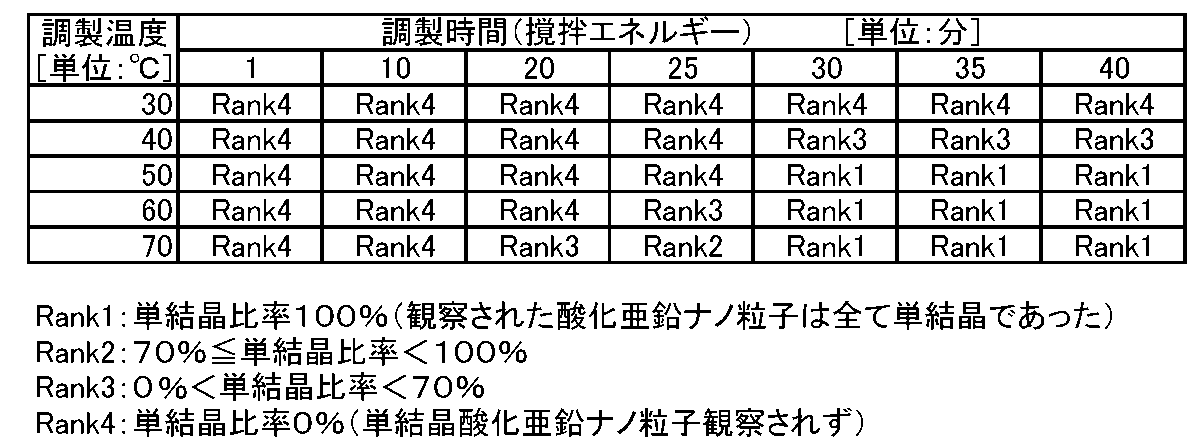
以下に、本願明細書に開示されている発明を付記する。
上記酸化亜鉛析出溶媒が40℃以上で調製されたことを特徴とする、請求項1~16のいずれかに記載の単結晶酸化亜鉛ナノ粒子の製造方法。
上記酸化亜鉛析出溶媒の調製時間を20分以上とすることを特徴とする、請求項1~16のいずれかに記載の単結晶酸化亜鉛ナノ粒子の製造方法。 (Appendix)
The invention disclosed in this specification will be additionally described below.
The method for producing single-crystal zinc oxide nanoparticles according to any one of
The method for producing single-crystal zinc oxide nanoparticles according to any one of
2 第2処理用面
10 第1処理用部
11 第1ホルダ
20 第2処理用部
21 第2ホルダ
d1 第1導入部
d2 第2導入部
d20 開口部 DESCRIPTION OF
Claims (16)
- 酸性物質を少なくともアルコールを含む溶媒に均質に混合させることで酸化亜鉛析出溶媒を調製し、
上記調製した酸化亜鉛析出溶媒と、
酸化亜鉛ナノ粒子原料を塩基性溶媒に混合した原料溶液又は酸化亜鉛ナノ粒子原料を溶媒に混合、溶解することによって結果的に塩基性となる原料溶液とを、
対向して配設された、接近離反可能な相対的に回転する処理用面間で混合させ、
酸化亜鉛ナノ粒子が析出した混合流動体を上記処理用面間から吐出させる酸化亜鉛ナノ粒子の製造方法であって、
上記混合流動体が塩基性となるように、
上記酸化亜鉛析出溶媒と上記原料溶液とを上記処理用面間で混合させ、
上記酸性物質と上記塩基性溶媒の混合による酸塩基反応により、酸化亜鉛ナノ粒子を生成することを特徴とする単結晶酸化亜鉛ナノ粒子の製造方法。 A zinc oxide precipitation solvent is prepared by uniformly mixing an acidic substance with a solvent containing at least an alcohol,
The zinc oxide precipitation solvent prepared above,
A raw material solution in which a zinc oxide nanoparticle raw material is mixed in a basic solvent or a raw material solution that becomes basic by mixing and dissolving the zinc oxide nanoparticle raw material in a solvent,
Mixing between relatively rotating processing surfaces arranged opposite to each other and capable of approaching and separating,
A method for producing zinc oxide nanoparticles, wherein the mixed fluid in which zinc oxide nanoparticles are deposited is discharged from between the processing surfaces,
To make the mixed fluid basic,
The zinc oxide precipitation solvent and the raw material solution are mixed between the processing surfaces,
A method for producing single crystal zinc oxide nanoparticles, wherein zinc oxide nanoparticles are produced by an acid-base reaction by mixing the acidic substance and the basic solvent. - 上記混合流動体のpHが8.6以上14以下であることを特徴する、請求項1に記載の単結晶酸化亜鉛ナノ粒子の製造方法。 The method for producing single crystal zinc oxide nanoparticles according to claim 1, wherein the pH of the mixed fluid is 8.6 or more and 14 or less.
- 上記混合流動体のpHが12以上14以下であることを特徴する、請求項2に記載の単結晶酸化亜鉛ナノ粒子の製造方法。 The method for producing single crystal zinc oxide nanoparticles according to claim 2, wherein the mixed fluid has a pH of 12 or more and 14 or less.
- 上記酸化亜鉛析出溶媒のpHが1未満であり、かつ、上記原料溶液のpHが14を超えることを特徴する、請求項1~3の何れかに記載の単結晶酸化亜鉛ナノ粒子の製造方法。 The method for producing single-crystal zinc oxide nanoparticles according to any one of claims 1 to 3, wherein the zinc oxide precipitation solvent has a pH of less than 1 and the pH of the raw material solution exceeds 14.
- 上記酸性物質が、塩酸、硝酸、硫酸のうち、いずれか1種より選ばれたことを特徴とする、請求項1~4のいずれかに記載の単結晶酸化亜鉛ナノ粒子の製造方法。 The method for producing single-crystal zinc oxide nanoparticles according to any one of claims 1 to 4, wherein the acidic substance is selected from any one of hydrochloric acid, nitric acid, and sulfuric acid.
- 上記アルコールが、メタノール、エタノール、イソプロピルアルコール、tert-ブタノールのうち、いずれか1種より選ばれたことを特徴とする、請求項1~5のいずれかに記載の単結晶酸化亜鉛ナノ粒子の製造方法。 6. The production of single crystal zinc oxide nanoparticles according to claim 1, wherein the alcohol is selected from any one of methanol, ethanol, isopropyl alcohol, and tert-butanol. Method.
- 上記原料溶液が50℃以上で調製されたことを特徴とする、請求項1~6のいずれかに記載の単結晶酸化亜鉛ナノ粒子の製造方法。 The method for producing single crystal zinc oxide nanoparticles according to any one of claims 1 to 6, wherein the raw material solution is prepared at 50 ° C or higher.
- 上記塩基性溶媒は、塩基性水酸化物を溶媒に混合及び/又は溶解したものであることを特徴とする、請求項1~7のいずれかに記載の単結晶酸化亜鉛ナノ粒子の製造方法。 The method for producing single-crystal zinc oxide nanoparticles according to any one of claims 1 to 7, wherein the basic solvent is obtained by mixing and / or dissolving a basic hydroxide in a solvent.
- 上記塩基性水酸化物がアルカリ金属水酸化物であることを特徴とする、請求項8に記載の単結晶酸化亜鉛ナノ粒子の製造方法。 The method for producing single crystal zinc oxide nanoparticles according to claim 8, wherein the basic hydroxide is an alkali metal hydroxide.
- 上記アルカリ金属水酸化物が、水酸化ナトリウム、水酸化カリウム、水酸化リチウムのいずれか1種であることを特徴とする、請求項9に記載の単結晶酸化亜鉛ナノ粒子の製造方法。 The method for producing single crystal zinc oxide nanoparticles according to claim 9, wherein the alkali metal hydroxide is any one of sodium hydroxide, potassium hydroxide, and lithium hydroxide.
- 上記酸化亜鉛ナノ粒子原料が、上記塩基性溶媒に可溶である亜鉛化合物であることを特徴とする、請求項1~10のいずれかに記載の単結晶酸化亜鉛ナノ粒子の製造方法。 The method for producing single-crystal zinc oxide nanoparticles according to any one of claims 1 to 10, wherein the zinc oxide nanoparticle raw material is a zinc compound soluble in the basic solvent.
- 上記亜鉛化合物が、酸化亜鉛、塩化亜鉛、硝酸亜鉛、水酸化亜鉛、硫酸亜鉛のうち、少なくともいずれか1種より選ばれたことを特徴とする、請求項11に記載の単結晶酸化亜鉛ナノ粒子の製造方法。 The single-crystal zinc oxide nanoparticles according to claim 11, wherein the zinc compound is selected from at least one of zinc oxide, zinc chloride, zinc nitrate, zinc hydroxide, and zinc sulfate. Manufacturing method.
- 上記酸化亜鉛析出溶媒と上記原料溶液との何れか一方が、薄膜流体を形成しながら上記処理用面間を通過し、
上記酸化亜鉛析出溶媒と上記原料溶液との何れか他方が、上記酸化亜鉛析出溶媒と上記原料溶液との何れか一方が上記処理用面間に導入される流路とは独立した別途の導入路を経て、上記処理用面の少なくとも何れか一方に形成された開口部から上記処理用面間に導入され、
上記酸化亜鉛析出溶媒と上記原料溶液とが、上記処理用面間で混合されることを特徴とする、請求項1~12のいずれかに記載の単結晶酸化亜鉛ナノ粒子の製造方法。 Either one of the zinc oxide precipitation solvent and the raw material solution passes between the processing surfaces while forming a thin film fluid,
Any one of the zinc oxide precipitation solvent and the raw material solution is a separate introduction path independent of the flow path in which either the zinc oxide precipitation solvent or the raw material solution is introduced between the processing surfaces. Via, is introduced between the processing surfaces from the opening formed in at least one of the processing surfaces,
The method for producing single-crystal zinc oxide nanoparticles according to any one of claims 1 to 12, wherein the zinc oxide precipitation solvent and the raw material solution are mixed between the processing surfaces. - 回転式分散機を用いて上記酸性物質を少なくとも上記アルコールを含む溶媒に均質に混合させるものであり、
上記回転式分散機は、複数の羽根を備えたローターと、上記ローターの周囲に敷設されると共に複数のスリットを有するスクリーンとを備え、上記ローターと上記スクリーンとは、相対的に回転することによって、スリットを含むスクリーンの内壁と羽根との間の微小な間隙において流体のせん断が行われると共に、上記スリットを通じて断続ジェット流としてスクリーンの内側から外側に流体が吐出されるものであることを特徴とする、請求項1~13のいずれかに記載の単結晶酸化亜鉛ナノ粒子の製造方法。 The acidic substance is homogeneously mixed with a solvent containing at least the alcohol using a rotary disperser,
The rotary disperser includes a rotor having a plurality of blades, and a screen laid around the rotor and having a plurality of slits, and the rotor and the screen rotate relative to each other. The fluid is sheared in a minute gap between the inner wall of the screen including the slit and the blade, and the fluid is discharged from the inside to the outside of the screen as an intermittent jet flow through the slit. The method for producing single-crystal zinc oxide nanoparticles according to any one of claims 1 to 13. - 上記酸化亜鉛析出溶媒の調製温度によって、上記生成される酸化亜鉛ナノ粒子の単結晶比率を制御することを特徴とする、請求項1~14のいずれかに記載の単結晶酸化亜鉛ナノ粒子の製造方法。 15. The production of single-crystal zinc oxide nanoparticles according to claim 1, wherein the single-crystal ratio of the zinc oxide nanoparticles produced is controlled by the preparation temperature of the zinc oxide precipitation solvent. Method.
- 上記酸化亜鉛析出溶媒の調製時に投下される撹拌エネルギーによって、上記生成される酸化亜鉛ナノ粒子の単結晶比率を制御することを特徴とする、請求項1~15のいずれかに記載の単結晶酸化亜鉛ナノ粒子の製造方法。 The single crystal oxidation according to any one of claims 1 to 15, wherein the single crystal ratio of the zinc oxide nanoparticles to be produced is controlled by stirring energy dropped during preparation of the zinc oxide precipitation solvent. A method for producing zinc nanoparticles.
Priority Applications (5)
| Application Number | Priority Date | Filing Date | Title |
|---|---|---|---|
| JP2016534437A JP6661083B2 (en) | 2014-07-14 | 2015-07-14 | Method for producing single-crystal zinc oxide nanoparticles |
| US15/320,226 US10364508B2 (en) | 2014-07-14 | 2015-07-14 | Method for producing single crystalline zinc oxide nanoparticles |
| EP15822122.6A EP3170927B1 (en) | 2014-07-14 | 2015-07-14 | Method for preparing single crystal zinc oxide nanoparticles |
| CN201580012139.0A CN106068341B (en) | 2014-07-14 | 2015-07-14 | Method for producing single crystal zinc oxide nanoparticles |
| KR1020167022290A KR102440016B1 (en) | 2014-07-14 | 2015-07-14 | Method for preparing single crystal zinc oxide nanoparticles |
Applications Claiming Priority (2)
| Application Number | Priority Date | Filing Date | Title |
|---|---|---|---|
| JP2014144526 | 2014-07-14 | ||
| JP2014-144526 | 2014-07-14 |
Publications (1)
| Publication Number | Publication Date |
|---|---|
| WO2016010018A1 true WO2016010018A1 (en) | 2016-01-21 |
Family
ID=55078508
Family Applications (1)
| Application Number | Title | Priority Date | Filing Date |
|---|---|---|---|
| PCT/JP2015/070105 WO2016010018A1 (en) | 2014-07-14 | 2015-07-14 | Method for preparing single crystal zinc oxide nanoparticles |
Country Status (6)
| Country | Link |
|---|---|
| US (1) | US10364508B2 (en) |
| EP (1) | EP3170927B1 (en) |
| JP (1) | JP6661083B2 (en) |
| KR (1) | KR102440016B1 (en) |
| CN (1) | CN106068341B (en) |
| WO (1) | WO2016010018A1 (en) |
Cited By (5)
| Publication number | Priority date | Publication date | Assignee | Title |
|---|---|---|---|---|
| WO2017010557A1 (en) * | 2015-07-14 | 2017-01-19 | エム・テクニック株式会社 | Method for producing oxide particles |
| WO2017134910A1 (en) * | 2016-02-02 | 2017-08-10 | エム・テクニック株式会社 | Zinc oxide particles with controlled color properties, method for producing same, and coating composition that includes said zinc oxide particles |
| WO2017209305A1 (en) * | 2016-06-02 | 2017-12-07 | エム・テクニック株式会社 | Oxide particles with controlled color characteristics, and coating composition or film-like composition containing said oxide particles |
| US9949898B2 (en) | 2015-10-05 | 2018-04-24 | M. Technique Co., Ltd. | Silicon oxide-coated iron oxide composition for coating comprising iron oxide particles coated with silicon oxide |
| WO2018150477A1 (en) | 2017-02-14 | 2018-08-23 | エム・テクニック株式会社 | Silicon-doped metal oxide particles, and uv-absorbing composition containing silicon-doped metal oxide particles |
Families Citing this family (4)
| Publication number | Priority date | Publication date | Assignee | Title |
|---|---|---|---|---|
| WO2016152895A1 (en) * | 2015-03-24 | 2016-09-29 | エム・テクニック株式会社 | Stirrer |
| EP3957393A4 (en) * | 2019-04-15 | 2023-07-19 | M. Technique Co., Ltd. | Stirrer |
| CN113060755A (en) * | 2021-03-09 | 2021-07-02 | 安徽景成新材料有限公司 | Preparation method of zinc oxide particles |
| CN114242339B (en) * | 2021-12-24 | 2023-09-22 | 西南科技大学 | Device and method for preparing nano silver wire of front silver paste for solar cell |
Citations (4)
| Publication number | Priority date | Publication date | Assignee | Title |
|---|---|---|---|---|
| JP2009082902A (en) * | 2007-07-06 | 2009-04-23 | M Technique Co Ltd | Nanoparticle production method using forced ultrathin film rotating treatment method |
| WO2012127669A1 (en) * | 2011-03-23 | 2012-09-27 | エム・テクニック株式会社 | Highly efficient method for producing ceramic microparticles |
| WO2012128273A1 (en) * | 2011-03-23 | 2012-09-27 | エム・テクニック株式会社 | Method for producing microparticles |
| WO2013008706A1 (en) * | 2011-07-13 | 2013-01-17 | エム・テクニック株式会社 | Method for manufacturing microparticles with regulated crystallite diameter |
Family Cites Families (12)
| Publication number | Priority date | Publication date | Assignee | Title |
|---|---|---|---|---|
| JP5398126B2 (en) | 2007-06-07 | 2014-01-29 | 第一工業製薬株式会社 | Metal oxide fine particle powder, metal oxide fine particle production method and production system |
| JP4419157B2 (en) | 2007-07-06 | 2010-02-24 | エム・テクニック株式会社 | Production method of fine particles for living ingestion |
| CN102516809B (en) * | 2007-07-06 | 2015-04-01 | M技术株式会社 | Method for producing nanoparticles by forced ultra-thin film rotary processing |
| US8183299B2 (en) | 2007-07-06 | 2012-05-22 | M. Technique Co., Ltd. | Method for producing ceramic nanoparticles |
| JP5131935B2 (en) | 2007-07-06 | 2013-01-30 | エム・テクニック株式会社 | Fluid processing apparatus and processing method |
| JP4359858B2 (en) * | 2007-11-09 | 2009-11-11 | エム・テクニック株式会社 | Method for producing titanium dioxide ultrafine particles |
| JP2010120786A (en) | 2008-11-17 | 2010-06-03 | Tohoku Univ | Oxide hollow particles, production method thereof and apparatus for manufacturing oxide hollow particles |
| US9346685B2 (en) | 2010-05-25 | 2016-05-24 | M. Technique Co., Ltd. | Method for producing substances to be separated having controlled amounts of dopant element |
| WO2012026579A1 (en) | 2010-08-26 | 2012-03-01 | エム・テクニック株式会社 | Method for manufacturing isolatable oxide microparticles or hydroxide microparticles |
| JP2011084465A (en) | 2010-11-30 | 2011-04-28 | Fujifilm Corp | Zinc oxide structure, zinc oxide particle and method for producing the same |
| KR101876767B1 (en) | 2011-03-14 | 2018-07-10 | 엠. 테크닉 가부시키가이샤 | Manufacturing method for metal microparticles |
| KR101954110B1 (en) | 2012-07-13 | 2019-03-05 | 엠. 테크닉 가부시키가이샤 | Stirrer |
-
2015
- 2015-07-14 EP EP15822122.6A patent/EP3170927B1/en active Active
- 2015-07-14 US US15/320,226 patent/US10364508B2/en active Active
- 2015-07-14 KR KR1020167022290A patent/KR102440016B1/en active IP Right Grant
- 2015-07-14 WO PCT/JP2015/070105 patent/WO2016010018A1/en active Application Filing
- 2015-07-14 JP JP2016534437A patent/JP6661083B2/en active Active
- 2015-07-14 CN CN201580012139.0A patent/CN106068341B/en active Active
Patent Citations (4)
| Publication number | Priority date | Publication date | Assignee | Title |
|---|---|---|---|---|
| JP2009082902A (en) * | 2007-07-06 | 2009-04-23 | M Technique Co Ltd | Nanoparticle production method using forced ultrathin film rotating treatment method |
| WO2012127669A1 (en) * | 2011-03-23 | 2012-09-27 | エム・テクニック株式会社 | Highly efficient method for producing ceramic microparticles |
| WO2012128273A1 (en) * | 2011-03-23 | 2012-09-27 | エム・テクニック株式会社 | Method for producing microparticles |
| WO2013008706A1 (en) * | 2011-07-13 | 2013-01-17 | エム・テクニック株式会社 | Method for manufacturing microparticles with regulated crystallite diameter |
Non-Patent Citations (1)
| Title |
|---|
| See also references of EP3170927A4 * |
Cited By (23)
| Publication number | Priority date | Publication date | Assignee | Title |
|---|---|---|---|---|
| WO2017010557A1 (en) * | 2015-07-14 | 2017-01-19 | エム・テクニック株式会社 | Method for producing oxide particles |
| US10196267B2 (en) | 2015-07-14 | 2019-02-05 | M. Technique Co., Ltd. | Method of producing oxide particles |
| US9949898B2 (en) | 2015-10-05 | 2018-04-24 | M. Technique Co., Ltd. | Silicon oxide-coated iron oxide composition for coating comprising iron oxide particles coated with silicon oxide |
| US10182975B2 (en) | 2015-10-05 | 2019-01-22 | M. Technique Co., Ltd. | Silicon oxide-coated iron oxide composition for coating comprising iron oxide particles coated with silicon oxide |
| US11084936B2 (en) | 2016-02-02 | 2021-08-10 | M. Technique Co., Ltd. | Method for producing oxide particles with controlled color characteristics, oxide particles, and coating or film-like composition comprising the same |
| US10400107B2 (en) | 2016-02-02 | 2019-09-03 | M. Technique Co., Ltd. | Method for producing oxide particles with controlled color characteristics, oxide particles, and coating or film-like composition comprising the same |
| JP7461668B2 (en) | 2016-02-02 | 2024-04-04 | エム・テクニック株式会社 | Method for producing oxide particles having controlled color properties, oxide particles, and coating or film-like composition containing the oxide particles |
| JP7155466B2 (en) | 2016-02-02 | 2022-10-19 | エム・テクニック株式会社 | Method for producing oxide particles with controlled color properties, oxide particles, and coating or film-like compositions containing the oxide particles |
| JP2021130607A (en) * | 2016-02-02 | 2021-09-09 | エム・テクニック株式会社 | Method for producing color characteristic-controlled oxide particles, oxide particles, and coating or film composition containing oxide particles |
| WO2017134910A1 (en) * | 2016-02-02 | 2017-08-10 | エム・テクニック株式会社 | Zinc oxide particles with controlled color properties, method for producing same, and coating composition that includes said zinc oxide particles |
| WO2017135393A1 (en) * | 2016-02-02 | 2017-08-10 | エム・テクニック株式会社 | Method for producing color characteristic-controlled oxide particles, oxide particles, and coating or film composition containing said oxide particles |
| US10906097B2 (en) | 2016-06-02 | 2021-02-02 | M. Technique Co., Ltd. | Ultraviolet and/or near-infrared blocking agent composition for transparent material |
| JP6273635B1 (en) * | 2016-06-02 | 2018-02-07 | エム・テクニック株式会社 | Silicon compound-coated oxide particles with controlled color characteristics, and coating or film-like compositions comprising the silicon compound-coated oxide particles |
| US11033960B2 (en) | 2016-06-02 | 2021-06-15 | M. Technique Co., Ltd. | Oxide particles with controlled color characteristics, and coating composition or film-like composition containing said oxide particles |
| WO2017209305A1 (en) * | 2016-06-02 | 2017-12-07 | エム・テクニック株式会社 | Oxide particles with controlled color characteristics, and coating composition or film-like composition containing said oxide particles |
| CN109071255A (en) * | 2016-06-02 | 2018-12-21 | M技术株式会社 | It controls the oxide particle of color characteristics and the coating containing the oxide particle is used or membranaceous composition |
| JP2022031334A (en) * | 2016-06-02 | 2022-02-18 | エム・テクニック株式会社 | Oxide particles with controlled color characteristics, and coating composition or film-like composition containing the oxide particles |
| CN109071255B (en) * | 2016-06-02 | 2022-05-27 | M技术株式会社 | Oxide particles for controlling color characteristics, and coating or film-like composition containing the same |
| JP7421026B2 (en) | 2016-06-02 | 2024-01-24 | エム・テクニック株式会社 | Oxide particles with controlled color properties and coating or film compositions containing the oxide particles |
| WO2017208522A1 (en) | 2016-06-02 | 2017-12-07 | エム・テクニック株式会社 | Ultraviolet and/or near-infrared blocking agent composition for transparent material |
| KR20190119605A (en) | 2017-02-14 | 2019-10-22 | 엠. 테크닉 가부시키가이샤 | A composition for absorbing ultraviolet rays comprising silicon dope metal oxide particles, and silicon dope metal oxide particles |
| WO2018150477A1 (en) | 2017-02-14 | 2018-08-23 | エム・テクニック株式会社 | Silicon-doped metal oxide particles, and uv-absorbing composition containing silicon-doped metal oxide particles |
| US11591239B2 (en) | 2017-02-14 | 2023-02-28 | M. Technique Co., Ltd. | Silicon doped metal oxide particles, and composition for UV absorption comprising silicon doped metal oxide particles |
Also Published As
| Publication number | Publication date |
|---|---|
| US20170130358A1 (en) | 2017-05-11 |
| KR20170031082A (en) | 2017-03-20 |
| EP3170927B1 (en) | 2020-09-30 |
| KR102440016B1 (en) | 2022-09-05 |
| CN106068341B (en) | 2020-06-23 |
| CN106068341A (en) | 2016-11-02 |
| JP6661083B2 (en) | 2020-03-11 |
| EP3170927A4 (en) | 2018-03-14 |
| US10364508B2 (en) | 2019-07-30 |
| EP3170927A1 (en) | 2017-05-24 |
| JPWO2016010018A1 (en) | 2017-06-08 |
Similar Documents
| Publication | Publication Date | Title |
|---|---|---|
| WO2016010018A1 (en) | Method for preparing single crystal zinc oxide nanoparticles | |
| JP5794582B2 (en) | Method for producing separable oxide fine particles or hydroxide fine particles | |
| JP2013082621A5 (en) | ||
| JP6035499B2 (en) | Method for producing fine particles | |
| JP4868558B1 (en) | Method for producing oxide / hydroxide | |
| JP5831821B2 (en) | Method for producing metal fine particles | |
| JP2014023997A (en) | Method for manufacturing particulates | |
| JP5235233B2 (en) | Highly efficient method for producing ceramic fine particles | |
| WO2014041706A1 (en) | Method for manufacturing nickel microparticles | |
| WO2013128592A1 (en) | Microparticle manufacturing method | |
| JP5979645B2 (en) | Method for producing barium titanyl salt and barium titanate | |
| JP2011245474A (en) | Method for producing precipitated substance containing controlled amount of element to be doped therein | |
| JP5376483B1 (en) | Method for producing nickel fine particles | |
| JP4742202B1 (en) | Method for producing precipitated substance with controlled amount of doping element | |
| JP6047833B2 (en) | Garnet precursor fine particles and method for producing fine particles of garnet structure | |
| JP5261780B1 (en) | Method for producing metal fine particles | |
| JP6442715B2 (en) | Method for producing fine particles |
Legal Events
| Date | Code | Title | Description |
|---|---|---|---|
| 121 | Ep: the epo has been informed by wipo that ep was designated in this application |
Ref document number: 15822122 Country of ref document: EP Kind code of ref document: A1 |
|
| ENP | Entry into the national phase |
Ref document number: 20167022290 Country of ref document: KR Kind code of ref document: A |
|
| REEP | Request for entry into the european phase |
Ref document number: 2015822122 Country of ref document: EP |
|
| WWE | Wipo information: entry into national phase |
Ref document number: 2015822122 Country of ref document: EP |
|
| WWE | Wipo information: entry into national phase |
Ref document number: 15320226 Country of ref document: US |
|
| ENP | Entry into the national phase |
Ref document number: 2016534437 Country of ref document: JP Kind code of ref document: A |
|
| NENP | Non-entry into the national phase |
Ref country code: DE |