WO2016010015A1 - 発電機を組み込んだボイラシステム - Google Patents
発電機を組み込んだボイラシステム Download PDFInfo
- Publication number
- WO2016010015A1 WO2016010015A1 PCT/JP2015/070097 JP2015070097W WO2016010015A1 WO 2016010015 A1 WO2016010015 A1 WO 2016010015A1 JP 2015070097 W JP2015070097 W JP 2015070097W WO 2016010015 A1 WO2016010015 A1 WO 2016010015A1
- Authority
- WO
- WIPO (PCT)
- Prior art keywords
- boiler
- stirling engine
- heat
- exhaust
- generator
- Prior art date
- Legal status (The legal status is an assumption and is not a legal conclusion. Google has not performed a legal analysis and makes no representation as to the accuracy of the status listed.)
- Ceased
Links
Images




Classifications
-
- F—MECHANICAL ENGINEERING; LIGHTING; HEATING; WEAPONS; BLASTING
- F02—COMBUSTION ENGINES; HOT-GAS OR COMBUSTION-PRODUCT ENGINE PLANTS
- F02G—HOT GAS OR COMBUSTION-PRODUCT POSITIVE-DISPLACEMENT ENGINE PLANTS; USE OF WASTE HEAT OF COMBUSTION ENGINES; NOT OTHERWISE PROVIDED FOR
- F02G1/00—Hot gas positive-displacement engine plants
- F02G1/04—Hot gas positive-displacement engine plants of closed-cycle type
- F02G1/043—Hot gas positive-displacement engine plants of closed-cycle type the engine being operated by expansion and contraction of a mass of working gas which is heated and cooled in one of a plurality of constantly communicating expansible chambers, e.g. Stirling cycle type engines
-
- F—MECHANICAL ENGINEERING; LIGHTING; HEATING; WEAPONS; BLASTING
- F02—COMBUSTION ENGINES; HOT-GAS OR COMBUSTION-PRODUCT ENGINE PLANTS
- F02G—HOT GAS OR COMBUSTION-PRODUCT POSITIVE-DISPLACEMENT ENGINE PLANTS; USE OF WASTE HEAT OF COMBUSTION ENGINES; NOT OTHERWISE PROVIDED FOR
- F02G5/00—Profiting from waste heat of combustion engines, not otherwise provided for
- F02G5/02—Profiting from waste heat of exhaust gases
-
- F—MECHANICAL ENGINEERING; LIGHTING; HEATING; WEAPONS; BLASTING
- F02—COMBUSTION ENGINES; HOT-GAS OR COMBUSTION-PRODUCT ENGINE PLANTS
- F02G—HOT GAS OR COMBUSTION-PRODUCT POSITIVE-DISPLACEMENT ENGINE PLANTS; USE OF WASTE HEAT OF COMBUSTION ENGINES; NOT OTHERWISE PROVIDED FOR
- F02G5/00—Profiting from waste heat of combustion engines, not otherwise provided for
- F02G5/02—Profiting from waste heat of exhaust gases
- F02G5/04—Profiting from waste heat of exhaust gases in combination with other waste heat from combustion engines
-
- F—MECHANICAL ENGINEERING; LIGHTING; HEATING; WEAPONS; BLASTING
- F22—STEAM GENERATION
- F22B—METHODS OF STEAM GENERATION; STEAM BOILERS
- F22B1/00—Methods of steam generation characterised by form of heating method
- F22B1/02—Methods of steam generation characterised by form of heating method by exploitation of the heat content of hot heat carriers
- F22B1/18—Methods of steam generation characterised by form of heating method by exploitation of the heat content of hot heat carriers the heat carrier being a hot gas, e.g. waste gas such as exhaust gas of internal-combustion engines
-
- F—MECHANICAL ENGINEERING; LIGHTING; HEATING; WEAPONS; BLASTING
- F22—STEAM GENERATION
- F22D—PREHEATING, OR ACCUMULATING PREHEATED, FEED-WATER FOR STEAM GENERATION; FEED-WATER SUPPLY FOR STEAM GENERATION; CONTROLLING WATER LEVEL FOR STEAM GENERATION; AUXILIARY DEVICES FOR PROMOTING WATER CIRCULATION WITHIN STEAM BOILERS
- F22D1/00—Feed-water heaters, i.e. economisers or like preheaters
- F22D1/02—Feed-water heaters, i.e. economisers or like preheaters with water tubes arranged in the boiler furnaces, fire tubes or flue ways
-
- Y—GENERAL TAGGING OF NEW TECHNOLOGICAL DEVELOPMENTS; GENERAL TAGGING OF CROSS-SECTIONAL TECHNOLOGIES SPANNING OVER SEVERAL SECTIONS OF THE IPC; TECHNICAL SUBJECTS COVERED BY FORMER USPC CROSS-REFERENCE ART COLLECTIONS [XRACs] AND DIGESTS
- Y02—TECHNOLOGIES OR APPLICATIONS FOR MITIGATION OR ADAPTATION AGAINST CLIMATE CHANGE
- Y02T—CLIMATE CHANGE MITIGATION TECHNOLOGIES RELATED TO TRANSPORTATION
- Y02T10/00—Road transport of goods or passengers
- Y02T10/10—Internal combustion engine [ICE] based vehicles
- Y02T10/12—Improving ICE efficiencies
Definitions
- This invention relates to a boiler system incorporating a generator driven by a Stirling engine.
- boiler systems have been equipped with auxiliary equipment such as a blower and a feed water pump as utilities for supplying combustion air and boiler feed water.
- auxiliary equipment such as a blower and a feed water pump as utilities for supplying combustion air and boiler feed water.
- Such an auxiliary machine was driven using a commercial power source.
- the steam turbine may be driven by steam generated in the boiler and driven by the power.
- FIG. 1 shows a configuration of a typical conventional boiler system equipped with an auxiliary machine.
- fuel is supplied to a boiler 101 that generates steam, and air for combustion is supplied from a blower 102.
- boiler feed water is supplied from the feed water pump 113 through preheating by the economizer 104.
- Exhaust gas from the boiler 101 is exhausted from an exhaust cylinder 105 through an economizer 104.
- boiler feed water is supplied directly from the feed water pump 113 to the boiler 101, and the exhaust from the boiler 101 is directly discharged from the exhaust pipe 105.
- Stirling engine power generators that generate power from a temperature difference between a high temperature heat source and a low temperature heat source are provided.
- high-temperature heat sources for Stirling engine power generators, one that uses combustion heat obtained by burning fuel with a burner, and another that uses various exhaust heat as a high-temperature heat source.
- Patent Document 1 discloses a technique in which waste heat from a waste incinerator or the like is used as a high-temperature heat source for a Stirling engine.
- the power generation efficiency increases as the temperature difference between the high temperature heat source and the low temperature heat source increases, and heat can be converted into electricity according to the power generation efficiency.
- the remaining heat that has not been converted to electricity is either discarded into the atmosphere or used to heat the water to make hot water.
- Cooling water is used as a low-temperature heat source for the Stirling engine power generator. The cooling water is heated by heat from a high-temperature heat source, but the heat is discarded or used as hot water.
- the Stirling engine power generator alone has a power generation efficiency of less than 40% even when fuel combustion heat is used as a high-temperature heat source, and 60% or more of heat is to be discarded.
- the efficiency of the Stirling engine power generator using exhaust heat was further reduced, and most of the heat was discarded by itself.
- the cooling water of the low-temperature heat source can be used as hot water, or a heat exchanger (recuperator) can be provided to make hot water from the exhaust gas.
- hot water has a limited use compared to steam.
- the present invention is provided in order to solve the above-mentioned problems, and reduces the amount of fuel by improving the overall thermal efficiency of the Stirling engine by combining with a boiler. It aims at providing the boiler system incorporating the generator which reduces the quantity of the electric power supplied from the carbon dioxide to generate
- a boiler system incorporating a generator according to the present invention includes a boiler and a Stirling engine that drives the generator and uses combustion heat as a high-temperature heat source, and the boiler has combustion heat.
- the exhaust heat of the Stirling engine is used as a heat source for generating steam.
- the exhaust heat of the Stirling engine is supplied to the boiler via the economizer, and the boiler is recovered by the economizer in addition to the exhaust heat of the Stirling engine Further, the exhaust heat of the boiler may be included in the heat source for generating steam.
- the first Stirling engine may preheat using boiler feed water supplied to the boiler as a low-temperature heat source, and provide exhaust heat to the boiler by the preheated boiler feed water.
- It may further include a recuperator that recovers exhaust heat from the exhaust of the Stirling engine, and the boiler may also include exhaust heat recovered by the recuperator as a heat source for generating steam.
- the boiler further includes an economizer for recovering exhaust heat from the exhaust of the boiler and a recuperator for recovering exhaust heat from the exhaust of the Stirling engine, wherein the boiler also recovers exhaust heat recovered by the economizer and exhaust heat recovered by the recuperator. It may be included in the heat source of generation.
- It may further include a blower and a water supply pump, and power from the first Stirling engine may be supplied to the blower and the water supply pump.
- a boiler system incorporating the generator according to this application includes a boiler and a Stirling engine that drives the generator and uses the exhaust heat of the boiler as a high-temperature heat source.
- the boiler includes combustion heat and the Stirling engine. Waste heat is used as a heat source for steam generation.
- the heat exchanger may further include a heat exchanger that recovers heat from the exhaust of the boiler, and the exhaust heat of the boiler recovered by the heat exchanger may be supplied to the second Stirling engine as a high-temperature heat source.
- An economizer that provides exhaust heat recovered from the exhaust of the heat exchanger to a heat source for generating steam of the boiler may be further included.
- the second Stirling engine preheats boiler supply water supplied to the boiler as a low-temperature heat source, and provides exhaust heat to the boiler by the preheated boiler supply water.
- the apparatus may further include a blower and a water supply pump, and power from the second Stirling engine may be supplied to the blower and the water supply pump.
- the boiler system incorporating the power generator according to this application drives the boiler, the first power generator that drives the first power generator and uses the combustion heat as a high-temperature heat source, and the second power generator.
- a second Stirling engine that uses exhaust heat of the boiler as a high-temperature heat source, and the boiler uses combustion heat and exhaust heat of the first Stirling engine and the second Stirling engine as a heat source for generating steam.
- the heat exchanger may further include a heat exchanger that recovers heat from the exhaust of the boiler, and the exhaust heat of the boiler recovered by the heat exchanger may be supplied to the second Stirling engine as a high-temperature heat source.
- An economizer that recovers exhaust heat from the exhaust gas of the heat exchanger is further included. Exhaust heat of the first Stirling engine is supplied to the boiler via the economizer or a recuperator, and the boiler is connected to the first Stirling engine. In addition to the exhaust heat, the exhaust heat of the boiler recovered by the economizer is also included in the heat source for generating steam.
- the first Stirling engine and the second Stirling engine preheat using boiler feed water supplied to the boiler as a low-temperature heat source, and provide exhaust heat to the boiler by the preheated boiler feed water.
- the apparatus may further include a blower and a water supply pump, and power from the first Stirling engine and the second Stirling engine may be supplied to the blower and the water supply pump.
- the boiler system incorporating the generator according to this application reduces the amount of fuel by improving the overall thermal efficiency, and consequently reduces the amount of electric power supplied from the outside to the auxiliary equipment of the boiler system and the amount of generated carbon dioxide. Can do.
- FIG. It is a block diagram which shows the schematic structure of the conventional boiler system. It is a block diagram which shows the schematic structure of the boiler system incorporating the generator of Example 1. FIG. It is a block diagram explaining the modification of the boiler system incorporating the generator of Example 1. FIG. It is a block diagram explaining the other modification of the boiler system incorporating the generator of Example 1. FIG. It is a block diagram which shows the schematic structure of the boiler system incorporating the generator of Example 2. FIG. It is a block diagram which shows the schematic structure of the boiler system incorporating the generator of Example 3. FIG. It is a block diagram which shows the schematic structure of the boiler system incorporating the generator of Example 4.
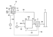
- FIG. 2 is a block diagram showing an overall apparatus of the boiler system incorporating the generator of the first embodiment.
- the boiler system incorporating the generator of Example 1 is a combination of a Stirling engine power generator and a boiler that uses combustion heat obtained by burning fuel with a burner as a high-temperature heat source.
- the boiler system incorporating the generator according to the first embodiment includes the boiler 1, and the boiler city gas 13 ⁇ / b> A is supplied through the flow path 51 at a flow rate of 57.2 m 3 N / h.
- the air used for the combustion is supplied from the blower 2 of the forced-in ventilator through the flow path 52, and the preheated boiler feed water is supplied from the flow path 53.
- the boiler 1 uses the combustion heat of fuel and air as a heat source, and evaporates the preheated boiler feed water into steam.
- the converted evaporation amount of the boiler 1 is 1000 kg / h, and steam having a pressure of 0.7 MPag and a temperature of 170 ° C. is supplied through the flow path 54 at a flow rate of 890 kg / h.
- the boiler system incorporating the generator of the first embodiment includes the first Stirling engine 11, and the city gas 13 ⁇ / b> A as fuel is supplied to the first Stirling engine 11 through the flow path 61.
- Air supplied at a flow rate of 84 m 3 N / h and used for combustion is supplied through the flow path 62, and boiler feed water at 55 ° C. is supplied from the first feed water pump 13 through the flow path 59 to a flow rate of 890 kg / h. Supplied at.
- the first Stirling engine 11 includes a first generator 12, and uses the combustion heat of fuel and air as a high-temperature heat source and pump feed water as cooling water as a low-temperature heat source to drive the first generator 12. .
- the first Stirling engine 11 and the first generator 12 constitute a first Stirling engine power generator 10.
- the first generator 12 supplies 3 kW of power to the blower 2 and the first water supply pump 13 provided in the apparatus via the line 63.
- the first Stirling engine 11 discharges exhaust gas having a temperature of 320 ° C. through the flow path 56 at a flow rate of 15 kg / h, and boiler feed water heated to a temperature of 61 ° C. through the flow path 58 has a flow rate of 890 kg / h. Is discharged.
- the boiler feed water discharged is the boiler feed water having a temperature of 55 ° C. supplied to the first Stirling engine 11 and having a temperature increased by 6 ° C. in the first Stirling engine 11.
- the boiler system incorporating the generator of the first embodiment includes the economizer 4, and boiler water is supplied from the first Stirling engine 11 to the economizer 4 via the flow path 58.
- the exhaust combined with the exhaust of the boiler 1 via the exhaust and the exhaust of the first Stirling engine 11 via the flow path 56 is supplied via the flow path 57 at a flow rate of 1040 kg / h.
- the economizer 4 heats the boiler feed water supplied from the flow path 58 with heat from the exhaust gas supplied from the flow path 57, and supplies the heated boiler feed water to the boiler 1 via the flow path 53.
- the exhaust gas whose heat has been recovered by the economizer 4 is discharged through the flow path 64 and finally discharged into the atmosphere through the exhaust pipe 5.
- the electric power generated by the first Stirling engine power generator 10 including the first Stirling engine 11 and the first generator 12 is used as the blower 2 and the first It supplies to the water supply pump 13.
- the electric power supplied from the first Stirling engine power generator 10 is insufficient, the electric power is supplied from the outside and supplemented.
- the boiler system incorporating the generator according to the first embodiment has a configuration in which the boiler 1 is combined with the first Stirling engine power generator 10 that uses combustion heat as a high-temperature heat source, and low-temperature boiler feed water is supplied to the first Stirling engine.
- the first Stirling engine power generator 10 that uses combustion heat as a high-temperature heat source
- low-temperature boiler feed water is supplied to the first Stirling engine.
- the fuel consumption is reduced by utilizing it for evaporation or preheating of boiler feed water.
- the electric power obtained by the first Stirling engine power generator 10 is supplied to the motor of the auxiliary machine of the boiler 1 such as the blower 2 and the first water supply pump 13, so that the external power consumed by the auxiliary machine of the boiler 1 is consumed. The amount of power supplied is reduced.
- Table 1 shows the results of calculating various quantities when the boiler system incorporating the generator of Example 1 is operated in comparison with the conventional example shown in FIG.
- SE means the first Stirling engine power generator 10.
- Example 1 the system members corresponding to Example 1 and the conventional example have the same configuration, and operate under common conditions.
- a boiler 101 having a converted evaporation amount of 1000 kg / h is supplied with fuel city gas 13A at a flow rate of 57.7 m 3 N / h, steam at a pressure of 0.7 MPag and a temperature of 170 ° C. Is generated at a flow rate of 890 kg / h, exhaust is discharged at a flow rate of 1040 kg / h, and the exhaust gas is cooled to a temperature of 125 ° C. by an economizer 104 to which boiler feed water at a flow rate of 890 kg / h is supplied at a temperature of 55 ° C.
- economizer 104 to which boiler feed water at a flow rate of 890 kg / h is supplied at a temperature of 55 ° C.
- Example 1 the total fuel consumption of the boiler 1 and the first Stirling engine 11 is increased, while the power (amount of power purchased) supplied from the outside to the auxiliary equipment (utility) is Has been reduced. In addition to the operating cost of adding fuel and electricity, the amount of carbon dioxide (CO 2 ) generated from fuel and externally supplied power is reduced.
- CO 2 carbon dioxide
- FIG. 3 is a view showing a modification of the boiler system in which the generator of the first embodiment is incorporated.
- a recuperator 14 is provided in the rear stage of the first Stirling engine 11 of the first Stirling engine power generator 10 in the first embodiment shown in FIG.
- Exhaust gas from the high-temperature heat source from the first Stirling engine 11 is exhausted by the recuperator 14 and then exhausted to the channel 64 via the channel 56.
- Boiler feed water preheated by the first Stirling engine 11 is supplied to the recuperator 14 via the flow path 66, further preheated by the exhaust of the high temperature heat source, and supplied to the economizer 4 via the flow path 58.
- the boiler 1 further includes the exhaust heat of the boiler 1 recovered by the economizer 4 and the exhaust heat of the exhaust of the first Stirling engine 11 recovered by the recuperator 14 as a heat source for generating steam. Therefore, the overall thermal efficiency is further improved.
- the economizer 4 may be omitted.
- the boiler feed water preheated by the first Stirling engine 11 and the recuperator 14 is directly supplied to the boiler 1 via the flow path 58.
- Exhaust gas from the boiler 1 is directly discharged from the exhaust cylinder 5.
- the boiler 1 further includes the exhaust heat of the exhaust gas from the first Stirling engine 11 collected by the recuperator 14 as a heat source for generating steam, so that the overall thermal efficiency is improved.
- FIG. 4 is a view showing another modification of the boiler system incorporating the generator of the first embodiment. This modification is different from the boiler feed water flow path 58 discharged from the first Stirling engine 11 in the configuration of the first embodiment shown in FIG. 1 from the first feed water pump 13 to the first Stirling engine 11.
- a circulation pump 15 that recirculates a part of boiler feed water toward a flow path 59 for supplying feed water is provided.
- This modification is useful for securing the cooling water amount when the boiler water supply to the boiler 1 decreases when the load on the boiler 1 is reduced and falls below the water supply amount required by the first Stirling engine 11.
- a flow path 60 directed from the boiler feed water flow path 58 discharged from the first Stirling engine 11 toward the suction side of the first feed water pump 13 is provided to recirculate a part of the boiler feed water. You may let them. In addition, you may abbreviate
- FIG. 5 is a block diagram showing an overall apparatus of the boiler system incorporating the generator of the second embodiment.
- the boiler system incorporating the generator of the second embodiment is a combination of a boiler and a Stirling engine power generator that uses exhaust heat as a high-temperature heat source.
- the boiler system incorporating the generator according to the second embodiment includes the boiler 1, and fuel gas 13 ⁇ / b> A is supplied to the boiler 1 through the flow path 51 at a flow rate of 57.0 m 3 N / h.
- the air used for combustion is supplied from the blower 2 of the forced-in ventilator through the flow path 52, and the preheated boiler feed water is supplied from the flow path 58 at a flow rate of 890 kg / h.
- the boiler 1 uses the combustion heat of fuel and air as a heat source, and evaporates the preheated boiler feed water into steam.
- the converted evaporation amount of the boiler 1 is 1000 kg / h, and steam having a pressure of 0.7 MPag and a temperature of 170 ° C. is supplied through the flow path 54 at a flow rate of 890 kg / h.
- the boiler system incorporating the generator of the second embodiment includes the second Stirling engine 21, and hot water is supplied to the second Stirling engine 21 via the flow path 71, and the temperature is 55 ° C.
- the boiler feed water is supplied from the second feed water pump 23 through the flow path 75.
- the second Stirling engine 21 includes a second generator 22, and drives the second generator 22 by using a high-temperature heat medium as a high-temperature heat source and using boiler feed water as cooling water as a low-temperature heat source.
- the second Stirling engine 21 and the second generator 22 constitute a second Stirling engine power generator 20.
- the second generator 22 supplies 1 kW of power to the blower 2 and the second water supply pump 23 provided in the apparatus via a line 76.
- the second Stirling engine 21 discharges the heat medium supplied from the flow path 71 and used as a high-temperature heat source to the flow path 72. Further, boiler feed water supplied from the flow path 75 and used as a low-temperature heat source is discharged to the flow path 74.
- the boiler feed water discharged is a boiler feed water having a temperature of 55 ° C. supplied to the second Stirling engine 21 that has absorbed the heat in the second Stirling engine 21 and raised the temperature to 61 ° C.
- the boiler system incorporating the generator of the second embodiment includes the heat exchanger 3, and the heat medium of the high-temperature heat source of the second Stirling engine 21 is passed through the flow path 72 in the heat exchanger 3.
- the exhaust gas having a temperature of 240 ° C. of the boiler 1 is supplied through the flow path 55.
- the heat exchanger 3 transfers heat from the exhaust gas supplied from the flow channel 55 to the heat medium supplied from the flow channel 72, and supplies the heated heat medium to the second Stirling engine 21 via the flow channel 71.
- the exhaust gas having a temperature of 220 ° C. is discharged through the flow path 73 at a flow rate of 1030 kg / h.
- the boiler system incorporating the generator of the second embodiment includes an economizer 4, and boiler water is supplied from the second Stirling engine 21 to the economizer 4 via the flow path 74, and the heat exchanger 3 exhaust gas of 220 ° C. is supplied through the flow path 73 at a flow rate of 1030 kg / h.
- the economizer 4 heats the boiler feed water supplied from the flow path 74 with heat recovered from the exhaust gas supplied from the flow path 73, and supplies the heated boiler feed water to the boiler 1 via the flow path 58.
- the exhaust gas whose heat has been recovered by the economizer 4 is discharged through the flow path 64 and finally discharged into the atmosphere through the exhaust pipe 5.
- the electric power generated by the second Stirling engine power generator 20 including the second Stirling engine 21 and the second generator 22 is used as the blower 2 and the second power generator. It supplies to the water supply pump 23.
- the electric power supplied from the second Stirling engine power generator 20 is insufficient, the electric power is supplied from the outside and supplemented.
- the boiler system incorporating the generator according to the second embodiment is configured by combining the boiler 1 with the second Stirling engine power generator 20 that uses the exhaust heat of the boiler as a high-temperature heat source, and using low-temperature boiler feed water as a low-temperature heat source.
- the fuel consumption of the boiler necessary to obtain the same amount of evaporation is reduced compared to a boiler-only system.
- Table 2 shows the results of calculating various quantities when the boiler incorporating the generator of Example 2 is operated in comparison with the conventional example shown in FIG. In this comparison, it is assumed that the system configuration, operation conditions, and the like in Example 2 and the conventional example are common.
- SE means the second Stirling engine power generator 20.
- the total fuel consumption of the boiler 1 and the second Stirling engine 21 is reduced, and the power (amount of electricity purchased) supplied to the auxiliary equipment (utility) from the outside is also reduced. Yes.
- the amount of carbon dioxide (CO 2 ) generated from fuel and external power is also reduced.
- the boiler feed water flow path 74 discharged from the low temperature heat source of the second Stirling engine 21 A part of the boiler feed water may be recirculated by a circulation pump toward the flow path 75 for supplying the boiler feed water from the feed water pump 23 to the second Stirling engine 21.
- a flow path may be provided on the suction side of the second feed water pump 23 from the flow path 74 of the boiler feed water discharged from the low temperature heat source to recirculate part of the boiler feed water.
- FIG. 6 is a block diagram showing an overall apparatus of the boiler system incorporating the generator of the third embodiment.
- the boiler system incorporating the generator of Example 3 is a combination of both a Stirling engine power generator using combustion heat as a high-temperature heat source and a Stirling engine power generator using exhaust heat as a high-temperature heat source in combination with the boiler.
- the boiler system incorporating the generator according to the third embodiment includes the boiler 1.
- the boiler 1 is supplied with the fuel city gas 13 ⁇ / b> A through the flow path 51, and the air used for combustion is pushed in.
- the boiler feed water supplied from the blower 2 through the flow path 52 and preheated is supplied from the flow path 53.
- the boiler 1 uses the combustion heat of fuel and air as a heat source, and evaporates the preheated boiler feed water into steam.
- the converted evaporation amount of the boiler 1 is 1000 kg / h, and steam having a pressure of 0.7 MPag and a temperature of 170 ° C. is supplied through the flow path 54 at a flow rate of 890 kg / h.
- the boiler system incorporating the generator of the third embodiment includes the first Stirling engine 11, and fuel gas 13 ⁇ / b> A is supplied to the first Stirling engine 11 through the flow path 61. Air used for combustion is supplied via the flow path 62, and boiler feed water used for cooling water is supplied via the flow path 81.
- the first Stirling engine 11 includes a first generator 12, and uses the combustion heat of fuel and air as a high-temperature heat source and boiler feed water as cooling water as a low-temperature heat source to drive the first generator 12. .
- the first Stirling engine 11 and the first generator 12 constitute a first Stirling engine power generator 10.
- the first generator 12 supplies 3 kW of power to the blower 2 and the second water supply pump 23 via the line 63.
- the first Stirling engine 11 discharges the exhaust through the flow path 56 and discharges the heated boiler feed water through the flow path 58.
- the boiler system incorporating the generator of the third embodiment includes the second Stirling engine 21, and a high-temperature heat medium is supplied to the second Stirling engine 21 via the flow path 71.
- Boiler feed water is supplied from the second feed water pump 23 via the flow path 75.
- the second Stirling engine 21 includes a second generator 22, and drives the second generator 22 by using a high-temperature heat medium as a high-temperature heat source and using boiler feed water as cooling water as a low-temperature heat source.
- the second Stirling engine 21 and the second generator 22 constitute a second Stirling engine power generator 20.
- the second generator 22 supplies 1 kW of power to the blower 2 and the second water supply pump 23 provided in the apparatus via a line 76.
- the second Stirling engine 21 discharges the heat medium supplied from the flow path 71 and used as a high-temperature heat source to the flow path 72.
- boiler feed water supplied from the flow path 75 and used as a low-temperature heat source is discharged to the flow path 81.
- the boiler system incorporating the generator of the third embodiment includes the heat exchanger 3, and the heat medium of the high-temperature heat source of the second Stirling engine 21 is passed through the flow path 72 in the heat exchanger 3.
- Exhaust gas which is a combination of the exhaust gas from the boiler 1 via the flow channel 55 and the exhaust gas from the first Stirling engine 11 via the flow channel 56, is supplied via the flow channel 57.
- the heat exchanger 3 moves heat from the exhaust gas supplied from the flow path 57 to the heat medium supplied from the flow path 72, and supplies the heated heat medium to the second Stirling engine 21 via the flow path 71.
- the exhaust is discharged through the flow path 73.
- the boiler system incorporating the generator of the third embodiment includes the economizer 4, and the boiler water supplied from the first Stirling engine 11 is supplied to the economizer 4 through the flow path 58.
- Exhaust gas from the heat exchanger 3 is supplied via a flow path 73.
- the economizer 4 heats the boiler feed water supplied from the flow path 58 with the heat recovered from the exhaust gas supplied from the flow path 73, and supplies the heated boiler feed water to the boiler 1 via the flow path 53.
- the exhaust gas whose heat has been recovered by the economizer 4 is discharged through the flow path 64 and finally discharged into the atmosphere through the exhaust pipe 5.
- not only the economizer 4 but also a recuperator can be used.
- the electric power generated by the first Stirling engine power generator 10 and the second Stirling engine power generator 20 is supplied to the blower 2 and the second water supply pump 23. is doing.
- the power supplied from the first Stirling engine power generator 10 and the second Stirling engine power generator 20 is insufficient, the power is supplied from the outside and supplemented.
- both the first Stirling engine power generator 10 using combustion heat as a high-temperature heat source and the second Stirling engine power generator 20 using exhaust heat as a high-temperature heat source are used as the boiler 1.
- the low temperature boiler water supply is used as a low temperature heat source for the second Stirling engine power generation device 20 and the first Stirling engine power generation device 10, thereby securing a low temperature heat source and using the waste heat of the low temperature heat source to supply boiler water
- the boiler fuel consumption required to obtain the same amount of evaporation is reduced compared to a boiler-only system.
- the exhaust heat from the boiler 1 is used as a high-temperature heat source for temperature difference power generation of the second Stirling engine power generator 20, and this electric power is supplied to the motors of auxiliary equipment of the boiler 1 system such as the blower 2 and the second water supply pump 23. By doing so, the amount of power consumed by the auxiliary machine of the boiler system is reduced.
- Table 3 shows the results of calculating various quantities when operating the boiler system incorporating the generator of Example 3 in comparison with the conventional example shown in FIG. In this comparison, it is assumed that the system configuration, operation conditions, and the like in Example 3 and the conventional example are common. Note that “SE” in the table means the first Stirling engine power generator 10 and the second Stirling engine power generator 20.
- Example 3 the total fuel consumption of the boiler 1, the first Stirling engine 11, and the second Stirling engine 21, as well as the electric power (utility) supplied from the outside (utility) The amount of electricity purchased) has also been reduced. In addition to the operating cost of adding fuel and electricity, the amount of carbon dioxide (CO 2 ) generated from fuel and external power is also reduced.
- CO 2 carbon dioxide
- the economizer 4 can be omitted.
- boiler feed water discharged from the low-temperature heat source of the first Stirling engine is supplied from the flow path 58 to the boiler 1 via the flow path 53 without passing through the economizer 4.
- the exhaust gas of the boiler 1 from the heat exchanger 3 is sent to the exhaust pipe 5 through the flow path 64 without passing through the economizer 4.
- the recuperator 14 is provided in the first Stirling engine power generation apparatus 10 as in the modification of the first embodiment, and heat is recovered from the exhaust gas of the high-temperature heat source to supply the boiler feed water. You may heat.
- the boiler feed water is supplied from the second Stirling engine 21 to the first Stirling engine 11 from the boiler feed water flow path 58 discharged from the first Stirling engine 11.
- a circulation pump that recirculates part of the boiler feed water toward the flow path 81 may be provided.
- a part of boiler feed water may be refluxed.
- a flow path from the boiler feed water flow path 81 discharged from the second Stirling engine 21 toward the suction side of the second feed water pump 23 is provided to recirculate part of the boiler feed water. May be.
- FIG. 7 is a block diagram showing an overall apparatus of the boiler system incorporating the generator of the fourth embodiment.
- the cooling water can be continuously supplied to the first Stirling engine power generator 10 in the configuration of the boiler system incorporating the generator of the first embodiment.
- a buffer tank 91 is further provided.
- Other configurations are the same as those of the boiler system incorporating the generator of the first embodiment.
- the buffer tank 91 is a container having a predetermined capacity, and is configured to store up to a predetermined amount of water 111 therein.
- the buffer tank 91 is provided with a water level meter 97 that can detect the water level of the internal water 111.
- a water level meter 97 that can detect the water level of the internal water 111.
- FIG. 7 an electrode rod type water level gauge 97 is shown, but the present invention is not limited to this, and other types of water level gauges can be used.
- the buffer tank 91 is supplied with water from a water supply source (not shown) via a flow path 92.
- a valve is provided in the flow path 92, and the valve is opened / closed based on the water level detected by the water level gauge 97, and the water level of the water 111 in the buffer tank 91 is controlled to be within a predetermined range. .
- the stored water is supplied as cooling water to the first Stirling engine 11 via the flow path 59 by the first water supply pump 13.
- the cooling water is discharged after being used as a low-temperature heat source of the first Stirling engine 11, and is returned to the buffer tank 91 via the flow path 93.
- the stored water is supplied from the buffer tank 91 to the boiler feed water through the economizer 4 through the flow path 58 by the third feed pump 95.
- the cooling water is continuously circulated by the closed circulation line through the flow paths 59 and 93 between the buffer tank 91 and the first Stirling engine 11.
- boiler water supplied to the economizer 4 is sent from the buffer tank 91 through a flow path 58 different from the circulation line.
- the boiler feed water is intermittently performed depending on the water level in the boiler 1, so that the third feed pump 95 may be repeatedly operated and stopped.
- the first Stirling engine 11 can be continuously operated by continuously supplying the cooling water through the circulation line. Therefore, even when the pump water supply is intermittently performed, it is ensured that the power generation efficiency and the internal temperature of the first Stirling engine 11 are maintained.
- the cooling water continues to circulate through the circulation line, and the temperature of the water 111 stored in the buffer tank 91 may gradually increase.
- the load of the first Stirling engine 11 is reduced, and further, the first Stirling engine 11 can be stopped when the water stored in the buffer tank 91 rises to a predetermined temperature.
- the air blower 2 and the 2nd water supply pump 23 were illustrated as an auxiliary machine, this invention is not restricted to these, It can apply to a desired auxiliary machine. Moreover, it can replace with the 1st Stirling engine 11 and the 2nd Stirling engine 21 which were illustrated in this Embodiment, and a thermoacoustic electric power generating apparatus can also be utilized. Furthermore, in the present embodiment, the city gas 13A is used as the fuel. However, the present invention is not limited to this, as long as it can obtain the heat of combustion, and may be, for example, garbage or petroleum.
Landscapes
- Engineering & Computer Science (AREA)
- Mechanical Engineering (AREA)
- General Engineering & Computer Science (AREA)
- Chemical & Material Sciences (AREA)
- Combustion & Propulsion (AREA)
- Physics & Mathematics (AREA)
- Thermal Sciences (AREA)
- Life Sciences & Earth Sciences (AREA)
- Sustainable Development (AREA)
- Sustainable Energy (AREA)
- Control Of Steam Boilers And Waste-Gas Boilers (AREA)
Abstract
ボイラ(1)と、第1の発電機(12)を駆動し、燃焼熱を高温熱源とする第1のスターリングエンジン(11)と、ボイラ(1)の排気から排熱を回収するエコノマイザ(4)と、送風機(2)及び第1の給水ポンプ(13)とを含み、第1のスターリングエンジン(11)では低温熱源として供給されたボイラ給水が予熱され、第1のスターリングエンジン(11)の排熱はボイラ(1)に供給され、ボイラ(1)は第1のスターリングエンジン(11)の排熱に加えてエコノマイザ(4)で回収されたボイラ(1)の排熱も蒸気発生の熱源に含み、第1のスターリングエンジン(11)からの電力は送風機(2)及び第1の給水ポンプ(13)に供給され、ボイラシステムのエネルギー効率を向上させる。
Description
この発明は、スターリングエンジンにより駆動される発電機を組み込んだボイラシステムに関する。
従来、ボイラシステムには、燃焼用の空気やボイラ給水を供給するユーティリティとして送風機や給水ポンプなどの補機が備えられている。このような補機は、商用電源を用いて駆動されていた。あるいは、ボイラで発生した蒸気で蒸気タービンを駆動し、その動力で駆動することもあった。
図1は、補機を備える従来の典型的なボイラシステムの構成を示している。このシステムにおいて、蒸気を発生するボイラ101には、燃料が供給されるとともに、送風機102から燃焼のための空気が供給されている。また、給水ポンプ113からボイラ給水がエコノマイザ104による予熱を経て供給されている。ボイラ101の排気はエコノマイザ104を経て排気筒105から排出されている。エコノマイザ104が設置されない場合は、ボイラ給水は給水ポンプ113から直接ボイラ101に供給され、ボイラ101の排気は直接排気筒105から排出される。
一方、高温熱源と低温熱源との温度差から電力を発生するスターリングエンジン発電装置が提供されている。スターリングエンジン発電装置の高温熱源には、燃料をバーナで燃焼させた燃焼熱を利用するものと、種々の排熱を高温熱源として利用するものとがある。特許文献1には、ごみ焼却炉等の排熱をスターリングエンジンの高温熱源とする技術が開示されている。
スターリングエンジン発電装置においては、高温熱源と低温熱源の温度差が大きいほど発電効率も高く、発電効率に応じて熱を電気に変換することができる。電気に変換されなかった残りの熱は大気に捨てられるか、あるいは水を加熱して温水を作るのに利用される。スターリングエンジン発電装置の低温熱源には冷却水が使用される。冷却水は高温熱源からの熱で加熱されるが、その熱は捨てられるか、あるいは温水として利用される。
ボイラシステムの補機を商用電源から供給された電力を用いてモータ駆動する場合、ランニングコストとして電気代が必要となっていた。発電所の送電端効率は40%未満であり、その価格は高いものとなっている。一方、補機を蒸気タービンの動力で駆動する場合、ボイラシステムから供給できる蒸気量が減少する。
一方、スターリングエンジン発電装置は、単体では燃料の燃焼熱を高温熱源とする場合でも発電効率は40%未満であり、60%以上の熱を捨てることになっていた。排熱利用のスターリングエンジン発電装置ではさらに効率が低下し、単体ではほとんどの熱を捨てることになっていた。また、高温熱源及び低温熱源の排熱を有効利用するために、低温熱源の冷却水を温水として利用したり、熱交換器(レキュペレータ)を設けて排ガスから温水を作り利用したりすることができるが、温水は蒸気と比べ利用先が限られていた。
この発明は、上述の課題を解決するために提供されるものであって、ボイラとの組み合わせによりスターリングエンジンの総合熱効率を向上させることにより燃料の量を削減し、ひいてはボイラシステムの補機に外部から供給する電力、発生する二酸化炭素の量を低減するような発電機を組み込んだボイラシステムを提供することを目的とする。
上述の課題を解決するために、この発明に係る発電機を組み込んだボイラシステムは、ボイラと、発電機を駆動し、燃焼熱を高温熱源とするスターリングエンジンとを含み、前記ボイラは燃焼熱とともに前記スターリングエンジンの排熱を蒸気発生の熱源とする。
前記ボイラの排気から排熱を回収するエコノマイザをさらに含み、前記スターリングエンジンの排熱は前記エコノマイザを介して前記ボイラに供給され、前記ボイラは前記スターリングエンジンの排熱に加えて前記エコノマイザで回収された前記ボイラの排熱も蒸気発生の熱源に含んでもよい。前記第1のスターリングエンジンは、前記ボイラに供給されるボイラ給水を低温熱源として使用して予熱し、この予熱されたボイラ給水により前記ボイラに排熱を提供してもよい。
前記スターリングエンジンの排気から排熱を回収するレキュペレータをさらに含み、前記ボイラは前記レキュペレータで回収された排熱も蒸気発生の熱源に含んでもよい。
前記ボイラの排気から排熱を回収するエコノマイザ及び前記スターリングエンジンの排気から排熱を回収するレキュペレータをさらに含み、前記ボイラは前記エコノマイザで回収された排熱及び前記レキュペレータで回収された排熱も蒸気発生の熱源に含んでもよい。
送風機及び給水ポンプをさらに含み、前記第1のスターリングエンジンからの電力は前記送風機及び前記給水ポンプに供給されてもよい。
また、この出願に係る発電機を組み込んだボイラシステムは、ボイラと、発電機を駆動し、前記ボイラの排熱を高温熱源とするスターリングエンジンとを含み、前記ボイラは燃焼熱及び前記スターリングエンジンの排熱を蒸気発生の熱源とする。
前記ボイラの排気から熱を回収する熱交換器をさらに含み、前記第2のスターリングエンジンには前記熱交換器で回収された前記ボイラの排熱が高温熱源として供給されてもよい。前記熱交換器の排気から回収した排熱を前記ボイラの蒸気発生の熱源に提供するエコノマイザをさらに含んでもよい。
前記第2のスターリングエンジンは、前記ボイラに供給されるボイラ給水を低温熱源として使用して予熱し、この予熱されたボイラ給水により前記ボイラに排熱を提供する。送風機及び給水ポンプをさらに含み、前記第2のスターリングエンジンからの電力は前記送風機及び前記給水ポンプに供給されてもよい。
さらに、この出願に係る発電機を組み込んだボイラシステムは、ボイラと、第1の発電機を駆動し、燃焼熱を高温熱源とする第1のスターリングエンジンと、第2の発電機を駆動し、前記ボイラの排熱を高温熱源とする第2のスターリングエンジンとを含み、前記ボイラは燃焼熱とともに前記第1のスターリングエンジン及び前記第2のスターリングエンジンの排熱を蒸気発生の熱源とする。
前記ボイラの排気から熱を回収する熱交換器をさらに含み、前記第2のスターリングエンジンには前記熱交換器で回収された前記ボイラの排熱が高温熱源として供給されてもよい。前記熱交換器の排気から排熱を回収するエコノマイザをさらに含み、前記第1のスターリングエンジンの排熱は前記エコノマイザまたはレキュペレータを介して前記ボイラに供給され、前記ボイラは前記第1のスターリングエンジンの排熱に加えて前記エコノマイザで回収された前記ボイラの排熱も蒸気発生の熱源に含む。
前記第1のスターリングエンジン及び前記第2のスターリングエンジンは、前記ボイラに供給されるボイラ給水を低温熱源として使用して予熱し、この予熱されたボイラ給水により前記ボイラに排熱を提供する。送風機及び給水ポンプをさらに含み、前記第1のスターリングエンジン及び前記第2のスターリングエンジンからの電力は前記送風機及び前記給水ポンプに供給されてもよい。
この出願に係る発電機を組み込んだボイラシステムは、総合熱効率を向上させることにより燃料の量を削減し、ひいてはボイラシステムの補機に外部から供給する電力、発生する二酸化炭素の量を低減することができる。
以下、発電機を込みこんだボイラシステムの実施の形態について図面を参照して詳細に説明する。なお、以下の実施例は、本実施の形態を示すために例示するものであり、本発明を限定するものではない。また、実施例中の各種数値、燃料の種類、補機の種類等は説明のために示すものであり、本発明はこれらに限らず実施することができる。
図2は、実施例1の発電機を組み込んだボイラシステムの全体の装置を示すブロック図である。実施例1の発電機を組み込んだボイラシステムは、燃料をバーナで燃焼させた燃焼熱を高温熱源とするスターリングエンジン発電装置とボイラを組合せたものである。
実施例1の発電機を組み込んだボイラシステムには、ボイラ1が含まれ、このボイラ1には、燃料の都市ガス13Aが流路51を介して57.2m3N/hの流量で供給され、燃焼に用いられる空気が押し込み通風機の送風機2から流路52を介して供給され、予熱されたボイラ給水が流路53から供給されている。ボイラ1は、燃料と空気の燃焼熱を熱源とし、予熱されたボイラ給水を蒸発させて蒸気にしている。ボイラ1の換算蒸発量は1000kg/hであり、圧力0.7MPagで温度170℃の蒸気を流路54を介して890kg/hの流量で供給している。
また、実施例1の発電機を組み込んだボイラシステムには、第1のスターリングエンジン11が含まれ、この第1のスターリングエンジン11には、燃料の都市ガス13Aが流路61を介して0.84m3N/hの流量で供給され、燃焼に用いられる空気が流路62を介して供給され、55℃のボイラ給水が第1の給水ポンプ13から流路59を介して890kg/hの流量で供給されている。
第1のスターリングエンジン11は、第1の発電機12を備え、燃料と空気の燃焼熱を高温熱源とし、ポンプ給水を冷却水として低温熱源に用い、第1の発電機12を駆動している。これら第1のスターリングエンジン11と第1の発電機12とは、第1のスターリングエンジン発電装置10を構成している。
第1の発電機12は、3kWの電力を線路63を介してこの装置に備えられる送風機2と第1の給水ポンプ13とに供給している。第1のスターリングエンジン11は、温度320℃の排気を流路56を介して15kg/hの流量で排出し、温度61℃に昇温したボイラ給水を流路58を介して890kg/hの流量で排出している。排出されるボイラ給水は、第1のスターリングエンジン11に供給された温度55℃のボイラ給水が、第1のスターリングエンジン11において温度が6℃上昇したものである。
さらに、実施例1の発電機を組み込んだボイラシステムには、エコノマイザ4が含まれ、このエコノマイザ4には、ボイラ給水が第1のスターリングエンジン11から流路58を介して供給され、流路55を介したボイラ1の排気と流路56を介した第1のスターリングエンジン11の排気とを併せた排気が流路57を介して1040kg/hの流量で供給されている。エコノマイザ4は、流路57から供給された排気からの熱で流路58から供給されたボイラ給水を加熱し、昇温したボイラ給水を流路53を介してボイラ1に供給している。エコノマイザ4で熱を回収された排気は、流路64を介して排出され、最終的に排気筒5を介して大気中に排出される。
この実施例1の発電機を組み込んだボイラシステムにおいては、第1のスターリングエンジン11と第1の発電機12とを含む第1のスターリングエンジン発電装置10で発電した電力を送風機2と第1の給水ポンプ13とに供給している。この第1のスターリングエンジン発電装置10から供給される電力が不足する場合には、外部から電力を供給して補充する。
この実施例1の発電機を組み込んだボイラシステムは、燃焼熱を高温熱源とする第1のスターリングエンジン発電装置10とボイラ1を組合せた構成を有し、低温のボイラ給水を第1のスターリングエンジン11の低温熱源として使用することにより、低温熱源を確保し、かつ低温熱源からの排熱でボイラ給水を予熱することで、ボイラ単独のシステムと比べ、同じ蒸発量を得るのに必要なボイラの燃料消費量を削減している。
また、第1のスターリングエンジン11の高温熱源の排熱をボイラ1またはエコノマイザ4の入口に導入することにより、ボイラ給水の蒸発あるいは予熱に活用することにより燃料消費量を削減している。さらに、第1のスターリングエンジン発電装置10で得られた電力は、送風機2、第1の給水ポンプ13等のボイラ1の補機のモータに供給することにより、ボイラ1の補機で消費する外部供給の電力量を削減している。
ここで、実施例1の発電機を組み込んだボイラシステムを運転したときの諸量を図1に示した従来例と比較して算出した結果を表1に示す。なお、表における「SE」は第1のスターリングエンジン発電装置10を意味している。
この比較において、実施例1と従来例とにおいて対応するシステムの部材は同様の構成を有し、共通の条件で運転するものとする。例えば、図1の従来例において、換算蒸発量1000kg/hを有するボイラ101には燃料の都市ガス13Aが57.7m3N/hの流量で供給され、圧力0.7MPagで温度170℃の蒸気が890kg/hの流量で発生し、1040kg/hの流量で排気が排出され、温度55℃で流量890kg/hのボイラ給水が供給されるエコノマイザ104でこの排気が温度125℃まで冷却されるものとする。

表1に示された結果を参照すると、実施例1においてはボイラ1と第1のスターリングエンジン11の合計の燃費が増加する一方、外部から補機(ユーティリティ)に供給する電力(買電量)は削減されている。また、燃料代と電気代を合計した運転費用とともに、燃料と外部から供給した電力に由来する二酸化炭素(CO2)発生量が削減されている。
図3は、実施例1の発電機を組み込んだボイラシステムの変形例を示す図である。この変形例は、図1に示した実施例1において、第1のスターリングエンジン発電装置10の第1のスターリングエンジン11の後段にレキュペレータ14を設けたものである。第1のスターリングエンジン11からの高温熱源の排気はレキュペレータ14で排熱利用された後、流路56を介し流路64に排出される。第1のスターリングエンジン11で予熱されたボイラ給水は流路66を介してレキュペレータ14に供給され、高温熱源の排気によりさらに予熱され、流路58を介してエコノマイザ4に供給される。
この変形例においては、ボイラ1は、エコノマイザ4で回収されたボイラ1の排熱及びレキュペレータ14で回収された第1のスターリングエンジン11の排気の排熱を蒸気発生の熱源にさらに含んでいる。したがって、総合熱効率がさらに向上している。
なお、この変形例においては、エコノマイザ4を省略してもよい。この場合、第1のスターリングエンジン11とレキュペレータ14で予熱されたボイラ給水は、流路58を介して直接ボイラ1に供給される。ボイラ1の排気は、直接排気筒5から排出される。この場合も、ボイラ1は、レキュペレータ14で回収された第1のスターリングエンジン11の排気の排熱を蒸気発生の熱源にさらに含むため、総合熱効率の向上が図られている。
図4は、実施例1の発電機を組み込んだボイラシステムの他の変形例を示す図である。この変形例は、図1に示した実施例1の構成において、第1のスターリングエンジン11から排出されるボイラ給水の流路58から、第1の給水ポンプ13から第1のスターリングエンジン11にボイラ給水を供給する流路59に向けてボイラ給水の一部を還流させる循環ポンプ15を設けたものである。
この変形例は、ボイラ1の負荷低下時に、ボイラ1へのボイラ給水が減少し、第1のスターリングエンジン11が必要とする給水量を下回る場合に、冷却水量を確保するために有益である。また、循環ポンプ15に代えて、第1のスターリングエンジン11から排出されるボイラ給水の流路58から第1の給水ポンプ13の吸い込み側に向かう流路60を設けてボイラ給水の一部を還流させてもよい。なお、実施例1の発電機を組み込んだボイラからエコノマイザ4を省略してもよい。
図5は、実施例2の発電機を組み込んだボイラシステムの全体の装置を示すブロック図である。実施例2の発電機を組み込んだボイラシステムは、排熱を高温熱源とするスターリングエンジン発電装置とボイラを組合せたものである。
実施例2の発電機を組み込んだボイラシステムには、ボイラ1が含まれ、このボイラ1には、燃料の都市ガス13Aが流路51を介して57.0m3N/hの流量で供給され、燃焼に用いられる空気が押し込み通風機の送風機2から流路52を介して供給され、予熱されたボイラ給水が流路58から890kg/hの流量で供給されている。ボイラ1は、燃料と空気の燃焼熱を熱源とし、予熱されたボイラ給水を蒸発させて蒸気にしている。ボイラ1の換算蒸発量は1000kg/hであり、圧力0.7MPagで温度170℃の蒸気を流路54を介して890kg/hの流量で供給している。
また、実施例2の発電機を組み込んだボイラシステムには、第2のスターリングエンジン21が含まれ、この第2のスターリングエンジン21には、温水が流路71を介して供給され、温度55℃のボイラ給水が第2の給水ポンプ23から流路75を介して供給されている。
第2のスターリングエンジン21は、第2の発電機22を備え、高温の熱媒体を高温熱源とし、ボイラ給水を冷却水として低温熱源に用い、第2の発電機22を駆動している。これら第2のスターリングエンジン21と第2の発電機22とは、第2のスターリングエンジン発電装置20を構成している。第2の発電機22は、1kWの電力を線路76を介してこの装置に備えられる送風機2と第2の給水ポンプ23とに供給している。
第2のスターリングエンジン21は、流路71から供給されて高温熱源に使用した熱媒体を流路72に排出している。また、流路75から供給されて低温熱源に使用したボイラ給水を流路74に排出している。排出されるボイラ給水は、第2のスターリングエンジン21に供給された温度55℃のボイラ給水が、第2のスターリングエンジン21で熱を吸収して温度61℃まで昇温したものである。
さらに、実施例2の発電機を組み込んだボイラシステムには、熱交換器3が含まれ、この熱交換器3には、第2のスターリングエンジン21の高温熱源の熱媒体が流路72を介して供給され、ボイラ1の温度240℃の排気が流路55を介して供給されている。熱交換器3は、流路55から供給された排気から流路72から供給された熱媒体に熱を移動し、加熱された熱媒体を流路71を介して第2のスターリングエンジン21に供給し、温度220℃の排気を流路73を介して1030kg/hの流量で排出している。
さらに、実施例2の発電機を組み込んだボイラシステムには、エコノマイザ4が含まれ、このエコノマイザ4には、ボイラ給水が第2のスターリングエンジン21から流路74を介して供給され、熱交換器3の220℃の排気が流路73を介して1030kg/hの流量で供給されている。エコノマイザ4は、流路73から供給された排気から回収した熱で流路74から供給されたボイラ給水を加熱し、昇温したボイラ給水を流路58を介してボイラ1に供給している。エコノマイザ4で熱を回収された排気は、流路64を介して排出され、最終的に排気筒5を介して大気中に排出される。
この実施例2の発電機を組み込んだボイラシステムにおいては、第2のスターリングエンジン21と第2の発電機22とを含む第2のスターリングエンジン発電装置20で発電した電力を送風機2と第2の給水ポンプ23とに供給している。この第2のスターリングエンジン発電装置20から供給される電力が不足する場合には、外部から電力を供給して補充する。
この実施例2の発電機を組み込んだボイラシステムは、ボイラの排熱を高温熱源とする第2のスターリングエンジン発電装置20とボイラ1を組合せ、低温のボイラ給水を低温熱源として使用することにより、低温熱源を確保し、かつ低温熱源の排熱でボイラ給水を予熱することで、ボイラ単独のシステムと比べ、同じ蒸発量を得るのに必要なボイラの燃料消費量を削減している。
また、ボイラ1からの排熱を第2のスターリングエンジン発電装置20の温度差発電の高温熱源とすることで、従来捨てていた熱により発電することが可能となり、この電力を送風機2、第2の給水ポンプ23等のボイラ1の補機のモータに供給することにより、ボイラ1の補機で消費する外部供給の電力量を削減している。
ここで、実施例2の発電機を組み込んだボイラを運転したときの諸量を図1に示した従来例と比較して算出した結果を表2に示す。この比較において、実施例2と従来例におけるシステムの構成、運転の条件等は共通であるものとする。なお、表における「SE」は第2のスターリングエンジン発電装置20を意味している。
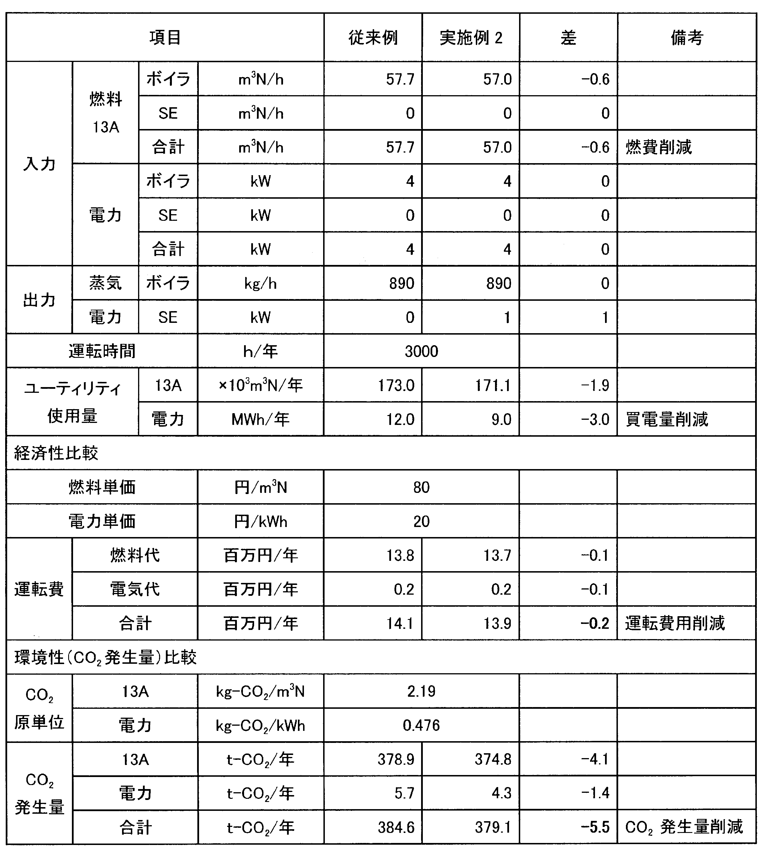
表2に示された結果を参照すると、実施例2においてはボイラ1、第2のスターリングエンジン21の合計の燃費とともに、外部から補機(ユーティリティ)に供給する電力(買電量)も削減されている。また、燃料代と電気代を合計した運転費用とともに、燃料と外部の電力に由来する二酸化炭素(CO2)発生量も削減されている。
なお、実施例2の発電機を組み込んだボイラシステムにおいても、実施例1の変形例と同様に、第2のスターリングエンジン21の低温熱源から排出されるボイラ給水の流路74から、第2の給水ポンプ23から第2のスターリングエンジン21にボイラ給水を供給する流路75に向けて循環ポンプでボイラ給水の一部を還流させてもよい。また、循環ポンプに代えて、低温熱源から排出されるボイラ給水の流路74から第2の給水ポンプ23の吸い込み側に流路を設けてボイラ給水の一部を還流させてもよい。また、実施例2の発電機を組み込んだボイラからエコノマイザ4を省略してもよい。
図6は、実施例3の発電機を組み込んだボイラシステムの全体の装置を示すブロック図である。実施例3の発電機を組み込んだボイラシステムは、燃焼熱を高温熱源とするスターリングエンジン発電装置と排熱を高温熱源とするスターリングエンジン発電装置の両方をボイラと組合せたものである。
実施例3の発電機を組み込んだボイラシステムには、ボイラ1が含まれ、このボイラ1には、燃料の都市ガス13Aが流路51を介して供給され、燃焼に用いられる空気が押し込み通風機の送風機2から流路52を介して供給され、予熱されたボイラ給水が流路53から供給されている。ボイラ1は、燃料と空気の燃焼熱を熱源とし、予熱されたボイラ給水を蒸発させて蒸気にしている。ボイラ1の換算蒸発量は1000kg/hであり、圧力0.7MPagで温度170℃の蒸気を流路54を介して890kg/hの流量で供給している。
また、実施例3の発電機を組み込んだボイラシステムには、第1のスターリングエンジン11が含まれ、この第1のスターリングエンジン11には、燃料の都市ガス13Aが流路61を介して供給され、燃焼に用いられる空気が流路62を介して供給され、冷却水に用いられるボイラ給水が流路81を介して供給されている。
第1のスターリングエンジン11は、第1の発電機12を備え、燃料と空気の燃焼熱を高温熱源とし、ボイラ給水を冷却水として低温熱源に用い、第1の発電機12を駆動している。これら第1のスターリングエンジン11と第1の発電機12とは、第1のスターリングエンジン発電装置10を構成している。第1の発電機12は、3kWの電力を線路63を介して送風機2と第2の給水ポンプ23とに供給している。第1のスターリングエンジン11は、排気を流路56を介して排出し、昇温されたボイラ給水を流路58を介して排出している。
さらに、実施例3の発電機を組み込んだボイラシステムには、第2のスターリングエンジン21が含まれ、この第2のスターリングエンジン21には、高温の熱媒体が流路71を介して供給され、ボイラ給水が第2の給水ポンプ23から流路75を介して供給されている。
第2のスターリングエンジン21は、第2の発電機22を備え、高温の熱媒体を高温熱源とし、ボイラ給水を冷却水として低温熱源に用い、第2の発電機22を駆動している。これら第2のスターリングエンジン21と第2の発電機22とは、第2のスターリングエンジン発電装置20を構成している。第2の発電機22は、1kWの電力を線路76を介してこの装置に備えられる送風機2と第2の給水ポンプ23とに供給している。
第2のスターリングエンジン21は、流路71から供給されて高温熱源に使用した熱媒体を流路72に排出している。また、流路75から供給されて低温熱源に使用したボイラ給水を流路81に排出している。
さらに、実施例3の発電機を組み込んだボイラシステムには、熱交換器3が含まれ、この熱交換器3には、第2のスターリングエンジン21の高温熱源の熱媒体が流路72を介して供給され、流路55を介したボイラ1の排気と流路56を介した第1のスターリングエンジン11の排気とを併せた排気が流路57を介して供給されている。熱交換器3は、流路57から供給された排気から流路72から供給された熱媒体に熱を移動し、加熱された熱媒体を流路71を介して第2のスターリングエンジン21に供給し、排気を流路73を介して排出している。
さらに、実施例3の発電機を組み込んだボイラシステムには、エコノマイザ4が含まれ、このエコノマイザ4には、第1のスターリングエンジン11から排出されたボイラ給水が流路58を介して供給され、熱交換器3の排気が流路73を介して供給されている。エコノマイザ4は、流路73から供給された排気から回収した熱で流路58から供給されたボイラ給水を加熱し、昇温したボイラ給水を流路53を介してボイラ1に供給している。エコノマイザ4で熱を回収された排気は、流路64を介して排出され、最終的に排気筒5を介して大気中に排出される。なお、実施例3においては、エコノマイザ4に限らず、レキュペレータを使用することもできる。
この実施例3の発電機を組み込んだボイラシステムにおいては、第1のスターリングエンジン発電装置10と第2のスターリングエンジン発電装置20とで発電した電力を送風機2と第2の給水ポンプ23とに供給している。第1のスターリングエンジン発電装置10と第2のスターリングエンジン発電装置20とから供給される電力が不足する場合には、外部から電力を供給して補充する。
この実施例3の発電機を組み込んだボイラシステムは、燃焼熱を高温熱源とする第1のスターリングエンジン発電装置10と排熱を高温熱源とする第2のスターリングエンジン発電装置20の両方をボイラ1と組合せ、低温のボイラ給水を第2のスターリングエンジン発電装置20と第1のスターリングエンジン発電装置10との低温熱源として使用することにより、低温熱源を確保し、かつ低温熱源の排熱でボイラ給水を予熱することで、ボイラ単独のシステムと比べ、同じ蒸発量を得るのに必要なボイラの燃料消費量を削減している。
また、ボイラ1からの排熱を第2のスターリングエンジン発電装置20の温度差発電の高温熱源とし、この電力を送風機2、第2の給水ポンプ23等のボイラ1システムの補機のモータに供給することにより、ボイラシステムの補機で消費する電力量を削減している。
ここで、実施例3の発電機を組み込んだボイラシステムを運転したときの諸量を図1に示した従来例と比較して算出した結果を表3に示す。この比較において、実施例3と従来例におけるシステムの構成、運転の条件等は共通であるものとする。なお、表における「SE」は第1のスターリングエンジン発電装置10と第2のスターリングエンジン発電装置20とを意味している。

表3に示された結果を参照すると、実施例3においてはボイラ1、第1のスターリングエンジン11、第2のスターリングエンジン21の合計の燃費とともに、外部から補機(ユーティリティ)に供給する電力(買電量)も削減されている。また、燃料代と電気代を合計した運転費用とともに、燃料と外部の電力に由来する二酸化炭素(CO2)発生量も削減されている。
実施例3の発電機を組み込んだボイラシステムにおいては、エコノマイザ4を省略することも可能である。エコノマイザ4を省略した場合、第1のスターリングエンジンの低温熱源から排出されるボイラ給水は流路58からエコノマイザ4を通ることなく流路53を経てボイラ1に供給される。また、熱交換器3からのボイラ1の排気はエコノマイザ4を通ることなく流路64を経て排気筒5に送られる。また、ボイラ給水は、第1のスターリングエンジン11、第2のスターリングエンジンの順に通水してもよい。
なお、実施例3の発電機を組み込んだボイラシステムにおいても、実施例1の変形例と同様に第1のスターリングエンジン発電装置10にレキュペレータ14を設け、高温熱源の排気から熱回収しボイラ給水を加熱してもよい。
また、実施例1の他の変形例と同様に、第1のスターリングエンジン11から排出されるボイラ給水の流路58から、第2のスターリングエンジン21から第1のスターリングエンジン11にボイラ給水を供給する流路81に向けてボイラ給水の一部を還流させる循環ポンプを設けてもよい。
また、第2のスターリングエンジン21の低温熱源から排出されるボイラ給水の流路81から、第2の給水ポンプ23から第2のスターリングエンジン21にボイラ給水を供給する流路75に向けて循環ポンプでボイラ給水の一部を還流させてもよい。さらに、この循環ポンプに換えて、第2のスターリングエンジン21から排出されるボイラ給水の流路81から第2の給水ポンプ23の吸い込み側に向かう流路を設けてボイラ給水の一部を還流させてもよい。
図7は、実施例4の発電機を組み込んだボイラシステムの全体の装置を示すブロック図である。実施例4の発電機を組み込んだボイラシステムは、実施例1の発電機を組み込んだボイラシステムの構成において、第1のスターリングエンジン発電装置10に冷却水を連続的に供給することができるようにバッファタンク91をさらに設けたものである。他の構成は、実施例1の発電機を組み込んだボイラシステムと同様である。
バッファタンク91は、所定の容量を有する容器であり、内部に所定量までの水111を貯蔵することができるように構成されている。このバッファタンク91には、内部の水111の水位を検出することができる水位計97が設けられている。図7においては、電極棒型の水位計97が示されているが、これに限らず他の種類の水位計を使用することができる。
バッファタンク91には、図示しない水供給源から流路92を介して水が供給されている。流路92には弁が設けられ、水位計97によって検出された水位に基づいて弁の開/閉を切り替え、バッファタンク91内の水111の水位が所定範囲内になるように制御している。
バッファタンク91からは、第1の給水ポンプ13によって、貯蔵された水が流路59を介して第1のスターリングエンジン11に冷却水として供給されている。この冷却水は、第1のスターリングエンジン11の低温熱源に使用された後で排出され、流路93を介してバッファタンク91に戻されている。また、バッファタンク91からは、第3の給水ポンプ95によって、貯蔵された水が流路58を介してエコノマイザ4を通じてボイラ給水に供給されている。
この実施例4においては、バッファタンク91と第1のスターリングエンジン11との間の流路59、93を介する閉じた循環ラインにより冷却水が連続して循環されている。一方、エコノマイザ4に供給されるボイラ給水は、循環ラインとは別の流路58によってバッファタンク91から送られている。
例えばボイラ1に小型貫流ボイラを使用した場合、ボイラ1内の水位によりボイラ給水を断続的に行うため、第3の給水ポンプ95が運転・停止を繰り返すことがある。このようなときにも、第1のスターリングエンジン11は、循環ラインを通じて冷却水を連続して供給することによって、連続的に運転することができる。したがって、ポンプ給水が断続的に行われる場合にも、第1のスターリングエンジン11の発電効率や内部温度などの維持が保証される。
なお、ボイラ1が停止してボイラ給水が止まった状態が続くと、循環ラインを冷却水が循環を続けてバッファタンク91に貯蔵された水111の温度が次第に上昇することがあり得る。この場合、第1のスターリングエンジン11の負荷を低減し、さらに、バッファタンク91に貯蔵された水が所定の温度まで上昇すると第1のスターリングエンジン11を停止することができる。
なお、本実施の形態においては、補機として送風機2と第2の給水ポンプ23とを例示したが、本発明はこれらに限られず所望の補機に適用することができる。また、本実施の形態で例示した第1のスターリングエンジン11と第2のスターリングエンジン21とに換えて熱音響発電装置を利用することもできる。さらに、本実施の形態では、燃料に都市ガス13Aを使用したが、本発明はこれに限られず燃焼熱を得られるものであればよく、例えばごみ、石油などであってもよい。
1 ボイラ
2 送風機
3 熱交換器
4 エコノマイザ
5 排気筒
10 第1のスターリングエンジン発電装置
11 第1のスターリングエンジン
12 第1の発電機
13 第1の給水ポンプ
14 レキュペレータ
20 第2のスターリングエンジン発電装置
21 第2のスターリングエンジン
22 第2の発電機
23 第2の給水ポンプ
91 バッファタンク
2 送風機
3 熱交換器
4 エコノマイザ
5 排気筒
10 第1のスターリングエンジン発電装置
11 第1のスターリングエンジン
12 第1の発電機
13 第1の給水ポンプ
14 レキュペレータ
20 第2のスターリングエンジン発電装置
21 第2のスターリングエンジン
22 第2の発電機
23 第2の給水ポンプ
91 バッファタンク
Claims (16)
- ボイラと、
発電機を駆動し、燃焼熱を高温熱源とするスターリングエンジンとを含み、
前記ボイラは燃焼熱とともに前記スターリングエンジンの排熱を蒸気発生の熱源とする発電機を組み込んだボイラシステム。 - 前記ボイラの排気から排熱を回収するエコノマイザをさらに含み、前記スターリングエンジンの排熱は前記エコノマイザを介して前記ボイラに供給され、前記ボイラは前記スターリングエンジンの排熱に加えて前記エコノマイザで回収された前記ボイラの排熱も蒸気発生の熱源に含む請求項1に記載の発電機を組み込んだボイラシステム。
- 前記スターリングエンジンの排気から排熱を回収するレキュペレータをさらに含み、前記ボイラは前記レキュペレータで回収された排熱も蒸気発生の熱源に含む請求項1に記載の発電機を組み込んだボイラシステム。
- 前記ボイラの排気から排熱を回収するエコノマイザ及び前記スターリングエンジンの排気から排熱を回収するレキュペレータをさらに含み、前記ボイラはエコノマイザで回収された排熱及び前記レキュペレータで回収された排熱も蒸気発生の熱源に含む請求項1に記載の発電機を組み込んだボイラシステム。
- 前記スターリングエンジンは、前記ボイラに供給されるボイラ給水を低温熱源に使用して予熱し、この予熱されたボイラ給水により前記ボイラに排熱を提供する請求項1から4のいずれか一項に記載の発電機を組み込んだボイラシステム。
- 送風機及び給水ポンプをさらに含み、前記スターリングエンジンからの電力は前記送風機及び給水ポンプに供給される請求項1から5のいずれか一項に記載の発電機を組み込んだボイラシステム。
- ボイラと、
発電機を駆動し、前記ボイラの排熱を高温熱源とするスターリングエンジンとを含み、
前記ボイラは燃焼熱及び前記スターリングエンジンの排熱を蒸気発生の熱源とする発電機を組み込んだボイラシステム。 - 前記ボイラの排気から熱を回収する熱交換器をさらに含み、前記スターリングエンジンには前記熱交換器で回収された前記ボイラの排熱が高温熱源として供給される請求項7に記載の発電機を組み込んだボイラシステム。
- 前記熱交換器の排気から回収した排熱を前記ボイラの蒸気発生の熱源に提供するエコノマイザをさらに含む請求項8に記載の発電機を組み込んだボイラシステム。
- 前記スターリングエンジンは、前記ボイラに供給されるボイラ給水を低温熱源として使用して予熱し、この予熱されたボイラ給水により前記ボイラに排熱を提供する請求項7から9のいずれか一項に記載の発電機を組み込んだボイラシステム。
- 送風機及び給水ポンプの少なくとも一方をさらに含み、前記スターリングエンジンからの電力は前記少なくとも一方に供給される請求項7から10のいずれか一項に記載の発電機を組み込んだボイラシステム。
- ボイラと、
第1の発電機を駆動し、燃焼熱を高温熱源とする第1のスターリングエンジンと、
第2の発電機を駆動し、前記ボイラの排熱を高温熱源とする第2のスターリングエンジンとを含み、
前記ボイラは燃焼熱とともに前記第1のスターリングエンジン及び前記第2のスターリングエンジンの排熱を蒸気発生の熱源とする発電機を組み込んだボイラシステム。 - 前記ボイラの排気から熱を回収する熱交換器をさらに含み、前記第2のスターリングエンジンには前記熱交換器で回収された前記ボイラの排熱が高温熱源として供給される請求項12に記載の発電機を組み込んだボイラシステム。
- 前記熱交換器の排気から排熱を回収するエコノマイザをさらに含み、前記第1のスターリングエンジンの排熱は前記エコノマイザまたはレキュペレータを介して前記ボイラに供給され、前記ボイラは前記第1のスターリングエンジンの排熱に加えて前記エコノマイザで回収された前記ボイラの排熱も蒸気発生の熱源に含む請求項13に記載の発電機を組み込んだボイラシステム。
- 前記第1のスターリングエンジン及び第2のスターリングエンジンは、前記ボイラに供給されるボイラ給水を低温熱源として使用して予熱し、この予熱されたボイラ給水により前記ボイラに排熱を提供する請求項12から14のいずれか一項に記載の発電機を組み込んだボイラシステム。
- 送風機及び給水ポンプをさらに含み、前記第1のスターリングエンジン及び前記第2のスターリングエンジンからの電力は前記送風機及び給水ポンプに供給される請求項12から15のいずれか一項に記載の発電機を組み込んだボイラシステム。
Priority Applications (1)
| Application Number | Priority Date | Filing Date | Title |
|---|---|---|---|
| JP2016534434A JPWO2016010015A1 (ja) | 2014-07-14 | 2015-07-14 | 発電機を組み込んだボイラシステム |
Applications Claiming Priority (2)
| Application Number | Priority Date | Filing Date | Title |
|---|---|---|---|
| JP2014-144369 | 2014-07-14 | ||
| JP2014144369 | 2014-07-14 |
Publications (1)
| Publication Number | Publication Date |
|---|---|
| WO2016010015A1 true WO2016010015A1 (ja) | 2016-01-21 |
Family
ID=55078505
Family Applications (1)
| Application Number | Title | Priority Date | Filing Date |
|---|---|---|---|
| PCT/JP2015/070097 Ceased WO2016010015A1 (ja) | 2014-07-14 | 2015-07-14 | 発電機を組み込んだボイラシステム |
Country Status (2)
| Country | Link |
|---|---|
| JP (2) | JPWO2016010015A1 (ja) |
| WO (1) | WO2016010015A1 (ja) |
Cited By (3)
| Publication number | Priority date | Publication date | Assignee | Title |
|---|---|---|---|---|
| CN107387259A (zh) * | 2017-08-30 | 2017-11-24 | 株洲新奥燃气有限公司 | 一种可用于冷热电三联供的制热系统、可用于冷热电三联供的制冷系统及冷热电三联供系统 |
| KR101875379B1 (ko) * | 2018-02-08 | 2018-07-06 | 박판호 | 증기를 이용한 발전 장치 및 방법 |
| CN113864770A (zh) * | 2021-10-14 | 2021-12-31 | 华电国际电力股份有限公司天津开发区分公司 | 循环流化床锅炉的返料风系统 |
Families Citing this family (1)
| Publication number | Priority date | Publication date | Assignee | Title |
|---|---|---|---|---|
| CN108223188B (zh) * | 2018-01-16 | 2023-09-26 | 昆明理工大学 | 一种基于斯特林发动机的废热发电嵌入式实时控制装置 |
Citations (6)
| Publication number | Priority date | Publication date | Assignee | Title |
|---|---|---|---|---|
| JPS63235650A (ja) * | 1987-03-20 | 1988-09-30 | Kawasaki Heavy Ind Ltd | 熱電併給システム |
| JPH0894050A (ja) * | 1994-09-29 | 1996-04-12 | Hitachi Eng Co Ltd | 排熱利用発電装置 |
| JP2003299397A (ja) * | 2002-03-29 | 2003-10-17 | Ntt Power & Building Facilities Inc | コージェネレーション型ゴミ処理システム |
| JP2005273556A (ja) * | 2004-03-25 | 2005-10-06 | Mitsubishi Heavy Ind Ltd | 予混合燃焼機関による発電装置 |
| JP2008175151A (ja) * | 2007-01-19 | 2008-07-31 | Chugoku Electric Power Co Inc:The | 液化ガスの冷熱を利用したコージェネレーションシステム及びその運転方法 |
| JP2010117095A (ja) * | 2008-11-14 | 2010-05-27 | Ebara Corp | 腐食抑制方法 |
Family Cites Families (3)
| Publication number | Priority date | Publication date | Assignee | Title |
|---|---|---|---|---|
| JP4375908B2 (ja) * | 2001-01-25 | 2009-12-02 | 大阪瓦斯株式会社 | 排熱回収システム |
| JP2014070751A (ja) * | 2012-09-28 | 2014-04-21 | Miura Co Ltd | 蒸気発生システム |
| JP2016010015A (ja) * | 2014-06-24 | 2016-01-18 | 聡 大森 | 通信システム及び通信端末 |
-
2015
- 2015-07-14 JP JP2016534434A patent/JPWO2016010015A1/ja active Pending
- 2015-07-14 WO PCT/JP2015/070097 patent/WO2016010015A1/ja not_active Ceased
-
2018
- 2018-01-24 JP JP2018009811A patent/JP6616850B2/ja active Active
Patent Citations (6)
| Publication number | Priority date | Publication date | Assignee | Title |
|---|---|---|---|---|
| JPS63235650A (ja) * | 1987-03-20 | 1988-09-30 | Kawasaki Heavy Ind Ltd | 熱電併給システム |
| JPH0894050A (ja) * | 1994-09-29 | 1996-04-12 | Hitachi Eng Co Ltd | 排熱利用発電装置 |
| JP2003299397A (ja) * | 2002-03-29 | 2003-10-17 | Ntt Power & Building Facilities Inc | コージェネレーション型ゴミ処理システム |
| JP2005273556A (ja) * | 2004-03-25 | 2005-10-06 | Mitsubishi Heavy Ind Ltd | 予混合燃焼機関による発電装置 |
| JP2008175151A (ja) * | 2007-01-19 | 2008-07-31 | Chugoku Electric Power Co Inc:The | 液化ガスの冷熱を利用したコージェネレーションシステム及びその運転方法 |
| JP2010117095A (ja) * | 2008-11-14 | 2010-05-27 | Ebara Corp | 腐食抑制方法 |
Cited By (5)
| Publication number | Priority date | Publication date | Assignee | Title |
|---|---|---|---|---|
| CN107387259A (zh) * | 2017-08-30 | 2017-11-24 | 株洲新奥燃气有限公司 | 一种可用于冷热电三联供的制热系统、可用于冷热电三联供的制冷系统及冷热电三联供系统 |
| CN107387259B (zh) * | 2017-08-30 | 2023-08-04 | 株洲新奥燃气有限公司 | 制热系统、制冷系统及冷热电三联供系统 |
| KR101875379B1 (ko) * | 2018-02-08 | 2018-07-06 | 박판호 | 증기를 이용한 발전 장치 및 방법 |
| CN113864770A (zh) * | 2021-10-14 | 2021-12-31 | 华电国际电力股份有限公司天津开发区分公司 | 循环流化床锅炉的返料风系统 |
| CN113864770B (zh) * | 2021-10-14 | 2023-08-22 | 华电国际电力股份有限公司天津开发区分公司 | 循环流化床锅炉的返料风系统 |
Also Published As
| Publication number | Publication date |
|---|---|
| JP6616850B2 (ja) | 2019-12-04 |
| JP2018084237A (ja) | 2018-05-31 |
| JPWO2016010015A1 (ja) | 2017-04-27 |
Similar Documents
| Publication | Publication Date | Title |
|---|---|---|
| US10823015B2 (en) | Gas-steam combined cycle centralized heat supply device and heat supply method | |
| CN104204427B (zh) | 具备朗肯循环发动机的燃气涡轮发动机装置 | |
| JP2021185313A (ja) | 発電システム | |
| JP6616850B2 (ja) | 発電装置を組み込んだボイラシステム | |
| JP2009299682A (ja) | 発生した排熱をターボ機械の補助システムによって回収するためのシステム | |
| JP6458026B2 (ja) | 燃料電池排熱による発電システム | |
| CN101806250A (zh) | 用于预热燃料的废热利用 | |
| KR20150028743A (ko) | 증기 터빈 플랜트 | |
| KR101271188B1 (ko) | 선박용 폐열 회수 시스템 | |
| KR101814878B1 (ko) | 선박 추진 시스템 및 선박 및 선박 추진 시스템의 운전 방법 | |
| KR101399428B1 (ko) | Orc 발전시스템의 안전장치 | |
| US20190264579A1 (en) | Thermal power station | |
| KR101303811B1 (ko) | 폐열을 활용한 복합화력 발전시스템 | |
| JP2014122576A (ja) | 太陽熱利用システム | |
| Tahmasebipour et al. | Conceptual design of a super-critical CO2 brayton cycle based on stack waste heat recovery for shazand power plant in Iran | |
| US20180023422A1 (en) | Heat exchanger, energy recovery system, and vessel | |
| CN102105656B (zh) | 混合发电装置 | |
| KR20160017283A (ko) | 초임계 이산화탄소 발전시스템 | |
| JP2013194926A (ja) | 蒸気発生システム | |
| JP6136722B2 (ja) | ボイラシステム | |
| JP2016200083A (ja) | 発電システム | |
| KR101999448B1 (ko) | 초임계 이산화탄소 작동 유체를 이용한 하이브리드 발전 시스템 | |
| CN105705735A (zh) | 利用发电机的废热的热力发电厂 | |
| US9857074B2 (en) | Boiler water supply preheater system and boiler water supply preheating method | |
| EP3124757A1 (en) | Integrated heat and power plant using geothermal energy |
Legal Events
| Date | Code | Title | Description |
|---|---|---|---|
| 121 | Ep: the epo has been informed by wipo that ep was designated in this application |
Ref document number: 15822028 Country of ref document: EP Kind code of ref document: A1 |
|
| ENP | Entry into the national phase |
Ref document number: 2016534434 Country of ref document: JP Kind code of ref document: A |
|
| NENP | Non-entry into the national phase |
Ref country code: DE |
|
| 122 | Ep: pct application non-entry in european phase |
Ref document number: 15822028 Country of ref document: EP Kind code of ref document: A1 |