WO2016009655A1 - 管路内浄化装置および管路内浄化システム - Google Patents
管路内浄化装置および管路内浄化システム Download PDFInfo
- Publication number
- WO2016009655A1 WO2016009655A1 PCT/JP2015/003621 JP2015003621W WO2016009655A1 WO 2016009655 A1 WO2016009655 A1 WO 2016009655A1 JP 2015003621 W JP2015003621 W JP 2015003621W WO 2016009655 A1 WO2016009655 A1 WO 2016009655A1
- Authority
- WO
- WIPO (PCT)
- Prior art keywords
- pipe
- microbial carrier
- carrier
- microbial
- curved member
- Prior art date
- Legal status (The legal status is an assumption and is not a legal conclusion. Google has not performed a legal analysis and makes no representation as to the accuracy of the status listed.)
- Ceased
Links
Images










Classifications
-
- C—CHEMISTRY; METALLURGY
- C02—TREATMENT OF WATER, WASTE WATER, SEWAGE, OR SLUDGE
- C02F—TREATMENT OF WATER, WASTE WATER, SEWAGE, OR SLUDGE
- C02F3/00—Biological treatment of water, waste water, or sewage
- C02F3/02—Aerobic processes
- C02F3/06—Aerobic processes using submerged filters
-
- E—FIXED CONSTRUCTIONS
- E03—WATER SUPPLY; SEWERAGE
- E03F—SEWERS; CESSPOOLS
- E03F5/00—Sewerage structures
-
- Y—GENERAL TAGGING OF NEW TECHNOLOGICAL DEVELOPMENTS; GENERAL TAGGING OF CROSS-SECTIONAL TECHNOLOGIES SPANNING OVER SEVERAL SECTIONS OF THE IPC; TECHNICAL SUBJECTS COVERED BY FORMER USPC CROSS-REFERENCE ART COLLECTIONS [XRACs] AND DIGESTS
- Y02—TECHNOLOGIES OR APPLICATIONS FOR MITIGATION OR ADAPTATION AGAINST CLIMATE CHANGE
- Y02W—CLIMATE CHANGE MITIGATION TECHNOLOGIES RELATED TO WASTEWATER TREATMENT OR WASTE MANAGEMENT
- Y02W10/00—Technologies for wastewater treatment
- Y02W10/10—Biological treatment of water, waste water, or sewage
Definitions
- the present invention relates to an in-pipe purification device and an in-pipe purification system.
- Patent Document 1 discloses a sewage purification apparatus for a pipeline that purifies sewage by bringing sewage into contact with useful microorganisms by providing a film of a ceramic material containing a group of useful microorganisms on the inner surface of the pipeline. .
- Patent Document 2 discloses that a water-permeable fixed bed in which microorganisms can be settled in a pipeline, and oxygen is supplied to the fixed bed even in a state immersed in the fixed bed, and aerobic microorganisms are allowed to grow.
- a water purification device for a pipeline that can be promoted is disclosed.
- Patent Document 3 fins are provided on the inside of the pipeline of the pressure feeding pipe, and a plurality of pipes are installed inside the pressure feeding pipe, thereby expanding the area where the sewage and the microorganisms come into contact with each other. A method of purification is disclosed.
- Patent Document 4 discloses an in-pipe purification device that can purify sewage at low cost and high efficiency.
- JP-A-8-165704 JP 2010-024773 A Japanese Utility Model Publication No. 6-24799 International Publication No. 2013 / 172288A1
- An object of the present invention is to provide an in-pipe purification device and a in-pipe purification system capable of purifying sewage at a low cost and with high efficiency while ensuring sufficient flow-down performance.
- An in-pipe purification apparatus is the in-pipe purification apparatus installed in the pipe line, wherein at least a part of the cross section is formed along the curved surface of the pipe line, and at least of the curved member A microorganism carrier is formed around a part of the circumference or the inner circumference.
- the microbial carrier is deficient on the lowermost surface of the pipeline when installed in the pipeline.
- the microbial carrier is formed around or on the inner peripheral side of at least a part of the curved member, the purification action by the microbial carrier can be maintained while ensuring the flow rate at the lowest part of the pipe.
- the microbial carrier is deficient in the lowermost surface of the pipeline when installed in the pipeline, the flow rate can be reliably ensured in the lowermost portion of the pipeline. Further, when the flow rate is small, the flow rate is not reduced, and when the flow rate is large, purification can be performed.
- An in-pipe purification apparatus is the in-pipe purification apparatus according to one aspect, wherein the curved surface member may be missing on the lowermost surface of the pipe line when installed in the pipe line.
- the in-pipe purification device is smaller than the pipe, it is easy to install the in-pipe purification device in the pipe.
- An in-pipe purification apparatus is the in-pipe purification apparatus according to one aspect or the second aspect of the present invention, wherein the microbial carriers are respectively disposed at both ends of the curved member. And a second microbial carrier.
- the microbial carriers are respectively disposed at both ends of the curved member, they can be separately disposed at both ends that are likely to contribute to purification. Therefore, the purification efficiency with respect to the material amount of the microorganism carrier is good.
- An in-pipe purification apparatus is the in-pipe purification apparatus installed in the pipe line according to the third aspect of the present invention from the one aspect, and the first microorganism carrier disposed on the curved member A second microbial carrier, and the first microbial carrier and the second microbial carrier are arranged to face each other across the lowermost part of the curved member when installed in the pipe. is there.
- the first microbial carrier and the second microbial carrier are arranged opposite to each other with the lowermost part interposed therebetween, the first microbial carrier and the second microbial carrier are secured while ensuring a flow rate at the lowermost part of the pipe.
- the purifying action by the two microbial carriers can also be maintained. Further, when the flow rate is small, the flow rate is not reduced, and when the flow rate is large, purification can be performed.
- the term “opposite” means that the first microbial carrier and the second microbial carrier are opposed to each other in a cross section having a predetermined angle as well as perpendicular to the pipeline (the state where the pipeline axis is a normal line). Including cases. That is, the case where the first microbial carrier and the second microbial carrier are arranged in a zigzag state along the longitudinal direction of the pipeline is included.
- An in-pipe purification apparatus is the in-pipe purification apparatus according to the fourth aspect of the invention, wherein the curved member is disposed beyond the ends of the first microbial carrier and the second microbial carrier. May be.
- fixing members are provided at both ends of the curved member. Both ends where the first microbial carrier and the second microbial carrier are not disposed, such as being brought into contact with the inner peripheral surface of the tube, can also be used for fixing the in-pipe purification device. Therefore, fixing of the in-pipe purification device can be facilitated.
- the in-pipe purification apparatus is the in-pipe purification apparatus according to the third to fifth aspects of the present invention, wherein the distance between the first microbial carrier and the second microbial carrier is a curved member. It may be arranged so as to have a distance in the range of 10% to 40% of the pipe diameter in the case.
- the in-pipe purification apparatus is the in-pipe purification apparatus according to the third to sixth aspects, wherein the first microbial carrier and the second microbial carrier have a thickness in the range of 5 mm to 50 mm. It may be formed.
- the first microbial carrier and the second microbial carrier are less than 5 mm, there is a problem that the microorganisms cannot be held at a high density and the reactivity is lowered, and if it is more than 50 mm, the resistance becomes high and the flow rate is lowered. There is a problem to do.
- An in-pipe purification apparatus is the in-pipe purification apparatus according to the third to seventh inventions, wherein the first microbial carrier and the second microbial carrier have a total width of the pipe line It may be formed within a range of 30% to 95% of the inner circumference.
- the first microbial carrier and the second microbial carrier have a problem that the reactivity decreases when the total width is less than 30%, and when the width exceeds 95%, the resistance increases and the flow rate becomes high. There is a problem that decreases.
- the in-pipe purification apparatus according to the ninth invention is the in-pipe purification apparatus according to the third to eighth inventions, wherein the first microbial carrier and the second microbial carrier are provided with curved members. It may be formed continuously in the longitudinal direction of the pipe.
- the first microbial carrier and the second microbial carrier may be formed continuously in the longitudinal direction of the conduit when the curved member is installed.
- the reaction efficiency can be further improved while ensuring the flow rate.
- An in-pipe purification apparatus is the in-pipe purification apparatus according to the third to ninth aspects of the invention, wherein the curved surface member is that of the pipe line when the curved surface member is installed in the pipe line. It may be formed to have a length in the range of 30% to 95% of the inner circumference.
- the curved member has a length of less than 30% of the inner circumference of the pipeline, the installation of the curved member becomes unstable, and if the length is more than 95% of the inner circumference of the pipeline, Installation of the curved member becomes difficult.
- An in-pipe purification apparatus is the in-pipe purification apparatus according to the tenth aspect of the invention from one aspect, wherein the curved member includes a fixing portion that performs positioning for placement in the pipe. But you can.
- the flow velocity can be ensured by appropriately positioning the lowermost portion of the curved member by the fixing portion.
- the fixing portion may use a technique such as fitting, locking, welding, welding, adhesion, screw, or bolt.
- An in-pipe purification system includes a pipe, a curved member in which at least a part of a cross section is formed along a curved surface of the pipe, and a microorganism carrier disposed on the curved member.
- a microbial carrier is formed around or on the inner peripheral side of at least a part of the curved member, and the microbial carrier is disposed on the lowermost surface of the pipeline when installed in the pipeline. It is missing.
- the microbial carrier is formed around or on the inner peripheral side of at least a part of the curved member, the purification action by the microbial carrier can be maintained while ensuring the flow rate at the lowest part of the pipe.
- the microbial carrier is deficient in the lowermost surface of the pipeline when installed in the pipeline, the flow rate can be reliably ensured in the lowermost portion of the pipeline. Further, when the flow rate is small, the flow rate is not reduced, and when the flow rate is large, purification can be performed.
- the in-pipe purification system according to a thirteenth invention is the in-management purification system according to the twelfth invention, wherein the curved member is missing on the lowermost surface of the pipe when installed in the pipe. Also good.
- the first microbial carrier and the second microbial carrier are arranged opposite to each other with the lowermost part interposed therebetween, the first microbial carrier and the second microbial carrier are secured while ensuring a flow rate at the lowermost part of the pipe.
- the purifying action by the two microbial carriers can also be maintained. Further, when the flow rate is small, the flow rate is not reduced, and when the flow rate is large, purification can be performed.
- the in-pipe purification system according to a fourteenth aspect of the present invention is the in-pipe purification system according to another aspect or the thirteenth aspect of the present invention, wherein the microbial carrier includes a first microbial carrier and a second microbial carrier.
- the first microbial carrier and the second microbial carrier may be arranged to face each other with the lowermost part of the curved member interposed therebetween.
- the first microbial carrier and the second microbial carrier are arranged opposite to each other with the lowermost part interposed therebetween, the first microbial carrier and the second microbial carrier are secured while ensuring a flow rate at the lowermost part of the pipe.
- the purifying action by the two microbial carriers can also be maintained. Further, when the flow rate is small, the flow rate is not reduced, and when the flow rate is large, purification can be performed.
- the term “opposite” means that the first microbial carrier and the second microbial carrier are opposed to each other in a cross section having a predetermined angle as well as perpendicular to the pipeline (the state where the pipeline axis is a normal line). Including cases. That is, the case where the first microbial carrier and the second microbial carrier are arranged in a zigzag state along the longitudinal direction of the pipeline is included.
- the in-pipe purification system according to a fifteenth aspect of the present invention is the in-management purification system according to the fourteenth aspect of the present invention from another aspect, further comprising a connecting member connected to the conduit, wherein the connecting member is a pipe in the conduit. You may provide the installation part which installs a road purification apparatus.
- connection member since the connection member includes an installation portion that installs the in-pipe purification device in the pipeline, the directionality of the connection member can be easily recognized, so that the installation becomes easy.
- the relative positional relationship between the position of the connection member and the in-pipe purification device can be adjusted by the installation unit.
- the first microbial carrier and the second microbial carrier can be arranged to face each other with the lowermost portion of the curved member interposed therebetween.
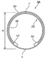
- FIG. 1 shows an example of the in-pipe purification device 100
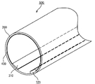
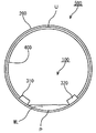
- FIGS. 2 and 3 show the state of the in-pipe purification system 500 in which the in-pipe purification device 100 is disposed in the pipe 200.
- FIG. 1 shows an example of the in-pipe purification device 100
- FIGS. 2 and 3 show the state of the in-pipe purification system 500 in which the in-pipe purification device 100 is disposed in the pipe 200.
- FIG. 1 shows an example of the in-pipe purification device 100
- FIGS. 2 and 3 show the state of the in-pipe purification system 500 in which the in-pipe purification device 100 is disposed in the pipe 200.
- the in-pipe purification apparatus 100 mainly includes microbial carriers 310 and 320 and a curved member 400.
- the curved member 400 is a curved surface along the inner peripheral surface of the pipe 200 (see FIG. 2) described later. Microbial carriers 310 and 320 are provided at the end of the curved member 400.
- the curved member 400 has an outer peripheral diameter slightly larger than the inner peripheral diameter of the pipe 200 and is made of an elastic body. As a result, the microorganism carriers 310 and 320 can be brought closer due to the elasticity of the curved member 400.
- the outer peripheral diameter of the curved member 400 is smaller than the inner peripheral diameter of the pipe 200, and the in-pipe purification device 100 can be disposed on the inner periphery of the pipe 200.
- the microorganism carriers 310 and 320 are provided to face each other with the lowermost part P interposed therebetween. Further, the curved member 400 is formed in a circumference including the uppermost portion U without including the lowermost portion P so as not to exist in the vicinity of the lowermost portion P.
- the lowermost part P indicates a point positioned at the lowermost part of the pipe 200
- the uppermost part U indicates a point positioned at the uppermost part of the pipe 200.
- examples of the material constituting the curved member 400 include resins such as polyethylene and vinyl chloride, fibers such as fiber reinforced plastic, steel, and ductile cast iron, and reinforced concrete.
- the microbial carriers 310 and 320 are provided to face each other at a distance L1.
- the microbial carriers 310 and 320 in the present embodiment have a thickness of t1 and a width of L3.
- the thickness (t1) is formed within a range of 5 mm or more and 50 mm or less
- the total width (L3) of the microorganism carrier is a range of 30% or more and 95% or less of the inner circumference of the pipe. Formed in.
- the microbial carriers 310 and 320 have a problem that the microorganisms cannot be held at a high density when the thickness t1 is less than 5 mm, and the reactivity is lowered.
- the thickness t1 exceeds 50 mm, the resistance becomes high and the flow rate is lowered.
- the microbial carriers 310 and 320 have a problem that the reactivity decreases when the total width is less than 30%, and there is a problem that when the width exceeds 95%, the resistance increases and the flow rate decreases. Therefore, it is preferable that it is said size.
- the microbial carriers 310 and 320 are made of a granular or small piece material used for attaching aerobic microorganisms or the like. Specifically, the material constituting the microbial carriers 310 and 320 is made of a resin such as polyethylene, polypropylene, or polyurethane, or ceramics.
- the microbial carriers 310 and 320 require water permeability, when the microbial carriers 310 and 320 are made of a hydrophobic material such as polyethylene or polypropylene, it is preferable that the microbial carriers 310 and 320 have been subjected to a hydrophilic treatment.
- the microbial carriers 310 and 320 are required to efficiently contact oxygen and microorganisms (aerobic microorganisms), they have a large surface area and are not easily clogged with fibrous bodies, foams, porous bodies, or It is preferable to use a net or the like.
- the microbial carriers 310 and 320 are made of a foam
- a closed cell type may be used.
- the shapes of the microorganism carriers 310 and 320 may be, for example, spherical, rectangular parallelepiped, cubic, sheet, fiber, or net.
- the microbial carriers 310 and 320 will be described as a rectangular parallelepiped shape.
- the microbial carriers 310 and 320 may be sealed in a container having higher water permeability, such as a net or a perforated tube.
- the microbial carriers 310 and 320 are made of a fibrous body, a foamed body, a porous body, a net-like body, or the like, one having a high porosity is preferable in order to increase the surface area of the microbial carriers 310 and 320.
- the porosity is preferably more than 50%, more preferably more than 80%.
- said porosity means what represented the ratio of the clearance gap per unit volume by 100 fraction.
- the distance (L1) between the microbial carriers 310 and 320 is within a range of 10% to 40% of the diameter R2 of the in-pipe purification system 500. It is. Further, as shown in FIG. 3, the in-pipe purification device 100 is formed to extend along the extending direction of the pipe 200. In the present embodiment, the curved member 400 is formed to extend along the extending direction of the pipe 200. However, the present invention is not limited to this, and the curved member 400 is spaced at a constant distance. It may be formed.
- the pipe 200 shown in FIGS. 2 and 3 is not particularly limited as long as it is a material that can be used as a sewage pipe, resin such as polyethylene and polyvinyl chloride, fiber reinforced plastic, steel, metal such as ductile cast iron, and reinforced concrete. It may consist of etc.
- the cross-sectional shape of the pipe 200 may be a pipe having a closed cross-sectional shape such as a circular shape or an oval shape, but is preferably a circular shape.
- the curved-surface-shaped member 400 is formed along each inner periphery.
- FIGS. 4 and 5 are schematic cross-sectional views for explaining a case where sewage flows into the in-pipe purification system 500.
- the microorganism carriers 310 and 320 can be purified by being immersed in the sewage WH.
- the microbial carriers 310 and 320 repeat the immersion with sewage and the exposure with air according to the water level in the pipeline.
- microorganisms as described above, the microbial carriers 310 and 320 repeat the immersion with sewage and the exposure with air according to the water level in the pipeline.
- microorganisms as described above, the microbial carriers 310 and 320 repeat the immersion with sewage and the exposure with air according to the water level in the pipeline.
- microorganisms as described above, the microbial carriers 310 and 320 repeat the immersion with sewage and the exposure with air according to the water level in the pipeline.
- FIGS. 6 to 9 are schematic views showing other examples of the in-pipe purification system 500 and the in-pipe purification device 100 shown in FIGS.
- FIG. 6 is a schematic diagram illustrating another example of the in-pipe purification apparatus 100
- FIG. 7 is a schematic diagram illustrating another example of the in-pipe purification system 500.
- FIG. 8 is a schematic diagram showing another example of the in-pipe purification device 100
- FIG. 9 is a schematic diagram showing another example of the in-pipe purification system 500.
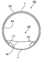
- the in-pipe purification device 100a is different from the in-pipe purification device 100 in that a microbial carrier 330a is formed instead of the microbial carriers 310 and 320.
- the microorganism carrier 330a is provided on the entire inner peripheral side of the curved member 400a.
- the microorganism carrier 330a is provided on the entire inner peripheral side of the curved member 400a.
- the present invention is not limited to this, and the microorganism carrier 330a may be provided on the entire periphery of the curved member 400a.
- the microbial carrier 330a in FIG. 6 and FIG. 7 is disposed so as not to be disposed at the lowermost part in the pipe 200, the problem that the resistance becomes high and the flow velocity decreases is less likely to occur.
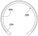
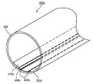
- the in-pipe purification device 100b is provided with a curved member 400b instead of the curved member 400a of the in-pipe purification device 100a.
- the curved surface member 400b is shorter than the curved surface member 400a, and the microbial carrier 330b having a thickness larger than that of the microbial carrier 330a is formed at the end of the curved surface member 400b formed shorter than the curved surface member 400a.
- the curved member 400b is not formed in a portion that is highly likely to be immersed in sewage, but a microbial carrier 330b is formed instead.
- microorganisms as a result, the immersion with sewage and the exposure with air are repeated, and microorganisms (aerobic microorganisms) naturally adhere to the microorganism carriers 330a and 330b to proliferate, thereby allowing the purification action to work.
- FIGS. 10 to 12 are schematic diagrams illustrating an example of the in-pipe purification apparatus 100.
- FIG. 10 shows another example of the in-pipe purification apparatus 100
- FIGS. 11 and 12 show the state of the in-pipe purification system 500c in which the in-pipe purification apparatus 100c is disposed in the pipe 200.
- FIG. 10 shows another example of the in-pipe purification apparatus 100
- FIGS. 11 and 12 show the state of the in-pipe purification system 500c in which the in-pipe purification apparatus 100c is disposed in the pipe 200.
- the in-pipe purification apparatus 100c mainly includes microbial carriers 310c and 320c, a curved surface member 400c, and a fixing portion 450c.
- the curved member 400c is a curved surface along the inner peripheral surface of the pipe 200 (see FIG. 11). Microbial carriers 310c and 320c are provided at the end of the curved member 400c. The microorganism carriers 310c and 320c are provided to face each other with the lowermost part P interposed therebetween. Here, the lowest part P shows the point located in the lowest part of the piping 200. FIG. 11
- the in-pipe purification device 100c is fixed to the lowermost portion P of the pipe 200 by the fixing portion 450c.
- the fixing portion 450 c is for fixing the in-pipe purification device 100 c to the pipe 200.
- the fixing portion 450c is a screw, a bolt, a welded body, or the like.
- the microorganism carriers 310c and 320c are provided to face each other at a distance L1.
- the microbial carriers 310c and 320c have a thickness of t1 and a width of L3.
- the thickness (t1) is formed within a range of 5 mm to 50 mm
- the total width (L3) is formed within a range of 30% to 95% of the inner circumference of the pipe.
- the microorganism carriers 310c and 320c have a problem that the microorganisms cannot be held at a high density when the thickness t1 is less than 5 mm, and the reactivity is lowered. When the thickness is more than 50 mm, the resistance is increased and the flow rate is lowered. In addition, the microbial carriers 310c and 320c have a problem that the reactivity decreases when the width is less than 30% of the inner circumference of the pipeline, and the resistance is high when the width exceeds 95% of the inner circumference of the pipeline. There is a problem that the flow velocity decreases. Therefore, it is preferable that it is said size.
- FIGS. 13 and 14 are schematic views showing still another example of the in-pipe purification apparatus 100.
- FIG. FIG. 13 shows another example of the in-pipe purification device 100
- FIG. 14 shows another example of the in-pipe purification system 500 in which the in-pipe purification device 100 is disposed in the pipe 200. Only the differences from the in-pipe purification device 100c and the in-pipe purification system 500c of FIGS. 10 to 12 will be described below.
- the curved member 400d is formed so as not to contact the inner peripheral surface (bottom surface) of the pipe 200, and the microorganism carriers 310d and 320d are attached to the end of the curved member 400d. . This makes it easier to fix the microorganism carrier to the curved member 400d.
- the curved member 400d has a fixed portion 450d.
- the fixing portion 450d is for floating and fixing the in-pipe purification device 100d from the inner peripheral surface of the pipe 200.
- the microbial carriers 310d and 320d have a rectangular parallelepiped shape, it is possible to further increase the surface area in contact with the sewage by forming irregularities.
- the curved surface rate of the curved member 400d is made constant, it is not limited to this, and at least a part should just be along the internal peripheral surface of the piping 200.
- the in-pipe purification system 500d can improve the purification efficiency by providing the in-pipe purification device 100d in the pipe 200.
- FIG. 15 and 16 are schematic views showing still another example of the in-pipe purification apparatus 100.
- FIG. FIG. 15 shows another example of the in-pipe purification apparatus 100
- FIG. 16 shows another example of the in-pipe purification system 500 in which the in-pipe purification apparatus 100 is disposed in the pipe 200.
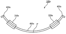
- the in-pipe purification apparatus 100e is provided with a curved member 400e penetrating through the microorganism carriers 310e and 320e. Also, fixed portions 450e are formed at both ends of the curved member 400e. As shown in FIG. 16, the in-pipe purification system 500 e is formed by providing the in-pipe purification device 100 e in the pipe 200.
- FIG. 17 is a schematic diagram showing still another example of the in-pipe purification system 500.
- the microorganism carriers 310f and 320f of the in-pipe purification device 100f are provided to each other along the extending direction of the pipe 200.
- the curved member 400f is fixed by the fixing portion 450f, and the microorganism carriers 310f and 320f are provided on the curved member 400f.
- the purification can be performed while reducing the amount of the microorganism carriers 310f and 320f.
- FIG. 18 and 19 are schematic views showing still another example of the in-pipe purification system 500 and the in-pipe purification device 100.
- FIG. 18 is a schematic diagram illustrating still another example of the in-pipe purification apparatus 100
- FIG. 19 is a schematic diagram illustrating still another example of the in-pipe purification system 500.
- a fitting portion 455g is formed below the fixed portion 450g. Moreover, as shown in FIG. 19, in the piping 200, the groove
- the in-pipe purification device 100g can be reliably fixed to the pipe 200, and the in-pipe purification system 500g can be easily formed. That is, the in-pipe purification device 100g can be easily disposed at the lowest part of the pipe 200.
- a fixed portion 450g is attached to the curved member 400g, and microorganism carriers 310g and 320g are provided at the end of the curved member 400g.
- FIG. 23 illustrates the in-pipe purification apparatuses 100 and 100 a in the in-pipe purification system 500. It is a schematic diagram for demonstrating fitting.
- the in-pipe purification apparatus 100 will be described as an example. 20 shows the front of the connecting member 700, FIG. 21 shows the side of the connecting member 700, and FIG. 22 shows the lower surface of the connecting member 700.
- connection member 700 is an elbow (L-shaped) connection member.
- the connecting member 700 includes two convex portions 711 and 712.
- the convex portions 711 and 712 are disposed on the inner side (the lowest point P side) of the microorganism carriers 310, 330a, and 320 of the in-pipe purification devices 100 and 100a provided in the pipe 200 of the in-pipe purification devices 100 and 100a. Formed to support.
- the in-pipe purification devices 100, 100a are arranged in the pipe 200, and the in-pipe purification devices 100, 100a from the outside. Even if it cannot be visually recognized, the in-pipe purification devices 100 and 100a can be easily disposed at predetermined positions of the pipe 200. Moreover, the convex parts 711 and 712 are formed so as to obtain the effect of preventing reverse insertion.
- connection member 700 can be easily fitted to the in-pipe purification device 100.
- connection member 700 was made into the elbow shape of the joint, it is not limited to this, You may consist of a socket shape, T shape (cheese shape), etc. Further, either the curved surface member 400 or the fixing portion 450 may be fixed. As a result, the outside of the microbial carriers 310, 330a, 320, and 330b can alternately come into contact with air or sewage, so that the purification action can be enhanced.
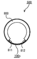
- FIG. 27 shows the in-pipe purification device in the in-pipe purification systems 500c,. It is a schematic diagram for demonstrating fitting with 100c, ..., 100g.
- the in-pipe purification apparatus 100c will be described as an example.
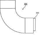
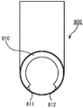
- 24 shows the front surface of the connecting member 800
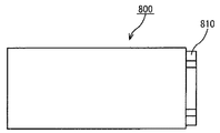
- FIG. 25 shows the side surface of the connecting member 800
- FIG. 26 shows the lower surface of the connecting member 800.
- connection member 800 has a convex portion 810.
- the convex portion 810 is formed so as to be fitted to the inner periphery of the pipe 200. That is, the convex portion 810 is formed so as to be fitted to a part of the inner periphery of the pipe 200. Further, the surfaces 811 and 812 of the convex portion 810 of the connecting member 800 are outside (the uppermost point U side) of the microorganism carriers 310c and 320c of the in-pipe purification device 100c provided in the pipe 200 in the in-pipe purification system 500c. It is formed to support.
- the connecting member 800 by disposing the connecting member 800 in the vertical direction, the in-pipe purification devices 100c,..., 100g are disposed in the pipe 200, and the in-pipe purification devices 100c,. Even in this case, the in-pipe purification devices 100c,..., 100g can be easily disposed at the lowermost part P of the pipe 200. Further, since the convex portion 810 is formed in a size other than the in-pipe purification devices 100c,..., 100g, the position of the pipe 200 can be determined uniformly. That is, the effect of preventing reverse insertion can be obtained.
- the surfaces 811 and 812 may be tapered or rounded and have a C surface. In this way, the surfaces 811 and 812 can be easily fitted with the in-pipe purification device 100c.
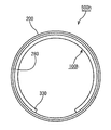
- FIG. 28 is a schematic diagram for explaining the in-pipe purification device 100h in the in-pipe purification system 500h.
- a seal hose member 280 is formed for the pipe 200, and a microorganism carrier 330 is attached to the seal hose member 280 in advance.
- the sealing hose member 280 and the microorganism carrier 330 are formed using a so-called hose lining process. Specifically, a seal hose member 280, to which a microorganism carrier 330 is attached in advance, is inserted into the pipe 200, air is fed, and the seal hose member 280 and the microorganism carrier 330 are inverted into the pipe 200 to form. To do.
- FIG. 29 is a schematic diagram for explaining the in-pipe purification device 100i in the in-pipe purification system 500i.
- microbial carriers 310 and 320 are formed instead of the microbial carrier 330.
- the in-pipe purification system 500i is formed by inverting the seal hose member 280 and the microorganism carriers 310 and 320 in the pipe 200 in the same manner as in FIG.
- the microorganism carriers 310, 330, 330a, 310, 310c, to 310g, 320, 330b, 320c, to 320g extend continuously in the longitudinal direction of the pipe 200.
- the present invention is not limited to this and may be provided intermittently.
- the microbial carriers 310, 330 a, 310 c, to 310 g and the microbial carriers 320, 330 b, 320 c, ⁇ , 320 g may be arranged in a staggered manner with respect to the extending direction of the pipe 200.
- the present invention is not limited thereto. You may arrange
- connection member 800 was made into elbow shape, it is not limited to this, You may consist of socket shape, T shape (cheese shape), etc. Further, any one of the curved surface members 400c,..., 400g or the fixing portions 450c,. As a result, the outside of the microbial carriers 310c, .about.310g, 320c,..., 320g can alternately come into contact with air or sewage, so that the purification action can be enhanced.
- the in-pipe purification apparatuses 100, 100a,..., 100i have the microorganism carriers 310, 330, 330a, 310c,..., 310g, 320, 330b, 320c,. Since they are opposed to each other across P and extend in the longitudinal direction of the pipe 200, the microorganism carriers 310, 330, 330 a, 310 c,. , 330b, 320c,..., 320g can be maintained.
- sewage WL with a low flow rate it does not come into contact with the microorganism carriers 310, 330, 330a, 310c,..., 310g, 320, 330b, 320c,.
- purification can be performed by contacting with the microorganism carriers 310, 330, 330a, 310c,..., 310g, 320, 330b, 320c,.
- the convex portions 711 and 712 and the surfaces 811 and 812 of the convex portion 810 ensure that the in-pipe purification devices 100, 100a,.
- the in-pipe purification devices 100, 100a,..., 100g can be reliably disposed at predetermined positions.
- the pipe 200 corresponds to the “pipe line”
- the in-pipe purification devices 100, 100a,..., 100i correspond to the “in-pipe purification device”
- the curved members 400, 400a correspond to the “in-pipe purification device”
- the seal hose member 280 corresponds to the “curved surface member”
- the microorganism carriers 310, 310c,..., 310g correspond to the “first microorganism carrier”
- the microorganism carriers 320, 320c .
- the microbial carriers 310, 310c,..., 310g, the microbial carriers 320, 320c,..., 320g, the microbial bodies 330, 330a, 330b correspond to the “microbe carriers”, and the lowermost part P is the “lower part”.
- the distance L1 corresponds to the “distance between the first microbial carrier and the second microbial carrier”
- the diameter R2 corresponds to the “duct diameter”
- the fixing portions 450c,..., 450g are “fixed”.
- In-pipe purification systems 500, 500a,..., 500i correspond to “in-pipe purification systems”
- connection members 700 and 800 correspond to “connection members”
- convex portions 711, 712 and The convex portion 810 corresponds to an “installation portion”.
Landscapes
- Life Sciences & Earth Sciences (AREA)
- Water Supply & Treatment (AREA)
- Hydrology & Water Resources (AREA)
- Engineering & Computer Science (AREA)
- Microbiology (AREA)
- Environmental & Geological Engineering (AREA)
- Biodiversity & Conservation Biology (AREA)
- Chemical & Material Sciences (AREA)
- Organic Chemistry (AREA)
- Health & Medical Sciences (AREA)
- Public Health (AREA)
- Biological Treatment Of Waste Water (AREA)
- Sewage (AREA)
Abstract
Description
例えば、特許文献1には、管路の内面に有用微生物群を含有したセラミック材の膜を設けることによって汚水を有用微生物と接触させ、汚水を浄化する管路用汚水浄化装置が開示されている。
また、酸素供給手段を用いる場合には、設備費、施工費が高価になる等の問題があった。さらに、管路用浄化装置は、汚水の流下性能を充分に確保し、埋設時等に生じる応力による破損を防止する必要がある。
また、特許文献4記載の管路内浄化装置および管路内浄化装置の接続構造は、高効率で汚水を浄化することができるが、構造が複雑で作業工数が多く費やされる。
一局面に従う管路内浄化装置は、管路内に設置される管路内浄化装置において、断面の少なくとも一部が管路の曲面に沿って形成された曲面状部材と、曲面状部材の少なくとも一部の周囲または内周側に、微生物担体が形成されたものである。ここで、微生物担体は、管路内に設置された場合の管路の最下部表面で欠損している。
ここで、微生物担体は、管路内に設置された場合の管路の最下部表面で欠損しているので、管路の最下部において確実に流速を確保することができる。また、流量が少ない場合には、流速を低下させることがなく、流量が多い場合には、浄化を行うことができる。
第2の発明にかかる管路内浄化装置は、一局面に従う管路内浄化装置において、曲面状部材が管路内に設置された場合の管路の最下部表面で欠損していてもよい。
第3の発明にかかる管路内浄化装置は、一局面または第2の発明にかかる管路内浄化装置において、微生物担体は、曲面状部材の両端部にそれぞれ配設される第1の微生物担体と第2の微生物担体と、を含んでもよい。
第4の発明にかかる管路内浄化装置は、一局面から第3の発明にかかる管路内に設置される管路内浄化装置において、曲面状部材に配設される第1の微生物担体と第2の微生物担体と、を含み、第1の微生物担体および第2の微生物担体は、管路内に設置された場合の曲面状部材の最下部を挟んで対向して配設されたものである。
また、流量が少ない場合には、流速を低下させることがなく、流量が多い場合には、浄化を行うことができる。
ここで、対向とは、管路に対して鉛直(管路軸が法線となる状態)のみではなく、所定の角度を有する断面において、第1の微生物担体および第2の微生物担体が対向する場合を含む。すなわち、第1の微生物担体および第2の微生物担体が管路の長手方向に沿って千鳥状態で配設される場合も含む。
第5の発明にかかる管路内浄化装置は、第4の発明にかかる管路内浄化装置において、曲面状部材は、第1の微生物担体および第2微生物担体の端部を超えて配設されてもよい。
第6の発明にかかる管路内浄化装置は、第3から第5の発明にかかる管路内浄化装置において、第1の微生物担体および第2微生物担体の距離は、曲面状部材が設置された場合の管路径の10%以上40%以下の範囲内の距離を有するように配設されてもよい。
第7の発明にかかる管路内浄化装置は、第3から第6にかかる管路内浄化装置において、第1の微生物担体および第2の微生物担体は、厚みが5mm以上50mm以下の範囲内で形成されてもよい。
第8の発明にかかる管路内浄化装置は、第3から第7の発明にかかる管路内浄化装置において、第1の微生物担体および第2の微生物担体は、幅の合計が前記管路の内周の30%以上95%以下の範囲内で形成されてもよい。
第9の発明にかかる管路内浄化装置は、第3から第8の発明にかかる管路内浄化装置において、第1の微生物担体および第2の微生物担体は、曲面状部材が設置される場合の管路の長手方向に連続して形成されてもよい。
第10の発明にかかる管路内浄化装置は、第3から第9の発明にかかる管路内浄化装置において、曲面状部材は、管路内に曲面状部材が設置された場合の管路の内周の30%以上95%以下の範囲の長さを有するように形成されてもよい。
第11の発明にかかる管路内浄化装置は、一局面から第10の発明にかかる管路内浄化装置において、曲面状部材は、管路内に配設するための位置決めを行う固定部を含んでもよい。
他の局面に従う管路内浄化システムは、管路と、断面の少なくとも一部が管路の曲面に沿って形成された曲面状部材および曲面状部材に配設される微生物担体を含む管路内浄化装置と、を含み、曲面状部材の少なくとも一部の周囲または内周側に、微生物担体が形成されており、微生物担体が、管路内に設置された場合の管路の最下部表面で欠損しているものである。
ここで、微生物担体は、管路内に設置された場合の管路の最下部表面で欠損しているので、管路の最下部において確実に流速を確保することができる。また、流量が少ない場合には、流速を低下させることがなく、流量が多い場合には、浄化を行うことができる。
第13の発明にかかる管路内浄化システムは、第12の発明にかかる管理内浄化システムにおいて、曲面状部材は、管路内に設置された場合の管路の最下部表面で欠損していてもよい。
また、流量が少ない場合には、流速を低下させることがなく、流量が多い場合には、浄化を行うことができる。
第14の発明にかかる管路内浄化システムは、他の局面または第13の発明にかかる管路内浄化システムにおいて、微生物担体は、第1の微生物担体と第2の微生物担体とを含む管路内浄化装置と、を含み、第1の微生物担体および第2の微生物担体は、曲面状部材の最下部を挟んで対向して配設されてもよい。
また、流量が少ない場合には、流速を低下させることがなく、流量が多い場合には、浄化を行うことができる。
ここで、対向とは、管路に対して鉛直(管路軸が法線となる状態)のみではなく、所定の角度を有する断面において、第1の微生物担体および第2の微生物担体が対向する場合を含む。すなわち、第1の微生物担体および第2の微生物担体が管路の長手方向に沿って千鳥状態で配設される場合も含む。
第15の発明にかかる管路内浄化システムは、他の局面から第14の発明にかかる管理内浄化システムにおいて、管路と接続される接続部材をさらに含み、接続部材は、管路内に管路内浄化装置を設置する設置部を備えてもよい。
例えば、設置部により接続部材の位置と、管路内浄化装置との相対的位置関係を調整することができる。その結果、第1の微生物担体および第2の微生物担体を曲面状部材の最下部を挟んで対向して配設させることができる。
200 配管
280 シールホース部材
310,310c,~,310g 微生物担体
320,320c,~,320g 微生物担体
330,330a,330b 微生物担体
400,400a,~,400g 曲面状部材
450c,~,450g 固定部
500,500a,~,500i 管路内浄化システム
700 接続部材
711 凸部
712 凸部
800 接続部材
810 凸部
P 最下部
U 最上部
R2 直径
図1から図3は、本実施の形態にかかる管路内浄化装置100の一例を示す模式図である。図1は管路内浄化装置100の一例を示し、図2および図3は管路内浄化装置100を配管200内に配設した管路内浄化システム500の状態を示す。
ここで、最下部Pとは、配管200の最下部に位置されるポイントを示し、最上部Uとは、配管200の最上部に位置されるポイントを示す。
また、本実施の形態における微生物担体310,320は、厚みがt1からなり、幅はL3からなる。本実施の形態においては、厚み(t1)は、5mm以上50mm以下の範囲内で形成され、微生物担体の幅(L3)の合計は、前記管路の内周の30%以上95%以下の範囲内で形成される。
そのため、上記のサイズであることが好ましい。
また、微生物担体310,320は、酸素と微生物(好気性微生物)とを効率よく接触させる必要があるため、表面積が大きく、かつ、目詰まりし難い繊維状体、発泡体、多孔質体、または網状体等を用いることが好ましい。
また、微生物担体310,320の流出防止のために、微生物担体310,320をさらに透水性の高い容器、例えば、網状体または有孔管等に封入してもよい。
なお、上記の空隙率とは、単位体積あたりにおける隙間の割合を100分率で表したものを意味する。
また、図3に示すように、管路内浄化装置100は、配管200の延在方向に沿って延在して形成される。
なお、本実施の形態においては、曲面状部材400を配管200の延在方向に沿って延在して形成されることとしているが、これに限定されず、曲面状部材400が一定距離間隔で形成されてもよい。
なお、円形でない場合には、曲面状部材400が、各内周に沿って形成される。
その結果、微生物担体310,320に、微生物(好気性微生物)が自然に付着して増殖することができ、浄化作用を働かせることができる。
次に図6から図9は、図1および図2に示した管路内浄化システム500および管路内浄化装置100の他の例を示す模式図である。
図6は管路内浄化装置100の他の例を示す模式図であり、図7は管路内浄化システム500の他の例を示す模式図である。
また、図8は、管路内浄化装置100の他の例を示す模式図であり、図9は管路内浄化システム500の他の例を示す模式図である。
次いで、図10から図12は、管路内浄化装置100の一例を示す模式図である。図10は管路内浄化装置100の他の例を示し、図11および図12は管路内浄化装置100cを配管200内に配設した管路内浄化システム500cの状態を示す。
ここで、最下部Pとは、配管200の最下部に位置されるポイントを示す。
例えば、固定部450cは、ネジ、ボルト、溶接体等である。なお、固定部450cと配管200との間を接着剤により固定してもよい。なお、その他溶接、嵌合、接着等を用いてもよい。
そのため、図10、11に示すように、固定部450cを設けなくてもよい。
また、微生物担体310c,320cは、厚みがt1からなり、幅はL3からなる。本実施の形態においては、厚み(t1)は、5mm以上50mm以下の範囲内で形成され、幅(L3)の合計は、管路の内周の30%以上95%以下の範囲内で形成される。
次に、図13および図14は、管路内浄化装置100のさらに他の例を示す模式図である。図13は管路内浄化装置100の他の例を示し、図14は管路内浄化装置100を配管200内に配設した管路内浄化システム500の他の例を示す。
以下、図10から図12の管路内浄化装置100cおよび管路内浄化システム500cと異なる点についてのみ説明する。
また、図13に示すように、曲面状部材400dは、固定部450dが形成されている。固定部450dは、管路内浄化装置100dを配管200の内周面から浮かせて固定するためのものである。
また、曲面状部材400dの曲面率を一定にしているが、これに限定されず、少なくとも一部が、配管200の内周面に沿っていればよい。
管路内浄化システム500dは、配管200内に管路内浄化装置100dを設けることにより浄化の効率を高めることができる。
図15および図16は、管路内浄化装置100のさらに他の例を示す模式図である。図15は管路内浄化装置100の他の例を示し、図16は管路内浄化装置100を配管200内に配設した管路内浄化システム500の他の例を示す。
図16に示すように、管路内浄化システム500eは、管路内浄化装置100eを配管200内に設けることで形成される。
図17は、管路内浄化システム500のさらに他の例を示す模式図である。
図18および図19は、管路内浄化システム500および管路内浄化装置100のさらに他の例を示す模式図である。図18は管路内浄化装置100のさらに他の例を示す模式図であり、図19は管路内浄化システム500のさらに他の例を示す模式図である。
また、図19に示すように、配管200においては、嵌合部455gと嵌合する溝255gが形成されている。
すなわち、配管200の最下部に管路内浄化装置100gを容易に配設することができる。
図20、図21および図22は、管路内浄化システム500における接続部材700を説明するための模式図であり、図23は、管路内浄化システム500における管路内浄化装置100,100aとの嵌合を説明するための模式図である。図23においては、管路内浄化装置100を例に挙げて説明する。
図20は、接続部材700の正面を示し、図21は、接続部材700の側面を示し、図22は、接続部材700の下面を示す。
また、凸部711,712は、逆挿防止効果を得ることができるように形成される。
その結果、微生物担体310,330a,320,330bの外側が空気または汚水に交互に接触できるので、浄化作用を高めることができる。
図24、図25および図26は、管路内浄化システム500における接続部材800を説明するための模式図であり、図27は、管路内浄化システム500c,~,500gにおける管路内浄化装置100c,~,100gとの嵌合を説明するための模式図である。図27においては、管路内浄化装置100cを例に挙げて説明する。
図24は、接続部材800の正面を示し、図25は、接続部材800の側面を示し、図26は、接続部材800の下面を示す。
すなわち、配管200の内周の一部に凸部810が嵌合するように形成される。
また、接続部材800の凸部810の面811,812は、管路内浄化システム500cにおける配管200内に設けられた管路内浄化装置100cの微生物担体310c,320cの外側(最上点U側)を支持するよう形成される。
また、凸部810は、管路内浄化装置100c,~,100g以外のサイズで形成されているため、配管200の位置は、一様に決定することができる。すなわち、逆挿防止効果を得ることができる。
このように、容易に面811,812を、管路内浄化装置100cと容易に嵌合することができる。
さらに、曲面状部材400,400a,~,400gが配管200の長手方向に沿って連続して延在する場合について説明したが、これに限定されず、配管200の長手方向に部分的に、または断続的に配設されていてもよい。
また、管路内浄化装置100,100a,~,100iが、配管200の長手方向に沿って連続して延在する場合について説明したが、これに限定されず、ユニット化して、ロケット鉛筆のように、ユニットごと押し込みつつ配管200内に連続して挿入できる形態であってもよい。
その結果、微生物担体310c,~310g,320c,~,320gの外側が空気または汚水に交互に接触できるので、浄化作用を高めることができる。
Claims (15)
- 管路内に設置される管路内浄化装置において、
断面の少なくとも一部が前記管路の曲面に沿って形成された曲面状部材と、
前記曲面状部材の少なくとも一部の周囲または内周側に、微生物担体が形成されており、
前記微生物担体が、管路内に設置された場合の管路の最下部表面で欠損している、管路内浄化装置。 - 前記曲面状部材は、管路内に設置された場合の管路の最下部表面で欠損している、請求項1記載の、管路内浄化装置。
- 前記微生物担体は、前記曲面状部材の両端部にそれぞれ配設される第1の微生物担体と第2の微生物担体と、を含む、請求項1または2記載の管路内浄化装置。
- 前記曲面状部材に配設される第1の微生物担体と第2の微生物担体と、を含み、
前記第1の微生物担体および前記第2の微生物担体は、管路内に設置された場合の前記曲面状部材の最下部を挟んで対向して配設された、請求項1乃至3のいずれか1項に記載の管路内浄化装置。 - 前記曲面状部材は、前記第1の微生物担体および前記第2微生物担体の端部を超えて配設された、請求項4記載の管路内浄化装置。
- 前記第1の微生物担体および前記第2の微生物担体の距離は、前記曲面状部材が設置された場合の管路径の10%以上40%以下の範囲内の距離を有するように配設された、請求項3から5のいずれか1項に記載の管路内浄化装置。
- 前記第1の微生物担体および前記第2の微生物担体は、厚みが5mm以上50mm以下の範囲内で形成された、請求項3から6のいずれか1項に記載の管路内浄化装置。
- 前記第1の微生物担体および前記第2の微生物担体は、幅の合計が前記管路の内周の30%以上95%以下の範囲内で形成された、請求項3から7のいずれか1項に記載の管路内浄化装置。
- 前記第1の微生物担体および前記第2の微生物担体は、前記曲面状部材が設置される場合の前記管路の長手方向に連続して形成された、請求項3から8のいずれか1項に記載の管路内浄化装置。
- 前記曲面状部材は、前記管路内に前記曲面状部材が設置された場合の前記管路の内周の30%以上95%以下の範囲の長さを有するように形成された、請求項3から9のいずれか1項に記載の管路内浄化装置。
- 前記曲面状部材は、前記管路内に配設するための位置決めを行う固定部を含む、請求項1から10のいずれか1項に記載の管路内浄化装置。
- 管路と、
断面の少なくとも一部が前記管路の曲面に 沿って形成された曲面状部材および前記曲面状部材に配設される微生物担体を含む管路内浄化装置と、を含み、
前記曲面状部材の少なくとも一部の周囲または内周側に、微生物担体が形成されており、
前記微生物担体が、管路内に設置された場合の管路の最下部表面で欠損している、管路内浄化システム。 - 前記曲面状部材は、管路内に設置された場合の管路の最下部表面で欠損している、請求項12記載の管路内浄化システム。
- 前記微生物担体は、第1の微生物担体と第2の微生物担体とを含む管路内浄化装置と、を含み、
前記第1の微生物担体および前記第2の微生物担体は、前記曲面状部材の最下部を挟んで対向して配設された、請求項12または13記載の管路内浄化システム。 - 前記管路と接続される接続部材をさらに含み、
前記接続部材は、前記管路内に前記管路内浄化装置を設置する設置部を備えた、請求項12から14に記載の管路内浄化システム。
Priority Applications (4)
| Application Number | Priority Date | Filing Date | Title |
|---|---|---|---|
| JP2016534289A JP6235718B2 (ja) | 2014-07-18 | 2015-07-17 | 管路内浄化装置および管路内浄化システム |
| AU2015291058A AU2015291058A1 (en) | 2014-07-18 | 2015-07-17 | Pipeline interior purifying apparatus, and pipeline interior purifying system |
| CN201580013897.4A CN106103356A (zh) | 2014-07-18 | 2015-07-17 | 管路内净化装置及管路内净化系统 |
| PH12016501771A PH12016501771A1 (en) | 2014-07-18 | 2016-09-08 | Pipeline interior purifying apparatus, and pipleine interior purifying system |
Applications Claiming Priority (2)
| Application Number | Priority Date | Filing Date | Title |
|---|---|---|---|
| JP2014-147784 | 2014-07-18 | ||
| JP2014147784 | 2014-07-18 |
Publications (1)
| Publication Number | Publication Date |
|---|---|
| WO2016009655A1 true WO2016009655A1 (ja) | 2016-01-21 |
Family
ID=55078161
Family Applications (1)
| Application Number | Title | Priority Date | Filing Date |
|---|---|---|---|
| PCT/JP2015/003621 Ceased WO2016009655A1 (ja) | 2014-07-18 | 2015-07-17 | 管路内浄化装置および管路内浄化システム |
Country Status (5)
| Country | Link |
|---|---|
| JP (1) | JP6235718B2 (ja) |
| CN (1) | CN106103356A (ja) |
| AU (1) | AU2015291058A1 (ja) |
| PH (1) | PH12016501771A1 (ja) |
| WO (1) | WO2016009655A1 (ja) |
Citations (1)
| Publication number | Priority date | Publication date | Assignee | Title |
|---|---|---|---|---|
| JPH07233556A (ja) * | 1992-01-28 | 1995-09-05 | Narashi | 連続空隙体が内張りされた複合管路およびその製造方法 |
Family Cites Families (5)
| Publication number | Priority date | Publication date | Assignee | Title |
|---|---|---|---|---|
| JPH0696154B2 (ja) * | 1992-11-28 | 1994-11-30 | 宏 五十嵐 | 地下埋設型浄化水路 |
| JP3825496B2 (ja) * | 1996-03-12 | 2006-09-27 | 前澤化成工業株式会社 | 嫌気性流動床排水処理方法およびその装置 |
| JP2001286882A (ja) * | 2000-04-11 | 2001-10-16 | Motoharu Tamai | 汚水水質浄化型水路 |
| EP1888846A4 (en) * | 2005-05-24 | 2014-07-09 | Presby Patent Trust | FLUID PIPING WITH MULTILAYER PARTIAL COATING MATERIAL THEREOF |
| EP2905387A4 (en) * | 2012-05-16 | 2016-05-25 | Sekisui Chemical Co Ltd | PIPING CLEANING AND CONNECTION STRUCTURE DEVICES FOR PIPING CLEANING DEVICES |
-
2015
- 2015-07-17 WO PCT/JP2015/003621 patent/WO2016009655A1/ja not_active Ceased
- 2015-07-17 CN CN201580013897.4A patent/CN106103356A/zh active Pending
- 2015-07-17 AU AU2015291058A patent/AU2015291058A1/en not_active Abandoned
- 2015-07-17 JP JP2016534289A patent/JP6235718B2/ja active Active
-
2016
- 2016-09-08 PH PH12016501771A patent/PH12016501771A1/en unknown
Patent Citations (1)
| Publication number | Priority date | Publication date | Assignee | Title |
|---|---|---|---|---|
| JPH07233556A (ja) * | 1992-01-28 | 1995-09-05 | Narashi | 連続空隙体が内張りされた複合管路およびその製造方法 |
Also Published As
| Publication number | Publication date |
|---|---|
| JPWO2016009655A1 (ja) | 2017-04-27 |
| JP6235718B2 (ja) | 2017-11-22 |
| AU2015291058A1 (en) | 2016-09-22 |
| CN106103356A (zh) | 2016-11-09 |
| PH12016501771A1 (en) | 2016-12-19 |
Similar Documents
| Publication | Publication Date | Title |
|---|---|---|
| JP6078534B2 (ja) | 管路内浄化装置、及び、管路内浄化装置の接続構造 | |
| AU2015264338B2 (en) | Modular liquid waste treatment system and method | |
| JP6235718B2 (ja) | 管路内浄化装置および管路内浄化システム | |
| CN102060390B (zh) | 污水输运管道辅助净化装置 | |
| CN102942252A (zh) | 组合式生态净化笼 | |
| US8999153B2 (en) | Liquid waste treatment system | |
| CN110546110A (zh) | 排水处理装置、隔板、排水处理装置的制造方法以及排水处理装置的区域变更方法 | |
| JP5926663B2 (ja) | 管路内浄化装置 | |
| CN202482128U (zh) | 一种生物膜载体 | |
| JP2014201891A (ja) | 管路内浄化装置 | |
| CN101571212B (zh) | 一种池中管道的固定方法 | |
| CN204400703U (zh) | 人工水草型排污口水质原位净化装置 | |
| CN202612865U (zh) | 一种不锈钢管道用管托 | |
| CN205222782U (zh) | 包埋载体拦截装置 | |
| CN205472899U (zh) | 一种生物接触氧化装置 | |
| CN205662368U (zh) | 一种箱式污水处理一体化装置 | |
| JP6037942B2 (ja) | ライニング材およびライニング複合管の形成方法 | |
| CN110451666A (zh) | 一种用于应急处理河道原位修复的反应装置 | |
| CN108187496B (zh) | 一种ehbr膜组件保护装置 | |
| CN206752429U (zh) | 一种新型木塑封闭水渠 | |
| CN112174338A (zh) | 一种悬挂式空气暴露型生物载体填料 | |
| JPH0220077Y2 (ja) | ||
| KR101149480B1 (ko) | 담체 현수장치 | |
| JP2001170669A (ja) | 好気性処理槽 | |
| CN110790375A (zh) | 排水管道源头控污多级生化处理系统 |
Legal Events
| Date | Code | Title | Description |
|---|---|---|---|
| 121 | Ep: the epo has been informed by wipo that ep was designated in this application |
Ref document number: 15821606 Country of ref document: EP Kind code of ref document: A1 |
|
| ENP | Entry into the national phase |
Ref document number: 2016534289 Country of ref document: JP Kind code of ref document: A |
|
| WWE | Wipo information: entry into national phase |
Ref document number: 12016501771 Country of ref document: PH |
|
| ENP | Entry into the national phase |
Ref document number: 2015291058 Country of ref document: AU Date of ref document: 20150717 Kind code of ref document: A |
|
| WWE | Wipo information: entry into national phase |
Ref document number: IDP00201607465 Country of ref document: ID |
|
| NENP | Non-entry into the national phase |
Ref country code: DE |
|
| 122 | Ep: pct application non-entry in european phase |
Ref document number: 15821606 Country of ref document: EP Kind code of ref document: A1 |