WO2016009510A1 - 材料試験機 - Google Patents
材料試験機 Download PDFInfo
- Publication number
- WO2016009510A1 WO2016009510A1 PCT/JP2014/068924 JP2014068924W WO2016009510A1 WO 2016009510 A1 WO2016009510 A1 WO 2016009510A1 JP 2014068924 W JP2014068924 W JP 2014068924W WO 2016009510 A1 WO2016009510 A1 WO 2016009510A1
- Authority
- WO
- WIPO (PCT)
- Prior art keywords
- strain gauge
- elastic deformation
- disposed
- input terminal
- strain
- Prior art date
- Legal status (The legal status is an assumption and is not a legal conclusion. Google has not performed a legal analysis and makes no representation as to the accuracy of the status listed.)
- Ceased
Links
Images








Classifications
-
- G—PHYSICS
- G01—MEASURING; TESTING
- G01N—INVESTIGATING OR ANALYSING MATERIALS BY DETERMINING THEIR CHEMICAL OR PHYSICAL PROPERTIES
- G01N3/00—Investigating strength properties of solid materials by application of mechanical stress
- G01N3/08—Investigating strength properties of solid materials by application of mechanical stress by applying steady tensile or compressive forces
Definitions
- This invention relates to a material testing machine using a load cell.
- a force in a direction crossing the tensile direction with respect to the test piece at the time of the tensile test
- a force in the bending direction is applied, a bending moment is applied to the test piece, which adversely affects the test result.
- the dummy test piece is gripped by the upper gripping tool and the lower gripping tool. The position of the upper gripper and the lower gripper was adjusted so that the output in the strain gauge was detected and the force in the bending direction was below a certain level.
- a drive device that adjusts the position of the lower gripper by moving the XY stage to which the lower gripper is fixed is provided, and XY based on the strain amount of the test piece measured by a strain gauge previously attached to the test piece.
- a material testing machine in which the stage is moved to correct the deviation between the axis of the test piece and the load axis direction (see Patent Document 1).
- the present invention has been made to solve the above-mentioned problems, and easily recognizes whether or not a bending direction force is applied to the test piece without using an extra dummy test piece or strain gauge.
- An object of the present invention is to provide a material testing machine capable of performing the above.
- the invention according to claim 1 is a first resistance portion disposed between the first and second input terminals, the first and second output terminals, the first input terminal and the first output terminal, A second resistor disposed between the first output terminal and the second input terminal; a third resistor disposed between the second input terminal and the second output terminal; and a second output terminal. And at least two of the first, second, third, and fourth resistor units that are not directly connected to the bridge circuit having the fourth resistor unit disposed between the first input terminal and the first resistor.
- a wiring switching mechanism for switching the arrangement of the third resistance part and the fourth resistance part in the bridge circuit It is characterized by having.
- the wiring switching mechanism includes a first resistor portion and a fourth resistor portion connected to the first input terminal, and a second resistor portion and a third resistor portion. From the state in which the resistor unit is connected to the second input terminal, the first resistor unit and the third resistor unit are connected to the first input terminal, and the second resistor unit and the fourth resistor unit are connected to the second input terminal. Switch the connection relationship of the resistor to the connected state.
- the first resistance portion includes a first strain gauge disposed on a surface of the first elastic deformation portion
- the second resistance portion includes a second strain gauge disposed on the back surface of the first elastic deformation portion
- the third resistance portion includes a third strain gauge disposed on the surface of the second elastic deformation portion
- the fourth resistance portion includes a fourth strain gauge disposed on the surface of the second elastic deformation portion.
- a material testing machine for measuring a test force using a load cell including a bridge circuit, wherein the first strain gauge disposed on the surface of the first elastically deformable portion, and the first A second strain gauge disposed on the back surface of the elastic deformation portion, a third strain gauge disposed on the surface of the second elastic deformation portion, and a fourth strain disposed on the back surface of the second elastic deformation portion.
- a gauge, the first strain gauge, and the fourth strain gauge are connected to form a first input terminal; the second strain gauge and the third strain gauge are connected to form a second input terminal; A test force measurement state in which a bridge voltage is applied between one input terminal and a second input terminal; and the first strain gauge and the third strain gauge are connected to form a first input terminal; Connect the 4th strain gauge A bridge voltage applying means for switching a bending measurement state in which a bridge voltage is applied between the first input terminal and the second input terminal, and the first strain gauge and the second strain gauge. Is connected as a first output terminal, and the third strain gauge and the fourth strain gauge are connected as a second output terminal, and a voltage between the first output terminal and the second output terminal is detected. Voltage detecting means for detecting the voltage as a voltage.
- a fifth strain gauge disposed on the surface of the third elastic deformation portion and a fifth strain gauge disposed on the back surface of the third elastic deformation portion.
- the second, third, and fourth strain gauges detect strain in the first direction
- the fifth, sixth, seventh, and eighth strain gauges are in the second direction orthogonal to the first direction.
- the first, second, third and fourth elastic deformations are connected in series with each other. Connected in series with each other a strain gauge for detecting a strain oriented mutually orthogonal directions of any of the arranged on the rear surface a strain gauge.
- a dummy test piece can be obtained by simply using a load cell that is originally arranged in the material testing machine and changing the connection relationship of the bridge circuit in the load cell. It is possible to easily recognize whether or not a force in the bending direction is applied to the test piece without using an extra strain gauge.
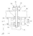
- FIG. 1 is a schematic diagram of a material testing machine according to the present invention. It is a perspective view of the test piece 10 with which a tensile test is performed with the material testing machine which concerns on this invention.
- FIG. 3 is a schematic diagram of an axis adjustment unit 13.
- FIG. 6 is a schematic plan view of the vicinity of an angle adjusting collar member in the shaft center adjusting unit. 6 is a schematic plan view of the vicinity of a position adjusting collar member 135 in the shaft center adjusting unit 13.
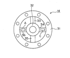
- FIG. 2 is a schematic plan view of a load cell 14.
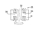
- FIG. 2 is a longitudinal sectional view of a load cell 14.
- FIG. 1 is a schematic diagram of a material testing machine according to the present invention.
- This material testing machine is for performing a tensile test on a test piece 10, and includes a base 11, a pair of left and right screw rods 12 erected on the base 11, and a pair of left and right screws. A nut portion that is screwed with the flange 12 is provided, and a crosshead 15 that is raised and lowered with respect to the screw rod 12 is provided.
- an upper gripping tool 21 is disposed via an axis adjustment mechanism 13 and a load cell 14. Further, a lower gripping tool 22 is fixed to the base 11. Both ends of the test piece 10 are gripped by the upper grip 21 and the lower grip 22.
- a synchronization pulley 17 that engages with the synchronization belt 16 is disposed at the lower end of the pair of screw rods 12.
- the synchronous belt 16 is also engaged with a synchronous pulley 18 that is rotated by driving a motor 19. For this reason, the pair of screw rods 12 rotate in synchronization with the drive of the motor 19. Then, as the pair of screw rods 12 rotate in synchronization, the cross head 15 moves up and down in the axial direction of the pair of screw rods 12.
- the test force loaded on the test piece 10 is detected by the load cell 14. Further, the displacement amount between the upper and lower gauge points of the test piece 10 is detected by a contact-type or non-contact-type displacement meter 23. Signals from the load cell 14 and the displacement meter 23 are input to a control circuit (not shown). The control circuit creates a drive control signal for the motor 19 based on signals from the load cell 14 and the displacement meter 23. Thereby, the rotation of the motor 19 is controlled, and various material tests such as a tensile test are executed.
- FIG. 2 is a perspective view of the test piece 10 on which a tensile test is executed by the material testing machine according to the present invention.
- This test piece 10 is a thin plate-like carbon fiber reinforced resin, and has a great influence on the test result when a bending direction force is applied to the X direction among the bending direction forces during the tensile test. Will occur.
- FIG. 3 is a schematic diagram of the shaft center adjustment unit 13.
- the shaft center adjusting portion 13 is interposed between the crosshead 15 and the load cell 14, and is fixed to a connecting shaft 131 that connects the crosshead 15 and the load cell 14, and a central portion of the connecting shaft 131.
- a position adjusting collar member 135 fixed to the upper gripping tool 21.
- the connecting shaft 131 passes through the angle adjusting collar member 134, the frame member 139, and the position adjusting collar member 135, and the upper end portion of the connecting shaft 131 is screwed with the mounting plate 132. Is screwed to the load cell 14.
- the mounting plate 132 is connected to the cross head 15 via a pair of jack bolts 133. For this reason, the load cell 14 can be fastened to the crosshead 15 with a predetermined force by moving the attachment plate 132 upward with respect to the crosshead 15 using the pair of jack bolts 133.
- the frame member 139 includes a support portion 137 that is screwed and fixed to the connecting shaft 131 and a rectangular frame portion 136 that surrounds the periphery of the connecting shaft 131.
- a hemispherical convex portion 138 is formed on the upper surface of the support portion 137, and a hemispherical concave portion having a shape corresponding to the convex portion 138 is formed on the lower surface of the angle adjusting collar member 134.
- the lower surface of the support portion 137 has a planar shape, and is in contact with the upper surface of the planar position adjusting collar member 135.
- FIG. 4 is a schematic plan view of the vicinity of the angle adjusting collar member 134 in the shaft center adjusting unit 13.
- the angle adjusting collar member 134 has a rectangular shape in a plan view, and an outer peripheral surface thereof is a front end portion of four screws 141, 142, 143, and 144 that are screwed with the frame portion 136 of the frame member 139. Abut. For this reason, by adjusting the four screws 141, 142, 143, and 144, the frame member 139 can be inclined together with the connecting shaft 131 to adjust the angle of the load cell 14. That is, of the four screws 141, 142, 143, 144, one of the two screws facing each other is loosened and the other is tightened, and the hemispherical convex portion 138 of the frame member 139 is moved to the angle adjusting collar member. The frame member 139 can be tilted together with the connecting shaft 131 by being moved along the hemispherical concave portion 134. As the connecting shaft 131 is inclined, the load cell 14 is inclined.
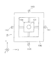
- FIG. 5 is a schematic plan view of the vicinity of the position adjusting collar member 135 in the shaft center adjusting portion 13.
- the position adjusting collar member 135 has a rectangular shape in plan view, and an outer peripheral surface thereof is a tip portion of four screws 151, 152, 153, and 154 that are screwed into the frame portion 136 of the frame member 139. Abut. For this reason, by adjusting the four screws 151, 152, 153, and 154, the position of the load cell 14 can be adjusted by moving the frame member 139 together with the connecting shaft 131. That is, of the four screws 151, 152, 153, 154, the frame member 139 is moved along the upper surface of the position adjusting collar member 135 in a state where one of the two screws facing each other is loosened and the other screw is tightened. By doing so, the frame member 139 can be moved relative to the position adjusting collar member 135 together with the connecting shaft 131. The load cell 14 moves in the X and Y directions with the relative movement of the connecting shaft 131.
- FIG. 6 is a schematic plan view of the load cell 14, and FIG. 7 is a longitudinal sectional view of the load cell 14.
- the load cell 14 includes an outer cylindrical portion 31 connected to the shaft center adjusting portion 13 side and an inner cylindrical portion 32 connected to the upper gripper 21 side, and four elastic deformation portions 33. , 34, 35, and 36.
- the outer cylindrical portion 31 and the inner cylindrical portion 32 are composed of members having rigidity.
- the four elastically deforming portions 33, 34, 35, and 36 function as displacement generating portions, and are composed of members that are more easily elastically deformed than the outer cylindrical portion 31 and the inner cylindrical portion 32.
- Yes. 7 is a longitudinal sectional view of a surface including the elastically deforming portions 34 and 36 of the load cell 14 shown in FIG.
- a strain gauge A is disposed on the surface of the elastic deformation portion 36, and a strain gauge B is disposed on the back surface. Further, a strain gauge C is disposed on the surface of the elastic deformation portion 34, and a strain gauge D is disposed on the back surface.
- These strain gauges A, B, C, and D are elastically deformable portions 34 and 36 based on changes in the distance between the inner peripheral surface of the outer cylindrical portion 31 and the outer peripheral surface of the inner cylindrical portion 32 with respect to the elastically deformable portions 34 and 36. , 36 are arranged in a direction in which expansion and contraction can be detected.
- FIG. 11 is an explanatory diagram showing a state in which the arrangement of the strain gauge C and the strain gauge D in the bridge circuit configured by the strain gauges A, B, C, and D described above is switched between the test force measurement state and the inclination detection state. .
- This bridge circuit includes a first input terminal 101, a second input terminal 102, a first output terminal 103, and a second output terminal 104.
- the bridge voltage V 0 is applied to the first input terminal 101 and the second input terminal 102, whereby the output voltage V is generated between the first output terminal 103 and the second output terminal 104. Yes.
- a strain gauge A is provided as the first resistance portion.
- the strain gauge B is arrange
- a strain gauge C is disposed as a third resistance portion.
- a strain gauge D is disposed as a fourth resistance portion.
- the first input terminal in the lower part of the arrow in FIG.
- a strain gauge A is disposed between the first output terminal 103 and the first output terminal 103 as a first resistance portion.
- the strain gauge B is arrange
- a strain gauge D is disposed as a third resistance portion.
- the strain gauge C is disposed as a fourth resistance unit.
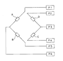
- FIG. 12 is a schematic diagram showing the wiring of the bridge circuit for executing the above-described wiring switching
- FIG. 13 is a schematic diagram of the above-described wiring switching mechanism.
- one end of the strain gauge A is connected to the terminal P1, and the other end is connected to the terminal P6.
- One end of the strain gauge B is connected to the terminal P5, and the other end is connected to the terminal P6.
- One end of the strain gauge C is connected to the terminal P3, and the other end is connected to the terminal P4.
- one end of the strain gauge D is connected to the terminal P2, and the other end is connected to the terminal P3.
- the wiring switching mechanism includes a selector switch 51 that selectively connects the terminal P4 to the terminals P1 and P5, and a switch that selectively connects the terminal P2 to the terminals P1 and P5. And a switch 52. Further, the bridge voltage V0 described above is applied between the terminal P1 and the terminal P5. Further, the voltage between the terminals P3 and P6 is detected as the output voltage V described above.
- the changeover switch 51 and the changeover switch 52 may be manually linked switches, may be contacts such as relays, or may be switched by electronic switches.
- the changeover switch 51 and the changeover switch 52 perform a changeover operation in synchronization with each other. That is, when the terminal P4 is connected to the terminal P5, the changeover switches 51 and 52 connect the terminal P2 to the terminal P1, as indicated by a solid line in FIG. In this state, this bridge circuit is in the connection state shown in the upper part of the arrow in FIG. Further, when the terminal P4 is connected to the terminal P1, the changeover switches 51 and 52 connect the terminal P2 to the terminal P5 as shown by a broken line in FIG. In this state, this bridge circuit is in the connection state shown in the lower part of the arrow in FIG.
- both ends of the test piece 10 are gripped by the upper gripping tool 21 and the lower gripping tool 22.
- the changeover switches 51 and 52 shown in FIG. 13 are in a state in which the terminal P4 and the terminal P1 indicated by the broken line in FIG. 13 are connected and the terminal P2 and the terminal P5 are connected.
- the bridge circuit is in the state shown at the bottom of the arrow in FIG.
- the load cell 14 is moved or tilted in the X and Y directions by the shaft center adjusting unit 13 shown in FIGS. 3 to 5 so that the magnitude (absolute value) of the output voltage V is not more than the set value.
- the force in the bending direction applied to the test piece 10 is set to a set value or less.
- the changeover switches 51 and 52 shown in FIG. 13 are in a state where the terminals P4 and P5 indicated by solid lines in FIG. 13 are connected and the terminals P2 and P1 are connected. In this state, the bridge circuit is in the state shown in the upper part of the arrow in FIG. By measuring the output voltage V, the tensile test force applied to the test piece 10 can be detected.
- the strain gauges A and B are disposed in the elastic deformation portion 36, and the strain gauges C and D are disposed in the elastic deformation portion 34.
- the sensitivity of detecting this force by the load cell 14 is maximized.
- the sensitivity of detecting this force by the load cell 14 is minimized. That is, when the force in the bending direction with respect to the test piece 10 becomes completely parallel to the plane including the elastic deformation portion 33 and the elastic deformation portion 35, the load cell 14 cannot detect the bending direction force. .
- the thin plate-like test piece 10 made of the thin plate-like carbon fiber reinforced resin has a test result when the bending direction force is applied to the X direction among the bending direction forces. 2 is set to a direction parallel to the plane including the elastic deformation portion 34 and the elastic deformation portion 36 (the main plane of the test piece 10 is the elastic deformation portion 33 and the elastic deformation portion). 35), it is possible to prevent adversely affecting the test result of the tensile test.
- the force in the bending direction is generated in a direction that is completely parallel to the plane including the elastic deformation portion 33 and the elastic deformation portion 35, the adverse effect on the test result is small.
- the strain gauges A and B are disposed in the elastic deformation portion 36, and the strain gauges C and D are disposed in the elastic deformation portion 34.
- the strain gauges A and C on the front side may be used, and the strain gauges B and D on the back side in the bridge circuit may be simply resistors.
- the strain gauges B and D on the back side may be used, and the strain gauges A and C on the front side in the bridge circuit may be simply resistors.
- at least two resistance portions that are not directly connected (not arranged next to each other) in a normal bridge circuit that detects a tensile force may be strain gauges.
- FIG. 14 is a schematic plan view of the load cell 14 according to the second embodiment
- FIGS. 15 and 16 are longitudinal sectional views of the load cell 14.
- FIG. 15 is a longitudinal sectional view of a surface including the elastic deformation portions 34 and 36
- FIG. 16 is a longitudinal sectional view of a surface including the elastic deformation portions 33 and 35.
- symbol is attached
- the strain gauge E is disposed on the surface of the elastic deformation portion 36, and the strain gauge F is disposed on the back surface. Further, a strain gauge G is disposed on the surface of the elastic deformation portion 34, and a strain gauge H is disposed on the back surface. A strain gauge I is disposed on the surface of the elastically deforming portion 33, and a strain gauge J is disposed on the back surface. Furthermore, a strain gauge K is disposed on the surface of the elastic deformation portion 35, and a strain gauge L is disposed on the back surface.
- strain gauges E, F, G, H, I, J, K, and L are distances between the inner peripheral surface of the outer cylindrical portion 31 and the outer peripheral surface of the inner cylindrical portion 32 with respect to the elastically deformable portions 34 and 36.
- the elastic deformation portions 34 and 36 are arranged in a direction in which the expansion and contraction of the elastic deformation portions 34 and 36 can be detected.
- FIG. 17 is a schematic diagram showing wiring of a bridge circuit for executing wiring switching. This bridge circuit is connected to the wiring switching mechanism shown in FIG. In addition, about the member similar to FIG. 12 mentioned above, the same code
- the inner cylindrical portion 32 is lowered with respect to the outer cylindrical portion 31.
- the surface of the elastic deformation part 36 in which the strain gauge E is disposed the surface of the elastic deformation part 34 in which the strain gauge G is disposed, the surface of the elastic deformation part 33 in which the strain gauge I is disposed, and the strain gauge.
- the surface of the elastic deformation portion 35 provided with K is elongated, the back surface of the elastic deformation portion 36 provided with the strain gauge F, the back surface of the elastic deformation portion 34 provided with the strain gauge H, the strain gauge. Shrinkage occurs on the back surface of the elastic deformation portion 33 provided with J and the back surface of the elastic deformation portion 35 provided with the strain gauge L.
- the test piece 10 is switched by switching the arrangement of the strain gauges H and J arranged in series with each other and the strain gauges G and K arranged in series with each other.
- the structure which recognizes whether the force of a bending direction is provided to the test piece 10 with the tensile test force provided to is applied.
- strain gauges E, F, and G that detect strain directed in a direction (first direction) parallel to a plane including the elastic deformation portion 34 and the elastic deformation portion 36.
- H, and strain gauges I, J, K, and L that detect strains in a direction parallel to a plane including the elastic deformation portion 33 and the elastic deformation portion 35 (second direction orthogonal to the first direction), Therefore, the load cell 14 can detect any bending force generated in the test piece 10 in any direction.
- the arrangement of the strain gauges E, F, G, H, I, J, K, and L in the bridge circuit may be the arrangement shown in FIGS. 18 and 19 as well as the arrangement shown in FIG. Even in such an arrangement, both the test force and the force in the bending direction can be detected as in the embodiment shown in FIG.
Landscapes
- Physics & Mathematics (AREA)
- Health & Medical Sciences (AREA)
- Life Sciences & Earth Sciences (AREA)
- Chemical & Material Sciences (AREA)
- Analytical Chemistry (AREA)
- Biochemistry (AREA)
- General Health & Medical Sciences (AREA)
- General Physics & Mathematics (AREA)
- Immunology (AREA)
- Pathology (AREA)
- Investigating Strength Of Materials By Application Of Mechanical Stress (AREA)
Abstract
試験力測定状態においては、第1入力端子101と第1出力端子103との間にはひずみゲージAが配設され、第1出力端子101と第2入力端子102との間にはひずみゲージBが配設され、第2入力端子102と第2出力端子104との間にはひずみゲージCが配設され、第2出力端子104と第1入力端子101との間にはひずみゲージDが配設される。曲げ測定状態においては、配線切替機構の作用により、ブリッジ回路におけるひずみゲージCとひずみゲージDの接続関係を切り替える。
Description
この発明は、ロードセルを使用した材料試験機に関する。
例えば、炭素繊維強化樹脂などのように脆性的な破壊挙動を示す材料から成る試験片に対して引張試験を行う場合に、引張試験時に試験片に対して引張方向と交差する方向に向かう力(曲げ方向の力)が付与された場合には、試験片に曲げモーメントを与えることになることから、試験結果に悪影響を与える。このため、従来においては、ダミーの試験片に対して曲げ方向の力を検出する方向にひずみゲージを取り付けた後、このダミーの試験片を上つかみ具と下つかみ具により把持し、このときのひずみゲージの出力を検出して曲げ方向の力が一定以下となるように、上つかみ具と下つかみ具の位置を調整していた。
また、下つかみ具を固定したXYステージを移動することで下つかみ具の位置を調整する駆動装置を設け、試験片に予め取り付けておいたひずみゲージにより測定した試験片のひずみ量に基づいてXYステージを移動させることにより、試験片の軸心と負荷軸方向のずれを補正するようにした材料試験機も提案されている(特許文献1参照)。
上述したように、ダミーの試験片を使用して上つかみ具の位置と下つかみ具の位置とを調整する場合には、試験開始前の前準備として位置合わせを行っているに過ぎず、実際に試験を行う試験片を把持した状態で調整を行っているわけではないことから、試験を行う試験片の装着時には試験片に対して曲げ方向の力が付与される可能性がある。
また、ひずみゲージを使用して曲げ方向の力を測定する場合には、ひずみゲージが消耗品として使用されることになり、ランニングコストが上昇する。これは、特許文献1に記載された材料試験機の場合も同様である。
この発明は上記課題を解決するためになされたものであり、ダミーの試験片やひずみゲージを余分に使用することなく、試験片に曲げ方向の力が付与されているか否かを容易に認識することが可能な材料試験機を提供することを目的とする。
請求項1に記載の発明は、第1、第2入力端子と、第1、第2出力端子と、第1入力端子と第1出力端子との間に配設された第1抵抗部と、第1出力端子と第2入力端子との間に配設された第2抵抗部と、第2入力端子と第2出力端子との間に配設された第3抵抗部と、第2出力端子と第1入力端子との間に配設された第4抵抗部とを有するブリッジ回路に対して、第1、第2、第3、第4抵抗部のうちの直接接続されない少なくとも二箇所の抵抗部を、弾性変形部に配設された一対のひずみゲージとしたロードセルを備えた材料試験機において、前記ブリッジ回路における前記第3抵抗部と前記第4抵抗部との配置を切り替える配線切替機構を備えたことを特徴とする。
請求項2に記載の発明は、請求項1に記載の発明において、前記配線切替機構は、第1抵抗部と第4抵抗部とが第1入力端子に接続され、第2抵抗部と第3抵抗部とが第2入力端子に接続された状態から、第1抵抗部と第3抵抗部とが第1入力端子に接続され、第2抵抗部と第4抵抗部とが第2入力端子に接続された状態に抵抗部の接続関係を切り替える。
請求項3に記載の発明は、請求項1または請求項2に記載の発明において、前記第1抵抗部は、第1弾性変形部の表面に配設された第1ひずみゲージから構成され、前記第2抵抗部は、第1弾性変形部の裏面に配設された第2ひずみゲージから構成され、前記第3抵抗部は、第2弾性変形部の表面に配設された第3ひずみゲージから構成され、前記第4抵抗部は、第2弾性変形部の表面に配設された第4ひずみゲージから構成される。
請求項4に記載の発明は、ブリッジ回路を備えたロードセルを利用して試験力を測定する材料試験機において、第1弾性変形部の表面に配設された第1ひずみゲージと、前記第1弾性変形部の裏面に配設された第2ひずみゲージと、第2弾性変形部の表面に配設された第3ひずみゲージと、前記第2弾性変形部の裏面に配設された第4ひずみゲージと、前記第1ひずみゲージと前記第4ひずみゲージとを接続して第1入力端子とし、前記第2ひずみゲージと前記第3ひずみゲージとを接続して第2入力端子とし、これらの第1入力端子と第2入力端子の間にブリッジ電圧を付与する試験力測定状態と、前記第1ひずみゲージと前記第3ひずみゲージとを接続して第1入力端子とし、前記第2ひずみゲージと前記第4ひずみゲージとを接続して第2入力端子とし、これらの第1入力端子と第2入力端子の間にブリッジ電圧を付与する曲げ測定状態と、を切り替えるブリッジ電圧付与手段と、前記第1ひずみゲージと前記第2ひずみゲージとを接続して第1出力端子とし、前記第3ひずみゲージと前記第4ひずみゲージとを接続して第2出力端子とし、前記第1出力端子と前記第2出力端子との間の電圧を検出電圧として検出する電圧検出手段と、を備えたことを特徴とする。
請求項5に記載の発明は、請求項4に記載の発明において、第3弾性変形部の表面に配設された第5ひずみゲージと、前記第3弾性変形部の裏面に配設された第6ひずみゲージと、第4弾性変形部の表面に配設された第7ひずみゲージと、前記第4弾性変形部の裏面に配設された第8ひずみゲージと、をさらに備え、前記第1、第2、第3、第4ひずみゲージは第1の方向を向くひずみを検出するとともに、前記第5、第6、第7、第8ひずみゲージは前記第1の方向と直交する第2の方向を向くひずみを検出し、前記第1、第2、第3、第4弾性変形部のいずれかの表面に配設されたひずみゲージのうちの互いに直交する方向を向くひずみを検出するひずみゲージを互いに直列に接続するとともに、前記第1、第2、第3、第4弾性変形部のいずれかの裏面に配設されたひずみゲージのうちの互いに直交する方向を向くひずみを検出するひずみゲージを互いに直列に接続する。
請求項1から請求項5に記載の発明によれば、材料試験機に、本来、配設されているロードセルを利用し、このロードセルにおけるブリッジ回路の接続関係を変更するだけで、ダミーの試験片やひずみゲージを余分に使用することなく、試験片に曲げ方向の力が付与されているか否かを容易に認識することが可能となる。
以下、この発明の実施の形態を図面に基づいて説明する。図1は、この発明に係る材料試験機の概要図である。
この材料試験機は、試験片10に対して引張試験を実行するためのものであり、基台11と、この基台11上に立設された左右一対のねじ棹12と、左右一対のねじ棹12と螺合するナット部を備え、ねじ棹12に対して昇降するクロスヘッド15とを備える。クロスヘッド15には、上つかみ具21が、軸心調整機構13およびロードセル14を介して配設されている。また、基台11には下つかみ具22が固定されている。試験片10は、その両端をこれらの上つかみ具21および下つかみ具22により把持される。
一対のねじ棹12の下端部には、各々、同期ベルト16と係合する同期プーリー17が配設されている。また、この同期ベルト16は、モータ19の駆動により回転する同期プーリー18とも係合している。このため、一対のねじ棹12は、モータ19の駆動により同期して回転する。そして、一対のねじ棹12が同期して回転することにより、クロスヘッド15は、一対のねじ棹12の軸心方向に昇降する。
試験片10に負荷される試験力は、ロードセル14により検出される。また、試験片10の上下の標点間の変位量は、接触方式または非接触方式の変位計23により検出される。ロードセル14および変位計23からの信号は図示しない制御回路に入力される。この制御回路は、ロードセル14および変位計23からの信号に基づいて、モータ19の駆動制御信号を作成する。これにより、モータ19の回転が制御され、引張試験等の各種材料試験が実行される。
図2は、この発明に係る材料試験機により引張試験が実行される試験片10の斜視図である。この試験片10は、薄板状の炭素繊維強化樹脂であり、引張試験時に、曲げ方向の力のうち、特に、X方向に対して曲げ方向の力が付与された場合に、試験結果に大きな影響が生ずることになる。
図3は、軸心調整部13の概要図である。
この軸心調整部13は、クロスヘッド15とロードセル14との間に介在されるものであり、クロスヘッド15とロードセル14とを連結する連結軸131と、この連結軸131の中央部に固定された枠部材139と、枠部材139の内部で連結軸131の外周部に配設され、クロスヘッド15に固定された角度調整用カラー部材134と、枠部材139の内部で連結軸131の外周部に配設され、上つかみ具21に固定された位置調整用カラー部材135とを備える。
連結軸131は、角度調整用カラー部材134、枠部材139および位置調整用カラー部材135を貫通するとともに、連結軸131の上端部は取付板132と螺合しており、連結軸131の下端部はロードセル14と螺合している。また、取付板132は、一対のジャッキボルト133を介してクロスヘッド15と連結されている。このため、一対のジャッキボルト133を利用して取付板132をクロスヘッド15に対して上方に移動させることにより、ロードセル14を所定の力でクロスヘッド15に対して締結することができる。
枠部材139は、連結軸131に螺合して固定された支持部137と、連結軸131の周囲を囲う矩形状の枠部136とから構成される。支持部137の上面には、半球状の凸部138が形成されており、角度調整用カラー部材134の下面にはこの凸部138と対応する形状を有する半球状の凹部が形成されている。また、支持部137の下面は平面状となっており、平面状の位置調整用カラー部材135の上面と当接している。
図4は、軸心調整部13における角度調整用カラー部材134付近の平面概要図である。
この角度調整用カラー部材134は、平面視において矩形状の形状を有し、その外周面は、枠部材139における枠部136と螺合する4本のネジ141、142、143、144の先端部と当接している。このため、4本のネジ141、142、143、144を調整することにより、枠部材139を連結軸131とともに傾斜させてロードセル14の角度を調整することが可能となる。すなわち、4本のネジ141、142、143、144のうち、互いに対向する2本のネジの一方を緩め一方を締めた状態で、枠部材139の半球状の凸部138を角度調整用カラー部材134の半球状の凹部に沿って移動させることにより、枠部材139を連結軸131とともに傾斜させることが可能となる。そして、この連結軸131の傾斜に伴って、ロードセル14が傾斜する。
図5は、軸心調整部13における位置調整用カラー部材135付近の平面概要図である。
この位置調整用カラー部材135は、平面視において矩形状の形状を有し、その外周面は、枠部材139における枠部136と螺合する4本のネジ151、152、153、154の先端部と当接している。このため、4本のネジ151、152、153、154を調整することにより、枠部材139を連結軸131とともに移動させてロードセル14の位置を調整することが可能となる。すなわち、4本のネジ151、152、153、154のうち、互いに対向する2本のネジの一方を緩め一方を締めた状態で、枠部材139を位置調整用カラー部材135の上面に沿って移動させることにより、枠部材139を連結軸131とともに位置調整用カラー部材135に対して相対的に移動させることが可能となる。そして、この連結軸131の相対的な移動に伴って、ロードセル14がX、Y方向に移動する。
図6は、ロードセル14の平面概要図であり、図7は、ロードセル14の縦断面図である。
これらの図に示すように、ロードセル14は、軸心調整部13側に連結される外円筒部31と上つかみ具21側に連結される内円筒部32とを、4個の弾性変形部33、34、35、36により連結した構成を有する。外円筒部31と内円筒部32とは、剛性を有する部材から構成されている。一方、4個の弾性変形部33、34、35、36は、変位発生部として機能するものであり、外円筒部31および内円筒部32と比較して、弾性変形し易い部材から構成されている。なお、図7は、図6に示すロードセル14の弾性変形部34、36を含む面の縦断面図となっている。
弾性変形部36の表面にはひずみゲージAが配設されており、裏面にはひずみゲージBが配設されている。また、弾性変形部34の表面にはひずみゲージCが配設されており、裏面にはひずみゲージDが配設されている。これらのひずみゲージA、B、C、Dは、弾性変形部34,36に対して、外円筒部31の内周面と内円筒部32の外周面との距離の変化に基づく弾性変形部34、36の伸びおよび縮みを検出可能な方向に配設されている。
図8から図10は、ロードセル14の変形を示す説明図である。
試験片10に対して引張力が付与されておらず、ロードセル14に対して力が付与されていない場合には、図8に示すように、ロードセル14における4個の弾性変形部33、34、35、36は変形していない。
図9において矢印で示すように、試験片10に引張力が付与され、ロードセル14に対して試験力方向の力が付与された場合には、内円筒部32が外円筒部31に対して下降することになる。これにより、ひずみゲージAが配設された弾性変形部36の表面には伸びが、ひずみゲージBが配設された弾性変形部36の裏面には縮みが生ずることになる。また、ひずみゲージCが配設された弾性変形部34の表面には伸びが、ひずみゲージDが配設された弾性変形部34の裏面には縮みが生ずることになる。
一方、図10において矢印で示すように、試験片10に曲げ方向の力が付与され、これによりロードセル14に曲げ方向の力が付与された場合には、内円筒部32の軸心が外円筒部31に対して傾斜することになる。これにより、ひずみゲージAが配設された弾性変形部36の表面には伸びが、ひずみゲージBが配設された弾性変形部36の裏面には縮みが生ずることになる。また、ひずみゲージCが配設された弾性変形部34の表面には縮みが、ひずみゲージDが配設された弾性変形部34の裏面には伸びが生ずることになる。
このため、この発明に係る材料試験機においては、このひずみゲージC,Dの伸びと縮みが入れ替わることを利用して、試験片10に曲げ方向の力が付与されているか否かを認識する構成を採用している。
図11は、上述したひずみゲージA、B、C、Dにより構成されたブリッジ回路におけるひずみゲージCおよびひずみゲージDの配置を、試験力測定状態と傾き検出状態で切り替える様子を示す説明図である。
このブリッジ回路は、第1入力端子101と、第2入力端子102と、第1出力端子103と、第2出力端子104とを備える。そして、第1入力端子101と第2入力端子102に対してブリッジ電圧V0が付与されることにより、第1出力端子103と第2出力端子104との間に出力電圧Vが生ずる構成となっている。
このブリッジ回路においては、引張試験時の試験力を測定する試験力測定状態においては、図11において矢印の上部に示すように、第1入力端子101と第1出力端子103との間には、ひずみゲージAが、第1抵抗部として配設されている。第1出力端子101と第2入力端子102との間には、ひずみゲージBが、第2抵抗部として配設されている。第2入力端子102と第2出力端子104との間には、ひずみゲージCが、第3抵抗部として配設されている。第2出力端子104と第1入力端子101との間には、ひずみゲージDが、第4抵抗部として配設されている。
この状態において、図9において矢印で示すように、試験片10に引張力が付与された場合には、ひずみゲージAが配設された弾性変形部36の表面に伸びが生ずることによりひずみゲージAの抵抗値が増加し、ひずみゲージBが配設された弾性変形部36の裏面に縮みが生ずることからひずみゲージBの抵抗値が減少し、ひずみゲージCが配設された弾性変形部34の表面に伸びが生ずることからひずみゲージCの抵抗値が増加し、ひずみゲージDが配設された弾性変形部34の裏面に縮みが生ずることからひずみゲージDの抵抗値が減少する。これにより、出力電圧Vに変化が生じ、出力電圧Vを測定することにより、試験片10に付与された試験力を検出することが可能となる。
一方、このブリッジ回路においては、試験片10に生ずる曲げ方向の力を測定する曲げ測定状態においては、後述する配線切替機構の作用により、図11において矢印の下部に示すように、第1入力端子101と第1出力端子103との間には、ひずみゲージAが、第1抵抗部として配設される。第1出力端子101と第2入力端子102との間には、ひずみゲージBが、第2抵抗部として配設される。第2入力端子102と第2出力端子104との間には、ひずみゲージDが、第3抵抗部として配設される。第2出力端子104と第1入力端子101との間には、ひずみゲージCが、第4抵抗部として配設される。
この状態において、図10において矢印で示すように、試験片10に曲げ方向の力が付与された場合には、ひずみゲージAが配設された弾性変形部36の表面に伸びが生ずることによりひずみゲージAの抵抗値が増加し、ひずみゲージBが配設された弾性変形部36の裏面に縮みが生ずることからひずみゲージBの抵抗値が減少し、ひずみゲージCが配設された弾性変形部34の表面に縮みが生ずることからひずみゲージCの抵抗値が減少し、ひずみゲージDが配設された弾性変形部34の裏面に伸びが生ずることからひずみゲージDの抵抗値が増加する。これにより、出力電圧Vに変化が生じ、出力電圧Vを測定することにより、試験片10に付与された曲げ方向の力を検出することが可能となる。
図12は、上述した配線の切替を実行するためのブリッジ回路の配線を示す概要図であり、図13は、上述した配線切替機構の概要図である。
図12に示すように、ひずみゲージAの一端は端子P1に接続されており、他端は端子P6に接続されている。また、ひずみゲージBの一端は端子P5に接続されており、他端は端子P6に接続されている。また、ひずみゲージCの一端は端子P3に接続されており、他端は端子P4に接続されている。さらに、ひずみゲージDの一端は端子P2に接続されており、他端は端子P3に接続されている。
図13に示すように、配線切替機構は、端子P4を、端子P1と端子P5とに選択的に接続する切替スイッチ51と、端子P2を、端子P1と端子P5とに選択的に接続する切替スイッチ52とを備える。また、端子P1と端子P5との間には、上述したブリッジ電圧V0が付与される。また、端子P3と端子P6の間の電圧は、上述した出力電圧Vとして検出される。切替スイッチ51と切替スイッチ52は手動の連動スイッチでもよいし、リレーなどの接点でもよく、さらには電子的なスイッチで切り替えるようにしてもよい。
切替スイッチ51と切替スイッチ52とは、互いに同期して切替動作を行う。すなわち、切替スイッチ51、52は、端子P4が端子P5に接続されたときには、図13において実線で示すように、端子P2を端子P1に接続する。この状態においては、このブリッジ回路は、図11において矢印の上部に示す接続状態となる。また、切替スイッチ51、52は、端子P4が端子P1に接続されたときには、図13において破線で示すように、端子P2を端子P5に接続する。この状態においては、このブリッジ回路は、図11において矢印の下部に示す接続状態となる。
次に、上述したロードセルを備えた材料試験機により試験片10の引張試験を実行するときの動作について説明する。
引張試験を実行するときには、試験片10の両端を上つかみ具21と下つかみ具22により把持する。この状態において、図13に示す切替スイッチ51、52を、図13において破線で示す端子P4と端子P1とが接続され、端子P2と端子P5とが接続された状態とする。この状態においては、ブリッジ回路は、図11において矢印の下部に示す状態となる。このときには、出力電圧Vを測定することにより、試験片10に付与された曲げ方向の力を検出することが可能となる。そして、出力電圧Vの大きさ(絶対値)が設定値以下となるように、図3から図5に示す軸心調整部13により、ロードセル14をX、Y方向に移動させ、あるいは,傾斜させることにより、試験片10に付与される曲げ方向の力を設定値以下とする。
試験片10に付与される曲げ方向の力が設定値以下となれば、引き続き、引張試験を開始する。このときには、図13に示す切替スイッチ51、52を、図13において実線で示す端子P4と端子P5とが接続され、端子P2と端子P1とが接続された状態とする。この状態においては、ブリッジ回路は、図11において矢印の上部に示す状態となる。出力電圧Vを測定することにより、試験片10に付与された引張試験力を検出することが可能となる。
なお、上述した実施形態においては、弾性変形部36にひずみゲージA、Bを配設し、弾性変形部34にひずみゲージC、Dを配設している。このため、試験片10に対する曲げ方向の力が弾性変形部34と弾性変形部36とを含む平面と平行な方向で発生したときに、ロードセル14によりこの力を検出する感度が最大となり、試験片10に対する曲げ方向の力が弾性変形部33と弾性変形部35とを含む平面と平行な方向で発生したときに、ロードセル14によりこの力を検出する感度が最小となる。すなわち、試験片10に対する曲げ方向の力が、弾性変形部33と弾性変形部35とを含む平面と完全に平行となった場合には、ロードセル14によりこの曲げ方向の力を検出できないことになる。
しかしながら、上述したように、薄板状の炭素繊維強化樹脂から成る薄板状の試験片10は、曲げ方向の力のうち、特に、X方向に対して曲げ方向の力が付与された場合に試験結果に大きな影響が生ずることから、図2に示すX方向を弾性変形部34と弾性変形部36とを含む平面と平行な方向とする(試験片10における主平面を弾性変形部33と弾性変形部35とを含む平面と平行な方向とする)ことにより、引張試験の試験結果に悪影響を与えることを防止することが可能となる。曲げ方向の力が弾性変形部33と弾性変形部35とを含む平面と完全に平行となる方向で発生した場合においては、試験結果への悪影響は小さい。
また、上述した実施形態においては、弾性変形部36にひずみゲージA、Bを配設し、弾性変形部34にひずみゲージC、Dを配設している。しかしながら、表側のひずみゲージA、Cのみを利用し、ブリッジ回路における裏側のひずみゲージB、Dを単なる抵抗としてもよい。同様に、裏側のひずみゲージB、Dのみを利用し、ブリッジ回路における表側のひずみゲージA、Cを単なる抵抗としてもよい。要するに、引張力を検出する通常のブリッジ回路において直接接続されない(隣同士に配置されない)少なくとも二つの抵抗部分がひずみゲージであればよい。
次に、この発明の他の実施形態について説明する。図14は、第2実施形態に係るロードセル14の平面概要図であり、図15および図16は、ロードセル14の縦断面図である。ここで、図15は、弾性変形部34、36を含む面の縦断面図であり、図16は、弾性変形部33、35を含む面の縦断面図である。なお、図6および図7に示す実施形態と同様の部材については、同一の符号を付して詳細な説明を省略する。
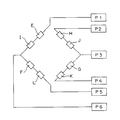
この第2実施形態に係るロードセル14においては、弾性変形部36の表面にはひずみゲージEが配設されており、裏面にはひずみゲージFが配設されている。また、弾性変形部34の表面にはひずみゲージGが配設されており、裏面にはひずみゲージHが配設されている。また、弾性変形部33の表面にはひずみゲージIが配設されており、裏面にはひずみゲージJが配設されている。さらに、弾性変形部35の表面にはひずみゲージKが配設されており、裏面にはひずみゲージLが配設されている。これらのひずみゲージE、F、G、H、I、J、K、Lは、弾性変形部34,36に対して、外円筒部31の内周面と内円筒部32の外周面との距離の変化に基づく弾性変形部34、36の伸びおよび縮みを検出可能な方向に配設されている。
図17は、配線の切替を実行するためのブリッジ回路の配線を示す概要図である。このブリッジ回路は、図13に示す配線切替機構と接続されている。なお、上述した図12と同様の部材については、同一の符号を付して詳細な説明を省略する。
このロードセル14においては、試験片10に引張力が付与され、ロードセル14に対して試験力方向の力が付与された場合には、内円筒部32が外円筒部31に対して下降することになる。これにより、ひずみゲージEが配設された弾性変形部36の表面、ひずみゲージGが配設された弾性変形部34の表面、ひずみゲージIが配設された弾性変形部33の表面およびひずみゲージKが配設された弾性変形部35の表面には伸びが生じ、ひずみゲージFが配設された弾性変形部36の裏面、ひずみゲージHが配設された弾性変形部34の裏面、ひずみゲージJが配設された弾性変形部33の裏面およびひずみゲージLが配設された弾性変形部35の裏面には縮みが生じることになる。
一方、試験片10に曲げ方向の力が付与され、これによりロードセル14に曲げ方向の力が付与された場合には、内円筒部32の軸心が外円筒部31に対して傾斜することになる。これにより、表面側のひずみゲージE、G、I、Kの一部には伸びが生じ、一部には縮みが生ずる。同様に、裏面側のひずみゲージF、H、J、Lの一部には伸びが生じ、一部には縮みが生ずる。
このため、この実施形態に係るロードセル14においては、互いに直列に配設されたひずみゲージH、Jと、互いに直列に配設されたひずみゲージG、Kとの配置を切り替えることにより、試験片10に付与される引張試験力とともに、試験片10に曲げ方向の力が付与されているか否かを認識する構成を採用している。
また、この第2実施形態に係るロードセル14においては、 弾性変形部34と弾性変形部36とを含む平面と平行な方向(第1の方向)を向くひずみを検出するひずみゲージE、F、G、Hと、弾性変形部33と弾性変形部35とを含む平面と平行な方向(第1の方向と直交する第2の方向)を向くひずみを検出するひずみゲージI、J、K、Lとを配設していることから、試験片10に曲げ方向の力がいかなる方向に生じた場合であってもロードセル14によりこれを検出することが可能となる。
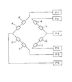
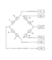
なお、ブリッジ回路中のひずみゲージE、F、G、H、I、J、K、Lの配置は、図17に示す配置だけではなく、図18および図19に示す配置としてもよい。このような配置とした場合においても、図17に示す実施形態同様、試験力と曲げ方向の力の両方を検出することが可能となる。
10 試験片
11 基台
12 ねじ棹
13 軸心調整機構
14 ロードセル
15 クロスヘッド
21 上つかみ具
22 下つかみ具
23 変位計
31 外円筒部
32 内円筒部
33 弾性変形部
34 弾性変形部
35 弾性変形部
36 弾性変形部
51 切替スイッチ
52 切替スイッチ
101 第1入力端子
102 第2入力端子
103 第3入力端子
104 第4入力端子
A~L ひずみゲージ
V 出力電圧
V0 ブリッジ電圧
11 基台
12 ねじ棹
13 軸心調整機構
14 ロードセル
15 クロスヘッド
21 上つかみ具
22 下つかみ具
23 変位計
31 外円筒部
32 内円筒部
33 弾性変形部
34 弾性変形部
35 弾性変形部
36 弾性変形部
51 切替スイッチ
52 切替スイッチ
101 第1入力端子
102 第2入力端子
103 第3入力端子
104 第4入力端子
A~L ひずみゲージ
V 出力電圧
V0 ブリッジ電圧
Claims (5)
- 第1、第2入力端子と、第1、第2出力端子と、第1入力端子と第1出力端子との間に配設された第1抵抗部と、第1出力端子と第2入力端子との間に配設された第2抵抗部と、第2入力端子と第2出力端子との間に配設された第3抵抗部と、第2出力端子と第1入力端子との間に配設された第4抵抗部とを有するブリッジ回路に対して、第1、第2、第3、第4抵抗部のうちの直接接続されない少なくとも二箇所の抵抗部を、弾性変形部に配設された一対のひずみゲージとしたロードセルを備えた材料試験機において、
前記ブリッジ回路における前記第3抵抗部と前記第4抵抗部との配置を切り替える配線切替機構を備えたことを特徴とする材料試験機。 - 請求項1に記載の材料試験機において、
前記配線切替機構は、第1抵抗部と第4抵抗部とが第1入力端子に接続され、第2抵抗部と第3抵抗部とが第2入力端子に接続された状態から、
第1抵抗部と第3抵抗部とが第1入力端子に接続され、第2抵抗部と第4抵抗部とが第2入力端子に接続された状態に抵抗部の接続関係を切り替える材料試験機。 - 請求項1または請求項2に記載の材料試験機において、
前記第1抵抗部は、第1弾性変形部の表面に配設された第1ひずみゲージから構成され、
前記第2抵抗部は、第1弾性変形部の裏面に配設された第2ひずみゲージから構成され、
前記第3抵抗部は、第2弾性変形部の表面に配設された第3ひずみゲージから構成され、
前記第4抵抗部は、第2弾性変形部の表面に配設された第4ひずみゲージから構成される材料試験機。 - ブリッジ回路を備えたロードセルを利用して試験力を測定する材料試験機において、
第1弾性変形部の表面に配設された第1ひずみゲージと、
前記第1弾性変形部の裏面に配設された第2ひずみゲージと、
第2弾性変形部の表面に配設された第3ひずみゲージと、
前記第2弾性変形部の裏面に配設された第4ひずみゲージと、
前記第1ひずみゲージと前記第4ひずみゲージとを接続して第1入力端子とし、前記第2ひずみゲージと前記第3ひずみゲージとを接続して第2入力端子とし、これらの第1入力端子と第2入力端子の間にブリッジ電圧を付与する試験力測定状態と、前記第1ひずみゲージと前記第3ひずみゲージとを接続して第1入力端子とし、前記第2ひずみゲージと前記第4ひずみゲージとを接続して第2入力端子とし、これらの第1入力端子と第2入力端子の間にブリッジ電圧を付与する曲げ測定状態と、を切り替えるブリッジ電圧付与手段と、
前記第1ひずみゲージと前記第2ひずみゲージとを接続して第1出力端子とし、前記第3ひずみゲージと前記第4ひずみゲージとを接続して第2出力端子とし、前記第1出力端子と前記第2出力端子との間の電圧を検出電圧として検出する電圧検出手段と、
を備えたことを特徴とする材料試験機。 - 請求項4に記載の材料試験機において、
第3弾性変形部の表面に配設された第5ひずみゲージと、
前記第3弾性変形部の裏面に配設された第6ひずみゲージと、
第4弾性変形部の表面に配設された第7ひずみゲージと、
前記第4弾性変形部の裏面に配設された第8ひずみゲージと、
をさらに備え、
前記第1、第2、第3、第4ひずみゲージは第1の方向を向くひずみを検出するとともに、前記第5、第6、第7、第8ひずみゲージは前記第1の方向と直交する第2の方向を向くひずみを検出し、
前記第1、第2、第3、第4弾性変形部のいずれかの表面に配設されたひずみゲージのうちの互いに直交する方向を向くひずみを検出するひずみゲージを互いに直列に接続するとともに、
前記第1、第2、第3、第4弾性変形部のいずれかの裏面に配設されたひずみゲージのうちの互いに直交する方向を向くひずみを検出するひずみゲージを互いに直列に接続する材料試験機。
Priority Applications (2)
| Application Number | Priority Date | Filing Date | Title |
|---|---|---|---|
| JP2016534030A JP6176403B2 (ja) | 2014-07-16 | 2014-07-16 | 材料試験機 |
| PCT/JP2014/068924 WO2016009510A1 (ja) | 2014-07-16 | 2014-07-16 | 材料試験機 |
Applications Claiming Priority (1)
| Application Number | Priority Date | Filing Date | Title |
|---|---|---|---|
| PCT/JP2014/068924 WO2016009510A1 (ja) | 2014-07-16 | 2014-07-16 | 材料試験機 |
Publications (1)
| Publication Number | Publication Date |
|---|---|
| WO2016009510A1 true WO2016009510A1 (ja) | 2016-01-21 |
Family
ID=55078029
Family Applications (1)
| Application Number | Title | Priority Date | Filing Date |
|---|---|---|---|
| PCT/JP2014/068924 Ceased WO2016009510A1 (ja) | 2014-07-16 | 2014-07-16 | 材料試験機 |
Country Status (2)
| Country | Link |
|---|---|
| JP (1) | JP6176403B2 (ja) |
| WO (1) | WO2016009510A1 (ja) |
Cited By (3)
| Publication number | Priority date | Publication date | Assignee | Title |
|---|---|---|---|---|
| CN108709805A (zh) * | 2018-08-03 | 2018-10-26 | 奇瑞万达贵州客车股份有限公司 | 一种材料试验机 |
| CN112229717A (zh) * | 2020-09-30 | 2021-01-15 | 上海核工程研究设计院有限公司 | 一种用于压力管道的载荷测量方法 |
| JP2025084704A (ja) * | 2023-11-17 | 2025-06-03 | イリノイ トゥール ワークス インコーポレイティド | 試験システムのための位置合わせ装置及び方法 |
Families Citing this family (1)
| Publication number | Priority date | Publication date | Assignee | Title |
|---|---|---|---|---|
| KR101865095B1 (ko) * | 2018-04-27 | 2018-07-13 | 노강수 | 인장-굽힘 반복 시험기 |
Citations (4)
| Publication number | Priority date | Publication date | Assignee | Title |
|---|---|---|---|---|
| JPH04331336A (ja) * | 1990-03-19 | 1992-11-19 | Nippon Denshi Kogyo Kk | 車輪作用力測定装置 |
| JPH06241922A (ja) * | 1993-02-15 | 1994-09-02 | Nippon Denshi Kogyo Kk | 車輪作用力測定装置 |
| JPH0829309A (ja) * | 1994-07-15 | 1996-02-02 | Shimadzu Corp | 材料試験機 |
| JP2012211823A (ja) * | 2011-03-31 | 2012-11-01 | Univ Of Fukui | 多軸負荷試験装置及び方法 |
-
2014
- 2014-07-16 JP JP2016534030A patent/JP6176403B2/ja active Active
- 2014-07-16 WO PCT/JP2014/068924 patent/WO2016009510A1/ja not_active Ceased
Patent Citations (4)
| Publication number | Priority date | Publication date | Assignee | Title |
|---|---|---|---|---|
| JPH04331336A (ja) * | 1990-03-19 | 1992-11-19 | Nippon Denshi Kogyo Kk | 車輪作用力測定装置 |
| JPH06241922A (ja) * | 1993-02-15 | 1994-09-02 | Nippon Denshi Kogyo Kk | 車輪作用力測定装置 |
| JPH0829309A (ja) * | 1994-07-15 | 1996-02-02 | Shimadzu Corp | 材料試験機 |
| JP2012211823A (ja) * | 2011-03-31 | 2012-11-01 | Univ Of Fukui | 多軸負荷試験装置及び方法 |
Cited By (3)
| Publication number | Priority date | Publication date | Assignee | Title |
|---|---|---|---|---|
| CN108709805A (zh) * | 2018-08-03 | 2018-10-26 | 奇瑞万达贵州客车股份有限公司 | 一种材料试验机 |
| CN112229717A (zh) * | 2020-09-30 | 2021-01-15 | 上海核工程研究设计院有限公司 | 一种用于压力管道的载荷测量方法 |
| JP2025084704A (ja) * | 2023-11-17 | 2025-06-03 | イリノイ トゥール ワークス インコーポレイティド | 試験システムのための位置合わせ装置及び方法 |
Also Published As
| Publication number | Publication date |
|---|---|
| JPWO2016009510A1 (ja) | 2017-04-27 |
| JP6176403B2 (ja) | 2017-08-09 |
Similar Documents
| Publication | Publication Date | Title |
|---|---|---|
| JP6176403B2 (ja) | 材料試験機 | |
| JP6112563B2 (ja) | 引張試験機 | |
| EP2789997A1 (en) | Load detecting device | |
| TWI394955B (zh) | Contact load measuring device and inspection device | |
| KR101108089B1 (ko) | 인장시험용 치구 | |
| KR100917265B1 (ko) | 2축 하중 시험장치 | |
| JP2011149788A (ja) | 材料試験機の軸芯調整装置 | |
| CN103293065A (zh) | 微结构力学性能片外弯曲测试装置 | |
| JP3162609U (ja) | 薄板材用試験機 | |
| JP5375771B2 (ja) | 材料試験機の軸心調整装置 | |
| JP5375772B2 (ja) | 材料試験機の軸心調整装置 | |
| KR101248279B1 (ko) | 파괴인성 시험장치 | |
| JP2011227007A (ja) | 材料試験機 | |
| JP2013156020A (ja) | 荷重負荷装置 | |
| CN220854461U (zh) | 一种螺栓拉伸专用试验机 | |
| CN108562489A (zh) | 一种适用于材料拉伸试验的位移测量装置及试验机 | |
| CN103115603A (zh) | 一种在材料拉扭试验中测量双轴应变的装置和方法 | |
| KR101081553B1 (ko) | 4절 링크를 이용한 인장, 압축 시편 시험기 | |
| CN117664403A (zh) | 一种可伸缩力传感器及包括该力传感器的标定装置 | |
| CN110220701A (zh) | 一种多功能的换挡器性能测试装置 | |
| JP2004069460A (ja) | 高速引張領域における真応力−歪みの測定方法および測定装置 | |
| RU2529780C2 (ru) | Машина для испытаний материалов на ползучесть и длительную прочность (варианты) | |
| JP5109951B2 (ja) | 回転曲げ試験機用治具および回転曲げ試験機の検査方法 | |
| CN107941503B (zh) | 一种用于汽车电动尾门螺杆自动全检测试设备 | |
| JP6600756B2 (ja) | 高荷重高分解能計装スピンドル又はロードセル |
Legal Events
| Date | Code | Title | Description |
|---|---|---|---|
| 121 | Ep: the epo has been informed by wipo that ep was designated in this application |
Ref document number: 14897453 Country of ref document: EP Kind code of ref document: A1 |
|
| ENP | Entry into the national phase |
Ref document number: 2016534030 Country of ref document: JP Kind code of ref document: A |
|
| NENP | Non-entry into the national phase |
Ref country code: DE |
|
| 122 | Ep: pct application non-entry in european phase |
Ref document number: 14897453 Country of ref document: EP Kind code of ref document: A1 |