WO2016009460A1 - Photoelectric smoke sensor - Google Patents
Photoelectric smoke sensor Download PDFInfo
- Publication number
- WO2016009460A1 WO2016009460A1 PCT/JP2014/003717 JP2014003717W WO2016009460A1 WO 2016009460 A1 WO2016009460 A1 WO 2016009460A1 JP 2014003717 W JP2014003717 W JP 2014003717W WO 2016009460 A1 WO2016009460 A1 WO 2016009460A1
- Authority
- WO
- WIPO (PCT)
- Prior art keywords
- transparent member
- light
- explosion
- light emitting
- photoelectric smoke
- Prior art date
Links
- 239000000779 smoke Substances 0.000 title claims abstract description 77
- 230000003287 optical effect Effects 0.000 claims description 42
- 238000009434 installation Methods 0.000 claims description 33
- 238000010030 laminating Methods 0.000 claims description 2
- 238000004880 explosion Methods 0.000 abstract description 31
- 239000011347 resin Substances 0.000 abstract description 11
- 229920005989 resin Polymers 0.000 abstract description 11
- 230000015556 catabolic process Effects 0.000 abstract 1
- 238000006731 degradation reaction Methods 0.000 abstract 1
- 238000001514 detection method Methods 0.000 description 17
- 239000007789 gas Substances 0.000 description 15
- 230000002093 peripheral effect Effects 0.000 description 12
- 239000013307 optical fiber Substances 0.000 description 8
- 239000002360 explosive Substances 0.000 description 7
- 230000001681 protective effect Effects 0.000 description 7
- 238000007789 sealing Methods 0.000 description 5
- 210000004907 gland Anatomy 0.000 description 4
- 239000011796 hollow space material Substances 0.000 description 3
- 239000000463 material Substances 0.000 description 3
- 241000238631 Hexapoda Species 0.000 description 2
- XEEYBQQBJWHFJM-UHFFFAOYSA-N Iron Chemical compound [Fe] XEEYBQQBJWHFJM-UHFFFAOYSA-N 0.000 description 2
- 230000006866 deterioration Effects 0.000 description 2
- 238000000034 method Methods 0.000 description 2
- NJPPVKZQTLUDBO-UHFFFAOYSA-N novaluron Chemical compound C1=C(Cl)C(OC(F)(F)C(OC(F)(F)F)F)=CC=C1NC(=O)NC(=O)C1=C(F)C=CC=C1F NJPPVKZQTLUDBO-UHFFFAOYSA-N 0.000 description 2
- 230000000630 rising effect Effects 0.000 description 2
- 230000032683 aging Effects 0.000 description 1
- 230000037237 body shape Effects 0.000 description 1
- 230000007547 defect Effects 0.000 description 1
- 230000002950 deficient Effects 0.000 description 1
- 238000010892 electric spark Methods 0.000 description 1
- 239000011521 glass Substances 0.000 description 1
- 231100001261 hazardous Toxicity 0.000 description 1
- 238000009413 insulation Methods 0.000 description 1
- 229910052742 iron Inorganic materials 0.000 description 1
- 238000004519 manufacturing process Methods 0.000 description 1
- 239000002184 metal Substances 0.000 description 1
- 229910052751 metal Inorganic materials 0.000 description 1
- 239000002245 particle Substances 0.000 description 1
- 230000000149 penetrating effect Effects 0.000 description 1
- 230000003014 reinforcing effect Effects 0.000 description 1
- 238000000926 separation method Methods 0.000 description 1
- -1 vapor Substances 0.000 description 1
Images


Classifications
-
- G—PHYSICS
- G01—MEASURING; TESTING
- G01N—INVESTIGATING OR ANALYSING MATERIALS BY DETERMINING THEIR CHEMICAL OR PHYSICAL PROPERTIES
- G01N21/00—Investigating or analysing materials by the use of optical means, i.e. using sub-millimetre waves, infrared, visible or ultraviolet light
- G01N21/17—Systems in which incident light is modified in accordance with the properties of the material investigated
- G01N21/47—Scattering, i.e. diffuse reflection
- G01N21/49—Scattering, i.e. diffuse reflection within a body or fluid
- G01N21/53—Scattering, i.e. diffuse reflection within a body or fluid within a flowing fluid, e.g. smoke
- G01N21/532—Scattering, i.e. diffuse reflection within a body or fluid within a flowing fluid, e.g. smoke with measurement of scattering and transmission
-
- G—PHYSICS
- G01—MEASURING; TESTING
- G01D—MEASURING NOT SPECIALLY ADAPTED FOR A SPECIFIC VARIABLE; ARRANGEMENTS FOR MEASURING TWO OR MORE VARIABLES NOT COVERED IN A SINGLE OTHER SUBCLASS; TARIFF METERING APPARATUS; MEASURING OR TESTING NOT OTHERWISE PROVIDED FOR
- G01D11/00—Component parts of measuring arrangements not specially adapted for a specific variable
- G01D11/24—Housings ; Casings for instruments
- G01D11/245—Housings for sensors
-
- G—PHYSICS
- G01—MEASURING; TESTING
- G01J—MEASUREMENT OF INTENSITY, VELOCITY, SPECTRAL CONTENT, POLARISATION, PHASE OR PULSE CHARACTERISTICS OF INFRARED, VISIBLE OR ULTRAVIOLET LIGHT; COLORIMETRY; RADIATION PYROMETRY
- G01J1/00—Photometry, e.g. photographic exposure meter
- G01J1/42—Photometry, e.g. photographic exposure meter using electric radiation detectors
- G01J1/44—Electric circuits
-
- G—PHYSICS
- G01—MEASURING; TESTING
- G01N—INVESTIGATING OR ANALYSING MATERIALS BY DETERMINING THEIR CHEMICAL OR PHYSICAL PROPERTIES
- G01N33/00—Investigating or analysing materials by specific methods not covered by groups G01N1/00 - G01N31/00
- G01N33/0004—Gaseous mixtures, e.g. polluted air
- G01N33/0009—General constructional details of gas analysers, e.g. portable test equipment
- G01N33/0062—General constructional details of gas analysers, e.g. portable test equipment concerning the measuring method, e.g. intermittent, or the display, e.g. digital
- G01N33/0063—General constructional details of gas analysers, e.g. portable test equipment concerning the measuring method, e.g. intermittent, or the display, e.g. digital using a threshold to release an alarm or displaying means
-
- G—PHYSICS
- G08—SIGNALLING
- G08B—SIGNALLING OR CALLING SYSTEMS; ORDER TELEGRAPHS; ALARM SYSTEMS
- G08B17/00—Fire alarms; Alarms responsive to explosion
- G08B17/10—Actuation by presence of smoke or gases, e.g. automatic alarm devices for analysing flowing fluid materials by the use of optical means
- G08B17/103—Actuation by presence of smoke or gases, e.g. automatic alarm devices for analysing flowing fluid materials by the use of optical means using a light emitting and receiving device
- G08B17/107—Actuation by presence of smoke or gases, e.g. automatic alarm devices for analysing flowing fluid materials by the use of optical means using a light emitting and receiving device for detecting light-scattering due to smoke
-
- G—PHYSICS
- G08—SIGNALLING
- G08B—SIGNALLING OR CALLING SYSTEMS; ORDER TELEGRAPHS; ALARM SYSTEMS
- G08B17/00—Fire alarms; Alarms responsive to explosion
- G08B17/10—Actuation by presence of smoke or gases, e.g. automatic alarm devices for analysing flowing fluid materials by the use of optical means
- G08B17/11—Actuation by presence of smoke or gases, e.g. automatic alarm devices for analysing flowing fluid materials by the use of optical means using an ionisation chamber for detecting smoke or gas
- G08B17/113—Constructional details
-
- G—PHYSICS
- G01—MEASURING; TESTING
- G01N—INVESTIGATING OR ANALYSING MATERIALS BY DETERMINING THEIR CHEMICAL OR PHYSICAL PROPERTIES
- G01N2201/00—Features of devices classified in G01N21/00
- G01N2201/02—Mechanical
- G01N2201/023—Controlling conditions in casing
- G01N2201/0236—Explosion proof
Definitions
- the photoelectric smoke detector includes a light emitting unit and a light receiving unit, and recognizes the generation of smoke when the light receiving unit detects light scattered by air containing smoke.
- the photoelectric smoke detector generally includes an electronic circuit board for controlling the functions of the light emitting unit and the light receiving unit.
- an overcurrent is temporarily caused by an electronic component defect, and thus a spark may be generated, or an abnormally high temperature state may be caused by deterioration of an insulation resistance on the surface of the board. Sparks and abnormally high temperature parts in electronic circuit boards can ignite combustible gases and cause explosions.
- Patent Document 1 Japanese Patent No. 3938750 discloses a photoelectric smoke detector that employs an explosion-proof method called an intrinsically safe explosion-proof type.
- the intrinsically safe explosion-proof photoelectric smoke detector suppresses the magnitude of the current flowing through the electronic circuit board, thereby preventing an electric spark that can ignite the combustible gas from being generated on the surface of the electronic circuit board.
- Patent Document 3 states that “a light emitter, a direct light, and a scattered light receiver are housed in a metal case of a circuit part, and these are connected to a smoke detector dark box by an optical fiber, and a lens is attached to the end of the dark box side optical fiber. It is configured to detect smoke particles with the action of light emission and light reception ”(Patent Document 3, page (2), from the lower right column to the first line to the lower left column) (5th line). Furthermore, Patent Document 4 states that “a labyrinth base for introducing smoke and an electronic circuit such as a light-emitting element, a light-receiving element, and an electronic component are separated and connected by an optical fiber, so that they are not affected by high temperatures.
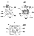
- FIG. 8 is a cross-sectional view taken along (d)-(d) in FIG. 9A is a longitudinal sectional view of the light emitting device 35A
- FIG. 9B is a sectional view taken along lines (e)-(e) in FIG. 6
- FIG. 9C is a sectional view around the transparent member A62.
- 10A is a longitudinal sectional view of the light receiving device 35B
- FIG. 10B is a sectional view of (f)-(f) in FIG. 7
- FIG. 10C is a sectional view of the periphery of the transparent member B72. It is.
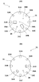
- a large number of shielding plates 24 are provided so as to surround the inside of the detection unit 23, and have a function of preventing light leakage from the outside to the inside of the detection unit 23 and light intrusion from the inside to the outside. Further, air containing smoke can enter from the outside to the inside of the detection unit 23 through a gap provided between the shielding plates 24.
- the light emitting device holder 25 ⁇ / b> A and the light emitting device holder 25 ⁇ / b> B have a cavity having a size capable of holding the light emitting device and the light receiving device therein.
- the indicator lamp holder 26 includes a cylindrical hollow space penetrating from the front surface to the back surface of the labyrinth 2, and an indicator lamp to be described later penetrates the hollow space.
- the positions of the fixing screw holes 31A to 31D in the optical device installation base 31 correspond to the positions of the notches 21A to D in the labyrinth 2, and the cover on the optical device installation base 31
- the positions of the mounting screw holes 32A to 32D correspond to the positions of the cover mounting screw holes 22A to 22D in the labyrinth 2.
- a light emitting device 35A, a light receiving device 35B, and an indicator lamp 36 protrude from the surface side of the optical device installation base 3.
- the first positioning portions 38A and 38B are provided on the surface side of the optical device mounting base 31.
- the first positioning portion 38A and the second positioning portion 38B are respectively provided on the back surface side of the labyrinth 2 shown in FIG. 2B, in other words, on the laminated surface side with the optical device installation base 31 in the labyrinth 2.
- the labyrinth is formed by fitting the pins into the holes. Misalignment between 2 and the optical member 3 is prevented.
- the first positioning portion 38A is provided at the center of the circle that forms the planar edge of the optical device installation base 31, and the second positioning portion 38B is provided on the radius of the circle that forms the planar edge of the optical device installation base 31. .
- the second positioning portion 38B exists at a position that bisects the length of a straight line connecting the center of the circle forming the planar edge of the optical device installation base 31 and the point on the edge.
- the first fixing portion 28 ⁇ / b> A is provided at the center of the circle that forms the planar edge of the labyrinth 2
- the second fixing portion 28 ⁇ / b> B is provided on the radial circumference of the circle that forms the planar edge of the labyrinth 2.
- an electronic circuit board 51, a protective plate 52 for protecting the electronic circuit board 51, and the like are provided on the back side of the optical device installation base 31.
- the area of the planar shape of the electronic circuit board 51 and the area of the planar shape of the protective plate 52 are smaller than the area of the planar shape of the optical device installation base 31 in the example in FIG. Therefore, the electronic circuit board 51 and the protective plate 52 are not observed in the plan view shown in FIG.
- a back surface opening 36A and a back surface opening 36B are provided on the back surface side of the optical device installation base 31.
- the housing 4 in the present invention Since the housing 4 in the present invention has sufficient strength, it is not damaged even by an explosion in the circuit housing portion 44. Specifically, the casing 4 in the present invention is not damaged even if a pressure of a magnitude determined by the explosion-proof regulations, for example, a pressure of about 1.5 MPa is applied by an explosion in the circuit housing portion 44. , Formed of iron plate or the like. Therefore, the flame generated by the explosion in the circuit housing portion 44 does not leak out of the photoelectric smoke detector 1 when the housing 4 is damaged.
Abstract
Description
例えば、特許文献2には、「発光素子を有し、該発光素子からの煙による散乱光もしくは透過光を受講する受光レンズを備えた警戒地区に設置される煙検出部と、・・・電気回路部とを前記煙検出部から分離して配置したことを特徴とする光電式分離型煙感知装置」が開示されている(特許文献2の実用新案登録請求の範囲)。
また、特許文献3には、「発光体および直接光、散乱光受光体を回路部の金属ケース内に納め、これらと煙感知器暗箱間を光学繊維により結合し、暗箱側光学繊維端にレンズを備え、発光、受光の作用をもたせて煙粒子を検知する構成となっている」と記載されている(特許文献3、第(2)頁、右上欄の下から1行目~左下欄の第5行)。
さらに、特許文献4には、「煙を導入するラビリンス基台と、発光素子、受光素子、電子部品等の電子回路とを分離して、両者を光ファイバーで連結したから、高温に影響を受けないラビリンス器台のみを高温室に設置して光電式煙感知装置を構成することができ、高温雰囲気下でも支障なく煙を感知できる煙感知装置」が開示されている(特許文献4、第(3)頁の第17行~第(4)頁の第3行)。
For example,
Furthermore,
また、光ファイバーを用いた光電式煙感知器では、防爆容器内部に爆発性ガスが侵入することを防ぐために、防爆容器における光ファイバーの取付部を樹脂等で充填する必要がある。よって、充填された樹脂が劣化するに伴い、防爆容器の密閉性が低下し、爆発の危険を引き起こすことがあるという問題がある。 As described in
In addition, in the photoelectric smoke detector using an optical fiber, it is necessary to fill the mounting portion of the optical fiber in the explosion-proof container with a resin or the like in order to prevent the explosive gas from entering the explosion-proof container. Therefore, as the filled resin is deteriorated, there is a problem that the sealing property of the explosion-proof container is lowered and there is a risk of explosion.
(1)電子回路基板を収容可能な回路収容部を有する防爆構造型の筐体の外側に設けられ、防爆指定区域に露出可能に形成されてなる発光装置と受光装置とを有し、前記発光装置は、筒状の内壁面A及び前記内壁面Aに囲繞された内部空間Aが前記回路収容部に通じる開口部Aを有する筒体Aと、前記内部空間Aの前記開口部Aに向かう底面に配置された発光素子と、発光素子によって発せられた光を通す透明部材Aとを有し、前記受光装置は、筒状の内壁面Bと前記内壁面Bに囲繞された内部空間Bが前記回路収容部に通じる開口部Bとを有する筒体Bと、前記内部空間Bの前記開口部Bに向かう底面に配置された受光素子と、受光素子に光を導く透明部材Bとを有し、前記内壁面Aと前記透明部材Aとの間隙、及び前記内壁面Bと前記透明部材Bとの間隙が、防爆規定に適合した幅を有し、前記開口部Aから前記透明部材Aの先端面までの透明部材Aの軸線方向における長さ、及び前記開口部Bから前記透明部材Bの先端面までの透明部材Bの軸線方向における長さが、防爆構造に適合した長さであることを特徴とする光電式煙感知器であり、
(2)前記筐体と、前記発光装置及び前記受光装置が外表面に突出して設けられてなる光学装置設置台と、前記発光装置及び前記受光装置を保持する発光装置ホルダー及び受光装置ホルダーを備えるとともに、前記光学装置設置台との積層面とは反対側の面において、気体を通過可能にする一方で外部から内部への光の侵入を防ぐ遮蔽板を備えた着脱可能なラビリンスと、が積層されてなることを特徴とする前記(1)に記載の光電式煙感知器であり、
(3)前記光学装置設置台及びラビリンスは、積層面の形状が円形であり、前記ラビリンスは、前記光学装置設置台との積層面において、縁辺の円の中心部に設けられた第1固定部と、縁辺の円の半径周上に設けられた第2固定部とを備え、前記光学装置設置台は、前記ラビリンスとの積層面において、縁辺の円の中心部に第1位置決め部と、縁辺の円の半径周上に第2位置決め部とを備え、前記第1固定部と前記第1位置決め部材とが係合し、前記第2固定部と前記第2位置決め部材とが係合してなることを特徴とする前記(2)に記載の光電式煙感知器であり、
(4)前記内壁面Aと前記透明部材Aとの間隙、及び前記内壁面Bと前記透明部材Bとの間隙の幅が、0.1mm以下であって、前記開口部Aから前記透明部材Aの先端面までの透明部材Aの軸線方向における長さ、及び前記開口部Bから前記透明部材Bの先端面までの透明部材Bの軸線方向における長さが、9.5mm以上であることを特徴とする前記(1)から(3)までのいずれか一つに記載の光電式煙感知器である。 Means for solving the problems are as follows:
(1) A light emitting device and a light receiving device which are provided outside an explosion-proof housing having a circuit housing portion capable of housing an electronic circuit board and are formed so as to be exposed to an explosion-proof designated area. The apparatus includes a cylindrical inner wall surface A and a cylindrical body A having an opening A in which the inner space A surrounded by the inner wall surface A communicates with the circuit housing portion, and a bottom surface of the inner space A facing the opening A. The light receiving device includes a cylindrical inner wall surface B and an inner space B surrounded by the inner wall surface B, and the transparent member A that transmits light emitted by the light emitting device. A cylindrical body B having an opening B communicating with the circuit housing portion, a light receiving element disposed on a bottom surface of the internal space B facing the opening B, and a transparent member B for guiding light to the light receiving element, The gap between the inner wall surface A and the transparent member A, and the inner wall surface B and the transparent member The gap with the member B has a width conforming to the explosion-proof regulations, the length in the axial direction of the transparent member A from the opening A to the front end surface of the transparent member A, and the transparent member A from the opening B The photoelectric smoke detector, characterized in that the length in the axial direction of the transparent member B to the tip surface of B is a length suitable for the explosion-proof structure,
(2) The housing, the optical device mounting base in which the light emitting device and the light receiving device are provided so as to protrude from the outer surface, and the light emitting device holder and the light receiving device holder for holding the light emitting device and the light receiving device. And a detachable labyrinth having a shielding plate that allows gas to pass through while preventing light from entering from the outside to the inside on a surface opposite to the surface on which the optical device is mounted. The photoelectric smoke detector according to (1), characterized in that:
(3) The optical device installation base and the labyrinth have a laminated surface having a circular shape, and the labyrinth is a first fixing portion provided at the center of the edge circle on the laminated surface with the optical device installation base. And a second fixing portion provided on a radius circumference of the circle of the edge, and the optical device installation table includes a first positioning portion at the center of the circle of the edge and the edge on the laminating surface with the labyrinth And a second positioning portion on a radial circumference of the circle, wherein the first fixing portion and the first positioning member are engaged, and the second fixing portion and the second positioning member are engaged. The photoelectric smoke detector according to (2), characterized in that:
(4) The width of the gap between the inner wall surface A and the transparent member A and the width of the gap between the inner wall surface B and the transparent member B are 0.1 mm or less, and the transparent member A from the opening A The length in the axial direction of the transparent member A to the distal end surface of the transparent member B and the length in the axial direction of the transparent member B from the opening B to the distal end surface of the transparent member B are 9.5 mm or more. The photoelectric smoke detector according to any one of (1) to (3).
また、本発明によると、発光装置及び受光装置の外周面における間隙を樹脂等で充填しなくても防爆性を有するので、光電式煙感知器の製造、メンテナンス等が容易であるとともに、樹脂の経年劣化によって防爆性が失われることを防ぐことができる。 According to the present invention, in the light emitting device and the light receiving device, the width of the gap and the length in the axial direction of the transparent member from the opening to the distal end surface of the transparent member are sizes suitable for the explosion-proof structure. Even if an explosion occurs in the electronic circuit board, the flame generated by the explosion disappears while passing through the gap in the light emitting device or the light receiving device, and the explosion inside the housing does not leak outside.
Further, according to the present invention, since the explosion-proof property is obtained without filling the gaps on the outer peripheral surfaces of the light emitting device and the light receiving device with resin or the like, it is easy to manufacture and maintain the photoelectric smoke detector, and It is possible to prevent loss of explosion-proof properties due to aging.
発光装置ホルダー25A及び発光装置ホルダー25Bは、内部に発光装置及び受光装置を保持することのできる大きさの空洞を有する。表示灯ホルダー26は、ラビリンス2の表面から裏面へと貫通する円筒状の中空空間を備え、この中空空間を後述する表示灯が貫通する。 As shown in FIG. 2 (A), the
The light emitting device holder 25 </ b> A and the light emitting device holder 25 </ b> B have a cavity having a size capable of holding the light emitting device and the light receiving device therein. The
また、光学装置設置台3の表面側には、発光装置35A、受光装置35B、及び表示灯36が突出してなる。発光装置35Aと受光装置35Bとは、光軸が120°程度の角度で交差するように配置され、発光装置35Aから発せられた光が、煙によって散乱し、受光装置35Bに到達することによって煙の存在が感知される。
表示灯36は、使用者に視認可能な光信号を発することのできる装置であればよく、通常、筒状体である。 As shown in FIG. 1, an optical
A
The
また、図3(B)で示されるように、光学装置設置台31の裏面側には、裏面開口36Aと裏面開口36Bとが設けられる。裏面開口36Aは、後述するように発光装置35Aから電子回路基板51へと到る配線部材59Bを内側に通し、裏面開口36Bは、受光装置35Bから電子回路基板51へと到る配線部材59Cを内側に通す。なお、図3(B)には図示されていないが、光学装置設置台31の裏面には、後述する回路取付ねじ57が挿通されるねじ穴が設けられていてもよい。 On the back side of the optical
Further, as shown in FIG. 3B, a
また、台座部42及び容器部45の外側面には、回路収容部44と外部空間とを連通する側口が設けられていてもよく、図4における例では、3つの側口44A、44B、及び44Dが設けられる。 As shown in FIG. 1A and FIG. 4, the
Moreover, the side surface which connects the
また、図5には図示されていないが、カバー5が取り付けられた後で、カバー5を貫通するカバー取付ねじが、カバー取付ねじ穴22A~D及び32A~Dに取り付けられることにより、カバー5が固定される。 In FIG. 5, the fixing screws 51A to 51D pass through the
Although not shown in FIG. 5, after the
なお、図5には図示されていないが、検知部23の外側には、外部からの虫等の異物の侵入を防ぐために、防虫網が設けられていてもよい。 When the
Although not shown in FIG. 5, an insect net may be provided outside the
なお、筐体4、光学装置設置台31、及び栓体54A、B、Dを、別の部材とせずに一体として設計してもよい。 When the
Note that the
表示灯36の外周部も防爆構造型であればよく、具体的には、回路収容部44において発生した火炎が表示灯36の外周面近傍から光電式煙感知器1の外部へと漏れ出さないように設計されていればよい。例えば、表示灯36の外周面と表示灯ホルダー26の内壁面との間を樹脂等で隙間なく充填すればよい。また、表示灯36の外周面と表示灯ホルダー26のない壁面との間には、防爆規定に適合する程度の寸法の間隙が設けられていてもよい。例えば、幅が0.1mm以下であって、表示灯36の軸線方向における長さが9.5mm以上である間隙が設けられていてもよい。 As shown in FIG. 8, the
The outer peripheral portion of the
透明部材A62の一方の端面には発光素子61が設けられ、他方の端面、言い換えると、透明部材Aの先端面69は、光を外部へ放射する機能を有する。また、図6(B)に示すように、透明部材Aの先端面69近傍には、光の放射方向をさらに限定するために、透明部材A62の端面積よりも小さい穴を有するスリット板52Aが設けられていてもよい。 As shown in FIG. 9A, the
The
間隙の幅は、図9(C)に示されるように、透明部材A62の軸線方向と垂直な方向における断面図において、内壁面A64上のある一点から透明部材A62の外周面までの距離として求められる。 An internal space A66 surrounded by a cylindrical inner wall surface A64 is provided in the cylindrical body A63 so as to hold the transparent member A62. In the example shown in FIG. 6C, the internal space A66 is provided as a cylindrical shape whose cross-sectional area is larger than the cross-sectional area of the transparent member A62. Therefore, a gap having a width of W1 is generated between the inner wall surface A64 and the transparent member A62.
As shown in FIG. 9C, the width of the gap is obtained as a distance from a certain point on the inner wall surface A64 to the outer peripheral surface of the transparent member A62 in a cross-sectional view in the direction perpendicular to the axial direction of the transparent member A62. It is done.
なお、透明部材の中心軸線と内部空間の中心軸線とが一致しない例のように、透明部材の位置によって間隙の幅が異なる例、言い換えると間隙の幅W1及びW2が一様ではない例においては、間隙の幅が最も大きくなる位置における幅の長さが0.1mm以下であればよい。さらに具体的には、透明部材の軸線方向、及び周方向における全ての点のうち、内壁面までの距離が最大となる点における間隙が、0.1mm以下であればよい。 The widths W1 and W2 of the gap and the distances L1 and L2 may be of a size that meets the explosion-proof regulations. If these sizes comply with the explosion-proof regulations, the flame generated by the explosion in the
In an example in which the width of the gap differs depending on the position of the transparent member, in other words, in an example in which the widths W1 and W2 of the gap are not uniform, as in the example in which the central axis of the transparent member does not match the central axis of the internal space. The length of the width at the position where the width of the gap is the largest may be 0.1 mm or less. More specifically, the gap at the point where the distance to the inner wall surface becomes the maximum among all the points in the axial direction and the circumferential direction of the transparent member may be 0.1 mm or less.
まず、筐体4の側口44A、44B、及び44Dに防爆性のケーブルグランドを取り付け、筐体4とセンサー部3とラビリンス2とを積層し、固定ねじ51A~51Dを締めこむ。さらに、カバー5を取り付け、カバー取付ねじを締めこむことによって、光電式煙感知器1が得られる。光電式煙感知器1は、筐体4の底面を地上に置くようにして設置してもよいし、筐体4の底面を施設の壁面や天井面に取り付けるようにして設置してもよい。 Consider an example in which the
First, an explosion-proof cable gland is attached to the
発光装置35A及び受光装置35Bは、光学装置設置台31の上面に突出して設けられており、図5で示されるように、光電式煙感知器1においてはラビリンス2の検知部23に位置する。よって、発光装置35A及び受光装置35Bは、空気穴7から侵入する爆発性のガスに晒されており、言い換えると、防爆指定区域に露出されている。
光電式煙感知器1の内部に侵入した空気が煙を含んでいると、発光装置35Aから発せられた光が散乱されることにより、受光装置35Bに到る光のパターンが変化する。このような受光パターンの変化は、配線部材59Cを介して電子回路基板51へ電気信号として伝えられる。受光パターンの変化についての電気信号を受け取った電子回路基板51は、煙が発生したことを外部へと知らせることができるように、電気信号を出力する。例えば、配線部材59Dを介して電気信号を出力することによって、表示灯36から発せられる光の色等が変化するように設計すればよい。このような態様では、観察者が表示灯36から発せられる光の変化を観察することによって、煙が発生したか否かを確認することができる。 As shown in FIG. 1B, the
The light emitting device 35 </ b> A and the light receiving device 35 </ b> B are provided so as to protrude from the upper surface of the optical
If the air that has entered the inside of the
開口部A68へと到った火炎は、内壁面A64と透明部材A62との間に生じる間隙から透明部材Aの先端部69へと向かって進む。しかし、間隙の幅W1及び長さL1は防爆規定に適合した寸法である。よって、火炎は内部空間66を進行している間に立ち消え、透明部材Aの先端面69を超えることがない。以上より、空気穴7を介してラビリンス2の検知部23に侵入した空気に含有される爆発性のガスに、回路収容部44から上昇してきた火炎が引火し、ラビリンス2の検知部23において爆発が発生し、ひいては光電式煙感知器1を設置した設備全体が爆発するという大事故が引き起こされるのを防止することができる。また、受光装置35Bにおいても、発光装置35Aと同様に間隙が設けられているので、回路収容部44から上昇してきた火炎が図10に示される透明部材Bの先端面79を超えることがない。
より具体的には、通常の状態において爆発性雰囲気をしばしば生成する可能性のある第一類危険箇所に光電式煙感知器1が設置されることにより、光電式煙感知器1における発光装置35Aと受光装置35Bとが第一類危険箇所に露出されても、回路収容部44において発生した火炎が外部のガスに引火することがない。 Further, the flame generated by the explosion in the
The flame that has reached the opening A68 advances from the gap formed between the inner wall surface A64 and the transparent member A62 toward the
More specifically, the
2 ラビリンス
3 センサー部
4 筐体部
5 カバー
7 空気穴
21A~21D 切欠部
31A~31D 41A~D 固定ねじ穴
22A~22D 32A~32D カバー取付用ねじ穴
23 検知部
24 遮蔽板
25A 発光装置ホルダー
25B 受光装置ホルダー
26 表示灯ホルダー
26A、27A、27B、36A、36B 裏面開口
28A 第1固定部
28B 第2固定部
31 光学装置設置台
35A 発光装置
35B 受光装置
36 表示灯
38A 第1位置決め部
38B 第2位置決め部
42 台座部
43 シール部
44 回路収容部
44A、44B,44D 側口
45 容器部
51 電子回路基板
51A~D 固定ねじ
52 保護プレート
52A スリット板
52B 保護カバー
53 検出領域
54A、54B、54D 栓体
54、55、56 シール面
57 回路取付ねじ
58B、58C 中空部
59B、59C、59D 配線部材
61 発光素子
62 透明部材A
63 筒体A
64 内壁面A
66 内部空間A
67、77 透明部材固定部
68 開口部A
69 透明部材Aの先端面
71 受光素子
72 透明部材B
73 筒体B
74 内壁面B
76 内部空間B
78 開口部B
79 透明部材Bの先端面 DESCRIPTION OF
38A
53
63 Tube A
64 Inner wall surface A
66 Internal space A
67, 77 Transparent
69
73 Cylinder B
74 Inner wall surface B
76 Internal space B
78 Opening B
79 Tip surface of transparent member B
Claims (4)
- 電子回路基板を収容可能な回路収容部を有する防爆構造型の筐体の外側に設けられ、防爆指定区域に露出可能に形成されてなる発光装置と受光装置とを有し、
前記発光装置は、筒状の内壁面A及び前記内壁面Aに囲繞された内部空間Aが前記回路収容部に通じる開口部Aを有する筒体Aと、前記内部空間Aの前記開口部Aに向かう底面に配置された発光素子と、発光素子によって発せられた光を通す透明部材Aとを有し、
前記受光装置は、筒状の内壁面Bと前記内壁面Bに囲繞された内部空間Bが前記回路収容部に通じる開口部Bとを有する筒体Bと、前記内部空間Bの前記開口部Bに向かう底面に配置された受光素子と、受光素子に光を導く透明部材Bとを有し、
前記内壁面Aと前記透明部材Aとの間隙、及び前記内壁面Bと前記透明部材Bとの間隙が、防爆規定に適合した幅を有し、
前記開口部Aから前記透明部材Aの先端面までの透明部材Aの軸線方向における長さ、及び前記開口部Bから前記透明部材Bの先端面までの透明部材Bの軸線方向における長さが、防爆構造に適合した長さであることを特徴とする光電式煙感知器。 A light-emitting device and a light-receiving device that are provided outside an explosion-proof housing having a circuit housing portion capable of housing an electronic circuit board, and are formed so as to be exposed to an explosion-proof designated area;
In the light emitting device, a cylindrical inner wall surface A and an inner space A surrounded by the inner wall surface A have a cylindrical body A having an opening A that leads to the circuit housing portion, and the opening A of the inner space A. A light emitting element disposed on the bottom surface facing, and a transparent member A that transmits light emitted by the light emitting element;
The light receiving device includes a cylindrical body B having a cylindrical inner wall surface B and an opening B through which the inner space B surrounded by the inner wall B communicates with the circuit housing portion, and the opening B of the inner space B. A light receiving element disposed on the bottom surface facing the light source, and a transparent member B for guiding light to the light receiving element,
The gap between the inner wall surface A and the transparent member A and the gap between the inner wall surface B and the transparent member B have a width that conforms to the explosion-proof regulations,
The length in the axial direction of the transparent member A from the opening A to the distal end surface of the transparent member A, and the length in the axial direction of the transparent member B from the opening B to the distal end surface of the transparent member B, A photoelectric smoke detector characterized in that it has a length suitable for an explosion-proof structure. - 前記筐体と、
前記発光装置及び前記受光装置が外表面に突出して設けられてなる光学装置設置台と、
前記発光装置及び前記受光装置を保持する発光装置ホルダー及び受光装置ホルダーを備えるとともに、前記光学装置設置台との積層面とは反対側の面において、気体を通過可能にする一方で外部から内部への光の侵入を防ぐ遮蔽板を備えた着脱可能なラビリンスと、
が積層されてなることを特徴とする請求項1に記載の光電式煙感知器。 The housing;
An optical device mounting base in which the light emitting device and the light receiving device are provided to protrude on the outer surface;
A light-emitting device holder and a light-receiving device holder for holding the light-emitting device and the light-receiving device are provided, and gas is allowed to pass through from the outside to the inside on the surface opposite to the laminated surface with the optical device installation base. Removable labyrinth with a shielding plate that prevents the intrusion of light,
The photoelectric smoke sensor according to claim 1, wherein the photoelectric smoke detectors are stacked. - 前記光学装置設置台及びラビリンスは、積層面の形状が円形であり、
前記ラビリンスは、前記光学装置設置台との積層面において、縁辺の円の中心部に設けられた第1固定部と、縁辺の円の半径周上に設けられた第2固定部とを備え、
前記光学装置設置台は、前記ラビリンスとの積層面において、縁辺の円の中心部に第1位置決め部と、縁辺の円の半径周上に第2位置決め部とを備え、
前記第1固定部と前記第1位置決め部材とが係合し、前記第2固定部と前記第2位置決め部材とが係合してなることを特徴とする請求項2に記載の光電式煙感知器。 The optical device installation table and the labyrinth have a circular laminated surface shape,
The labyrinth includes a first fixing portion provided at a central portion of a circle of an edge and a second fixing portion provided on a radial circumference of the circle of the edge, on a laminated surface with the optical device installation base,
The optical device installation table includes a first positioning portion at the center of an edge circle and a second positioning portion on a radial circumference of the edge circle on the laminating surface with the labyrinth,
The photoelectric smoke sensing device according to claim 2, wherein the first fixing portion and the first positioning member are engaged, and the second fixing portion and the second positioning member are engaged. vessel. - 前記内壁面Aと前記透明部材Aとの間隙、及び前記内壁面Bと前記透明部材Bとの間隙の幅が、0.1mm以下であって、
前記開口部Aから前記透明部材Aの先端面までの透明部材Aの軸線方向における長さ、及び前記開口部Bから前記透明部材Bの先端面までの透明部材Bの軸線方向における長さが、9.5mm以上であることを特徴とする請求項1から3までのいずれか一項に記載の光電式煙感知器。 The gap between the inner wall surface A and the transparent member A, and the width of the gap between the inner wall surface B and the transparent member B is 0.1 mm or less,
The length in the axial direction of the transparent member A from the opening A to the distal end surface of the transparent member A, and the length in the axial direction of the transparent member B from the opening B to the distal end surface of the transparent member B, The photoelectric smoke detector according to any one of claims 1 to 3, wherein the photoelectric smoke detector is 9.5 mm or more.
Priority Applications (7)
| Application Number | Priority Date | Filing Date | Title |
|---|---|---|---|
| CN201480071539.4A CN106663356B (en) | 2014-07-14 | 2014-07-14 | Photoelectric smoke sensor |
| KR1020167017712A KR101874970B1 (en) | 2014-07-14 | 2014-07-14 | Photoelectric smoke sensor |
| PCT/JP2014/003717 WO2016009460A1 (en) | 2014-07-14 | 2014-07-14 | Photoelectric smoke sensor |
| JP2014560966A JP5771760B1 (en) | 2014-07-14 | 2014-07-14 | Photoelectric smoke detector |
| RU2016126414A RU2646195C1 (en) | 2014-07-14 | 2014-07-14 | Photoelectric smoke detector |
| EP14897830.7A EP3171347B1 (en) | 2014-07-14 | 2014-07-14 | Photoelectric smoke sensor |
| US15/190,498 US10054542B2 (en) | 2014-07-14 | 2016-06-23 | Photoelectric smoke detector |
Applications Claiming Priority (1)
| Application Number | Priority Date | Filing Date | Title |
|---|---|---|---|
| PCT/JP2014/003717 WO2016009460A1 (en) | 2014-07-14 | 2014-07-14 | Photoelectric smoke sensor |
Related Child Applications (1)
| Application Number | Title | Priority Date | Filing Date |
|---|---|---|---|
| US15/190,498 Continuation-In-Part US10054542B2 (en) | 2014-07-14 | 2016-06-23 | Photoelectric smoke detector |
Publications (1)
| Publication Number | Publication Date |
|---|---|
| WO2016009460A1 true WO2016009460A1 (en) | 2016-01-21 |
Family
ID=54188029
Family Applications (1)
| Application Number | Title | Priority Date | Filing Date |
|---|---|---|---|
| PCT/JP2014/003717 WO2016009460A1 (en) | 2014-07-14 | 2014-07-14 | Photoelectric smoke sensor |
Country Status (7)
| Country | Link |
|---|---|
| US (1) | US10054542B2 (en) |
| EP (1) | EP3171347B1 (en) |
| JP (1) | JP5771760B1 (en) |
| KR (1) | KR101874970B1 (en) |
| CN (1) | CN106663356B (en) |
| RU (1) | RU2646195C1 (en) |
| WO (1) | WO2016009460A1 (en) |
Cited By (4)
| Publication number | Priority date | Publication date | Assignee | Title |
|---|---|---|---|---|
| KR20170090366A (en) * | 2016-01-28 | 2017-08-07 | 닛폰 도라이 케미카루 가부시키가이샤 | Photoelectric smoke detector |
| US10151693B2 (en) | 2015-08-25 | 2018-12-11 | Fenwal Controls Of Japan, Ltd. | Photoelectric smoke sensor |
| WO2020003712A1 (en) | 2018-06-25 | 2020-01-02 | ホーチキ株式会社 | Fire detection device |
| TWI788369B (en) * | 2017-06-14 | 2023-01-01 | 日商報知希股份有限公司 | Alarm device |
Families Citing this family (9)
| Publication number | Priority date | Publication date | Assignee | Title |
|---|---|---|---|---|
| CN107478576B (en) * | 2016-06-07 | 2024-02-20 | 宁波方太厨具有限公司 | Protective structure of oil smoke sensor |
| KR101876898B1 (en) * | 2018-01-25 | 2018-07-10 | 주식회사 아이알티코리아 | Fire sensing device |
| CA3099040A1 (en) | 2018-05-09 | 2019-11-14 | Carrier Corporation | Smoke chamber for multiwave multiangle smoke detector |
| CN111199628A (en) | 2018-11-20 | 2020-05-26 | 海湾安全技术有限公司 | Smoke detector |
| JP6661153B1 (en) * | 2019-04-25 | 2020-03-11 | 株式会社千代田防災 | Installation equipment for smoke detectors for fire and smoke control equipment |
| CN110009865A (en) * | 2019-05-13 | 2019-07-12 | 中国船舶重工集团公司第七0三研究所 | The explosion-proof aspirating smoke detector of N-shaped |
| CN110567850A (en) * | 2019-08-26 | 2019-12-13 | 苏州双刘精密仪器有限公司 | High-sensitivity optical fiber sensing system based on big data analysis |
| EP3907714B1 (en) * | 2020-05-08 | 2024-02-21 | Carrier Corporation | Condensation prevention in an aspirating smoke detection system |
| CN117175045B (en) * | 2023-11-02 | 2024-03-22 | 安徽中科中涣智能装备股份有限公司 | Battery box thermal runaway detection device based on spectrum |
Citations (2)
| Publication number | Priority date | Publication date | Assignee | Title |
|---|---|---|---|---|
| JPH11175860A (en) * | 1997-12-16 | 1999-07-02 | Nohmi Bosai Ltd | Heat sensor for explosion prevention |
| JP2002358583A (en) * | 2001-05-31 | 2002-12-13 | Nittan Co Ltd | Fire detector |
Family Cites Families (39)
| Publication number | Priority date | Publication date | Assignee | Title |
|---|---|---|---|---|
| US3555532A (en) * | 1968-10-29 | 1971-01-12 | Graham Stuart Corp | Vapor or particle detection device |
| CH508251A (en) * | 1970-07-23 | 1971-05-31 | Cerberus Ag | Ionization fire alarms |
| US4396840A (en) * | 1980-10-01 | 1983-08-02 | Matsushita Electric Works, Ltd. | Ionization type smoke sensing device |
| JPS58129145A (en) | 1982-01-28 | 1983-08-02 | Mitsubishi Electric Corp | Controller for hot water reserving type electric water heater |
| JPS58129145U (en) | 1982-02-25 | 1983-09-01 | ホーチキ株式会社 | Photoelectric separate smoke detector |
| US4539556A (en) * | 1983-04-15 | 1985-09-03 | Pittway Corporation | Combustion products detector with accelerated test |
| CA1267735A (en) * | 1986-01-17 | 1990-04-10 | Nohmi Bosai Kogyo Co., Ltd. | Ionization type-smoke detector |
| JPS638538A (en) | 1986-06-27 | 1988-01-14 | Matsushita Electric Ind Co Ltd | Smoke sensor |
| JPS6320050A (en) | 1986-07-10 | 1988-01-27 | Kotobuki Giken Kogyo Kk | Screw decanter type centrifgal concentrator |
| JPS63163698A (en) * | 1986-12-26 | 1988-07-07 | ホーチキ株式会社 | Scattered light type smoke sensor |
| JPS63239592A (en) * | 1987-03-27 | 1988-10-05 | ホーチキ株式会社 | Photoelectric type smoke sensor |
| US5021677A (en) * | 1989-05-02 | 1991-06-04 | Nohmi Bosai Kabushiki Kaisha | Light-scattering-type smoke detector |
| FR2666163B1 (en) * | 1990-08-22 | 1995-03-17 | Bertin & Cie | OPTO-ELECTRONIC DEVICE FOR DETECTING SMOKE OR GAS SUSPENDED IN AIR. |
| CN1053677A (en) * | 1991-02-09 | 1991-08-07 | 北京市天坛仪器仪表公司 | Measure the combustable gas concentration compound sensor |
| CN2107741U (en) * | 1991-11-19 | 1992-06-17 | 山西耀华高技术公司 | Infrared explosion-proof camera shooting and recording device for mine use |
| DE69317147T2 (en) * | 1992-04-25 | 1998-10-01 | Nohmi Bosai Ltd | Fire alarm |
| US5400014A (en) * | 1993-07-12 | 1995-03-21 | Detection Systems, Inc. | Smoke detector with dark chamber |
| JP2787001B2 (en) * | 1994-12-12 | 1998-08-13 | ホーチキ株式会社 | Photoelectric smoke detector |
| EP0821330B1 (en) * | 1996-07-22 | 2002-09-04 | Siemens Building Technologies AG | Smoke detector |
| CA2293830C (en) * | 1999-12-31 | 2008-07-29 | Digital Security Controls Ltd. | Photoelectric smoke detector and chamber therefor |
| US6778091B2 (en) * | 2001-01-09 | 2004-08-17 | Qualey, Iii James R. | Smoke chamber |
| CN2466613Y (en) * | 2001-02-08 | 2001-12-19 | 高明 | Explosionproof pressure-resistant optoelectric liquid level sensor |
| AU762183B2 (en) * | 2001-04-24 | 2003-06-19 | Matsushita Electric Works Ltd. | Fire detector unit |
| JP3938750B2 (en) | 2003-01-27 | 2007-06-27 | ホーチキ株式会社 | smoke detector |
| RU2288505C1 (en) * | 2005-03-21 | 2006-11-27 | Закрытое акционерное общество "Светлана-Оптоэлектроника" | Smoke detector |
| RU49321U1 (en) * | 2005-03-28 | 2005-11-10 | Общество с ограниченной ответственностью "Конструкторское Бюро Пожарной Автоматики" | FIRE DETECTOR HOUSING WITH PROTECTIVE SCREEN |
| JP4866348B2 (en) * | 2005-03-31 | 2012-02-01 | 日本フェンオール株式会社 | Photoelectric smoke detector |
| EA007638B1 (en) * | 2005-04-12 | 2006-12-29 | Одо "Бмк-Систем" | Fire alarm device |
| US8610586B2 (en) * | 2008-03-24 | 2013-12-17 | Panasonic Corporation | Sensor |
| JP5153709B2 (en) * | 2009-03-31 | 2013-02-27 | 能美防災株式会社 | Photoelectric smoke detector |
| KR20100037539A (en) * | 2008-10-01 | 2010-04-09 | 노미 보사이 가부시키가이샤 | Photoelectric smoke sensor |
| CN201374114Y (en) | 2009-04-03 | 2009-12-30 | 郑州净瓶高科有限公司 | Explosion-proof fire detecting device |
| CN101750149A (en) * | 2010-01-14 | 2010-06-23 | 内蒙古科技大学 | Vacuum chamber radiation source temperature sensor |
| CN102338737A (en) * | 2010-07-21 | 2012-02-01 | 友丽系统制造股份有限公司 | Photoelectric gas sensing device and its manufacturing method |
| JP6145041B2 (en) * | 2011-06-30 | 2017-06-07 | ホーチキ株式会社 | Scattered light smoke detector |
| KR101269239B1 (en) | 2012-05-04 | 2013-05-30 | (주)우창전기산업 | Explosion prevention type smoke detector having barrier |
| DE102013213721B4 (en) * | 2013-03-07 | 2015-10-22 | Siemens Schweiz Ag | Fire alarm system for use in a nuclear or hazardous area |
| US9196141B1 (en) * | 2015-05-15 | 2015-11-24 | Google, Inc. | Smoke detector chamber |
| US9514623B1 (en) * | 2015-05-15 | 2016-12-06 | Google Inc. | Smoke detector chamber architecture and related methods using two different wavelengths of light |
-
2014
- 2014-07-14 JP JP2014560966A patent/JP5771760B1/en active Active
- 2014-07-14 WO PCT/JP2014/003717 patent/WO2016009460A1/en active Application Filing
- 2014-07-14 CN CN201480071539.4A patent/CN106663356B/en active Active
- 2014-07-14 RU RU2016126414A patent/RU2646195C1/en active
- 2014-07-14 EP EP14897830.7A patent/EP3171347B1/en active Active
- 2014-07-14 KR KR1020167017712A patent/KR101874970B1/en active IP Right Grant
-
2016
- 2016-06-23 US US15/190,498 patent/US10054542B2/en active Active
Patent Citations (2)
| Publication number | Priority date | Publication date | Assignee | Title |
|---|---|---|---|---|
| JPH11175860A (en) * | 1997-12-16 | 1999-07-02 | Nohmi Bosai Ltd | Heat sensor for explosion prevention |
| JP2002358583A (en) * | 2001-05-31 | 2002-12-13 | Nittan Co Ltd | Fire detector |
Cited By (7)
| Publication number | Priority date | Publication date | Assignee | Title |
|---|---|---|---|---|
| US10151693B2 (en) | 2015-08-25 | 2018-12-11 | Fenwal Controls Of Japan, Ltd. | Photoelectric smoke sensor |
| KR20170090366A (en) * | 2016-01-28 | 2017-08-07 | 닛폰 도라이 케미카루 가부시키가이샤 | Photoelectric smoke detector |
| JP2017138968A (en) * | 2016-01-28 | 2017-08-10 | 日本ドライケミカル株式会社 | Photoelectric smoke sensor |
| KR102554162B1 (en) * | 2016-01-28 | 2023-07-12 | 닛폰 도라이 케미카루 가부시키가이샤 | Photoelectric smoke detector |
| TWI788369B (en) * | 2017-06-14 | 2023-01-01 | 日商報知希股份有限公司 | Alarm device |
| WO2020003712A1 (en) | 2018-06-25 | 2020-01-02 | ホーチキ株式会社 | Fire detection device |
| US11614396B2 (en) | 2018-06-25 | 2023-03-28 | Hochiki Corporation | Fire detection device |
Also Published As
| Publication number | Publication date |
|---|---|
| CN106663356A (en) | 2017-05-10 |
| US10054542B2 (en) | 2018-08-21 |
| JP5771760B1 (en) | 2015-09-02 |
| EP3171347A4 (en) | 2017-11-29 |
| JPWO2016009460A1 (en) | 2017-04-27 |
| KR101874970B1 (en) | 2018-07-05 |
| US20160305874A1 (en) | 2016-10-20 |
| KR20160095036A (en) | 2016-08-10 |
| EP3171347A1 (en) | 2017-05-24 |
| CN106663356B (en) | 2019-02-22 |
| RU2646195C1 (en) | 2018-03-01 |
| EP3171347B1 (en) | 2020-06-10 |
Similar Documents
| Publication | Publication Date | Title |
|---|---|---|
| JP5771760B1 (en) | Photoelectric smoke detector | |
| US10151693B2 (en) | Photoelectric smoke sensor | |
| CN101894442B (en) | Fire alarm | |
| CN108291824B (en) | Explosion-proof housing for a device for transmitting and receiving electromagnetic radiation | |
| US9170341B2 (en) | Flame-proof radiation detector with wireless communication means | |
| US8528401B2 (en) | Explosion-proof device | |
| US10775035B2 (en) | Explosion-proof enclosure with flame path maintenance and protection means | |
| CA3027361A1 (en) | Explosion-proof enclosures including light transmissive portions | |
| JP2019174463A5 (en) | ||
| KR102554162B1 (en) | Photoelectric smoke detector | |
| CN107016815A (en) | Photoelectric smoke sensor | |
| JP6912358B2 (en) | Gas detector | |
| KR101229047B1 (en) | gas sensor having a explosion and flame proof | |
| WO2021107004A1 (en) | Oil mist detection device | |
| JP2001041844A (en) | Liquid leakage sensor |
Legal Events
| Date | Code | Title | Description |
|---|---|---|---|
| ENP | Entry into the national phase |
Ref document number: 2014560966 Country of ref document: JP Kind code of ref document: A |
|
| 121 | Ep: the epo has been informed by wipo that ep was designated in this application |
Ref document number: 14897830 Country of ref document: EP Kind code of ref document: A1 |
|
| ENP | Entry into the national phase |
Ref document number: 20167017712 Country of ref document: KR Kind code of ref document: A |
|
| REEP | Request for entry into the european phase |
Ref document number: 2014897830 Country of ref document: EP |
|
| WWE | Wipo information: entry into national phase |
Ref document number: 2014897830 Country of ref document: EP |
|
| NENP | Non-entry into the national phase |
Ref country code: DE |
|
| ENP | Entry into the national phase |
Ref document number: 2016126414 Country of ref document: RU Kind code of ref document: A |